CN111237193A - Discharge pipe assemblies, housing assemblies, compressors and refrigeration units for compressors - Google Patents
Discharge pipe assemblies, housing assemblies, compressors and refrigeration units for compressorsDownload PDFInfo
- Publication number
- CN111237193A CN111237193ACN202010078991.0ACN202010078991ACN111237193ACN 111237193 ACN111237193 ACN 111237193ACN 202010078991 ACN202010078991 ACN 202010078991ACN 111237193 ACN111237193 ACN 111237193A
- Authority
- CN
- China
- Prior art keywords
- compressor
- valve
- section
- assembly
- pipe
- Prior art date
- Legal status (The legal status is an assumption and is not a legal conclusion. Google has not performed a legal analysis and makes no representation as to the accuracy of the status listed.)
- Pending
Links
- 238000005057refrigerationMethods0.000titleclaimsdescription16
- 230000000712assemblyEffects0.000title2
- 238000000429assemblyMethods0.000title2
- 238000000034methodMethods0.000claimsdescription13
- 230000008569processEffects0.000claimsdescription12
- 230000002093peripheral effectEffects0.000claimsdescription5
- 239000003507refrigerantSubstances0.000abstractdescription16
- 230000002159abnormal effectEffects0.000abstractdescription14
- 238000005299abrasionMethods0.000abstract1
- 238000009434installationMethods0.000description23
- 230000008021depositionEffects0.000description10
- 230000009286beneficial effectEffects0.000description8
- 238000004891communicationMethods0.000description5
- 230000000694effectsEffects0.000description5
- 238000010586diagramMethods0.000description4
- 239000003921oilSubstances0.000description4
- 238000007789sealingMethods0.000description4
- 239000010687lubricating oilSubstances0.000description3
- 238000004519manufacturing processMethods0.000description2
- 239000000463materialSubstances0.000description2
- 230000004075alterationEffects0.000description1
- 230000006835compressionEffects0.000description1
- 238000007906compressionMethods0.000description1
- 230000007423decreaseEffects0.000description1
- 230000005484gravityEffects0.000description1
- 238000005461lubricationMethods0.000description1
- 230000007246mechanismEffects0.000description1
- 238000012986modificationMethods0.000description1
- 230000004048modificationEffects0.000description1
- 230000000149penetrating effectEffects0.000description1
- 238000005096rolling processMethods0.000description1
- 238000006467substitution reactionMethods0.000description1
Images


Classifications
- F—MECHANICAL ENGINEERING; LIGHTING; HEATING; WEAPONS; BLASTING
- F04—POSITIVE - DISPLACEMENT MACHINES FOR LIQUIDS; PUMPS FOR LIQUIDS OR ELASTIC FLUIDS
- F04C—ROTARY-PISTON, OR OSCILLATING-PISTON, POSITIVE-DISPLACEMENT MACHINES FOR LIQUIDS; ROTARY-PISTON, OR OSCILLATING-PISTON, POSITIVE-DISPLACEMENT PUMPS
- F04C29/00—Component parts, details or accessories of pumps or pumping installations, not provided for in groups F04C18/00 - F04C28/00
- F04C29/12—Arrangements for admission or discharge of the working fluid, e.g. constructional features of the inlet or outlet
- F04C29/124—Arrangements for admission or discharge of the working fluid, e.g. constructional features of the inlet or outlet with inlet and outlet valves specially adapted for rotary or oscillating piston pumps
- F04C29/126—Arrangements for admission or discharge of the working fluid, e.g. constructional features of the inlet or outlet with inlet and outlet valves specially adapted for rotary or oscillating piston pumps of the non-return type
- F—MECHANICAL ENGINEERING; LIGHTING; HEATING; WEAPONS; BLASTING
- F04—POSITIVE - DISPLACEMENT MACHINES FOR LIQUIDS; PUMPS FOR LIQUIDS OR ELASTIC FLUIDS
- F04C—ROTARY-PISTON, OR OSCILLATING-PISTON, POSITIVE-DISPLACEMENT MACHINES FOR LIQUIDS; ROTARY-PISTON, OR OSCILLATING-PISTON, POSITIVE-DISPLACEMENT PUMPS
- F04C29/00—Component parts, details or accessories of pumps or pumping installations, not provided for in groups F04C18/00 - F04C28/00
- F04C29/0021—Systems for the equilibration of forces acting on the pump
- F04C29/0035—Equalization of pressure pulses
Landscapes
- Engineering & Computer Science (AREA)
- Mechanical Engineering (AREA)
- General Engineering & Computer Science (AREA)
- Compressor (AREA)
Abstract
Description
Translated fromChinese技术领域technical field
本发明涉及压缩机技术领域,尤其是涉及一种用于压缩机的排气管组件、壳体组件、压缩机和制冷装置。The present invention relates to the technical field of compressors, and in particular, to an exhaust pipe assembly, a casing assembly, a compressor and a refrigeration device for a compressor.
背景技术Background technique
在目前普遍使用的制冷装置中,压缩机从上一回运行后停机到可以再次启动时,压缩机的吸气侧与排气侧的压力差必须要达到某个要求的范围内才可以重新启动,特别是对于滚动转子式压缩机来说,该压力差必须达到一个较小的数值例如1kgf/cm2以内,否则将无法启动再次启动压缩机,从而无法实现快速启动功能。In the currently commonly used refrigeration device, when the compressor is stopped after the last operation and can be restarted, the pressure difference between the suction side and the exhaust side of the compressor must reach a certain required range before restarting. , especially for rolling rotor compressors, the pressure difference must reach a small value such as within 1kgf/cm2, otherwise it will not be able to start the compressor again, so that the fast start function cannot be achieved.
同时,压缩机停机后,在部分条件下,系统中的冷媒会通过排气管进入压缩机内部,使压缩机内冷媒发生沉积,从而使压缩机底部油池溶解过多冷媒导致润滑油粘度下降,当压缩机再次启动时,压缩机内部的润滑油粘度下降可能导致异常磨损,降低了压缩机的可靠性。At the same time, after the compressor is stopped, under some conditions, the refrigerant in the system will enter the compressor through the exhaust pipe, causing the refrigerant in the compressor to deposit, so that the oil pool at the bottom of the compressor dissolves too much refrigerant and causes the viscosity of the lubricating oil to drop. , When the compressor starts again, the viscosity of the lubricating oil inside the compressor decreases, which may cause abnormal wear and reduce the reliability of the compressor.
发明内容SUMMARY OF THE INVENTION
本发明旨在至少解决现有技术中存在的技术问题之一。为此,本发明的一个目的在于提出一种用于压缩机的排气管组件,所述排气管组件有利于实现压缩机的快速启动且可以提高压缩机的可靠性。The present invention aims to solve at least one of the technical problems existing in the prior art. To this end, an object of the present invention is to provide an exhaust pipe assembly for a compressor, which is beneficial to realize the quick start of the compressor and can improve the reliability of the compressor.
本发明还提出一种具有上述用于压缩机的排气管组件的壳体组件。The present invention also provides a housing assembly having the above-mentioned exhaust pipe assembly for a compressor.
本发明还提出一种具有上述用于压缩机的壳体组件的压缩机。The present invention also proposes a compressor having the above-mentioned casing assembly for a compressor.
本发明还提出一种具有上述压缩机的制冷装置。The present invention also provides a refrigeration device with the above-mentioned compressor.
根据本发明第一方面实施例的用于压缩机的排气管组件,包括:排气管,所述排气管内限定出排气通道,所述排气通道具有进气口和出气口;和单向阀,所述单向阀设在所述排气通道内,所述单向阀在从所述进气口到所述出气口的方向上单向导通。An exhaust pipe assembly for a compressor according to an embodiment of the first aspect of the present invention includes: an exhaust pipe defining an exhaust passage therein, the exhaust passage having an air inlet and an air outlet; and A one-way valve, the one-way valve is provided in the exhaust passage, and the one-way valve conducts one-way conduction in the direction from the air inlet to the air outlet.
根据本发明第一方面实施例的用于压缩机的排气管组件,通过在排气管内设置单向阀,使单向阀从进气口到出气口单向导通,由此,在压缩机处于工作状态时,换热介质能够正常循环,且在压缩机停止工作后,排气管内的换热介质不会逆流,有利于压缩机快速地实现压力平衡,满足快速重启的要求。同时,可以避免压缩机内的冷媒发生沉积,避免异常磨损,有利于提高压缩机的可靠性。此外,还可以减小热量损失,提高制冷装置的运行效率。According to the exhaust pipe assembly for a compressor according to the embodiment of the first aspect of the present invention, by arranging a one-way valve in the exhaust pipe, the one-way valve is unidirectionally conducted from the air inlet to the air outlet, so that the compressor In the working state, the heat exchange medium can circulate normally, and after the compressor stops working, the heat exchange medium in the exhaust pipe will not flow backwards, which is conducive to the compressor to quickly achieve pressure balance and meet the requirements of rapid restart. At the same time, deposition of refrigerant in the compressor can be avoided, abnormal wear can be avoided, and the reliability of the compressor can be improved. In addition, heat loss can be reduced and the operating efficiency of the refrigeration device can be improved.
根据本发明的一些实施例,所述排气管包括:第一管段,所述出气口形成在所述第一管段的一端;和第二管段,所述第二管段的一端与所述第一管段的另一端相连,所述进气口形成在所述第二管段的另一端,所述单向阀设在所述第二管段内。According to some embodiments of the present invention, the exhaust pipe includes: a first pipe section, the air outlet is formed at one end of the first pipe section; and a second pipe section, one end of the second pipe section is connected with the first pipe section The other end of the pipe section is connected, the air inlet is formed at the other end of the second pipe section, and the one-way valve is arranged in the second pipe section.
根据本发明的一些实施例,所述第二管段的一端形成有台阶部,所述第一管段的另一端固定在所述台阶部上。According to some embodiments of the present invention, one end of the second pipe section is formed with a stepped portion, and the other end of the first pipe section is fixed on the stepped portion.
根据本发明的一些实施例,所述第二管段的内壁上设有朝向所述第二管段的外壁凹入的凹槽,所述单向阀固定在所述凹槽内。According to some embodiments of the present invention, the inner wall of the second pipe section is provided with a groove that is concave toward the outer wall of the second pipe section, and the one-way valve is fixed in the groove.
根据本发明的一些实施例,所述第二管段包括:彼此相连的主体段和连接段,所述连接段与所述第一管段相连,所述单向阀设在所述主体段内,所述主体段的横截面积大于所述连接段的横截面积。According to some embodiments of the present invention, the second pipe section includes: a main body section and a connecting section connected to each other, the connecting section is connected with the first pipe section, the one-way valve is arranged in the main body section, and the The cross-sectional area of the main body section is larger than the cross-sectional area of the connecting section.
根据本发明的一些实施例,所述单向阀包括:阀座,所述阀座与所述排气管的内壁相连,且所述阀座将所述排气通道分隔为第一通道和第二通道,所述第一通道与所述进气口连通,所述第二通道与所述出气口连通,所述阀座上设有贯通的入口;限位器,所述限位器与所述阀座相连,所述限位器与所述阀座之间限定出阀腔,所述入口与所述阀腔连通,所述限位器上设有与所述阀腔连通的出口;阀芯,所述阀芯设在所述阀腔内且在第一位置和第二位置之间可移动,其中,在所述第一位置时,所述阀芯关闭所述入口,在所述第二位置时,所述阀芯打开所述入口以使所述第一通道与所述第二通道连通,且在所述第二位置时,所述阀芯与所述限位器止抵配合;弹性元件,所述弹性元件连接在所述阀芯和所述限位器之间以常驱动所述阀芯关闭所述入口。According to some embodiments of the present invention, the one-way valve includes: a valve seat, the valve seat is connected to the inner wall of the exhaust pipe, and the valve seat divides the exhaust channel into a first channel and a second channel Two channels, the first channel is communicated with the air inlet, the second channel is communicated with the air outlet, and the valve seat is provided with a through inlet; a limiter, the limiter is connected to the the valve seat is connected, a valve cavity is defined between the limiter and the valve seat, the inlet is communicated with the valve cavity, and the limiter is provided with an outlet communicated with the valve cavity; the valve a spool, the spool is arranged in the valve cavity and is movable between a first position and a second position, wherein in the first position, the spool closes the inlet, and in the first position When in the second position, the valve core opens the inlet to make the first channel communicate with the second channel, and when in the second position, the valve core is abutted against the stopper; An elastic element is connected between the valve core and the limiter to drive the valve core to close the inlet.
根据本发明的一些实施例,所述阀芯包括:阀块,所述弹性元件套设在所述阀块外;阀片,所述阀片设在所述阀块的邻近所述阀座一端,在所述第一位置时,所述阀片关闭所述入口,在所述第二位置时,所述阀片打开所述入口。According to some embodiments of the present invention, the valve core includes: a valve block, the elastic element is sleeved outside the valve block; a valve sheet, the valve sheet is provided at one end of the valve block adjacent to the valve seat , in the first position, the valve plate closes the inlet, and in the second position, the valve plate opens the inlet.
在本发明的一些实施例中,所述阀片形成为平板状或片状。In some embodiments of the present invention, the valve plate is formed in a flat plate shape or a sheet shape.
根据本发明的一些实施例,所述阀座上设有凸起部,所述凸起部环绕在所述入口的外周,在所述第一位置时,所述阀片与所述凸起部止抵配合以形成面面密封或线线密封。According to some embodiments of the present invention, the valve seat is provided with a protruding part, the protruding part surrounds the outer circumference of the inlet, and in the first position, the valve plate and the protruding part Check fit to create a face-to-face or wire-to-wire seal.
根据本发明的一些实施例,所述阀片通过螺钉或铆钉与所述阀块相连。According to some embodiments of the present invention, the valve plate is connected with the valve block by screws or rivets.
根据本发明的一些实施例,所述阀块包括彼此相连的安装段和导向段,所述弹性元件套设在所述安装段上,所述限位器上设有导向孔,所述导向段适于伸入所述导向孔内与所述导向孔配合,所述安装段的横截面大于所述导向孔的横截面。According to some embodiments of the present invention, the valve block includes an installation section and a guide section that are connected to each other, the elastic element is sleeved on the installation section, the stopper is provided with a guide hole, and the guide section It is suitable for extending into the guide hole to cooperate with the guide hole, and the cross section of the mounting section is larger than the cross section of the guide hole.
根据本发明的一些实施例,所述弹性元件与所述安装段过盈配合。According to some embodiments of the present invention, the elastic element is in an interference fit with the mounting section.
根据本发明的一些实施例,所述导向段的外周面包括两个平面,两个所述平面相对于所述导向段的中心轴线对称。According to some embodiments of the present invention, the outer peripheral surface of the guide segment includes two planes, and the two planes are symmetrical with respect to the central axis of the guide segment.
根据本发明的一些实施例,所述限位器包括:限位板;侧板,所述侧板连接在所述限位板的外周;安装板,所述安装板设在所述侧板上,且所述安装板适于与所述阀座相连。According to some embodiments of the present invention, the limiter includes: a limit plate; a side plate, the side plate is connected to the outer circumference of the limit plate; a mounting plate, the installation plate is arranged on the side plate , and the mounting plate is adapted to be connected with the valve seat.
根据本发明的一些实施例,所述限位板上设有至少一个所述出口。According to some embodiments of the present invention, at least one outlet is provided on the limiting plate.
根据本发明的一些实施例,所述侧板上设有至少一个所述出口。According to some embodiments of the present invention, at least one of the outlets is provided on the side plate.
根据本发明第二方面实施例的用于压缩机的壳体组件,包括:壳体,所述壳体内具有容纳腔;排气管组件,所述排气管组件为根据本发明上述第一方面实施例所述的排气管组件,所述排气管组件设在所述壳体上,所述进气口与所述容纳腔连通。A casing assembly for a compressor according to an embodiment of the second aspect of the present invention includes: a casing, wherein the casing has a accommodating cavity; and an exhaust pipe assembly, the exhaust pipe assembly is according to the above-mentioned first aspect of the present invention In the exhaust pipe assembly according to the embodiment, the exhaust pipe assembly is provided on the housing, and the air inlet is communicated with the accommodating cavity.
根据本发明第二方面实施例的用于压缩机的壳体组件,通过在排气管内设置单向阀,使单向阀从进气口到出气口单向导通,由此,在压缩机处于工作状态时,换热介质能够正常循环,且在压缩机停止工作后,排气管内的换热介质不会逆流,有利于压缩机快速地实现压力平衡,满足快速重启的要求。同时,可以避免压缩机内的冷媒发生沉积,避免异常磨损,有利于提高压缩机的可靠性。According to the casing assembly for a compressor according to the embodiment of the second aspect of the present invention, by arranging a one-way valve in the exhaust pipe, the one-way valve is unidirectionally conducted from the air inlet to the air outlet, thus, when the compressor is in the In the working state, the heat exchange medium can circulate normally, and after the compressor stops working, the heat exchange medium in the exhaust pipe will not flow backward, which is conducive to the compressor to quickly achieve pressure balance and meet the requirements of rapid restart. At the same time, deposition of refrigerant in the compressor can be avoided, abnormal wear can be avoided, and the reliability of the compressor can be improved.
根据本发明的一些实施例,壳体组件还包括:工艺管,所述工艺管设在所述壳体上,所述工艺管具有连通腔,所述连通腔与所述容纳腔连通。According to some embodiments of the present invention, the housing assembly further includes: a process pipe, the process pipe is provided on the housing, the process pipe has a communication cavity, and the communication cavity communicates with the accommodating cavity.
根据本发明第三方面实施例的压缩机,包括根据本发明上述第二方面实施例所述的用于压缩机的壳体组件。A compressor according to an embodiment of the third aspect of the present invention includes the casing assembly for a compressor according to the embodiment of the second aspect of the present invention.
根据本发明第三方面实施例的压缩机,通过设置根据本发明上述第二方面实施例的用于压缩机的壳体组件,在排气管内设置了单向阀,使单向阀从进气口到出气口单向导通,由此,在压缩机处于工作状态时,换热介质能够正常循环,且在压缩机停止工作后,排气管内的换热介质不会逆流,有利于压缩机快速地实现压力平衡,满足快速重启的要求。同时,可以避免压缩机内的冷媒发生沉积,避免异常磨损,有利于提高压缩机的可靠性。According to the compressor of the embodiment of the third aspect of the present invention, by arranging the casing assembly for the compressor according to the embodiment of the second aspect of the present invention, a check valve is arranged in the exhaust pipe, so that the check valve is discharged from the intake air. One-way conduction from the outlet to the outlet, thus, when the compressor is in working state, the heat exchange medium can circulate normally, and after the compressor stops working, the heat exchange medium in the exhaust pipe will not flow backward, which is beneficial to the compressor quickly To achieve pressure balance, to meet the requirements of rapid restart. At the same time, deposition of refrigerant in the compressor can be avoided, abnormal wear can be avoided, and the reliability of the compressor can be improved.
根据本发明第四方面实施例的制冷装置,包括根据本发明上述第三方面实施例的压缩机。The refrigeration apparatus according to the embodiment of the fourth aspect of the present invention includes the compressor according to the embodiment of the third aspect of the present invention.
根据本发明第四方面实施例的制冷装置,通过设置根据本发明上述第三方面实施例的压缩机,有利于压缩机快速地实现压力平衡,满足快速重启的要求。同时,可以避免压缩机内的冷媒发生沉积,避免异常磨损,有利于提高压缩机的可靠性。According to the refrigeration device according to the fourth aspect of the present invention, by providing the compressor according to the above-mentioned third aspect of the present invention, it is beneficial for the compressor to quickly achieve pressure balance and meet the requirement of rapid restart. At the same time, deposition of refrigerant in the compressor can be avoided, abnormal wear can be avoided, and the reliability of the compressor can be improved.
本发明的附加方面和优点将在下面的描述中部分给出,部分将从下面的描述中变得明显,或通过本发明的实践了解到。Additional aspects and advantages of the present invention will be set forth, in part, from the following description, and in part will be apparent from the following description, or may be learned by practice of the invention.
附图说明Description of drawings
本发明的上述和/或附加的方面和优点从结合下面附图对实施例的描述中将变得明显和容易理解,其中:The above and/or additional aspects and advantages of the present invention will become apparent and readily understood from the following description of embodiments taken in conjunction with the accompanying drawings, wherein:
图1是根据本发明实施例的用于压缩机的排气管组件的剖视图,其中,阀芯位于第一位置;1 is a cross-sectional view of an exhaust pipe assembly for a compressor according to an embodiment of the present invention, wherein the valve core is in a first position;
图2是根据发明本实施例的用于压缩机的排气管组件的另一个剖视图,其中,阀芯位于第二位置;2 is another cross-sectional view of the exhaust pipe assembly for a compressor according to the present embodiment of the present invention, wherein the valve core is in a second position;
图3是根据发明本实施例的排气管的第二管段的剖视图;3 is a cross-sectional view of a second pipe section of the exhaust pipe according to the present embodiment of the present invention;
图4是根据本发明实施例的单向阀的爆炸图;4 is an exploded view of a one-way valve according to an embodiment of the present invention;
图5是根据本发明实施例的单向阀的剖视图,其中,阀芯位于第一位置;5 is a cross-sectional view of a one-way valve according to an embodiment of the present invention, wherein the valve core is in a first position;
图6是根据本发明实施例的单向阀的另一个剖视图,其中,阀芯位于第二位置;6 is another cross-sectional view of the one-way valve according to an embodiment of the present invention, wherein the valve core is in a second position;
图7是根据本发明另一个实施例的单向阀的剖视图;7 is a cross-sectional view of a one-way valve according to another embodiment of the present invention;
图8是根据本发明实施例的阀座的立体图;8 is a perspective view of a valve seat according to an embodiment of the present invention;
图9是根据本发明实施例的阀座的剖视图;9 is a cross-sectional view of a valve seat according to an embodiment of the present invention;
图10是图9中A部圈示的放大图;Figure 10 is an enlarged view of the circled part A in Figure 9;
图11是根据本发明实施例的阀座上的凸起部的示意图;11 is a schematic diagram of a raised portion on a valve seat according to an embodiment of the present invention;
图12是根据本发明实施例的阀片的示意图;12 is a schematic diagram of a valve plate according to an embodiment of the present invention;
图13是根据本发明实施例的阀块的立体图;13 is a perspective view of a valve block according to an embodiment of the present invention;
图14是根据本发明实施例的阀块的主视图;14 is a front view of a valve block according to an embodiment of the present invention;
图15是根据本发明实施例的限位器的示意图;15 is a schematic diagram of a stopper according to an embodiment of the present invention;
图16是沿图15中C-C线的剖视图;Figure 16 is a sectional view taken along line C-C in Figure 15;
图17是根据本发明实施例的壳体组件的立体图;17 is a perspective view of a housing assembly according to an embodiment of the present invention;
图18是根据本发明实施例的压缩机的示意图。18 is a schematic diagram of a compressor according to an embodiment of the present invention.
附图标记:Reference number:
排气管组件100,
单向阀10,one-
阀座1,入口11,凸起部12,安装槽13,
限位器2,阀腔2a,出口21,导向孔22,限位板23,侧板24,安装板25,
阀芯3,阀块31,安装段311,导向段312,平面313,阀片32,安装孔321,
弹性元件4,
螺钉5,铆钉6,
排气管20,排气通道20a,第一通道201,第二通道202,Exhaust pipe 20,
第一管段21,出气口21a,台阶部211,The
第二管段22,进气口22a,凹槽22b,主体段221,连接段222,The
壳体组件200,
壳体30,容纳腔30a,the housing 30, the
工艺管40,
压缩机1000,储液器300。
具体实施方式Detailed ways
下面详细描述本发明的实施例,所述实施例的示例在附图中示出,其中自始至终相同或类似的标号表示相同或类似的元件或具有相同或类似功能的元件。下面通过参考附图描述的实施例是示例性的,仅用于解释本发明,而不能理解为对本发明的限制。The following describes in detail the embodiments of the present invention, examples of which are illustrated in the accompanying drawings, wherein the same or similar reference numerals refer to the same or similar elements or elements having the same or similar functions throughout. The embodiments described below with reference to the accompanying drawings are exemplary, only used to explain the present invention, and should not be construed as a limitation of the present invention.
下面参考附图描述根据本发明实施例的用于压缩机1000的排气管组件100。其中,排气管组件100可以设置在压缩机1000的壳体30上。The
根据本发明第一方面实施例的用于压缩机1000的排气管组件100,包括:排气管20和单向阀10。The
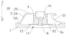
具体地,参照图1和图2,排气管20内限定出排气通道20a,排气通道20a具有进气口22a和出气口21a。例如,在图1和图2的示例中,进气口22a形成在排气通道20a的下端,出气口21a形成在排气通道20a的上端。在压缩机1000运行时,压缩机1000可以通过排气管20向外排气。Specifically, referring to FIGS. 1 and 2 , an
在本发明的描述中,需要理解的是,术语“中心”、“厚度”、“上”、“下”、“内”、“外”等指示的方位或位置关系为基于附图所示的方位或位置关系,仅是为了便于描述本发明和简化描述,而不是指示或暗示所指的装置或元件必须具有特定的方位、以特定的方位构造和操作,因此不能理解为对本发明的限制。In the description of the present invention, it should be understood that the orientations or positional relationships indicated by the terms "center", "thickness", "upper", "lower", "inner", "outer", etc. are based on those shown in the accompanying drawings The orientation or positional relationship is only for the convenience of describing the present invention and simplifying the description, rather than indicating or implying that the indicated device or element must have a specific orientation, be constructed and operated in a specific orientation, and therefore should not be construed as a limitation of the present invention.
单向阀10设在排气通道20a内,单向阀10在从进气口22a到出气口21a的方向上单向导通。The one-
由此,在压缩机1000工作时,单向阀10导通,排气管20的进气口22a和出气口21a连通,换热介质(例如冷媒等)经排气管20排至压缩机1000外,实现制冷装置的正常循环。在压缩机1000停止工作时,单向阀10断开,排气管20的进气口22a和出气口21a不再连通,此时,排气管20内的换热介质无法进入压缩机1000内部,利于压缩机1000快速地实现压力平衡,满足快速重启的要求。同时,可以避免压缩机1000内的冷媒发生沉积,从而可以避免压缩机1000底部油池溶解过多冷媒导致的润滑油粘度下降,进而可以在压缩机1000再次启动时,避免压缩机1000内部的润滑油粘度下降可能导致的异常磨损,提高了压缩机1000的可靠性。Therefore, when the
根据本发明实施例的用于压缩机1000的排气管组件100,通过在排气管20内设置单向阀10,使单向阀10从进气口22a到出气口21a单向导通,由此,在压缩机1000处于工作状态时,换热介质能够正常循环,且在压缩机1000停止工作后,排气管20内的换热介质不会逆流,有利于压缩机1000快速地实现压力平衡,满足快速重启的要求。同时,可以避免压缩机1000内的冷媒发生沉积,避免异常磨损,有利于提高压缩机1000的可靠性。此外,还可以减小热量损失,提高制冷装置的运行效率。According to the
根据本发明的一些实施例,排气管20包括第一管段21和第二管段22,出气口21a形成在第一管段21的一端,第二管段22的一端与第一管段21的另一端相连,进气口22a形成在第二管段22的另一端,单向阀10设在第二管段22内。According to some embodiments of the present invention, the exhaust pipe 20 includes a
参照图1和图2,第二管段22连接在第一管段21的下端,出气口21a形成在第一管段21的上端,进气口22a形成在第二管段22的下端。由此,通过将排气管20设置为彼此相连的第一管段21和第二管段22,并将单向阀10设置在第二管段22内,便于单向阀10的安装,可以降低单向阀10的安装难度,提高安装效率。1 and 2 , the
根据本发明的一些实施例,第二管段22的上述一端(例如,图1中的上端)形成有台阶部211,第一管段21的另一端(例如,图1中的下端)固定在台阶部211上。由此,可以方便地实现第一管段21和第二管段22的连接,使得排气管组件100的装配更加简便易行,易于安装使用。According to some embodiments of the present invention, the above-mentioned one end (eg, the upper end in FIG. 1 ) of the
根据本发明的一些实施例,第二管段22的内壁上设有朝向第二管段22的外壁凹入的凹槽22b,单向阀10固定在凹槽22b内。可选地,凹槽22b可以形成为环形。由此,可以将单向阀10方便且牢靠地安装在第二管段22内,降低了单向阀10的装配难度,提高了安装效率。According to some embodiments of the present invention, the inner wall of the
在本发明的一些实施例中,第二管段22包括彼此相连的主体段221和连接段222,其中,连接段222设在主体段221的上方。连接段222与第一管段21相连,单向阀10设在主体段221内,主体段221的横截面积大于连接段222的横截面积。由此,可以进一步地降低单向阀10的装配难度,提高安装效率。In some embodiments of the present invention, the
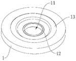
根据本发明的一些实施例,单向阀10包括:阀座1、限位器2、阀芯3和弹性元件4。其中,阀座1与排气管20的内壁相连,且阀座1将排气通道20a分隔为第一通道201和第二通道202,第一通道201与进气口22a连通,第二通道202与出气口21a连通,阀座1上设有贯通的入口11。参照图4-图9,入口11形成为在阀座1的厚度方向上贯穿阀座1的贯通口。According to some embodiments of the present invention, the one-
限位器2与阀座1相连,限位器2与阀座1之间限定出阀腔2a,入口11与阀腔2a连通,限位器2上设有与阀腔2a连通的出口21。阀芯3设在阀腔2a内且在第一位置和第二位置之间可移动,其中,在第一位置时,阀芯3关闭入口11。在第二位置时,阀芯3打开入口11以使第一通道201与第二通道202连通,且在第二位置时,阀芯3与限位器2止抵配合。在第二位置时,由于阀芯3与限位器2止抵配合,从而可以通过限位器2限制阀芯3继续运动。弹性元件4连接在阀芯3和限位器2之间以常驱动阀芯3关闭入口11。The
其中,在第一位置时,阀芯3关闭入口11,此时阀芯3的入口11和出口21不连通,从而第一通道201和第二通道202不连通,此时,换热介质无法从排气管20的进气口22a流向出气口21a。在第二位置时,阀芯3打开入口11,阀芯3的入口11和出口21连通,从而第一通道201和第二通道202连通,此时,换热介质可以从排气管20的进气口22a流向出气口21a。Among them, in the first position, the
由此,在该排气管组件100应用于制冷装置时,在制冷装置停止工作时,压缩机1000停机,阀芯3下部与阀芯3上部的气体压差力小于弹性元件4的弹力,此时阀芯3在弹性元件4的弹性压力作用下移动至第一位置以关闭入口11,排气通道20a的第一通道201和第二通道202互不连通,排气管20内的换热介质无法流向压缩机1000内部,由此,有利于压缩机1000快速地实现压力平衡,满足快速重启的要求。同时,可以避免压缩机1000内的冷媒发生沉积,避免异常磨损,有利于提高压缩机1000的可靠性。Therefore, when the
在压缩机1000工作时,阀芯3下端的气体压力较大,当阀芯3下部与阀芯3上部的气体压差力大于弹性元件4的弹力(忽略阀芯3及弹性元件4的重力)时,弹性元件4被压缩,第二通道202内的压力推动阀芯3移动至第二位置以打开阀座1上的入口11,且在第二位置时阀芯3与限位器2止抵配合以限制阀芯3继续朝向远离入口11的方向移动,起到对阀芯3的限位作用,第一通道201和第二通道202连通,进入排气通道20a内的换热介质通过阀座1上的入口11流向出气口21a,从排气管20排出,使换热介质能够正常循环,进而使得制冷装置可以正常工作。When the
同时,由于本申请中的单向阀10通过弹性元件4驱动阀芯3运动,属于全机械式控制,结构简单,体积小且稳定性和可靠性高。At the same time, because the one-
根据本发明的一些实施例,阀芯3包括:阀块31和阀片32,弹性元件4套设在阀块31外。可选地,弹性元件4可以为弹簧。阀片32设在阀块31的邻近阀座1一端(例如,图5中的下端),在第一位置时,阀片32关闭入口11,在第二位置时,阀片32打开入口11。由此,通过将阀芯3设置成包括阀块31和阀片32的结构,使得阀芯3的结构简单,且方便阀芯3打开和关闭入口11。According to some embodiments of the present invention, the
在本发明的一些实施例中,阀片32形成为平板状或片状。由此,可以减小单向阀10的整体体积,减小单向阀10的占用空间,便于单向阀10的安装使用。In some embodiments of the present invention, the
可选地,阀片32的形状可以与入口11的形状相适配。例如,当入口11形成为圆形孔时,阀片32可以形成为圆形。结构简单,加工方便,且便于实现阀片32对入口11的密封。Optionally, the shape of the
根据本发明的一些实施例,阀座1上设有凸起部12,凸起部12环绕在入口11的外周,在第一位置时,阀片32与凸起部12止抵配合以形成面面密封或线线密封。这样,可保证阀片32与阀座1具有较大的接触面积,使得二者有效密封,防止换热介质逆流。According to some embodiments of the present invention, the
例如,在本发明的一些实施例中,参照图9和图10,凸起部12的外周面形成为弧形面,此时凸起部12与阀片32之间形成线线密封。具体地,当凸起部12形成为圆环形时,凸起部12与阀片32之间的配合处形成为圆形。For example, in some embodiments of the present invention, referring to FIG. 9 and FIG. 10 , the outer peripheral surface of the
又如,在本发明的另一些实施例中,参照图11,凸起部12的外周面包括平坦面,且平坦面与阀片32止抵接触。此时凸起部12与阀片32之间形成面面密封。可选地,平坦面的宽度B满足:0.1mm≤B≤0.8mm。例如,B可以进一步满足:B=0.1mm、B=0.2mm、B=0.3mm、B=0.4mm、B=0.5mm、B=0.6mm、B=0.7mm、B=0.8mm等。由此,可以提高阀片32与阀座1的密封效果。For another example, in other embodiments of the present invention, referring to FIG. 11 , the outer peripheral surface of the protruding
可以理解的是,平坦面的宽度为平坦面的外端与内端之间的间距。例如,当平坦面形成为环形面时,平坦面的宽度为平坦面的外径与内径之差。It can be understood that the width of the flat surface is the distance between the outer end and the inner end of the flat surface. For example, when the flat surface is formed as an annular surface, the width of the flat surface is the difference between the outer diameter and the inner diameter of the flat surface.
根据本发明的一些实施例,凸起部12与阀片32的配合处与阀片32的外端之间的最小距离d满足:d≥0.5mm。例如,d可以进一步满足:d=0.6mm、d=0.7mm、d=0.8mm等。由此,可以提高阀片32与阀座1的密封效果。According to some embodiments of the present invention, the minimum distance d between the fitting position of the protruding
根据本发明的一些实施例,阀片32通过螺钉5或铆钉6与阀块31相连。例如,在图5和图6的示例中,阀片32通过螺钉5与阀块31相连。在图7的示例中,阀片32通过铆钉6与阀块31相连。结构简单,且连接可靠。According to some embodiments of the present invention, the
具体地,参照图12,阀片32上形成有贯通的安装孔321,螺钉5或铆钉6可以穿过安装孔321与阀片32连接。Specifically, referring to FIG. 12 , a through mounting
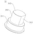
根据本发明的一些实施例,阀块31包括彼此相连的安装段311和导向段312,弹性元件4套设在安装段311上,限位器2上设有导向孔22,导向段312适于伸入导向孔22内与导向孔22配合,安装段311的横截面大于导向孔22的横截面。由此,阀芯3在移动过程中,通过导向段312与导向孔22配合,可以对阀芯3进行导向,减小阀芯3移动过程中的摇摆及窜动,降低气体流动损失。同时,由于安装段311的横截面大于导向孔22的横截面,在阀芯3移动至第二位置时,安装段311可以与限位器2的内壁面止抵配合以限制阀芯3继续移动。According to some embodiments of the present invention, the
可选地,在阀芯3位于第一位置时,导向段312的上端伸出导向孔22,由此,可以保证导向效果。Optionally, when the
根据本发明的一些实施例,导向孔22与导向段312之间的配合间隙H1满足:0.1mm≤H1≤0.5mm。可以理解的是,当导向孔22与导向段312之间的配合间隙过小时,导向段312进入导向孔22时容易卡死,从而引起单向阀10失效,若导向孔22与导向段312之间的配合间隙过大,则导向作用不明显,导向处进入限位孔时摇摆及窜动明显,一方面会引起异常噪音,另一方面气体流动损失较大。在导向孔22与导向段312之间的配合间隙H1满足:0.1mm≤H1≤0.5mm时,导向作用最优且不会引起单向阀10动作时的异常噪音。According to some embodiments of the present invention, the fitting clearance H1 between the
根据本发明的一些实施例,弹性元件4与安装段311过盈配合。例如,弹性元件4与安装段311之间的配合间隙H2满足:0<H2≤0.4mm。在本发明的一些实施中,安装段311的外径为内径为D1,弹性元件4的安装内径为D2,H2=D1-D2。由此,可保证弹性元件4与安装段311的过盈配合,利于弹性元件4的安装的同时,减小弹性元件4的变形。According to some embodiments of the present invention, the
根据本发明的一些实施例,导向段312的外周面包括两个沿导向段312的轴向延伸平面313,两个平面313相对于导向段312的中心轴线对称。由此,在装配过程中,有利于螺钉5的固定拧紧。According to some embodiments of the present invention, the outer peripheral surface of the
根据本发明的一些实施例,限位器2包括:限位板23、侧板24和安装板25。侧板24连接在限位板23的外周,安装板25设在侧板24上,且安装板25适于与阀座1相连。结构简单,加工方便。According to some embodiments of the present invention, the
根据本发明的一些实施例,限位板23上设有至少一个出口21。也就是说,限位板23上设有一个或者多个出口21。出口21可以形成为圆形孔、腰形孔或异形孔。在本发明的描述中,“多个”的含义是两个或两个以上。由此,可以减小气流在限位器2内形成的漩涡,从而减小流动损失。According to some embodiments of the present invention, the limiting
根据本发明的一些实施例,侧板24上设有至少一个出口21。也就是说,侧板24上设有一个或者多个出口21。由此,在限位板23及侧板24上均设置有出口21,能明显减小气流在限位器2内形成的漩涡,从而减小流动损失。According to some embodiments of the present invention, the
可选地,在本发明的一些实施例中,限位板23上设有三个出口21,侧板24上设有三个出口21。其中,限位板23上的三个出口21在导向孔22的周向上间隔开设置,侧板24上的三个出口21在侧板24的周向上间隔设置。由此,可以明显减小气流在限位器2内形成的漩涡,从而减小流动损失。Optionally, in some embodiments of the present invention, the limiting
根据本发明的一些实施例,阀座1上设有安装槽13,安装板25固定在安装槽13内。由此,可以将限位器2方便且牢靠地安装在阀座1上,降低了单向阀10的装配难度,提高了安装效率。According to some embodiments of the present invention, the
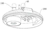
如图17所示,根据本发明第二方面实施例的用于压缩机1000的壳体组件200,包括:壳体30和排气管组件100,壳体30内具有容纳腔30a,排气管组件100为根据本发明上述第一方面实施例的排气管组件100,排气管组件100设在壳体30上,进气口22a与容纳腔30a连通。其中,壳体30可以为压缩机1000的上壳体30。As shown in FIG. 17 , the
根据本发明第二方面实施例的用于压缩机1000的壳体组件200,通过在排气管20内设置单向阀10,使单向阀10从进气口22a到出气口21a单向导通,由此,在压缩机1000处于工作状态时,换热介质能够正常循环,且在压缩机1000停止工作后,排气管20内的换热介质不会逆流,有利于压缩机1000快速地实现压力平衡,满足快速重启的要求。同时,可以避免压缩机1000内的冷媒发生沉积,避免异常磨损,有利于提高压缩机1000的可靠性。According to the
根据本发明的一些实施例,壳体组件200还包括工艺管40,工艺管40设在壳体30上,工艺管40具有连通腔,连通腔与容纳腔30a连通。在生产时,工艺管40可以用于封油、抽真空等生产工序。由此,有利于壳体组件200的加工。According to some embodiments of the present invention, the
可选地,工艺管40的中心轴线可以与壳体30的中心轴线重合。由此,可以提高壳体30的整体美观性。Alternatively, the central axis of the
根据本发明实施例的壳体组件200的其他构成例如接线端子等以及操作对于本领域普通技术人员而言都是已知的,这里不再详细描述。Other components of the
如图18所示,根据本发明第三方面实施例的压缩机1000,包括根据本发明上述第二方面实施例的用于压缩机1000的壳体组件200。As shown in FIG. 18 , the
根据本发明第三方面实施例的压缩机1000,通过设置根据本发明上述第二方面实施例的用于压缩机1000的壳体组件200,在排气管20内设置了单向阀10,使单向阀10从进气口22a到出气口21a单向导通,由此,在压缩机1000处于工作状态时,换热介质能够正常循环,且在压缩机1000停止工作后,排气管20内的换热介质不会逆流,有利于压缩机1000快速地实现压力平衡,满足快速重启的要求。同时,可以避免压缩机1000内的冷媒发生沉积,避免异常磨损,有利于提高压缩机1000的可靠性。According to the
根据本发明实施例的压缩机1000的其他构成例如压缩机构、储液器300等以及操作对于本领域普通技术人员而言都是已知的,这里不再详细描述。Other components of the
根据本发明第四方面实施例的制冷装置,包括根据本发明上述第三方面实施例的压缩机1000。The refrigeration apparatus according to the embodiment of the fourth aspect of the present invention includes the
根据本发明第四方面实施例的制冷装置,通过设置根据本发明上述第三方面实施例的压缩机1000,有利于压缩机1000快速地实现压力平衡,满足快速重启的要求。同时,可以避免压缩机1000内的冷媒发生沉积,避免异常磨损,有利于提高压缩机1000的可靠性。According to the refrigeration device of the fourth aspect of the present invention, by providing the
根据本发明实施例的制冷装置的其他构成以及操作对于本领域普通技术人员而言都是已知的,这里不再详细描述。Other structures and operations of the refrigeration apparatus according to the embodiments of the present invention are known to those of ordinary skill in the art, and will not be described in detail here.
在本说明书的描述中,参考术语“一个实施例”、“一些实施例”、“示意性实施例”、“示例”、“具体示例”、或“一些示例”等的描述意指结合该实施例或示例描述的具体特征、结构、材料或者特点包含于本发明的至少一个实施例或示例中。在本说明书中,对上述术语的示意性表述不一定指的是相同的实施例或示例。而且,描述的具体特征、结构、材料或者特点可以在任何的一个或多个实施例或示例中以合适的方式结合。In the description of this specification, reference to the terms "one embodiment," "some embodiments," "exemplary embodiment," "example," "specific example," or "some examples", etc., is meant to incorporate the embodiments A particular feature, structure, material, or characteristic described by an example or example is included in at least one embodiment or example of the present invention. In this specification, schematic representations of the above terms do not necessarily refer to the same embodiment or example. Furthermore, the particular features, structures, materials or characteristics described may be combined in any suitable manner in any one or more embodiments or examples.
尽管已经示出和描述了本发明的实施例,本领域的普通技术人员可以理解:在不脱离本发明的原理和宗旨的情况下可以对这些实施例进行多种变化、修改、替换和变型,本发明的范围由权利要求及其等同物限定。Although embodiments of the present invention have been shown and described, it will be understood by those of ordinary skill in the art that various changes, modifications, substitutions and alterations can be made in these embodiments without departing from the principles and spirit of the invention, The scope of the invention is defined by the claims and their equivalents.
Claims (20)
Priority Applications (1)
| Application Number | Priority Date | Filing Date | Title |
|---|---|---|---|
| CN202010078991.0ACN111237193A (en) | 2020-02-03 | 2020-02-03 | Discharge pipe assemblies, housing assemblies, compressors and refrigeration units for compressors |
Applications Claiming Priority (1)
| Application Number | Priority Date | Filing Date | Title |
|---|---|---|---|
| CN202010078991.0ACN111237193A (en) | 2020-02-03 | 2020-02-03 | Discharge pipe assemblies, housing assemblies, compressors and refrigeration units for compressors |
Publications (1)
| Publication Number | Publication Date |
|---|---|
| CN111237193Atrue CN111237193A (en) | 2020-06-05 |
Family
ID=70879842
Family Applications (1)
| Application Number | Title | Priority Date | Filing Date |
|---|---|---|---|
| CN202010078991.0APendingCN111237193A (en) | 2020-02-03 | 2020-02-03 | Discharge pipe assemblies, housing assemblies, compressors and refrigeration units for compressors |
Country Status (1)
| Country | Link |
|---|---|
| CN (1) | CN111237193A (en) |
Cited By (4)
| Publication number | Priority date | Publication date | Assignee | Title |
|---|---|---|---|---|
| CN111173712A (en)* | 2020-02-03 | 2020-05-19 | 广东美芝制冷设备有限公司 | Check Valves, Compressors and Refrigeration Units |
| WO2022170932A1 (en)* | 2021-02-10 | 2022-08-18 | 浙江盾安人工环境股份有限公司 | Liquid accumulator and refrigerating system having same |
| CN116255326A (en)* | 2021-12-09 | 2023-06-13 | 广东美芝制冷设备有限公司 | One-way valve for compressor assembly, compressor and liquid reservoir |
| CN116263160A (en)* | 2021-12-14 | 2023-06-16 | 广东美芝制冷设备有限公司 | Discharge check valve for compressor and compressor having same |
Citations (11)
| Publication number | Priority date | Publication date | Assignee | Title |
|---|---|---|---|---|
| CN201532049U (en)* | 2009-02-05 | 2010-07-21 | 艾默生环境优化技术有限公司 | Flash tank and vortex compressor and refrigeration/heat pump system employing same |
| CN202360337U (en)* | 2011-11-10 | 2012-08-01 | 麦克维尔空调制冷(苏州)有限公司 | Reversion-proof mechanism for stopping of refrigeration compressor |
| CN204647444U (en)* | 2015-02-27 | 2015-09-16 | 陕西法士特齿轮有限责任公司 | A kind of hydrodynamic retarding organ pipe connects angle check valve |
| CN206268061U (en)* | 2016-11-23 | 2017-06-20 | 上海申贝泵业制造有限公司 | One kind metering pump hydraulic end |
| CN106949269A (en)* | 2017-03-30 | 2017-07-14 | 陕西航天动力高科技股份有限公司 | The double flexible pipe membrane pump check valves of high pressure and unidirectional valve group |
| CN107690526A (en)* | 2015-06-11 | 2018-02-13 | 比泽尔制冷设备有限公司 | Annular solder mask in discharge check valve |
| CN207921412U (en)* | 2017-12-29 | 2018-09-28 | 赛威隆机电设备河北有限公司 | A kind of minute-pressure startup check valve |
| CN209743161U (en)* | 2019-04-10 | 2019-12-06 | 广东美芝制冷设备有限公司 | High back pressure type compressor and refrigeration cycle system with same |
| CN111173712A (en)* | 2020-02-03 | 2020-05-19 | 广东美芝制冷设备有限公司 | Check Valves, Compressors and Refrigeration Units |
| CN212003599U (en)* | 2020-02-03 | 2020-11-24 | 广东美芝制冷设备有限公司 | Exhaust pipe assembly for compressor, shell assembly, compressor and refrigerating device |
| CN212003513U (en)* | 2020-02-03 | 2020-11-24 | 广东美芝制冷设备有限公司 | Check valve, compressor and refrigerating plant |
- 2020
- 2020-02-03CNCN202010078991.0Apatent/CN111237193A/enactivePending
Patent Citations (11)
| Publication number | Priority date | Publication date | Assignee | Title |
|---|---|---|---|---|
| CN201532049U (en)* | 2009-02-05 | 2010-07-21 | 艾默生环境优化技术有限公司 | Flash tank and vortex compressor and refrigeration/heat pump system employing same |
| CN202360337U (en)* | 2011-11-10 | 2012-08-01 | 麦克维尔空调制冷(苏州)有限公司 | Reversion-proof mechanism for stopping of refrigeration compressor |
| CN204647444U (en)* | 2015-02-27 | 2015-09-16 | 陕西法士特齿轮有限责任公司 | A kind of hydrodynamic retarding organ pipe connects angle check valve |
| CN107690526A (en)* | 2015-06-11 | 2018-02-13 | 比泽尔制冷设备有限公司 | Annular solder mask in discharge check valve |
| CN206268061U (en)* | 2016-11-23 | 2017-06-20 | 上海申贝泵业制造有限公司 | One kind metering pump hydraulic end |
| CN106949269A (en)* | 2017-03-30 | 2017-07-14 | 陕西航天动力高科技股份有限公司 | The double flexible pipe membrane pump check valves of high pressure and unidirectional valve group |
| CN207921412U (en)* | 2017-12-29 | 2018-09-28 | 赛威隆机电设备河北有限公司 | A kind of minute-pressure startup check valve |
| CN209743161U (en)* | 2019-04-10 | 2019-12-06 | 广东美芝制冷设备有限公司 | High back pressure type compressor and refrigeration cycle system with same |
| CN111173712A (en)* | 2020-02-03 | 2020-05-19 | 广东美芝制冷设备有限公司 | Check Valves, Compressors and Refrigeration Units |
| CN212003599U (en)* | 2020-02-03 | 2020-11-24 | 广东美芝制冷设备有限公司 | Exhaust pipe assembly for compressor, shell assembly, compressor and refrigerating device |
| CN212003513U (en)* | 2020-02-03 | 2020-11-24 | 广东美芝制冷设备有限公司 | Check valve, compressor and refrigerating plant |
Cited By (6)
| Publication number | Priority date | Publication date | Assignee | Title |
|---|---|---|---|---|
| CN111173712A (en)* | 2020-02-03 | 2020-05-19 | 广东美芝制冷设备有限公司 | Check Valves, Compressors and Refrigeration Units |
| WO2022170932A1 (en)* | 2021-02-10 | 2022-08-18 | 浙江盾安人工环境股份有限公司 | Liquid accumulator and refrigerating system having same |
| CN116255326A (en)* | 2021-12-09 | 2023-06-13 | 广东美芝制冷设备有限公司 | One-way valve for compressor assembly, compressor and liquid reservoir |
| WO2023103194A1 (en)* | 2021-12-09 | 2023-06-15 | 广东美芝制冷设备有限公司 | One-way valve for compressor assembly, compressor, and liquid storage device |
| CN116263160A (en)* | 2021-12-14 | 2023-06-16 | 广东美芝制冷设备有限公司 | Discharge check valve for compressor and compressor having same |
| WO2023108924A1 (en)* | 2021-12-14 | 2023-06-22 | 广东美芝制冷设备有限公司 | Exhaust one-way valve for compressor, and compressor having same |
Similar Documents
| Publication | Publication Date | Title |
|---|---|---|
| CN111237193A (en) | Discharge pipe assemblies, housing assemblies, compressors and refrigeration units for compressors | |
| US8585372B2 (en) | Motor/pump assembly | |
| CN212003599U (en) | Exhaust pipe assembly for compressor, shell assembly, compressor and refrigerating device | |
| CN111173712A (en) | Check Valves, Compressors and Refrigeration Units | |
| US5607287A (en) | Reciprocating piston type compressor with an improved discharge valve mechanism | |
| CN212003513U (en) | Check valve, compressor and refrigerating plant | |
| WO2020119191A1 (en) | Compressor and refrigerating device having same | |
| MY134396A (en) | High-low pressure dome type compressor | |
| KR20110013444A (en) | Release valve device for hermetic compressor | |
| CN110645165B (en) | Cylinder head assembly, compressor and refrigerating device | |
| US20220299026A1 (en) | Vapor injection device and compressor | |
| US8770088B2 (en) | Reciprocating compressor | |
| CN217873259U (en) | Discharge check valve assemblies, scroll compressors and air conditioning systems | |
| WO2022016934A1 (en) | Compressor and air conditioner | |
| WO2021128905A1 (en) | Pump body assembly and variable capacity compressor | |
| CN111238097A (en) | Liquid storage device, compressor and refrigerating device | |
| JP2006177167A (en) | Discharge side structure and check valve used for it | |
| CN118346606B (en) | Scroll compressor having a rotor with a rotor shaft having a rotor shaft with a | |
| CN218030640U (en) | Scroll compressor having a plurality of scroll members | |
| CN212006320U (en) | Liquid storage device, compressor and refrigerating device | |
| CN115164456A (en) | Air-supplementing enthalpy-increasing pipe mechanism, compression device and air conditioning equipment | |
| CN209704844U (en) | compressor | |
| CN223075732U (en) | Noise reduction box structure, pump body noise reduction assembly and cold storage equipment | |
| CN207513827U (en) | Screw compressor and air conditioner | |
| CN111396313A (en) | Air conditioner, compressor assembly, compressor and pump body unit thereof |
Legal Events
| Date | Code | Title | Description |
|---|---|---|---|
| PB01 | Publication | ||
| PB01 | Publication | ||
| SE01 | Entry into force of request for substantive examination | ||
| SE01 | Entry into force of request for substantive examination |