CN111237182A - A fault diagnosis system for an air conditioner compressor - Google Patents
A fault diagnosis system for an air conditioner compressorDownload PDFInfo
- Publication number
- CN111237182A CN111237182ACN201811513951.3ACN201811513951ACN111237182ACN 111237182 ACN111237182 ACN 111237182ACN 201811513951 ACN201811513951 ACN 201811513951ACN 111237182 ACN111237182 ACN 111237182A
- Authority
- CN
- China
- Prior art keywords
- resistor
- vibration
- compressor
- operational amplifier
- integrated operational
- Prior art date
- Legal status (The legal status is an assumption and is not a legal conclusion. Google has not performed a legal analysis and makes no representation as to the accuracy of the status listed.)
- Pending
Links
- 238000003745diagnosisMethods0.000titleclaimsabstractdescription24
- 238000012545processingMethods0.000claimsabstractdescription66
- 238000007405data analysisMethods0.000claimsabstractdescription40
- 230000005540biological transmissionEffects0.000claimsabstractdescription33
- 238000012544monitoring processMethods0.000claimsabstractdescription10
- 239000003990capacitorSubstances0.000claimsdescription39
- 238000001914filtrationMethods0.000claimsdescription21
- 238000004378air conditioningMethods0.000claimsdescription20
- 230000003321amplificationEffects0.000claimsdescription5
- 238000003199nucleic acid amplification methodMethods0.000claimsdescription5
- 230000001133accelerationEffects0.000claimsdescription3
- 238000004458analytical methodMethods0.000claimsdescription3
- 230000007175bidirectional communicationEffects0.000claimsdescription3
- 230000006835compressionEffects0.000claims2
- 238000007906compressionMethods0.000claims2
- 238000012360testing methodMethods0.000description10
- 238000010586diagramMethods0.000description4
- 238000002955isolationMethods0.000description3
- 238000001514detection methodMethods0.000description2
- 238000005259measurementMethods0.000description2
- 238000000034methodMethods0.000description2
- 230000009286beneficial effectEffects0.000description1
- 238000001816coolingMethods0.000description1
- 230000008878couplingEffects0.000description1
- 238000010168coupling processMethods0.000description1
- 238000005859coupling reactionMethods0.000description1
- 238000010438heat treatmentMethods0.000description1
- 239000007788liquidSubstances0.000description1
- 238000012986modificationMethods0.000description1
- 230000004048modificationEffects0.000description1
- 238000004088simulationMethods0.000description1
- 238000010998test methodMethods0.000description1
Images


Classifications
- F—MECHANICAL ENGINEERING; LIGHTING; HEATING; WEAPONS; BLASTING
- F04—POSITIVE - DISPLACEMENT MACHINES FOR LIQUIDS; PUMPS FOR LIQUIDS OR ELASTIC FLUIDS
- F04B—POSITIVE-DISPLACEMENT MACHINES FOR LIQUIDS; PUMPS
- F04B51/00—Testing machines, pumps, or pumping installations
- F—MECHANICAL ENGINEERING; LIGHTING; HEATING; WEAPONS; BLASTING
- F04—POSITIVE - DISPLACEMENT MACHINES FOR LIQUIDS; PUMPS FOR LIQUIDS OR ELASTIC FLUIDS
- F04B—POSITIVE-DISPLACEMENT MACHINES FOR LIQUIDS; PUMPS
- F04B39/00—Component parts, details, or accessories, of pumps or pumping systems specially adapted for elastic fluids, not otherwise provided for in, or of interest apart from, groups F04B25/00 - F04B37/00
Landscapes
- Engineering & Computer Science (AREA)
- Mechanical Engineering (AREA)
- General Engineering & Computer Science (AREA)
- Measurement Of Mechanical Vibrations Or Ultrasonic Waves (AREA)
Abstract
Description
Translated fromChinese技术领域technical field
本发明涉及智能测试领域,尤其涉及一种空调压缩机故障诊断系统。The invention relates to the field of intelligent testing, in particular to a fault diagnosis system for an air conditioner compressor.
背景技术Background technique
在对压缩机本体振动进行评价或提取压缩机振动载荷进行管路系统CAE有限元仿真时,需要测试压缩机在各个工作频率点的振动值,但是目前并没有一种有效的空调器压缩机振动测试系统。企业里通常的做法是在空调系统运行时直接测试压缩机表面的振动,由于压缩机的管路系统为复杂的空间结构,存在较多的固有频率,容易与压缩机工作频率重合产生共振,从而反过来影响压缩机的振动,导致测试结果极不准确。还有的测试方法是测试压缩机单体空载或引入替代系统时的振动,这种方法存在的问题是测试系统的负载与压缩机实际工作的负载不相同,因此难以评估压缩机在工作载荷下的实际振动情况,如何准确地、快速地测试空调器压缩机在空调系统负载下的振动,是空调系统开发人员关注的重要问题。When evaluating the vibration of the compressor body or extracting the compressor vibration load for CAE finite element simulation of the pipeline system, it is necessary to test the vibration value of the compressor at each operating frequency point, but there is currently no effective air conditioner compressor vibration value. test system. The usual practice in the enterprise is to directly test the vibration of the compressor surface when the air-conditioning system is running. Because the pipeline system of the compressor is a complex spatial structure, there are many natural frequencies, which are easy to overlap with the compressor operating frequency and cause resonance, thus This in turn affects the vibration of the compressor, resulting in highly inaccurate test results. Another test method is to test the vibration of the compressor unit with no load or when an alternative system is introduced. The problem with this method is that the load of the test system is not the same as the actual working load of the compressor, so it is difficult to evaluate the working load of the compressor. How to accurately and quickly test the vibration of the air conditioner compressor under the load of the air conditioning system is an important issue for air conditioning system developers.
发明内容SUMMARY OF THE INVENTION
因此,为了解决上述问题,本发明提供一种空调压缩机故障诊断系统,利用压缩机、排气管、排气管防振软管、吸气管、吸气管防振软管、四通阀、蒸发器、冷凝器、中央处理器、振动监测模块、信号处理电路、无线传输模块、显示模块、存储模块以及数据分析模块对空调压缩机的振动信号进行监测,振动传感器设置于压缩机的吸气管口和排气管口处的x、y、z三个方向,并通过数据分析模块计算压缩机x方向的振动值、y方向的振动值、z方向的振动值、压缩机吸气管口处的振动值以及压缩机排气管口处的振动值,并将计算得到的上述振动值分别与数据分析模块内的预设阈值进行比较,以对空调压缩机故障进行诊断。Therefore, in order to solve the above problems, the present invention provides a fault diagnosis system for an air conditioner compressor, which utilizes a compressor, an exhaust pipe, an anti-vibration hose for the exhaust pipe, a suction pipe, an anti-vibration hose for the suction pipe, and a four-way valve. , evaporator, condenser, central processing unit, vibration monitoring module, signal processing circuit, wireless transmission module, display module, storage module and data analysis module to monitor the vibration signal of the air-conditioning compressor, and the vibration sensor is arranged on the suction side of the compressor. The three directions of x, y, and z at the air pipe mouth and the exhaust pipe mouth are calculated by the data analysis module. The vibration value of the compressor in the x direction, the vibration value in the y direction, the vibration value in the z direction, and the compressor suction pipe The vibration value at the outlet and the vibration value at the outlet of the compressor exhaust pipe are compared, and the calculated vibration value is compared with the preset threshold value in the data analysis module to diagnose the fault of the air conditioner compressor.
根据本发明的一种空调压缩机故障诊断系统,其包括压缩机、排气管、排气管防振软管、吸气管、吸气管防振软管、四通阀、蒸发器、冷凝器、中央处理器、振动监测模块、信号处理电路、无线传输模块、显示模块、存储模块以及数据分析模块。A fault diagnosis system for an air conditioner compressor according to the present invention includes a compressor, an exhaust pipe, an anti-vibration hose for the exhaust pipe, a suction pipe, an anti-vibration hose for the suction pipe, a four-way valve, an evaporator, a condenser controller, central processing unit, vibration monitoring module, signal processing circuit, wireless transmission module, display module, storage module and data analysis module.
其中,压缩机的排气管口通过排气管与四通阀连接,压缩机的吸气管口通过吸气管与四通阀连接,排气管防振软管套设于排气管上,吸气管防振软管套设于吸气管上,四通阀与蒸发器连接,四通阀还与冷凝器连接,蒸发器与冷凝器连接,振动监测模块包括若干个设置于压缩机的排气管口和吸气管口处的振动传感器,振动传感器与信号处理电路的输入端连接,信号处理电路的输出端与中央处理器的输入端连接,显示模块的输入端与存储模块的输入端均与中央处理器的输出端连接,中央处理器的输出端与无线传输模块的输入端连接,数据分析模块与无线传输模块双向通讯连接,无线传输模块的输出端还与显示模块的输入端连接。Among them, the exhaust pipe port of the compressor is connected with the four-way valve through the exhaust pipe, the suction pipe port of the compressor is connected with the four-way valve through the suction pipe, and the anti-vibration hose of the exhaust pipe is sleeved on the exhaust pipe , the anti-vibration hose of the suction pipe is sleeved on the suction pipe, the four-way valve is connected to the evaporator, the four-way valve is also connected to the condenser, and the evaporator is connected to the condenser. The vibration sensor at the exhaust pipe mouth and the suction pipe mouth is connected with the input end of the signal processing circuit, the output end of the signal processing circuit is connected with the input end of the central processing unit, and the input end of the display module is connected with the input end of the storage module. The input end is connected with the output end of the central processing unit, the output end of the central processing unit is connected with the input end of the wireless transmission module, the data analysis module is connected with the wireless transmission module for bidirectional communication, and the output end of the wireless transmission module is also connected with the input end of the display module. end connection.
优选的是,振动传感器设置于压缩机的吸气管口和排气管口处的x、y、z三个方向。Preferably, the vibration sensors are arranged in three directions of x, y, and z at the inlet and outlet of the compressor.
优选的是,振动传感器用于检测空调压缩机吸气管口和排气管口的振动信号,将采集的振动信号转换为电压信号V0,并将电压信号V0传输至信号处理电路,V1为经过信号处理电路处理后的电压信号,信号处理电路包括信号放大单元和信号滤波单元,振动传感器的输出端与信号放大单元的输入端连接,信号放大单元的输出端与信号滤波单元的输入端连接,信号滤波单元的输出端与中央处理器的ADC端口连接。Preferably, the vibration sensor is used to detect the vibration signal of the air-conditioning compressor suction nozzle and the exhaust nozzle, convert the collected vibration signal into a voltage signal V0, and transmit the voltage signal V0 to the signal processing circuit, where V1 is a The voltage signal processed by the signal processing circuit, the signal processing circuit includes a signal amplifying unit and a signal filtering unit, the output end of the vibration sensor is connected with the input end of the signal amplifying unit, and the output end of the signal amplifying unit is connected with the input end of the signal filtering unit, The output end of the signal filtering unit is connected with the ADC port of the central processing unit.
优选的是,信号放大单元包括集成运放A1-A2、电阻R1-R14以及电容C1-C2。Preferably, the signal amplifying unit includes integrated operational amplifiers A1-A2, resistors R1-R14 and capacitors C1-C2.
其中,振动传感器的输出端与电阻R1的一端连接,电阻R3的一端接地,电阻R3的另一端与电阻R2的一端连接,电阻R1的另一端与电阻R2的另一端连接,电阻R1的另一端还与集成运放A1的同相输入端连接,电阻R3的另一端还与电阻R4的一端连接,电阻R4的另一端与集成运放A2的输出端连接,电阻R5的一端与集成运放A2的反相输入端连接,电阻R4的另一端还与电容C2的一端连接,电容C2的另一端与电阻R5的一端连接,电阻R6的一端与集成运放A2的同相输入端连接,电阻R6的另一端接地,电阻R7的一端接地,电阻R7的另一端与电阻R8的一端连接,电阻R8的另一端与集成运放A1的反相输入端连接,电阻R8的一端还与电容C1的一端连接,电阻R8的另一端还与电容C1的另一端连接,电阻R7的另一端还与电阻R9的一端连接,电阻R10的一端与集成运放A1的输出端连接,电阻R10的另一端与电阻R9的另一端连接,电阻R11的一端与电阻R12的一端连接,电阻R11的另一端与电阻R10的另一端连接,电阻R12的另一端与电阻R14的一端连接,电阻R5的另一端与电阻R13的一端连接,电阻R13的另一端与电阻R14的一端连接,电阻R14的另一端与信号滤波单元的输入端连接。The output end of the vibration sensor is connected to one end of the resistor R1, one end of the resistor R3 is grounded, the other end of the resistor R3 is connected to one end of the resistor R2, the other end of the resistor R1 is connected to the other end of the resistor R2, and the other end of the resistor R1 is connected It is also connected to the non-inverting input terminal of the integrated operational amplifier A1, the other end of the resistor R3 is also connected to one end of the resistor R4, the other end of the resistor R4 is connected to the output terminal of the integrated operational amplifier A2, and one end of the resistor R5 is connected to the integrated operational amplifier A2. The inverting input is connected, the other end of the resistor R4 is also connected to one end of the capacitor C2, the other end of the capacitor C2 is connected to one end of the resistor R5, the other end of the resistor R6 is connected to the non-inverting input of the integrated operational amplifier A2, and the other end of the resistor R6 is connected. One end is grounded, one end of resistor R7 is grounded, the other end of resistor R7 is connected to one end of resistor R8, the other end of resistor R8 is connected to the inverting input end of integrated operational amplifier A1, and one end of resistor R8 is also connected to one end of capacitor C1, The other end of the resistor R8 is also connected to the other end of the capacitor C1, the other end of the resistor R7 is also connected to one end of the resistor R9, one end of the resistor R10 is connected to the output end of the integrated operational amplifier A1, and the other end of the resistor R10 is connected to the resistor R9. The other end is connected, one end of resistor R11 is connected to one end of resistor R12, the other end of resistor R11 is connected to the other end of resistor R10, the other end of resistor R12 is connected to one end of resistor R14, the other end of resistor R5 is connected to one end of resistor R13 Connection, the other end of the resistor R13 is connected to one end of the resistor R14, and the other end of the resistor R14 is connected to the input end of the signal filtering unit.
优选的是,信号滤波单元包括电阻R15-R21、电容C3-C4以及集成运放A3-A5。Preferably, the signal filtering unit includes resistors R15-R21, capacitors C3-C4 and integrated operational amplifiers A3-A5.
其中,信号放大单元的输出端与电阻R15的一端连接,电阻R15的另一端与电阻R17的一端并联后与集成运放A3的同相输入端连接,电阻R17的另一端与集成运放A3的输出端连接,电阻R16的一端接地,电阻R16的另一端与电阻R21并联后与集成运放A3的同相输入端连接,电阻R21的另一端与集成运放A3的输出端连接,电阻R17的另一端与集成运放A3的输出端并联后与电阻R18的一端连接,电阻R18的另一端与电容C8的一端并联后与集成运放A4的反相输入端连接,电容C8的另一端与集成运放A4的输出端并联后与电阻R19的一端连接,集成运放A4的同相输入端接地,电阻R19的另一端与电容C9的一端并联后与集成运放A5的反相输入端连接,集成运放A5的同相输入端接地,电容C9的另一端与集成运放A5的输出端连接,电阻R20的一端与集成运放A3的反相输入端连接,电阻R20的另一端与集成运放A5的输出端连接,电阻R21的一端与集成运放A3的同相输入端连接,电阻R21的另一端与集成运放A4的输出端连接,集成运放A5的输出端与中央处理器的ADC端口连接,信号处理单元将处理后的电压信号V1传输至中央处理器的ADC端口。Among them, the output end of the signal amplification unit is connected to one end of the resistor R15, the other end of the resistor R15 is connected in parallel with one end of the resistor R17 and then connected to the non-inverting input end of the integrated operational amplifier A3, and the other end of the resistor R17 is connected to the output of the integrated operational amplifier A3 The other end of the resistor R16 is connected to the non-inverting input end of the integrated operational amplifier A3 after being connected in parallel with the resistor R21, the other end of the resistor R21 is connected to the output end of the integrated operational amplifier A3, and the other end of the resistor R17 is connected to the ground. It is connected in parallel with the output end of the integrated operational amplifier A3 and then connected to one end of the resistor R18. The other end of the resistor R18 is connected in parallel with one end of the capacitor C8 and then connected to the inverting input end of the integrated operational amplifier A4. The other end of the capacitor C8 is connected to the integrated operational amplifier. The output end of A4 is connected in parallel with one end of the resistor R19, the non-inverting input end of the integrated operational amplifier A4 is grounded, the other end of the resistor R19 is connected in parallel with one end of the capacitor C9 and then connected to the inverting input end of the integrated operational amplifier A5, the integrated operational amplifier The non-inverting input of A5 is grounded, the other end of capacitor C9 is connected to the output of integrated operational amplifier A5, one end of resistor R20 is connected to the inverting input of integrated operational amplifier A3, and the other end of resistor R20 is connected to the output of integrated operational amplifier A5 One end of the resistor R21 is connected to the non-inverting input end of the integrated operational amplifier A3, the other end of the resistor R21 is connected to the output end of the integrated operational amplifier A4, and the output end of the integrated operational amplifier A5 is connected to the ADC port of the central processing unit. The processing unit transmits the processed voltage signal V1 to the ADC port of the central processing unit.
优选的是,三个振动传感器分别设置于压缩机的吸气管口处的x、y、z三个方向,三个传感器将测得的振动信号经过信号处理电路依次进行信号放大和滤波处理后测得压缩机的吸气管口处的x、y、z三个方向的振动值分别为A1、A2和A3,三个振动传感器分别设置于压缩机的排气管口处的x、y、z三个方向,三个传感器将测得的振动信号经过信号处理电路依次进行信号放大和滤波处理后测得压缩机的排气管口处的x、y、z三个方向的振动值分别为B1、B2和B3,中央处理器将接收到的振动值A1、A2、A3、B1、B2和B3传输至显示模块进行显示,中央处理器将接收到的振动值A1、A2、A3、B1、B2和B3传输至存储模块进行存储,中央处理器将接收到的振动值A1、A2、A3、B1、B2和B3通过无线传输模块传输至数据分析模块。Preferably, three vibration sensors are respectively arranged in three directions of x, y, and z at the suction nozzle of the compressor, and the three sensors amplify and filter the vibration signals measured by the signal processing circuit in turn. The vibration values of the three directions of x, y, and z at the suction pipe mouth of the compressor are measured as A1, A2 and A3, respectively. The three vibration sensors are respectively set at the x, y, and In the three directions of z, the three sensors amplify and filter the measured vibration signals through the signal processing circuit in turn, and then measure the vibration values in the three directions of x, y, and z at the outlet of the compressor. B1, B2 and B3, the central processing unit transmits the received vibration values A1, A2, A3, B1, B2 and B3 to the display module for display, and the central processing unit transmits the received vibration values A1, A2, A3, B1, B2 and B3 are transmitted to the storage module for storage, and the central processor transmits the received vibration values A1, A2, A3, B1, B2 and B3 to the data analysis module through the wireless transmission module.
优选的是,数据分析模块根据接收到的振动值A1、A2、A3、B1、B2和B3分析得压缩机x方向的振动值C1=A1+B1、y方向的振动值C2=A2+B2、z方向的振动值C3=A3+B3,数据分析模块将振动值C1与预设x方向振动阈值进行比较、振动值C2与预设y方向振动阈值进行比较以及振动值C3与预设z方向振动阈值进行比较,并将比较结果通过无线传输模块传输至显示模块进行显示。Preferably, the data analysis module analyzes the vibration value C1=A1+B1 in the x direction of the compressor according to the received vibration values A1, A2, A3, B1, B2 and B3, and the vibration value in the y direction C2=A2+B2, The vibration value C3=A3+B3 in the z direction, the data analysis module compares the vibration value C1 with the preset x-direction vibration threshold, the vibration value C2 compares with the preset y-direction vibration threshold, and the vibration value C3 and the preset z-direction vibration The threshold value is compared, and the comparison result is transmitted to the display module through the wireless transmission module for display.
优选的是,数据分析模块根据接收到的振动值A1、A2、A3、B1、B2和B3分析得压缩机吸气管口处的振动值D1为:Preferably, the data analysis module analyzes the vibration value D1 at the suction nozzle of the compressor according to the received vibration values A1, A2, A3, B1, B2 and B3 as:

分析得压缩机排气管口处的振动值D2为:According to the analysis, the vibration value D2 at the outlet of the compressor discharge pipe is:

数据分析模块将振动值D1与预设吸气管口处的振动阈值进行比较和振动值D2与预设排气管口处的振动阈值进行比较,并将比较结果通过无线传输模块传输至显示模块进行显示。The data analysis module compares the vibration value D1 with the vibration threshold at the preset suction nozzle and the vibration value D2 with the vibration threshold at the preset exhaust nozzle, and transmits the comparison result to the display module through the wireless transmission module to display.
优选的是,振动传感器为加速度传感器。Preferably, the vibration sensor is an acceleration sensor.
优选的是,排气管防振软管和吸气管防振软管为两头带有活螺母的快速管接头。Preferably, the anti-vibration hose of the exhaust pipe and the anti-vibration hose of the suction pipe are quick couplings with live nuts at both ends.
与现有技术相比,本发明具有如下的有益效果:Compared with the prior art, the present invention has the following beneficial effects:
(1)本发明提供的空调压缩机故障诊断系统,利用压缩机、排气管、排气管防振软管、吸气管、吸气管防振软管、四通阀、蒸发器、冷凝器、中央处理器、振动监测模块、信号处理电路、无线传输模块、显示模块、存储模块以及数据分析模块对空调压缩机的振动信号进行监测,振动传感器设置于压缩机的吸气管口和排气管口处的x、y、z三个方向,并通过数据分析模块计算压缩机x方向的振动值、y方向的振动值、z方向的振动值、压缩机吸气管口处的振动值以及压缩机排气管口处的振动值,并将计算得到的上述振动值分别与数据分析模块内的预设阈值进行比较,以对空调压缩机故障进行诊断。(1) The fault diagnosis system for an air conditioner compressor provided by the present invention utilizes the compressor, the exhaust pipe, the anti-vibration hose of the exhaust pipe, the suction pipe, the anti-vibration hose of the suction pipe, the four-way valve, the evaporator, the condenser The vibration signal of the air-conditioning compressor is monitored by the controller, the central processing unit, the vibration monitoring module, the signal processing circuit, the wireless transmission module, the display module, the storage module and the data analysis module. The three directions of x, y, and z at the air pipe mouth, and the vibration value of the compressor in the x direction, the vibration value in the y direction, the vibration value in the z direction, and the vibration value at the suction pipe mouth of the compressor are calculated by the data analysis module. and the vibration value at the outlet of the compressor exhaust pipe, and compare the calculated vibration value with the preset threshold value in the data analysis module to diagnose the fault of the air conditioner compressor.
(2)本发明提供的空调压缩机故障诊断系统,由于振动传感器采集的信号为微弱的电压信号,因而信号放大单元通过电阻R1-R14、电容C1-C2以及集成运放A1-A2对振动传感器输出的电压V0进行放大处理,由电阻R1-R14、电容C1-C2以及集成运放A1-A2构成的信号放大单元只有0.5μV/℃的漂移、5μV以内的偏移、100pA偏置电流和0.1Hz到10Hz宽带内50nV的噪声。其中,信号滤波单元使用电阻R15-R21,电容C3-C4以及集成运放A3-A5对经过放大后的电压信号进行低通滤波处理,从而提高了振动检测的精度。(2) In the fault diagnosis system for the air conditioner compressor provided by the present invention, since the signal collected by the vibration sensor is a weak voltage signal, the signal amplifying unit uses the resistors R1-R14, the capacitors C1-C2 and the integrated operational amplifiers A1-A2 to detect the vibration sensor. The output voltage V0 is amplified, and the signal amplifying unit composed of resistors R1-R14, capacitors C1-C2 and integrated operational amplifiers A1-A2 has only 0.5μV/°C drift, offset within 5μV, 100pA bias current and 0.1 50nV of noise over a wide band of Hz to 10Hz. Among them, the signal filtering unit uses resistors R15-R21, capacitors C3-C4 and integrated operational amplifiers A3-A5 to perform low-pass filtering on the amplified voltage signal, thereby improving the accuracy of vibration detection.
下面通过附图和实施例,对本发明的技术方案做进一步的详细描述。The technical solutions of the present invention will be further described in detail below through the accompanying drawings and embodiments.
附图说明Description of drawings
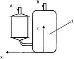
图1为本发明的空调压缩机故障诊断系统的测试示意图;Fig. 1 is the test schematic diagram of the fault diagnosis system of the air-conditioning compressor of the present invention;
图2为本发明的空调压缩机故障诊断系统的结构示意图;Fig. 2 is the structural schematic diagram of the fault diagnosis system of the air-conditioning compressor of the present invention;
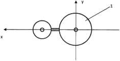
图3为本发明的空调压缩机故障诊断系统中传感器布置点的示意图;3 is a schematic diagram of sensor arrangement points in the air-conditioning compressor fault diagnosis system of the present invention;
图4为图3的俯视图;Fig. 4 is the top view of Fig. 3;
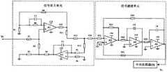
图5为本发明的信号处理电路的电路图。FIG. 5 is a circuit diagram of a signal processing circuit of the present invention.
附图标记:Reference number:
1-压缩机;2-排气管;3-排气管防振软管;4-吸气管;5-吸气管防振软管;6-四通阀;7-蒸发器;8-冷凝器;9-中央处理器;10-振动监测模块;11-信号处理电路;12-无线传输模块;13-显示模块;14-存储模块;15-数据分析模块;A和B为振动传感器布置点。1-compressor; 2-exhaust pipe; 3-exhaust pipe anti-vibration hose; 4-suction pipe; 5-suction pipe anti-vibration hose; 6-four-way valve; 7-evaporator; 8- Condenser; 9-CPU; 10-Vibration monitoring module; 11-Signal processing circuit; 12-Wireless transmission module; 13-Display module; 14-Storage module; 15-Data analysis module; A and B are arranged for vibration sensor point.
具体实施方式Detailed ways
下面结合附图和实施例对本发明提供的空调压缩机故障诊断系统进行详细说明。The air conditioner compressor fault diagnosis system provided by the present invention will be described in detail below with reference to the accompanying drawings and embodiments.
如图1-2所示,本发明提供的空调压缩机故障诊断系统包括压缩机1、排气管2、排气管防振软管3、吸气管4、吸气管防振软管5、四通阀6、蒸发器7、冷凝器8、中央处理器9、振动监测模块10、信号处理电路11、无线传输模块12、显示模块13、存储模块14以及数据分析模块15。As shown in Figures 1-2, the fault diagnosis system for an air conditioner compressor provided by the present invention includes a
其中,压缩机1的排气管口通过排气管2与四通阀6连接,压缩机1的吸气管口通过吸气管4与四通阀6连接,排气管防振软管3套设于排气管2上,吸气管防振软管5套设于吸气管4上,四通阀6与蒸发器7连接,四通阀6还与冷凝器8连接,蒸发器7与冷凝器8连接,振动监测模块10包括若干个设置于压缩机1的排气管口和吸气管口处的振动传感器,振动传感器与信号处理电路11的输入端连接,信号处理电路11的输出端与中央处理器9的输入端连接,显示模块13的输入端与存储模块14的输入端均与中央处理器9的输出端连接,中央处理器9的输出端与无线传输模块12的输入端连接,数据分析模块15与无线传输模块12双向通讯连接,无线传输模块12的输出端还与显示模块13的输入端连接。Among them, the exhaust pipe port of the
如图3-4所示,振动传感器设置于压缩机1的吸气管口和排气管口处的x、y、z三个方向。As shown in Figure 3-4, the vibration sensors are arranged in the three directions of x, y, and z at the inlet and outlet of the
上述实施方式中,由于压缩机1的振动存在于多个方向,因此在同一测量点需测试多个方向的振动值,因此以压缩机1吸、排气管口连线设为x方向,以水平面内垂直于吸、排气管口连线方向设为y方向,以垂直于水平面的竖直方向设为z方向,分别在吸、排气管口上的测量点A、B处沿x、y、z三个方向布置相应的振动传感器,然后接通电源,待工况稳定后可测试压缩机1在启动、运行及停机状态下的振动数据。In the above embodiment, since the vibration of the
所述排气管隔振软管3和吸气管隔振软管5均为两头带有活螺母的快速管接头,避免了压缩机1与吸排气管路系统之间振动的传递,且避免了吸排气管路的振动对压缩机1的影响,使测试结果更为准确。The exhaust pipe
所述排气管2和吸气管4的一端与蒸发器7和冷凝器8之间设有四通阀6。A four-
通过四通阀6可以精准地控制吸排气管与蒸发器7和冷凝器8之间的气液流通,从而根据需求实现制热或制冷。The gas-liquid flow between the suction and exhaust pipes, the evaporator 7 and the condenser 8 can be precisely controlled by the four-
上述实施方式中,压缩机1的吸排气管口分别通过隔振软管与吸气管和排气管相连,用于隔离压缩机与管路的振动传递,避免了吸气管和排气管自身的固有频率和压缩机的振动形成共振,在测量压缩机振动情况时,降低外界干扰,提高测量精度。In the above embodiment, the suction and exhaust pipe ports of the
如图5所示,振动传感器用于检测空调压缩机吸气管口和排气管口的振动信号,将采集的振动信号转换为电压信号V0,并将电压信号V0传输至信号处理电路11,V1为经过信号处理电路11处理后的电压信号,信号处理电路11包括信号放大单元和信号滤波单元,振动传感器的输出端与信号放大单元的输入端连接,信号放大单元的输出端与信号滤波单元的输入端连接,信号滤波单元的输出端与中央处理器9的ADC端口连接。As shown in FIG. 5 , the vibration sensor is used to detect the vibration signal of the air-conditioning compressor suction nozzle and exhaust nozzle, convert the collected vibration signal into a voltage signal V0, and transmit the voltage signal V0 to the signal processing circuit 11, V1 is the voltage signal processed by the signal processing circuit 11. The signal processing circuit 11 includes a signal amplifying unit and a signal filtering unit. The output end of the vibration sensor is connected to the input end of the signal amplifying unit, and the output end of the signal amplifying unit is connected to the signal filtering unit. The input end of the signal filtering unit is connected to the ADC port of the central processing unit 9 .
具体地,信号放大单元包括集成运放A1-A2、电阻R1-R14以及电容C1-C2。Specifically, the signal amplification unit includes integrated operational amplifiers A1-A2, resistors R1-R14 and capacitors C1-C2.
其中,振动传感器的输出端与电阻R1的一端连接,电阻R3的一端接地,电阻R3的另一端与电阻R2的一端连接,电阻R1的另一端与电阻R2的另一端连接,电阻R1的另一端还与集成运放A1的同相输入端连接,电阻R3的另一端还与电阻R4的一端连接,电阻R4的另一端与集成运放A2的输出端连接,电阻R5的一端与集成运放A2的反相输入端连接,电阻R4的另一端还与电容C2的一端连接,电容C2的另一端与电阻R5的一端连接,电阻R6的一端与集成运放A2的同相输入端连接,电阻R6的另一端接地,电阻R7的一端接地,电阻R7的另一端与电阻R8的一端连接,电阻R8的另一端与集成运放A1的反相输入端连接,电阻R8的一端还与电容C1的一端连接,电阻R8的另-端还与电容C1的另一端连接,电阻R7的另一端还与电阻R9的一端连接,电阻R10的一端与集成运放A1的输出端连接,电阻R10的另一端与电阻R9的另一端连接,电阻R11的一端与电阻R12的一端连接,电阻R11的另一端与电阻R10的另一端连接,电阻R12的另一端与电阻R14的一端连接,电阻R5的另一端与电阻R13的一端连接,电阻R13的另一端与电阻R14的一端连接,电阻R14的另一端与信号滤波单元的输入端连接。The output end of the vibration sensor is connected to one end of the resistor R1, one end of the resistor R3 is grounded, the other end of the resistor R3 is connected to one end of the resistor R2, the other end of the resistor R1 is connected to the other end of the resistor R2, and the other end of the resistor R1 is connected It is also connected to the non-inverting input terminal of the integrated operational amplifier A1, the other end of the resistor R3 is also connected to one end of the resistor R4, the other end of the resistor R4 is connected to the output terminal of the integrated operational amplifier A2, and one end of the resistor R5 is connected to the integrated operational amplifier A2. The inverting input is connected, the other end of the resistor R4 is also connected to one end of the capacitor C2, the other end of the capacitor C2 is connected to one end of the resistor R5, the other end of the resistor R6 is connected to the non-inverting input of the integrated operational amplifier A2, and the other end of the resistor R6 is connected. One end is grounded, one end of resistor R7 is grounded, the other end of resistor R7 is connected to one end of resistor R8, the other end of resistor R8 is connected to the inverting input end of integrated operational amplifier A1, and one end of resistor R8 is also connected to one end of capacitor C1, The other end of the resistor R8 is also connected to the other end of the capacitor C1, the other end of the resistor R7 is also connected to one end of the resistor R9, one end of the resistor R10 is connected to the output end of the integrated operational amplifier A1, and the other end of the resistor R10 is connected to the resistor R9. The other end of resistor R11 is connected to one end of resistor R12, the other end of resistor R11 is connected to the other end of resistor R10, the other end of resistor R12 is connected to one end of resistor R14, the other end of resistor R5 is connected to the other end of resistor R13 One end is connected, the other end of the resistor R13 is connected to one end of the resistor R14, and the other end of the resistor R14 is connected to the input end of the signal filtering unit.
具体地,信号滤波单元包括电阻R15-R21、电容C3-C4以及集成运放A3-A5。Specifically, the signal filtering unit includes resistors R15-R21, capacitors C3-C4 and integrated operational amplifiers A3-A5.
其中,信号放大单元的输出端与电阻R15的一端连接,电阻R15的另一端与电阻R17的一端并联后与集成运放A3的同相输入端连接,电阻R17的另一端与集成运放A3的输出端连接,电阻R16的一端接地,电阻R16的另一端与电阻R21并联后与集成运放A3的同相输入端连接,电阻R21的另一端与集成运放A3的输出端连接,电阻R17的另一端与集成运放A3的输出端并联后与电阻R18的一端连接,电阻R18的另一端与电容C8的一端并联后与集成运放A4的反相输入端连接,电容C8的另一端与集成运放A4的输出端并联后与电阻R19的一端连接,集成运放A4的同相输入端接地,电阻R19的另一端与电容C9的一端并联后与集成运放A5的反相输入端连接,集成运放A5的同相输入端接地,电容C9的另一端与集成运放A5的输出端连接,电阻R20的一端与集成运放A3的反相输入端连接,电阻R20的另一端与集成运放A5的输出端连接,电阻R21的一端与集成运放A3的同相输入端连接,电阻R21的另一端与集成运放A4的输出端连接,集成运放A5的输出端与中央处理器9的ADC端口连接,信号处理单元将处理后的电压信号V1传输至中央处理器9的ADC端口。Among them, the output end of the signal amplification unit is connected to one end of the resistor R15, the other end of the resistor R15 is connected in parallel with one end of the resistor R17 and then connected to the non-inverting input end of the integrated operational amplifier A3, and the other end of the resistor R17 is connected to the output of the integrated operational amplifier A3 The other end of the resistor R16 is connected to the non-inverting input end of the integrated operational amplifier A3 after being connected in parallel with the resistor R21, the other end of the resistor R21 is connected to the output end of the integrated operational amplifier A3, and the other end of the resistor R17 is connected to the ground. It is connected in parallel with the output end of the integrated operational amplifier A3 and then connected to one end of the resistor R18. The other end of the resistor R18 is connected in parallel with one end of the capacitor C8 and then connected to the inverting input end of the integrated operational amplifier A4. The other end of the capacitor C8 is connected to the integrated operational amplifier. The output end of A4 is connected in parallel with one end of the resistor R19, the non-inverting input end of the integrated operational amplifier A4 is grounded, the other end of the resistor R19 is connected in parallel with one end of the capacitor C9 and then connected to the inverting input end of the integrated operational amplifier A5, the integrated operational amplifier The non-inverting input of A5 is grounded, the other end of capacitor C9 is connected to the output of integrated operational amplifier A5, one end of resistor R20 is connected to the inverting input of integrated operational amplifier A3, and the other end of resistor R20 is connected to the output of integrated operational amplifier A5 One end of the resistor R21 is connected to the non-inverting input end of the integrated operational amplifier A3, the other end of the resistor R21 is connected to the output end of the integrated operational amplifier A4, and the output end of the integrated operational amplifier A5 is connected to the ADC port of the central processing unit 9. The signal processing unit transmits the processed voltage signal V1 to the ADC port of the central processing unit 9 .
上述实施方式中,信号处理电路11的噪声在50nV以内,漂移为0.4μV/℃,集成运放A1为LT1113低漂移放大器,集成运放A2为LT1230高速放大器,集成运放A3、A4和A5均为LT1097运放,由于集成运放A1的直流偏移与漂移并不会影响电路的整体偏移,从而使得电路有着极低的偏移和漂移。In the above-mentioned embodiment, the noise of the signal processing circuit 11 is within 50nV, and the drift is 0.4μV/°C. For the LT1097 op amp, since the DC offset and drift of the integrated op amp A1 will not affect the overall offset of the circuit, the circuit has extremely low offset and drift.
电阻R1的阻值为1KΩ,电阻R2的阻值为100MΩ,电阻R3的阻值为1MΩ,电阻R4的阻值为100KΩ,电阻R5的阻值为1MΩ,R6的阻值为1MΩ,电阻R7的阻值为200Ω,电阻R8的阻值为100MΩ,电阻R9的阻值为3.9KΩ,电阻R10的阻值为100KΩ,电阻R11的阻值为1KΩ,电阻R12的阻值为100KΩ,电阻R13的阻值为1KΩ,电阻R14的阻值为5.1KΩ,电阻R15的阻值为1.7KΩ,电阻R16的阻值为4.7KΩ,电阻R17的阻值为10KΩ,电阻R18的阻值为5KΩ,电阻R19的阻值为1KΩ,电阻R20的阻值为5KΩ,电阻R21的阻值为5KΩ,容C1的电容值为50pF,电容C2的电容值为1μF,C3的电容值为390pF,电容C4的电容值为470pF。The resistance value of resistor R1 is 1KΩ, the resistance value of resistor R2 is 100MΩ, the resistance value of resistor R3 is 1MΩ, the resistance value of resistor R4 is 100KΩ, the resistance value of resistor R5 is 1MΩ, the resistance value of resistor R6 is 1MΩ, and the resistance value of resistor R7 is 1MΩ. The resistance value is 200Ω, the resistance value of the resistor R8 is 100MΩ, the resistance value of the resistor R9 is 3.9KΩ, the resistance value of the resistor R10 is 100KΩ, the resistance value of the resistor R11 is 1KΩ, the resistance value of the resistor R12 is 100KΩ, and the resistance value of the resistor R13 is 100KΩ. The resistance value is 1KΩ, the resistance value of the resistor R14 is 5.1KΩ, the resistance value of the resistor R15 is 1.7KΩ, the resistance value of the resistor R16 is 4.7KΩ, the resistance value of the resistor R17 is 10KΩ, the resistance value of the resistor R18 is 5KΩ, and the resistance value of the resistor R19 is 5KΩ. The resistance value is 1KΩ, the resistance value of resistor R20 is 5KΩ, the resistance value of resistor R21 is 5KΩ, the capacitance value of capacitor C1 is 50pF, the capacitance value of capacitor C2 is 1μF, the capacitance value of C3 is 390pF, and the capacitance value of capacitor C4 is 470pF.
由于振动传感器采集的信号为微弱的电压信号,因而信号放大单元通过电阻R1-R14、电容C1-C2以及集成运放A1-A2对振动传感器输出的电压V0进行放大处理,由电阻R1-R14、电容C1-C2以及集成运放A1-A2构成的信号放大单元只有0.5μV/℃的漂移、5μV以内的偏移、100pA偏置电流和0.1Hz到10Hz宽带内50nV的噪声。其中,信号滤波单元使用电阻R15-R21,电容C3-C4以及集成运放A3-A5对经过放大后的电压信号进行低通滤波处理,从而提高了振动检测的精度。Since the signal collected by the vibration sensor is a weak voltage signal, the signal amplification unit amplifies the voltage V0 output by the vibration sensor through resistors R1-R14, capacitors C1-C2 and integrated operational amplifiers A1-A2. The signal amplifying unit composed of capacitors C1-C2 and integrated operational amplifiers A1-A2 has only 0.5μV/℃ drift, offset within 5μV, 100pA bias current and 50nV noise within 0.1Hz to 10Hz wideband. Among them, the signal filtering unit uses resistors R15-R21, capacitors C3-C4 and integrated operational amplifiers A3-A5 to perform low-pass filtering on the amplified voltage signal, thereby improving the accuracy of vibration detection.
具体地,三个振动传感器分别设置于压缩机1的吸气管口处的x、y、z三个方向,三个传感器将测得的振动信号经过信号处理电路11依次进行信号放大和滤波处理后测得压缩机1的吸气管口处的x、y、z三个方向的振动值分别为A1、A2和A3,三个振动传感器分别设置于压缩机1的排气管口处的x、y、z三个方向,三个传感器将测得的振动信号经过信号处理电路11依次进行信号放大和滤波处理后测得压缩机1的排气管口处的x、y、z三个方向的振动值分别为B1、B2和B3,中央处理器9将接收到的振动值A1、A2、A3、B1、B2和B3传输至显示模块13进行显示,中央处理器9将接收到的振动值A1、A2、A3、B1、B2和B3传输至存储模块14进行存储,中央处理器9将接收到的振动值A1、A2、A3、B1、B2和B3通过无线传输模块12传输至数据分析模块15。Specifically, the three vibration sensors are respectively arranged in the three directions of x, y, and z at the suction nozzle of the
具体地,数据分析模块15根据接收到的振动值A1、A2、A3、B1、B2和B3分析得压缩机1x方向的振动值C1=A1+B1、y方向的振动值C2=A2+B2、z方向的振动值C3=A3+B3,数据分析模块15将振动值C1与预设x方向振动阈值进行比较、振动值C2与预设y方向振动阈值进行比较以及振动值C3与预设z方向振动阈值进行比较,并将比较结果通过无线传输模块12传输至显示模块13进行显示。Specifically, the data analysis module 15 analyzes the received vibration values A1, A2, A3, B1, B2 and B3 to obtain the vibration value C1=A1+B1 of the compressor 1x direction, the vibration value C2=A2+B2 of the y direction, The vibration value C3=A3+B3 in the z direction, the data analysis module 15 compares the vibration value C1 with the preset x-direction vibration threshold, the vibration value C2 compares with the preset y-direction vibration threshold, and the vibration value C3 and the preset z-direction The vibration thresholds are compared, and the comparison result is transmitted to the display module 13 through the wireless transmission module 12 for display.
若振动值C1大于预设x方向振动阈值,则数据分析模块15将压缩机1的x方向振动过大的报警信息通过无线传输模块12传输至显示模块13进行显示。If the vibration value C1 is greater than the preset x-direction vibration threshold, the data analysis module 15 transmits the alarm information of excessive vibration of the
若振动值C2大于预设y方向振动阈值,则数据分析模块15将压缩机1的y方向振动过大的报警信息通过无线传输模块12传输至显示模块13进行显示。If the vibration value C2 is greater than the preset y-direction vibration threshold, the data analysis module 15 transmits the alarm information of excessive vibration in the y-direction of the
若振动值C3大于预设z方向振动阈值,则数据分析模块15将压缩机1的z方向振动过大的报警信息通过无线传输模块12传输至显示模块13进行显示。If the vibration value C3 is greater than the preset z-direction vibration threshold, the data analysis module 15 transmits the alarm information of excessive z-direction vibration of the
具体地,数据分析模块15根据接收到的振动值A1、A2、A3、B1、B2和B3分析得压缩机1吸气管口处的振动值D1为:Specifically, the data analysis module 15 analyzes the vibration value D1 at the suction nozzle of the

分析得压缩机1排气管口处的振动值D2为:According to the analysis, the vibration value D2 at the outlet of the

数据分析模块15将振动值D1与预设吸气管口处的振动阈值进行比较和振动值D2与预设排气管口处的振动阈值进行比较,并将比较结果通过无线传输模块12传输至显示模块13进行显示。The data analysis module 15 compares the vibration value D1 with the vibration threshold at the preset suction nozzle, and compares the vibration value D2 with the vibration threshold at the preset exhaust nozzle, and transmits the comparison result to the wireless transmission module 12. The display module 13 displays.
若振动值D1大于预设吸气管口处的振动阈值,则数据分析模块15将压缩机1的吸气管口处的振动过大的报警信息通过无线传输模块12传输至显示模块13进行显示。If the vibration value D1 is greater than the preset vibration threshold at the suction nozzle, the data analysis module 15 transmits the alarm information of excessive vibration at the suction nozzle of the
若振动值D2大于预设排气管口处的振动阈值,则数据分析模块15将压缩机1的排气管口处的振动过大的报警信息通过无线传输模块12传输至显示模块13进行显示。If the vibration value D2 is greater than the preset vibration threshold value at the outlet of the exhaust pipe, the data analysis module 15 transmits the alarm information of excessive vibration at the outlet of the
具体地,振动传感器为加速度传感器。Specifically, the vibration sensor is an acceleration sensor.
具体地,排气管防振软管3和吸气管防振软管5为两头带有活螺母的快速管接头。Specifically, the
本发明提供的空调压缩机故障诊断系统,利用压缩机、排气管、排气管防振软管、吸气管、吸气管防振软管、四通阀、蒸发器、冷凝器、中央处理器、振动监测模块、信号处理电路、无线传输模块、显示模块、存储模块以及数据分析模块对空调压缩机的振动信号进行监测,振动传感器设置于压缩机的吸气管口和排气管口处的x、y、z三个方向,并通过数据分析模块计算压缩机x方向的振动值、y方向的振动值、z方向的振动值、压缩机吸气管口处的振动值以及压缩机排气管口处的振动值,并将计算得到的上述振动值分别与数据分析模块内的预设阈值进行比较,以对空调压缩机故障进行诊断。The air conditioner compressor fault diagnosis system provided by the present invention utilizes the compressor, the exhaust pipe, the exhaust pipe anti-vibration hose, the suction pipe, the suction pipe anti-vibration hose, the four-way valve, the evaporator, the condenser, the central The processor, the vibration monitoring module, the signal processing circuit, the wireless transmission module, the display module, the storage module and the data analysis module monitor the vibration signal of the air-conditioning compressor, and the vibration sensor is arranged at the suction pipe port and the exhaust pipe port of the compressor The three directions of x, y, and z are calculated by the data analysis module, and the vibration value of the compressor in the x direction, the vibration value in the y direction, the vibration value in the z direction, the vibration value at the compressor suction nozzle and the compressor vibration value are calculated by the data analysis module. The vibration value at the outlet of the exhaust pipe is compared, and the calculated vibration value is compared with the preset threshold value in the data analysis module, so as to diagnose the fault of the air conditioner compressor.
最后所应说明的是,以上实施例仅用以说明本发明的技术方案而非限制。尽管参照实施例对本发明进行了详细说明,本领域的普通技术人员应当理解,对本发明的技术方案进行修改或者等同替换,都不脱离本发明技术方案的精神和范围,其均应涵盖在本发明的权利要求范围当中。Finally, it should be noted that the above embodiments are only used to illustrate the technical solutions of the present invention and not to limit them. Although the present invention has been described in detail with reference to the embodiments, those of ordinary skill in the art should understand that any modification or equivalent replacement of the technical solutions of the present invention will not depart from the spirit and scope of the technical solutions of the present invention, and should be included in the present invention. within the scope of the claims.
Claims (10)
Translated fromChinese

Priority Applications (1)
| Application Number | Priority Date | Filing Date | Title |
|---|---|---|---|
| CN201811513951.3ACN111237182A (en) | 2018-11-29 | 2018-11-29 | A fault diagnosis system for an air conditioner compressor |
Applications Claiming Priority (1)
| Application Number | Priority Date | Filing Date | Title |
|---|---|---|---|
| CN201811513951.3ACN111237182A (en) | 2018-11-29 | 2018-11-29 | A fault diagnosis system for an air conditioner compressor |
Publications (1)
| Publication Number | Publication Date |
|---|---|
| CN111237182Atrue CN111237182A (en) | 2020-06-05 |
Family
ID=70874014
Family Applications (1)
| Application Number | Title | Priority Date | Filing Date |
|---|---|---|---|
| CN201811513951.3APendingCN111237182A (en) | 2018-11-29 | 2018-11-29 | A fault diagnosis system for an air conditioner compressor |
Country Status (1)
| Country | Link |
|---|---|
| CN (1) | CN111237182A (en) |
Cited By (3)
| Publication number | Priority date | Publication date | Assignee | Title |
|---|---|---|---|---|
| CN113565748A (en)* | 2021-09-23 | 2021-10-29 | 苏州卓樱自动化设备有限公司 | Performance test equipment and method for compressor |
| CN114252219A (en)* | 2021-11-15 | 2022-03-29 | 青岛海尔空调器有限总公司 | Pipeline detection device and air conditioner pipeline detection method |
| CN119532892A (en)* | 2024-12-19 | 2025-02-28 | Tcl空调器(中山)有限公司 | Air conditioner and fault detection method, device and computer readable storage medium thereof |
Citations (7)
| Publication number | Priority date | Publication date | Assignee | Title |
|---|---|---|---|---|
| EP2220372A1 (en)* | 2007-11-02 | 2010-08-25 | Emerson Climate Technologies, Inc. | Compressor sensor module |
| CN203476683U (en)* | 2013-07-05 | 2014-03-12 | 安庆市佰联无油压缩机有限公司 | Laboratory monitoring system for running state of compressor |
| CN105241026A (en)* | 2015-10-30 | 2016-01-13 | 海信(山东)空调有限公司 | Vibration controlling method and device |
| CN205038312U (en)* | 2015-10-22 | 2016-02-17 | 傅乃超 | Power electronic fault diagnosis device |
| CN108645477A (en)* | 2018-08-27 | 2018-10-12 | 南京梵科智能科技有限公司 | A kind of reservoir level intelligent monitor system |
| CN207960910U (en)* | 2018-03-23 | 2018-10-12 | 四川长虹空调有限公司 | Cooler compressor vibration test system |
| WO2018198221A1 (en)* | 2017-04-26 | 2018-11-01 | 三菱電機株式会社 | Deterioration diagnosis device and air conditioning device |
- 2018
- 2018-11-29CNCN201811513951.3Apatent/CN111237182A/enactivePending
Patent Citations (7)
| Publication number | Priority date | Publication date | Assignee | Title |
|---|---|---|---|---|
| EP2220372A1 (en)* | 2007-11-02 | 2010-08-25 | Emerson Climate Technologies, Inc. | Compressor sensor module |
| CN203476683U (en)* | 2013-07-05 | 2014-03-12 | 安庆市佰联无油压缩机有限公司 | Laboratory monitoring system for running state of compressor |
| CN205038312U (en)* | 2015-10-22 | 2016-02-17 | 傅乃超 | Power electronic fault diagnosis device |
| CN105241026A (en)* | 2015-10-30 | 2016-01-13 | 海信(山东)空调有限公司 | Vibration controlling method and device |
| WO2018198221A1 (en)* | 2017-04-26 | 2018-11-01 | 三菱電機株式会社 | Deterioration diagnosis device and air conditioning device |
| CN207960910U (en)* | 2018-03-23 | 2018-10-12 | 四川长虹空调有限公司 | Cooler compressor vibration test system |
| CN108645477A (en)* | 2018-08-27 | 2018-10-12 | 南京梵科智能科技有限公司 | A kind of reservoir level intelligent monitor system |
Cited By (4)
| Publication number | Priority date | Publication date | Assignee | Title |
|---|---|---|---|---|
| CN113565748A (en)* | 2021-09-23 | 2021-10-29 | 苏州卓樱自动化设备有限公司 | Performance test equipment and method for compressor |
| CN114252219A (en)* | 2021-11-15 | 2022-03-29 | 青岛海尔空调器有限总公司 | Pipeline detection device and air conditioner pipeline detection method |
| WO2023082621A1 (en)* | 2021-11-15 | 2023-05-19 | 青岛海尔空调器有限总公司 | Pipeline detection apparatus and air conditioner pipeline detection method |
| CN119532892A (en)* | 2024-12-19 | 2025-02-28 | Tcl空调器(中山)有限公司 | Air conditioner and fault detection method, device and computer readable storage medium thereof |
Similar Documents
| Publication | Publication Date | Title |
|---|---|---|
| CN111237182A (en) | A fault diagnosis system for an air conditioner compressor | |
| CN111964848A (en) | Small pressure container trace gas leakage emergency ultrasonic detection system and method | |
| CN205607957U (en) | Centralized conflagration characteristic gas detection device | |
| CN107167223A (en) | Transducer air conditioning compressor and pipeline vibration test system and method | |
| CN205510002U (en) | Amplification and filtering circuit of special signal of telecommunication | |
| CN112305329B (en) | Device and method for component state detection based on low frequency noise | |
| CN104360178B (en) | A kind of inverter low-frequency noise measurement and method for diagnosing faults | |
| KR20180000372A (en) | Diagnostic apparatus and diagnostic method for compressed air | |
| CN207215480U (en) | A kind of performance detection device for automobile air conditioner | |
| CN104730284B (en) | Sampling wind speed monitoring device and enthalpy difference method experiment detection equipment with same | |
| CN214121502U (en) | Corrosion leakage detection system | |
| CN108375415A (en) | Transmission line of electricity aero-vibration monitoring device calibration method under a kind of site environment | |
| CN108303267B (en) | Integrated vehicle air conditioning unit testing device | |
| KR102568086B1 (en) | Apparatus and Method for Detecting Leak of Pipe | |
| CN104132251B (en) | Method and device for multi-directional collection of acoustic vibration signals of pressure fluid pipeline | |
| CN106323843A (en) | Fault detection method and fault detector for cloth bag of dust remover | |
| CN206920008U (en) | Transducer air conditioning compressor and pipeline vibration test system | |
| CN207960910U (en) | Cooler compressor vibration test system | |
| CN212155114U (en) | Intelligent Air Compressor Performance Testing System and Air Compressor Flow Testing Device | |
| CN204514468U (en) | A kind of refrigerator vibration detection device | |
| CN101413848A (en) | Wireless remote control type smoke / gas tester | |
| CN205404065U (en) | Non -destructive inspection dynamic testing system | |
| CN206321545U (en) | Dust-collecting bag fault locator | |
| CN220419446U (en) | Resistance detection device | |
| CN221926037U (en) | A particle detection structure for clean room |
Legal Events
| Date | Code | Title | Description |
|---|---|---|---|
| PB01 | Publication | ||
| PB01 | Publication | ||
| SE01 | Entry into force of request for substantive examination | ||
| SE01 | Entry into force of request for substantive examination | ||
| RJ01 | Rejection of invention patent application after publication | Application publication date:20200605 | |
| RJ01 | Rejection of invention patent application after publication |