CN111230594A - On-line machining deformation detection device and compensation method of CNC machining center - Google Patents
On-line machining deformation detection device and compensation method of CNC machining centerDownload PDFInfo
- Publication number
- CN111230594A CN111230594ACN202010097988.3ACN202010097988ACN111230594ACN 111230594 ACN111230594 ACN 111230594ACN 202010097988 ACN202010097988 ACN 202010097988ACN 111230594 ACN111230594 ACN 111230594A
- Authority
- CN
- China
- Prior art keywords
- machining center
- deformation
- machining
- angle adjuster
- measurement
- Prior art date
- Legal status (The legal status is an assumption and is not a legal conclusion. Google has not performed a legal analysis and makes no representation as to the accuracy of the status listed.)
- Pending
Links
Images


Classifications
- B—PERFORMING OPERATIONS; TRANSPORTING
- B23—MACHINE TOOLS; METAL-WORKING NOT OTHERWISE PROVIDED FOR
- B23Q—DETAILS, COMPONENTS, OR ACCESSORIES FOR MACHINE TOOLS, e.g. ARRANGEMENTS FOR COPYING OR CONTROLLING; MACHINE TOOLS IN GENERAL CHARACTERISED BY THE CONSTRUCTION OF PARTICULAR DETAILS OR COMPONENTS; COMBINATIONS OR ASSOCIATIONS OF METAL-WORKING MACHINES, NOT DIRECTED TO A PARTICULAR RESULT
- B23Q17/00—Arrangements for observing, indicating or measuring on machine tools
- B23Q17/20—Arrangements for observing, indicating or measuring on machine tools for indicating or measuring workpiece characteristics, e.g. contour, dimension, hardness
- B—PERFORMING OPERATIONS; TRANSPORTING
- B23—MACHINE TOOLS; METAL-WORKING NOT OTHERWISE PROVIDED FOR
- B23Q—DETAILS, COMPONENTS, OR ACCESSORIES FOR MACHINE TOOLS, e.g. ARRANGEMENTS FOR COPYING OR CONTROLLING; MACHINE TOOLS IN GENERAL CHARACTERISED BY THE CONSTRUCTION OF PARTICULAR DETAILS OR COMPONENTS; COMBINATIONS OR ASSOCIATIONS OF METAL-WORKING MACHINES, NOT DIRECTED TO A PARTICULAR RESULT
- B23Q15/00—Automatic control or regulation of feed movement, cutting velocity or position of tool or work
- B23Q15/007—Automatic control or regulation of feed movement, cutting velocity or position of tool or work while the tool acts upon the workpiece
- B23Q15/12—Adaptive control, i.e. adjusting itself to have a performance which is optimum according to a preassigned criterion
- B—PERFORMING OPERATIONS; TRANSPORTING
- B23—MACHINE TOOLS; METAL-WORKING NOT OTHERWISE PROVIDED FOR
- B23Q—DETAILS, COMPONENTS, OR ACCESSORIES FOR MACHINE TOOLS, e.g. ARRANGEMENTS FOR COPYING OR CONTROLLING; MACHINE TOOLS IN GENERAL CHARACTERISED BY THE CONSTRUCTION OF PARTICULAR DETAILS OR COMPONENTS; COMBINATIONS OR ASSOCIATIONS OF METAL-WORKING MACHINES, NOT DIRECTED TO A PARTICULAR RESULT
- B23Q17/00—Arrangements for observing, indicating or measuring on machine tools
- B23Q17/24—Arrangements for observing, indicating or measuring on machine tools using optics or electromagnetic waves
- B23Q17/2452—Arrangements for observing, indicating or measuring on machine tools using optics or electromagnetic waves for measuring features or for detecting a condition of machine parts, tools or workpieces
- B23Q17/2471—Arrangements for observing, indicating or measuring on machine tools using optics or electromagnetic waves for measuring features or for detecting a condition of machine parts, tools or workpieces of workpieces
Landscapes
- Engineering & Computer Science (AREA)
- Mechanical Engineering (AREA)
- Physics & Mathematics (AREA)
- Optics & Photonics (AREA)
- Numerical Control (AREA)
- Machine Tool Sensing Apparatuses (AREA)
Abstract
Translated fromChinese
Description
Translated fromChinese技术领域technical field
本发明属于精密机械加工技术领域,特别是涉及到一种数控加工中心在线加工变形检测、补偿方法及检测装置。The invention belongs to the technical field of precision machining, and in particular relates to a deformation detection and compensation method and a detection device for on-line machining of a numerical control machining center.
背景技术Background technique
随着航空航天、国防工业、微电子工业、宇宙开发、海洋技术、汽车制造等高科技领域的飞速发展,材料的轻、软特性现在也越来越普及到零件上来。传统在线接触测量方法会使零件表面受力导致表面出现凹坑,尤其是极易变形或者弱刚度零件,更加无法进接触式测量,我们就需要打破常规的理念来实现在线测量,以便减少装夹及在线补偿,这样就会大大提高零件加工精度减小表面破坏。因此,寻找一套有效的测量方法和装置迫在眉睫。With the rapid development of aerospace, defense industry, microelectronics industry, space development, marine technology, automobile manufacturing and other high-tech fields, the light and soft characteristics of materials are now more and more popular in parts. The traditional online contact measurement method will cause the surface of the part to be stressed and cause pits on the surface, especially the easily deformed or weakly rigid parts, and it is even more impossible to perform contact measurement. We need to break the conventional concept to achieve online measurement in order to reduce clamping. And online compensation, which will greatly improve the machining accuracy of parts and reduce surface damage. Therefore, it is urgent to find a set of effective measurement methods and devices.
发明内容SUMMARY OF THE INVENTION
本发明所要解决的技术问题是:提供一种数控加工中心在线加工变形检测装置及补偿方法,采取多点、定点检测,测量前进行测量装置数据标定,可提高测量数据准确性,便于加工误差补偿。The technical problem to be solved by the present invention is: to provide an online machining deformation detection device and compensation method for a numerical control machining center, adopting multi-point and fixed-point detection, and performing data calibration of the measurement device before measurement, which can improve the accuracy of measurement data and facilitate machining error compensation .
数控加工中心在线加工变形检测装置,其特征是:包括数控加工中心刀柄、角度调节器、角度调节手柄、激光发射接收器、激光发射口、激光信号接收口以及信号输出接线口,所述数控加工中心刀柄与角度调节器连接,所述角度调节器的外部设置有角度调节手柄,角度调节器的一端设置有凹槽;所述激光发射接收器与角度调节手柄连接,设置在角度调节器的凹槽内部,激光发射接收器端面设置有激光发射口和激光信号接收口,侧面设置有信号输出接线口。The on-line machining deformation detection device of a CNC machining center is characterized in that it includes a tool handle of a CNC machining center, an angle adjuster, an angle adjustment handle, a laser emission receiver, a laser emission port, a laser signal receiving port and a signal output wiring port. The tool handle of the machining center is connected with the angle adjuster, the outside of the angle adjuster is provided with an angle adjuster handle, and one end of the angle adjuster is provided with a groove; the laser transmitter receiver is connected with the angle adjuster handle and is disposed on the angle adjuster Inside the groove of the laser transmitter, the end face of the laser transmitter receiver is provided with a laser transmitter port and a laser signal receiver port, and the side is provided with a signal output connection port.
数控加工中心在线加工变形检测及补偿方法,其特征是:包括以下步骤,且以下步骤顺次进行,A method for detecting and compensating for on-line machining deformation of a numerically controlled machining center is characterized in that: it comprises the following steps, and the following steps are performed in sequence,
步骤一、首先根据零件图纸尺寸标注,建立三维模型;
步骤二:进行数控加工中心在线加工变形检测装置校准;Step 2: Carry out the calibration of the online machining deformation detection device of the CNC machining center;
步骤三:根据步骤一图纸中要测量的尺寸部分来调节角度调节器,使其激光光路垂直于检测表面;Step 3: Adjust the angle adjuster according to the dimension to be measured in the drawing in
步骤四:利用步骤一建立的三维模型来编写测量路径程序;Step 4: Use the 3D model established in
步骤五:利用步骤四编写的程序点位路径进行测量点数据提取;Step 5: Use the program point path written in
步骤六:计算测量点坐标差值用于确定各工件坐标位置变形量;Step 6: Calculate the coordinate difference of the measuring point to determine the deformation of each workpiece coordinate position;
步骤七:步骤六获得的变形量与原模型数据对比进行误差补偿;Step 7: Comparing the deformation amount obtained in
步骤八:利用补偿量精加工外轮廓结构。Step 8: Use the compensation amount to finish the outer contour structure.
所述步骤二中采用校准块进行数控加工中心在线加工变形检测装置校准,校准块的尺寸及型面精度为0.001mm。In the second step, a calibration block is used to calibrate the online machining deformation detection device of the CNC machining center, and the size and profile accuracy of the calibration block are 0.001 mm.
所述步骤三中采用的角度调节器装配面精度为0.001mm,旋转角精度为1″,光路与被测工件表面垂直度为0.001mm。The precision of the assembly surface of the angle adjuster used in the third step is 0.001mm, the precision of the rotation angle is 1″, and the perpendicularity between the optical path and the surface of the workpiece to be measured is 0.001mm.
所述步骤四中数控代码程序根据测量轮廓进行编写。In the fourth step, the numerical control code program is written according to the measured contour.
所述步骤五测量点数据提取值为一次以上点位测量数据的均值。The extraction value of the measurement point data in the
通过上述设计方案,本发明可以带来如下有益效果:数控加工中心在线加工变形检测装置及补偿方法,可解决加工低硬度材料和弱刚度结构件的检测。高精度的在线定位基准可解决检测精度问题,能够使测量装置定位在主轴上,随时进行刀具切换,较少了工件多次装夹问题,直接在线测量,并且使其测量装置坐标系与工件坐标系的换算误差大大降低。光学检测可进行不接触式测量,解决了工件表面不被破坏现象。这些现象的改善会使零件尺寸精度、型面精度及变形问题直接进行在线测量、减小零件装夹,实现高精度误差补偿,得到的零件加工精度也会很高、加工效率快、零件成本低的益处;Through the above design scheme, the present invention can bring the following beneficial effects: the online machining deformation detection device and compensation method of the numerical control machining center can solve the detection of machining low-hardness materials and weak-rigidity structural parts. The high-precision online positioning datum can solve the problem of detection accuracy, enabling the measuring device to be positioned on the spindle, and the tool can be switched at any time, which reduces the problem of multiple clamping of the workpiece. The conversion error of the system is greatly reduced. Optical inspection can perform non-contact measurement, which solves the phenomenon that the workpiece surface is not damaged. The improvement of these phenomena will make the dimensional accuracy, profile accuracy and deformation of the parts directly measured online, reduce the clamping of the parts, and realize high-precision error compensation. benefits;
进一步的,本发明适用于各种加工中心,能在三轴上使用,更适用于多轴数控机床,能够使测量装置定位在主轴上,随时进行刀具切换,较少了工件多次装夹问题,可直接在线测量,并且使其测量装置坐标系与工件坐标系的换算误差大大降低。Further, the present invention is suitable for various machining centers, can be used on three axes, and is more suitable for multi-axis CNC machine tools, enabling the measuring device to be positioned on the main shaft, and cutting tools can be switched at any time, thereby reducing the problem of multiple clamping of workpieces. , it can be directly measured online, and the conversion error between the coordinate system of the measuring device and the coordinate system of the workpiece is greatly reduced.
附图说明Description of drawings
以下结合附图和具体实施方式对本发明作进一步的说明:The present invention will be further described below in conjunction with the accompanying drawings and specific embodiments:
图1为本发明数控加工中心在线加工变形检测装置结构示意图。FIG. 1 is a schematic structural diagram of an online machining deformation detection device of a numerical control machining center according to the present invention.
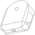
图2为本发明数控加工中心在线加工变形检测装置数控加工中心刀柄结构示意图。Fig. 2 is a schematic diagram of the structure of the tool holder of the numerical control machining center of the online machining deformation detection device of the numerical control machining center of the present invention.
图3为本发明数控加工中心在线加工变形检测装置角度调节器结构示意图。FIG. 3 is a schematic structural diagram of the angle adjuster of the online machining deformation detection device of the numerical control machining center of the present invention.
图4为本发明数控加工中心在线加工变形检测装置激光发射接收器结构示意图。FIG. 4 is a schematic diagram of the structure of the laser transmitter receiver of the online machining deformation detection device of the numerical control machining center according to the present invention.
图5为本发明数控加工中心在线加工变形检测流程示意图。FIG. 5 is a schematic diagram of the flow chart of the online machining deformation detection of the numerical control machining center of the present invention.
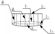
图6为本发明数控加工中心在线加工变形检测原理示意图。FIG. 6 is a schematic diagram of the principle of on-line processing deformation detection of the numerical control machining center of the present invention.
图7为本发明数控加工中心在线加工变形检测及补偿方法在线测量-误差补偿流程图。FIG. 7 is a flow chart of the online measurement and error compensation of the online machining deformation detection and compensation method of the numerical control machining center of the present invention.
图中1-数控加工中心刀柄、2-角度调节器、3-角度调节手柄、4-激光发射接收器、5-激光发射口、6-激光信号接收口、7-信号输出接线口。In the figure, 1- CNC machining center tool handle, 2- angle adjuster, 3- angle adjustment handle, 4- laser transmitter receiver, 5- laser transmitter port, 6- laser signal receiving port, 7- signal output wiring port.
具体实施方式Detailed ways
具体的,本发明的装置数控加工中心在线加工变形检测装置,如图1~图4所示,包括数控加工中心刀柄1、角度调节器2、角度调节手柄3、激光发射接收器4、激光发射口5、激光信号接收口6以及信号输出接线口7,所述数控加工中心刀柄1与角度调节器2连接,所述角度调节器2的外部设置有角度调节手柄3,角度调节器2的一端设置有凹槽;所述激光发射接收器4与角度调节手柄3连接,设置在角度调节器2的凹槽内部,激光发射接收器4端面设置有激光发射口5和激光信号接收口6,侧面设置有信号输出接线口7。Specifically, the device of the present invention is a numerical control machining center on-line machining deformation detection device, as shown in Figures 1 to 4, including a numerical control machining
其中,所述的数控加工中心在线加工变形检测装置的各部分装配零件基准面重要尺寸精度<0.005mm,形位精度<0.005mm。数控加工中心刀柄1为所有机床各型号均实用刀柄。Among them, the important dimensional accuracy of the reference plane of the assembly parts of each part of the online machining deformation detection device of the numerical control machining center is less than 0.005mm, and the shape and position accuracy is less than 0.005mm. CNC machining
本发明的方法数控加工中心在线加工变形检测及补偿方法,如图5~图7所示,包括以下步骤,且以下步骤顺次进行,The method of the present invention for detecting and compensating for online machining deformation of a numerical control machining center, as shown in Figures 5 to 7, includes the following steps, and the following steps are performed in sequence:
步骤一、首先对零件图纸尺寸公差,形位公差进行分析,及尺寸标注,建立三维模型;
步骤二:采用校准块进行数控加工中心在线加工变形检测装置校准,校准块的尺寸及型面精度为0.001mm;Step 2: Use a calibration block to calibrate the online machining deformation detection device of the CNC machining center, and the size and profile accuracy of the calibration block are 0.001mm;
步骤三:调节角度调节器2,使其激光光路垂直于检测表面,其中角度调节器2装配面精度为0.001mm,旋转角精度为1″,光路与被测工件表面垂直度为0.001mm;Step 3: Adjust the
步骤四:利用步骤一建立的三维模型测量路径程序,通过编写的程序点位路径进行测量点数据提取,测量点数据提取值为一次以上点位测量数据的均值;Step 4: Use the three-dimensional model measurement path program established in
步骤五:计算测量点坐标差值用于确定各工件坐标位置变形量;如图6所示,图中l1为补偿轨迹,l2为测量平行轨迹,l3为理论加工轮廓,l4为实际加工变形;d1为理论距离,d2为实际测量距离,Δ为变形量,Δ=d2-d1;Step 5: Calculate the coordinate difference value of the measuring point to determine the deformation amount of each workpiece coordinate position; as shown in Figure6 ,l1 is the compensation track in the figure,l2 is the measurement parallel track, l3 is the theoretical machining contour,l4 is the Actual processing deformation; d1 is the theoretical distance, d2 is the actual measurement distance, Δ is the deformation amount, Δ=d2 -d1 ;
步骤六:步骤六获得的变形量与原模型数据对比进行误差补偿,为实际加工偏差补偿;Step 6: Comparing the deformation amount obtained in
步骤七:利用补偿量精加工外轮廓结构。Step 7: Use the compensation amount to finish the outer contour structure.
以上所述,仅为本发明部分具体实施方式,但本发明的保护范围并不局限于此,任何熟悉本领域的人员在本发明揭露的技术范围内,可轻易想到的变化或替换,都应涵盖在本发明的保护范围内。The above description is only a part of the specific embodiments of the present invention, but the protection scope of the present invention is not limited to this. Any person familiar with the art within the technical scope disclosed by the present invention can easily think of changes or substitutions. Included in the protection scope of the present invention.
Claims (6)
Translated fromChinesePriority Applications (1)
| Application Number | Priority Date | Filing Date | Title |
|---|---|---|---|
| CN202010097988.3ACN111230594A (en) | 2020-02-17 | 2020-02-17 | On-line machining deformation detection device and compensation method of CNC machining center |
Applications Claiming Priority (1)
| Application Number | Priority Date | Filing Date | Title |
|---|---|---|---|
| CN202010097988.3ACN111230594A (en) | 2020-02-17 | 2020-02-17 | On-line machining deformation detection device and compensation method of CNC machining center |
Publications (1)
| Publication Number | Publication Date |
|---|---|
| CN111230594Atrue CN111230594A (en) | 2020-06-05 |
Family
ID=70878208
Family Applications (1)
| Application Number | Title | Priority Date | Filing Date |
|---|---|---|---|
| CN202010097988.3APendingCN111230594A (en) | 2020-02-17 | 2020-02-17 | On-line machining deformation detection device and compensation method of CNC machining center |
Country Status (1)
| Country | Link |
|---|---|
| CN (1) | CN111230594A (en) |
Cited By (1)
| Publication number | Priority date | Publication date | Assignee | Title |
|---|---|---|---|---|
| CN113009881A (en)* | 2021-01-27 | 2021-06-22 | 北京动力机械研究所 | Automatic setting and online measuring method for coordinate system in numerical control machining |
Citations (8)
| Publication number | Priority date | Publication date | Assignee | Title |
|---|---|---|---|---|
| CN104400563A (en)* | 2014-10-29 | 2015-03-11 | 北京工研精机股份有限公司 | On-line compensation method for deformation in machine tool processing process |
| CN104759942A (en)* | 2015-04-22 | 2015-07-08 | 华中科技大学 | Online milling deformation measurement and complementation machining method for thin-walled part |
| CN105081888A (en)* | 2015-09-02 | 2015-11-25 | 上海交通大学 | Two-dimensional vibration auxiliary laser scanning in-situ detection system and detection method thereof |
| CN106002491A (en)* | 2016-05-25 | 2016-10-12 | 哈尔滨理工大学 | Thin-wall part machining error measuring device and thin-wall part machining error measurement method based on spatial light modulator |
| CN106541300A (en)* | 2015-09-18 | 2017-03-29 | 天津航天长征火箭制造有限公司 | A kind of deformation-compensated method of large-scale wallboard Flank machining |
| CN107553220A (en)* | 2017-09-04 | 2018-01-09 | 四川大学 | A kind of Digit Control Machine Tool composition error real-time compensation method |
| CN108581637A (en)* | 2018-04-27 | 2018-09-28 | 华中科技大学 | A kind of laser displacement sensor on-machine measurement system |
| CN109648399A (en)* | 2019-02-25 | 2019-04-19 | 南京航空航天大学 | Five-axis linkage machine tools dynamic error and quiescent error method for comprehensive detection |
- 2020
- 2020-02-17CNCN202010097988.3Apatent/CN111230594A/enactivePending
Patent Citations (8)
| Publication number | Priority date | Publication date | Assignee | Title |
|---|---|---|---|---|
| CN104400563A (en)* | 2014-10-29 | 2015-03-11 | 北京工研精机股份有限公司 | On-line compensation method for deformation in machine tool processing process |
| CN104759942A (en)* | 2015-04-22 | 2015-07-08 | 华中科技大学 | Online milling deformation measurement and complementation machining method for thin-walled part |
| CN105081888A (en)* | 2015-09-02 | 2015-11-25 | 上海交通大学 | Two-dimensional vibration auxiliary laser scanning in-situ detection system and detection method thereof |
| CN106541300A (en)* | 2015-09-18 | 2017-03-29 | 天津航天长征火箭制造有限公司 | A kind of deformation-compensated method of large-scale wallboard Flank machining |
| CN106002491A (en)* | 2016-05-25 | 2016-10-12 | 哈尔滨理工大学 | Thin-wall part machining error measuring device and thin-wall part machining error measurement method based on spatial light modulator |
| CN107553220A (en)* | 2017-09-04 | 2018-01-09 | 四川大学 | A kind of Digit Control Machine Tool composition error real-time compensation method |
| CN108581637A (en)* | 2018-04-27 | 2018-09-28 | 华中科技大学 | A kind of laser displacement sensor on-machine measurement system |
| CN109648399A (en)* | 2019-02-25 | 2019-04-19 | 南京航空航天大学 | Five-axis linkage machine tools dynamic error and quiescent error method for comprehensive detection |
Cited By (1)
| Publication number | Priority date | Publication date | Assignee | Title |
|---|---|---|---|---|
| CN113009881A (en)* | 2021-01-27 | 2021-06-22 | 北京动力机械研究所 | Automatic setting and online measuring method for coordinate system in numerical control machining |
Similar Documents
| Publication | Publication Date | Title |
|---|---|---|
| CN102785128B (en) | The part processing precision on-line detecting system of NC Machine lathe and detection method | |
| CN100387931C (en) | A high-precision measurement method for large-scale free-form surfaces | |
| CN115562161A (en) | Tool cutting path machining error compensation method based on online monitoring | |
| CN102001021A (en) | Method for measuring geometric error parameter value of rotary oscillation axis of five-axis linkage numerical control machine tool | |
| CN111451880B (en) | AB double-tool pendulum five-axis magnetorheological polishing machine tool structure parameter calibration method | |
| CN105290968B (en) | A centering method for workpiece spindle and tool system of horizontal precision grinding and polishing machine tool | |
| WO2024066181A1 (en) | Method for in-position non-contact detection of symmetry of keyway of shaft workpiece | |
| CN103197601B (en) | Cutter shaft swings five-coordinate numerally controlled machine tool pendulum length assay method | |
| CN111390250A (en) | Weak rigidity thin-walled structural member, its processing method, and station quick-change positioning and clamping device | |
| CN105397549A (en) | Zero searching method of machine tool machined hole surface workpiece | |
| CN109531240A (en) | It is a kind of for measuring the exemplar and error separating method of five-axle number control machine tool Thermal Error | |
| CN113985813B (en) | Machine tool origin error compensation method based on-machine detection | |
| CN115365941A (en) | Automatic workpiece pose calibration method for optical polishing | |
| CN108332688A (en) | A kind of ball line slideway auxiliary raceway straightness On-line Measuring Method | |
| CN108723414A (en) | Ensure the processing technology of numerically-controlled machine tool precision box parts main aperture system position of related features | |
| CN115922439A (en) | Testing Method for Machining Accuracy of CNC Five-Axis Machine Tool | |
| CN111060010A (en) | Parallel plane parameter on-machine measurement system and measurement method | |
| CN111070210A (en) | Workpiece positioning and calibrating method | |
| CN107900781B (en) | Calibration device and calibration method of contact online detection system for lathes | |
| CN109945839B (en) | Method for measuring attitude of butt-jointed workpiece | |
| JP2011206862A (en) | Method of positioning rotary tool in multishaft processing machine | |
| CN111230594A (en) | On-line machining deformation detection device and compensation method of CNC machining center | |
| CN216846033U (en) | Inner wall measurement system based on deep sagittal workpiece | |
| CN114227339B (en) | Ultra-precision turning precise tool setting method based on trial-cut circular groove | |
| CN207982928U (en) | The caliberating device of contact on-line detecting system for lathe |
Legal Events
| Date | Code | Title | Description |
|---|---|---|---|
| PB01 | Publication | ||
| PB01 | Publication | ||
| SE01 | Entry into force of request for substantive examination | ||
| SE01 | Entry into force of request for substantive examination | ||
| RJ01 | Rejection of invention patent application after publication | Application publication date:20200605 | |
| RJ01 | Rejection of invention patent application after publication |