CN111227901B - Power Surgical Handpieces, Holders and Cutting Accessories - Google Patents
Power Surgical Handpieces, Holders and Cutting AccessoriesDownload PDFInfo
- Publication number
- CN111227901B CN111227901BCN202010096011.XACN202010096011ACN111227901BCN 111227901 BCN111227901 BCN 111227901BCN 202010096011 ACN202010096011 ACN 202010096011ACN 111227901 BCN111227901 BCN 111227901B
- Authority
- CN
- China
- Prior art keywords
- shaft
- collet
- drive shaft
- foot
- opening
- Prior art date
- Legal status (The legal status is an assumption and is not a legal conclusion. Google has not performed a legal analysis and makes no representation as to the accuracy of the status listed.)
- Active
Links
- 238000005520cutting processMethods0.000titleclaimsabstractdescription70
- 230000033001locomotionEffects0.000claimsdescription21
- 230000007423decreaseEffects0.000claimsdescription9
- 230000007704transitionEffects0.000claimsdescription6
- 230000000717retained effectEffects0.000claims1
- 210000002683footAnatomy0.000description55
- 210000001519tissueAnatomy0.000description29
- 238000000034methodMethods0.000description18
- 210000003423ankleAnatomy0.000description16
- 230000008878couplingEffects0.000description13
- 238000010168coupling processMethods0.000description13
- 238000005859coupling reactionMethods0.000description13
- 230000014759maintenance of locationEffects0.000description13
- 230000005540biological transmissionEffects0.000description11
- 238000002324minimally invasive surgeryMethods0.000description9
- 239000011800void materialSubstances0.000description9
- 210000003811fingerAnatomy0.000description8
- 238000001356surgical procedureMethods0.000description8
- 230000008901benefitEffects0.000description6
- 230000000295complement effectEffects0.000description5
- 238000006073displacement reactionMethods0.000description5
- 238000005452bendingMethods0.000description4
- 238000003780insertionMethods0.000description4
- 230000037431insertionEffects0.000description4
- 238000004519manufacturing processMethods0.000description4
- 230000008569processEffects0.000description4
- 230000000712assemblyEffects0.000description2
- 238000000429assemblyMethods0.000description2
- 238000010276constructionMethods0.000description2
- 239000000463materialSubstances0.000description2
- 210000004872soft tissueAnatomy0.000description2
- 206010002091AnaesthesiaDiseases0.000description1
- 229910001103M42 high speed steelInorganic materials0.000description1
- 230000009471actionEffects0.000description1
- 230000037005anaesthesiaEffects0.000description1
- 230000000903blocking effectEffects0.000description1
- 230000008859changeEffects0.000description1
- 230000006835compressionEffects0.000description1
- 238000007906compressionMethods0.000description1
- 230000001143conditioned effectEffects0.000description1
- FOIPWTMKYXWFGC-UHFFFAOYSA-NcreatinolfosfateChemical compoundNC(=N)N(C)CCOP(O)(O)=OFOIPWTMKYXWFGC-UHFFFAOYSA-N0.000description1
- 230000001627detrimental effectEffects0.000description1
- 230000000694effectsEffects0.000description1
- 230000008030eliminationEffects0.000description1
- 238000003379elimination reactionMethods0.000description1
- 208000015181infectious diseaseDiseases0.000description1
- 239000002184metalSubstances0.000description1
- 230000004048modificationEffects0.000description1
- 238000012986modificationMethods0.000description1
- 210000000056organAnatomy0.000description1
- 230000003534oscillatory effectEffects0.000description1
- 238000007142ring opening reactionMethods0.000description1
- 238000000926separation methodMethods0.000description1
- 238000004513sizingMethods0.000description1
- 229910001220stainless steelInorganic materials0.000description1
- 239000010935stainless steelSubstances0.000description1
- 210000003813thumbAnatomy0.000description1
- XLYOFNOQVPJJNP-UHFFFAOYSA-NwaterSubstancesOXLYOFNOQVPJJNP-UHFFFAOYSA-N0.000description1
Images


Classifications
- A—HUMAN NECESSITIES
- A61—MEDICAL OR VETERINARY SCIENCE; HYGIENE
- A61B—DIAGNOSIS; SURGERY; IDENTIFICATION
- A61B17/00—Surgical instruments, devices or methods
- A61B17/16—Instruments for performing osteoclasis; Drills or chisels for bones; Trepans
- A61B17/1613—Component parts
- A61B17/162—Chucks or tool parts which are to be held in a chuck
- A—HUMAN NECESSITIES
- A61—MEDICAL OR VETERINARY SCIENCE; HYGIENE
- A61B—DIAGNOSIS; SURGERY; IDENTIFICATION
- A61B17/00—Surgical instruments, devices or methods
- A61B17/16—Instruments for performing osteoclasis; Drills or chisels for bones; Trepans
- A61B17/1613—Component parts
- A61B17/1615—Drill bits, i.e. rotating tools extending from a handpiece to contact the worked material
- A—HUMAN NECESSITIES
- A61—MEDICAL OR VETERINARY SCIENCE; HYGIENE
- A61B—DIAGNOSIS; SURGERY; IDENTIFICATION
- A61B17/00—Surgical instruments, devices or methods
- A61B17/16—Instruments for performing osteoclasis; Drills or chisels for bones; Trepans
- A61B17/1613—Component parts
- A61B17/1622—Drill handpieces
- A—HUMAN NECESSITIES
- A61—MEDICAL OR VETERINARY SCIENCE; HYGIENE
- A61B—DIAGNOSIS; SURGERY; IDENTIFICATION
- A61B17/00—Surgical instruments, devices or methods
- A61B17/16—Instruments for performing osteoclasis; Drills or chisels for bones; Trepans
- A61B17/1613—Component parts
- A61B17/1628—Motors; Power supplies
- A—HUMAN NECESSITIES
- A61—MEDICAL OR VETERINARY SCIENCE; HYGIENE
- A61B—DIAGNOSIS; SURGERY; IDENTIFICATION
- A61B17/00—Surgical instruments, devices or methods
- A61B17/16—Instruments for performing osteoclasis; Drills or chisels for bones; Trepans
- A61B17/1613—Component parts
- A61B17/1631—Special drive shafts, e.g. flexible shafts
- A—HUMAN NECESSITIES
- A61—MEDICAL OR VETERINARY SCIENCE; HYGIENE
- A61B—DIAGNOSIS; SURGERY; IDENTIFICATION
- A61B17/00—Surgical instruments, devices or methods
- A61B2017/00477—Coupling
Landscapes
- Health & Medical Sciences (AREA)
- Surgery (AREA)
- Life Sciences & Earth Sciences (AREA)
- Biomedical Technology (AREA)
- Medical Informatics (AREA)
- Orthopedic Medicine & Surgery (AREA)
- Oral & Maxillofacial Surgery (AREA)
- Engineering & Computer Science (AREA)
- Dentistry (AREA)
- Heart & Thoracic Surgery (AREA)
- Nuclear Medicine, Radiotherapy & Molecular Imaging (AREA)
- Molecular Biology (AREA)
- Animal Behavior & Ethology (AREA)
- General Health & Medical Sciences (AREA)
- Public Health (AREA)
- Veterinary Medicine (AREA)
- Surgical Instruments (AREA)
- Dental Tools And Instruments Or Auxiliary Dental Instruments (AREA)
Abstract
Description
Translated fromChinese本申请是申请日为2015年7月27日、申请号为201580050298.X、发明名称为“具有便于装配到工具的切割附件对准的卡持器的电动手术手持件”的发明专利申请的分案申请。This application is a branch of an invention patent application with an application date of July 27, 2015, an application number of 201580050298.X, and an invention title of "Electric Surgical Handpiece with a Holder Facilitating the Alignment of a Cutting Attachment Fitted to a Tool". case application.
技术领域technical field
本发明总体涉及选择性附连切割附件的手术工具系统。更具体的,本发明涉及一种具有切割附件的手术工具系统,所述切割附件配置成便于附件与将附件保持到工具手持件的卡持器的对准。The present invention generally relates to surgical tool systems for selectively attaching cutting attachments. More specifically, the present invention relates to a surgical tool system having a cutting attachment configured to facilitate alignment of the attachment with a retainer that holds the attachment to a tool handpiece.
背景技术Background technique
在现代手术中,医疗人员可用的最重要的仪器之一是电动手术工具。通常,这种工具包括其中容置电机的手持件。紧固到手持件的是切割附件。切割附件被设计用于施加在患者的手术部位以完成特定医疗任务。一些电动手术工具设有钻子或小钻,以用于在硬组织中切割孔或用于选择性地移除硬组织和软组织。其它电动手术工具还设有锯片作为切割附件。这些工具用于分离大段的硬组织和/或软组织。对患者使用电动手术工具的能力减轻医师和其它医疗人员在对患者执行程序时的身体劳损。而且,利用电动手术工具比利用在它们之前的手动手术工具能够更快、且更准确地执行大多数手术程序。In modern surgery, one of the most important instruments available to medical personnel are powered surgical tools. Typically, such tools include a handpiece in which the motor is housed. Fastened to the hand piece is a cutting attachment. Cutting attachments are designed to be applied to a patient's surgical site to accomplish specific medical tasks. Some powered surgical tools are provided with drills or drills for cutting holes in hard tissue or for selectively removing hard and soft tissue. Other powered surgical tools also have saw blades as cutting attachments. These tools are used to separate large sections of hard and/or soft tissue. The ability to use powered surgical tools on a patient reduces physical strain on physicians and other medical personnel while performing procedures on patients. Furthermore, most surgical procedures can be performed faster and more accurately with powered surgical tools than with manual surgical tools that preceded them.
通过引用结合于此的、在1999年3月30日公布的名为MULTI-PURPOSE SURGICALTOOL SYSTEM的美国专利No.5,888,200公开了一种设计用于多种不同应用的手术工具系统。这种工具系统包括其中容置电机的手持件。手持件也包括用于将附件的轴选择性地联接到电机轴的第一联接组件。这种手持件也包括第二联接组件。第二联接组件用于将附连件选择性地紧固到手持件的前端。这个附连件可包括其自身的驱动轴和附件联接组件。这些附连件是细长附连件、成角度附连件和/或能够致动锯片。因此,提供这种类型的工具系统的优点在于,单一手持件能够用于驱动多个不同切割附件且协助以特定手术程序所需或期望的方式将附件定位在手术部位处。US Patent No. 5,888,200, issued March 30, 1999, entitled MULTI-PURPOSE SURGICALTOOL SYSTEM, incorporated herein by reference, discloses a surgical tool system designed for a variety of different applications. Such a tool system includes a handpiece in which a motor is housed. The handpiece also includes a first coupling assembly for selectively coupling the shaft of the accessory to the motor shaft. The handpiece also includes a second coupling assembly. A second coupling assembly is used to selectively secure the attachment to the forward end of the handpiece. This attachment may include its own drive shaft and accessory coupling assembly. These attachments are elongated attachments, angled attachments and/or capable of actuating the saw blade. Accordingly, an advantage of providing this type of tool system is that a single handpiece can be used to drive a number of different cutting attachments and assist in positioning the attachments at the surgical site in the manner required or desired for a particular surgical procedure.
对这种工具系统的变型在2003年5月13日公布的名为CUTTING ATTACHMENT FOR ASURGICAL HANDPIECE DESIGNED TO BE SELECTIVELY COUPLED TO THE HANDPIECE的美国专利No.6,562,055中公开,其内容也通过引用明确结合于此。这份文献公开了一种具有驱动轴的手术工具,所述驱动轴具有细长孔。驱动轴孔尺寸化为接收附件的轴的近端。夹头安装到驱动轴以与驱动轴一起旋转。夹头具有向驱动轴孔中突伸的足部。这个组件还设计成使得附件轴能够相对于夹头足部选择性地纵向定位。这个附件形成为具有沿驱动轴的长度纵向布置的数个保持特征部。这些特征部允许医师选择性地设定附件轴在手持件的前部延伸的程度。特别的,医师可能想要设定附件轴的远端在手持件轴的前部延伸相对短的距离,附件轴的远端是附连组织操作构件的一端。附件通过定位附件轴如此设定,以使得远侧定位的保持特征部由夹头足部接合。替换性的,医师能够重新定位切割附件,以使得组织操作构件远离手持件相对长距离地定位。为了如此配置系统,轴相对于夹头纵向设定,使得近侧定位的保持特征部是夹头足部抵靠接合的保持特征部。A variation on this tool system is disclosed in U.S. Patent No. 6,562,055, entitled CUTTING ATTACHMENT FOR ASURGICAL HANDPIECE DESIGNED TO BE SELECTIVELY COUPLED TO THE HANDPIECE, issued May 13, 2003, the contents of which are also expressly incorporated herein by reference. This document discloses a surgical tool having a drive shaft with an elongated bore. The drive shaft hole is sized to receive the proximal end of the shaft of the accessory. The collet is mounted to the drive shaft for rotation therewith. The collet has a foot projecting into the drive shaft bore. This assembly is also designed to enable selective longitudinal positioning of the accessory shaft relative to the collet foot. This attachment is formed with several retention features arranged longitudinally along the length of the drive shaft. These features allow the physician to selectively set the extent to which the accessory shaft extends across the front of the handpiece. In particular, the physician may wish to configure the distal end of the accessory shaft, which is the end to which the tissue manipulation member is attached, to extend a relatively short distance forward of the handpiece shaft. The accessory is positioned by positioning the accessory shaft such that the distally positioned retention feature is engaged by the collet foot. Alternatively, the physician can reposition the cutting attachment so that the tissue manipulation member is located a relatively long distance away from the handpiece. To configure the system so, the shaft is positioned longitudinally relative to the collet such that the proximally positioned retention feature is the retention feature against which the collet foot engages.
以上结构的优点在于,单一切割附件能够定位成使得附件头部距手持件不同距离地定位。这消除提供构造成使得仅两个不同附件之间的距离是附件轴的整体长度的数个切割附件的需要。An advantage of the above structure is that a single cutting attachment can be positioned such that the attachment head is positioned at different distances from the handpiece. This eliminates the need to provide several cutting attachments configured such that the only distance between two different attachments is the entire length of the attachment shaft.
以上类型的手术工具系统在附件具有刚性轴时工作良好。Surgical tool systems of the above type work well when the attachment has a rigid shaft.
然而,多个不同的手术工具系统设有切割附件,所述切割附件具有相对薄和/或柔性的轴。设有这种类型的薄柔性切割附件轴的手术工具系统的一种类型微创手术(MIS)工具系统。MIS工具系统如由其名字指示的设计成通过在患者中形成的称为门的相对小的开口施加到患者中的手术部位。执行MIS程序背后的目标是最小化切口的尺寸,所述切口形成在患者中以接近待执行程序的患者内部的部位。这个目标被期望的一个原因在于,其减小在手术之后患者组织需要回到其初始状态和痊愈的程度。执行MIS程序的另一优点是,与形成较大切口的程序相反的,MIS程序减轻身体内部的组织和器官暴露到周围环境的程度。引申开来,这减小患者组织面向感染的程度。However, a number of different surgical tool systems are provided with cutting attachments having relatively thin and/or flexible shafts. One type of minimally invasive surgery (MIS) tool system provided with this type of thin flexible cutting attachment shaft surgical tool system. The MIS tool system, as indicated by its name, is designed to be applied to the surgical site in the patient through a relatively small opening called a door formed in the patient. The goal behind performing an MIS procedure is to minimize the size of the incisions made in the patient to access the site inside the patient where the procedure is to be performed. One reason this goal is desirable is that it reduces the degree to which patient tissue needs to return to its original state and heal after surgery. Another advantage of performing an MIS procedure is that it reduces the exposure of tissues and organs inside the body to the surrounding environment, as opposed to procedures that make larger incisions. By extension, this reduces the exposure of the patient's tissue to infection.
设计成执行MIS程序的许多工具的截面宽度是相对小的。这协助工具装配在形成在患者中的相对小直径门中。一些MIS工具设计成插入具有2cm或更小直径的圆形开口中。这些工具自身可具有0.5cm或更小的截面直径。The section width of many tools designed to perform MIS procedures is relatively small. This assists the tool to fit in the relatively small diameter portal formed in the patient. Some MIS tools are designed to be inserted into circular openings with a diameter of 2 cm or less. The tools themselves may have a cross-sectional diameter of 0.5 cm or less.
存在一种包括切割附件的电动手术工具,所述切割附件设计成坐置在这些小直径孔中。通常这种类型的工具系统具有设计成可释放地附连到手持件的前端附连件。切割附件由手持件电机旋转且在附连件内旋转。这些附连件中的一些具有形成有弯折部的纵向轴线。附件轴是柔性的,以使得随着轴弯折,附件被弯折或成角度。There are powered surgical tools that include cutting appendages designed to sit in these small diameter holes. Typically this type of tool system has a nose attachment designed to releasably attach to the handpiece. The cutting attachment is rotated by the handpiece motor and within the attachment. Some of these attachments have a longitudinal axis formed with a bend. The accessory shaft is flexible such that as the shaft flexes, the accessory is bent or angled.
为了附件轴弯折或弯曲、或装配在小直径附连件内,附件轴的直径通常设计成相对小的。一些附件轴的柔性区段具有2mm或更小的直径。The diameter of the accessory shaft is usually designed to be relatively small in order for the accessory shaft to bend or bend, or to fit within a small diameter attachment. The flexible section of some accessory shafts has a diameter of 2mm or less.
由于这些附件轴的小尺寸和可弯曲性产生问题。这些轴当插入手持件中时能够弯曲或旋转。这种弯曲大致远离穿过轴的纵向轴线。旋转大致围绕纵向轴线。弯曲能够在将附件插入手持件中的过程期间发生。当弯曲发生时,可能需要旋转轴以将轴放置到一位置,在所述位置中,保持特征部与一体于卡持器的互补性保持特征部对准。必须采用这个动作会促增执行手术程序耗费的总体时间。增加时间以将对程序执行这个任务不利于现代手术的目标之一。特别的,现代手术的目标是尽可能快的执行程序,以最小化患者被保持在麻醉下和患者的身体打开且暴露到周围环境的时间。Problems arise due to the small size and bendability of these accessory shafts. These shafts can bend or rotate when inserted into the handpiece. This bending is generally away from the longitudinal axis passing through the shaft. The rotation is generally about the longitudinal axis. Bending can occur during the process of inserting the accessory into the handpiece. When bending occurs, it may be necessary to rotate the shaft to place the shaft into a position in which the retention features are aligned with complementary retention features integral to the retainer. Having to take this action contributes to the overall time it takes to perform the surgical procedure. Increasing the time it takes to perform this task on a procedure is detrimental to one of the goals of modern surgery. In particular, the goal of modern surgery is to perform the procedure as quickly as possible to minimize the time the patient is kept under anesthesia and the patient's body is open and exposed to the surrounding environment.
附件轴的非期望旋转能够在当手持件被致动时的程序期间发生。特别的,当手持件旋转时,整个附件轴应该以相同的速度旋转。然而,由于不同力实施到附件的不同部分上和附件轴的柔性性质,在附件轴中围绕轴的纵向轴线可能存在一些扭曲。由于这种扭曲和形成轴的材料扭回到非扭曲状态的天然倾向性,附件轴的近端、即布置在一体于手持件的驱动轴中的轴的一端可能想要在驱动轴内旋转。轴的这种旋转能够导致轴保持特征部旋转脱离与夹头足部或将轴保持就位的其它卡持器保持特征部的接合。如果这种类型的附件轴相对于驱动轴的移动发生,则附件轴可能不能牢固地保持就位到驱动轴。Undesired rotation of the accessory shaft can occur during a procedure when the handpiece is actuated. In particular, when the handpiece rotates, the entire attachment shaft should rotate at the same speed. However, due to the different forces applied to different parts of the accessory and the flexible nature of the accessory shaft, there may be some twisting in the accessory shaft about the longitudinal axis of the shaft. Due to this twisting and natural tendency of the material forming the shaft to twist back to an untwisted state, the proximal end of the accessory shaft, ie the end of the shaft disposed in the drive shaft integral to the handpiece, may want to rotate within the drive shaft. This rotation of the shaft can cause the shaft retaining feature to rotate out of engagement with the collet foot or other retainer retaining feature holding the shaft in place. If this type of movement of the accessory shaft relative to the drive shaft occurs, the accessory shaft may not hold securely in place to the drive shaft.
发明内容Contents of the invention
本发明涉及一种新的且有用的手术工具系统。本发明的手术工具系统包括电动手术手持件和由手持件旋转的切割附件。本发明的系统包括卡持器,所述卡持器具有一体于手持件的锁定构件。所述系统也包括一体于切割附件的保持特征部。卡持器锁定构件设计成接合附件保持特征部,以使得由于这种接合,附件随着锁定构件的旋转而旋转。本发明的系统还设计成使得手持件和切割附件具有互补性特征部,在切割附件装配到手持件时,互补性特征部将附件保持特征部与卡持器锁定构件对准。这些特征部也抑制附件相对于手持件锁定构件的相对旋转。The present invention relates to a new and useful surgical tool system. The surgical tool system of the present invention includes a powered surgical handpiece and a cutting attachment that is rotated by the handpiece. The system of the present invention includes a retainer having a locking member integral to the handpiece. The system also includes a retention feature integral to the cutting attachment. The retainer locking member is designed to engage the accessory retention feature such that due to this engagement, the accessory rotates as the locking member rotates. The system of the present invention is also designed such that the handpiece and cutting accessory have complementary features that align the accessory retaining feature with the retainer locking member when the cutting accessory is assembled to the handpiece. These features also inhibit relative rotation of the accessory with respect to the handpiece locking member.
在本发明的一些构造中,卡持器包括对准环圈。对准环圈在锁定构件的前部向远侧定位。对准环圈形成有非圆形开口。附件轴成形为使得轴的至少近侧区段的形状是非圆形的。更具体的,附件轴成形为紧密地滑动装配到对准环圈中的开口中。In some configurations of the invention, the retainer includes an alignment collar. The alignment ring is positioned distally on the front of the locking member. The alignment collar is formed with a non-circular opening. The accessory shaft is shaped such that at least a proximal section of the shaft is non-circular in shape. More specifically, the accessory shaft is shaped to snugly slide fit into the opening in the alignment collar.
对准环圈开口相对于卡持器锁定元件处于特定方位。附件轴上的保持特征部处于沿轴的对应位置。The alignment collar opening is at a particular orientation relative to the retainer locking element. Retaining features on the accessory shaft are in corresponding positions along the shaft.
作为准备本发明的工具系统以供使用的过程的一部分,附件轴插入卡持器对准环圈中。为了如此装配附件轴,通常需要旋转轴以使得轴的非圆形部分与对准环圈中的非圆形孔进行配准。一旦这个对准过程被完成,使轴滑动穿过环圈将是简单的。由于附件轴与卡持器对准环圈的对准,轴保持特征部与卡持器锁定元件对准。As part of the process of preparing the tool system of the present invention for use, the accessory shaft is inserted into the retainer alignment collar. To fit the accessory shaft in this way, it is often necessary to rotate the shaft so that the non-circular portion of the shaft registers with the non-circular hole in the alignment collar. Once this alignment process is complete, it is simple to slide the shaft through the collar. Due to the alignment of the accessory shaft with the retainer alignment collar, the shaft retaining feature is aligned with the retainer locking element.
卡持器对准环圈随着手持件输出轴的旋转而旋转。由于附件轴在环圈孔中的紧密装配,附件轴被环圈迫使与环圈一起旋转。这抑制近侧于环圈定位的附件轴的相对短长度区段的扭曲。这种扭曲的消除导致同样地消除这样的扭曲,所述扭曲可能引起附件轴从卡持器锁定元件脱离接合。The retainer alignment ring rotates as the handpiece output shaft rotates. Due to the tight fit of the accessory shaft in the collar hole, the accessory shaft is forced by the collar to rotate with the collar. This inhibits twisting of the relatively short length section of the accessory shaft positioned proximal to the loop. This elimination of twisting results in likewise eliminating twisting that could cause the accessory shaft to disengage from the retainer locking element.
在本发明的一些方案中,卡持器包括夹头,所述夹头具有像用作手持件锁定元件的足部那样的弹簧。In some aspects of the invention, the retainer includes a collet with a spring like foot acting as a handpiece locking element.
在本发明的一些方案中,卡持器可移除地附连到包含手持件电机的外壳。In some aspects of the invention, the retainer is removably attached to the housing containing the handpiece motor.
附图说明Description of drawings
本发明在权利要求中被指出特征性。本发明的上述和另外的特征及益处通过以下结合附图给出的详细说明被理解。除非另有说明,否则如在图中示出的部件的相对尺寸大致理解为部件与彼此的相对尺寸。在附图中:The invention is pointed out and characterized in the claims. The above and other features and benefits of the present invention will be understood from the following detailed description given in conjunction with the accompanying drawings. Relative dimensions of components as shown in the figures are generally to be understood as relative dimensions of the components to each other, unless otherwise indicated. In the attached picture:
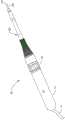
图1是本发明的手术工具系统的平面部图;1 is a plan view of the surgical tool system of the present invention;
图2是图1的系统的基础部件的分解图;Figure 2 is an exploded view of the basic components of the system of Figure 1;
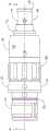
图3是这个系统的可移除卡持器的平面部图;Figure 3 is a plan view of the removable holder of this system;
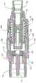
图4是卡持器的剖视图;Figure 4 is a sectional view of the holder;
图5是卡持器的分解图;Figure 5 is an exploded view of the holder;
图6是卡持器本体的透视图;Figure 6 is a perspective view of the holder body;
图7是卡持器本体的剖视图;Figure 7 is a sectional view of the holder body;
图8是卡持器本体的替换性透视图;Figure 8 is an alternative perspective view of the holder body;
图9是卡持器盖体的透视图;Figure 9 is a perspective view of the holder cover;
图10是卡持器盖体的剖视图;Figure 10 is a sectional view of the holder cover;
图11是卡持器弹簧圈的透视图;Figure 11 is a perspective view of the retainer coil;
图12是在卡持器内部的驱动轴的透视图;Figure 12 is a perspective view of the drive shaft inside the holder;
图13是驱动轴的剖视图;Figure 13 is a sectional view of the drive shaft;
图14是夹头的透视图;Figure 14 is a perspective view of the cartridge;
图15是夹头、对准环圈和驱动销的分解图;Figure 15 is an exploded view of the collet, alignment collar and drive pin;
图15A描绘了夹头的远端如何坐置在对准环圈中;Figure 15A depicts how the distal end of the collet is seated in the alignment ring;
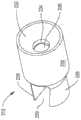
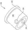
图16是对准环圈的透视图;Figure 16 is a perspective view of an alignment ring;
图17是对准环圈的远端的平面部图;Figure 17 is a plan view of the distal end of the alignment loop;
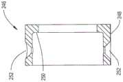
图18是对准环圈的剖视图;Figure 18 is a cross-sectional view of an alignment ring;
图19是卡持器锁定环圈的透视图;Figure 19 is a perspective view of the retainer locking ring;
图20是在卡持器内部的致动器的透视图;Figure 20 is a perspective view of the actuator inside the holder;
图21是致动器的剖视图;Figure 21 is a cross-sectional view of the actuator;
图22是在卡持器内部的传动杆的透视图;Figure 22 is a perspective view of the drive rod inside the holder;
图23是在卡持器内部的转矩环的透视图;Figure 23 is a perspective view of the torque ring inside the retainer;
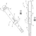
图24是手术工具系统的鼻部的剖视图;24 is a cross-sectional view of the nose of the surgical tool system;
图25是切割附件轴的远端的透视图;Figure 25 is a perspective view of the distal end of the cutting attachment shaft;
图26是向前方远侧看去的切割附件的近端的平面部图;以及Figure 26 is a plan view of the proximal end of the cutting attachment looking distally forward; and
图27是切割附件轴的近端的平面部图,其中,保持特征部的侧边缘可见。27 is a plan view of the proximal end of the cutting attachment shaft with the side edges of the retention features visible.
具体实施方式Detailed ways
本发明的手术工具系统40的基础部件通过参考图1和2可见。系统40包括手持件42。手持件42具有柱形本体44。在手持件本体44内部是由阴影线矩形描绘的电机46。电机46旋转由第二阴影线矩形描绘的驱动心轴48。卡持器60可移除地附连到手持件本体44的远端。("远侧"被理解为意味着远离握持手持件42的医师,朝向待执行程序的手术部位。"近侧"被理解为意味着朝向握持手持件42的医师,远离待执行程序的手术部位)。鼻部302可移除地附连到卡持器60的远端且从卡持器的远端向前延伸。切割附件320布置在鼻部302内侧。切割附件320联接到卡持器60、以及延伸穿过且伸出鼻部302的远端。定位在鼻部302的前部的组织操作构件338形成切割附件的远端。The basic components of the
在卡持器60内部是驱动轴134(图12)。驱动轴的近端配置成接合手持件心轴48且由手持件心轴旋转。下文描述的在卡持器60内部的部件将切割附件320可释放地保持到驱动轴134。电机46的致动因此致使切割附件320的旋转。Inside the
手持件42形成为使得本体44为大致柱形。本体44的远端如由图2中的虚线开口45描绘的打开。这允许卡持器60的近端被坐置在本体44中。驱动心轴48延伸到手持件的打开远端中。
手持件电机46是用于致动切割附件的任何合适的电机。电机46通常是电气动或液压驱动电机。线缆43可见为从手持件本体44的近端延伸。线缆43代表用于驱动电机的能量、气体或水来自于独立于本发明的系统40的操纵台。能够结合到手持件42中的一个这种电机在申请人的美国专利No.8,597,316中公开,所述专利在2013年12月2日发布,名为CUTTINGACCESSORYFOR FOR USE WITH A MEDICAL/SURGICAL POWERED HANDPIECE,THE ACCESSORYHAVING FEATURES THAT FACILITATE THE FINE OR COARSE ADJUSTMENT OF THEEXTENSION OF THE ACCESSORY SHAFT,其内容通过引用结合于此。能够用于将电能提供给电驱动电机的操纵台在申请人的美国专利No.7,422,582中公开,所述专利在2008年9月9日授权,CONTROL CONSOLE TO WHICH POWERED SURGICAL HANDPIECES ARE CONECTED,THECONSOLE CONFIGURED TO SIMULTANEOUSLYE NERGIZE MORE THAN ONE AND LESS THAN ALLOF THE HANDPIECES,其内容通过引用结合于此。再次,应该理解的是,手持件电机46的结构和给电机能量的组件不是本发明的一部分。
驱动心轴48由未示出且不是本发明的一部分的轴承可旋转地安装在本体44中。驱动心轴48可通过手持件本体44的打开端45接近。驱动心轴形成为具有从心轴的远端打开且从心轴的远端向近侧延伸的矩形闭合端孔49。Drive
卡持器60形成为具有在图3-5中可见的壳体62和盖体104,它们集成地形成卡持器的外壳的本体。在图6-8中最佳可见的壳体62由总体具有多个不同柱形区段的单一金属件形成。一个近侧柱形区段是足部64。足部64形成有从足部的外表面向内延伸和围绕足部周向延伸的两个凹部。这些凹部中的第一个是环形凹口66。第二凹部是凹槽68。在截面中,凹口66和凹槽68的形状都是矩形。壳体62形成为使得凹槽68从凹口66向前隔开且在长度上比凹口短。在图5中部分可见的孔69从足部的外表面侧向向内延伸。孔69在凹槽68的前部向远侧定位。壳体62在足部64的前部具有环圈70。环圈70具有比足部64的外径大的外径。在本发明的描绘方案中,环圈70的外径具有锥度。从环圈70的近端向远侧延伸,环圈的直径些许减小。The
壳体62在环圈70的前部具有头部72。头部72总体具有与足部64的直径大约相等的直径。头部在头部72近端的前部形成为具有螺旋形沟槽74。沟槽74围绕穿过壳体62的近侧至远侧的纵向轴线是对称的。壳体62还形成为使得邻近每个沟槽74存在止动部76(在图8中可见一个)。在沟槽74呈现在头部72中的前部,头部形成为具有周向延伸凹口78。在头部72的在凹口78前部的部分中,孔80侧向延伸穿过头部。The
唇部84从头部72向前延伸且形成壳体62的最远侧部分。唇部84具有比头部72的外径小的外径。唇部84形成有螺纹(未示出)。A
壳体62形成为具有多个连续孔,它们形成纵向延伸穿过壳体的通道。第一孔、即孔88从壳体的近端向前方远侧延伸。孔88因此定位在壳体足部64中。壳体62还形成为使得限定孔88的壳体内壁具有从孔88向外周向延伸的凹口90。凹口90与孔88连续且大约在孔的中间中定位。凹口90围绕孔88周向延伸。The
孔92从孔88的远端向前方远侧延伸。壳体62形成为使得孔92定位在壳体环圈70内。孔92具有比孔88的直径小的直径。孔92的远端向孔96中开通。孔96具有比孔88的直径小且比孔96的直径大的直径。壳体62还形成为以便限定在壳体的限定孔96的内壁中的凹槽94。凹槽94从孔88向孔96中开通处的孔96的近端向外延伸。凹槽94围绕孔96的外侧周向延伸。孔98从孔96的远端延伸到壳体62的远端。孔98具有比壳体孔88的直径大的直径。壳体62形成为使得孔98延伸穿过壳体头部72和远端唇部84两者。
现在参考图9和10描述的盖体104具有基部106。基部106的截面是大致圆形。盖体104还形成为使得随着基部106向远侧延伸,基部的外径存在些许减小。盖体在基部106的前部具有环圈110。环圈110是大致柱形且具有比基部的直径小的直径。盖体104还成形为使得环圈110的在基部106的紧邻前部的部分具有凹口108。凹口108围绕环圈110周向延伸。The
颈部112从盖体环圈110向前方远侧延伸。颈部112具有直径比环圈110的直径小的弯曲外表面。颈部112的外表面不是完全柱形。实际上,颈部112形成为具有两个平行的在直径上相反的平坦部114。平坦部114在颈部112的连接外弯曲区段的内部定位。A
柱形头部116从环圈110向前延伸。头部116具有比穿过颈部平坦部114的距离小的直径。在距头部的近端的前部大约4mm的短距离处,孔118侧向延伸穿过头部。孔118延伸到下文描述的孔117中。在头部116的远端处存在边沿120。边沿120从头部116径向向外突伸。A
孔105从盖体基部106的近端向前方远侧延伸。孔105具有比壳体头部72的直径大的直径。孔105的远端向孔107中开通。孔107具有比孔105的直径小的直径。限定孔107的盖体104的内柱形壁形成有螺纹(未示出)。更具体的,盖体孔107被尺寸化为适配壳体唇部84,以使得围绕壳体唇部84的互补性螺纹和孔接合。孔109从孔107向前延伸。孔109具有比孔107的直径小的直径。未标明的是孔107和109之间的切口。孔109具有锥度。因此,随着从孔107向远侧延伸,孔109的直径减小。
孔109的远端向孔111中开通。孔111的形状是柱形且具有与孔109的远端的直径相同的直径。孔111向孔115中开通。孔115具有比孔111的直径小的直径。切口113定位在孔111和113之间。The distal end of
孔117在孔115的前部延伸穿过盖体头部116。孔117具有变化直径的区段。包括孔117的盖体头部116形成为接收在鼻部302内部的部件308,所述部件用于将鼻部可释放地保持到卡持器60。A
销119被坐置在盖体孔118中。销119(图4)与鼻部联接特征部308协作以将鼻部302保持到卡持器60。The
在图11中最佳可见的柔性弹簧圈124卡扣装配在形成在壳体足部64中的凹口66中。弹簧圈124大致形式是具有延伸环长度的间断部126的柱形套筒。弹簧圈形成为使得在环的近端和远端处,,环的相应外表面128和130向内成锥度。形成系统40的部件尺寸化为使得当环124在卡持器足部64之上坐置时,弹簧圈124的主外环形表面129从足部向外突伸。这协助环卡扣装配到手持件本体44内部的开口45中且从所述开口拆卸。未示出的是在手持件本体44内部的抵接弹簧圈124的结构性特征部。这些表面是约束弹簧的移动以协助卡持器60可释放地附连到手持件42的表面。The
在图5中可见的O型圈125被坐置在壳体凹槽68中且伸出凹槽。O型圈125减弱卡持器60相对于手持件的震动。销127被坐置在壳体孔69中且伸出孔。销127与在手持件本体44内部的部件协作以防止卡持器60相对于手持件42的旋转。接合销127的在手持件本体内部的部件不是当前发明的一部分。An O-
如在图12和13中最佳可见,卡持器驱动轴134是一件式单元。驱动轴在近端处形成为具有腿部136。腿部136是大致柱形。在轴134的近端处,腿部136形成为使得两个平行的平坦部138(一个可见)从腿部的近端向前延伸。腿部的近侧部分、即其中呈现平坦部138的部分尺寸化为滑动装配在手持件驱动心轴孔49中,所以心轴48和驱动轴腿部之间存在最小间隙。未标明但是在图12和13中可见的是从驱动轴134的近端向前方远侧延伸的孔。这孔不是当前发明的一部分。As best seen in Figures 12 and 13, the
驱动心轴在腿部136的前部具有腰部区段139。腰部区段139的形状是柱形且具有比腿部136的直径大的直径。驱动轴在腰部区段的前部具有躯干部142。躯干部142的形状是柱形且具有比腰部区段139的直径大的直径。出于制造目的呈现的切口144将腰部区段139和躯干部142分开。也出于制造原因呈现的切口140将腿部136从腰部区段139分开。躯干部142在切口144的前部形成有两个对称相反的椭圆形开口146。躯干部142成形为使得开口146的主轴线平行于穿过驱动轴134的近侧至远侧纵向轴线。The drive spindle has a
驱动轴134还形成为具有在躯干部142的远端的紧邻前部定位的颈部150。颈部150从躯干部142径向向外突伸。未标明的是在躯干部142中近侧紧邻于颈部150的切口。颈部150具有面向近侧的外表面152。The
驱动轴134在颈部150的前部具有头部158。头部158的形状是柱形。头部158具有等于轴躯干部142的直径或比轴躯干部的直径小的直径。The
孔162从远端轴头部158向后方近侧延伸。孔162延伸穿过轴头部158和颈部150且部分穿过躯干部142。孔162的近端向孔166中开通。孔166与孔162共轴且在直径方面部比孔162小。在孔162的近端处的阶梯部164限定孔162和孔166之间的过渡。孔166在轴躯干部142的近端的前部的位置处终止。躯干部开口146向孔166中开通。
在图4和5中可见的两个轴承组件170将驱动轴134可旋转地保持到卡持器外壳。(未特别示出的是轴承组件170的内套和外套。在轴承组件170近侧定位的内套在驱动轴134的腰部区段139之上布置。在轴承组件170近侧定位的外套抵靠限定孔96的壳体62的内壁坐置。波形垫圈172(图5)近侧紧邻于近侧轴承组件170的近端地定位。波形垫圈172的外周边被坐置在壳体凹槽94中。波形垫圈的内周边被坐置在驱动轴凹槽140中。波形垫圈172抵靠驱动轴134以便向前方远侧推动驱动轴。Two bearing
远侧轴承组件170的内套围绕驱动轴头部158坐置。轴承组件的外表面抵靠限定孔111的盖体106的内柱形壁布置。形成卡持器60的部件尺寸化为使得驱动轴的远端在盖体106内部的切口113的后方隔开。An inner sleeve of
现在参考图14和15描述的夹头178可滑动地布置在驱动轴136中。夹头178将切割附件320可释放地保持到驱动轴。夹头178是包括基部182的一件式部件。基部182是柱形的且尺寸化为在驱动轴孔166内以最小侧向移动可滑动地装配。冠部180从夹头基部182的近端向前方近侧延伸一短距离。冠部180具有锥度以使得随着从基部182向近侧延伸,冠部的外表面的直径减小。孔184纵向延伸穿过冠部和基部182。孔184出于制造原因存在。孔184的存在也协助以下讨论的夹头腿部192的挠曲。孔186侧面至侧面地侧向延伸穿过夹头基部182。孔184和16交叉。夹头172形成为使得沟槽188从孔188向前方远侧延伸。沟槽188在从近侧向远侧延伸的平面上定位,夹头178的纵向中心轴线位于所述平面中。
两个腿部192从夹头基部182向前延伸。腿部192拱形地成形。由腿部的外表面限定的圆圈具有比基部182的直径小的直径。由腿部的面相反的内表面限定的圆圈限定空隙193,所述空隙的远端在图14中标明。在垂直于纵向轴线的平面中的截面中,空隙193的形状是大致圆形的。Two
踝部194和足部196定位在每个腿部192的远端处。每个踝部194具有与腿部的外表面平齐的外表面,足部从所述腿部的外表面延伸。如以下讨论的,足部196具有从踝部194的外表面径向向外延伸的外表面。每个踝部194和足部196具有一对相反侧面198。踝部194和足部196成形为使得侧面198相对于穿过踝部和足部的近侧至远侧纵向轴线成锥度。因此,在紧邻踝部194从之延伸的腿部处,相反侧面198之间的距离是相对短的,比穿过腿部的距离小。随着向远侧延伸,单一足部196的侧面198之间的距离增加。因此在夹头178的每个侧面上,相反踝部和足部的邻近侧表面限定凹陷部202,有一个在图14中标明。每个凹陷部202具有这样的形状,以使得穿过凹陷部的宽度沿凹陷部向远侧减小。凹陷部202能够被认为具有弯曲的楔形形状。An
每个足部196具有四个拱形成形的外表面。从踝部向远侧延伸的第一外表面、即表面204随着表面向远侧延伸向外成锥度,所述表面接近于垂直于穿过夹头178的纵向轴线。第二表面、即表面206具有沿表面206的长度基本恒定的曲率半径。向远侧延伸的第三表面、即表面208从表面206些许向外成锥度。表面208成锥度到第四表面、即表面210。表面210具有恒定直径。由相反表面210限定的圆圈具有比驱动轴孔162的直径小的、大约0.12mm的直径。这种尺寸化允许夹头腿部192、踝部194和足部196远离延伸穿过驱动轴136的纵向轴线向外挠曲。Each
每个足部196朝向夹头178的纵向轴线和相反足部196向内突伸。每个足部的最内表面被认为是指头部表面211。指头部表面211的形状均是凸起的。Each
也可滑动地布置在驱动轴136中的是参考图16-18描述的对准环圈212。对准环圈212具有柱形形状的头部230。更具体的,头部230尺寸化为在驱动轴孔192中纵向移动。腰部228从头部230向后方近侧地定位。腰部228成形为从头部230向近侧延伸地向内成锥度。一对相反足部226从腰部228向外延伸。足部226和腰部228组合成形为限定从环圈212的近端向远侧延伸的凹陷部229。凹陷部229尺寸化为接收相反的夹头踝部194和足部196。Also slidably disposed in the
对准环圈212还形成为具有从环圈的远端向内里近侧延伸的开口232。开口232具有锥度。随着开口232从头部230的远端向近侧延伸,开口232的直径减小。开口232终止在形状为柱形的孔234处。孔234的近端向孔236中开通。在截面中,在垂直于穿过对准环圈212的纵向轴线的平面中,孔236的形状是扁平椭圆。更具体的,孔236具有两个相反平行的侧面。两个弯曲端连接平行侧面。每个弯曲端对着大约120°的弧。仅在图18中标明的、在孔234的基部处的两个阶梯部限定孔234和孔236之间的过渡。孔236占据环圈头部232的总长度的大约三分之二的长度。孔236向凹陷部229中开通。The
当卡持器60被组装时,夹头178的基部和腿部坐置在驱动轴孔166中。夹头踝部194和足部196被布置在环圈凹陷部229中。同样布置在夹头孔162中的是对准环圈212。每个夹头踝部194和关联足部196被布置在对准环圈凹陷部229的一端中,如在图15和15A中可见的。如在图15A中最佳可见的,夹头178和对准环圈212还形成为使得当夹头和踝部194及足部196被坐置在环圈凹陷部229中时,踝部和足部远离限定表面的邻近凹陷部隔开。夹头侧表面198和对准环圈212的邻近表面之间存在狭窄分隔。夹头足部196的远端表面和对准环圈的邻近表面之间存在较宽的间隙。描绘的间隙出于示意目的被扩大。应该理解的是,夹头足部196能够相对于对准环圈足部226侧向挠曲。The base and legs of the
卡持器的多个部件协作以在驱动轴内纵向移动夹头178和对准环圈212。这些部件之一是现在参考图19描述的锁定环240。锁定环240的形状是套筒状的。锁定环240具有允许环在壳体头部72之上滑动装配且旋转的内径。锁定环240的外表面形成有滚花部242,以允许拇指和手指容易地旋转环。滚花部242大约沿环的最近侧五分之四延伸。环的最远侧五分之一是光滑的。Multiple parts of the holder cooperate to move
锁定环240还形成为使得两个凹槽244从环的内壁向内延伸且沿环的内壁纵向延伸。凹槽244相对于穿过环240的近侧至远侧的纵向轴线对称。在截面中、即在垂直于穿过锁定环的纵向轴线的平面中,凹槽244的形状是弯曲的。Locking
在图20和21中最佳可见的致动器246是第二部件,其是纵向移位夹头178和对准环圈212的组件的一部分。致动器246具有套筒状主体248。致动器主体248的外径尺寸化为允许致动器在壳体孔98内在紧密纵向滑动装配移动中接合。在主体248的远端处,致动器246具有从主体径向向内延伸的唇部250。致动器246还尺寸化为使得唇部的内径大约2.5mm比驱动轴躯干部142的外径大。
致动器246也具有两个对称相反的断削部252。每个断削部252是形式为球体的一小区段的空隙空间。每个断削部252示出为向致动器246的内部中开口。这个开口出于制造原因存在。The
当卡持器60被组装时,致动器246被坐置在壳体孔98中。在图5中最佳可见的球轴承256坐置在壳体螺旋形沟槽74的每个中。球轴承256尺寸化为从壳体头部72的外内表面两者向外突伸。每个球轴承256的从壳体头部向外突伸的部分坐置在锁定环凹槽244之一中。每个球轴承256的从限定壳体内表面的孔98向内突伸的部分坐置在断削部252之一中。因此,锁定环的旋转引起球轴承256在凹槽244中沿壳体纵向移动。球轴承256的纵向移动引起致动器246在壳体孔98中纵向移动。The
在图22中最佳可见的,传动杆258也可滑动地布置在壳体孔98中。传动杆258具有管状主体260。主体260的外表面具有比致动器唇部250的内径小的直径。主体260的内表面具有比驱动轴躯干部142的直径充分大的直径,使得传动杆能够在驱动轴134之上纵向自由移动。As best seen in FIG. 22 ,
传动杆258具有从主体260径向向外延伸的边沿262。边沿262定位在主体260的远端处。传动杆258还形成为具有两个共轴孔264。孔264在本体的近端的前部定位。孔264围绕公共轴线居中,所述公共轴线交叉于穿过传动杆258的近侧至远侧的纵向轴线。The
传动杆258布置在驱动轴躯干部142之上以在躯干部之上移动。传动杆258定位成使得传动杆边沿262在致动器唇部250的前部紧邻远侧地定位。形成卡持器的部件尺寸化为使得传动杆边沿262在致动器唇部250之上突伸。The
形成卡持器60的部件还设置成使得驱动轴开口146、夹头孔186和传动杆孔264配准。在图5和15中标明的驱动销266延伸穿过这些空隙。驱动销266紧密装配在夹头孔186和传动杆孔264中。驱动销266能够在驱动轴开口146内向近侧和远侧移动。驱动销266将驱动轴134的旋转运动传递到夹头178。驱动销266也将传动杆258的移动纵向传递到夹头178,以使得夹头与传动杆一致地移动。The components forming the
在图4和5中可见的两个盘簧268和270围绕驱动轴躯干部142布置。第一弹簧、即弹簧268就径向距离而言最接近于躯干部142的外柱形表面地定位。弹簧268的近端抵接传动杆258的边沿262。弹簧268的远端抵接驱动轴颈部150的环形近侧面向的表面152。弹簧268处于压缩中。弹簧268因此通常实施将传动杆258远离驱动轴颈部150向近侧地保持的力。由弹簧268施加的力能够被引起传动杆的纵向移位的手动力克服。Two
弹簧270在弹簧268的外部且围绕弹簧268定位。弹簧270的近端抵靠环状部布置,向远侧指向致动器246的表面。弹簧270的相反远端抵靠在盖体104内部的环状阶梯部布置,所述阶梯部是孔107和109之间的过渡。
也布置在衬套内侧的是在图23中可见的止动环274。如由其名字指示的,止动环274是环状的。止动环274形成有具有平坦部外面部276的多个区段。一个外面部276形成有朝向环274的中心延伸穿过环的开口278。止动环274还形成为以便具有从环的由远及近指向的面部向近侧延伸的闭合端孔280。Also disposed inside the bushing is a
止动环274在壳体头部72的凹口78前部的部分之上固定地布置在卡持器60中。穿过锁定环开口278延伸到壳体孔80中的销282(图5)保持止动环固定到壳体62。A
在图4和5中可见的盘簧284近侧于止动环274紧邻地定位。弹簧284具有两个相反腿部(未标明)。第一腿部向近侧延伸且布置在形成在锁定环240中的孔(孔不可见)中。第二腿部向远侧延伸且延伸到止动环孔280中。弹簧284置于锁定环240对抗锁定环旋转的力。弹簧284置于锁定环240上的力能够由施加到锁定环240的手指力克服,从而旋转锁定环。
如在图2和24中可见的鼻部302包括基部304。基部304的形状大致成锥形,因为随着从外表面的近端延伸,基部的直径减小。存在基部的恒定直径的部分304。在基部304的内侧具有空隙306和联接特征部308。空隙306和联接特征部308设计成协助鼻部基部304在盖体头部116和颈部112之上的可释放联接。将鼻部联接到卡持器60的特定装置不是本发明的一部分。因此,不进一步描述空隙306和联接特征部308。The
恒定直径管310安装到鼻部基部302且在鼻部基部302的前部向远侧延伸。在管内部的腔室312的远端向基部空隙304中开通。在腔室312内侧存在轴承组件314。轴承组件314将一体于切割附件的轴322可旋转地保持在管腔室312中。A
虽然管310被描绘为是笔直的,但是应该理解的是本发明并非如此受限。在本发明的替换性方案中管是弯曲的,近侧至远侧的纵向轴线弯折。这使得医生可以利用所述系统将管的远端以及所附连的附件组织操作构件338定位在径向远离这样的线转移的位置处,所述线构成穿过手持件42的近侧至远侧的纵向轴线的延伸部分。这种定位协助组织操作构件抵靠组织的限定患者中的门的一侧布置,鼻部管310插入所述门中。While
参考图2和25-27理解切割附件320的结构。切割附件包括细长轴322。组织操作构件338附连到轴322的远端。组织操作构件设计成完成在活组织上的程序,组织操作构件抵靠所述活组织施加。描绘的组织操作构件338是小钻(bur)。(小钻的切割出屑槽未示出)。组织操作构件338的特定结构不是本发明的一部分。在本发明的替换性方案中,组织操作构件可以是具有头部的小钻,所述头部具有非球形的形状。替换性的,组织操作构件可能是钻头。The construction of cutting
附件轴322大致形式为柱形杆。在本发明的一些方案中轴32由M42工具钢或440A不锈钢形成。在邻近组织操作构件338处,轴322具有相对刚性的远侧区段334。轴远侧区段334具有1和3cm之间的长度。在近侧于远侧区段334处,轴322具有近侧区段332。轴近侧区段332在直径方面小于轴远侧区段330。近侧区段332的这种减小的直径允许近侧区段在插入弯曲或成角度鼻部管中时挠曲。轴近侧区段332具有2mm或更小的直径,且经常是1.6mm或更小的直径。The
附件轴322还形成为使得在轴的最近端处存在锥形部323。因此,随着从轴322的最近端向远侧延伸,轴的直径增加。轴322还形成为在轴的直径上的相反侧面上具有数个面部324。面部324沿轴纵向设置且从轴的成锥形区段向前延伸。在本发明的示出方案中,每个面部是凹进的。每个面部324是拱形的形状且从轴近侧区段332的外柱形表面向内弯曲。在最近端处存在不完整的两个面部。每个面部324在近端处从所述近端向远侧延伸地朝向邻近远侧定位的面部向外弯曲。在两个纵向邻近面部抵接的位置处存在峰部326,一个峰部在图25和27中的每个中标明。峰部326像线一样呈现。The
在轴322的每个侧面上,一组面部像一排面部那样呈现。附件轴322还形成为使得在最远侧面部324的前部,在每排面部中的面部存在平坦部328。每个平坦部328是矩形的且相对于轴的外柱形表面凹陷。平坦部328是平面的。平坦部328定位的平面平行于穿过轴322的纵向轴线。每个平坦部328远离轴的纵向轴线一距离地定位,所述距离等于峰部与轴隔开的距离。阶梯部329限定每个平坦部328从轴近侧区段332的邻近向远侧延伸部分的过渡。阶梯部329处于与穿过轴322的纵向轴线大致垂直的平面中。On each side of
形成系统40的部件成形为使得轴322的曲率半径通常在0.01和0.02mm之间,比由对准环圈孔236的弯曲侧限定的圆圈的半径小。轴的曲率半径还被理解为大约是0.2至0.4mm,比围绕在夹头178内部的空隙193的中心的半径小。穿过轴平坦部328的距离是0.02和0.05mm,比穿过环圈孔236的平行侧面的距离小。轴面部324成形为使得每个面部能够接收夹头指头部表面211之一的向外弯曲的面部。The
本发明的系统40通过首先将卡持器60连接到手持件42而以备使用。这导致卡持器驱动轴134联接到手持件心轴48。鼻部302装配在卡持器盖体104之上。The
为了将切割附件320联接到系统40的剩余部分,锁定环240被旋转以将卡持器放置在加载状态。更具体的,锁定环240被旋转以引起致动器246的远侧移位移动。致动器唇部250抵抗传动杆258的边沿262的移动导致传动杆的相同远侧移动。传动杆258的远侧移位导致夹头178的相同远侧移动,以使得夹头足部196在驱动轴阶梯部164的前部定位。当夹头178如此定位时,夹头足部196自由地向外弯曲。系统40处于加载状态。To couple cutting
此时,系统30处于接收切割附件320的条件下。切割附件的近端插入鼻部302和卡持器中。当切割附件的近端进入对准环圈212时,附件可能不与环圈孔236对准。在这种情况下,附件轴322的近端撞击限定环圈开口232的对准环圈212的截头锥形成形表面。由于限定开口232的环圈表面的锥度部和轴的锥度部323的存在,继续插入附件轴322导致附件的近端朝向孔234的侧向移位。当轴的近端进入环圈孔234时,轴可能不与邻近附件孔236对准。为了这两个部件被对准,附件峰部326应该定位在与孔236的平行侧面的平面平行的平面中。在这些部件未如此对准的情况下,附件的进一步前进由附件围绕在孔234和236之间的环圈内部的阶梯部抵接而被止动。附件前进的这种阻挡用作给执行附件320需要与卡持器60对准的这个过程的个人的触觉提示。这种对准通过旋转轴容易地执行,使得轴能够穿过环圈孔236。由于轴的近端坐置在孔234中,由于轴的这种旋转而使得轴自己运动出孔234的可能性几乎没有。At this point, system 30 is conditioned to receive cutting
一旦轴322被正确对准,轴就插入孔236中。轴的近侧区段332首先行进到夹头指头部表面211之间的空间中且进入夹头空隙193。这种移动的是可能的,因为随着轴峰部326抵靠指头部表面211推动,夹头足部196自由地向外弯曲。再次,夹头足部196的远端和限定凹陷部229的对准环圈212的邻近近侧指向表面之间存在间隙。这个间隙的存在确保随着夹头足部196弯曲,所述弯曲不被足部抵靠对准环圈的抵接阻挡。随着轴322向近侧移动,指头部表面移入和移出与邻近夹头面部324的接合。每次夹头足部在一对夹头峰部326之上向外弯曲地骑跨,对轴插入的阻力存在些许变化。阻力的这种变化提供轴进入和脱离与夹头足部196的接合的触觉反馈。Once the
切割附件320插入卡持器60中,直到组织操作构件338在鼻部302的远端向前定位到被医师期望的距离。此时,夹头指头部表面211抵接一对相反的轴面部324。所述轴通过在与环被旋转以将卡持器放置于加载状态的方向相反的方向上旋转锁定环240而被锁定就位。环240的这种相反旋转引起环致动器246向近侧移位。弹簧268然后自由地向近侧推动传动杆258。传动杆258的近侧移位引起夹头178中的相同近侧移动。更具体的,夹头178向近侧移位,直到夹头表面206抵接在驱动轴内部的阶梯部164。这种部件抵靠部件的抵接引起夹头足部196抵靠切割附件302的邻近面部196的向内移动。卡持器60因此处于锁定或运行状态。Cutting
由于夹头的近侧移动的移动,夹头抵接限定凹陷部229的对准环圈的成角度侧表面。对准环圈212与夹头178一起向近侧移动。As a result of the movement of the proximal movement of the collet, the collet abuts the angled side surface of the alignment collar defining the
如果必要的话,线缆43连接到提供能量给手持件电机46的操纵台。A
所述系统40通过启动电机46被使用。手持件驱动心轴48的旋转力矩被传递到卡持器驱动轴134。销266将这个旋转移动传递到夹头178。由于附件轴320夹持在夹头足部196之间,附件320经历相同的旋转。旋转的组织操作构件332挤压组织以执行期望的手术程序。The
随着切割附件320旋转,峰部328或平坦部328沿轴322的一侧挤压限定孔236的对准环圈的邻近平面表面。这种表面抵靠表面的接触引起对准环圈212与附件轴322一起旋转。这也意味着夹头178的旋转和对准环圈212的旋转之间存在些许滞后。如上所述,形成卡持器60的部件被组装成使得夹头踝部194和足部196的侧面198和对准环圈的邻近表面之间存在些许间隙。这个间隙防止这些表面在夹头178相对于环圈212的旋转中存在领先或滞后时取得接触。这种领先和滞后在系统开启、系统停止或当附件以振荡模式被前后驱动时发生。防止这种接触减小夹头和对准环圈否则遭受的磨损。As cutting
形成本发明的系统40的部件因此设计成协助附件320容易地联接到系统的其它部件。如果附件轴322未与夹头足部198对准,则轴和对准环圈的形状迫使轴进一步插入卡持器中,轴被旋转直到部件处于对准。这些部件的形状引导设定系统以供使用的人如此旋转附件轴322。The components forming the
本发明的另一个特征在于,本发明的部件配置成使得附件能够设定成使得组织操作构件338在鼻部302远端的前部设定的距离能够选择性地设定。这消除提供数个不同组织操作构件的需要,所述组织操作构件之间的唯一差异是轴的些许不同的长度。Another feature of the present invention is that the components of the present invention are configured such that the attachment can be set such that the distance at which the
如果医师想要设定附件以使得组织操作构件338设定到相对于鼻部302的尽可能最接近的位置,则轴布置在卡持器中以使得轴平坦部328坐置在对准环圈孔236中。而且,如果组装系统40以供使用的人尝试在夹头中过度插入轴,在轴平坦部328的紧邻前部的阶梯部329围绕孔236抵接对准环圈阶梯部235。这种阶梯部抵靠阶梯部的抵接防止轴超过轴在卡持器60中的有用深度的插入。If the physician wishes to set the attachment so that the
当存在于本发明的一些切割附件中时,平坦部328提供另一优点。一些切割附件320具有当挤压组织时受到组织的大量阻力的组织操作构件338。遭受这些负载的一种类型的切割附件是组织操作构件是直径为4mm或更大的小钻头部的切割附件。轴面部324的凹进形状不可避免地减小轴近侧区段332的结构性强度。如果对于旋转附件的阻力负载如此大,则轴的这个部分的减小强度将导致轴断裂,在所述轴断裂处,这些面部挤压限定孔236的对准夹头212的壁。The
这种类别的切割附件324实际上设有相对少的面部324。这确保当轴装配到卡持器时,轴的平坦部328形成区段的一小区段坐置在环圈孔236中。轴322的这一小区段的截面宽度比存在凹进面部的区段大。换言之,平坦部328与轴的纵向轴线比面部324的浅部分与这条轴线隔开地更远。替换性的,能够陈述为面部324相对于平坦部328向内延伸。具有平坦部328的轴322的一小区段由于其增加的厚度比轴的形成有面部324的区段更能够承受当附件受到大量阻力时发生的轴抵靠环圈的抵接的应力。轴的这个区段承受这种应力的能力减小由于这个阻力而使得轴的布置在夹头212中的部分会疲劳到断裂点的可能性。This type of cutting
本发明的另一特征是,优势被提供到具有截面尺寸相对小的部件的系统中。鼻部管310的直径通常为0.3cm或更小、且经常是0.15cm或更小。如上文讨论的,附件轴具有相对小的直径以便协助轴插入具有弯曲管310的鼻部中和在所述鼻部中弯曲。因此,本发明的系统40设计成执行微创手术(MIS)程序。Another feature of the invention is that advantages are provided to systems having components with relatively small cross-sectional dimensions. The diameter of the
上文指出本发明的一种特定方案。应该理解的是,本发明的其它方案可具有与已经描述的不同的特征。The foregoing indicates a particular aspect of the invention. It is to be understood that other aspects of the invention may have different features than what has been described.
例如,在本发明的所有方案中都没有要求外壳中的卡持器60与手持件42分开和能够从所述手持件移除。在本发明的一些方案中,卡持器构建在手持件的本体中。而且,在本发明的一些方案中可能不存在可移除的鼻部。在存在鼻部的本发明的一些方案中,鼻部可以像卡持器一样构建在手持件中。在本发明的还有一些其它方案中,鼻部和卡持器可以是可移除地附连到手持件的一件式组件。For example, in all aspects of the invention there is no requirement that the
在本发明的一些方案中,手持件可具有电机和卡持器驱动轴之间的传动装置。一个这种传动装置呈现为所述传动装置通常降低旋转力矩的速度,使得卡持器驱动轴以比电机内部的转子的速度小的速度旋转。In some aspects of the invention, the handpiece may have a transmission between the motor and the gripper drive shaft. One such transmission is present in which the transmission generally reduces the speed of the rotational torque so that the gripper drive shaft rotates at a speed less than that of the rotor inside the motor.
没有要求本发明的所有方案都具有由允许轴挠曲的材料尺寸化且形成的切割附件轴。本发明的替换性系统40可包括形成有刚性轴的切割附件。It is not required that all aspects of the invention have a cutting attachment shaft sized and formed from a material that allows the shaft to flex. An
同样的,将附件轴可释放地保持到驱动轴的夹持组件并非一直是具有两个足部的夹头。在本发明的其它方案中,夹头可具有抵靠附件轴322夹持的三个或更多个足部。而且,在本发明的一些方案中,夹持组件可不包括夹头。一个这种替换性夹持组件是孔组件中的球。这种类型的夹持组件通常包括数个夹持球。每个球突伸到驱动轴中的孔中。所述孔接收附件轴。当这种类型的卡持器处于锁定状态时,球被保持在轴孔中。所述球接合附件轴上的互补性紧固特征部,以夹持附件轴从而对于驱动轴旋转。当卡持器处于加载状态时,球能够径向移入和移出驱动轴孔。这允许附件轴从卡持器移除。在本发明的一些方案中,这也允许附件320的纵向位置被选择性地重新设定。在本发明的一些实施方式中,可能存在将附件轴保持到卡持器驱动轴的单一夹持构件。Likewise, the clamping assembly that releasably holds the accessory shaft to the drive shaft is not always a collet with two feet. In other aspects of the invention, the collet may have three or more feet that clamp against the
根据上文,存在一体于本发明的附件轴320的切割保持特征部的几何结构的变化。不要求这些特征部的形式一直是凹进面部。例如,在本发明的一些方案中,这些特征部可以是凸起面部。替换性的,特征部可以是由侧向延伸的脊部分开的平坦部。在本发明的另外一些方案中,这些特征部可以是形成有小袋部或凹部的平坦部。袋部或凹部(或数个袋部和凹部)形成为使得每个保持特征部可以接收卡持器锁定部件的互补性公特征部。类似的,从上文明显的是不要求在本发明的所有方案中附件轴322都形成有两排对称性对准的保持特征部。在本发明的替换性方案中,附件轴322可具有一排或三排或更多排的保持特征部。在本发明的这些方案中,可能存在与保持特征部的仅单一排关联的平坦部。在存在数个平坦部的本发明的方案中,平坦部可不围绕322轴的纵向轴线对称设置。替换性的,在一些方案中,拱形邻近的平坦部可不与彼此拱形隔开。From the above, there are variations in the geometry of the cut holding features integral to the
在本发明的一些方案中,每个平坦部324可不与一排保持特征部324对准。在本发明的系统的这种方案中,对应对准环圈面部可不与卡持器夹持构件之一对准。In some aspects of the invention, each flat 324 may not be aligned with a row of retention features 324 . In this version of the system of the present invention, the corresponding alignment collar face may not be aligned with one of the retainer gripping members.
假定卡持器夹持组件和轴保持特征部与已经描述的有所不同,则固有的是对准环圈212无需如上所述。大致上,对准环圈的非圆形孔或开口将具有与附件轴的近端的非圆形截面形状适配的形状。这种形状无需一直是椭圆的。所述形状的形式可以是截头圆圈、多边形或具有凹陷部的圆圈。Given that the retainer clamping assembly and shaft retaining features differ from those already described, it is inherent that the
而且,对准环圈并非一直是与卡持器的其它部件分开的部件。在本发明的方案中,其中,夹持组件具有球在孔中的锁定元件,对准环圈可一体于驱动轴地形成。在本发明的这些方案中,对准环圈因此限定在驱动轴内部导致空隙的非圆形开口,附件轴布置在所述非圆形开口中且锁定球移入和移出所述非圆形开口。Also, the alignment collar is not always a separate component from the other components of the holder. In the solution of the invention, wherein the clamping assembly has a ball-in-bore locking element, the alignment collar may be formed integrally with the drive shaft. In these aspects of the invention, the alignment collar thus defines a non-circular opening leading to a clearance inside the drive shaft into which the accessory shaft is arranged and into which the locking ball moves.
上文列出的尺寸是用于描述本发明的一个方案。除非在权利要求要求中显现,否则所述尺寸不应该被理解为限制权利要求的范围。The dimensions listed above are used to describe one version of the invention. Such dimensions should not be construed as limiting the scope of the claims unless appearing in the claims.
因此,所附权利要求的目的在于包含覆盖本发明的实质范围和精神的所有这些变化和修改方案。It is therefore the intention in the appended claims to cover all such changes and modifications as cover the true scope and spirit of this invention.
Claims (21)
Translated fromChinesePriority Applications (1)
| Application Number | Priority Date | Filing Date | Title |
|---|---|---|---|
| CN202010096011.XACN111227901B (en) | 2014-08-06 | 2015-07-27 | Power Surgical Handpieces, Holders and Cutting Accessories |
Applications Claiming Priority (5)
| Application Number | Priority Date | Filing Date | Title |
|---|---|---|---|
| US201462033870P | 2014-08-06 | 2014-08-06 | |
| US62/033,870 | 2014-08-06 | ||
| CN201580050298.XACN106714707B (en) | 2014-08-06 | 2015-07-27 | Powered surgical handpiece with a retainer to facilitate alignment of a cutting accessory mounted to the tool |
| PCT/US2015/042221WO2016022317A1 (en) | 2014-08-06 | 2015-07-27 | Powered surgical handpiece with a chuck that facilitates alignment of the cutting accessory fitted to the tool |
| CN202010096011.XACN111227901B (en) | 2014-08-06 | 2015-07-27 | Power Surgical Handpieces, Holders and Cutting Accessories |
Related Parent Applications (1)
| Application Number | Title | Priority Date | Filing Date |
|---|---|---|---|
| CN201580050298.XADivisionCN106714707B (en) | 2014-08-06 | 2015-07-27 | Powered surgical handpiece with a retainer to facilitate alignment of a cutting accessory mounted to the tool |
Publications (2)
| Publication Number | Publication Date |
|---|---|
| CN111227901A CN111227901A (en) | 2020-06-05 |
| CN111227901Btrue CN111227901B (en) | 2023-07-07 |
Family
ID=53783398
Family Applications (3)
| Application Number | Title | Priority Date | Filing Date |
|---|---|---|---|
| CN202010096011.XAActiveCN111227901B (en) | 2014-08-06 | 2015-07-27 | Power Surgical Handpieces, Holders and Cutting Accessories |
| CN202310723822.1APendingCN116616858A (en) | 2014-08-06 | 2015-07-27 | Power Surgical Handpieces, Holders and Cutting Accessories |
| CN201580050298.XAActiveCN106714707B (en) | 2014-08-06 | 2015-07-27 | Powered surgical handpiece with a retainer to facilitate alignment of a cutting accessory mounted to the tool |
Family Applications After (2)
| Application Number | Title | Priority Date | Filing Date |
|---|---|---|---|
| CN202310723822.1APendingCN116616858A (en) | 2014-08-06 | 2015-07-27 | Power Surgical Handpieces, Holders and Cutting Accessories |
| CN201580050298.XAActiveCN106714707B (en) | 2014-08-06 | 2015-07-27 | Powered surgical handpiece with a retainer to facilitate alignment of a cutting accessory mounted to the tool |
Country Status (7)
| Country | Link |
|---|---|
| US (3) | US10736642B2 (en) |
| EP (3) | EP3639767B1 (en) |
| JP (2) | JP6647279B2 (en) |
| CN (3) | CN111227901B (en) |
| AU (3) | AU2015298611B2 (en) |
| CA (2) | CA2957053C (en) |
| WO (1) | WO2016022317A1 (en) |
Families Citing this family (14)
| Publication number | Priority date | Publication date | Assignee | Title |
|---|---|---|---|---|
| US7686809B2 (en)* | 2006-09-25 | 2010-03-30 | Stryker Spine | Rod inserter and rod with reduced diameter end |
| EP3639767B1 (en) | 2014-08-06 | 2024-07-03 | Stryker Corporation | Cutting accessory for use with a powered surgical handpiece |
| CA3073178A1 (en)* | 2017-08-17 | 2019-02-21 | Stryker Corporation | Surgical handpiece for measuring depth of bore holes and related accessories |
| DE102017010033A1 (en)* | 2017-10-27 | 2019-05-02 | Joimax Gmbh | Medical device |
| KR102680487B1 (en)* | 2018-02-05 | 2024-07-03 | 스트라이커 유러피언 오퍼레이션스 홀딩스 엘엘씨 | Apparatus and method for securing an elongated member to medical equipment |
| CN110638500B (en)* | 2019-02-27 | 2021-04-20 | 中国科学院深圳先进技术研究院 | A clamping mechanism and a spinal lamina grinding surgical device |
| AU2020287489A1 (en)* | 2019-06-06 | 2022-01-06 | Stryker European Operations Limited | Rotary surgical cutting tool and related accessories |
| WO2022131813A1 (en)* | 2020-12-16 | 2022-06-23 | 재단법인 대구경북첨단의료산업진흥재단 | Surgical shaver shaft and surgical shaver comprising same |
| KR102629508B1 (en)* | 2020-12-16 | 2024-01-25 | 재단법인 대구경북첨단의료산업진흥재단 | Shaft of surgical shaver and surgical shaver including the same |
| US11871951B2 (en) | 2021-06-25 | 2024-01-16 | Arthrex, Inc. | Surgical tool seal |
| US12025188B1 (en)* | 2021-10-01 | 2024-07-02 | Agility Robotics, Inc. | Actuator encoder assembly method and apparatus |
| US20230397916A1 (en)* | 2022-06-13 | 2023-12-14 | Stryker Corporation | Surgical Attachments for a Surgical Handpiece System |
| US20250057542A1 (en)* | 2023-08-17 | 2025-02-20 | Medtronic Ps Medical, Inc. | Collar lock and method for locking a shaft within a housing |
| CN119632624A (en)* | 2023-09-15 | 2025-03-18 | 北京歌锐科技有限公司 | A power-driven channel device for vertebroplasty |
Citations (3)
| Publication number | Priority date | Publication date | Assignee | Title |
|---|---|---|---|---|
| US5888200A (en)* | 1996-08-02 | 1999-03-30 | Stryker Corporation | Multi-purpose surgical tool system |
| CN102202587A (en)* | 2008-09-05 | 2011-09-28 | 史赛克公司 | Medical/Surgical Powered Handpiece for Rotating Accessory Shaft with Coupling Assembly to Facilitate Fine or Coarse Adjustment of Accessory Shaft Extension |
| DE102012108266A1 (en)* | 2012-09-05 | 2014-03-06 | Aesculap Ag | Surgical torque transmitting instrument including associated tool |
Family Cites Families (42)
| Publication number | Priority date | Publication date | Assignee | Title |
|---|---|---|---|---|
| US3507508A (en)* | 1968-07-24 | 1970-04-21 | Edward N Andrews | Toolholder bushing |
| DE2354168C2 (en)* | 1973-10-30 | 1984-10-04 | Robert Bosch Gmbh, 7000 Stuttgart | Tool holder for a hammer drill |
| US4255145A (en)* | 1978-03-16 | 1981-03-10 | Ipco Hospital Supply Corporation | Dental tool having severable sections |
| US4437801A (en)* | 1979-01-09 | 1984-03-20 | The Bendix Corporation | High torque chuck assembly and collet |
| US4234201A (en)* | 1979-01-29 | 1980-11-18 | Irvin Sorensen | Chuck for miniature rotary tool |
| US4514117A (en)* | 1981-06-08 | 1985-04-30 | Larry Scott | Quick-change tool holder and tool |
| US4706659A (en)* | 1984-12-05 | 1987-11-17 | Regents Of The University Of Michigan | Flexible connecting shaft for intramedullary reamer |
| US5059195A (en) | 1987-05-28 | 1991-10-22 | Gray Frank B | Surgical instrument with detachable tool member |
| US4859183A (en)* | 1988-07-21 | 1989-08-22 | Howard Martin | Root canal instrument handle |
| US4850758A (en)* | 1988-11-15 | 1989-07-25 | Morgan William W | Quick-change drill bits and holder |
| SE500251C2 (en)* | 1991-11-08 | 1994-05-24 | Seco Tools Ab | Shaft for different types of couplings and coupling for connecting this to a cutter. |
| DE4327698A1 (en)* | 1993-08-18 | 1995-02-23 | Widia Heinlein Gmbh | Chuck and associated tool |
| US5634933A (en)* | 1994-09-29 | 1997-06-03 | Stryker Corporation | Powered high speed rotary surgical handpiece chuck and tools therefore |
| US5957634A (en)* | 1997-03-07 | 1999-09-28 | Carpinetti; David J. | Quick change drill extender system |
| US6126521A (en)* | 1999-01-25 | 2000-10-03 | Moyco Technologies, Inc. | Process and apparatus for manufacturing endodontic instruments |
| JP4295459B2 (en)* | 2000-02-18 | 2009-07-15 | ストライカー コーポレイション | Surgical instrument cutting accessories |
| EP1261285B1 (en)* | 2000-03-06 | 2008-04-09 | Synthes GmbH | Coupling device for instrument parts |
| CA2725713C (en)* | 2001-02-09 | 2012-06-19 | Team Fair Holdings Limited | Irregular-shank tools and drivers therefor |
| US7001391B2 (en)* | 2001-03-21 | 2006-02-21 | Medtronic, Inc. | Surgical instrument with rotary cutting member and quick release coupling arrangement |
| US7011661B2 (en)* | 2001-03-21 | 2006-03-14 | Medtronic, Inc. | Surgical instrument with rotary cutting member and quick release coupling arrangement |
| US7559927B2 (en)* | 2002-12-20 | 2009-07-14 | Medtronic Xomed, Inc. | Surgical instrument with telescoping attachment |
| TW566299U (en)* | 2003-04-07 | 2003-12-11 | Wuz Ta Ind Co Ltd | Tool head fixer |
| US7112020B2 (en)* | 2003-06-10 | 2006-09-26 | Kennametal Inc. | Cutting tool configured for improved engagement with a tool holder |
| US7077608B2 (en)* | 2004-04-22 | 2006-07-18 | Parlec, Inc. | System for mounting a machine tool in a holder |
| US20050285355A1 (en)* | 2004-06-24 | 2005-12-29 | Yuan-Ho Lin | Quick removable chuck assembly and its cutting tool |
| US7422582B2 (en) | 2004-09-29 | 2008-09-09 | Stryker Corporation | Control console to which powered surgical handpieces are connected, the console configured to simultaneously energize more than one and less than all of the handpieces |
| DE102005016869A1 (en)* | 2005-04-07 | 2006-10-12 | Kaltenbach & Voigt Gmbh | Medical handpiece with a collet |
| US7815433B2 (en) | 2005-06-10 | 2010-10-19 | Tti Turner Technology Instruments Inc. | Adjustable tool drive arrangement |
| US8465492B2 (en)* | 2008-06-30 | 2013-06-18 | Medtronic Xomed, Inc. | Chuck for reciprocating surgical instrument |
| US20110008114A1 (en)* | 2009-07-08 | 2011-01-13 | Teng Hung Wang | Tool device having different tool blades |
| KR20120060872A (en)* | 2009-09-11 | 2012-06-12 | 에프씨에스 시스템 에스알엘 | Modular structure for supporting blanks |
| US20120253323A1 (en)* | 2011-03-29 | 2012-10-04 | Warsaw Orthopedic, Inc. | Rotationally driven surgical tool assembly and method |
| PL2693956T3 (en)* | 2011-04-07 | 2015-11-30 | Depuy Synthes Products Llc | Cutting burr shank configuration |
| CA2850582A1 (en)* | 2011-06-16 | 2012-12-20 | Von Arx Ag | Quick coupling system for fastening an interchangeable head on a press tool |
| EP2825105B1 (en)* | 2012-03-13 | 2022-05-04 | Medtronic Xomed, Inc. | Surgical system including powered rotary-type handpiece |
| US9186156B2 (en) | 2012-03-14 | 2015-11-17 | Stryker Corporation | Surgical drill with drive shaft and drill bit that, after disengaging the drill bit from the drive shaft, allows the drill bit to be driven in reverse |
| DE102012108264A1 (en)* | 2012-09-05 | 2014-03-06 | Aesculap Ag | Surgical torque transmitting instrument including associated tool |
| US9526509B2 (en)* | 2013-04-25 | 2016-12-27 | Medtronic Xomed, Inc. | Dynamic locking device |
| WO2015006876A1 (en)* | 2013-07-19 | 2015-01-22 | Startech Engineering Ag | Coupling device for medical instrument or medical power-tool chuck |
| EP3137249B1 (en)* | 2014-04-30 | 2020-06-03 | Gyrus Acmi, Inc., D.B.A. Olympus Surgical | Rotary tool with improved coupling assembly |
| EP3639767B1 (en) | 2014-08-06 | 2024-07-03 | Stryker Corporation | Cutting accessory for use with a powered surgical handpiece |
| EP3424630B1 (en)* | 2016-03-04 | 2024-12-04 | Sumitomo Electric Hardmetal Corp. | Cutting tool |
- 2015
- 2015-07-27EPEP19214484.8Apatent/EP3639767B1/enactiveActive
- 2015-07-27EPEP15747338.0Apatent/EP3177215B1/enactiveActive
- 2015-07-27AUAU2015298611Apatent/AU2015298611B2/enactiveActive
- 2015-07-27CNCN202010096011.XApatent/CN111227901B/enactiveActive
- 2015-07-27CNCN202310723822.1Apatent/CN116616858A/enactivePending
- 2015-07-27EPEP24184232.7Apatent/EP4413934A3/enactivePending
- 2015-07-27CNCN201580050298.XApatent/CN106714707B/enactiveActive
- 2015-07-27CACA2957053Apatent/CA2957053C/enactiveActive
- 2015-07-27CACA3208370Apatent/CA3208370A1/enactivePending
- 2015-07-27WOPCT/US2015/042221patent/WO2016022317A1/enactiveApplication Filing
- 2015-07-27JPJP2017506375Apatent/JP6647279B2/enactiveActive
- 2017
- 2017-02-03USUS15/423,736patent/US10736642B2/enactiveActive
- 2020
- 2020-01-08JPJP2020001224Apatent/JP6906642B2/enactiveActive
- 2020-04-28AUAU2020202806Apatent/AU2020202806B2/enactiveActive
- 2020-08-10USUS16/988,837patent/US11819221B2/enactiveActive
- 2022
- 2022-10-07AUAU2022246442Apatent/AU2022246442B2/enactiveActive
- 2023
- 2023-11-20USUS18/513,757patent/US12336719B2/enactiveActive
Patent Citations (3)
| Publication number | Priority date | Publication date | Assignee | Title |
|---|---|---|---|---|
| US5888200A (en)* | 1996-08-02 | 1999-03-30 | Stryker Corporation | Multi-purpose surgical tool system |
| CN102202587A (en)* | 2008-09-05 | 2011-09-28 | 史赛克公司 | Medical/Surgical Powered Handpiece for Rotating Accessory Shaft with Coupling Assembly to Facilitate Fine or Coarse Adjustment of Accessory Shaft Extension |
| DE102012108266A1 (en)* | 2012-09-05 | 2014-03-06 | Aesculap Ag | Surgical torque transmitting instrument including associated tool |
Also Published As
| Publication number | Publication date |
|---|---|
| JP2017522991A (en) | 2017-08-17 |
| CN111227901A (en) | 2020-06-05 |
| AU2015298611A1 (en) | 2017-02-23 |
| US20170143350A1 (en) | 2017-05-25 |
| JP6647279B2 (en) | 2020-02-14 |
| AU2015298611B2 (en) | 2020-01-30 |
| WO2016022317A1 (en) | 2016-02-11 |
| CN116616858A (en) | 2023-08-22 |
| AU2020202806A1 (en) | 2020-05-21 |
| CA2957053C (en) | 2023-09-19 |
| EP4413934A3 (en) | 2024-11-13 |
| US12336719B2 (en) | 2025-06-24 |
| CA3208370A1 (en) | 2016-02-11 |
| CA2957053A1 (en) | 2016-02-11 |
| AU2022246442A1 (en) | 2022-11-03 |
| CN106714707B (en) | 2020-03-03 |
| EP3639767B1 (en) | 2024-07-03 |
| US20200367911A1 (en) | 2020-11-26 |
| US20240081838A1 (en) | 2024-03-14 |
| JP6906642B2 (en) | 2021-07-21 |
| US10736642B2 (en) | 2020-08-11 |
| JP2020058865A (en) | 2020-04-16 |
| CN106714707A (en) | 2017-05-24 |
| EP3177215B1 (en) | 2020-01-01 |
| AU2020202806B2 (en) | 2022-07-07 |
| AU2022246442B2 (en) | 2025-01-30 |
| US11819221B2 (en) | 2023-11-21 |
| EP3639767A1 (en) | 2020-04-22 |
| EP4413934A2 (en) | 2024-08-14 |
| EP3177215A1 (en) | 2017-06-14 |
Similar Documents
| Publication | Publication Date | Title |
|---|---|---|
| CN111227901B (en) | Power Surgical Handpieces, Holders and Cutting Accessories | |
| KR101595597B1 (en) | Cutting accessory for use with a surgical handpiece, the accessory having features that faciltiate the coarse or fine adjustment of the accessory shaft | |
| US7559927B2 (en) | Surgical instrument with telescoping attachment | |
| US11672582B2 (en) | Surgical wire driver capable of automatically adjusting for the diameter of the wire or pin being driven | |
| US7066940B2 (en) | Surgical instrument with rotary cutting member and quick release coupling arrangement | |
| EP2272446B1 (en) | Surgical instrument with rotary cutting member and adaptor | |
| US8123780B2 (en) | Dismantable medical forceps system | |
| EP2502583A1 (en) | Surgical instrument with rotary cutting member and quick release coupling arrangement | |
| US20220023071A1 (en) | Handle assembly for a medical device instrument | |
| JP2022122581A (en) | Surgical handpieces and surgical attachments |
Legal Events
| Date | Code | Title | Description |
|---|---|---|---|
| PB01 | Publication | ||
| PB01 | Publication | ||
| SE01 | Entry into force of request for substantive examination | ||
| SE01 | Entry into force of request for substantive examination | ||
| GR01 | Patent grant | ||
| GR01 | Patent grant |