CN111212799B - Machine for conveying objects and multi-compartment carousel for use therewith - Google Patents
Machine for conveying objects and multi-compartment carousel for use therewithDownload PDFInfo
- Publication number
- CN111212799B CN111212799BCN201880066756.2ACN201880066756ACN111212799BCN 111212799 BCN111212799 BCN 111212799BCN 201880066756 ACN201880066756 ACN 201880066756ACN 111212799 BCN111212799 BCN 111212799B
- Authority
- CN
- China
- Prior art keywords
- boom
- turntable
- shuttle
- machine
- gripper
- Prior art date
- Legal status (The legal status is an assumption and is not a legal conclusion. Google has not performed a legal analysis and makes no representation as to the accuracy of the status listed.)
- Active
Links
- 238000009434installationMethods0.000claimsdescription9
- 239000011449brickSubstances0.000description59
- 239000000853adhesiveSubstances0.000description8
- 230000001070adhesive effectEffects0.000description8
- 239000012636effectorSubstances0.000description7
- 238000000034methodMethods0.000description6
- 238000005520cutting processMethods0.000description4
- 238000010276constructionMethods0.000description3
- 239000000463materialSubstances0.000description3
- 239000000654additiveSubstances0.000description2
- 230000000996additive effectEffects0.000description2
- 238000011143downstream manufacturingMethods0.000description2
- 238000012986modificationMethods0.000description2
- 230000004048modificationEffects0.000description2
- 238000003860storageMethods0.000description2
- 230000004323axial lengthEffects0.000description1
- 230000003139buffering effectEffects0.000description1
- 230000005484gravityEffects0.000description1
- 238000004519manufacturing processMethods0.000description1
- 239000002184metalSubstances0.000description1
- 238000003801millingMethods0.000description1
- 230000002093peripheral effectEffects0.000description1
- 230000032258transportEffects0.000description1
Images


Classifications
- B—PERFORMING OPERATIONS; TRANSPORTING
- B65—CONVEYING; PACKING; STORING; HANDLING THIN OR FILAMENTARY MATERIAL
- B65G—TRANSPORT OR STORAGE DEVICES, e.g. CONVEYORS FOR LOADING OR TIPPING, SHOP CONVEYOR SYSTEMS OR PNEUMATIC TUBE CONVEYORS
- B65G47/00—Article or material-handling devices associated with conveyors; Methods employing such devices
- B65G47/74—Feeding, transfer, or discharging devices of particular kinds or types
- B65G47/80—Turntables carrying articles or materials to be transferred, e.g. combined with ploughs or scrapers
- B—PERFORMING OPERATIONS; TRANSPORTING
- B25—HAND TOOLS; PORTABLE POWER-DRIVEN TOOLS; MANIPULATORS
- B25J—MANIPULATORS; CHAMBERS PROVIDED WITH MANIPULATION DEVICES
- B25J5/00—Manipulators mounted on wheels or on carriages
- B25J5/02—Manipulators mounted on wheels or on carriages travelling along a guideway
- B—PERFORMING OPERATIONS; TRANSPORTING
- B25—HAND TOOLS; PORTABLE POWER-DRIVEN TOOLS; MANIPULATORS
- B25J—MANIPULATORS; CHAMBERS PROVIDED WITH MANIPULATION DEVICES
- B25J9/00—Programme-controlled manipulators
- B25J9/0009—Constructional details, e.g. manipulator supports, bases
- B—PERFORMING OPERATIONS; TRANSPORTING
- B65—CONVEYING; PACKING; STORING; HANDLING THIN OR FILAMENTARY MATERIAL
- B65G—TRANSPORT OR STORAGE DEVICES, e.g. CONVEYORS FOR LOADING OR TIPPING, SHOP CONVEYOR SYSTEMS OR PNEUMATIC TUBE CONVEYORS
- B65G47/00—Article or material-handling devices associated with conveyors; Methods employing such devices
- B65G47/02—Devices for feeding articles or materials to conveyors
- B65G47/04—Devices for feeding articles or materials to conveyors for feeding articles
- B65G47/06—Devices for feeding articles or materials to conveyors for feeding articles from a single group of articles arranged in orderly pattern, e.g. workpieces in magazines
- B—PERFORMING OPERATIONS; TRANSPORTING
- B65—CONVEYING; PACKING; STORING; HANDLING THIN OR FILAMENTARY MATERIAL
- B65G—TRANSPORT OR STORAGE DEVICES, e.g. CONVEYORS FOR LOADING OR TIPPING, SHOP CONVEYOR SYSTEMS OR PNEUMATIC TUBE CONVEYORS
- B65G47/00—Article or material-handling devices associated with conveyors; Methods employing such devices
- B65G47/74—Feeding, transfer, or discharging devices of particular kinds or types
- B65G47/90—Devices for picking-up and depositing articles or materials
- B—PERFORMING OPERATIONS; TRANSPORTING
- B65—CONVEYING; PACKING; STORING; HANDLING THIN OR FILAMENTARY MATERIAL
- B65G—TRANSPORT OR STORAGE DEVICES, e.g. CONVEYORS FOR LOADING OR TIPPING, SHOP CONVEYOR SYSTEMS OR PNEUMATIC TUBE CONVEYORS
- B65G49/00—Conveying systems characterised by their application for specified purposes not otherwise provided for
- B65G49/05—Conveying systems characterised by their application for specified purposes not otherwise provided for for fragile or damageable materials or articles
- B65G49/08—Conveying systems characterised by their application for specified purposes not otherwise provided for for fragile or damageable materials or articles for ceramic mouldings
- E—FIXED CONSTRUCTIONS
- E04—BUILDING
- E04G—SCAFFOLDING; FORMS; SHUTTERING; BUILDING IMPLEMENTS OR AIDS, OR THEIR USE; HANDLING BUILDING MATERIALS ON THE SITE; REPAIRING, BREAKING-UP OR OTHER WORK ON EXISTING BUILDINGS
- E04G21/00—Preparing, conveying, or working-up building materials or building elements in situ; Other devices or measures for constructional work
- E04G21/02—Conveying or working-up concrete or similar masses able to be heaped or cast
- E04G21/04—Devices for both conveying and distributing
- E—FIXED CONSTRUCTIONS
- E04—BUILDING
- E04G—SCAFFOLDING; FORMS; SHUTTERING; BUILDING IMPLEMENTS OR AIDS, OR THEIR USE; HANDLING BUILDING MATERIALS ON THE SITE; REPAIRING, BREAKING-UP OR OTHER WORK ON EXISTING BUILDINGS
- E04G21/00—Preparing, conveying, or working-up building materials or building elements in situ; Other devices or measures for constructional work
- E04G21/14—Conveying or assembling building elements
- E04G21/16—Tools or apparatus
- E04G21/22—Tools or apparatus for setting building elements with mortar, e.g. bricklaying machines
- B—PERFORMING OPERATIONS; TRANSPORTING
- B25—HAND TOOLS; PORTABLE POWER-DRIVEN TOOLS; MANIPULATORS
- B25J—MANIPULATORS; CHAMBERS PROVIDED WITH MANIPULATION DEVICES
- B25J5/00—Manipulators mounted on wheels or on carriages
- B25J5/02—Manipulators mounted on wheels or on carriages travelling along a guideway
- B25J5/04—Manipulators mounted on wheels or on carriages travelling along a guideway wherein the guideway is also moved, e.g. travelling crane bridge type
- B—PERFORMING OPERATIONS; TRANSPORTING
- B65—CONVEYING; PACKING; STORING; HANDLING THIN OR FILAMENTARY MATERIAL
- B65G—TRANSPORT OR STORAGE DEVICES, e.g. CONVEYORS FOR LOADING OR TIPPING, SHOP CONVEYOR SYSTEMS OR PNEUMATIC TUBE CONVEYORS
- B65G2812/00—Indexing codes relating to the kind or type of conveyors
- B65G2812/01—Conveyors composed of several types of conveyors
- B65G2812/012—Conveyors composed of several types of conveyors for conveying material successively by a series of conveyors
- B65G2812/014—Conveyors composed of several types of conveyors for conveying material successively by a series of conveyors with relative movement between conveyors
- B65G2812/015—Conveyors composed of several types of conveyors for conveying material successively by a series of conveyors with relative movement between conveyors the conveyors being movably linked
Landscapes
- Engineering & Computer Science (AREA)
- Mechanical Engineering (AREA)
- Architecture (AREA)
- Civil Engineering (AREA)
- Structural Engineering (AREA)
- Robotics (AREA)
- Ceramic Engineering (AREA)
- Specific Conveyance Elements (AREA)
Abstract
Description
Translated fromChinese优先权文件priority document
本申请要求2017年10月11日提交的且标题为“Carousel with object locatingbays for buffering in a conveying operation,and carousel with object locatingbays and a turret and boom associated therewith”的澳大利亚临时申请第2017904110号的优先权,该临时申请的内容以其整体通过引用结合于此。This application claims priority to Australian Provisional Application No. 2017904110, filed 11 October 2017 and entitled "Carousel with object locating bays for buffering in a conveying operation, and carousel with object locating bays and a turret and boom associated therewith", The content of this provisional application is hereby incorporated by reference in its entirety.
发明背景Background of the invention
本发明涉及用于执行操作的机器以及在这种机器中对物体和材料的传送。本发明特别适合于用于添加构造的自动化设备。The invention relates to machines for performing operations and the transfer of objects and materials in such machines. The invention is particularly suitable for automated equipment for additive construction.
现有技术描述Description of prior art
在本说明书中,对任何在先公开(或者来源于其的信息)或者对任何已知材料的引用,不是且不应当被认为是对在先公开(或者来源于其的信息)或者已知材料形成了本说明书致力涉及的领域中的公知常识的一部分的认可或承认或任何形式的暗示。In this specification, reference to any prior publication (or information derived therefrom) or to any known material is not and should not be construed as a reference to prior publication (or information derived therefrom) or known material acknowledgment or acknowledgment or any form of implication that forms part of the common general knowledge in the field to which this specification is addressed.
在本说明书中,“砖块(brick)”一词旨在包含在建筑物或墙壁或类似物的建造过程中待放置的任何建筑元件,例如砖块或块体。此外,可以预见,除砖块以外的物品的传送也在本发明的考虑之内。In this specification, the term "brick" is intended to include any construction element, such as a brick or block, to be placed during the construction of a building or wall or the like. In addition, it is contemplated that the transfer of items other than bricks is also contemplated by the present invention.
申请人已经描述了一种用于传送物体的机器,该机器结合到自动砌砖机器中,该自动砌砖机器是国际专利申请PCT/AU2017/050730的主题。用于传送物体(例如砖块)的吊杆(boom)被支撑在转台(该转台安装到底座)上。转台可绕竖直轴线旋转,以便吊杆可绕底座径向扫过。吊杆包括至少一个穿梭机(shuttle),穿梭机定位于沿吊杆延伸的轨道上。穿梭机具有一个夹取器(以下称为“吊杆穿梭机夹取器”),用于夹取和沿吊杆传送物体。在吊杆具有伸缩吊杆元件的情况下,在吊杆的每个元件中的轨道上有一个穿梭机(即,在主吊杆元件中有一个穿梭机,在每个伸缩元件中有一个穿梭机),并且物体从一个穿梭机传递到另一个穿梭机,以沿着吊杆将物体移出。The applicant has described a machine for conveying objects which is incorporated into an automatic bricklaying machine which is the subject of International Patent Application PCT/AU2017/050730. A boom for conveying objects, such as bricks, is supported on a turntable mounted to a base. The turntable is rotatable about a vertical axis so that the boom can be swept radially around the base. The boom includes at least one shuttle positioned on a track extending along the boom. The shuttle has a gripper (hereinafter referred to as the "boom shuttle gripper") for gripping and conveying objects along the boom. Where the boom has telescoping boom elements, there is one shuttle on the track in each element of the boom (i.e. one shuttle in the main boom element and one shuttle in each telescoping element machine), and the object is passed from one shuttle to another to move the object along the boom.
转台具有带有夹取器(以下称为“转台穿梭机夹取器”)的穿梭机,夹取器夹取物体并且安装在竖直延伸的轨道上,使得物体可以从其所置于的转台底部的地方沿转台向上呈送到安装在带有水平轴线的枢转轴上的枢转夹取器。枢转夹取器可绕其水平轴线旋转,以与转台穿梭机夹取器对齐,以接收来自转台穿梭机夹取器的物体,并旋转以与吊杆穿梭机夹取器对齐,进而将物体从转台传输到吊杆。The turntable has a shuttle with grippers (hereinafter referred to as "turntable shuttle grippers") that grip objects and are mounted on vertically extending rails so that objects can be moved from the turntable on which they are placed. The place at the bottom is presented up the turntable to a pivot gripper mounted on a pivot shaft with a horizontal axis. The pivot gripper rotates about its horizontal axis to align with the turret shuttle gripper to receive objects from the turret shuttle gripper and rotates to align with the boom shuttle gripper to place the object Transfer from turntable to boom.
当转台相对于底座旋转时,带有其转台穿梭机的竖直延伸的轨道也随之旋转。这导致了设置转盘,该转盘位于转台的底座周围,并可围绕该底座旋转,从而可以将物体放置在转盘上,并且转盘旋转到正确的角度位置,以将物体呈送于转台穿梭机。在PCT/AU2017/050730中描述的转盘具有夹取器(以下称为“转盘夹取器”),物体被置于该夹取器中并被夹取。夹取器围绕水平枢转轴线安装到转盘,该水平枢转轴线径向朝向转台的底座,以便可以围绕水平轴线枢转的转盘将物体(砖块)向上并朝向转台旋转,以将其呈送并使其被转台穿梭机夹取器夹取。As the turntable rotates relative to the base, the vertically extending track with its turntable shuttle rotates with it. This leads to having a turntable that sits around the base of the turntable and is rotatable around that base so that objects can be placed on the turntable and rotated to the correct angular position to present the object to the turntable shuttle. The turntable described in PCT/AU2017/050730 has a gripper (hereinafter referred to as "turntable gripper") in which an object is placed and gripped. The gripper is mounted to the turntable about a horizontal pivot axis radially towards the base of the turntable so that the turntable, which can pivot about a horizontal axis, rotates the object (brick) up and towards the turntable for presentation and Make it be picked up by the turntable shuttle gripper.
应该注意,术语水平和竖直是相对的。如果上述布置在零重力条件下部署在空间中,用于将物体从一个位置沿着吊杆向外移动到另一个位置,则特定定向是否竖直便是无意义的。It should be noted that the terms horizontal and vertical are relative. Whether the particular orientation is vertical or not is meaningless if the above arrangement is deployed in space under zero gravity conditions for moving objects from one location along the boom to another.
在一种用于将物体从底座运输并沿伸缩吊杆运输出去的布置中,可能有一系列物体被置于转盘上并沿吊杆被传输出去。在物体彼此不同的情况下,例如在形状和构造方面不同的情况下,其中它们以特定的顺序呈送来组装结构,如果其中一个物体在被置于转台穿梭机上之后发生损坏,这可能需要将物体从吊杆或者甚至伸缩杆(telescoping stick)上倒回到转盘上,并因此被堆叠,从而可以提供已损坏物体的替换物,然后已堆叠的物体以正确的顺序返回到转盘和吊杆,以便继续操作。In one arrangement for transporting objects from the base and down the telescoping boom, there may be a series of objects placed on the carousel and conveyed down the boom. In cases where objects differ from each other, such as in shape and configuration, where they are presented in a specific order to assemble a structure, this may require that the objects be moved if one of the objects becomes damaged after being placed on the turntable shuttle. Returning to the carousel from a boom or even a telescoping stick, and thus being stacked, replacements for damaged objects can be provided, and the stacked objects are then returned to the carousel and boom in the correct order so that keep going.
在这种布置中提供改进的实用性将是有利的。It would be advantageous to provide improved utility in such an arrangement.
正是在这种背景以及与之相关的问题和困难下,已经研发了本发明。It is against this background, and the problems and difficulties associated therewith, that the present invention has been developed.
发明内容Contents of the invention
在一种广泛的形式中,本发明的一个方面寻求提供一种用于传送物体的机器,该机器包括:In one broad form, an aspect of the invention seeks to provide a machine for conveying objects comprising:
a)底座;a) Base;
b)转台,其安装到底座,以绕轴线旋转,该转台包括:b) a turntable mounted to a base for rotation about an axis, the turntable comprising:
i)转台安装轨道,其在底座和靠近吊杆安装的位置之间延伸;和i) the turntable mounting rail which extends between the base and where it is mounted adjacent to the boom; and
ii)带有用于夹取物体的夹取器的转台穿梭机,该转台穿梭机安装在转台安装轨道上;ii) a turntable shuttle with a gripper for picking up objects, the turntable shuttle being mounted on the turntable mounting track;
c)吊杆,其在远离底座的位置安装到转台,该吊杆远离转台延伸,由此转台的旋转使吊杆绕轴线径向扫过,该吊杆包括:c) a boom mounted to the turntable at a location remote from the base, the boom extending away from the turntable whereby rotation of the turntable sweeps the boom radially about the axis, the boom comprising:
i)吊杆安装轨道,其沿吊杆延伸;和i) Boom mounting rails which extend along the boom; and
ii)吊杆穿梭机,其具有用于夹取物体的夹取器,吊杆穿梭机安装到吊杆安装轨道,以沿该轨道进行受控移动,其中当转台穿梭机和吊杆穿梭机位于吊杆安装附近时,物体可以在转台穿梭机和吊杆穿梭机之间传输;和ii) a boom shuttle having a gripper for gripping an object, the boom shuttle is mounted to a boom mounting track for controlled movement along the track, wherein when the turntable shuttle and the boom shuttle are in Objects can be transferred between the turntable shuttle and the boom shuttle when the boom is installed nearby; and
d)转盘,其位于底座附近,围绕转台延伸并可围绕轴线旋转,该转盘具有多个可放置物体的物体隔间(object bay),该转盘可围绕轴线可控地旋转,以将任何物体隔间定位在转台安装轨道附近,用于在物体隔间和转台穿梭机之间传输物体。d) a turntable, located near the base, extending around a turntable and rotatable about an axis, the turntable has a plurality of object bays in which objects can be placed, the turntable is controllably rotatable about an axis to compartmentalize any object The compartment is positioned adjacent to the turntable mounting track for transferring objects between the object compartment and the turntable shuttle.
在一个实施例中,每个物体隔间包括用于夹取物体的夹取器。In one embodiment, each object compartment comprises a gripper for gripping an object.
在一个实施例中,该机器包括装载夹取器,该装载夹取器被布置成在底座上相对于转台的预定位置处将物体装载到任何一个物体隔间中。如有必要,转盘然后将旋转,以将相关的物体隔间与转台安装轨道对齐,以便转台穿梭机的夹取器能够从物体隔间拾取物体。In one embodiment, the machine comprises a loading gripper arranged to load an object into any one of the object compartments at a predetermined position on the base relative to the turntable. The turntable will then rotate, if necessary, to align the associated object compartment with the turntable mounting rail so that the turntable shuttle's grippers can pick up objects from the object compartment.
在一个实施例中,转台穿梭机夹取器设置有偏置枢转轴,以使转台穿梭机夹取器朝向任何一个物体隔间径向向外旋转,在该位置,转台穿梭机夹取器可以在将转台穿梭机夹取器和被夹取的物体旋转到沿着转台的轴向延伸范围延伸的位置之前夹取物体,在转台穿梭机夹取器的沿着转台的轴向延伸范围延伸的该位置,转台穿梭机夹取器可以将物体传输到吊杆。In one embodiment, the turret shuttle gripper is provided with an offset pivot axis to rotate the turret shuttle gripper radially outwardly towards any one of the object compartments, in which position the turret shuttle gripper can Gripping the object prior to rotating the turntable shuttle gripper and the gripped object to a position extending along the axial extension of the turntable, where the turntable shuttle gripper extends along the axial extension of the turntable In this position, the turntable shuttle gripper can transfer objects to the boom.
在一个实施例中,吊杆绕横向于轴线延伸的吊杆安装轴线安装到转台,以允许吊杆旋转,以便调节吊杆的俯仰。当转台旋转时,其中轴线是竖直的,吊杆将径向水平扫动,且横轴将是水平的,以允许吊杆围绕横轴弧形地上升和下降。In one embodiment, the boom is mounted to the turntable about a boom mounting axis extending transverse to the axis to allow rotation of the boom to adjust pitch of the boom. As the turntable rotates, with its central axis vertical, the boom will sweep radially horizontally, and the transverse axis will be horizontal, allowing the boom to rise and fall arcuately about the transverse axis.
在一个实施例中,传输夹取器绕吊杆安装轴线可旋转地定位,并被对准以从转台穿梭机夹取器接收物体,并将物体传输到吊杆穿梭机,以便沿着吊杆传送出去。In one embodiment, the transfer gripper is rotatably positioned about the boom mounting axis and is aligned to receive an object from the turntable shuttle gripper and transfer the object to the boom shuttle for travel along the boom teleport out.
在一个实施例中,吊杆具有伸缩吊杆元件,其中每个伸缩吊杆元件具有沿其延伸的伸缩吊杆元件安装轨道以及具有用来夹取物体的夹取器的穿梭机,穿梭机安装在伸缩吊杆元件安装轨道上,以沿其进行受控运动。In one embodiment, the boom has telescoping boom elements, wherein each telescoping boom element has a telescoping boom element mounting track extending therealong and a shuttle having a gripper for gripping an object, the shuttle mounting On a telescoping boom element mounted track for controlled movement along it.
在一个实施例中,吊杆具有可枢转地安装在其远端的杆,该杆具有沿其延伸的杆安装轨道和杆穿梭机,该杆穿梭机具有用来夹取物体的夹取器,该杆穿梭机安装在杆安装轨道上,以沿其进行受控运动。In one embodiment, the boom has a rod pivotally mounted at its distal end, the rod has a rod mounting track extending therealong and a rod shuttle has a gripper for gripping an object , the rod shuttle is mounted on a rod mounting track for controlled movement along it.
在一个实施例中,杆具有伸缩杆元件,其中每个伸缩杆元件具有沿其延伸的伸缩杆元件安装轨道和穿梭机,该穿梭机具有用来夹取物体的夹取器,穿梭机安装在伸缩杆元件安装轨道上,以沿其进行受控运动。In one embodiment, the pole has telescoping pole elements, wherein each telescoping pole element has a telescoping pole element mounting track extending therealong and a shuttle having a gripper for gripping an object, the shuttle being mounted on Telescoping rod elements are mounted on rails for controlled movement along them.
在一个实施例中,转盘上的物体隔间的数量等于或大于机器中的穿梭机的数量。穿梭机的数量可包括转台穿梭机、吊杆穿梭机和杆穿梭机(如果存在的话)。In one embodiment, the number of object compartments on the carousel is equal to or greater than the number of shuttles in the machine. The number of shuttles may include turntable shuttles, boom shuttles and pole shuttles (if present).
在一个实施例中,转盘安装到转台,以便可以与其一起旋转,同时也可以相对于转台可控地旋转。In one embodiment, the turntable is mounted to the turntable so as to be rotatable therewith, while also being controllably rotatable relative to the turntable.
在一个实施例中,物体是块体。In one embodiment, the object is a block.
在一个实施例中,块体的大小和/或构型是可变的。In one embodiment, the size and/or configuration of the blocks are variable.
在另一种广泛的形式中,本发明的一个方面寻求提供一种用于在传送系统中使用的转盘,该传送系统包括在装配线中承载多个物体的传送机,该转盘位于传送机附近并具有多个物体隔间,物体可位于该物体隔间中,该转盘可围绕轴线可控地旋转,以将任何物体隔间定位在机器人夹取器附近,用于在物体隔间和传送机之间受控地传输物体。In another broad form, an aspect of the invention seeks to provide a carousel for use in a conveyor system comprising a conveyor carrying a plurality of objects in an assembly line, the carousel positioned adjacent to the conveyor and Having multiple object compartments in which objects can be located, the turntable is controllably rotatable about an axis to position any object compartment adjacent to the robotic gripper for transfer between the object compartment and the conveyor Controlled transfer of objects between objects.
在一个实施例中,每个物体隔间包括用于夹取物体的夹取器。In one embodiment, each object compartment comprises a gripper for gripping an object.
在一个实施例中,物体通过转盘从装载夹取器传输到传送机。In one embodiment, objects are transferred from the loading gripper to the conveyor via a carousel.
在一个实施例中,装载夹取器被配置成将物体装载到任何一个物体隔间中,并且机器人夹取器被配置成将物体从转盘卸载到传送机,并且可选地将物体重新装载到任何一个物体隔间中。In one embodiment, the loading gripper is configured to load objects into any one of the object compartments, and the robotic gripper is configured to unload objects from the carousel to the conveyor, and optionally reload objects into in any object compartment.
在另一种广泛的形式中,本发明的一个方面寻求提供一种用于传送物体的机器,该机器具有底座,该底座具有安装到所述底座以绕轴线旋转的转台,所述转台具有在远离所述底座的位置处安装到所述转台的吊杆,所述吊杆远离所述转台延伸,其中所述转台的旋转使所述吊杆绕所述轴线径向扫过;所述转台具有在所述底座和所述位置之间延伸的转台安装轨道以及转台穿梭机,该转台穿梭机具有用来夹取物体的夹取器,所述转台穿梭机安装在所述转台安装轨道上;所述吊杆具有沿其延伸的吊杆安装轨道和吊杆穿梭机,该吊杆穿梭机具有用于夹取物体的夹取器,所述吊杆穿梭机安装在所述吊杆安装轨道上,以沿其进行受控运动;其中当所述转台穿梭机和所述吊杆穿梭机位于所述位置附近时,物体可以在它们之间传输;所述机器具有位于所述底座附近的转盘,该转盘围绕所述转台延伸,并且还可围绕所述轴线旋转;其中所述转盘具有多个物体隔间,在物体隔间中可以放置物体,所述转盘可控制地绕所述轴线旋转,以将任何所述物体隔间定位在所述转台安装轨道附近,进而在所述物体隔间和所述转台穿梭机之间传输物体。In another broad form, an aspect of the invention seeks to provide a machine for conveying objects having a base with a turntable mounted to the base for rotation about an axis, the turntable having a a boom mounted to the turntable at a location remote from the base, the boom extending away from the turntable, wherein rotation of the turntable sweeps the boom radially about the axis; the turntable has a turntable installation track extending between the base and the position, and a turntable shuttle, the turntable shuttle has a gripper for gripping objects, and the turntable shuttle is installed on the turntable installation track; The boom has a boom mounting track extending therealong and a boom shuttle having a gripper for gripping an object, the boom shuttle is mounted on the boom mounting track, for controlled movement therealong; wherein objects can be transferred between said turntable shuttle and said boom shuttle when they are located near said location; said machine has a turntable located near said base, the a turntable extending around said turntable and rotatable about said axis; wherein said turntable has a plurality of object compartments in which objects can be placed, said turntable being controllably rotatable about said axis to Any of the object compartments are positioned adjacent to the turntable mounting track for transferring objects between the object compartments and the turntable shuttle.
在又一种更广泛的形式中,本发明的一个方面寻求在装配线中运送多个物体的传送机中提供一种转盘,该转盘位于所述传送机附近,所述转盘具有多个物体隔间,物体可位于该物体隔间中,所述转盘可围绕所述轴线可控地旋转,以将任何所述物体隔间定位在机器人夹取器附近,以在所述物体隔间和所述传送机之间受控地传输物体。这些物体可以在装配线中的传送机上被运送。在对到达转盘之前的物体的处理需要一些时间的情况下,转盘充当缓冲区(buffer),继续派送先前放置的物体用于下游处理。In yet another broader form, an aspect of the invention seeks to provide a carousel in a conveyor for carrying a plurality of objects in an assembly line, the carousel being located adjacent to the conveyor, the carousel having a plurality of object compartments , an object may be located in the object compartment, and the turntable is controllably rotatable about the axis to position any of the object compartments adjacent to the robotic gripper for between the object compartment and the transfer Controlled transfer of objects between machines. These objects may be transported on conveyors in the assembly line. In cases where processing of objects before reaching the carousel takes some time, the carousel acts as a buffer, continuing to dispatch previously placed objects for downstream processing.
在一个实施例中,转盘与所述传送机相交,并且提供装载夹取器,该装载夹取器被布置成将物体装载到所述物体隔间中的任何一个中,并且所述机器人夹取器可以将物体从所述转盘卸载到所述传送机,并且可选地将所述物体重新装载到所述物体隔间中的任何一个中。如有必要,转盘可以旋转,以将装载有所需物体的物体隔间对准,因此所需物体可以由所述机器人夹取器装载到所述传送机上。In one embodiment a carousel intersects said conveyor and a loading gripper is provided which is arranged to load an object into any one of said object compartments and said robot grips A loader may unload objects from the carousel to the conveyor and optionally reload the objects into any of the object compartments. If necessary, the carousel can be rotated to align the object compartments loaded with desired objects so that desired objects can be loaded onto the conveyor by the robotic gripper.
应了解,本发明的广泛形式及其相应的特征可以结合使用、可互换及/或独立使用,并且对单独的广泛形式的引用并非意在进行限制。It should be understood that broad forms of the invention and their corresponding features may be used in combination, interchangeably and/or independently and that reference to a single broad form is not intended to be limiting.
附图简述Brief description of the drawings
现在将参考附图,描述本发明的示例,其中:Examples of the invention will now be described with reference to the accompanying drawings, in which:
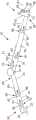
图1是在一个实施例中使用的带有末端执行器的臂的示意性侧视图;Figure 1 is a schematic side view of an arm with an end effector used in one embodiment;
图2是图1中所示的臂的一部分的示意性侧视细节图;Figure 2 is a schematic side detail view of a portion of the arm shown in Figure 1;
图3是穿过图1中所示的臂的一部分的示意性横截面图;Figure 3 is a schematic cross-sectional view through a portion of the arm shown in Figure 1;
图4是根据一个实施例的传送机的一部分的细节的示意性侧视图;Figure 4 is a schematic side view of a detail of a portion of a conveyor according to one embodiment;
图5A是在传送机中使用的转台的透视图,其中转台穿梭机径向向外延伸;Figure 5A is a perspective view of a turntable used in a conveyor with the turntable shuttle extending radially outward;
图5B是图5A的转台的透视图,其中转台穿梭机沿着转台的轴向延伸范围延伸;Figure 5B is a perspective view of the turntable of Figure 5A, wherein the turntable shuttle extends along the axial extent of the turntable;
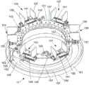
图6是传送机中使用的多隔间转盘的透视图,Figure 6 is a perspective view of a multi-compartment carousel used in a conveyor,
图7至图14是一系列侧视图,示出了运行中的传送机的一部分的细节;Figures 7 to 14 are a series of side views showing details of a portion of the conveyor in operation;
图15是被示出了将物体放置到多隔间转盘上的搬运机器人的一个示例的透视图;而且,15 is a perspective view of an example of a handling robot shown placing objects onto a multi-compartment carousel; and,
图16是自动砌砖机器的侧视图,该自动砌砖机器具有用于将砖块传输到末端执行器的传送机。Figure 16 is a side view of an automated bricklaying machine with a conveyor for transferring bricks to an end effector.
优选实施方案的详述DETAILED DESCRIPTION OF THE PREFERRED EMBODIMENT
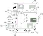
该实施例是一种传送系统,其具有用于在供应线中使用的多隔间转盘11,在该供应线中,零件被从卸载和初始加工转移到附加制造过程中进行进一步加工。转盘11的所设想用于的特定应用是在自动砌砖机器中。转盘11被置于对砖块进行卸载和切割以及碾磨操作之间的位置,并且被运输到末端执行器15,在那里砖块被胶粘并铺设。This embodiment is a transfer system with a
自动砌砖机器人机器300的示例在图16中示出。砌砖机器具有:卡车形式的底座310,该底座310具有支撑在竖直偏转轴线上的塔(或转台)25形式的转台;和铰接臂,该铰接臂具有绕水平俯仰轴线支撑在塔25上的伸缩吊杆17,该臂可以围绕该水平俯仰轴线上升或下降。吊杆17具有伸缩杆和末端执行器15,伸缩杆围绕水平枢转轴线安装在吊杆17的端部,末端执行器15为粘合剂涂敷及砌砖头43的形式,安装到杆的远端。砖块被储存在卡车的储存区域中,并且传送机将砖块从卡车13经由转盘、转台和臂传送到粘合剂涂敷及砌砖头43。An example of an automated bricklaying
砖块在吊杆内运输,吊杆为可折合伸缩臂的形式,总体上用17表示。吊杆17具有伸缩吊杆元件19和21,伸缩吊杆元件19和21由伺服马达驱动以受控的方式相对于彼此伸缩。吊杆元件19的近端23围绕水平轴线27安装到转台25,允许吊杆17在竖直平面内上升和下降。Bricks are transported in the boom, which is in the form of a foldable telescopic arm, generally represented by 17 .
在吊杆元件21的远端29,包括伸缩杆元件31、33和35的伸缩杆组件围绕水平轴线37安装。伸缩杆元件31、33和35可以由伺服马达驱动以受控方式相对于彼此伸缩。吊杆和末端执行器的实施例的进一步细节在图1中示出。在杆元件35的远端39处,粘合剂涂敷及砌砖头43围绕水平轴线41安装以进行枢转运动。粘合剂涂敷及砌砖头43具有连接到其上的末端执行器15。末端执行器15具有底座45、机器人臂47和用于接收夹取和放置砖块13的夹取器49。底座45可以使机器人臂47围绕水平轴线51旋转,并且该臂既可以围绕水平轴线53枢转,又可以在位于底座45中的托架中沿着臂的轴向长度滑动,以便实现对夹取器49的精确定位。粘合剂涂敷及砌砖头43在致动器的控制下绕其轴线41旋转,被控制成使得底座45的轴线51保持水平。At the
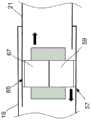
伸缩吊杆元件19具有沿着吊杆元件19的底部延伸的轨道55。该轨道支撑穿梭机57,该穿梭机57具有用于夹取砖块61的夹取器59。穿梭机57可以穿过轨道55的长度,直到穿梭机57到达吊杆元件21。伸缩吊杆元件21也具有轨道63,该轨道63沿吊杆元件21的顶部延伸。轨道63支撑穿梭机65,该穿梭机65具有用于夹取砖块69的夹取器67。穿梭机65可以穿过轨道63的整个长度,直到穿梭机65到达杆元件31。The
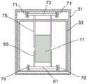
伸缩杆元件31具有沿着杆元件31的顶部延伸的轨道71。轨道71支撑具有夹取器75的穿梭机73,夹取器75用于夹取砖块77。穿梭机73可以穿过轨道71的长度,直到穿梭机73到达杆元件33。伸缩杆元件33具有沿着杆元件33的底部延伸的轨道79。轨道79支撑穿梭机81,该穿梭机81具有用于夹取砖块85的夹取器83。穿梭机81可以穿过轨道79的长度,直到穿梭机81到达杆元件35。伸缩杆元件35具有沿着杆元件35的顶部延伸的轨道87。轨道87支撑穿梭机89,该穿梭机89带有用于夹取砖块93的夹取器91。穿梭机89可以穿过轨道87的长度,直到穿梭机89到达粘合剂涂敷及砌砖头43。The
穿梭机可以在其各自的吊杆或杆元件内沿着轨道移动,以沿着可折合伸缩臂移动砖块。如图2所示,在伸缩元件会合的地方,穿梭机可以会合使它们的夹取器重合,以允许砖块从一个穿梭机传递到下一个穿梭机。以这种方式,砖块从一个穿梭机传递到另一个穿梭机,以沿着可折合伸缩臂17将物体移出。The shuttles can move along rails within their respective boom or rod elements to move the bricks along the collapsible telescoping arms. As shown in Figure 2, where the telescoping elements meet, the shuttles can come together to coincide their grippers to allow bricks to be passed from one shuttle to the next. In this way, the bricks are passed from one shuttle to the other to remove objects along the
转台25安装到底座95,并可绕竖直轴线97旋转,从而可折合伸缩臂17可绕底座95径向扫过。The
转台25具有带有夹取器103的穿梭机101,夹取器103夹取砖块,并安装在竖直延伸的轨道104上,这样物体可以从它被置于转台25底部的位置沿转台25向上呈送到安装在枢转支架107上的夹取器105,枢转支架107也绕水平轴线27旋转。枢转夹取器105可以绕水平轴线27旋转,以与转台穿梭机夹取器103对齐,以接收来自转台穿梭机夹取器103的砖块,并且旋转以与吊杆穿梭机夹取器59对齐,进而将砖块从转台25传输到吊杆元件19。The
当转台25相对于底座旋转时,带有其转台穿梭机101的竖直延伸轨道104随之旋转。转盘11被定位成围绕转台25的底部113延伸,并且可控制地围绕转台25旋转,使得砖块可以通过搬运机器人夹取器115(如图15所示)放置于转盘11上,并且转盘11可以被旋转,使得砖块与转台穿梭机轨道104对齐,以将砖块呈送到转台穿梭机夹取器103。转台穿梭机101上的夹取器103绕由伺服马达119驱动的枢转毂117形成的横向轴线旋转,因此夹取器103可以水平伸过转盘11,并向上转动到竖直位置(如103’所示),从而在转台穿梭机已经沿着竖直延伸的轨道104穿过转台25之后,夹取器103可以将砖块呈送给枢转夹取器105。图15示出了搬运机器人200的一个示例性示例,其中带有携带着砖块230的夹取器115的机器人臂210伸到转盘11的上方,并将砖块放置到一个物体隔间中。As the
参考图6,转盘11被更详细地示出。转盘11具有围绕转台25旋转的环形框架121。环形框架121具有六个物体隔间123、125、127、129、131和133。每个物体隔间支撑由夹爪(jaw)135和137形成的夹取器,该夹取器被承载在支承杆139和导螺杆141上。夹爪135和137具有精密的螺纹或导螺母,以匹配导螺杆141上的螺纹。具有齿形轮的马达143驱动齿形带145,以驱动固定到导螺杆141的齿形轮。马达143在一个方向上的旋转使两个夹爪135和137彼此相背运动,而在另一个方向上的旋转使夹爪135和137彼此相对运动。当夹爪135和137移动时,夹爪135和137之间的中心平面保持在恒定位置,使得任何砖块都将相对于夹爪135和137居中定位,尽管砖块宽度可能不同。Referring to Figure 6, the
底座95支撑安装在框架148上的环形引导件147。环形引导件147支撑多个滚轴(roller),滚轴进而支撑环形框架121,环形框架121形成回转轴承,该回转轴承因此能够绕竖直轴线97旋转。环形框架121通过伺服马达和齿轮箱153绕竖直轴线97旋转,伺服马达和齿轮箱153驱动小齿轮155,小齿轮155与固定在环形框架121下面的环形齿轮接合。伺服马达和齿轮箱153安装到框架148。缆线链157从框架148延伸,并由圆形金属片缆线链引导件159限制,该引导件159具有周壁161以容纳缆线链157。缆线链157延伸到缆线导管163,缆线导管163向目标隔间123、125、127、129、131和133上的马达143提供电力和控制信号。缆线链157和缆线导管163随着环形框架121旋转。
转盘11可以旋转以将任何物体隔间123、125、127、129、131和133呈送给搬运机器人夹取器115可以放置砖块的位置,并且将预定的物体隔间123、125、127、129、131或133旋转到放下位置,在该放下位置,转台25上的穿梭机101的夹取器103可以向下旋转以拾起砖块,沿转台上升,并且向上旋转以使砖块沿转台竖直对准。The
参考图5A和5B,竖直延伸的轨道104由两个平行的间隔开的线性支承导轨形成。线性支承导轨分别支撑四个支承车,这些支承车支撑转台穿梭机101,转台穿梭机101又支撑夹取器103。从图5A中可以看出,转台穿梭机支撑着具有带齿小齿轮的伺服马达165,带齿小齿轮与齿条167接合,以沿着竖直延伸的轨道104驱动转台穿梭机101。Referring to Figures 5A and 5B, the vertically extending
夹取器103位于沿着轨道171运行的支承车169上,由驱动驱动带173的伺服马达驱动,驱动带173驱动导螺杆打开和关闭夹取器103,以夹取和释放砖块。
类似地,在枢转支架107中,定位有驱动齿形带177的伺服马达175,齿形带177驱动导螺杆以移动构成夹取器105的夹爪。夹取器也安装在支承车上,以沿轨道进行直线移动。为了简洁起见,夹取器105被称为枢转夹取器,因为它们安装在枢转支架107上。枢转支架107通过驱动齿形带181的伺服马达179绕轴线27旋转,齿形带181驱动带有内部减速齿轮的毂183。Similarly, in the
支架191从转台25的一侧193横向向外延伸,而另一个类似的支架195从转台的另一侧197横向向外延伸。支架191和195上的螺栓199被布置成使其轴向延伸与竖直轴线97同轴,并固定到转盘11的环形引导件147上。因此,当转台绕竖直轴线97旋转时,转盘11随之旋转,但是转盘11可以通过对伺服马达和齿轮箱153的操作而相对于转台25独立地旋转。A
转台25支撑具有孔213的凸耳209,孔213具有水平轴线214,孔接收紧固件以连接液压动力缸(未示出)的端部,从而控制吊杆元件19的姿态。转台25支撑夹具板(clevisplates)210、211,夹具板210、211具有带有水平轴线27的孔212,吊杆元件19的近端23围绕该孔被附接,以进行枢转运动。The
参照图4和图7至图14,一系列视图图示了用于建造建筑物的砖块经过转盘11、转台25进入吊杆元件19的近端23中的传送。在图4中,搬运机器人夹取器115保持砖块,并且一次一个地将这样的砖块水平放置在物体隔间123、125、127、129、131和133之一中。在此例中,搬运机器人夹取器115和砖块悬空在物体隔间131上方。转盘11被旋转以将物体隔间123、125、127、129、131和133中的任何一个呈送给转台穿梭机101上的夹取器103。参考图7,转盘被旋转以将物体隔间123呈送在转台穿梭机101上的夹取器103可以接近该物体隔间的位置。如图8所示,转台穿梭机101沿着转台25下降,直到它的夹取器103到达一预定位置,在该位置夹取器103可以夹紧砖块。夹取器103夹取砖块,并且物体隔间123的夹爪135和137释放砖块。Referring to FIGS. 4 and 7 to 14 , a series of views illustrate the transfer of bricks for building a building through the
如图9所示,转台穿梭机101的夹取器103绕枢转毂117旋转,以便竖直地呈送砖块。如图10所示,转台穿梭机101沿转台25上升,直到砖块到达靠近枢转支架107的夹取器105的预定位置。在该位置,夹取器105将在夹取器103释放砖块之前夹取砖块。如图11和12所示,枢转支架107绕水平轴线27旋转,直到砖块与吊杆19的轴向延伸对齐。在此过程中,穿梭机57在吊杆元件19内在其轨道上移动,直到其夹取器59到达预定位置,在该预定位置,夹取器59在夹取器105释放砖块之前夹取砖块,随后穿梭机沿着吊杆19移动砖块。如图13和14所示,在枢转支架107旋转离开吊杆19之前,夹取器105绕水平轴线27旋转到水平位置。转盘然后可以旋转,以将另一个物体隔间呈送给转台穿梭机,并且重复该过程。As shown in Figure 9, the
转盘11的物体隔间123、125、127、129、131和133用作可以以两种方式操作的缓冲区。在砌砖操作运行平稳的情况下,物体隔间可能装满了砖块。以这种方式,在砖块上进行一定的操作,在将砖块放置在物体隔间之前需要花费一些时间来进行,例如切割操作或特形铣操作,或者尤其是切割和特形铣操作两者,砌砖可以用已经装载到转盘上的备料持续进行,直到转盘的装载能够跟上才耗尽该备料。如果进行了切割操作,切割成一定长度的砖块和边角料都可以储存在单独的物体隔间中,边角料被保存,直到需要该边角料长度的砖块时为止。The object compartments 123, 125, 127, 129, 131 and 133 of the
另一种操作模式是通过粘合剂涂敷和砌砖头来放置砖块有潜在麻烦的情况。这可能是砖块被加工成在搬运时有破损风险的构型的情况。在这种情况下,物体隔间是空运行的,并且沿着吊杆和杆行进的任何砖块,在被存储在转盘11的物体隔间123、125、127、129、131和133中之前,可以被倒出来并返回到塔中,同时替换砖块被加工并放置在转盘11的物体隔间123、125、127、129、131和133中的一个中,并且如所述的被传输到吊杆并传输出来到达砌砖和粘合剂涂敷头。Another mode of operation is where brick placement is potentially troublesome by adhesive application and bricklaying. This may be the case where the bricks are processed into configurations that risk breakage when handled. In this case, the object compartments are run dry, and any bricks traveling along the booms and rods, before being stored in the object compartments 123, 125, 127, 129, 131 and 133 of the
因此,转盘允许储存砖块边角料以备后用,并提供缓冲区以提供一定的缓冲容量,允许需要不同时间的不同的过程。缓冲区可以吸收以前流程中的备料,并立即为下一个流程提供备料。Thus, the turntable allows the storage of brick scraps for later use and provides a buffer zone to provide a certain buffer capacity, allowing different processes requiring different times. The buffer zone can absorb the stock from the previous process and make it available for the next process immediately.
转盘还能够从多个并行的先前过程中以任意顺序接收备料,并且通过选择物体隔间,备料可以按照下游工艺所需的顺序排序。The carousel is also capable of receiving stock in any order from multiple parallel prior processes, and by selecting object compartments, the stock can be sequenced in the order required by the downstream process.
在本说明书和随附的权利要求中,除非上下文另有要求,否则文字“包括(comprise)”以及诸如“包括(comprises)”或“包括(comprising)”之类的变体将被理解为暗示包括所述整体或整体或步骤的组,但不排除任何其他整体或整体的组。In this specification and the appended claims, unless the context requires otherwise, the word "comprise" and variations such as "comprises" or "comprising" will be read to imply Said integers or groups of integers or steps are included but not excluded any other integers or groups of integers.
本领域技术人员将了解,许多变化和修改将变得明显。对本领域技术人员而言变得明显的所有这些变化和修改都应被认为落在上述本发明中广泛呈现的精神和范畴内。It will be understood by those skilled in the art that many changes and modifications will become apparent. All such changes and modifications which become apparent to those skilled in the art are considered to be within the spirit and scope of the invention broadly presented above.
Claims (29)
Translated fromChineseApplications Claiming Priority (3)
| Application Number | Priority Date | Filing Date | Title |
|---|---|---|---|
| AU2017904110 | 2017-10-11 | ||
| AU2017904110AAU2017904110A0 (en) | 2017-10-11 | Carousel with Object Locating Bays for Buffering in a conveying operation, and Carousel with Object Locating Bays and a Turret and Boom associated therewith | |
| PCT/AU2018/051102WO2019071313A1 (en) | 2017-10-11 | 2018-10-11 | Machine for conveying objects and multi-bay carousel for use therewith |
Publications (2)
| Publication Number | Publication Date |
|---|---|
| CN111212799A CN111212799A (en) | 2020-05-29 |
| CN111212799Btrue CN111212799B (en) | 2023-04-14 |
Family
ID=66100144
Family Applications (1)
| Application Number | Title | Priority Date | Filing Date |
|---|---|---|---|
| CN201880066756.2AActiveCN111212799B (en) | 2017-10-11 | 2018-10-11 | Machine for conveying objects and multi-compartment carousel for use therewith |
Country Status (7)
| Country | Link |
|---|---|
| US (1) | US11401115B2 (en) |
| EP (1) | EP3694793B1 (en) |
| CN (1) | CN111212799B (en) |
| AU (1) | AU2018348785B2 (en) |
| ES (1) | ES2971624T3 (en) |
| SA (1) | SA520411751B1 (en) |
| WO (1) | WO2019071313A1 (en) |
Families Citing this family (15)
| Publication number | Priority date | Publication date | Assignee | Title |
|---|---|---|---|---|
| ES2899585T3 (en) | 2016-07-15 | 2022-03-14 | Fastbrick Ip Pty Ltd | Material transport boom |
| ES2899284T3 (en) | 2016-07-15 | 2022-03-10 | Fastbrick Ip Pty Ltd | Vehicle incorporating a brick laying machine |
| WO2019006511A1 (en) | 2017-07-05 | 2019-01-10 | Fastbrick Ip Pty Ltd | Real time position and orientation tracker |
| CN111213098B (en) | 2017-08-17 | 2024-03-15 | 快砖知识产权私人有限公司 | Communication systems for interactive systems |
| WO2019033170A1 (en) | 2017-08-17 | 2019-02-21 | Fastbrick Ip Pty Ltd | Laser tracker with improved roll angle measurement |
| CN111212799B (en) | 2017-10-11 | 2023-04-14 | 快砖知识产权私人有限公司 | Machine for conveying objects and multi-compartment carousel for use therewith |
| CN112689552A (en) | 2018-07-16 | 2021-04-20 | 快砖知识产权私人有限公司 | Active damping system |
| US12214500B2 (en) | 2018-07-16 | 2025-02-04 | Fastbrick Ip Pty Ltd | Backup tracking for an interaction system |
| US11951616B2 (en) | 2018-11-14 | 2024-04-09 | Fastbrick Ip Pty Ltd | Position and orientation tracking system |
| US12385265B2 (en) | 2020-04-22 | 2025-08-12 | Fastbrick Ip Pty Ltd | Block transfer apparatus and improved clamping assembly for use therewith |
| EP4179172A4 (en) | 2020-07-08 | 2024-08-07 | Fastbrick IP Pty Ltd | ADHESIVE APPLICATION SYSTEM |
| CN112047080A (en)* | 2020-08-29 | 2020-12-08 | 河南交通职业技术学院 | Rotary disc type basalt fiber automatic feeding device |
| ES1260666Y1 (en)* | 2020-11-23 | 2021-12-28 | Posimat Sa | MACHINE FOR ORIENTATION AND ALIGNMENT OF BULK FED ARTICLES |
| CN113882695B (en)* | 2021-10-26 | 2023-03-24 | 中国建筑第八工程局有限公司 | Special-shaped hyperboloid single-layer latticed shell steel structure construction device and construction method |
| AU2023370523A1 (en)* | 2022-10-26 | 2025-05-08 | Fastbrick Ip Pty Ltd | Transfer robot for handling blocks |
Family Cites Families (430)
| Publication number | Priority date | Publication date | Assignee | Title |
|---|---|---|---|---|
| GB125079A (en) | 1916-03-25 | 1919-12-18 | Maximilian Charles Schweinert | Improvements in and relating to Tyre Pressure Gauges. |
| GB119331A (en) | 1917-11-13 | 1918-10-03 | Stewart Kaye | Improvements in and relating to Machines for Erecting Walls of Bricks and the like. |
| US1633192A (en) | 1926-03-10 | 1927-06-21 | George D Reagan | Reenforced hollow fracturable building unit |
| US1829435A (en) | 1929-09-21 | 1931-10-27 | Utility Block Inc | Hollow building block |
| GB673472A (en) | 1947-09-16 | 1952-06-04 | Emin Balin | Improvements in or relating to building slabs |
| GB682010A (en) | 1950-02-22 | 1952-11-05 | Stanislaw Sulich | An improved hollow building brick or block |
| GB839253A (en) | 1956-08-07 | 1960-06-29 | Joseph Burns | Improvements relating to building blocks |
| US3292310A (en) | 1964-02-20 | 1966-12-20 | Internat Diamond Products Ltd | Apparatus for grinding bricks or the like |
| US3438171A (en) | 1966-10-24 | 1969-04-15 | Demarest Machine Inc | Bricklaying machine |
| CH536915A (en) | 1970-10-06 | 1973-05-15 | Lingl Hans | Method and device for the prefabrication of wall parts from building elements that can be connected by means of mortar, in particular block bricks |
| USRE28305E (en) | 1972-05-15 | 1975-01-21 | Automated bricklaying device | |
| US3757484A (en) | 1972-05-15 | 1973-09-11 | Combustion Enginc | Automated bricklaying device |
| US3930929A (en) | 1972-11-03 | 1976-01-06 | Lingl Corporation | Apparatus to construct wall panels having openings for doors and windows |
| CH558860A (en) | 1973-05-23 | 1975-02-14 | Zuercher Ziegeleien | DIVISIBLE BRICK, IN PARTICULAR BRICK IN SPECIAL QUALITY. |
| GB1465068A (en) | 1973-09-20 | 1977-02-23 | Laing & Son Ltd John | Apparatus for the positioning of elements more particularly building elements |
| DE2605970C3 (en) | 1975-02-17 | 1978-07-06 | Cervinter Ab, Malmoe (Schweden) | Device to facilitate the transport of material and the construction of walls made of molded stone, which are closed along their circumference, in particular the lining of converters, metallurgical furnaces, such as blast furnaces, holding devices or the like |
| FR2345367A1 (en) | 1976-03-22 | 1977-10-21 | Sapic | CARROUSEL WITH HORIZONTAL CLOSED CIRCUIT, INCLUDING SEVERAL ARMS JOINTLY WITH A VERTICAL AXIS ROTATING DRUM |
| US4245451A (en) | 1976-10-18 | 1981-01-20 | Taylor Smith Ernest J | Automatic method and apparatus for laying block units |
| US4106259A (en) | 1976-10-18 | 1978-08-15 | Taylor Smith Ernest J | Automatic apparatus for laying block units |
| SE418012B (en) | 1977-10-31 | 1981-04-27 | Cervinter Ab | WORK-EASY APPARATUS FOR TRANSPORTING BUILDING MATERIAL TO A WORKPLACE FROM A HIGHER TO A LOWER LEVEL, SPECIFICALLY DURING CONVERSION INFO |
| FR2524522B1 (en) | 1982-03-30 | 1985-07-19 | Ing Coordination Const | MODULAR HOLLOW CONSTRUCTION BLOCK |
| US4523100A (en) | 1982-08-11 | 1985-06-11 | R & D Associates | Optical vernier positioning for robot arm |
| DE3430915A1 (en) | 1984-08-22 | 1986-03-06 | Helmut Dipl.-Ing. 5020 Frechen Kober | Method and apparatus for producing a masonry structure from standard blocks and mortar or adhesive with the aid of industrial robots |
| DE3670872D1 (en) | 1985-01-24 | 1990-06-07 | Yannick Cruaud | BLOCK AND RELATED CONNECTOR. |
| LU86114A1 (en) | 1985-10-10 | 1987-06-02 | Wurth Paul Sa | INSTALLATION FOR BRIQUETTING THE INTERIOR WALL OF AN ENCLOSURE |
| US4852237A (en) | 1985-11-09 | 1989-08-01 | Kuka | Method and apparatus for mounting windshields on vehicles |
| LU86188A1 (en) | 1985-12-03 | 1987-07-24 | Wurth Paul Sa | AUTOMATIC OBJECT HANDLER AND ROBOT PROVIDED WITH SUCH A GRAPPLE |
| LU86272A1 (en) | 1986-01-28 | 1987-09-03 | Wurth Paul Sa | AUTOMATED INSTALLATION FOR BRIQUETTING THE INTERIOR WALL OF A SPEAKER |
| US4714339B2 (en) | 1986-02-28 | 2000-05-23 | Us Commerce | Three and five axis laser tracking systems |
| LU86382A1 (en) | 1986-04-01 | 1987-12-07 | Wurth Paul Sa | INSTALLATION FOR BRIQUETTING THE INTERIOR WALL OF AN ENCLOSURE |
| CH673498A5 (en) | 1986-08-27 | 1990-03-15 | Thomas Albert Pfister | Automatic brick laying system using programme-controlled robot - uses gripper to transfer bricks with simultaneous feed of bedding mortar |
| JPH07432Y2 (en)* | 1986-10-20 | 1995-01-11 | 北海製罐株式会社 | Can body transport device |
| JPS646719A (en) | 1987-06-26 | 1989-01-11 | Nec Corp | Robot hand position controller |
| US4790651A (en) | 1987-09-30 | 1988-12-13 | Chesapeake Laser Systems, Inc. | Tracking laser interferometer |
| LU87054A1 (en) | 1987-11-30 | 1989-06-14 | Wurth Paul Sa | INSTALLATION FOR BRIQUETTING THE INTERIOR WALL OF AN ENCLOSURE |
| NO164946C (en) | 1988-04-12 | 1990-11-28 | Metronor As | OPTO-ELECTRONIC SYSTEM FOR EXACTLY MEASURING A FLAT GEOMETRY. |
| US5080415A (en) | 1988-04-22 | 1992-01-14 | Beckman Instruments, Inc. | Robot gripper having auxiliary degree of freedom |
| DE3814810A1 (en) | 1988-05-02 | 1989-11-16 | Bodenseewerk Geraetetech | ACTUATOR FOR ADJUSTING A ROTATING ELEMENT |
| GB8815328D0 (en) | 1988-06-28 | 1988-08-03 | Shell Int Research | Process for reduction of carbonyl compounds |
| US4945493A (en) | 1988-09-26 | 1990-07-31 | Ford Motor Company | Method and system for correcting a robot path |
| LU87381A1 (en)* | 1988-11-09 | 1990-06-12 | Wurth Paul Sa | AUTOMATED INSTALLATION FOR LAYING A MASONRY ON A WALL |
| US4952772A (en) | 1988-11-16 | 1990-08-28 | Westinghouse Electric Corp. | Automatic seam tracker and real time error cumulative control system for an industrial robot |
| US4969789A (en) | 1988-12-16 | 1990-11-13 | Searle Gregory P | Machine for handling modular building components |
| JP2786225B2 (en) | 1989-02-01 | 1998-08-13 | 株式会社日立製作所 | Industrial robot control method and apparatus |
| US5044844A (en) | 1989-11-30 | 1991-09-03 | Furmanite Australia Pty. Ltd. | Machining apparatus |
| DE4014615A1 (en) | 1990-05-07 | 1991-11-14 | Anliker Hedwig | MACHINE MACHINE PRODUCTION PLANT |
| US5049797A (en) | 1990-07-02 | 1991-09-17 | Utah State University Foundation | Device and method for control of flexible link robot manipulators |
| AU645640B2 (en) | 1990-12-20 | 1994-01-20 | Self Levelling Machines Pty. Ltd. | Machining apparatus |
| DE4101402A1 (en) | 1991-01-18 | 1992-07-23 | Harmony Holdings Ltd | DEVICE AND METHOD FOR THE PRODUCTION OF UPRIGHT WALL PANELS FROM WALL STONES |
| DE4207384A1 (en) | 1992-03-09 | 1993-09-16 | Elmar Pinkhaus | Mechanical handling robot for use in construction industry - has gripper for bricks and blocks at end of articulated arm programmed to produce wall construction |
| US5737500A (en) | 1992-03-11 | 1998-04-07 | California Institute Of Technology | Mobile dexterous siren degree of freedom robot arm with real-time control system |
| US5321353A (en) | 1992-05-13 | 1994-06-14 | Storage Technolgy Corporation | System and method for precisely positioning a robotic tool |
| JP2769947B2 (en) | 1992-05-15 | 1998-06-25 | 株式会社椿本チエイン | Manipulator position / posture control method |
| US5527145A (en) | 1992-06-03 | 1996-06-18 | Duncan; Joseph C. | Mortaring made easier |
| LU88144A1 (en) | 1992-07-07 | 1994-04-01 | Wurth Paul Sa | Installation for lining an interior wall of an enclosure with brick masonry |
| US5284000A (en) | 1992-11-30 | 1994-02-08 | Redwall Engineering Corp. | Automating bricklaying |
| FR2700532B1 (en) | 1993-01-19 | 1995-03-03 | Potain Sa | Method of hybrid position / force control for manipulator robot. |
| US5497061A (en) | 1993-03-31 | 1996-03-05 | Hitachi, Ltd. | Method of controlling robot's compliance |
| US5413454A (en) | 1993-07-09 | 1995-05-09 | Movsesian; Peter | Mobile robotic arm |
| JP2970342B2 (en) | 1993-10-06 | 1999-11-02 | 株式会社日立製作所 | Library device |
| US5403140A (en) | 1993-10-13 | 1995-04-04 | Storage Technology Corporation | Dynamic sweeping mechanism for a line scan camera |
| US5420489A (en) | 1993-11-12 | 1995-05-30 | Rockwell International Corporation | Robotic end-effector with active system compliance and micro-positioning capability |
| IT1264301B1 (en)* | 1993-12-24 | 1996-09-23 | Ima Spa | HIGH PRODUCTION AUTOMATIC MACHINE FOR FILLING AND CLOSING BOTTLES OR OTHER CONTAINERS. |
| DE4409829C2 (en) | 1994-03-22 | 1996-08-22 | Manfred Kobler | Device and method for the production of structures using components made of brick and / or formwork |
| DE19509809A1 (en) | 1994-03-22 | 1995-10-05 | Konrad Hofmann | Creation of wall sections out of brickwork |
| DE4417928A1 (en) | 1994-05-24 | 1995-11-30 | Lissmac Maschb & Diamantwerkz | Device for deploying building blocks |
| US5557397A (en) | 1994-09-21 | 1996-09-17 | Airborne Remote Mapping, Inc. | Aircraft-based topographical data collection and processing system |
| AT402085B (en) | 1995-07-03 | 1997-01-27 | Opferkuch Bau Gmbh | ROBOTS FOR BRICKING FOR A RISING MASONRY |
| NO301999B1 (en) | 1995-10-12 | 1998-01-05 | Metronor As | Combination of laser tracker and camera based coordinate measurement |
| DE19600006A1 (en) | 1996-01-02 | 1997-07-03 | Frey Kurt Dipl Ing Fh | Automatic brick laying wall-building machine |
| DE29601535U1 (en) | 1996-01-30 | 1997-05-28 | Wassmer, Paul, 79423 Heitersheim | Automatic walling device |
| DE19603234C2 (en) | 1996-01-30 | 2001-01-04 | Paul Wasmer | Device for automatic walls |
| US6285959B1 (en) | 1996-02-06 | 2001-09-04 | Perceptron, Inc. | Method and apparatus for calibrating a non-contact gauging sensor with respect to an external coordinate system |
| US6134507A (en) | 1996-02-06 | 2000-10-17 | Perceptron, Inc. | Method and apparatus for calibrating a non-contact gauging sensor with respect to an external coordinate system |
| US5988862A (en) | 1996-04-24 | 1999-11-23 | Cyra Technologies, Inc. | Integrated system for quickly and accurately imaging and modeling three dimensional objects |
| US6681145B1 (en) | 1996-06-06 | 2004-01-20 | The Boeing Company | Method for improving the accuracy of machines |
| CN1105297C (en) | 1996-08-16 | 2003-04-09 | K·C·刘 | Five-axis/six-axis laser measurement system and method for determining object position and rolling displacement |
| US5838882A (en) | 1996-10-31 | 1998-11-17 | Combustion Engineering, Inc. | Dynamic position tracking and control of robots |
| US6172754B1 (en) | 1997-03-24 | 2001-01-09 | Uteda-Dr. Niebuhr Gmbh | Measuring system using laser technique for three-dimensional objects |
| US6310644B1 (en) | 1997-03-26 | 2001-10-30 | 3Dm Devices Inc. | Camera theodolite system |
| DE19743717C2 (en) | 1997-10-02 | 1999-08-12 | Paul Wasmer | Automatic walling device |
| US6018923A (en) | 1997-12-16 | 2000-02-01 | Usg Interiors, Inc. | Transition clip for drywall suspension grid |
| US6101455A (en) | 1998-05-14 | 2000-08-08 | Davis; Michael S. | Automatic calibration of cameras and structured light sources |
| IT1303239B1 (en) | 1998-08-07 | 2000-11-02 | Brown & Sharpe Dea Spa | DEVICE AND METHOD FOR POSITIONING A MEASURING HEAD IN A THREE-DIMENSIONAL MEASURING MACHINE WITHOUT CONTACT. |
| DE19849720A1 (en) | 1998-10-28 | 2000-05-04 | Bosch Gmbh Robert | Precision positioning of component in assembly position in grip-feed system makes position correction using coarse and fine positioning devices |
| JP4612194B2 (en) | 1998-12-23 | 2011-01-12 | イメージ・ガイディッド・テクノロジーズ・インコーポレイテッド | Hybrid 3D probe tracked by multiple sensors |
| US6330503B1 (en) | 1999-02-22 | 2001-12-11 | Trimble Navigation Limited | Global positioning system controlled staking apparatus |
| US7800758B1 (en) | 1999-07-23 | 2010-09-21 | Faro Laser Trackers, Llc | Laser-based coordinate measuring device and laser-based method for measuring coordinates |
| US6213309B1 (en) | 1999-04-30 | 2001-04-10 | B & H Manufacturing Company, Inc. | Turret feed control apparatus for sorting and distributing articles in a process system |
| US6850946B1 (en) | 1999-05-26 | 2005-02-01 | Wireless Valley Communications, Inc. | Method and system for a building database manipulator |
| EP1192413B1 (en) | 1999-06-10 | 2004-12-01 | MPT Präzisionsteile GmbH Mittweida | Device for the contactless three-dimensional measurement of bodies and method for determining a co-ordinate system for measuring point co-ordinates |
| US6370837B1 (en) | 1999-08-04 | 2002-04-16 | Anthony B. Mcmahon | System for laying masonry blocks |
| US6166811A (en) | 1999-08-12 | 2000-12-26 | Perceptron, Inc. | Robot-based gauging system for determining three-dimensional measurement data |
| US6429016B1 (en) | 1999-10-01 | 2002-08-06 | Isis Pharmaceuticals, Inc. | System and method for sample positioning in a robotic system |
| DE29918341U1 (en) | 1999-10-18 | 2001-03-01 | Tassakos Charalambos | Device for determining the position of measuring points of a measuring object relative to a reference system |
| SE515374C2 (en) | 1999-10-29 | 2001-07-23 | Abb Flexible Automation As | Method and apparatus for determining an object's coordinates and orientation in a reference coordinate system |
| FR2805350B1 (en) | 2000-02-18 | 2003-07-11 | Scertab Soc Civ Ile D Etudes E | TELEMETRY EQUIPMENT FOR BI- OR THREE-DIMENSIONAL MAPPING OF A VOLUME |
| GB0008303D0 (en) | 2000-04-06 | 2000-05-24 | British Aerospace | Measurement system and method |
| SE0001312D0 (en) | 2000-04-10 | 2000-04-10 | Abb Ab | Industrial robot |
| KR20030026972A (en) | 2000-07-14 | 2003-04-03 | 록히드 마틴 코포레이션 | System and method for locating and positioning an ultrasonic signal generator for testing purposes |
| US6664529B2 (en) | 2000-07-19 | 2003-12-16 | Utah State University | 3D multispectral lidar |
| JP2004507742A (en) | 2000-08-25 | 2004-03-11 | ギガー,クルト | Method and apparatus for distance measurement |
| GB0022444D0 (en) | 2000-09-13 | 2000-11-01 | Bae Systems Plc | Positioning system and method |
| US6427122B1 (en) | 2000-12-23 | 2002-07-30 | American Gnc Corporation | Positioning and data integrating method and system thereof |
| CA2348212A1 (en) | 2001-05-24 | 2002-11-24 | Will Bauer | Automatic pan/tilt pointing device, luminaire follow-spot, and 6dof 3d position/orientation calculation information gathering system |
| GB0125079D0 (en) | 2001-10-18 | 2001-12-12 | Cimac Automation Ltd | Auto motion:robot guidance for manufacturing |
| US6873880B2 (en) | 2001-12-26 | 2005-03-29 | Lockheed Martin Corporation | Machine for performing machining operations on a workpiece and method of controlling same |
| AU2003223173A1 (en) | 2002-02-14 | 2003-09-04 | Faro Technologies, Inc. | Portable coordinate measurement machine with integrated line laser scanner |
| US6957496B2 (en) | 2002-02-14 | 2005-10-25 | Faro Technologies, Inc. | Method for improving measurement accuracy of a portable coordinate measurement machine |
| USRE42082E1 (en) | 2002-02-14 | 2011-02-01 | Faro Technologies, Inc. | Method and apparatus for improving measurement accuracy of a portable coordinate measurement machine |
| US7246030B2 (en) | 2002-02-14 | 2007-07-17 | Faro Technologies, Inc. | Portable coordinate measurement machine with integrated line laser scanner |
| US7519493B2 (en) | 2002-02-14 | 2009-04-14 | Faro Technologies, Inc. | Portable coordinate measurement machine with integrated line laser scanner |
| US7881896B2 (en) | 2002-02-14 | 2011-02-01 | Faro Technologies, Inc. | Portable coordinate measurement machine with integrated line laser scanner |
| US6917893B2 (en) | 2002-03-14 | 2005-07-12 | Activmedia Robotics, Llc | Spatial data collection apparatus and method |
| US20030206285A1 (en) | 2002-05-06 | 2003-11-06 | Automated Precision, Inc. | Nine dimensional laser tracking system and method |
| US6868847B2 (en) | 2002-06-17 | 2005-03-22 | Dieter Ainedter | Method and apparatus for producing wall panels |
| US7111437B2 (en) | 2002-06-17 | 2006-09-26 | Dieter Ainedter | Apparatus for making brick wall elements |
| DE10230021C1 (en) | 2002-07-04 | 2003-07-10 | Daimler Chrysler Ag | Method of cleaning motor vehicle body panel involves using contact cleaning head with manipulator having rough and fine positioning controls |
| GB0215557D0 (en) | 2002-07-05 | 2002-08-14 | Renishaw Plc | Laser calibration apparatus |
| NZ537962A (en) | 2002-07-31 | 2006-10-27 | Japan Science & Tech Agency | Method for planning construction of brick wall |
| US6741364B2 (en) | 2002-08-13 | 2004-05-25 | Harris Corporation | Apparatus for determining relative positioning of objects and related methods |
| US7230689B2 (en) | 2002-08-26 | 2007-06-12 | Lau Kam C | Multi-dimensional measuring system |
| FI20021531L (en) | 2002-08-28 | 2004-02-29 | U H Rakennus Oy | Masonry method |
| US6859729B2 (en) | 2002-10-21 | 2005-02-22 | Bae Systems Integrated Defense Solutions Inc. | Navigation of remote controlled vehicles |
| AU2003304436A1 (en) | 2002-12-13 | 2005-03-07 | Utah State University Research Foundation | A vehicle mounted system and method for capturing and processing physical data |
| JP3711105B2 (en) | 2002-12-20 | 2005-10-26 | ファナック株式会社 | 3D measuring device |
| US7153454B2 (en) | 2003-01-21 | 2006-12-26 | University Of Southern California | Multi-nozzle assembly for extrusion of wall |
| EP1447644A1 (en) | 2003-02-14 | 2004-08-18 | Metronor ASA | Measurement of spatial coordinates |
| US7107144B2 (en) | 2003-02-27 | 2006-09-12 | Spectra Research, Inc. | Non-intrusive traffic monitoring system |
| NL1022970C2 (en) | 2003-03-19 | 2004-09-21 | Essab B V | Device and method for manufacturing a structural part from building elements and adhesive material. |
| JP4294990B2 (en) | 2003-03-28 | 2009-07-15 | 三菱電機エンジニアリング株式会社 | Deformed article transfer device |
| CA2522097C (en) | 2003-04-28 | 2012-09-25 | Stephen James Crampton | Cmm arm with exoskeleton |
| US6704619B1 (en) | 2003-05-24 | 2004-03-09 | American Gnc Corporation | Method and system for universal guidance and control of automated machines |
| US7142981B2 (en) | 2003-08-05 | 2006-11-28 | The Boeing Company | Laser range finder closed-loop pointing technology of relative navigation, attitude determination, pointing and tracking for spacecraft rendezvous |
| WO2005014240A1 (en) | 2003-08-11 | 2005-02-17 | Mindready, Solutions Inc. | Micro-assembly and test station applied for the chip and bar tester application |
| US20050057745A1 (en) | 2003-09-17 | 2005-03-17 | Bontje Douglas A. | Measurement methods and apparatus |
| GB2391897B (en) | 2003-10-24 | 2004-06-23 | Paul Chisholm | Device for laying brick constructs |
| KR20060113930A (en) | 2003-12-30 | 2006-11-03 | 리포소닉스 인코포레이티드 | Systems and devices for the destruction of adipose tissue |
| US8337407B2 (en) | 2003-12-30 | 2012-12-25 | Liposonix, Inc. | Articulating arm for medical procedures |
| US7693325B2 (en) | 2004-01-14 | 2010-04-06 | Hexagon Metrology, Inc. | Transprojection of geometry data |
| EP2610417A1 (en) | 2004-01-20 | 2013-07-03 | University Of Southern California | Apparatus for automated construction comprising an extrusion nozzle and a robotic arm |
| US7551121B1 (en) | 2004-03-12 | 2009-06-23 | Oceanit Laboratories, Inc. | Multi-target-tracking optical sensor-array technology |
| US7130034B2 (en) | 2004-04-26 | 2006-10-31 | The Boeing Company | Metrology system and method for measuring five degrees-of-freedom for a point target |
| CN2730976Y (en) | 2004-07-13 | 2005-10-05 | 尹海法 | Easy cutting off hollow brick |
| US8029710B2 (en) | 2006-11-03 | 2011-10-04 | University Of Southern California | Gantry robotics system and related material transport for contour crafting |
| GB2422400A (en) | 2005-01-25 | 2006-07-26 | Edson Da Silva Rosa | Bricklaying apparatus |
| JP2006275910A (en) | 2005-03-30 | 2006-10-12 | Canon Inc | Position sensing device and position sensing method |
| FR2884845B1 (en) | 2005-04-21 | 2007-07-06 | Mathieu Leclercq | METHOD FOR CONSTRUCTING MACON WALLS AND DEVICE IMPLEMENTING SAID METHOD |
| JP4015161B2 (en) | 2005-06-13 | 2007-11-28 | 川崎重工業株式会社 | Industrial robot controller |
| EP2202482A1 (en) | 2005-06-23 | 2010-06-30 | Faro Technologies, Inc. | Apparatus and method for relocating an articulating-arm coordinate measuring machine |
| US20070024870A1 (en) | 2005-08-01 | 2007-02-01 | Girard Mark T | Apparatuses and methods for measuring head suspensions and head suspension assemblies |
| WO2007030026A1 (en) | 2005-09-09 | 2007-03-15 | Industrial Research Limited | A 3d scene scanner and a position and orientation system |
| JP2009521630A (en) | 2005-12-30 | 2009-06-04 | ゴールドウィング ノミニーズ ピーティーワイ リミテッド | Automatic brick laying system for building buildings with multiple bricks |
| CN2902981Y (en) | 2006-03-08 | 2007-05-23 | 张锦然 | Mechanical handling device of object stacking machine |
| EP2008120B1 (en) | 2006-04-20 | 2010-12-08 | Faro Technologies Inc. | Camera based six degree-of-freedom target measuring and target tracking device |
| WO2007124009A2 (en) | 2006-04-21 | 2007-11-01 | Faro Technologies, Inc. | Camera based six degree-of-freedom target measuring and target tracking device with rotatable mirror |
| DE602006007961D1 (en) | 2006-05-19 | 2009-09-03 | Abb As | Improved method for controlling a robot TCP |
| US7347311B2 (en) | 2006-06-07 | 2008-03-25 | Volvo Construction Equipment Ab | Folding mechanism for road machinery foldable conveyors |
| CN2923903Y (en) | 2006-06-19 | 2007-07-18 | 张健 | Building-brick robot |
| DE102006030130B3 (en) | 2006-06-28 | 2007-09-27 | Scansonic Gmbh | Workpiece machining method for, e.g., industrial robot, involves compensating deviation of determined actual-position from reference-movement path and deviation of determined actual-speed vector from measured reference-speed vector |
| US8060344B2 (en) | 2006-06-28 | 2011-11-15 | Sam Stathis | Method and system for automatically performing a study of a multidimensional space |
| IL177304A0 (en) | 2006-08-06 | 2007-07-04 | Raphael E Levy | A method and system for designating a target and generating target related action |
| JP5020585B2 (en) | 2006-09-27 | 2012-09-05 | 株式会社トプコン | Measuring system |
| AT503658B1 (en) | 2006-10-24 | 2007-12-15 | Kurz Josef Dipl Ing | Bricked prefabricated unit producing device for building block, has shifting mechanism with support having gripping device for detachable holding of block, by which prefabricated unit is producible by shifting block on conveying device |
| GB0622451D0 (en) | 2006-11-10 | 2006-12-20 | Intelligent Earth Ltd | Object position and orientation detection device |
| US8562274B2 (en)* | 2006-11-29 | 2013-10-22 | Pouch Pac Innovations, Llc | Load smart system for continuous loading of a pouch into a fill-seal machine |
| DE502007001288D1 (en) | 2007-01-02 | 2009-09-24 | Isis Sentronics Gmbh | Position detection system for contactless interferometric detection of the spatial position of a target object and thus equipped scanning system |
| US20080189046A1 (en) | 2007-02-02 | 2008-08-07 | O-Pen A/S | Optical tool with dynamic electromagnetic radiation and a system and method for determining the position and/or motion of an optical tool |
| EP2112470A4 (en) | 2007-02-12 | 2014-05-21 | Qifeng Yu | A photogrammetric method using folding optic path transfer for an invisible target of three-dimensional position and posture |
| US7639347B2 (en) | 2007-02-14 | 2009-12-29 | Leica Geosystems Ag | High-speed laser ranging system including a fiber laser |
| US9858712B2 (en) | 2007-04-09 | 2018-01-02 | Sam Stathis | System and method capable of navigating and/or mapping any multi-dimensional space |
| ES2296556B1 (en) | 2007-07-16 | 2009-08-18 | Pablo Germade Castiñeiras | AUTOMATIC MACHINE FOR THE FORMATION OF FACTORY WALLS BY ROWS. |
| CN100557169C (en) | 2007-07-26 | 2009-11-04 | 刘金前 | The machine of building a wall |
| US8036452B2 (en) | 2007-08-10 | 2011-10-11 | Leica Geosystems Ag | Method and measurement system for contactless coordinate measurement on an object surface |
| US9020240B2 (en) | 2007-08-10 | 2015-04-28 | Leica Geosystems Ag | Method and surveying system for noncontact coordinate measurement on an object surface |
| DE102007060263A1 (en) | 2007-08-16 | 2009-02-26 | Steinbichler Optotechnik Gmbh | Scanner for scanning e.g. teeth, in mouth of patient, has image optics arranged at distance to each other, where distance of optics and directions of optical axes are selected such that optics and axes are oriented to common area of tooth |
| AU2008291702A1 (en) | 2007-08-28 | 2009-03-05 | Goldwing Nominees Pty Ltd | System and method for precise real-time measurement of a target position and orientation relative to a base position, and control thereof |
| EP2053353A1 (en) | 2007-10-26 | 2009-04-29 | Leica Geosystems AG | Distance measuring method and corresponding device |
| TW200921042A (en) | 2007-11-07 | 2009-05-16 | Lite On Semiconductor Corp | 3D multi-degree of freedom detecting device and detecting method thereof |
| US8264697B2 (en) | 2007-11-27 | 2012-09-11 | Intelligrated Headquarters, Llc | Object detection device |
| US20100262008A1 (en) | 2007-12-13 | 2010-10-14 | Koninklijke Philips Electronics N.V. | Robotic ultrasound system with microadjustment and positioning control using feedback responsive to acquired image data |
| EP2075096A1 (en) | 2007-12-27 | 2009-07-01 | Leica Geosystems AG | Method and system for extremely precise positioning of at least one object in the end position of a space |
| CN201184054Y (en) | 2008-03-07 | 2009-01-21 | 杨晓龙 | Walling setting machine |
| NL1035335C2 (en) | 2008-04-23 | 2009-10-26 | Folierol V O F | Method and device for building terraced houses. |
| US9740922B2 (en) | 2008-04-24 | 2017-08-22 | Oblong Industries, Inc. | Adaptive tracking system for spatial input devices |
| FR2930472B1 (en) | 2008-04-24 | 2010-08-13 | Univ Havre | MANIPULATOR ROBOT AND ASSOCIATED CONTROL FOR FINAL POSITIONING OF TERMINAL END |
| EP2112465A1 (en) | 2008-04-24 | 2009-10-28 | Snap-on Equipment Srl a unico socio. | Parameter detection system for wheels |
| US7570371B1 (en) | 2008-05-12 | 2009-08-04 | Storm Thomas W | Apparatus and method for measuring volumes |
| US7967549B2 (en) | 2008-05-15 | 2011-06-28 | The Boeing Company | Robotic system including foldable robotic arm |
| WO2010020457A1 (en) | 2008-08-19 | 2010-02-25 | Delaval Holding Ab | Arrangement and method for controlling a movable robot arm |
| US8345926B2 (en) | 2008-08-22 | 2013-01-01 | Caterpillar Trimble Control Technologies Llc | Three dimensional scanning arrangement including dynamic updating |
| US8185240B2 (en) | 2008-08-29 | 2012-05-22 | Williams Robotics, Llc | Automated apparatus for constructing assemblies of building components |
| WO2010057169A2 (en) | 2008-11-17 | 2010-05-20 | Faro Technologies, Inc. | Device and method for measuring six degrees of freedom |
| US20100138185A1 (en) | 2008-12-02 | 2010-06-03 | Electronics And Telecommunications Research Institute | Device for three-dimensionally measuring block and system having the device |
| US9739595B2 (en) | 2008-12-11 | 2017-08-22 | Automated Precision Inc. | Multi-dimensional measuring system with measuring instrument having 360° angular working range |
| DE102008062509A1 (en) | 2008-12-16 | 2010-06-17 | Sms Siemag Aktiengesellschaft | Plant for lining an inner wall of an enclosure, in particular a converter, with a masonry of stones |
| US8803055B2 (en) | 2009-01-09 | 2014-08-12 | Automated Precision Inc. | Volumetric error compensation system with laser tracker and active target |
| RU85392U1 (en) | 2009-01-26 | 2009-08-10 | Государственное образовательное учреждение высшего профессионального образования "Южно-Российский Государственный Технический Университет (Новочеркасский Политехнический Институт) | FLEXIBLE ROBOT MANAGEMENT SYSTEM |
| US8082673B2 (en) | 2009-11-06 | 2011-12-27 | Hexagon Metrology Ab | Systems and methods for control and calibration of a CMM |
| DE102009018070A1 (en) | 2009-04-20 | 2010-10-21 | Robert Bosch Gmbh | Mobile work machine with a position control device of a working arm and method for position control of a working arm of a mobile machine |
| US8706297B2 (en) | 2009-06-18 | 2014-04-22 | Michael Todd Letsky | Method for establishing a desired area of confinement for an autonomous robot and autonomous robot implementing a control system for executing the same |
| EP2270425A1 (en) | 2009-07-03 | 2011-01-05 | Leica Geosystems AG | Coordinate measuring machine (CMM) and method of compensating errors in a CMM |
| US9255803B2 (en) | 2009-08-14 | 2016-02-09 | IPOZ Systems, LLC | Devices, program products and computer implemented methods for touchless metrology having virtual zero-velocity and position update |
| DE102009041734B4 (en) | 2009-09-16 | 2023-11-02 | Kuka Roboter Gmbh | Measuring a manipulator |
| DE102009042014A1 (en) | 2009-09-21 | 2011-03-24 | Dürr Systems GmbH | Handling device for moving e.g. scanner for handling articles, has manipulator accommodated at carrier structure of parallel geometry unit, where powered movement axes are provided for displacing carrier structure relative to base |
| CN101694130B (en) | 2009-10-19 | 2011-04-13 | 济南大学 | Wall-building robot |
| US8634950B2 (en) | 2009-12-14 | 2014-01-21 | Embraer S.A. | Automated positioning and alignment method and system for aircraft structures using robots |
| FI124179B (en) | 2009-12-22 | 2014-04-15 | Ibriq Oy | Method and apparatus for making a brick wall |
| BR112012015579A2 (en) | 2009-12-23 | 2016-03-22 | AEA Integration | system and method for design of automated building services |
| JP2011140077A (en) | 2010-01-06 | 2011-07-21 | Honda Motor Co Ltd | Processing system and processing method |
| US8677643B2 (en) | 2010-01-20 | 2014-03-25 | Faro Technologies, Inc. | Coordinate measurement machines with removable accessories |
| US9163922B2 (en) | 2010-01-20 | 2015-10-20 | Faro Technologies, Inc. | Coordinate measurement machine with distance meter and camera to determine dimensions within camera images |
| US8898919B2 (en) | 2010-01-20 | 2014-12-02 | Faro Technologies, Inc. | Coordinate measurement machine with distance meter used to establish frame of reference |
| US20130222816A1 (en) | 2010-01-20 | 2013-08-29 | Faro Technologies, Inc. | Coordinate measuring machine having an illuminated probe end and method of operation |
| US9607239B2 (en) | 2010-01-20 | 2017-03-28 | Faro Technologies, Inc. | Articulated arm coordinate measurement machine having a 2D camera and method of obtaining 3D representations |
| US8942940B2 (en) | 2010-01-20 | 2015-01-27 | Faro Technologies, Inc. | Portable articulated arm coordinate measuring machine and integrated electronic data processing system |
| US9879976B2 (en) | 2010-01-20 | 2018-01-30 | Faro Technologies, Inc. | Articulated arm coordinate measurement machine that uses a 2D camera to determine 3D coordinates of smoothly continuous edge features |
| US8875409B2 (en) | 2010-01-20 | 2014-11-04 | Faro Technologies, Inc. | Coordinate measurement machines with removable accessories |
| US8832954B2 (en) | 2010-01-20 | 2014-09-16 | Faro Technologies, Inc. | Coordinate measurement machines with removable accessories |
| DE102010007591A1 (en) | 2010-02-04 | 2011-08-04 | Bremer Werk für Montagesysteme GmbH, 28239 | Working device with robot on movable platform as well as working method |
| JP5508895B2 (en) | 2010-02-22 | 2014-06-04 | 本田技研工業株式会社 | Processing system and processing method |
| DE102010028383A1 (en)* | 2010-04-29 | 2011-11-03 | Krones Ag | Method for handing over an article |
| JP2013528795A (en) | 2010-05-04 | 2013-07-11 | クリアフォーム インコーポレイティッド | Target inspection using reference capacitance analysis sensor |
| US9033998B1 (en) | 2010-05-13 | 2015-05-19 | Titan Medical Inc. | Independent roll wrist mechanism |
| US9109877B2 (en) | 2010-05-21 | 2015-08-18 | Jonathan S. Thierman | Method and apparatus for dimensional measurement |
| US9248576B2 (en) | 2010-05-31 | 2016-02-02 | National Institute Of Advanced Industrial Science And Technology | Direct acting extensible and retractable arm mechanism, and robot arm provided with direct acting extensible and retractable arm mechanism |
| US9146315B2 (en) | 2010-07-26 | 2015-09-29 | Commonwealth Scientific And Industrial Research Organisation | Three dimensional scanning beam system and method |
| US8965571B2 (en) | 2010-08-12 | 2015-02-24 | Construction Robotics, Llc | Brick laying system |
| EP2433716A1 (en) | 2010-09-22 | 2012-03-28 | Hexagon Technology Center GmbH | Surface spraying device with a nozzle control mechanism and a corresponding method |
| CA2891008C (en) | 2010-09-28 | 2019-05-07 | Williams Robotics Llc | Automated apparatus for constructing assemblies of building components |
| US8868302B2 (en) | 2010-11-30 | 2014-10-21 | Caterpillar Inc. | System for autonomous path planning and machine control |
| DE102010061382B4 (en) | 2010-12-21 | 2019-02-14 | Sick Ag | Opto-electronic sensor and method for detection and distance determination of objects |
| US10168153B2 (en) | 2010-12-23 | 2019-01-01 | Trimble Inc. | Enhanced position measurement systems and methods |
| CN201972413U (en) | 2011-01-17 | 2011-09-14 | 淮安信息职业技术学院 | Automatic wall building machine |
| US8902408B2 (en) | 2011-02-14 | 2014-12-02 | Faro Technologies Inc. | Laser tracker used with six degree-of-freedom probe having separable spherical retroreflector |
| GB2503390B (en) | 2011-03-03 | 2014-10-29 | Faro Tech Inc | Target apparatus and method |
| EP2511656A1 (en) | 2011-04-14 | 2012-10-17 | Hexagon Technology Center GmbH | Measuring system for determining the 3D coordinates of an object surface |
| US9686532B2 (en) | 2011-04-15 | 2017-06-20 | Faro Technologies, Inc. | System and method of acquiring three-dimensional coordinates using multiple coordinate measurement devices |
| JP2014516409A (en) | 2011-04-15 | 2014-07-10 | ファロ テクノロジーズ インコーポレーテッド | Improved position detector for laser trackers. |
| US8825208B1 (en) | 2011-06-10 | 2014-09-02 | Richard Mark Benson | Automated construction machinery and method |
| US9279661B2 (en) | 2011-07-08 | 2016-03-08 | Canon Kabushiki Kaisha | Information processing apparatus and information processing method |
| US9437005B2 (en) | 2011-07-08 | 2016-09-06 | Canon Kabushiki Kaisha | Information processing apparatus and information processing method |
| CN202292752U (en) | 2011-07-13 | 2012-07-04 | 徐州海伦哲专用车辆股份有限公司 | Multifunctional high-lift operation mechanical arm |
| CN202248944U (en) | 2011-07-14 | 2012-05-30 | 魏晓峰 | Novel wall building equipment |
| BR112014005878A2 (en) | 2011-09-13 | 2020-10-27 | Osi Optoelectronics, Inc. | improved laser rangefinder sensor |
| US8996244B2 (en) | 2011-10-06 | 2015-03-31 | Harris Corporation | Improvised explosive device defeat system |
| DE102011084412A1 (en) | 2011-10-13 | 2013-04-18 | Kuka Roboter Gmbh | Robot control method |
| CN102359282B (en) | 2011-10-23 | 2014-04-02 | 陈永兴 | Wall building and painting device |
| US20130104407A1 (en) | 2011-10-26 | 2013-05-02 | Hexagon Technology Center Gmbh | Determining thread lead or pitch accurately |
| EP2602588A1 (en) | 2011-12-06 | 2013-06-12 | Hexagon Technology Center GmbH | Position and Orientation Determination in 6-DOF |
| GB2497537B (en) | 2011-12-13 | 2014-07-09 | Intelligent Building Processes Ltd | New building blocks,building systems and methods of building |
| US20140002608A1 (en) | 2011-12-28 | 2014-01-02 | Faro Technologies, Inc. | Line scanner using a low coherence light source |
| US20130286196A1 (en) | 2011-12-28 | 2013-10-31 | Faro Technologies, Inc. | Laser line probe that produces a line of light having a substantially even intensity distribution |
| DE202012100646U1 (en) | 2012-02-27 | 2013-06-04 | Kuka Systems Gmbh | robotic assembly |
| EP2822472B1 (en) | 2012-03-07 | 2022-09-28 | Ziteo, Inc. | Systems for tracking and guiding sensors and instruments |
| EP2839313A4 (en) | 2012-04-17 | 2015-12-23 | Commw Scient Ind Res Org | IMAGING SYSTEM AND THREE-DIMENSIONAL SCAN BEAM |
| JP6025386B2 (en) | 2012-05-02 | 2016-11-16 | キヤノン株式会社 | Image measuring apparatus, image measuring method, and image measuring program |
| US8644964B2 (en) | 2012-05-03 | 2014-02-04 | Deere & Company | Method and system for controlling movement of an end effector on a machine |
| US9423282B2 (en) | 2014-06-12 | 2016-08-23 | Faro Technologies, Inc. | Metrology device and a method for compensating for bearing runout error |
| US9482525B2 (en) | 2012-05-16 | 2016-11-01 | Faro Technologies, Inc. | Apparatus to compensate bearing runout in a three-dimensional coordinate measuring system |
| EP2677270B1 (en) | 2012-06-22 | 2015-01-28 | Hexagon Technology Center GmbH | Articulated Arm CMM |
| JP6080407B2 (en) | 2012-07-03 | 2017-02-15 | キヤノン株式会社 | Three-dimensional measuring device and robot device |
| JP6222898B2 (en) | 2012-07-03 | 2017-11-01 | キヤノン株式会社 | Three-dimensional measuring device and robot device |
| US8997362B2 (en) | 2012-07-17 | 2015-04-07 | Faro Technologies, Inc. | Portable articulated arm coordinate measuring machine with optical communications bus |
| EP2698596A1 (en) | 2012-08-16 | 2014-02-19 | Hexagon Technology Center GmbH | Method and system for determining spatial coordinates with a mobile coordinate measuring machine |
| EP2890529A2 (en) | 2012-08-31 | 2015-07-08 | Rethink Robotics Inc. | Systems and methods for safe robot operation |
| EP2705935A1 (en) | 2012-09-11 | 2014-03-12 | Hexagon Technology Center GmbH | Coordinate measuring machine |
| US9354051B2 (en) | 2012-09-13 | 2016-05-31 | Laser Technology, Inc. | System and method for a rangefinding instrument incorporating pulse and continuous wave signal generating and processing techniques for increased distance measurement accuracy |
| FR2995699B1 (en) | 2012-09-20 | 2015-06-26 | Mbda France | INFRARED IMAGING ECARTOMETER AND AUTOMATIC TARGET TRACKING AND TRACKING SYSTEM |
| DE102012109481A1 (en) | 2012-10-05 | 2014-04-10 | Faro Technologies, Inc. | Device for optically scanning and measuring an environment |
| DE102012110190B4 (en) | 2012-10-25 | 2015-03-26 | Mis-Robotics Gmbh | Manually operated robot control and method for controlling a robot system |
| EP2728375A1 (en) | 2012-10-31 | 2014-05-07 | Leica Geosystems AG | Method and device for determining the orientation of an object |
| CN202925913U (en) | 2012-11-29 | 2013-05-08 | 淮北凯特精工机械电子科技有限公司 | Laser reception apparatus of wall building machine |
| CN102995911B (en) | 2012-12-21 | 2015-12-23 | 赵新全 | Multi-use architecture lathe |
| US20140192187A1 (en) | 2013-01-08 | 2014-07-10 | Faro Technologies, Inc. | Non-contact measurement device |
| US9278448B2 (en) | 2013-01-28 | 2016-03-08 | The Boeing Company | Position control for a positioning system comprising larger scale and smaller scale positioning mechanisms |
| EP2765388B1 (en) | 2013-02-08 | 2018-10-17 | Hexagon Technology Center GmbH | Mobile field controller for measuring and remote control |
| US20150377606A1 (en) | 2013-02-25 | 2015-12-31 | Nikon Metrology N.V. | Projection system |
| GB201303712D0 (en) | 2013-03-01 | 2013-04-17 | Geissler Michael P A | Optical navigation & positioning system |
| US9046360B2 (en) | 2013-03-14 | 2015-06-02 | Faro Technologies, Inc. | System and method of acquiring three dimensional coordinates using multiple coordinate measurement devices |
| US9188430B2 (en) | 2013-03-14 | 2015-11-17 | Faro Technologies, Inc. | Compensation of a structured light scanner that is tracked in six degrees-of-freedom |
| US9041914B2 (en) | 2013-03-15 | 2015-05-26 | Faro Technologies, Inc. | Three-dimensional coordinate scanner and method of operation |
| EP2981788A1 (en) | 2013-04-05 | 2016-02-10 | Lockheed Martin Corporation | Underwater platform with lidar and related methods |
| EP2806248B1 (en) | 2013-04-12 | 2018-09-12 | Leica Geosystems AG | Method for calibrating a detection device and detection device |
| EP2801839B1 (en) | 2013-05-10 | 2020-03-04 | Leica Geosystems AG | Handheld measuring aid for use with a 6-DoF laser tracker |
| US9452533B2 (en) | 2013-05-15 | 2016-09-27 | Hexagon Technology Center Gmbh | Robot modeling and positioning |
| US9772173B2 (en) | 2013-06-27 | 2017-09-26 | Faro Technologies, Inc. | Method for measuring 3D coordinates of a surface with a portable articulated arm coordinate measuring machine having a camera |
| US9476695B2 (en) | 2013-07-03 | 2016-10-25 | Faro Technologies, Inc. | Laser tracker that cooperates with a remote camera bar and coordinate measurement device |
| US9267784B2 (en) | 2013-07-15 | 2016-02-23 | Faro Technologies, Inc. | Laser line probe having improved high dynamic range |
| CN103363902B (en) | 2013-07-16 | 2016-03-30 | 清华大学 | Based on moving target apparatus for detecting position and posture and method in the dust atmosphere of infrared laser |
| US9283048B2 (en) | 2013-10-04 | 2016-03-15 | KB Medical SA | Apparatus and systems for precise guidance of surgical tools |
| JP6316568B2 (en) | 2013-10-31 | 2018-04-25 | 株式会社トプコン | Surveying system |
| WO2015066319A1 (en) | 2013-11-01 | 2015-05-07 | Robert Bosch Gmbh | System and method for measuring by laser sweeps |
| WO2015068152A1 (en) | 2013-11-06 | 2015-05-14 | Hexagon Metrology (Israel) Ltd. | Method and system for analyzing spatial measuring data |
| CN104634242A (en) | 2013-11-12 | 2015-05-20 | 鸿富锦精密工业(深圳)有限公司 | Point adding system and method of probe |
| DE102013019869B4 (en) | 2013-11-28 | 2022-01-13 | Abb Schweiz Ag | Robot arm with input module |
| EP2878920A1 (en) | 2013-11-28 | 2015-06-03 | Hexagon Technology Center GmbH | Calibration of a coordinate measuring machine using a calibration laser head at the tool centre point |
| CN104141391B (en) | 2013-12-03 | 2017-01-11 | 殷家土 | Wall building robot |
| EP2881704B1 (en) | 2013-12-04 | 2018-05-09 | Hexagon Technology Center GmbH | Systems and methods for automated measurement of an object and corresponding computer programme product |
| CN105849771B (en) | 2013-12-19 | 2019-06-04 | 苹果公司 | Method and system for tracking mobile devices |
| US9658061B2 (en) | 2013-12-31 | 2017-05-23 | Faro Technologies, Inc. | Line scanner that uses a color image sensor to improve dynamic range |
| WO2015106799A1 (en) | 2014-01-14 | 2015-07-23 | Sandvik Mining And Construction Oy | Mine vehicle, mine control system and mapping method |
| CN103774859B (en) | 2014-01-17 | 2015-11-18 | 华中科技大学 | A kind of automatic constructing device of cement mortar masonry based on BIM building model and method of work thereof |
| CN203701626U (en) | 2014-01-21 | 2014-07-09 | 鄂大锐 | Automatic wall building machine |
| CN103753586B (en) | 2014-01-25 | 2015-12-30 | 安凯 | Method for coarse-fine composite closed-loop control of position of mechanical arm |
| WO2015116516A1 (en) | 2014-01-30 | 2015-08-06 | Siemens Industry Inc. | Method and device for determining an n+1-dimensional environment model and mining apparatus |
| US9851164B2 (en) | 2014-03-13 | 2017-12-26 | Corestar International Corporation | Laser centering of robotic arm |
| EP2937665B1 (en) | 2014-04-23 | 2021-06-16 | Hexagon Technology Center GmbH | Distance measuring module with a variable optical attenuation unit from an LC cell |
| US9358688B2 (en) | 2014-04-25 | 2016-06-07 | Gary Lee Drew | Machine for aligning items in a pattern and a method of use |
| US9074381B1 (en) | 2014-04-25 | 2015-07-07 | Gary Lee Drew | Tile laying machine and a method of use |
| US9708079B2 (en) | 2014-04-30 | 2017-07-18 | The Boeing Company | Mobile automated overhead assembly tool for aircraft structures |
| WO2015168490A1 (en) | 2014-05-02 | 2015-11-05 | Construction Robotics, Llc | Mortar delivery system |
| EP3228982B1 (en) | 2014-05-05 | 2025-01-22 | Hexagon Technology Center GmbH | Surveying system |
| US9746308B2 (en) | 2014-05-14 | 2017-08-29 | Faro Technologies, Inc. | Metrology device and method of performing an inspection |
| US9803969B2 (en) | 2014-05-14 | 2017-10-31 | Faro Technologies, Inc. | Metrology device and method of communicating with portable devices |
| US9829305B2 (en) | 2014-05-14 | 2017-11-28 | Faro Technologies, Inc. | Metrology device and method of changing operating system |
| US9921046B2 (en) | 2014-05-14 | 2018-03-20 | Faro Technologies, Inc. | Metrology device and method of servicing |
| CN105089273B (en) | 2014-05-22 | 2017-03-15 | 郑州三迪建筑科技有限公司 | A fully mechanized wall construction system |
| US9405293B2 (en) | 2014-05-30 | 2016-08-02 | Nissan North America, Inc | Vehicle trajectory optimization for autonomous vehicles |
| CA2951151A1 (en) | 2014-06-04 | 2015-12-10 | Intelligrated Headquarters Llc | Truck unloader visualization |
| US20150355310A1 (en) | 2014-06-06 | 2015-12-10 | Faro Technologies, Inc. | Metrology instrument system and method of operating |
| US9494686B2 (en) | 2014-06-10 | 2016-11-15 | Cubic Corporation | Hand-held target locator |
| US9856037B2 (en) | 2014-06-18 | 2018-01-02 | The Boeing Company | Stabilization of an end of an extended-reach apparatus in a limited-access space |
| US9395174B2 (en) | 2014-06-27 | 2016-07-19 | Faro Technologies, Inc. | Determining retroreflector orientation by optimizing spatial fit |
| US9454818B2 (en) | 2014-06-27 | 2016-09-27 | Faro Technologies, Inc. | Method for measuring three orientational degrees of freedom of a cube-corner retroreflector |
| EP2980526B1 (en) | 2014-07-30 | 2019-01-16 | Leica Geosystems AG | Coordinate measuring device and method |
| DE102014110992A1 (en) | 2014-08-01 | 2016-02-04 | Faro Technologies Inc. | Register a clustered scene with location tracking |
| CN104153591B (en) | 2014-08-11 | 2016-10-19 | 山东科技大学 | A fully automatic intelligent wall-laying machine |
| EP3186661B1 (en) | 2014-08-26 | 2021-04-07 | Massachusetts Institute of Technology | Methods and apparatus for three-dimensional (3d) imaging |
| US9671221B2 (en) | 2014-09-10 | 2017-06-06 | Faro Technologies, Inc. | Portable device for optically measuring three-dimensional coordinates |
| CN204311767U (en) | 2014-12-11 | 2015-05-06 | 长安大学 | A kind of automatic wall building machine |
| CN204295678U (en) | 2014-12-18 | 2015-04-29 | 苗健 | A kind of robot |
| CN104493810B (en) | 2014-12-18 | 2015-12-30 | 苗健 | A kind of robot |
| EP3034995B1 (en) | 2014-12-19 | 2024-02-28 | Leica Geosystems AG | Method for determining a position and orientation offset of a geodetic surveying device and corresponding measuring device |
| CN104612411B (en) | 2014-12-29 | 2016-11-30 | 芜湖赛特施工设备有限公司 | A kind of automatic wall building machine of hollow brick |
| US10126415B2 (en) | 2014-12-31 | 2018-11-13 | Faro Technologies, Inc. | Probe that cooperates with a laser tracker to measure six degrees of freedom |
| US10240949B2 (en) | 2015-01-29 | 2019-03-26 | Construction Robotics, Llc | Laser positioning system |
| WO2016128575A1 (en) | 2015-02-13 | 2016-08-18 | Zoller + Fröhlich GmbH | Device and method for measuring an object |
| TWI878938B (en) | 2015-02-23 | 2025-04-01 | 日商尼康股份有限公司 | Measurement device, exposure apparatus, lithography system, measurement method and exposure method |
| CN104806028B (en) | 2015-03-06 | 2016-11-23 | 同济大学 | A kind of high-freedom degree high-precision full-automatic brick-laying machine |
| CN106150109B (en) | 2015-03-16 | 2018-08-21 | 张成芳 | A kind of block aerated blocks brick robot |
| EP3070494B1 (en) | 2015-03-18 | 2021-04-28 | Leica Geosystems AG | Electro-optical distance measuring method and electro-optical distance meter |
| CN107660299B (en) | 2015-03-24 | 2021-02-26 | 开利公司 | Floor plan based planning for building systems |
| US10209362B2 (en) | 2015-03-27 | 2019-02-19 | Sensors Unlimited, Inc. | Detecting, tracking, and decoding pulse repetition frequency laser energy from laser designators |
| US9862096B2 (en) | 2015-03-30 | 2018-01-09 | The Boeing Company | Automated dynamic manufacturing systems and related methods |
| EP3086283B1 (en) | 2015-04-21 | 2019-01-16 | Hexagon Technology Center GmbH | Providing a point cloud using a surveying instrument and a camera device |
| US9964402B2 (en) | 2015-04-24 | 2018-05-08 | Faro Technologies, Inc. | Two-camera triangulation scanner with detachable coupling mechanism |
| US9964398B2 (en) | 2015-05-06 | 2018-05-08 | Faro Technologies, Inc. | Three-dimensional measuring device removably coupled to robotic arm on motorized mobile platform |
| US20160349746A1 (en) | 2015-05-29 | 2016-12-01 | Faro Technologies, Inc. | Unmanned aerial vehicle having a projector and being tracked by a laser tracker |
| CN105178616B (en) | 2015-06-05 | 2017-05-10 | 浙江机电职业技术学院 | Automatic Wall Builder |
| US10234269B2 (en) | 2015-06-11 | 2019-03-19 | Ge-Hitachi Nuclear Energy Americas Llc | Fiber optic shape sensing technology for encoding of NDE exams |
| EP3104118B1 (en) | 2015-06-12 | 2019-02-27 | Hexagon Technology Center GmbH | Method to control a drive mechanism of an automated machine having a camera |
| US10591592B2 (en) | 2015-06-15 | 2020-03-17 | Humatics Corporation | High-precision time of flight measurement systems |
| CN107949766A (en) | 2015-06-15 | 2018-04-20 | 修麦提克斯公司 | High-precision time-of-flight measurement system |
| US10422870B2 (en) | 2015-06-15 | 2019-09-24 | Humatics Corporation | High precision time of flight measurement system for industrial automation |
| EP3307055A4 (en) | 2015-06-15 | 2019-03-13 | Humatics Corporation | HIGH PRECISION FLIGHT TIME MEASUREMENT SYSTEM FOR INDUSTRIAL AUTOMATION |
| US10082521B2 (en) | 2015-06-30 | 2018-09-25 | Faro Technologies, Inc. | System for measuring six degrees of freedom |
| US10058394B2 (en) | 2015-07-31 | 2018-08-28 | Globus Medical, Inc. | Robot arm and methods of use |
| CN105064699B (en) | 2015-07-31 | 2017-07-28 | 苏州市世好建材新技术工程有限公司 | A kind of semi-automatic code of building builds method |
| DE102015010726A1 (en) | 2015-08-17 | 2017-02-23 | Liebherr-Werk Biberach Gmbh | Site monitoring procedure, work machine and site monitoring system |
| CN105113373B (en) | 2015-08-27 | 2017-07-07 | 桑胜军 | Rotation brick paving machine |
| EP3165945B1 (en) | 2015-11-03 | 2024-01-03 | Leica Geosystems AG | Surface measuring device for determining the 3d coordinates of a surface |
| CN105415347A (en)* | 2015-11-18 | 2016-03-23 | 欧阳庆丰 | A technology for the cooperative operation of rotary man and manipulator |
| CN105257008B (en) | 2015-11-23 | 2017-11-21 | 杨义华 | Wall-building machine |
| CN105544998A (en) | 2015-11-25 | 2016-05-04 | 浙江壳王机器人有限公司 | Automatic bricklaying device |
| JP6852085B2 (en) | 2015-11-30 | 2021-03-31 | ルミナー テクノロジーズ インコーポレイテッド | Photodetection and ranging systems with distributed lasers and multiple sensor heads, and pulsed lasers for photodetection and ranging systems |
| US9688472B1 (en) | 2015-12-10 | 2017-06-27 | Amazon Technologies, Inc. | Mobile robot manipulator |
| CN106881711B (en) | 2015-12-16 | 2019-04-12 | 刘耀宗 | One kind piling up machine and control method of building a wall automatically |
| US10665923B2 (en) | 2015-12-17 | 2020-05-26 | Humatics Corporation | Chip-scale radio-frequency localization devices and associated systems and methods |
| KR20170073798A (en) | 2015-12-18 | 2017-06-29 | 삼성전자주식회사 | Transfer robot and control method thereof |
| EP3397921A1 (en) | 2015-12-30 | 2018-11-07 | Faro Technologies, Inc. | Registration of three-dimensional coordinates measured on interior and exterior portions of an object |
| CN205290958U (en)* | 2016-01-06 | 2016-06-08 | 东莞技研新阳电子有限公司 | A rotary automatic equipment for human-robot collaborative operation |
| US9757859B1 (en) | 2016-01-21 | 2017-09-12 | X Development Llc | Tooltip stabilization |
| EP3203179B1 (en) | 2016-02-05 | 2019-04-03 | Hexagon Technology Center GmbH | Measuring machine based on a delta robot assembly |
| US10591593B2 (en) | 2016-03-19 | 2020-03-17 | Hipscience, Llc | Point of reference displacement and motion sensor |
| DE102016105224A1 (en)* | 2016-03-21 | 2017-09-21 | Krones Ag | Device for transporting containers |
| EP3236282A1 (en) | 2016-04-22 | 2017-10-25 | Hexagon Technology Center GmbH | Dynamic range extension of a distance measuring device with a variable optical attenuator in the transmission channel |
| CN105824004A (en) | 2016-04-29 | 2016-08-03 | 深圳市虚拟现实科技有限公司 | Method and system for positioning interactive space |
| EP3463164B1 (en) | 2016-05-23 | 2023-01-11 | MAKO Surgical Corp. | Systems and methods for identifying and tracking physical objects during a robotic surgical procedure |
| CN205990775U (en)* | 2016-05-26 | 2017-03-01 | 许昌学院 | A kind of automatic wall building machine |
| CN205840368U (en) | 2016-06-08 | 2016-12-28 | 同济大学 | A kind of High Precision Automatic brick-laying machine of self-travel type |
| CN205668271U (en) | 2016-06-08 | 2016-11-02 | 广东金贝贝智能机器人研究院有限公司 | A kind of robot arm accurate positioning device |
| CN106088631B (en) | 2016-06-22 | 2018-05-08 | 深圳市广胜达建设有限公司 | A kind of automatic wall-building device of view-based access control model technology |
| CN106088632B (en) | 2016-06-22 | 2018-03-30 | 浙江视野环境艺术装饰工程有限公司 | A kind of wall-building machine based on machine vision |
| EP3264034B1 (en) | 2016-06-30 | 2020-02-26 | Leica Geosystems AG | Measuring device with height measurement system and method for measuring a height |
| ES2899585T3 (en) | 2016-07-15 | 2022-03-14 | Fastbrick Ip Pty Ltd | Material transport boom |
| WO2018009978A1 (en) | 2016-07-15 | 2018-01-18 | Fastbrick Ip Pty Ltd | Adhesive applicator and object placing head incorporating the same |
| ES2899284T3 (en) | 2016-07-15 | 2022-03-10 | Fastbrick Ip Pty Ltd | Vehicle incorporating a brick laying machine |
| US10220511B2 (en) | 2016-07-28 | 2019-03-05 | X Development Llc | Customized robotic installation based on measurements collected on site |
| US10120075B2 (en) | 2016-08-19 | 2018-11-06 | Faro Technologies, Inc. | Using a two-dimensional scanner to speed registration of three-dimensional scan data |
| CN206185879U (en) | 2016-08-31 | 2017-05-24 | 辽宁巨子实业股份有限公司 | Polishing processing machine people arm device based on shock wave technique |
| CN109923264B (en) | 2016-09-14 | 2023-01-06 | 爱马特伦系统有限责任公司 | Method for reinforcing cement buildings by high-speed extrusion printing and apparatus for using the method |
| CN206189878U (en) | 2016-10-08 | 2017-05-24 | 青岛中建联合建设工程有限公司 | Automatic wall building machine |
| US20180108178A1 (en) | 2016-10-13 | 2018-04-19 | General Electric Company | System and method for measurement based quality inspection |
| WO2018099323A1 (en) | 2016-11-29 | 2018-06-07 | 厦门华蔚物联网科技有限公司 | Brick laying robot |
| DE102016014384B4 (en) | 2016-12-02 | 2019-01-17 | Carl Zeiss Industrielle Messtechnik Gmbh | Method and device for determining the 3D coordinates of an object |
| US10563980B2 (en) | 2016-12-23 | 2020-02-18 | Topcon Positioning Systems, Inc. | Enhanced remote surveying systems and methods |
| DE102017100991B3 (en) | 2017-01-19 | 2017-11-30 | Carl Mahr Holding Gmbh | Measuring device and method for detecting at least one length measured variable |
| EP3351699B1 (en) | 2017-01-20 | 2020-12-09 | Hexagon Technology Center GmbH | Construction management system and method |
| CN108457479A (en) | 2017-02-20 | 2018-08-28 | 长沙水能量新材料有限公司 | A kind of full-automatic walling machine |
| US20180300433A1 (en) | 2017-04-13 | 2018-10-18 | Emagispace, Inc. | Computer aided design system for modular wall design and manufacturing |
| CN207063553U (en) | 2017-05-10 | 2018-03-02 | 张明祥 | A kind of machinery builds brick wall device by laying bricks or stones |
| CN107217859A (en) | 2017-05-25 | 2017-09-29 | 重庆交通大学 | A kind of wall-building machine |
| CN107083845B (en) | 2017-06-22 | 2019-06-04 | 厦门华蔚物联网科技有限公司 | A kind of automatic wall-building method and automatic wall-building system |
| CN206844687U (en) | 2017-06-30 | 2018-01-05 | 重庆中渝固立智能科技有限公司 | A kind of automatic brick laying machine device people |
| WO2019006511A1 (en) | 2017-07-05 | 2019-01-10 | Fastbrick Ip Pty Ltd | Real time position and orientation tracker |
| US20190026402A1 (en) | 2017-07-21 | 2019-01-24 | Autodesk, Inc. | Generative space planning in architectural design for efficient design space exploration |
| CN107237483A (en) | 2017-07-27 | 2017-10-10 | 安徽信息工程学院 | A kind of grey machine of intelligence batch |
| GB201712164D0 (en) | 2017-07-28 | 2017-09-13 | Construction Automation Ltd | Automated brick laying system and method of use thereof |
| US10247542B2 (en) | 2017-08-09 | 2019-04-02 | Leica Geosystems Ag | Handheld measuring aid with a 3-axis joint connection and a spherical encoder |
| CN107357294B (en) | 2017-08-10 | 2020-04-03 | 厦门华蔚物联网科技有限公司 | Masonry algorithm of linear wall of brick laying robot |
| CN111213098B (en) | 2017-08-17 | 2024-03-15 | 快砖知识产权私人有限公司 | Communication systems for interactive systems |
| WO2019033170A1 (en) | 2017-08-17 | 2019-02-21 | Fastbrick Ip Pty Ltd | Laser tracker with improved roll angle measurement |
| CN107762165B (en) | 2017-09-20 | 2020-02-14 | 中冶建设高新工程技术有限责任公司 | Automatic brick laying system for building buildings by a plurality of bricks |
| AU2018344154B2 (en) | 2017-10-04 | 2024-10-10 | Fastbrick Ip Pty Ltd | Block for use in automated building construction |
| CN111212799B (en) | 2017-10-11 | 2023-04-14 | 快砖知识产权私人有限公司 | Machine for conveying objects and multi-compartment carousel for use therewith |
| CN107654077B (en) | 2017-10-19 | 2020-04-03 | 厦门华蔚物联网科技有限公司 | Masonry algorithm of brick-laying robot linear wall body considering mortar plasticity |
| CN107740591B (en) | 2017-10-19 | 2020-07-07 | 厦门华蔚物联网科技有限公司 | T-shaped wall building method of brick building robot |
| CN107605167B (en) | 2017-10-19 | 2020-07-10 | 厦门华蔚物联网科技有限公司 | Right-angle wall building method of brick-building robot |
| CN107675891B (en) | 2017-10-24 | 2019-08-30 | 张明祥 | A kind of mechanical device built applied to building inner space and modification technique is improved |
| CN108016585B (en) | 2017-12-01 | 2019-07-02 | 东北石油大学 | A macro-micro manipulator for underwater robot |
| CN108061551B (en) | 2017-12-07 | 2020-01-31 | 中机国际工程设计研究院有限责任公司 | Positioning system of automatic masonry device and automatic masonry device |
| CN208023979U (en) | 2017-12-25 | 2018-10-30 | 刘东全 | A kind of automatic constructing device of cement mortar masonry based on BIM buildings models |
| CN107975245B (en) | 2017-12-27 | 2023-11-14 | 重庆一心机械制造有限公司 | Numerical control intelligent multifunctional robot for architectural decoration |
| CN108222527A (en) | 2018-01-19 | 2018-06-29 | 郑军生 | A kind of full-automatic bricklaying robot |
| US10090944B1 (en) | 2018-02-12 | 2018-10-02 | Humatics Corporation | Wide band radio-frequency localization devices and associated systems and methods |
| CN108331362A (en) | 2018-03-06 | 2018-07-27 | 惠安灿锐信息技术咨询有限公司 | A kind of energy-saving wall-building machine that the effect of building a wall based on Internet of Things is good |
| CN108301628B (en) | 2018-03-29 | 2023-07-14 | 江苏建筑职业技术学院 | Wall-laying device based on BIM technology |
| CN112689552A (en) | 2018-07-16 | 2021-04-20 | 快砖知识产权私人有限公司 | Active damping system |
| CN108708560B (en) | 2018-08-30 | 2020-03-31 | 开封大学 | wall machine |
- 2018
- 2018-10-11CNCN201880066756.2Apatent/CN111212799B/enactiveActive
- 2018-10-11USUS16/754,277patent/US11401115B2/enactiveActive
- 2018-10-11ESES18865644Tpatent/ES2971624T3/enactiveActive
- 2018-10-11WOPCT/AU2018/051102patent/WO2019071313A1/ennot_activeCeased
- 2018-10-11AUAU2018348785Apatent/AU2018348785B2/enactiveActive
- 2018-10-11EPEP18865644.1Apatent/EP3694793B1/enactiveActive
- 2020
- 2020-04-09SASA520411751Apatent/SA520411751B1/enunknown
Also Published As
| Publication number | Publication date |
|---|---|
| CN111212799A (en) | 2020-05-29 |
| AU2018348785A1 (en) | 2020-05-07 |
| AU2018348785B2 (en) | 2024-05-02 |
| SA520411751B1 (en) | 2022-12-20 |
| US11401115B2 (en) | 2022-08-02 |
| EP3694793B1 (en) | 2023-11-08 |
| US20200324981A1 (en) | 2020-10-15 |
| EP3694793A1 (en) | 2020-08-19 |
| WO2019071313A1 (en) | 2019-04-18 |
| ES2971624T3 (en) | 2024-06-06 |
| EP3694793A4 (en) | 2021-07-07 |
Similar Documents
| Publication | Publication Date | Title |
|---|---|---|
| CN111212799B (en) | Machine for conveying objects and multi-compartment carousel for use therewith | |
| JP5532760B2 (en) | Conveying system, robot apparatus, and workpiece manufacturing method | |
| US8997438B1 (en) | Case packing system having robotic pick and place mechanism and dual dump bins | |
| CN100450728C (en) | Loading and unloading large and heavy workpieces by using portal frame remote control machine with two mechanical arms | |
| CN106995140A (en) | A kind of full-automatic sticky stick unit for being used to be bonded crystal bar | |
| JPH08505595A (en) | Palletizer | |
| CN110654804A (en) | Automatic loading and unloading system of logistics robot | |
| JPS62249824A (en) | Article transporter | |
| CN116477329A (en) | Annular conveying line for battery cell production | |
| CN110510423A (en) | A kind of ecological brick palletizing equipment | |
| JP2584231B2 (en) | Automatic device for lining the inner wall of a container with bricks | |
| CN107470174A (en) | A kind of spiral detection machine | |
| CN112573060A (en) | Transfer robot | |
| US12122613B2 (en) | Device and process for automated loading and unloading of parcels | |
| JP7612670B2 (en) | Apparatus and method for feeding bar stock | |
| US4295444A (en) | Automatic coating system for lost wax process | |
| US5797479A (en) | Loading/unloading method and apparatus for a crane-assisted storage | |
| CN116133965A (en) | Product handling system | |
| CN211920090U (en) | Flange feeder | |
| CN218507022U (en) | Sheet material conveyer | |
| CN219525082U (en) | Conveying device for stereoscopic warehouse installation | |
| CN219234671U (en) | Material changing device and processing equipment automatic loading and unloading system | |
| JP2022546425A (en) | Apparatus and method for storing bar stock | |
| CN113772403A (en) | Apparatus for removing articles from containers | |
| JP2004107072A (en) | Two or more multi-row and multi-layer automatic loading device, and automatic loading system |
Legal Events
| Date | Code | Title | Description |
|---|---|---|---|
| PB01 | Publication | ||
| PB01 | Publication | ||
| SE01 | Entry into force of request for substantive examination | ||
| SE01 | Entry into force of request for substantive examination | ||
| GR01 | Patent grant | ||
| GR01 | Patent grant |