CN111201468B - Voltage Drivers for Electrowetting Lenses - Google Patents
Voltage Drivers for Electrowetting LensesDownload PDFInfo
- Publication number
- CN111201468B CN111201468BCN201880066299.7ACN201880066299ACN111201468BCN 111201468 BCN111201468 BCN 111201468BCN 201880066299 ACN201880066299 ACN 201880066299ACN 111201468 BCN111201468 BCN 111201468B
- Authority
- CN
- China
- Prior art keywords
- charge pump
- electrowetting lens
- fluid
- voltage
- lens
- Prior art date
- Legal status (The legal status is an assumption and is not a legal conclusion. Google has not performed a legal analysis and makes no representation as to the accuracy of the status listed.)
- Active
Links
Images


Classifications
- H—ELECTRICITY
- H02—GENERATION; CONVERSION OR DISTRIBUTION OF ELECTRIC POWER
- H02M—APPARATUS FOR CONVERSION BETWEEN AC AND AC, BETWEEN AC AND DC, OR BETWEEN DC AND DC, AND FOR USE WITH MAINS OR SIMILAR POWER SUPPLY SYSTEMS; CONVERSION OF DC OR AC INPUT POWER INTO SURGE OUTPUT POWER; CONTROL OR REGULATION THEREOF
- H02M3/00—Conversion of DC power input into DC power output
- H02M3/02—Conversion of DC power input into DC power output without intermediate conversion into AC
- H02M3/04—Conversion of DC power input into DC power output without intermediate conversion into AC by static converters
- H02M3/06—Conversion of DC power input into DC power output without intermediate conversion into AC by static converters using resistors or capacitors, e.g. potential divider
- H02M3/07—Conversion of DC power input into DC power output without intermediate conversion into AC by static converters using resistors or capacitors, e.g. potential divider using capacitors charged and discharged alternately by semiconductor devices with control electrode, e.g. charge pumps
- A—HUMAN NECESSITIES
- A61—MEDICAL OR VETERINARY SCIENCE; HYGIENE
- A61F—FILTERS IMPLANTABLE INTO BLOOD VESSELS; PROSTHESES; DEVICES PROVIDING PATENCY TO, OR PREVENTING COLLAPSING OF, TUBULAR STRUCTURES OF THE BODY, e.g. STENTS; ORTHOPAEDIC, NURSING OR CONTRACEPTIVE DEVICES; FOMENTATION; TREATMENT OR PROTECTION OF EYES OR EARS; BANDAGES, DRESSINGS OR ABSORBENT PADS; FIRST-AID KITS
- A61F2/00—Filters implantable into blood vessels; Prostheses, i.e. artificial substitutes or replacements for parts of the body; Appliances for connecting them with the body; Devices providing patency to, or preventing collapsing of, tubular structures of the body, e.g. stents
- A61F2/02—Prostheses implantable into the body
- A61F2/14—Eye parts, e.g. lenses or corneal implants; Artificial eyes
- A61F2/16—Intraocular lenses
- A61F2/1613—Intraocular lenses having special lens configurations, e.g. multipart lenses; having particular optical properties, e.g. pseudo-accommodative lenses, lenses having aberration corrections, diffractive lenses, lenses for variably absorbing electromagnetic radiation, lenses having variable focus
- A61F2/1624—Intraocular lenses having special lens configurations, e.g. multipart lenses; having particular optical properties, e.g. pseudo-accommodative lenses, lenses having aberration corrections, diffractive lenses, lenses for variably absorbing electromagnetic radiation, lenses having variable focus having adjustable focus; power activated variable focus means, e.g. mechanically or electrically by the ciliary muscle or from the outside
- A61F2/1627—Intraocular lenses having special lens configurations, e.g. multipart lenses; having particular optical properties, e.g. pseudo-accommodative lenses, lenses having aberration corrections, diffractive lenses, lenses for variably absorbing electromagnetic radiation, lenses having variable focus having adjustable focus; power activated variable focus means, e.g. mechanically or electrically by the ciliary muscle or from the outside for changing index of refraction, e.g. by external means or by tilting
- A—HUMAN NECESSITIES
- A61—MEDICAL OR VETERINARY SCIENCE; HYGIENE
- A61F—FILTERS IMPLANTABLE INTO BLOOD VESSELS; PROSTHESES; DEVICES PROVIDING PATENCY TO, OR PREVENTING COLLAPSING OF, TUBULAR STRUCTURES OF THE BODY, e.g. STENTS; ORTHOPAEDIC, NURSING OR CONTRACEPTIVE DEVICES; FOMENTATION; TREATMENT OR PROTECTION OF EYES OR EARS; BANDAGES, DRESSINGS OR ABSORBENT PADS; FIRST-AID KITS
- A61F2/00—Filters implantable into blood vessels; Prostheses, i.e. artificial substitutes or replacements for parts of the body; Appliances for connecting them with the body; Devices providing patency to, or preventing collapsing of, tubular structures of the body, e.g. stents
- A61F2/02—Prostheses implantable into the body
- A61F2/14—Eye parts, e.g. lenses or corneal implants; Artificial eyes
- A61F2/16—Intraocular lenses
- A61F2/1613—Intraocular lenses having special lens configurations, e.g. multipart lenses; having particular optical properties, e.g. pseudo-accommodative lenses, lenses having aberration corrections, diffractive lenses, lenses for variably absorbing electromagnetic radiation, lenses having variable focus
- A61F2/1624—Intraocular lenses having special lens configurations, e.g. multipart lenses; having particular optical properties, e.g. pseudo-accommodative lenses, lenses having aberration corrections, diffractive lenses, lenses for variably absorbing electromagnetic radiation, lenses having variable focus having adjustable focus; power activated variable focus means, e.g. mechanically or electrically by the ciliary muscle or from the outside
- A61F2/1635—Intraocular lenses having special lens configurations, e.g. multipart lenses; having particular optical properties, e.g. pseudo-accommodative lenses, lenses having aberration corrections, diffractive lenses, lenses for variably absorbing electromagnetic radiation, lenses having variable focus having adjustable focus; power activated variable focus means, e.g. mechanically or electrically by the ciliary muscle or from the outside for changing shape
- G—PHYSICS
- G02—OPTICS
- G02B—OPTICAL ELEMENTS, SYSTEMS OR APPARATUS
- G02B26/00—Optical devices or arrangements for the control of light using movable or deformable optical elements
- G02B26/004—Optical devices or arrangements for the control of light using movable or deformable optical elements based on a displacement or a deformation of a fluid
- G02B26/005—Optical devices or arrangements for the control of light using movable or deformable optical elements based on a displacement or a deformation of a fluid based on electrowetting
- G—PHYSICS
- G02—OPTICS
- G02B—OPTICAL ELEMENTS, SYSTEMS OR APPARATUS
- G02B3/00—Simple or compound lenses
- G02B3/12—Fluid-filled or evacuated lenses
- G02B3/14—Fluid-filled or evacuated lenses of variable focal length
- G—PHYSICS
- G02—OPTICS
- G02C—SPECTACLES; SUNGLASSES OR GOGGLES INSOFAR AS THEY HAVE THE SAME FEATURES AS SPECTACLES; CONTACT LENSES
- G02C7/00—Optical parts
- G02C7/02—Lenses; Lens systems ; Methods of designing lenses
- G02C7/08—Auxiliary lenses; Arrangements for varying focal length
- G02C7/081—Ophthalmic lenses with variable focal length
- G02C7/083—Electrooptic lenses
- G—PHYSICS
- G02—OPTICS
- G02B—OPTICAL ELEMENTS, SYSTEMS OR APPARATUS
- G02B2207/00—Coding scheme for general features or characteristics of optical elements and systems of subclass G02B, but not including elements and systems which would be classified in G02B6/00 and subgroups
- G02B2207/115—Electrowetting
- H—ELECTRICITY
- H02—GENERATION; CONVERSION OR DISTRIBUTION OF ELECTRIC POWER
- H02M—APPARATUS FOR CONVERSION BETWEEN AC AND AC, BETWEEN AC AND DC, OR BETWEEN DC AND DC, AND FOR USE WITH MAINS OR SIMILAR POWER SUPPLY SYSTEMS; CONVERSION OF DC OR AC INPUT POWER INTO SURGE OUTPUT POWER; CONTROL OR REGULATION THEREOF
- H02M3/00—Conversion of DC power input into DC power output
- H02M3/02—Conversion of DC power input into DC power output without intermediate conversion into AC
- H02M3/04—Conversion of DC power input into DC power output without intermediate conversion into AC by static converters
- H02M3/06—Conversion of DC power input into DC power output without intermediate conversion into AC by static converters using resistors or capacitors, e.g. potential divider
- H02M3/07—Conversion of DC power input into DC power output without intermediate conversion into AC by static converters using resistors or capacitors, e.g. potential divider using capacitors charged and discharged alternately by semiconductor devices with control electrode, e.g. charge pumps
- H02M3/071—Conversion of DC power input into DC power output without intermediate conversion into AC by static converters using resistors or capacitors, e.g. potential divider using capacitors charged and discharged alternately by semiconductor devices with control electrode, e.g. charge pumps adapted to generate a negative voltage output from a positive voltage source
Landscapes
- Health & Medical Sciences (AREA)
- Ophthalmology & Optometry (AREA)
- Physics & Mathematics (AREA)
- Engineering & Computer Science (AREA)
- General Health & Medical Sciences (AREA)
- Vascular Medicine (AREA)
- Public Health (AREA)
- Heart & Thoracic Surgery (AREA)
- Transplantation (AREA)
- Life Sciences & Earth Sciences (AREA)
- Animal Behavior & Ethology (AREA)
- Oral & Maxillofacial Surgery (AREA)
- Biomedical Technology (AREA)
- Veterinary Medicine (AREA)
- Cardiology (AREA)
- General Physics & Mathematics (AREA)
- Optics & Photonics (AREA)
- Power Engineering (AREA)
- Prostheses (AREA)
Abstract
Description
Translated fromChinese对相关申请的交叉引用Cross References to Related Applications
本申请要求2017年10月11日提交的美国临时专利申请No.62/570,751和2018年9月28日提交的美国专利申请No.16/147,613的优先权,其全部内容通过引用明确地结合在此。This application claims priority to U.S. Provisional Patent Application No. 62/570,751, filed October 11, 2017, and U.S. Patent Application No. 16/147,613, filed September 28, 2018, the entire contents of which are expressly incorporated by reference at this.
背景技术Background technique
除非本文另外指出,否则本节中描述的材料不是本申请中的权利要求的现有技术,并且由于包含在本节中而被承认是现有技术。Unless otherwise indicated herein, the materials described in this section are not prior art to the claims in this application and are admitted to be prior art by inclusion in this section.
可以在眼睛的表面上和/或在眼睛内提供设备以提供各种功能。在一些示例中,这些功能可以包括以下功能:提高人查看其环境的能力(例如,提供光学校正、直接刺激视网膜)和/或向人呈现其他视觉信息(例如,向人展示平视显示器或其他指示)。附加地或可选地,这些功能可以包括例如通过检测力、分析物浓度、电场或与感兴趣性质有关的其他性质,经由眼睛检测人的身体的性质(例如,血糖水平、血液中的离子浓度、眼睛所需的光功率)。可以通过植入眼内的眼内设备来提供这种功能(例如,被配置为刺激视网膜以恢复视力的视网膜植入物、植入晶状体囊内以向眼睛提供静态和/或可控制的光功率的设备)。Devices may be provided on the surface of the eye and/or within the eye to provide various functions. In some examples, these functions may include functions that enhance a person's ability to view their environment (e.g., provide optical correction, directly stimulate the retina) and/or present other visual information to the person (e.g., show the person a head-up display or other indication ). Additionally or alternatively, these functions may include the detection of properties of a person's body (e.g., blood glucose levels, ion concentrations in blood) via the eye, for example, by detecting force, analyte concentration, electric field, or other properties related to the property of interest. , the optical power required by the eye). This functionality may be provided by intraocular devices implanted in the eye (e.g., a retinal implant configured to stimulate the retina to restore vision, implanted in the lens capsule to provide static and/or controllable optical power to the eye device of).
发明内容Contents of the invention
本公开的一些实施例提供了一种系统,包括:电润湿透镜;第一电荷泵,输出具有第一极性的第一电压;第二电荷泵,输出具有第二极性的第二电压,其中,第二极性是第一极性的相反极性。控制器可操作以(i)通过将第一电荷泵耦接到电润湿透镜来给电润湿透镜充电,以及(ii)在给电润湿透镜充电之后,通过将第二电荷泵耦接到电润湿透镜来给电润湿透镜放电,其中,充电和放电电润湿透镜调整电润湿透镜的光功率。Some embodiments of the present disclosure provide a system comprising: an electrowetting lens; a first charge pump outputting a first voltage having a first polarity; a second charge pump outputting a second voltage having a second polarity , where the second polarity is the opposite polarity of the first polarity. The controller is operable to (i) charge the electrowetting lens by coupling the first charge pump to the electrowetting lens, and (ii) after charging the electrowetting lens, by coupling the second charge pump to To the electrowetting lens to discharge the electrowetting lens, wherein charging and discharging the electrowetting lens adjusts the optical power of the electrowetting lens.
本公开的一些实施例提供了一种眼可植入设备,包括:电润湿透镜;第一电荷泵,输出具有第一极性的第一电压;第二电荷泵,输出具有第二极性的第二电压,其中第二极性是第一极性的相反极性;以及控制器。电润湿透镜包括第一流体,被布置在透镜中,其中第一流体包括具有与人眼的房水的克分子渗透压浓度相对应的克分子渗透压浓度的房水溶液;第二流体,被布置在透镜中,其中第二流体与第一流体不混溶,并且其中第二流体的折射率不同于第一流体的折射率;第一电极,与第一流体接触;以及第二电极,与第一流体或第二流体中的至少一个接触。所述控制器可操作以(i)通过将第一电荷泵耦接到电润湿透镜给电润湿透镜充电,以及(ii)在给电润湿透镜充电之后,通过将第二电荷泵耦接到电润湿透镜给电润湿透镜放电,其中,充电和放电电润湿透镜调整电润湿透镜的光功率。Some embodiments of the present disclosure provide an ocular implantable device comprising: an electrowetting lens; a first charge pump outputting a first voltage having a first polarity; a second charge pump outputting a first voltage having a second polarity a second voltage, wherein the second polarity is the opposite polarity of the first polarity; and a controller. The electrowetting lens comprises a first fluid disposed in the lens, wherein the first fluid comprises an aqueous humor solution having an osmolality corresponding to that of the human eye; a second fluid disposed by disposed in the lens, wherein the second fluid is immiscible with the first fluid, and wherein the second fluid has a refractive index different from that of the first fluid; a first electrode, in contact with the first fluid; and a second electrode, in contact with At least one of the first fluid or the second fluid is in contact. The controller is operable to (i) charge the electrowetting lens by coupling the first charge pump to the electrowetting lens, and (ii) after charging the electrowetting lens, charge the electrowetting lens by coupling the second charge pump to the electrowetting lens. Connected to the electrowetting lens to discharge the electrowetting lens, wherein charging and discharging the electrowetting lens adjusts the optical power of the electrowetting lens.
本公开的一些实施例提供了一种方法,包括:(i)通过将第一电荷泵的输出耦接到电润湿透镜来给电润湿透镜充电,其中,第一电荷泵输出具有第一极性的第一电压;以及(ii)在给电润湿透镜充电之后,通过将第二电荷泵的输出耦接到电润湿透镜来给电润湿透镜放电,其中第二电荷泵输出具有第二极性的第二电压,第二极性是第一极性的相反极性,并且其中充电和放电电润湿透镜调整电润湿透镜的光功率。Some embodiments of the present disclosure provide a method comprising: (i) charging an electrowetting lens by coupling an output of a first charge pump to the electrowetting lens, wherein the first charge pump output has a first polarity of the first voltage; and (ii) after charging the electrowetting lens, discharging the electrowetting lens by coupling the output of the second charge pump to the electrowetting lens, wherein the second charge pump output has A second voltage of a second polarity, the second polarity being the opposite polarity of the first polarity, and wherein charging and discharging the electrowetting lens adjusts the optical power of the electrowetting lens.
通过阅读下面的详细描述并在适当的情况下参考附图,这些以及其他方面,优点和替代方案对于本领域普通技术人员将变得显而易见。These and other aspects, advantages and alternatives will become apparent to those of ordinary skill in the art upon reading the following detailed description and, where appropriate, the accompanying drawings.
附图说明Description of drawings
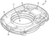
图1A是示例眼可植入设备的透视图。Figure 1A is a perspective view of an example ocular implantable device.
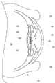
图1B是图1A所示的示例眼可植入设备的电润湿透镜的侧视截面图。Figure IB is a side cross-sectional view of an electrowetting lens of the example ocular implantable device shown in Figure IA.
图1C是位于眼睛内的图1A和图1B中所示的示例眼可植入设备的侧视截面图。1C is a side cross-sectional view of the example ocular implantable device shown in FIGS. 1A and 1B positioned within an eye.
图2A是在第一时间段期间的示例性眼可植入设备的侧视截面图。2A is a side cross-sectional view of an exemplary ocular implantable device during a first time period.
图2B是在第二时间段期间图2A的示例性眼可植入设备的侧视截面图。2B is a side cross-sectional view of the exemplary ocular implantable device of FIG. 2A during a second time period.
图3A是示例眼可安装设备的仰视图。3A is a bottom view of an example eye-mountable device.
图3B是图3A中所示的示例眼可安装设备的侧视图。3B is a side view of the example eye-mountable device shown in FIG. 3A.
图3C是在安装到眼睛的角膜表面上时图3A和图3B所示的示例眼可安装设备的侧视截面图。3C is a side cross-sectional view of the example eye-mountable device shown in FIGS. 3A and 3B when mounted on the corneal surface of an eye.
图4是示例眼可植入和/或眼可安装系统的框图。4 is a block diagram of an example ocular implantable and/or ophthalmic mountable system.
图5A是可用于给电润湿透镜充电的电荷泵的简化电路图。Figure 5A is a simplified circuit diagram of a charge pump that can be used to charge an electrowetting lens.
图5B是可用于给电润湿透镜放电的电荷泵的简化电路图。Figure 5B is a simplified circuit diagram of a charge pump that can be used to discharge an electrowetting lens.
图5C是可以提供给图5A和图5B所示的电荷泵的电压信号的时序图。FIG. 5C is a timing diagram of voltage signals that may be provided to the charge pump shown in FIGS. 5A and 5B .
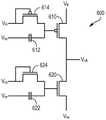
图6A是可用于生成图5C所示的信号的电平转换器的简化电路图。Figure 6A is a simplified circuit diagram of a level shifter that may be used to generate the signal shown in Figure 5C.
图6B是可以提供给图6A所示的电平转换器的电压信号的时序图。FIG. 6B is a timing diagram of voltage signals that may be provided to the level shifter shown in FIG. 6A.
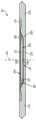
图7是可以在图5A和图5B所示的电荷泵中使用的PIN二极管的简化图。Figure 7 is a simplified diagram of a PIN diode that may be used in the charge pump shown in Figures 5A and 5B.
图8是用于监控和控制图5A和图5B所示的电荷泵的输出电压的电压感测电路的简化图。8 is a simplified diagram of a voltage sensing circuit for monitoring and controlling the output voltage of the charge pump shown in FIGS. 5A and 5B .
图9是示例眼可植入或眼可安装系统的另一框图。9 is another block diagram of an example ocular implantable or ocular mountable system.
图10是示例处理的流程图。10 is a flowchart of an example process.
具体实施方式Detailed ways
在下面的详细描述中,参考构成其一部分的附图。在附图中,除非上下文另外指出,否则相似的符号通常表示相似的组件。在详细描述中,附图和权利要求中描述的说明性实施例并不意味着是限制性的。在不脱离本文提出的主题的范围的情况下,可以利用其他实施例,并且可以进行其他改变。容易理解,可以以各种不同的配置来布置、替换、组合、分离和设计如本文一般地描述的以及在附图中示出的本公开的各方面,所有这些在本文中都可以考虑。In the following detailed description, reference is made to the accompanying drawings which form a part hereof. In the drawings, similar symbols typically identify similar components, unless context dictates otherwise. In the detailed description, the illustrative embodiments described in the drawings and claims are not meant to be limiting. Other embodiments may be utilized, and other changes may be made, without departing from the scope of the subject matter presented herein. It is readily understood that aspects of the disclosure, as generally described herein and illustrated in the drawings, can be arranged, substituted, combined, separated and designed in various configurations, all of which are contemplated herein.
Ⅰ.概述Ⅰ. Overview
各种应用可能需要从低功率电路输出高电压而不牺牲尺寸约束。CMOS工艺可以以小尺寸形式提供低功率数字电路,但工作电压限制可能低于3V。其他半导体工艺可能能够支持高压,但是它们可能导致更大的线宽尺寸,并且可能无法很好地表征。各种升压转换器可能能够产生高压,但是它们可能涉及使用大型的片外组件以实现更高的效率。这样,可能难以在使功耗最小化并满足尺寸受到约束的同时产生高电压输出。Various applications may require high voltage output from low power circuits without sacrificing size constraints. CMOS processes can provide low-power digital circuits in a small form factor, but the operating voltage limit may be less than 3V. Other semiconductor processes may be able to support high voltages, but they may result in larger line sizes and may not be well characterized. Various boost converters may be able to generate high voltages, but they may involve the use of large off-chip components to achieve higher efficiency. As such, it may be difficult to generate a high voltage output while minimizing power consumption and meeting size constraints.
可能希望以小尺寸从低功率电路产生高电压输出的示例应用包括眼可植入设备和眼可安装设备。眼可植入设备可以位于人的眼睛内以向眼睛提供静态或可调节的光功率,并且可以将眼可安装设备安装在人的眼睛的表面上以向眼睛提供静态或可调节的光功率。可以提供这样的静态或可调节的光功率以校正眼睛中光功率和/或调节的缺乏或丧失,例如,校正老花眼、近视、远视、散光、眼睛的损伤或损害、摘除眼睛的晶状体、或校正眼睛的其他某些状况。这些眼可植入设备或眼可安装设备可以包括电子致动透镜,以向眼睛提供可控光功率量。电子致动透镜可以包括电润湿透镜,该电润湿透镜包括两种或更多种不混溶流体,其电润湿透镜内的几何形状可以被电子控制(例如,通过向透镜的两个或更多个电极施加电压),以控制电润湿透镜的整体光功率。Example applications where it may be desirable to generate a high voltage output from a low power circuit in a small size include ocular implantable and ocular mountable devices. The ocular implantable device may be located within a person's eye to provide static or adjustable optical power to the eye, and the ocular mountable device may be mounted on the surface of the person's eye to provide static or adjustable optical power to the eye. Such static or adjustable optical power may be provided to correct a lack or loss of optical power and/or accommodation in the eye, for example, to correct presbyopia, nearsightedness, hyperopia, astigmatism, damage or damage to the eye, removal of the lens of the eye, or correction of Certain other conditions of the eye. These ocular implantable devices or ocular mountable devices may include electronically actuated lenses to provide a controllable amount of optical power to the eye. Electronically actuated lenses can include electrowetting lenses that include two or more immiscible fluids whose geometry within the electrowetting lens can be controlled electronically (e.g., by feeding two or more fluids to the lens). or more electrodes) to control the overall optical power of the electrowetting lens.
这样的眼可植入设备或眼可安装设备可以包括电子设备、天线、电压调节器、电池、光伏电池、传感器或其他元件,以促进该设备的操作,例如,向眼睛提供可控光功率。这样的设备可以例如从隐形眼镜、眼镜、头戴式设备或某些其他源接收射频、光、红外、声或其他形式的功率来为设备的操作供电。设备可以以射频、红外、光或其他电磁信号的形式从外部设备接收无线传输,以指定例如经由电润湿透镜提供的光功率量。设备可以操作传感器以检测物理变量(例如,眼睛的睫状肌施加的调节力)。设备可以使用检测的物理变量来确定要提供的光功率量,或者设备可以使用一些附加或可选的信息或命令源来确定要提供给眼睛的光功率量。Such ocular implantable or ocular mountable devices may include electronics, antennas, voltage regulators, batteries, photovoltaic cells, sensors, or other elements to facilitate operation of the device, for example, to provide controllable optical power to the eye. Such devices may receive radio frequency, light, infrared, acoustic or other forms of power, for example, from contact lenses, glasses, head-mounted devices, or some other source to power operation of the device. The device may receive wireless transmissions from external devices in the form of radio frequency, infrared, optical, or other electromagnetic signals specifying the amount of optical power to provide, for example, via an electrowetting lens. The device may operate sensors to detect physical variables (eg, the accommodation force exerted by the ciliary muscles of the eye). The device may use the detected physical variable to determine the amount of optical power to provide, or the device may use some additional or optional source of information or commands to determine the amount of optical power to provide to the eye.
眼可植入设备或眼可安装设备的电子设备可以包括电压驱动器,该电压驱动器可被操作以调节提供给设备的电润湿透镜的电压。电压驱动器可以包括用于朝向电润湿透镜泵送电荷的第一电荷泵和用于从电润湿透镜上泵走电荷的第二电荷泵。这样,第二电荷泵可以被耦接到电润湿透镜,以便在第一电荷泵已经为透镜充电之后快速地使透镜放电。The electronics of the ocular implantable device or ophthalmic mountable device may include a voltage driver operable to regulate a voltage supplied to an electrowetting lens of the device. The voltage driver may comprise a first charge pump for pumping charge towards the electrowetting lens and a second charge pump for pumping charge away from the electrowetting lens. In this way, a second charge pump can be coupled to the electrowetting lens to quickly discharge the lens after the first charge pump has charged the lens.
电压驱动器还可以包括用于测量和调节第一电荷泵或第二电荷泵的输出电压的电压感测电路。例如,电压感测电路可以包括用于测量输出电压的电容分压器,因为电容分压器比电阻分压器消耗更少的功率。然而,由于电压感测电路的寄生泄漏可能导致电容分压器的电压输出随时间漂移,因此电压感测电路还可以包括附加电容分压器。电压感测电路然后可以周期性地在使用不同电容分压器测量输出电压之间进行切换,以防止电压漂移干扰分压器的输出。这样,电压感测电路在电容分压器之间切换的速率可以取决于电容分压器的一个或更多个电容器的电荷泄漏速率。The voltage driver may also include a voltage sensing circuit for measuring and regulating the output voltage of the first charge pump or the second charge pump. For example, a voltage sensing circuit may include a capacitive divider for measuring the output voltage, since a capacitive divider consumes less power than a resistive divider. However, since parasitic leakage of the voltage sensing circuit may cause the voltage output of the capacitive voltage divider to drift over time, the voltage sensing circuit may also include an additional capacitive voltage divider. The voltage sensing circuit can then periodically switch between measuring the output voltage using a different capacitive divider to prevent voltage drift from interfering with the divider's output. As such, the rate at which the voltage sensing circuit switches between the capacitive dividers may depend on the rate of charge leakage of one or more capacitors of the capacitive divider.
Ⅱ.示例眼可植入设备Ⅱ. Example Ocular Implantable Devices
眼可植入设备(例如,眼内透镜或IOL)可以包括电子设备和电子致动透镜,可操作来为其中植入设备的眼睛提供可控光功率(例如,可控屈光度,焦距或其他形式的光功率或折射属性)。这种眼可植入设备可以包括触觉或其他形成的特征,或根据特定形状形成,从而可将眼可植入设备植入眼睛内或眼睛内的特定位置,例如晶状体摘除后在眼睛的晶状体囊内、在眼睛的前房内、在眼睛的后房内、或沿眼睛的光轴。可以提供控制器、电池、天线、传感器或其他元件来为设备供电,以确定要提供给眼睛的指定光功率量(例如,基于传感器输出或基于接收的无线命令),以及通过将电压、电流或其他电信号施加到电子致动透镜来操作电子致动透镜以提供这样的指定光功率。在一些示例中,电子致动透镜可以是电润湿透镜。An ocular implantable device (e.g., an intraocular lens or IOL) may include an electronic device and an electronically actuated lens operable to provide controllable optical power (e.g., controllable diopter, focal length, or other form of optical power) to the eye in which the device is implanted. optical power or refraction properties). Such an ocular implantable device may include haptic or other formed features, or be formed according to a specific shape, so that the ocular implantable device may be implanted in the eye or in a specific location within the eye, such as in the lens capsule of the eye after lens extraction. In, in the anterior chamber of the eye, in the posterior chamber of the eye, or along the optical axis of the eye. A controller, battery, antenna, sensor, or other element may be provided to power the device to determine a specified amount of optical power to deliver to the eye (e.g., based on sensor output or based on a received wireless command), and by applying voltage, current, or Other electrical signals are applied to the electronically actuated lenses to operate the electronically actuated lenses to provide such specified optical powers. In some examples, the electro-actuated lens can be an electrowetting lens.
图1A是示例眼可植入设备100的透视图。图1B是图1A中示出的示例眼可植入设备100的电润湿透镜110的截面图。注意,图1A和图1B中的相对尺寸不一定按比例,而是仅出于描述示例眼可植入设备100及其电润湿透镜110的布置的目的而呈现。眼可植入设备100包括布置在基底108上的电子器件,电子器件被配置为操作电润湿透镜110以提供可控光功率并提供眼可植入设备100的其他操作。例如,电子器件可以包括一个或更多个控制器102,用于执行各种功能以促进眼可植入设备100的操作,如下面进一步详细描述的;驱动器电路104,用于向电润湿透镜110提供可变高压,以控制由电润湿透镜110提供的光功率;以及电源106(例如,可再充电电池等),用于为控制器(或多个)102、驱动器电路104和/或眼可植入设备100的各种其他电子器件供电。可植入设备100的其他电子器件可以包括调压器、天线、光伏电池、传感器、电极、发送器、接收器或其他各种组件。电子器件可以被配置为接收和/或存储无线能量以向设备100供电(例如,可见光能量、红外光能量、射频电磁能、声能),以与外部设备或系统通信(例如,以接收程序更新,以接收命令的光功率水平),以检测一个或更多个物理变量(例如,光水平、瞳孔直径、眼内压、与眼睛肌肉活动有关的电压、眼睛的睫状肌施加的力、眼睛中一种或多种物质的浓度),可用于确定提供的光功率或可以某种其他方式用于操作电润湿透镜110或促进设备100的某些其他应用。FIG. 1A is a perspective view of an example ocular
眼可植入设备100的电润湿透镜110和/或其他元件可以由一种或多种聚合材料形成。聚合材料可以包括基本上透明的材料,以允许入射光通过眼可植入设备100的电润湿透镜110传输到眼睛的视网膜。聚合材料可以包括与用于形成植入物、视觉校正透镜、IOL或其他可植入设备的材料相似的生物相容性材料,诸如聚对苯二甲酸乙二酯(“PET”),聚甲基丙烯酸甲酯(“PMMA”),硅酮水凝胶,刚性透气性聚合材料,这些的组合等。聚合材料可以包括柔性和/或可折叠的透水材料。例如,聚合材料可以包括包含丙烯酸2-苯基乙基酯单元和甲基丙烯酸2-苯基乙基酯单元的共聚物。聚合物或共聚物的单元可以通过适用的交联剂或单元进行交联,例如通过1,4-丁二醇二丙烯酸酯单元,1,6-己二醇二丙烯酸酯单元或某些其他交联剂或此类试剂的组合进行交联。这样的柔性和/或可折叠材料可以被包括在设备100的构造中,以允许设备100被卷起,被折叠或被操纵,使得可以通过小于例如展开或未折叠的电润湿透镜110的直径的切口来插入设备100。眼可植入设备100可以包括设置在设备的一个或多个外部或内部表面上的涂层材料,例如,以提高设备的生物相容性,控制电润湿透镜的内表面的表面能(例如,以鼓励或防止透镜腔室内的一种或多种流体润湿透镜腔室内的表面),防止离子或其他物质通过,或提供一些其他好处。
电润湿透镜110包括透镜腔室131,在透镜腔室131中布置有第一流体130a和第二流体130b。透镜腔室131由分别成形为杯子和平盖的第一元件120a和第二元件120b形成。电润湿透镜110的第一元件120a和/或第二元件120b的至少一部分可以由聚合材料(例如,本文其他地方列出的聚合材料中的一种)形成,该材料在眼睛的房水中可渗透水(例如,包括1,4-丁二醇二丙烯酸酯单元交联的丙烯酸2-苯基乙基酯单元和甲基丙烯酸2-苯基乙基酯单元的共聚物)。电润湿透镜110的这种水可渗透聚合材料或其他聚合或非聚合材料可以是柔性的,使得电润湿透镜110可以被卷起、被折叠或以其他方式被操纵,例如以便于插入通过眼睛的切口。附加地或可选地,电润湿透镜110的一种或多种密封剂材料(例如,用于将第一元件120a粘附到第二元件120b的密封剂材料)在眼睛的房水中可渗透水。The
注意,电润湿透镜110的腔室131的所示的第一元件120a和第二元件120b意在作为非限制性示例实施例。例如,本文所述的电润湿透镜和/或其透镜腔室可以由比所示出的两个更多或更少的元件(例如,由前元件,后元件和环形元件)构成和/或可以由与在此示出的元件120a、120b不同地配置的元件构成。Note that the illustrated
第一流体130a和第二流体130b是不混溶的(例如,第一流体130a可以是盐水或一些其他水性流体,而第二流体130b可以是油或一些其他非极性流体)且在折射率方面不同。因此,第一流体130a和第二流体130b之间的接触表面(例如,如图1B所示的凸形)可以提供与流体130a、130b的折射率差和接触表面的形状有关的光功率(例如,屈光度,非零焦距)。电润湿透镜110还包括至少两个电极(图2A和图2B所示),被布置在透镜腔室131的相应内表面上。电压、电流或其他电信号可以被施加到至少两个电极上,以电子方式控制第一流体130a和第二流体130b的形状(例如,以控制两种流体130a、130b之间的接触表面的形状),以便控制电润湿透镜110的光功率。The
第一流体130a或第二流体130b中的一个可以包括水溶液。相对于将眼可植入设备100植入其中的眼睛的房水,这种水溶液可以基本上是等渗的。水溶液可以具有与房水(aqueous humor)的克分子渗透压浓度(osmolality)相对应的克分子渗透压浓度,使得如果透镜腔室对房水中的水是可渗透的,则在透镜腔室内的水溶液和眼睛的房水之间会产生少量或基本为零的净水流量。例如,水溶液的克分子渗透压浓度可以大于每千克297毫摩尔,诸如在每千克300毫摩尔至每千克308毫摩尔之间。在另一个实例中,水性流体的克分子渗透压浓度可以在每千克302毫摩尔至每千克306毫摩尔之间。One of the
眼可植入设备100和/或电润湿透镜110(例如,植入设备100植入的眼睛)所提供的总光功率可以与眼可植入设备100的几何形状、折射率或其他性质有关。如上所述,这可以包括透镜腔室131内的第一流体130a和第二流体130b之间的接触表面的形状以及流体130a、130b的折射率。The total optical power provided by ocular
眼可植入设备100的其他元件可以提供静态光功率和/或可控光功率。例如,电润湿透镜110的前表面和/或后表面可以具有弯曲的表面,以提供与这些表面的任一侧上的材料之间(例如,在第一元件120a和/或第二元件120b的聚合材料与眼睛的房水之间,或在聚合材料与第一流体130a或第二流体130b中的一个之间)的折射率变化有关的光功率。Other elements of ocular
眼可植入设备100和/或电润湿透镜110的组件(例如,形成透镜腔室131的第一元件120a或第二元件120b)可以以各种方式被形成为具有弯曲形状。例如,可以采用与形成视力校正隐形眼镜和/或眼内透镜相似的技术,诸如热模制、注射模制、旋涂等,将聚合材料形成为眼可植入设备100的组件。此外,本文所述的眼可植入设备可以具有与图示的眼可植入设备100不同的形状。例如,眼可植入设备可以包括触觉或其他形成的元件,以将眼可植入设备保持在在眼睛内(例如,在眼睛的晶状体囊内)的特定位置,以检测由眼睛的睫状肌施加的调节力,或提供某些其他益处。Components of ocular
图1C是示例眼可植入设备100在被植入眼睛10内时的侧视截面图。眼睛10包括角膜20,通过使上眼睑30和下眼睑32在眼睛10的顶部上方合在一起而覆盖该角膜20。入射光通过角膜20被眼睛10接收,在此处入射光被光学引导到眼睛10的光感应元件(例如,杆和锥等)以刺激视觉。FIG. 1C is a side cross-sectional view of example ocular
在未改变的眼睛中,由视网膜接收的光透射通过晶状体,并由晶状体折射,从而使从环境接收的光聚焦在视网膜上。晶状体位于眼睛的晶状体囊40内,该晶状体囊40通过睫状小带45连接到调节眼睛的肌肉(例如,睫状肌)和其他元件。通过睫状小带45传递的调节力(例如,由调节肌产生的力,由睫状小带45的固有弹性产生的力或由其他来源产生的力)在眼睛中起作用,以使晶状体囊40内的晶状体变形,控制由晶状体提供的光功率。In the unaltered eye, light received by the retina is transmitted through the lens and is refracted by the lens so that light received from the environment is focused on the retina. The lens is located within the
然而,如图1C所示,眼睛10的晶状体已经从晶状体囊40中移出,并且眼可植入设备100已经通过外科手术被放置在晶状体囊40内,使得由视网膜接收的光被透射通过眼可植入设备100的电润湿透镜110,使光被眼可植入设备100的电润湿透镜110和/或其他元件折射。因此,可以操作眼可植入设备100,使得从环境接收的光可以例如通过操作电润湿透镜110提供指定光功率而到达聚焦在视网膜上。However, as shown in FIG. 1C, the lens of the
可以将眼可植入设备100通过形成在眼睛10的角膜20中的切口24插入眼睛10中,然后将其定位在晶状体囊40内。为了将设备100定位在晶状体囊40内,可以在晶状体囊40中形成孔25(例如,通过连续弯曲撕囊术),可以通过孔25移除晶状体(例如,经由晶体超声乳化术),并且可以将设备100通过孔25插入晶状体囊40中。如本文所述的眼可植入设备可位于眼睛10内的替代位置,例如,位于眼睛10的后房11、前房12或玻璃体液13内。The ocular
注意,图1C中的相对尺寸不一定按比例绘制,而是仅出于描述眼睛10内的示例性眼可植入设备100的布置的目的而呈现。此外,这种植入设备可包括多个元件,例如位于多个不同位置。这样的多个元件可以通过电缆或其他某种方式连接。例如,这样的植入设备可以包括:电力接收元件和控制器,布置在后囊11中并且可操作以从眼可安装设备或其他外部系统(未示出)接收无线电力;以及电润湿透镜,布置在晶状体囊40内,通过控制器使用来自电力接收元件的电力,经由连接控制器和电润湿透镜的系绳来操作。Note that the relative dimensions in FIG. 1C are not necessarily drawn to scale, but are presented for the purpose of describing the arrangement of the exemplary ocular
眼可植入设备100可以是可卷起的、可折叠的或其他柔性的,以允许其被卷起、被折叠或以其他方式被操纵成更小的形状。这可以允许将设备100通过更小切口插入通过角膜20。例如,可以将设备100卷起、对折、折成三等分或以其他方式操纵,以允许将设备100通过小于四毫米长的切口24插入。在一些示例中,设备100可以是可卷起的、可折叠的或可操纵的,使得其可以被通过小于2毫米长的切口24插入。在这样的示例中,在眼可植入设备100通过角膜20中的切口24被插入之后,和/或在已经通过其他形成的孔或切口(例如,晶状体囊中的孔25)或通过眼睛的某些其他开口或特征(例如,眼睛10的瞳孔26)被插入之后,眼可植入设备100可以被铺开、展开或操纵成工作形状或状态(例如,基本为扁平状态),以将设备100定位在眼镜10的指定位置。The ocular
注意,尽管将电润湿透镜110示出为包含两种流体130a、130b,但是如本文所述的电润湿透镜可以被制造和分布为仅包含一种流体(例如,包括具有与房水的克分子渗透压浓度相对应的克分子渗透压浓度的水溶液的流体)。稍后可以将第二流体(例如,油或其他非极性流体)添加到电润湿透镜。可以提供仅包含单种流体的这种电润湿透镜,以简化电润湿透镜的植入或制造。例如,通过折叠这样的电润湿透镜,将其插入眼睛中的位置,并且在添加第二流体之前使透镜展开,可以避免第二流体对电润湿透镜的内表面的污染和/或润湿(例如,由于在植入期间第二液体由于折叠,弯曲或操纵电润湿透镜而接触内表面)。然后可以在电润湿透镜已经展开之后来添加第二流体(例如,通过使用针头通过电润湿透镜的隔膜进行注射,经由连接到电润湿透镜的小管进行注射)。Note that although the
如本文所述的电润湿透镜(例如110)可以以各种方式配置,使得可以通过向电润湿透镜的电极施加电压、电流或其他电信号来控制两种或更多种流体(例如,极性流体和非极性流体)的形状。在一些示例中,这可以包括经由电极施加电场,该电场改变电润湿透镜的透镜腔室内的一个或多个表面的有效表面能、表面张力、界面能或其他表面特性,使得不混溶流体中的第一个在一个或更多个表面上后退或前进。当第一流体在一个或更多个表面上后退或前进时,第一流体的整体形状以及第一流体和与第一流体不混溶的第二流体之间的接触表面的整体形状可能会发生变化。如果第一流体和第二流体具有不同的折射率,则光在穿过电润湿透镜时可以被折射,并且该折射的量(以及电润湿透镜的相应光功率)可能与接触表面的形状有关。因此,可以通过将电信号施加到电润湿透镜的电极,例如控制电润湿透镜内的一种或更多种流体的形状和/或控制电润湿透镜的这种流体之间的接触表面的形状,通过电子方式控制电润湿透镜的整体光功率。An electrowetting lens (e.g., 110) as described herein can be configured in various ways such that two or more fluids (e.g., polar fluids and non-polar fluids). In some examples, this may include applying an electric field via electrodes that alters the effective surface energy, surface tension, interfacial energy, or other surface properties of one or more surfaces within the lens chamber of the electrowetting lens such that the immiscible fluid The first of these moves backwards or forwards on one or more surfaces. As the first fluid recedes or advances over one or more surfaces, the overall shape of the first fluid and the overall shape of the contact surface between the first fluid and a second fluid that is immiscible with the first fluid may change Variety. If the first and second fluids have different refractive indices, light may be refracted when passing through the electrowetting lens, and the amount of this refraction (and the corresponding optical power of the electrowetting lens) may vary with the shape of the contact surface related. Thus, the shape of one or more fluids within the electrowetting lens and/or the contact surfaces between such fluids of the electrowetting lens can be controlled, for example, by applying electrical signals to the electrodes of the electrowetting lens shape to electronically control the overall optical power of the electrowetting lens.
图2A示出在第一时间段期间的示例性电润湿透镜200的截面图。电润湿透镜200包括由第一元件210a和第二元件210b限定的透镜腔室201。在示例电润湿透镜200中,透镜腔室201关于中心线202径向对称。第一电极220a沿着电润湿透镜200的第一内表面240a形成并且呈倾斜环的形式。第二电极220b沿着电润湿透镜200的第二内表面240b形成。第一流体230a被布置在透镜腔室201内,并且在图2A所示的第一时间段期间,与第一内表面240a、第一电极220a、电润湿透镜200的第三内表面242和电润湿透镜200的第四内表面244接触。第二流体230b也被布置在透镜腔室201内,并且在第一时间段期间,与第二内表面240b和第二电极220b接触。在第一时间段期间,第一流体230a和第二流体230b之间的接触表面具有第一形状235a。第一流体230a和第二流体230b是不混溶的(例如,第一流体230a是非极性流体,并且第二流体230b是极性流体)并且具有不同的折射率。FIG. 2A shows a cross-sectional view of an
由于第一流体230a和第二流体230b的折射率不同,因此可以折射穿过接触表面的光(例如,沿着中心线202穿过电润湿透镜200的光)。电润湿透镜200的折射度或量以及相关光功率可以与第一流体230a和第二流体230b之间的接触表面的形状有关。Due to the different refractive indices of the
可以通过向电极220a、220b施加电信号,例如通过向电极240a、240b施加电压,来控制接触表面的形状。施加到电极240a、240b的电压与电润湿透镜200的稳态(跟随电润湿透镜因施加电压的变化而发生的任何瞬态变化)光功率和/或流体230a、230b之间的接触表面的形状之间可能存在关系。这样的关系可以与相对于流体230a、230b中的每一个对第一内表面240a的表面能的影响、经由导电的第二流体230b在第一电极220a和第二电极220a之间的有效电容(通过第二流体230,该第二流体230包括导电水溶液,并且与第二电极220b导电和/或电容性电接触)或其他一些因素有关。The shape of the contact surface can be controlled by applying an electrical signal to the
第一电极220a和第二电极220b可以包括布置在透镜腔室201的各个内表面上(例如,分别在第一元件210a和第二元件210b的表面上)的导电材料(例如,铝,金,铜或其他材料)。电极中的一个或两个还可以包括布置在这种导电材料和透镜腔室201的内部之间的介电层。例如,第一电极220a可以包括这样的介电层。可以提供这样的介电层以防止大的直流电流从第一电极220a进入第一流体230a或第二流体230b之一或两者,以在第一电极220a和这种流体之间提供电容性电耦接,以限制可以通过第一电极220a传输到这种流体中的电荷量,或提供其他一些好处。The
这样的介电层可以是沉积在导电材料(例如,通过CVD、旋涂或某些其他工艺)上的单独的材料(例如,聚对二甲苯)。附加地或可选地,第一电极220a的介电层可以由电极的导电材料形成,例如,介电层可以是通过第一电极220a的下面的铝金属的氧化形成的氧化铝的非导电层。这样的介电层可以通过阳极化或其他电驱动反应在电极表面上形成。附加地或可选地,可以通过在透镜腔室201中的流体与电极的材料之间的氧化还原反应来形成这样的介电层。Such a dielectric layer may be a separate material (eg, parylene) deposited on the conductive material (eg, by CVD, spin coating, or some other process). Additionally or alternatively, the dielectric layer of the
在一些示例中,这种介电层的形成和/或维持可能受到透镜腔室201内某些离子的存在(例如,溶解在流体230a、230b中的一种或两种中)的负面影响。例如,氯离子的存在可以使形成在铝电极表面上的氧化铝介电层起凹坑或破坏它。在这样的示例中,屏障可以由不渗透氯化物材料形成,以防止存在于房水中(或在暴露于透镜200的某种其他环境中)的氯离子进入透镜腔室201或进入透镜200的某些其他材料或体积样的材料。这样的材料可以包括聚合材料、金属箔或沉积的金属层或某种其他材料(或多个)。这样的材料对于可见光可以是基本上透明的。In some examples, the formation and/or maintenance of such a dielectric layer may be negatively affected by the presence of certain ions within lens chamber 201 (eg, dissolved in one or both of
可以控制电极220a、220b之间的电压,以便通过控制流体230a、230b之间的接触表面的形状来控制电润湿透镜200的光功率。图2B示出在电压被施加到电极220a、220b使得第一流体230a和第二流体230b之间的接触表面具有第二形状235b的第二时间段期间的电润湿透镜200。结果,在第二时间段期间的电润湿透镜200的光功率不同于在第一时间段期间的电润湿透镜200的光功率。The voltage between the
接触表面的特定形状和/或流体230a、230b的几何形状可以与施加的电压以及多种其他因素有关。这样的因素可以包括流体230a、230b之间的界面能,流体230a、230b与内表面240a、240b、242、244之间的界面能,内表面240a、240b、242、244的几何形状,电极220a,220b的几何形状和/或第一电极220a的介电层的几何形状。可以指定这些因素中的一个或更多个,以便影响流体230a、230b之间的接触表面的形状,影响流体230a、230b在透镜腔室201内的几何形状和/或位置,以影响在施加的电压和电润湿透镜200的光功率之间的关系,或者影响电润湿透镜200的其他一些感兴趣的性质。The particular shape of the contact surface and/or the geometry of the
这可以包括向流体(或多个)中添加表面活性剂、极性和/或离子性物质、非极性物质、或指定第一流体230a和/或第二流体230b的组成,以控制流体230a、230b之间的界面能,和/或控制流体与透镜腔室的内表面240a、240b、242、244之间的界面能。附加地或可选地,可以指定组成内表面240a、240b、242、244的材料的成分,以控制内表面和流体之间的界面能。This may include adding surfactants, polar and/or ionic substances, non-polar substances, or specifying the composition of the
这可以包括选择第一元件210a和第二元件210b的块状材料和/或向透镜腔室201的内表面提供一个或多个涂层或表面处理。例如,第一流体230a可以是油或其他非极性的,并且第一内表面240a、第三内表面242或第四内表面244中的一个或更多个可以是超疏水的或疏水的。此外,第二流体230b可以是极性流体(例如,可以包括具有与人的房水的克分子渗透压浓度相同的克分子渗透压浓度的盐溶液或其他水溶液),并且第二内表面240b可以是超亲水的或亲水的(例如,通过包括表面涂层,通过包括表面特征或纹理,通过暴露于氧化过程或通过某些其他方式)。This may include selecting the bulk material of the
可以指定这样的涂层或材料在透镜腔室201的内表面上的分布和/或这样的表面的几何形状,以使第一流体230a沿着中心线202或沿着电润湿透镜200的某些其他指定轴线居中。这可以包括根据距中心线202的距离向内表面施加不同涂层或其他材料。另外或可选地,第一电极220a的电介质的厚度或其他性质可以根据距中心线202的距离而变化,使得当在电极220a、220b之间施加电压时,施加到第一流体230a和/或第二流体230b的电和/或界面力趋于使第一流体230a沿着中心线202居中和/或使第一内表面240a上的流体230a,230b之间的边界与以中心线202为中心的圆一致。The distribution of such coatings or materials on the interior surfaces of the
电润湿透镜200可以渗透眼睛的房水中的水或其他物质(例如,离子)。这可以包括电润湿透镜200至少部分地由对房水中的水(或其他物质)可渗透的聚合材料构成。在电润湿透镜200可以渗透房水中存在的物质的示例中,流体230a、230b中的一个或两个可以包括与房水中的物质浓度相对应的物质浓度,例如,以防止从房水到透镜腔室201的物质的净流,反之亦然。The
附加地或可选地,可以使电润湿透镜200对于房水中的此类物质不可渗透。这可以包括由物质不可渗透的材料构造透镜腔室201。另外地或可选地,可以由这种不可渗透材料形成屏障层或涂层,以防止物质进入透镜腔室201或电润湿透镜200的某些其他元件或结构。例如,屏障可以由不可渗透氯化物的材料形成,以防止房水中存在的氯离子进入透镜腔室201或进入透镜200的某些其他材料或体积。这样的材料可以包括聚合材料、金属箔或沉积金属层或一些其他材料(或多个)。这样的材料对于可见光可以是基本上透明的。Additionally or alternatively, the
在一些示例中,电润湿透镜200的组件可以由自修复材料组成。例如,透镜腔室201可以至少部分地由自修复材料形成。可以提供这样的自修复材料以保持透镜腔室201或电润湿晶状体200的其他体积的完整性,再次,大量流体流入或流出这样的体积(例如,在透镜腔室201和眼睛的房水之间)。在一些示例中,通过暴露于在电润湿透镜200的房水和/或流体230a、230b中存在的氯离子或其他物质,这样的自修复材料可能被降解和/或它们的自修复能力可能被减弱。在这样的示例中,不可渗透材料(例如,不可渗透氯化物材料)可以被用于在房水中存在的氯离子或其他物质与自修复材料之间形成屏障。In some examples, components of
III.示例眼可安装设备III. EXAMPLE EYE-MOUNTABLE DEVICES
眼可安装设备(例如,隐形眼镜)可以包括:电子致动透镜,诸如电润湿透镜(例如,图2A和2B中描绘的电润湿透镜200);驱动器电路,用于驱动电子致动透镜;一个或更多个控制器,用于控制驱动器电路;以及电源,用于为控制器和驱动器电路供电。这样的眼可安装设备可以根据多种形状中的一种来形成,使得可以将眼可安装设备可移除地安装到眼睛,例如,可以将眼可安装设备成形为安装到眼睛的角膜上,在瞳孔和虹膜之上。An eye-mountable device (e.g., a contact lens) may include: an electronically actuated lens, such as an electrowetting lens (e.g.,
图3A是示例眼可安装电子设备310的仰视图。图3B是图3A中示出的示例眼可安装电子设备的侧视图。注意,图3A和图3B中的相对尺寸不一定按比例绘制,而是仅出于描述示例眼可安装电子设备310的布置的目的而呈现。眼可安装设备310由形状为弯曲盘的聚合材料320形成。聚合材料320可以是基本透明的材料,以在将眼可安装设备310安装到眼睛上时允许入射光透射到眼睛。聚合材料320可以是生物相容性材料,类似于在验光中用于形成视力校正和/或美容隐形眼镜的那些,诸如聚对苯二甲酸乙二醇酯(“PET”),聚甲基丙烯酸甲酯(“PMMA”),硅水凝胶,硬质,透气聚合材料,这些的组合等。聚合材料320可以被形成为一侧具有凹面326,适合装配在眼睛的角膜表面上。盘的相对侧可具有凸面324,在眼可安装设备310被安装到眼睛上时不干扰眼睑的运动。圆形外侧边缘328连接凹面324和凸面326。FIG. 3A is a bottom view of an example eye-mountable
眼可安装设备310可以具有类似于视力校正和/或美容隐形眼镜的维度,诸如,直径为大约1厘米,厚度为大约0.1至大约0.5毫米。然而,提供的直径和厚度值仅用于说明目的。在一些实施例中,可以根据佩戴者眼睛的角膜表面的尺寸和/或形状来选择眼可安装设备310的维度。The eye
聚合材料320可以以各种方式利用弯曲形状形成。例如,可以采用与形成视力校正隐形眼镜的技术类似的技术,诸如热成型、注射成型、旋铸等,以形成聚合材料320。当将眼可安装设备310安装在眼睛中时,凸面324面向外部环境,而凹面326面向内朝向角膜表面。因此,凸面324可以被认为是眼可安装设备310的外顶表面,而凹面326可以被认为是内底表面。The
电子致动透镜330和基底340被嵌入在聚合材料320中。致动透镜330可以与图2A和图2B所示的电润湿透镜200相似或相同,并且可以被嵌入在聚合材料320的中心区域,使得使入射光通过致动透镜330传输到眼睛的眼睛感应部分。可以将基底340嵌入以沿着聚合材料320的外周放置,诸如部分或完全围绕致动透镜330。基底340不会干扰视觉,因为它离眼睛太近以至于无法聚焦并且被定位成远离聚合材料320的中心区域。基底340可以由透明材料形成,以进一步减轻对视觉的任何影响。Electronically actuated
基底340可以成形为平坦的圆环(例如,具有中心孔的盘)。基底340的平坦表面(例如,沿着径向宽度)可以被用作用于安装诸如芯片的电子器件(例如,通过倒装芯片安装)或电池以及用于对导电材料进行图案化(例如,通过沉积技术)的平台,以形成电极(例如,电化学电池的阳极和/或阴极,电化学传感器的电极),天线和/或连接。基底340和聚合材料320可以关于共同的中心轴线大致圆柱形对称。基底340可以具有例如约10毫米的直径,约1毫米的径向宽度(例如,外半径比内半径大1毫米)以及约50微米的厚度。然而,提供这些尺寸仅出于示例目的,并且绝不限制本公开。可以以各种不同的形状因子来实现基底340。
控制器350、驱动器电路360、天线370、电容传感器系统380和电池390被布置在嵌入基底340上。控制器350可以是包括逻辑元件的芯片,被配置为从电池390接收电力以及操作驱动器电路360驱动致动透镜330。控制器350通过也位于基底340上的互连电连接到电池390、电容传感器系统380、天线370和驱动器电路360。天线370、互连和任何导电电极(例如,电池390的阳极和阴极)可以通过诸如淀积,光刻等的用于精确图案化这种材料的工艺由在基底340上图案化的导电材料形成。在基底340上图案化的导电材料可以是例如金、铂、钯、钛、碳、铝、铜、银、氯化银,由贵金属形成的导体,金属,这些的组合等。
如图3A所示,其是面向眼可安装设备310的凹面326的视图,电池390、电容传感器系统380、天线370、驱动器电路360和控制器350被安装到基底340面对凹面326的一侧。然而,这些电子器件可以被安装在基底340的“向内”面向侧(例如,最靠近凹面326)或“向外”面向侧(例如,最靠近凸面324)。此外,在一些实施例中,一些电子组件可以被安装在基底340的一侧,而其他电子组件可以被安装在相对侧,并且两者之间的连接可以通过导电材料穿过基底340。As shown in FIG. 3A , which is a view facing the
如图所示,天线370可以采用环形天线的形式。这样的环形天线可以是沿着基底340的平坦表面图案化的导电材料层,以形成平坦导电环。在某些情况下,可以形成这种环形天线而无需制作完整环形。例如,这样的天线可以具有切口,以为控制器350或设备310的其他元件留出空间。然而,这样的环形天线也可以被布置成连续的导电材料带,一次或多次完全包裹在基底340的平坦表面周围。例如,可以在基底340的与控制器350、驱动器电路360和电池390相对的一侧上图案化具有多个绕组的导电材料带。这种缠绕天线(例如,天线引线)的端部之间的互连可以穿过基底340到达控制器350。这样的环形天线可以用于促进附加功能,例如,提供用于与其他设备(例如,与从眼可安装设备310通过环形天线和/或通过一些其他装置接收无线电力的植入设备)通信的装置,以提供用于为眼可安装设备310的可再充电电池(例如,电池390)充电的装置,或提供一些其他功能。As shown,
电容传感器系统380可以被布置在基底340上,以类似于电容触摸屏的方式感测眼睑重叠。通过监视眼睑重叠的量和位置,控制器350可以测量来自电容传感器系统380的反馈信号,以确定眼睛的近似注视方向和/或焦距。然后,控制器350可以使用确定的眼睛的注视方向和/或焦距来控制提供给眼睛的光功率。例如,基于测量的注视方向和/或焦距,控制器350可以调节驱动器电路360提供给致动透镜330的电压或电流。在所示的实施例中,电容传感器系统380沿着基底340的外边缘被分布在天线370周围周边。在其他实施例中,电容传感器系统380可以以可替代的方式被分布在眼可安装设备310内或上。在所示的实施例中,电容传感器系统380包括多个与公共读取线耦接的分立电容传感器;然而,各种实现方式包括单个细长电容传感器,多个离散电容传感器,经由公共读取线并联耦接的多个分立电容传感器,并联耦接分立电容传感器的多个独立分支等。在另一个实施例中,代替电容感测或除电容感测之外,光电探测器可以被不同地布置在眼可安装设备310上或眼可安装设备310中以提供基于光水平(例如,包括这种水平的变化等)的观看动作的监控。A
此外,注意,电池390的配置旨在作为非限制性示例。眼可安装设备310可以包括多个离散电池,这些电池可以串联、并联或根据其他考虑进行电连接。可以将电池390的一个或更多个元件(例如,阳极、阴极)形成为图案化在基底340上的导电迹线。另外或可选地,可以独立于基底340形成电池390,然后将其布置在基底上340(例如,通过使用焊料,使用粘合剂,通过将电池390和基底340彼此靠近地灌封在用于形成聚合材料320的前体材料中)。电池390可以是可充电的(例如,可以具有锂聚合物化学物质)或可以是不可充电的。在一些示例中,电池390可以通过暴露于眼泪或眼睛的一些其他水性流体来激活(例如,电池390可以是锌电池,其通过暴露于溶解有氧气的水性流体来激活)。Also, note that the configuration of
图3C是示例眼可安装设备310在安装到图1C所示的眼睛10的角膜表面20时的侧视截面图。如图3C中的截面图所示,基底340可以被倾斜,使得基底340的平坦安装表面大致平行于凹面326的相邻部分。如上所述,基底340是具有向内表面(更靠近聚合材料320的凹面326)和向外表面(更靠近凸面324)的扁平环,并且基板340可以具有电子组件和/或安装到一个或两个安装表面上的图案化导电材料。3C is a side cross-sectional view of an example eye-
如在图3C的横截面图中进一步示出的,眼可安装设备310可以被定位在角膜表面20上,使得致动透镜330与眼睛10的瞳孔26基本上对准。以这种方式,穿过瞳孔26到达眼睛10的晶状体40的光可以首先穿过眼可安装设备310的致动透镜330。与以上讨论一致,致动透镜330可以采用各种形式,并且可以与图2A和2B所示的电润湿透镜200类似或相同。As further shown in the cross-sectional view of FIG. 3C , eye
如进一步所示,可以将致动透镜330机械地耦接到基底340,并且通过一个或更多个互连电耦接到眼可安装设备310的各种其他组件,诸如控制器350。因此,与上面的讨论一致,控制器350可以通过向电子致动透镜施加电压、电流或其他电信号来操作致动透镜330调节致动透镜330的光功率(并且因此调节提供给眼睛10的总光功率)。As further shown,
眼可安装设备310还可以包括与眼可安装设备310的应用有关的元件,以检测由眼睛产生的调节力(例如,通过眼睛10的睫状小带45向眼睛10的晶状体囊40施加的调节力),并向眼睛10提供与检测的调节力有关的可控光功率。这些元件可以包括被配置为检测调节力的调节传感器。这样的调节传感器可以包括植入晶状体囊内的传感器或传感器接口和/或位于眼可安装设备310上并被配置为检测眼可安装设备310本身的触觉的传感器。这样,眼可安装设备310还可以包括一个或更多个发送器和/或接收器,被配置为与调节传感器通信(例如,通过发送和/或接收光,射频电磁场或其他无线传输)以接收来自调节传感器的指示检测的调节力的信息。因此,眼可安装设备310的控制器350可以被配置为基于检测的调节力来调整提供给被致动镜片330的电压或电流,以向眼睛10提供可控光功率。The eye-
眼可安装设备310还可以包括一个或更多个传感器(未示出),被配置为检测身体的生理参数(例如,眼泪或其他体液中的分析物的浓度,巩膜或眼睑的部分皮下血管系统中的血液量,血液的氧化状态或眼睑是否闭合),设备环境的属性(例如,环境光照,大气压力或温度),设备属性(例如,加速或方位),或检测其他一些信息。这样的传感器可以包括加速度计,电极(例如,电化学分析物传感器的电极,被配置为检测心电图,眼电图,肌电图或一些其他生物电信号的电生理传感器的电极),光检测器,温度计,陀螺仪,电容传感器,压力传感器,应变仪,发光器,麦克风或被配置为检测与感兴趣属性有关的一个或多个物理变量的其他元件。如本文所示的眼可安装设备可操作这样的元件以在一个或多个时间点测量生理参数或其他感兴趣的信息。这样的测量属性和/或参数可以被记录(例如,在设备的存储器中,例如,用于以后传输到外部系统),被传输到外部系统,使用设备的元件(例如,使用显示器,使用一个或多个发光元件)来指示,用于确定用户的健康状况或根据某些其他应用使用。The eye-
如上所述,眼可安装设备310的电池可以是一次性的(即不可充电的)或可以是可充电的。在电池是可再充电的示例中,眼可安装设备可以以各种方式被配置,以促进接收能量以对电池充电。眼可安装设备310可以包括:天线(例如,环形天线),用于接收射频电磁能;光伏电池或其他光接收元件(或多个),用于接收光能;两个或更多个电极,用于接收电流(例如,通过与充电器的相应电极直接接触和/或通过布置眼可安装设备的导电流体),或用于从外部设备接收能量的其他一些装置。例如,环形天线可以被用于接收射频电磁能以对电池充电。As noted above, the battery of eye-
Ⅳ.设备的示例电子器件Ⅳ. EXAMPLE ELECTRONICS OF DEVICES
图4是系统400的框图,该系统400可以被实现为诸如图1A所示的眼可植入设备100的眼可植入设备、眼外设备(诸如图3A-图3C中描绘的眼可安装设备310的眼可安装设备、可头戴设备、一些其他类型的身体可安装设备、智能电话等)或两者的组合。系统400包括作为集成电路402的一部分和/或被配置为与集成电路402的接口的各种电子组件。特别是,系统400包括控制器410、致动透镜420、致动透镜驱动器430、一个或更多个传感器440、一个或更多个传感器接口442、通信接口450以及一个或更多个电源460,诸如电池(例如,一次性碱性电池,可充电锂聚合物电池),太阳能电池或,用于为控制器410或系统400的其他元件供电的其他一些能源。4 is a block diagram of a
如图所示,控制器410、致动透镜驱动器430、传感器(或多个)440和通信接口450被包括在集成电路402中。然而,这意味着作为非限制性示例,并且在其他实施例中,系统400的附加的或更少的元件可以被包括在集成电路402中。集成电路402可以被布置在基底上,并且基底可以采取各种形式。例如,在系统400是眼可植入设备的实施例中,基底可以类似于图1A中描绘的眼可植入设备100的基底108,并且在系统的实施例中。As shown,
致动透镜驱动器430可操作来控制由致动透镜420提供给眼睛的光功率。致动透镜420可以包括电润湿透镜,诸如图2A和图2B中所示的电润湿透镜200,并且操作致动透镜420以控制透镜的光功率可以包括向电润湿致动透镜的电极施加电压。这可能涉及向透镜施加电压,该电压的幅度大于提供给控制器410或系统400的其他组件的电压的幅度。这样,为了控制电润湿透镜的光功率,驱动器430可以包括用于提供更高电压(例如,大于±20V的电压)的高压(HV)驱动器432。HV驱动器432可以包括电荷泵、电压倍增器或各种其他类型的电压转换器以提供这种更高的电压。如进一步所示,致动透镜驱动器430可以包括反馈电路434,用于控制HV驱动器432的输出电压,并因此控制由致动透镜420提供给眼睛的光功率。下面参照图5A-图9更详细地示出HV驱动器432和反馈电路434的示例。Actuation lens driver 430 is operable to control the optical power provided to the eye by actuation lens 420 . Actuation lens 420 may comprise an electrowetting lens, such as
传感器(或多个)440可以包括被配置为检测生理性质(例如,眼睛的瞳孔直径、压力或力或生物电势)、环境参数(例如,环境光水平、用户的两眼之间的距离和用户注视的对象)的传感器,以检测用户的眼睛和/或眼睑的运动(例如,检测眼睛的聚散度),或检测可能与眼外设备和/或眼可植入设备的操作有关的物理参数。在特定示例中,传感器(或多个)440可以包括眼可植入设备的调节传感器,被配置为例如通过经由传感器接口(或多个)442检测晶状体囊内的力或压力来直接或间接地检测施加在眼睛的晶状体囊上的调节力,可以包括被布置在晶状体囊中的弹性材料,用于检测睫状肌电活动的接口或一些其他装置。与上面的讨论一致,调节传感器的特定示例可以包括用于感测眼睑重叠的量和位置的电容传感器系统(例如,图3A中的电容传感器系统380)。Sensor(s) 440 may include sensors configured to detect physiological properties (e.g., pupil diameter of the eye, pressure or force, or bioelectric potential), environmental parameters (e.g., ambient light level, distance between the user's eyes, and user Gaze objects) to detect movement of the user's eyes and/or eyelids (e.g., to detect eye vergence), or to detect physical parameters that may be relevant to the operation of extraocular devices and/or ocular implantable devices . In particular examples, sensor(s) 440 may include an accommodation sensor of an ocular implantable device configured to directly or indirectly, for example, by detecting force or pressure within the lens capsule via sensor interface(s) 442 Sensing the accommodative force exerted on the lens capsule of the eye may include an elastic material disposed in the lens capsule, an interface for detecting ciliary myoelectric activity, or some other device. Consistent with the discussion above, a particular example of an accommodation sensor may include a capacitive sensor system (eg,
通信接口450可以被操作为在眼可植入设备与眼外设备之间或者在两个或更多个眼外设备之间无线地发送传感器数据、命令、电力或其他信号。例如,眼可植入设备和/或眼外设备可以包括发光元件(例如,LED、激光器、VCSEL)、射频电磁能量传输元件(例如,天线、线圈),被配置为将时变电流注入人体组织或体液的元件(例如电极)、或被配置为传输的其他元件。通信接口450可以被配置为控制从通信接口450发送的无线信号的强度、相位、频率、极化、方向或一些其他属性以指示信息。Communication interface 450 may be operable to wirelessly transmit sensor data, commands, power, or other signals between the ocular implantable device and the extraocular device, or between two or more extraocular devices. For example, ocular implantable devices and/or extraocular devices may include light emitting elements (e.g., LEDs, lasers, VCSELs), radiofrequency electromagnetic energy delivery elements (e.g., antennas, coils) configured to inject time-varying electrical currents into human tissue Or bodily fluid elements (such as electrodes), or other elements configured to transmit. Communication interface 450 may be configured to control the strength, phase, frequency, polarization, direction, or some other property of wireless signals sent from communication interface 450 to indicate information.
系统400的眼可植入设备和/或眼外设备可以包括附加或替代元件,并且可以包括比图4所示的元件更多或更少的元件。例如,眼可植入设备可以包括被配置为向眼外设备发送无线信号的元件,并且眼外设备可以包括被配置为接收此类发送信号的元件。在这样的示例中,眼可植入设备和眼外设备可以另外分别包括发送器和接收器。另外地或可选地,所示的通信接口450可以被配置为一个或更多个收发器,以促进双向通信和/或与被配置为促进双向通信的其他元件共同共享一个或更多个元件(例如,天线、滤波器、线圈、功率调节系统)。The ocular implantable device and/or extraocular device of
注意,为了便于描述,结合功能模块来描述图4中所示的框图。然而,系统400的实施例可以包括眼外设备和/或眼可植入设备,其布置有以单个芯片,集成电路和/或物理特征实现的一个或多个功能模块(“子系统”)。也就是说,图4中的功能块不必实现为分离的模块。此外,图4中描述的一个或多个功能模块可以通过彼此电连接的单独封装芯片或其他组件来实现。此外,注意,本文所述的眼外设备和/或眼可植入设备可以包括图4所示的组件的附加或替代组件(例如,附加传感器,致动透镜,显示器,视网膜刺激器阵列,电极,电池,控制器,发送器,接收器,刺激器等)。Note that, for convenience of description, the block diagram shown in FIG. 4 is described in conjunction with functional modules. However, embodiments of the
图5A是电荷泵500的电路图,可以用于将电荷泵送到电润湿透镜(例如,提供正电压)。所示的电荷泵500是迪克森(Dickson)电荷泵,但是应当理解,电荷泵500可以采用各种其他形式,诸如科克罗夫特-沃尔顿(Cockcroft-Walton)电压倍增器、格林纳赫(Greinacher)电压倍增器等。电荷泵500可操作以接收DC输入电压Vin并输出DC输出电压Vout,其中Vout的幅度大于Vin。如图所示,电荷泵500包括由虚线502分隔的多个级,并且每个级包括二极管和电容器。例如,第一级包括第一二极管D1和耦接到第一二极管D1的阴极的第一电容器C1,第二级包括第二二极管D2和耦接到第二二极管D2的阴极的第二电容器C2,依此类推,直到第n级。每级的输入在其二极管的阳极,且其输出在其二极管的阴极。例如,第一级的输入在第一二极管D1的阳极,而第一级的输出在第一二极管D1的阴极。FIG. 5A is a circuit diagram of a
如进一步所示,电荷泵500的每级耦接到参考电压信号Vclk1或Vclk2。奇数级耦接到Vclk1,且偶数级耦接到Vclk2。图5C是可以与电荷泵500结合使用的参考电压信号Vclk1和Vclk2的时序图。如图5C所示,Vclk1和Vclk2可以是彼此反相的时钟脉冲信号,使得当Vclk2为高时Vclk1为低,且当Vclk2为低时Vclk1为高。此外,参考电压信号Vclk1和Vclk2可以在0V和Vin的电压电平之间交替。As further shown, each stage of the
在一些示例中,参考电压信号Vclk1和Vclk2可以使用振荡器或数字时钟信号来生成。然而,典型的振荡器或数字时钟可能不能输出足够的电流来驱动电荷泵500。因此,电平转换器电路可以被用于基于低功率振荡器或数字时钟信号来产生参考电压信号Vclk1和Vclk2。In some examples, the reference voltage signals Vclk1 and Vclk2 may be generated using an oscillator or a digital clock signal. However, a typical oscillator or digital clock may not be able to output enough current to drive the
图6A是可用于产生参考电压信号Vclk1和Vclk2的电平转换器600的电路图。如图所示,电平转换器600包括pMOS晶体管610和nMOS晶体管620,在pMOS晶体管610的源极端子处的Vin与nMOS晶体管620的源极端子处的Vss(例如0V)的电压轨之间以互补金属氧化物半导体(CMOS)配置连接。FIG. 6A is a circuit diagram of a
电平转换器600的输出Vclk耦接到pMOS晶体管610和nMOS晶体管620的漏极端子。这样,当pMOS晶体管610导通并且nMOS晶体管620截止时,输出Vclk被上拉至Vin。类似地,当pMOS晶体管610截止并且nMOS晶体管620导通时,输出Vclk被下拉至Vss。因此,通过以交替模式导通pMOS晶体管610和nMOS晶体管620,输出Vclk可以在Vin和0V之间交替,如图5C所示。并且通过使两个电平转换器600彼此反相操作,电平转换器600的输出可以被用作参考电压Vclk1和Vclk2,如图5A所示。The output Vclk of
为了以交替模式导通pMOS晶体管610和nMOS晶体管620,可以通过第一滤波电容器612将第一时钟信号Vcp耦接到pMOS晶体管610的栅极端子,并且可以通过第二滤波电容器622将第二时钟信号Vcn耦接到nMOS晶体管620的栅极端子。To turn on
图6B是可以被耦接到电平转换器600的pMOS晶体管610和nMOS晶体管620的栅极端子的时钟信号Vcp和Vcn的时序图。如图所示,时钟信号Vcp和Vcn可以在0V和逻辑高电压电平Vlo之间转变,并且这些时钟信号被施加到pMOS晶体管610和nMOS晶体管620的栅极端子。电平转换器600还可以包括耦接到pMOS晶体管610的栅极端子的二极管连接的pMOS晶体管614,以及耦接到nMOS晶体管620的栅极端子的二极管连接的nMOS晶体管624。这些二极管连接的晶体管614、624可以被用作非线性电阻,使得当Vcp转变到Vlo时,pMOS晶体管610的栅极端子处的电压被设置为Vin,并且当Vcn转变到0V时,nMOS晶体管620的栅极端子处的电压被设置为Vss。6B is a timing diagram of clock signals Vcp and Vcn that may be coupled to the gate terminals of
此外,时钟信号Vcp和Vcn可以被配置为彼此同相转变,以便以交替模式导通pMOS晶体管610和nMOS晶体管620。当pMOS晶体管610和nMOS晶体管620的栅极电压都为高时,pMOS晶体管610截止并且nMOS晶体管导通。当pMOS晶体管610和nMOS晶体管620的栅极电压都为低时,pMOS晶体管610导通并且nMOS晶体管截止。因此,通过将时钟信号Vcp和Vcn配置为彼此同相,可以以交替模式导通pMOS晶体管610和nMOS晶体管620。Additionally, clock signals Vcp and Vcn may be configured to transition in phase with each other to turn on
如图6B进一步所示,时钟信号Vcp和Vcn可以具有不同的占空比。为了避免pMOS晶体管610和nMOS晶体管620同时导通的情况,这可以通过使用“先通后断”开关来减小或消除直通电流。如果pMOS晶体管610和nMOS晶体管620两者同时导通,则晶体管610、620有效地在Vin和Vss,之间形成短路路径,从而浪费功率并降低了电平转换器600的效率。当使用电池或一些其他有限能源为系统供电时,这尤其成问题,如上述的眼可植入和眼可安装系统的情况。因此,如图6B所示,时钟信号Vcn可以被配置为在时钟信号Vcp具有其上升沿转变之后的时间延迟630处发生其上升沿转变(例如,其从0V到Vlo的转变)。类似地,时钟信号Vcn还可以被配置为在时钟信号Vcp具有其下降沿转变之后的时间延迟640处发生其下降沿转变(例如,其从Vlo到0V的转变)。以此方式,当Vcp为逻辑低时,Vcn将不会为逻辑高,使得直到在pMOS晶体管610截止之后nMOS晶体管620才被导通,并且直到nMOS晶体管620截止之后pMOS晶体管610才被导通。As further shown in FIG. 6B , the clock signals Vcp and Vcn may have different duty cycles. To avoid the situation where
在一些示例中,为了进一步降低功耗并提高系统效率,电荷泵500的二极管D1-Dn可以是基底上方的PIN二极管(above-substrate PIN diode),与传统的基于阱的PN二极管(well-based PN diode)相比,其具有更低的反向偏置电流泄漏。图7是示例PIN二极管700的简化图。二极管700包括半导体基底702(例如,硅基底)和在基底702顶部上的浅槽隔离(STI)层704。STI层704可以包括一种或更多种介电材料(例如,二氧化硅),其将位于STI层704上方的电子器件与基底702电绝缘。In some examples, in order to further reduce power consumption and improve system efficiency, the diodes D1 -Dn of the
二极管700还包括在STI层704的顶部上由p型掺杂区域706、n型掺杂区域710以及在p型掺杂区域706和n型掺杂区域之间的未掺杂本征区域708形成的PIN结。可以在p型掺杂区域706上形成阳极接触712(例如,由p型多晶硅),并且可以在n型掺杂区域710上形成阴极接触714(例如,由n型多晶硅)。注意,图7中的相对尺寸不一定按比例绘制,而是仅出于描述示例PIN二极管700的布置的目的而呈现。The
再次参照图5A,当电荷泵500在操作中并达到稳态时,第一级中的第一电容器C1将被以大约等于Vin的电压充电。第一级的输出等于参考电压Vclk1与第一电容器C1两端的电压之和,使得当参考电压Vclk1从0V转变为Vin时,第一级的输出、并因此是第二级的输入大约等于Vin电压的两倍。这样,在稳态下,第二级中的第二电容器C2将用大约等于2Vin的电压被充电。并且,当第二级的参考电压Vclk2从0V转变为Vin时,第二级的输出且是第三级的输入大约等于Vin电压的三倍。电荷泵的每个后续级都以类似的方式起作用。因此,除了第n级以外,电荷泵500的每个级将输出电压增加电压Vin,第n级用作电压整流器以在Vout处产生DC输出。因此,可以通过调整级数和/或通过调整Vin的幅度来改变电荷泵500的输出Vout。Referring again to FIG. 5A , when the
此外,应该理解,上面在理想条件下描述了示例电荷泵500,并且由于跨二极管D1-Dn两端的电压降和/或在电路中的其他损耗源,每个电容器C1-Cn两端的实际电压可能会略低。Furthermore, it should be understood that the
实际上,电荷泵500可以被耦接到眼可植入设备或眼可安装设备的电润湿透镜,以在电润湿透镜的电极之间施加输出电压Vout。以这种方式,调整输出电压Vout可以调整电润湿透镜的电极两端的电压,并且因此可以如上所述调整电润湿透镜的光功率。In practice, the
如以上进一步指出的,电润湿透镜可以具有电容特性,使得电润湿透镜的电极可以趋于保持电荷并抵抗电极两端的任何电压变化。例如,如果电荷泵500被耦接到电润湿透镜的电极并且将电极充电至特定电压,并且然后如果电荷泵500从电润湿透镜解耦,则电润湿透镜可以趋于保持在所充电的电压或缓慢放电。然而,为了快速改变电润湿透镜的光功率,可能期望将电润湿透镜配置为快速放电。根据本公开,这可以通过将第二电荷泵耦接到电润湿透镜的电极来实现,该电润湿透镜被配置为主动地将电荷从透镜上泵走。As noted further above, an electrowetting lens may have capacitive properties such that the electrodes of the electrowetting lens may tend to hold charge and resist any change in voltage across the electrodes. For example, if the
图5B是电荷泵510的电路图,该电荷泵510可以被用于将电荷从电润湿透镜上泵走(例如,向其提供负电压)。如图所示,除了二极管D1-Dn的极性相反以外,图5B中的电荷泵510以与图5A中的电荷泵500相似的方式布置,使得每级的输入在每个二极管的阴极并且每级的输出在每个二极管的阳极。以这种方式,电荷泵510被配置为倍增Vin以在Vout处产生负电压,而不是倍增Vin以在Vout处产生正电压。因此,在实践中,图5A中的电荷泵500可以被耦接到电润湿透镜以给电润湿透镜充电,并且为了给电润湿透镜放电,可以将电荷泵500从电润湿透镜解耦,并且作为代替,图5B的电荷泵510可以耦接到电润湿透镜。5B is a circuit diagram of a
作为另一示例,图5A中的电荷泵500和图5B中的电荷泵510可以被同时耦接到电润湿透镜,并且电荷泵500、510可以被操作,使得仅电荷泵500、510中的一个在给定时间处于活动状态。例如,为了将电荷泵送到电润湿透镜,可以开启电荷泵500(例如,通过将图5C中的时钟信号施加到图5A中的Vclk1和Vclk2输入),然后可以关断电荷泵510(例如,通过将图5B中的Vclk1和Vclk2输入绑定到地电压)。类似地,为了将电荷从电润湿透镜上泵走,可以开启电荷泵510(例如,通过将图5C中的时钟信号施加到图5B中的Vclk1和Vclk2输入),并且可以关断电荷泵500(例如,通过将图5A中的Vclk1和Vclk2输入绑定到地电压)。此外,在该示例中,因为电荷泵500、510的输出被电连接,所以通过电荷泵510的每个二极管D1-n的一系列电压降来解决电荷泵500的输出电压Vout与电荷泵510的输入电压Vin之间的电压差。这样,为了最小化由于流过电荷泵510的二极管D1-n的二极管电流而引起的功率损失,电荷泵510可以包括足够级数,使得每个二极管D1-n的电压降降低到二极管D1-n的正向偏置阈值电压以下。As another example, the
尽管以上示例描述了使用图5A中的电荷泵500给电润湿透镜充电和使用图5B中的电荷泵510给电润湿透镜放电,但是相反的处理也是可能的。例如,图5B中的电荷泵510可以被耦接到电润湿透镜以用负电荷给电润湿透镜充电,然后图5A中的电荷泵500可以被耦接到电润湿透镜以给电润湿透镜放电。Although the above examples describe charging the electrowetting lens using the
在一些示例中,眼可植入设备或眼可安装设备可以包括用于监视和控制供应给电润湿透镜的电压的系统。例如,设备可以包括电阻分压器,用于将图5A和图5B所示的电荷泵500、510的输出电压Vout步降到可以由数字电路测量的更低电压。然而,电阻分压器会由于电阻器的功率耗散而给设备增加不必要的功耗。此外,如上所述,可能希望减少或消除眼可植入设备或眼可安装设备中的许多功耗,以增加设备的电池寿命。因此,根据本公开,眼可植入或眼可安装设备可以包括用于减小设备中的功耗的电压感测电路。In some examples, an ocular implantable device or an ophthalmic mountable device may include a system for monitoring and controlling the voltage supplied to the electrowetting lens. For example, the device may include a resistive voltage divider for stepping down the output voltage Vout of the charge pumps 500 , 510 shown in FIGS. 5A and 5B to a lower voltage that can be measured by a digital circuit. However, resistive dividers add unnecessary power dissipation to the device due to power dissipation in the resistors. Additionally, as noted above, it may be desirable to reduce or eliminate much of the power consumption in an ophthalmic implantable or ophthalmic mountable device in order to increase the battery life of the device. Thus, according to the present disclosure, an ophthalmic implantable or ocular mountable device may include a voltage sensing circuit for reducing power consumption in the device.
图8是用于监视和控制图5A和图5B所示的电荷泵500、510的输出电压Vout的这样的电压感测电路800的简化图。电压感测电路800包括具有第一电压输出Vsense1的第一电容分压器810、具有第二电压输出Vsense2的第二电容分压器820、复用器830、模数转换器(ADC)840、控制器850和数模转换器(DAC)860。FIG. 8 is a simplified diagram of such a
在实践中,每当电润湿透镜从耦接到电荷泵500、510中的一个转变到耦接到另一个时,电压感测电路800可以被用于监视施加到电润湿透镜的电压Vout。例如,当设备将电荷泵500从电润湿透镜解耦并将电荷泵510耦接到电润湿透镜时,或者当设备将电荷泵510从电润湿透镜解耦并将电荷泵500耦接到电润湿透镜时,电压感测电路800可以监视Vout。In practice, the
在示例处理中,当发生这种电荷泵转变时,取决于转变是从电荷泵500到电荷泵510还是从电荷泵510到电荷泵500,可以使用复位开关814或复位开关816将第一电容分压器810的输出Vsense1复位到Vlo或Vss。例如,如果电润湿透镜从耦接到电荷泵500转变到耦接到电荷泵510,则复位开关814可以闭合以将电压Vsense1设置为Vlo,然后,当电荷泵510将电润湿透镜的电压Vout向下拉时,复位开关814可以被重新断开以允许Vsense1向下漂移。另一方面,如果电润湿透镜从耦接到电荷泵510转变到耦接到电荷泵500,则复位开关816可以闭合以将电压Vsense1设置为Vss,然后,当电荷泵500将电润湿透镜的电压Vout向上拉时,复位开关816可以被重新断开以允许Vsense1向上漂移。In an example process, when such a charge pump transition occurs, depending on whether the transition is from
当Vsense1通过向上或向下漂移来跟踪电润湿透镜电压Vout时,复用器830、ADC 840和控制器850可以被配置为测量Vsense1并基于该测量确定Vout。特别地,复用器830可以将Vsense1电压传递到ADC 840,ADC 840可以将Vsense1转换为数字信号。基于转换后的数字信号,控制器850可以确定Vout的值。控制器850可以被配置为通过重复测量Vsense1来随时间重复地监视Vout的值。As Vsense1 tracks the electrowetting lens voltage Vout by drifting up or down,
ADC 840可以被配置为接收有限电压范围内的模拟信号,使得控制器850可以仅确定Vout的准确测量,同时Vsense1保持在ADC 840的有限电压范围内。此外,电压感测电路800可能由于各种电路元件中的缺陷导致Vsense1的值漂移出ADC 840的受限电压范围,因此具有许多寄生泄漏源。为此,电压检测电路800可以被配置为在Vsense1漂移出ADC 840的电压范围之前切换到使用第二电容分压器820监视Vout。
例如,一旦控制器850已经监视Vsense1达预定时间段,则控制器850可以使复用器830从将Vsense1传递到ADC 840转变成将Vsense2传递到ADC 840。预定时间段可以取决于电压感测电路800的泄漏率。例如,如果寄生泄漏低,则预定时间段可以更长,并且如果寄生泄漏高,则预定时间段可以更短。在任何情况下,预定时间段可以足够短,以使寄生泄漏不会导致Vsense1漂移出ADC 840的受限电压范围。For example, once
在控制器850使复用器830转变为将Vsense2传递到ADC 840之前,Vsense2可以被设置为基线电压。特别地,可以通过闭合开关822将Vsense2设置为Vmid。Vmid的值可以是落入ADC840的受限电压范围内的电压。例如,Vmid可以是在ADC 840的受限电压范围内的最小电压和最大电压之间的电压。Vsense2 may be set to the baseline voltage before
一旦Vsense2被设置为Vmid电压,则控制器850可以对Vsense2进行基线测量,并且可以重新断开开关822以允许当Vout增加或减少时向上拉或向下拉Vsense2。然后,控制器850可以继续测量Vsense2并基于该测量确定Vout。在预定时间已经流逝之后,可以通过暂时闭合开关812将Vsense1设置为Vmid基线,并且控制器850可以使复用器830转变回到将Vsense1传递给ADC840。控制器850可以继续在测量Vsense1和Vsense2之间来回切换的处理,从而防止寄生泄漏引起电压漂移出ADC 840的电压范围。Once Vsense2 is set to the Vmid voltage,
在一些示例中,电容分压器810、820还可以包括并联耦接到分压器的电容器的一个或多个电阻器。可以选择电阻器,使得电阻器的电阻比形成电阻分压器,该电阻分压器将输出电压Vout步降至落入ADC 840的电压范围内的电压。此外,电阻器可以具有基本上较大的电阻以最小化电阻器的负载电流并降低电路800的功耗。利用与电容分压器810、820并联形成电阻分压器的电阻器,Vsense1和Vsense2电压可以具有更好的DC稳定性。例如,电容分压器810、820的电容器可以允许当输出电压Vout变化时Vsense1或Vsense2处的电压快速变化,而电阻分压器的电阻器可以将电压Vsense1或Vsense2保持在ADC 840的电压范围内。In some examples, the
此外,电压感测电路800可以被配置为基于测量的电荷泵的输出电压Vout来调整提供给电荷泵的输入电压Vin。例如,因为电荷泵的输出电压Vout与电荷泵的输入电压Vin成比例,所以如果测量的Vout太高,则控制器850可以使DAC 860减小提供给电荷泵的Vin的值。另一方面,如果测量的Vout太低,则控制器可以使DAC 860增加提供给电荷泵的Vin的值。Furthermore, the
图9是根据以上描述的示例眼可植入系统或眼可安装系统900的另一框图。该系统包括电荷泵910、放电泵920、致动透镜930、控制器940、电压感测电路950以及开关960,开关960被配置为将电荷泵910或放电泵920电耦接到致动透镜930。FIG. 9 is another block diagram of an example ocular implantable or ophthalmic
电荷泵910可以与图5A所示的电荷泵500相似或相同,而放电泵920可以与图5B所示的电荷泵510相似或相同。例如,电荷泵910可操作来将输入电压转换成更大的正电压,而放电泵920可以可操作来将输入电压转换成更大的负电压。这样,当电荷泵910电耦接到致动透镜930时,电荷泵910可以将正电荷泵送到致动透镜930,并且当放电泵920电耦接到致动透镜930时,放电泵920可以将正电荷从致动透镜930泵走。The charge pump 910 may be similar or the same as the
致动透镜930可以与图2A和图2B所示的电润湿透镜200相似或相同。例如,致动透镜930可以具有与第一流体接触的第一电极和与第二流体接触的第二电极。调整第一电极和第二电极两端的电压可以调整第一流体和第二流体的形状,从而调整致动透镜930的光功率。这样,可以通过将电荷泵送到致动透镜930的电极(例如,给致动透镜930充电)以增加电极两端的电压或者通过将电荷从致动透镜930的电极上泵走(例如,给致动透镜930放电)以减小电极两端的电压,来调整致动透镜930的光功率。特别地,控制器940可以通过使开关960将电荷泵910的输出连接到致动透镜930的电极给致动透镜930充电,并且在给致动透镜930充电之后,控制器940可以通过使开关960将放电泵920的输出连接到致动透镜930的电极给致动透镜放电。通过充电和放电致动透镜930,控制器940可以调整致动透镜930的光功率,从而调整当将致动透镜930被植入眼睛或安装在眼睛上时,可以用于视觉的光功率。
开关960可以采用各种形式。例如,开关960可以包括一个或多个晶体管,诸如MOSFET或BJT,并且控制器940可以通过向晶体管的栅极端子或基极端子施加电压来切换开关960。其他示例也是可能的。Switch 960 may take various forms. For example, switch 960 may include one or more transistors, such as MOSFETs or BJTs, and
与上面的讨论一致,在一些示例中,系统900可以不包括开关960。例如,电荷泵910和放电泵920可以同时被电耦接到致动透镜930。这样,控制器940可以激活电荷泵910并停用放电泵920以给致动透镜930充电。类似地,控制器940可以激活放电泵920并停用电荷泵910以给致动透镜930放电。排除开关960可以允许系统900使用标准低压CMOS工艺来操作电荷泵910和放电泵920,而无需使用会增加系统尺寸和复杂性的高压电子器件。Consistent with the discussion above, in some examples,
电压感测电路950可以与图8所示的电压感测电路800相似或相同。例如,电压感测电路950可以包括第一电容分压器和第二电容分压器。控制器940可以使用电压感测电路950来执行电压测量处理。例如,根据上面的讨论,控制器940可以控制电压感测电路950的复用器将第一电容分压器耦接到致动透镜930,使得提供给致动透镜930的电压在第一电容分压器上被分压。然后,控制器940可以基于电容分压器输出的电压来确定提供给致动透镜930的电压。如果确定的电压太低,则控制器940可以通过增加电荷泵910的输入电压来增加电压。如果确定的电压太高,则控制器940可以通过减小电荷泵910的输入电压和/或通过拨动开关960将放电泵920耦接到致动透镜930来降低电压。The
为了考虑电压感测电路950中的泄漏电流,控制器940可以在持续时间之后将第一电容分压器从致动透镜930解耦,并且将第二电容分压器耦接到致动透镜930。控制器940可以继续周期性地切换第一电容分压器和第二电容分压器之间的耦接。在一些示例中,持续时间基于第一电容分压器或第二电容分压器的一个或更多个电容器的电荷泄漏率。To account for leakage currents in the
V.示例方法V. Example method
图10是用于驱动眼可植入设备或眼可安装设备的电润湿透镜的方法1000的流程图。电润湿透镜可以采取本文所述的各种形式,并且可以包括例如:(i)在眼睛的房水中可渗透水的聚合材料,(ii)透镜腔室,其至少一部分由聚合材料形成,(iii)布置在透镜腔室内并具有与房水的克分子渗透压浓度相对应的克分子渗透压浓度的第一流体,(iv)布置在透镜腔室内的第二流体,该第二流体第一流体与不混溶,并且在折射率方面与第一流体不同,(v)第一电极,布置在与第一流体接触的透镜腔室内表面上,以及(vi)第二电极,包括介电涂层,并且被布置在与第一流体或第二流体中的至少一个接触的透镜腔室的内表面上。10 is a flowchart of a
在块1002,方法1000包括通过将第一电荷泵的输出耦接到电润湿透镜来给电润湿透镜充电,其中第一电荷泵输出具有第一极性的第一电压。例如,第一电荷泵可以是如图5A所示的迪克森(Dickson)电荷泵,其被配置为输出幅度大于典型数字电压的正电压(例如,20V或更高)。通过将第一电荷泵耦接到电润湿透镜的第一电极和第二电极,第一电荷泵的输出可以被耦接到电润湿透镜。At
在块1004,方法1000包括在给电润湿透镜充电之后,通过将第二电荷泵的输出耦接到电润湿透镜来给电润湿透镜放电,其中第二电荷泵输出具有第二极性的第二电压,第二极性是第一极性的相反极性,并且其中充电和放电电润湿透镜调整电润湿透镜的光功率。例如,第二电荷泵可以是如图5B所示的迪克森(Dickson)电荷泵,其被配置为输出幅度大于典型数字电压的负电压(例如,-20V或更低)。通过将第一电荷泵与电润湿透镜的第一电极和第二电极解耦并将第二电荷泵耦接到电极,可以将第二电荷泵的输出耦接到电润湿透镜。以这种方式,第二电荷泵可以通过将电荷从电润湿透镜泵走而给电润湿透镜放电,从而提高了电润湿透镜的放电速率。与上面的讨论一致,充电和放电电润湿透镜的处理调整电润湿透镜内的流体的形状,从而调整电润湿透镜的光功率。At
除了图10所示的步骤以外,方法1000还可以包括其他步骤或元件。例如,方法1000可以包括使用电压感测电路来测量第一电荷泵或第二电荷泵中至少一个的输出电压。与上面的讨论一致,电压感测电路可以包括第一电容分压器和第二电容分压器。因此,电压测量处理可以包括将第一电荷泵或第二电荷泵的输出耦接到第一电容分压器,确定第一电荷泵或第二电荷泵的输出已被耦接到第一电容分压器达持续时间,并响应于确定在该持续时间内第一电荷泵或第二电荷泵的输出已被耦接到第一电容分压器,(i)将第一电荷泵或第二电荷泵的输出从第一电容分压器解耦,并且(ii)将第一电荷泵或第二电荷泵的输出耦接到第二电容分压器。在一些示例中,持续时间基于第一电容分压器或第二电容分压器的一个或更多个电容器的电荷泄漏率。In addition to the steps shown in FIG. 10 ,
Ⅵ.结论Ⅵ. Conclusion
在示例实施例涉及与人或人的设备有关的信息的情况下,应将实施例理解为包括隐私控制。此类隐私控件至少包括设备标识符的匿名性,透明度和用户控制,包括使用户能够修改或删除与用户使用产品有关的信息的功能。Where example embodiments relate to information about a person or a person's equipment, the embodiments should be understood to include privacy controls. Such privacy controls include, at a minimum, anonymity of device identifiers, transparency, and user control, including features that enable users to modify or delete information related to the user's use of the product.
此外,在此处讨论的实施例收集有关用户的个人信息或可以利用个人信息的情况下,可以为用户提供控制程序或功能是否收集用户信息的机会(例如,有关用户病史的信息,社交网络,社交动作或活动,职业,用户的喜好或用户的当前位置),或控制是否和/或如何从内容服务器接收与用户更为相关的内容。此外,在存储或使用某些数据之前,可能会以一种或多种方式处理某些数据,以便删除个人身份信息。例如,可以处理用户的身份,使得无法为用户确定个人身份信息,或者可以在获得位置信息的情况下将用户的地理位置概括化(例如,城市,邮政编码或州级别),使得无法确定用户的特定位置。因此,用户可以控制如何收集有关用户的信息以及如何由内容服务器使用有关用户的信息。Additionally, where the embodiments discussed herein collect or can utilize personal information about the user, the user may be provided the opportunity to control whether a program or feature collects user information (e.g., information about the user's medical history, social networking, social actions or activities, occupation, user preferences, or user's current location), or control whether and/or how to receive content from content servers that is more relevant to the user. In addition, some data may be processed in one or more ways to remove personally identifiable information before it is stored or used. For example, the user's identity may be processed such that personally identifiable information cannot be determined for the user, or, where location information is obtained, the user's geographic location may be generalized (e.g., city, zip code, or state level) so that the user's identity cannot be determined. specific location. Therefore, the user has control over how information about the user is collected and used by the content server.
附图中所示的特定布置不应视为限制性的。应当理解,其他实施例可以包括给定图中所示的每个元件的更多或更少。此外,一些示出的元件可以被组合或省略。更进一步,示例性实施例可以包括图中未示出的元件。The particular arrangements shown in the drawings are not to be considered limiting. It should be understood that other embodiments may include more or less of each element shown in a given figure. Also, some of the illustrated elements may be combined or omitted. Still further, exemplary embodiments may include elements not shown in the figures.
另外,尽管本文已经公开了各个方面和实施例,但是其他方面和实施例对于本领域技术人员将是显而易见的。本文所公开的各个方面和实施例是出于说明的目的,而不是旨在进行限制,真实的范围和精神由所附权利要求书指示。在不脱离本文提出的主题的精神或范围的情况下,可以利用其他实施例,并且可以进行其他改变。容易理解,可以以各种不同的配置来布置,替换,组合,分离和设计如本文一般地描述的以及在附图中示出的本公开的各方面,所有这些在本文中都可以考虑。Additionally, although various aspects and embodiments have been disclosed herein, other aspects and embodiments will be apparent to those skilled in the art. The various aspects and embodiments disclosed herein are for purposes of illustration and are not intended to be limiting, with the true scope and spirit being indicated by the appended claims. Other embodiments may be utilized, and other changes may be made, without departing from the spirit or scope of the subject matter presented here. It is readily understood that aspects of the disclosure as generally described herein and illustrated in the drawings can be arranged, substituted, combined, separated and designed in various configurations, all of which are contemplated herein.
Claims (20)
Applications Claiming Priority (5)
| Application Number | Priority Date | Filing Date | Title |
|---|---|---|---|
| US201762570751P | 2017-10-11 | 2017-10-11 | |
| US62/570,751 | 2017-10-11 | ||
| US16/147,613US11394296B2 (en) | 2017-10-11 | 2018-09-29 | Voltage driver for electrowetting lens |
| US16/147,613 | 2018-09-29 | ||
| PCT/US2018/053904WO2019074717A1 (en) | 2017-10-11 | 2018-10-02 | Voltage driver for electrowetting lens |
Publications (2)
| Publication Number | Publication Date |
|---|---|
| CN111201468A CN111201468A (en) | 2020-05-26 |
| CN111201468Btrue CN111201468B (en) | 2023-02-17 |
Family
ID=65994044
Family Applications (1)
| Application Number | Title | Priority Date | Filing Date |
|---|---|---|---|
| CN201880066299.7AActiveCN111201468B (en) | 2017-10-11 | 2018-10-02 | Voltage Drivers for Electrowetting Lenses |
Country Status (4)
| Country | Link |
|---|---|
| US (1) | US11394296B2 (en) |
| EP (1) | EP3695265B1 (en) |
| CN (1) | CN111201468B (en) |
| WO (1) | WO2019074717A1 (en) |
Families Citing this family (5)
| Publication number | Priority date | Publication date | Assignee | Title |
|---|---|---|---|---|
| US11681164B2 (en) | 2018-07-27 | 2023-06-20 | Tectus Corporation | Electrical interconnects within electronic contact lenses |
| WO2020231518A1 (en)* | 2019-05-10 | 2020-11-19 | Verily Life Sciences Llc | Adjustable optical system for intraocular micro-display |
| WO2020231517A1 (en) | 2019-05-10 | 2020-11-19 | Verily Life Sciences Llc | Natural physio-optical user interface for intraocular microdisplay |
| US11237410B2 (en) | 2019-08-28 | 2022-02-01 | Tectus Corporation | Electronics assembly for use in electronic contact lens |
| KR102857484B1 (en)* | 2019-09-18 | 2025-09-09 | 엘지이노텍 주식회사 | Lens curvature variation apparatus |
Citations (13)
| Publication number | Priority date | Publication date | Assignee | Title |
|---|---|---|---|---|
| US5364801A (en)* | 1990-12-17 | 1994-11-15 | Texas Instruments Incorporated | Method of forming a charge pump circuit |
| WO2006039475A2 (en)* | 2004-09-30 | 2006-04-13 | Aker Kvaerner, Inc. | Recovery of organic compounds using a saturator |
| CN101371168A (en)* | 2006-01-11 | 2009-02-18 | 皇家飞利浦电子股份有限公司 | Control of electrowetting lenses |
| CN101642392A (en)* | 2004-04-29 | 2010-02-10 | 纽镜有限公司 | Accommodating intraocular lens assemblies and accommodation measurement implant |
| CN101726847A (en)* | 2008-10-31 | 2010-06-09 | 索尼株式会社 | Electro-wetting apparatus, driving method thereof and apparatus employing same |
| CN101825772A (en)* | 2008-11-17 | 2010-09-08 | X6D公司 | 3d glasses having improved performance |
| US7898302B1 (en)* | 2008-10-31 | 2011-03-01 | Maxim Integrated Products, Inc. | Compact integrated circuit solutions for driving liquid lenses in autofocus applications |
| CN102253438A (en)* | 2011-08-02 | 2011-11-23 | 昆山龙腾光电有限公司 | Electric wetting lens and forming method thereof |
| CN103293659A (en)* | 2012-02-27 | 2013-09-11 | 先进显示技术股份公司 | Method for producing a display element and display element for an electrowetting display |
| CN103365028A (en)* | 2012-04-03 | 2013-10-23 | 庄臣及庄臣视力保护公司 | Lens driver for variable-optic electronic ophthalmic lens |
| CN103558723A (en)* | 2012-04-03 | 2014-02-05 | 庄臣及庄臣视力保护公司 | System controller for variable-optic electronic ophthalmic lens |
| CN105934194A (en)* | 2013-12-16 | 2016-09-07 | 威里利生命科学有限责任公司 | Contact lens for measuring intraocular pressure |
| CN106908965A (en)* | 2015-12-22 | 2017-06-30 | 庄臣及庄臣视力保护公司 | For the high voltage H bridge control circuits of the lens driver of electronic type ophthalmic lens |
Family Cites Families (24)
| Publication number | Priority date | Publication date | Assignee | Title |
|---|---|---|---|---|
| JP2000168143A (en)* | 1998-12-01 | 2000-06-20 | Dainippon Screen Mfg Co Ltd | Recording head of wet electrophotographic apparatus |
| CN100422788C (en)* | 2004-01-30 | 2008-10-01 | 皇家飞利浦电子股份有限公司 | zoom lens assembly |
| EP1728117A1 (en) | 2004-03-05 | 2006-12-06 | Koninklijke Philips Electronics N.V. | Variable focus lens |
| US8124434B2 (en)* | 2004-09-27 | 2012-02-28 | Qualcomm Mems Technologies, Inc. | Method and system for packaging a display |
| US7999601B2 (en) | 2005-04-01 | 2011-08-16 | Freescale Semiconductor, Inc. | Charge pump and control scheme |
| JP2009518676A (en)* | 2005-12-12 | 2009-05-07 | コーニンクレッカ フィリップス エレクトロニクス エヌ ヴィ | Prevention of solution flow in a fluid focus lens. |
| EP2115519A4 (en)* | 2007-02-23 | 2012-12-05 | Pixeloptics Inc | DYNAMIC OPHTHALMIC OPENING |
| KR20090094047A (en)* | 2007-02-23 | 2009-09-02 | 픽셀옵틱스, 인크. | Ophthalmic dynamic aperture |
| KR20080088222A (en)* | 2007-03-29 | 2008-10-02 | 삼성전자주식회사 | Image forming apparatus and optical reflector and polygon mirror |
| GB0718656D0 (en)* | 2007-05-16 | 2007-11-07 | Seereal Technologies Sa | Holograms |
| CN101363960B (en)* | 2007-08-09 | 2012-03-07 | 财团法人工业技术研究院 | Electrowetting display and method of manufacturing the same |
| CN101382668B (en)* | 2007-09-04 | 2010-09-08 | 成都博深高技术材料开发有限公司 | Temperature sensitive light modulation material, method for making same and optical device composed of the same |
| US7813048B2 (en) | 2007-10-30 | 2010-10-12 | Supertex, Inc. | Inductorless electroactive lens driver and system |
| US10376301B2 (en)* | 2011-09-28 | 2019-08-13 | Covidien Lp | Logarithmic amplifier, electrosurgical generator including same, and method of controlling electrosurgical generator using same |
| CN104411269A (en)* | 2012-04-06 | 2015-03-11 | 伊兰扎公司 | Systems and methods for power management of implantable ophthalmic devices |
| US9389628B2 (en)* | 2012-04-20 | 2016-07-12 | Intel Deutschland Gmbh | Digitally controlled buck-boost regulator having a custom mapping controller |
| WO2014084958A1 (en)* | 2012-11-30 | 2014-06-05 | Novartis Ag | Sensors for triggering electro-active ophthalmic lenses |
| US9097748B2 (en)* | 2013-03-14 | 2015-08-04 | DigitalOptics Corporation MEMS | Continuous capacitance measurement for MEMS-actuated movement of an optical component within an auto-focus camera module |
| JP6318673B2 (en)* | 2013-09-17 | 2018-05-09 | 株式会社リコー | Spatial light modulator |
| US9297998B2 (en)* | 2014-03-28 | 2016-03-29 | Amazon Technologies, Inc. | Electrode of an electrowetting device |
| CN104049359B (en)* | 2014-05-19 | 2016-11-23 | 京东方科技集团股份有限公司 | Electrowetting display panel and Electrowetting display panel preparation method, display device |
| US10052154B2 (en)* | 2014-10-01 | 2018-08-21 | Verily Life Sciences Llc | System and method for fluorescence-based laser ablation |
| US9553527B1 (en) | 2014-12-01 | 2017-01-24 | Amazon Technologies, Inc. | Energy recovery layer in an electrowetting display |
| WO2017037568A1 (en) | 2015-08-31 | 2017-03-09 | Semiconductor Energy Laboratory Co., Ltd. | Semiconductor device or electronic device including the semiconductor device |
- 2018
- 2018-09-29USUS16/147,613patent/US11394296B2/enactiveActive
- 2018-10-02EPEP18866990.7Apatent/EP3695265B1/enactiveActive
- 2018-10-02WOPCT/US2018/053904patent/WO2019074717A1/ennot_activeCeased
- 2018-10-02CNCN201880066299.7Apatent/CN111201468B/enactiveActive
Patent Citations (13)
| Publication number | Priority date | Publication date | Assignee | Title |
|---|---|---|---|---|
| US5364801A (en)* | 1990-12-17 | 1994-11-15 | Texas Instruments Incorporated | Method of forming a charge pump circuit |
| CN101642392A (en)* | 2004-04-29 | 2010-02-10 | 纽镜有限公司 | Accommodating intraocular lens assemblies and accommodation measurement implant |
| WO2006039475A2 (en)* | 2004-09-30 | 2006-04-13 | Aker Kvaerner, Inc. | Recovery of organic compounds using a saturator |
| CN101371168A (en)* | 2006-01-11 | 2009-02-18 | 皇家飞利浦电子股份有限公司 | Control of electrowetting lenses |
| US7898302B1 (en)* | 2008-10-31 | 2011-03-01 | Maxim Integrated Products, Inc. | Compact integrated circuit solutions for driving liquid lenses in autofocus applications |
| CN101726847A (en)* | 2008-10-31 | 2010-06-09 | 索尼株式会社 | Electro-wetting apparatus, driving method thereof and apparatus employing same |
| CN101825772A (en)* | 2008-11-17 | 2010-09-08 | X6D公司 | 3d glasses having improved performance |
| CN102253438A (en)* | 2011-08-02 | 2011-11-23 | 昆山龙腾光电有限公司 | Electric wetting lens and forming method thereof |
| CN103293659A (en)* | 2012-02-27 | 2013-09-11 | 先进显示技术股份公司 | Method for producing a display element and display element for an electrowetting display |
| CN103365028A (en)* | 2012-04-03 | 2013-10-23 | 庄臣及庄臣视力保护公司 | Lens driver for variable-optic electronic ophthalmic lens |
| CN103558723A (en)* | 2012-04-03 | 2014-02-05 | 庄臣及庄臣视力保护公司 | System controller for variable-optic electronic ophthalmic lens |
| CN105934194A (en)* | 2013-12-16 | 2016-09-07 | 威里利生命科学有限责任公司 | Contact lens for measuring intraocular pressure |
| CN106908965A (en)* | 2015-12-22 | 2017-06-30 | 庄臣及庄臣视力保护公司 | For the high voltage H bridge control circuits of the lens driver of electronic type ophthalmic lens |
Also Published As
| Publication number | Publication date |
|---|---|
| WO2019074717A1 (en) | 2019-04-18 |
| EP3695265A1 (en) | 2020-08-19 |
| EP3695265A4 (en) | 2021-07-07 |
| CN111201468A (en) | 2020-05-26 |
| US11394296B2 (en) | 2022-07-19 |
| US20190109536A1 (en) | 2019-04-11 |
| EP3695265B1 (en) | 2025-08-20 |
Similar Documents
| Publication | Publication Date | Title |
|---|---|---|
| CN111201468B (en) | Voltage Drivers for Electrowetting Lenses | |
| EP2648031B1 (en) | Lens driver for variable-optic electronic ophthalmic lens | |
| US10918476B2 (en) | Electrowetting intraocular lens with isotonic aqueous phase | |
| US9259309B2 (en) | Ophthalmic devices and methods with application specific integrated circuits | |
| US20190069989A1 (en) | Multipart electrowetting intraocular lens for in-situ assembly | |
| US10216009B2 (en) | High-voltage H-bridge control circuit for a lens driver of an electronic ophthalmic lens | |
| US10376357B2 (en) | Intraocular lens systems and related methods | |
| US10869753B1 (en) | Electrowetting lens comprising phase change fluids | |
| US20190314149A1 (en) | Intraocular lens systems and related methods | |
| HK1190201B (en) | Lens driver for variable-optic electronic ophthalmic lens | |
| HK1238005A1 (en) | High-voltage h-bridge control circuit for a lens driver of an electronic ophthalmic lens | |
| HK1190201A (en) | Lens driver for variable-optic electronic ophthalmic lens |
Legal Events
| Date | Code | Title | Description |
|---|---|---|---|
| PB01 | Publication | ||
| PB01 | Publication | ||
| SE01 | Entry into force of request for substantive examination | ||
| SE01 | Entry into force of request for substantive examination | ||
| GR01 | Patent grant | ||
| GR01 | Patent grant | ||
| TR01 | Transfer of patent right | Effective date of registration:20231225 Address after:California, USA Patentee after:Twenty twenty twenty treatment Co.,Ltd. Address before:California, USA Patentee before:Verily Life Sciences LLC | |
| TR01 | Transfer of patent right | ||
| TR01 | Transfer of patent right | Effective date of registration:20240911 Address after:American Texas Patentee after:Verily Life Sciences LLC Country or region after:U.S.A. Address before:California, USA Patentee before:Twenty twenty twenty treatment Co.,Ltd. Country or region before:U.S.A. | |
| TR01 | Transfer of patent right |