CN111200995B - Prosthetic spacer device for heart valves - Google Patents
Prosthetic spacer device for heart valvesDownload PDFInfo
- Publication number
- CN111200995B CN111200995BCN201880066104.9ACN201880066104ACN111200995BCN 111200995 BCN111200995 BCN 111200995BCN 201880066104 ACN201880066104 ACN 201880066104ACN 111200995 BCN111200995 BCN 111200995B
- Authority
- CN
- China
- Prior art keywords
- spacer member
- spacer
- prosthetic device
- prosthetic
- blood flow
- Prior art date
- Legal status (The legal status is an assumption and is not a legal conclusion. Google has not performed a legal analysis and makes no representation as to the accuracy of the status listed.)
- Active
Links
Images


Classifications
- A—HUMAN NECESSITIES
- A61—MEDICAL OR VETERINARY SCIENCE; HYGIENE
- A61F—FILTERS IMPLANTABLE INTO BLOOD VESSELS; PROSTHESES; DEVICES PROVIDING PATENCY TO, OR PREVENTING COLLAPSING OF, TUBULAR STRUCTURES OF THE BODY, e.g. STENTS; ORTHOPAEDIC, NURSING OR CONTRACEPTIVE DEVICES; FOMENTATION; TREATMENT OR PROTECTION OF EYES OR EARS; BANDAGES, DRESSINGS OR ABSORBENT PADS; FIRST-AID KITS
- A61F2/00—Filters implantable into blood vessels; Prostheses, i.e. artificial substitutes or replacements for parts of the body; Appliances for connecting them with the body; Devices providing patency to, or preventing collapsing of, tubular structures of the body, e.g. stents
- A61F2/02—Prostheses implantable into the body
- A61F2/24—Heart valves ; Vascular valves, e.g. venous valves; Heart implants, e.g. passive devices for improving the function of the native valve or the heart muscle; Transmyocardial revascularisation [TMR] devices; Valves implantable in the body
- A61F2/2442—Annuloplasty rings or inserts for correcting the valve shape; Implants for improving the function of a native heart valve
- A61F2/246—Devices for obstructing a leak through a native valve in a closed condition
- A—HUMAN NECESSITIES
- A61—MEDICAL OR VETERINARY SCIENCE; HYGIENE
- A61F—FILTERS IMPLANTABLE INTO BLOOD VESSELS; PROSTHESES; DEVICES PROVIDING PATENCY TO, OR PREVENTING COLLAPSING OF, TUBULAR STRUCTURES OF THE BODY, e.g. STENTS; ORTHOPAEDIC, NURSING OR CONTRACEPTIVE DEVICES; FOMENTATION; TREATMENT OR PROTECTION OF EYES OR EARS; BANDAGES, DRESSINGS OR ABSORBENT PADS; FIRST-AID KITS
- A61F2/00—Filters implantable into blood vessels; Prostheses, i.e. artificial substitutes or replacements for parts of the body; Appliances for connecting them with the body; Devices providing patency to, or preventing collapsing of, tubular structures of the body, e.g. stents
- A61F2/02—Prostheses implantable into the body
- A61F2/24—Heart valves ; Vascular valves, e.g. venous valves; Heart implants, e.g. passive devices for improving the function of the native valve or the heart muscle; Transmyocardial revascularisation [TMR] devices; Valves implantable in the body
- A61F2/2442—Annuloplasty rings or inserts for correcting the valve shape; Implants for improving the function of a native heart valve
- A61F2/2466—Delivery devices therefor
- A—HUMAN NECESSITIES
- A61—MEDICAL OR VETERINARY SCIENCE; HYGIENE
- A61B—DIAGNOSIS; SURGERY; IDENTIFICATION
- A61B17/00—Surgical instruments, devices or methods
- A61B17/12—Surgical instruments, devices or methods for ligaturing or otherwise compressing tubular parts of the body, e.g. blood vessels or umbilical cord
- A61B17/122—Clamps or clips, e.g. for the umbilical cord
- A61B17/1227—Spring clips
- A—HUMAN NECESSITIES
- A61—MEDICAL OR VETERINARY SCIENCE; HYGIENE
- A61B—DIAGNOSIS; SURGERY; IDENTIFICATION
- A61B17/00—Surgical instruments, devices or methods
- A61B17/12—Surgical instruments, devices or methods for ligaturing or otherwise compressing tubular parts of the body, e.g. blood vessels or umbilical cord
- A61B17/128—Surgical instruments, devices or methods for ligaturing or otherwise compressing tubular parts of the body, e.g. blood vessels or umbilical cord for applying or removing clamps or clips
- A61B17/1285—Surgical instruments, devices or methods for ligaturing or otherwise compressing tubular parts of the body, e.g. blood vessels or umbilical cord for applying or removing clamps or clips for minimally invasive surgery
- A—HUMAN NECESSITIES
- A61—MEDICAL OR VETERINARY SCIENCE; HYGIENE
- A61F—FILTERS IMPLANTABLE INTO BLOOD VESSELS; PROSTHESES; DEVICES PROVIDING PATENCY TO, OR PREVENTING COLLAPSING OF, TUBULAR STRUCTURES OF THE BODY, e.g. STENTS; ORTHOPAEDIC, NURSING OR CONTRACEPTIVE DEVICES; FOMENTATION; TREATMENT OR PROTECTION OF EYES OR EARS; BANDAGES, DRESSINGS OR ABSORBENT PADS; FIRST-AID KITS
- A61F2/00—Filters implantable into blood vessels; Prostheses, i.e. artificial substitutes or replacements for parts of the body; Appliances for connecting them with the body; Devices providing patency to, or preventing collapsing of, tubular structures of the body, e.g. stents
- A61F2/0077—Special surfaces of prostheses, e.g. for improving ingrowth
- A61F2002/0081—Special surfaces of prostheses, e.g. for improving ingrowth directly machined on the prosthetic surface, e.g. holes, grooves
- A—HUMAN NECESSITIES
- A61—MEDICAL OR VETERINARY SCIENCE; HYGIENE
- A61F—FILTERS IMPLANTABLE INTO BLOOD VESSELS; PROSTHESES; DEVICES PROVIDING PATENCY TO, OR PREVENTING COLLAPSING OF, TUBULAR STRUCTURES OF THE BODY, e.g. STENTS; ORTHOPAEDIC, NURSING OR CONTRACEPTIVE DEVICES; FOMENTATION; TREATMENT OR PROTECTION OF EYES OR EARS; BANDAGES, DRESSINGS OR ABSORBENT PADS; FIRST-AID KITS
- A61F2220/00—Fixations or connections for prostheses classified in groups A61F2/00 - A61F2/26 or A61F2/82 or A61F9/00 or A61F11/00 or subgroups thereof
- A61F2220/0008—Fixation appliances for connecting prostheses to the body
- A61F2220/0016—Fixation appliances for connecting prostheses to the body with sharp anchoring protrusions, e.g. barbs, pins, spikes
- A—HUMAN NECESSITIES
- A61—MEDICAL OR VETERINARY SCIENCE; HYGIENE
- A61F—FILTERS IMPLANTABLE INTO BLOOD VESSELS; PROSTHESES; DEVICES PROVIDING PATENCY TO, OR PREVENTING COLLAPSING OF, TUBULAR STRUCTURES OF THE BODY, e.g. STENTS; ORTHOPAEDIC, NURSING OR CONTRACEPTIVE DEVICES; FOMENTATION; TREATMENT OR PROTECTION OF EYES OR EARS; BANDAGES, DRESSINGS OR ABSORBENT PADS; FIRST-AID KITS
- A61F2230/00—Geometry of prostheses classified in groups A61F2/00 - A61F2/26 or A61F2/82 or A61F9/00 or A61F11/00 or subgroups thereof
- A61F2230/0063—Three-dimensional shapes
- A61F2230/0093—Umbrella-shaped, e.g. mushroom-shaped
- A—HUMAN NECESSITIES
- A61—MEDICAL OR VETERINARY SCIENCE; HYGIENE
- A61F—FILTERS IMPLANTABLE INTO BLOOD VESSELS; PROSTHESES; DEVICES PROVIDING PATENCY TO, OR PREVENTING COLLAPSING OF, TUBULAR STRUCTURES OF THE BODY, e.g. STENTS; ORTHOPAEDIC, NURSING OR CONTRACEPTIVE DEVICES; FOMENTATION; TREATMENT OR PROTECTION OF EYES OR EARS; BANDAGES, DRESSINGS OR ABSORBENT PADS; FIRST-AID KITS
- A61F2250/00—Special features of prostheses classified in groups A61F2/00 - A61F2/26 or A61F2/82 or A61F9/00 or A61F11/00 or subgroups thereof
- A61F2250/0004—Special features of prostheses classified in groups A61F2/00 - A61F2/26 or A61F2/82 or A61F9/00 or A61F11/00 or subgroups thereof adjustable
- A61F2250/001—Special features of prostheses classified in groups A61F2/00 - A61F2/26 or A61F2/82 or A61F9/00 or A61F11/00 or subgroups thereof adjustable for adjusting a diameter
Landscapes
- Health & Medical Sciences (AREA)
- Cardiology (AREA)
- Oral & Maxillofacial Surgery (AREA)
- Transplantation (AREA)
- Engineering & Computer Science (AREA)
- Biomedical Technology (AREA)
- Heart & Thoracic Surgery (AREA)
- Vascular Medicine (AREA)
- Life Sciences & Earth Sciences (AREA)
- Animal Behavior & Ethology (AREA)
- General Health & Medical Sciences (AREA)
- Public Health (AREA)
- Veterinary Medicine (AREA)
- Prostheses (AREA)
Abstract
Translated fromChinese
Description
Translated fromChinese技术领域technical field
本申请涉及用于治疗反流的心脏瓣膜如二尖瓣的装置和方法。The present application relates to devices and methods for treating regurgitation heart valves, such as the mitral valve.
背景技术Background technique
天然心脏瓣膜(例如,主动脉瓣、肺动脉瓣、三尖瓣和二尖瓣)在确保通过心血管系统的血液充足供应的正向流动中起关键作用。这些心脏瓣膜可能会因先天性畸形、炎性过程、传染性病症或疾病被损害,并因此导致不太有效。对瓣膜的这种损害会导致严重的心血管受损或死亡。多年来,对这种损害的瓣膜的明确治疗是在直视心外科手术期间进行外科修复或瓣膜置换。然而,直视心外科手术是高度侵入性的并且容易发生许多并发症。因此,高危患者(包括具有缺陷的心脏瓣膜的老年人和体弱患者)经常不予治疗。最近,已经开发出经血管技术以比直视心外科手术侵入性小得多的方式引入和植入假体装置。用于进入天然二尖瓣和主动脉瓣的一种特别的经血管技术是经中隔技术。经中隔技术包括将导管插入右股静脉,沿下腔静脉向上并进入右心房。然后中隔被穿刺并且导管被穿进左心房中。由于这种经血管技术的高成功率,它们已经越来越流行。Natural heart valves (eg, aortic, pulmonary, tricuspid, and mitral valves) play a critical role in ensuring positive flow of an adequate supply of blood through the cardiovascular system. These heart valves may be damaged by congenital malformations, inflammatory processes, infectious conditions or diseases, and thus be less effective. This damage to the valve can lead to severe cardiovascular damage or death. For many years, the definitive treatment for this damaged valve has been surgical repair or valve replacement during open heart surgery. However, open heart surgery is highly invasive and prone to many complications. As a result, high-risk patients, including elderly and frail patients with defective heart valves, are often left untreated. More recently, transvascular techniques have been developed to introduce and implant prosthetic devices in a much less invasive manner than open heart surgery. A particular transvascular technique for accessing native mitral and aortic valves is the transseptal technique. The transseptal technique involves inserting a catheter into the right femoral vein, up the inferior vena cava and into the right atrium. The septum is then punctured and the catheter is threaded into the left atrium. Due to the high success rate of this transvascular technique, they have become increasingly popular.
健康的心脏通常呈逐渐变细至下尖端的圆锥形。心脏具有四个腔,且包括左心房、右心房、左心室和右心室。心脏的左侧和右侧被通常称为中隔的壁隔开。人心脏的天然二尖瓣将左心房连接到左心室。二尖瓣与其它天然心脏瓣膜相比具有非常不同的解剖学。二尖瓣包括瓣环部分(所述瓣环部分是围绕二尖瓣孔口的天然瓣膜组织的环形部分)以及一对尖瓣或小叶(所述尖瓣或小叶从瓣环向下延伸到左心室)。二尖瓣环可形成“D”形、椭圆形或其它非圆形的具有长轴和短轴的横截面形状。前小叶可以比后小叶大,当它们闭合在一起时,在小叶的邻接自由边缘之间形成大致“C”形的边界。A healthy heart usually has a conical shape that tapers to the lower tip. The heart has four chambers and includes the left atrium, right atrium, left ventricle, and right ventricle. The left and right sides of the heart are separated by a wall commonly called the septum. The natural mitral valve of the human heart connects the left atrium to the left ventricle. The mitral valve has a very different anatomy compared to other natural heart valves. The mitral valve includes an annular portion, which is the annular portion of native valve tissue surrounding the orifice of the mitral valve, and a pair of cusps or leaflets that extend from the annulus down to the left ventricle). The mitral valve annulus can be formed into a "D" shape, oval shape, or other non-circular cross-sectional shape with major and minor axes. The anterior leaflets can be larger than the posterior leaflets, and when they are closed together, form a roughly "C"-shaped border between the adjoining free edges of the leaflets.
当正常操作时,前小叶和后小叶一起作为单向瓣膜起作用,以允许血液仅从左心房流向左心室。左心房从肺静脉接收含氧血液。当左心房的肌肉收缩并且左心室扩张时(也称为“心室舒张”或“舒张”),则被收集在左心房中的含氧血液流入左心室中。当左心房的肌肉松弛并且左心室的肌肉收缩(也称为“心室收缩”或“收缩”)时,左心室中增加的血压会迫使两个小叶在一起,从而闭合单向二尖瓣,使得血液不能流回左心房,而是通过主动脉瓣从左心室被排出。为了防止两个小叶在压力下脱垂以及通过二尖瓣环向左心房折叠回,多条称为腱索的纤维索将小叶栓至左心室中的乳头肌。When operating normally, the anterior and posterior leaflets function together as a one-way valve to allow blood to flow only from the left atrium to the left ventricle. The left atrium receives oxygenated blood from the pulmonary veins. When the muscles of the left atrium contract and the left ventricle expands (also known as "ventricular diastole" or "diastole"), oxygenated blood collected in the left atrium flows into the left ventricle. When the muscles of the left atrium relax and the muscles of the left ventricle contract (also known as "ventricular systole" or "contraction"), the increased blood pressure in the left ventricle forces the two leaflets together, closing the one-way mitral valve, allowing Blood cannot flow back to the left atrium, but is expelled from the left ventricle through the aortic valve. To prevent both leaflets from prolapse under pressure and folding back through the mitral annulus towards the left atrium, multiple fibrous cords called chordae tendineae tie the leaflets to the papillary muscles in the left ventricle.
当天然二尖瓣无法适当地闭合,并且在心脏收缩的心脏收缩期期间,血液从左心室流入左心房中时,二尖瓣反流发生。二尖瓣反流是瓣膜性心脏病的最常见形式。二尖瓣反流有不同的原因,如小叶脱垂、功能障碍的乳头肌和/或左心室扩张导致二尖瓣环的拉伸。小叶中心部分处的二尖瓣反流可被称为中心射流二尖瓣反流(central jet mitralregurgitation),以及靠近小叶的一个连合(即,在小叶相遇的位置)的二尖瓣反流可被称为偏心射流二尖瓣反流(eccentric jet mitral regurgitation)。Mitral regurgitation occurs when the native mitral valve fails to close properly and blood flows from the left ventricle into the left atrium during the systole phase of systole. Mitral regurgitation is the most common form of valvular heart disease. Mitral regurgitation has different causes, such as leaflet prolapse, dysfunctional papillary muscles, and/or left ventricular dilation leading to stretching of the mitral annulus. Mitral regurgitation at the central portion of the leaflets may be referred to as central jet mitral regurgitation, and mitral regurgitation near one commissure of the leaflets (ie, where the leaflets meet) may be referred to as central jet mitral regurgitation. It is called eccentric jet mitral regurgitation.
用于治疗二尖瓣反流的一些现有技术包括将天然二尖瓣小叶的部分直接彼此缝合(被称为“Alfieri缝合”)。其它现有技术包括使用小叶夹(如Abbot Laboratories


而且,由于多种原因,植入


此外,难以在左心房的小范围内操控


因此,持续需要用于治疗二尖瓣反流的改进的装置和方法。Accordingly, there is a continuing need for improved devices and methods for treating mitral regurgitation.
发明内容SUMMARY OF THE INVENTION
本公开的某些实施方式涉及用于治疗反流的心脏瓣膜的装置和方法。例如,在代表性实施方式中,可植入假体装置包括间隔件(spacer)构件,其被配置以被布置在位于心脏的第一腔和第二腔之间的天然心脏瓣膜的小叶之间。假体装置进一步包括多个锚定部构件,其被耦接至间隔件构件并被配置以将小叶捕获在各自的锚定部构件和间隔件构件之间,使得假体装置被保持在小叶之间。当小叶被捕获在锚定部构件和间隔件构件之间时,间隔件构件被配置以在第一腔和第二腔之间提供通过假体装置的流动路径,使得血液可以通过间隔件构件从第二腔反流地流到第一腔。Certain embodiments of the present disclosure relate to devices and methods for treating regurgitation heart valves. For example, in representative embodiments, the implantable prosthetic device includes a spacer member configured to be disposed between leaflets of a native heart valve located between a first chamber and a second chamber of the heart . The prosthetic device further includes a plurality of anchor members coupled to the spacer member and configured to capture the leaflets between the respective anchor members and the spacer member such that the prosthetic device is retained between the leaflets between. When the leaflet is captured between the anchor member and the spacer member, the spacer member is configured to provide a flow path through the prosthetic device between the first lumen and the second lumen such that blood can pass through the spacer member from the spacer member. The second chamber flows countercurrently to the first chamber.
在一些实施方式中,间隔件构件包括多孔体。In some embodiments, the spacer member includes a porous body.
在一些实施方式中,多孔体包括丝网。In some embodiments, the porous body includes a wire mesh.
在一些实施方式中,第一腔是左心室以及第二腔是左心房,并且间隔件构件被配置以允许通过装置从左心室到左心房的反流血流量是装置被植入时的左心室的左心室心搏量的5%至30%。In some embodiments, the first chamber is the left ventricle and the second chamber is the left atrium, and the spacer member is configured to allow reflux blood flow through the device from the left ventricle to the left atrium is that of the left ventricle when the device is implanted 5% to 30% of left ventricular stroke volume.
在一些实施方式中,间隔件构件包括多孔覆盖物。In some embodiments, the spacer member includes a porous covering.
在一些实施方式中,多孔覆盖物包括针织织物。In some embodiments, the porous covering comprises a knitted fabric.
在一些实施方式中,多孔覆盖物包括透孔(openwork)织物。In some embodiments, the porous cover comprises an openwork fabric.
在一些实施方式中,第一腔是左心室以及第二腔是左心房,并且多孔覆盖物被配置以促进组织向内生长,使得在一个月到六个月的时间段内,通过装置从左心室到左心房的反流血流从装置被植入时的左心室的左心室心搏量的15%到30%减少到左心室的左心室心搏量的0%到20%。In some embodiments, the first chamber is the left ventricle and the second chamber is the left atrium, and the porous covering is configured to promote tissue ingrowth such that, over a period of one month to six months, from the left Ventricular to left atrium regurgitation flow decreases from 15% to 30% of the left ventricular stroke volume of the left ventricle when the device is implanted to 0% to 20% of the left ventricular stroke volume of the left ventricle.
在一些实施方式中,天然心脏瓣膜是二尖瓣,并且多孔覆盖物被配置以促进组织向内生长,使得通过装置从第二腔到第一腔的反流血流在一个月至六个月的时间段内从相当于装置被植入时的具有MR≥3+的血管造影分级的二尖瓣反流的量减少到相当于具有MR≤2+的血管造影分级的二尖瓣反流的量。In some embodiments, the native heart valve is a mitral valve and the porous covering is configured to promote tissue ingrowth such that regurgitation of blood flow through the device from the second lumen to the first lumen occurs within one month to six months Reduced from the amount of mitral regurgitation with angiographic grade of MR ≥ 3+ at the time of device implantation to the amount of mitral regurgitation with angiographic grade of MR ≤ 2+ quantity.
在一些实施方式中,天然心脏瓣膜是二尖瓣,假体装置在植入之前被耦接到递送装置,并且假体装置被配置以在假体装置被从递送装置释放之后允许反流血流通过间隔件构件。反流血流量相当于具有MR>2+的血管造影分级的二尖瓣反流。In some embodiments, the native heart valve is a mitral valve, the prosthetic device is coupled to the delivery device prior to implantation, and the prosthetic device is configured to allow regurgitation of blood flow after the prosthetic device is released from the delivery device through the spacer member. Regurgitation blood flow is equivalent to mitral regurgitation with angiographic grade of MR >2+.
在一些实施方式中,假体装置被配置以允许反流血流通过间隔件构件,所述反流血流具有相当于具有MR>3+的血管造影分级的二尖瓣反流的量。In some embodiments, the prosthetic device is configured to allow regurgitation blood flow through the septum member, the regurgitation blood flow having an amount equivalent to mitral regurgitation with an angiographic grade of MR>3+.
在一些实施方式中,假体装置被配置以允许反流血流通过间隔件构件,所述反流血流具有相当于具有MR>4+的血管造影分级的二尖瓣反流的量。In some embodiments, the prosthetic device is configured to allow reflux blood flow through the septum member, the reflux blood flow having an amount equivalent to mitral regurgitation with an angiographic grade of MR>4+.
在另一个代表性实施方式中,植入假体装置的方法包括使用递送装置将处于压缩构型的假体装置推进至天然心脏瓣膜。假体装置包括间隔件构件和多个锚定部构件,并且天然心脏瓣膜位于心脏的第一腔和第二腔之间。方法进一步包括将假体装置从压缩构型径向地扩张到扩张构型,以及定位假体装置使得间隔件构件位于天然心脏瓣膜的小叶之间。方法进一步包括将小叶捕获在锚定部构件和间隔件构件之间,使得假体装置被保持在小叶之间,并且使得血液反流地通过间隔件构件从第二腔流到第一腔。方法进一步包括从递送装置释放假体装置。In another representative embodiment, a method of implanting a prosthetic device includes advancing the prosthetic device in a compressed configuration to a native heart valve using a delivery device. The prosthetic device includes a spacer member and a plurality of anchor members, and the native heart valve is positioned between the first and second chambers of the heart. The method further includes radially expanding the prosthetic device from the compressed configuration to the expanded configuration, and positioning the prosthetic device such that the spacer member is between the leaflets of the native heart valve. The method further includes capturing the leaflets between the anchor member and the spacer member, such that the prosthetic device is retained between the leaflets, and allowing blood to flow retrogradely through the spacer member from the second lumen to the first lumen. The method further includes releasing the prosthetic device from the delivery device.
在一些实施方式中,第一腔是左心房,第二腔是左心室,并且天然心脏瓣膜是二尖瓣,在植入假体装置之前,左心室的左心室射血分数小于左心室舒张末期容量的20%。In some embodiments, the first chamber is the left atrium, the second chamber is the left ventricle, and the native heart valve is the mitral valve, the left ventricle has a left ventricular ejection fraction less than left ventricular end-diastole prior to implantation of the prosthetic device 20% of capacity.
在一些实施方式中,第一腔是左心房,第二腔是左心室,并且天然心脏瓣膜是二尖瓣,并且在假体装置被释放之后,通过间隔件构件的反流血流的量相当于具有MR>2+的血管造影分级的二尖瓣反流。In some embodiments, the first chamber is the left atrium, the second chamber is the left ventricle, and the native heart valve is the mitral valve, and after the prosthetic device is released, the amount of regurgitation blood flow through the spacer member is comparable Mitral regurgitation with angiographic grade of MR>2+.
在一些实施方式中,通过间隔件构件的反流血流的量相当于具有MR>3+的血管造影分级的二尖瓣反流。In some embodiments, the amount of regurgitation blood flow through the septum member is equivalent to mitral regurgitation with an angiographic grade of MR>3+.
在一些实施方式中,第一腔是左心室和第二腔是左心房,并且在捕获小叶之后,间隔件构件被配置以允许通过装置从左心室到左心房的反流血流量是左心室的左心室心搏量的5%至30%。In some embodiments, the first chamber is the left ventricle and the second chamber is the left atrium, and after capturing the leaflet, the spacer member is configured to allow reflux blood flow through the device from the left ventricle to the left atrium is the left ventricle of the left ventricle 5% to 30% of ventricular stroke volume.
在一些实施方式中,间隔件构件包括丝网。In some embodiments, the spacer member includes a wire mesh.
在一些实施方式中,间隔件构件包括多孔覆盖物。In some embodiments, the spacer member includes a porous covering.
在一些实施方式中,第一腔是左心室和第二腔是左心房,并且多孔覆盖物被配置以促进组织向内生长,使得通过装置从左心室到左心房的反流血流在一个月至六个月的时间段内,从装置被植入时的左心室的左心室心搏量的15%至30%减少到左心室的左心室心搏量的0%至20%。In some embodiments, the first chamber is the left ventricle and the second chamber is the left atrium, and the porous covering is configured to promote tissue ingrowth such that regurgitation of blood flow through the device from the left ventricle to the left atrium occurs within a month From 15% to 30% of the left ventricular stroke volume of the left ventricle when the device was implanted to 0% to 20% of the left ventricular stroke volume of the left ventricle over a period of up to six months.
从以下参考附图进行的详细描述中,所公开技术的前述和其它目的、特征和优点将变得更加明显。The foregoing and other objects, features and advantages of the disclosed technology will become more apparent from the following detailed description with reference to the accompanying drawings.
附图说明Description of drawings
图1示例了假体间隔件装置的示例性实施方式,示出了第一构型。Figure 1 illustrates an exemplary embodiment of a prosthetic spacer device, showing a first configuration.
图2是图1的假体间隔件装置的立体图,示出了第二构型。2 is a perspective view of the prosthetic spacer device of FIG. 1, showing a second configuration.
图3是图1的假体间隔件装置的立体图,示出了第三构型。3 is a perspective view of the prosthetic spacer device of FIG. 1, showing a third configuration.
图4是图1的假体间隔件装置的扣件(clasp)的平面图,示出了第一构型。4 is a plan view of the clasp of the prosthetic spacer device of FIG. 1, showing a first configuration.
图5是图1的假体间隔件装置的扣件的立体图,示出了第二构型。5 is a perspective view of the fastener of the prosthetic spacer device of FIG. 1, showing a second configuration.
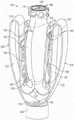
图6示例了假体间隔件装置的另一示例性实施方式。Figure 6 illustrates another exemplary embodiment of a prosthetic spacer device.
图7是图6的假体间隔件装置的侧视图。FIG. 7 is a side view of the prosthetic spacer device of FIG. 6 .
图8A是图6的假体间隔件装置的丝网结构的侧视图。8A is a side view of the wire mesh structure of the prosthetic spacer device of FIG. 6 .
图8B是图6的假体间隔件装置的侧视图,示出了图8A的丝网结构上的覆盖物。8B is a side view of the prosthetic spacer device of FIG. 6 showing a covering over the wire mesh structure of FIG. 8A.
图9示例了假体间隔件装置的另一示例性实施方式。Figure 9 illustrates another exemplary embodiment of a prosthetic spacer device.
图10示例了假体间隔件装置的另一示例性实施方式。Figure 10 illustrates another exemplary embodiment of a prosthetic spacer device.
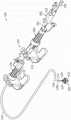
图11示例了包括图6的假体间隔件装置(以部分横截面示出)和递送装置的递送组合件的示例性实施方式。11 illustrates an exemplary embodiment of a delivery assembly including the prosthetic spacer device of FIG. 6 (shown in partial cross-section) and a delivery device.
图12A是被耦接到图11的递送组合件的远端部分的图6的假体间隔件装置的侧视图,其中锚定部和扣件处于打开构型。12A is a side view of the prosthetic spacer device of FIG. 6 coupled to the distal portion of the delivery assembly of FIG. 11 with the anchors and fasteners in an open configuration.
图12B是图11的递送组合件的远端部分的立体图,示出了假体间隔件装置被可释放地耦接至递送装置,其中锚定部和扣件处于闭合构型且没有覆盖物。12B is a perspective view of the distal portion of the delivery assembly of FIG. 11 showing the prosthetic spacer device releasably coupled to the delivery device with the anchors and fasteners in a closed configuration and no covering.
图13是图11的递送组合件的远端部分的立体图,示出了从递送装置释放的假体间隔件装置。13 is a perspective view of the distal portion of the delivery assembly of FIG. 11 showing the prosthetic spacer device released from the delivery device.
图14是图11的递送装置的耦接件的横截面图。14 is a cross-sectional view of a coupling of the delivery device of FIG. 11 .
图15是图11的递送组合件的立体图,其中以部分横截面示出了假体间隔件装置,并且示意性地示出了递送装置的一些部件。15 is a perspective view of the delivery assembly of FIG. 11 showing the prosthetic spacer device in partial cross-section and schematically showing some components of the delivery device.
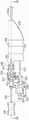
图16是图11的递送装置的轴的平面图。FIG. 16 is a plan view of the shaft of the delivery device of FIG. 11 .
图17是图11的递送装置的近端部分的侧视图。FIG. 17 is a side view of the proximal portion of the delivery device of FIG. 11 .
图18是图11的递送装置的近端部分的沿图17中所示的线18-18截取的横截面图。18 is a cross-sectional view of the proximal portion of the delivery device of FIG. 11 taken along line 18-18 shown in FIG. 17 .
图19是图11的递送装置的近端部分的分解图。FIG. 19 is an exploded view of the proximal portion of the delivery device of FIG. 11 .
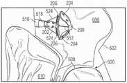
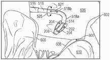
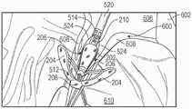
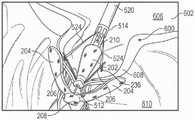
图20至24示例了使用图11的递送组合件的图6的假体间隔件装置的示例性植入程序,以修复心脏的天然二尖瓣(被部分示出)。20-24 illustrate an exemplary implantation procedure of the prosthetic spacer device of FIG. 6 using the delivery assembly of FIG. 11 to repair the native mitral valve of the heart (partially shown).
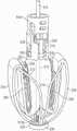
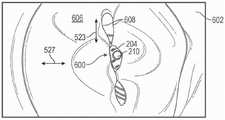
图25示例了从递送组合件释放并允许反流血流通过装置之前,位于二尖瓣的小叶之间的图6的假体间隔件装置。25 illustrates the prosthetic spacer device of FIG. 6 between the leaflets of the mitral valve before being released from the delivery assembly and allowing regurgitation blood flow through the device.
图26示例了从递送组合件释放后并允许反流血液流过装置的图25的假体间隔件装置。26 illustrates the prosthetic spacer device of FIG. 25 after being released from the delivery assembly and allowing reflux blood to flow through the device.
图27A是示例了二尖瓣和左心房的底部的立体图,其中假体间隔件装置被部署在天然小叶之间,并使小叶在心室舒张期间形成双孔口。27A is a perspective view illustrating the mitral valve and the bottom of the left atrium with the prosthetic spacer device deployed between the native leaflets and causing the leaflets to form double orifices during ventricular diastole.
图27B是示例了假体间隔件装置的内皮化后的二尖瓣和左心房底部的立体图。27B is a perspective view illustrating the endothelialized mitral valve and left atrium floor of a prosthetic spacer device.
具体实施方式Detailed ways
本文描述的是主要意图被植入人心脏的二尖瓣、主动脉瓣、三尖瓣或肺动脉瓣膜区域之一的假体间隔件装置的实施方式,以及植入其的装置和方法。假体间隔件装置可用于帮助恢复和/或代替缺陷性天然瓣膜的功能。Described herein are embodiments of a prosthetic spacer device primarily intended to be implanted in one of the mitral, aortic, tricuspid, or pulmonary valve regions of the human heart, as well as devices and methods for implanting the same. Prosthetic spacer devices can be used to help restore and/or replace the function of a defective native valve.
现有的假体间隔件装置通常被配置以在心脏瓣膜,且特别是在二尖瓣中植入时立即减少或防止瓣膜反流。例如,在典型的构型中,假体间隔件装置可包括中心或主体以及一个或多个可移动元件,该一个或多个可移动元件被配置以将天然瓣膜的小叶捕获在元件和主体之间。天然小叶由此可以形成抵靠主体的密封。主体又可以被配置以防止血流通过假体装置,使得在植入时实现二尖瓣反流的急剧减少。这在左心功能未严重退化的患者中可能是有利的。例如,在患者的左心室射血分数(LVEF)大于左心室容量的20%的情况下,在装置的植入时二尖瓣反流的立即减少是可以接受的。如本文所用,“左心室射血分数”和缩写“LVEF”是指在心室收缩期间从左心室被射出的左心室舒张末期容量的分数。Existing prosthetic spacer devices are typically configured to reduce or prevent valve regurgitation immediately upon implantation in a heart valve, and particularly a mitral valve. For example, in a typical configuration, a prosthetic spacer device may include a center or body and one or more moveable elements configured to capture leaflets of the native valve between the element and the body between. The natural leaflet can thus form a seal against the body. The body may in turn be configured to prevent blood flow through the prosthetic device such that a dramatic reduction in mitral regurgitation is achieved upon implantation. This may be beneficial in patients without severe deterioration of left ventricular function. For example, in a patient with a left ventricular ejection fraction (LVEF) greater than 20% of the left ventricular volume, an immediate reduction in mitral regurgitation upon implantation of the device is acceptable. As used herein, "left ventricular ejection fraction" and the abbreviation "LVEF" refer to the fraction of left ventricular end-diastolic volume that is ejected from the left ventricle during ventricular systole.
然而,在LVEF小于20%的患者中,在假体间隔件装置的植入时的二尖瓣反流的急剧减少可能在左心室上导致显著的压力,潜在地导致心力衰竭。例如,根据美国超声心动图学会(American Society of Echocardiography)定义的方法和指南,在分级为3+或4+的中度至重度或重度二尖瓣反流患者中,在分级为MR>3+或MR>4+二尖瓣反流突然减少到分级为MR≤2+的二尖瓣反流可导致心力衰竭和/或死亡。因此,本文提供了假体间隔件装置的实施方式,其在植入时提供了通过装置的显著的急性二尖瓣反流。装置可被配置以在例如几天、几周或几个月的时间内缓慢减少二尖瓣反流。这可以减少与二尖瓣反流突然减少有关的左心室上的压力。如本文所用,参考例如分级为1+、2+、3+或4+的“二尖瓣反流”或“MR”是指由美国超声心动图学会使用评估技术(包括例如,超声心动图、彩色多普勒、荧光检查等)提供的血管造影分级指南(Zoghbiet al,ASE Guidelines and Standards:Recommendationsfor Noninvasive Evaluation of Native Valvular Regurgitation–A Report from theAmerican Society of Echocardiography Developed in Collaboration with theSociety for Cardiovascular Magnetic Resonance,Journal of the American Societyof Echocardiography,April 2017)。However, in patients with LVEF less than 20%, the dramatic reduction in mitral regurgitation upon implantation of a prosthetic spacer device may result in significant pressure on the left ventricle, potentially leading to heart failure. For example, in patients with moderate-to-severe or severe mitral regurgitation with a grade of 3+ or 4+, according to the methods and guidelines defined by the American Society of Echocardiography, in patients with a grade of MR>3+ Or sudden reduction of MR >4+ mitral regurgitation to a grade of MR ≤2+ can lead to heart failure and/or death. Accordingly, provided herein are embodiments of prosthetic spacer devices that, when implanted, provide significant acute mitral regurgitation through the device. The device may be configured to slowly reduce mitral regurgitation over a period of days, weeks, or months, for example. This reduces the pressure on the left ventricle associated with a sudden reduction in mitral regurgitation. As used herein, reference to, for example, "Mitral Regurgitation" or "MR" graded 1+, 2+, 3+, or 4+ refers to the use of assessment techniques by the American Society of Echocardiography (including, for example, echocardiography, Zoghbiet al, ASE Guidelines and Standards: Recommendations for Noninvasive Evaluation of Native Valvular Regurgitation–A Report from the American Society of Echocardiography Developed in Collaboration with the Society for Cardiovascular Magnetic Resonance, Journal of the American Society of Echocardiography, April 2017).
本文所述的假体间隔件装置的实施方式可包括间隔件构件和至少一个锚定部。在某些实施方式中,假体间隔件装置可进一步包括至少一个扣件和至少一个套环(collar)。间隔件构件可以被配置以被定位在天然瓣膜孔口内,以填充不能自然地完全接合的功能失调的天然小叶之间的空间。在某些实例中,间隔件构件可被配置以当装置被植入时允许通过假体装置的急性反流,并逐渐减小通过装置的反流(例如,随着植入物内皮化)。在这样的实例中,间隔件构件可以被配置以提供用于逆行血流(例如,在心室收缩期间从左心室到左心房)通过假体装置的流动路径。其它假体间隔件装置的实例在2018年5月8日提交的美国申请号15/973,892中进一步描述。间隔件构件可以具有各种形状。在一些实施方式中,间隔件构件可具有具有圆形横截面形状的细长圆柱形形状。在其它实施方式中,间隔件构件可以具有卵形横截面形状、月牙形横截面形状或各种其它非圆柱形形状。Embodiments of the prosthetic spacer devices described herein can include a spacer member and at least one anchor. In certain embodiments, the prosthetic spacer device may further include at least one fastener and at least one collar. The spacer member can be configured to be positioned within the native valve orifice to fill the space between the dysfunctional native leaflets that cannot fully coapt naturally. In certain examples, the spacer member can be configured to allow acute regurgitation through the prosthetic device when the device is implanted, and to gradually reduce regurgitation through the device (eg, as the implant endothelializes). In such instances, the spacer member may be configured to provide a flow path for retrograde blood flow (eg, from the left ventricle to the left atrium during ventricular systole) through the prosthetic device. Examples of other prosthetic spacer devices are further described in US Application No. 15/973,892, filed May 8, 2018. The spacer members can have various shapes. In some embodiments, the spacer member may have an elongated cylindrical shape with a circular cross-sectional shape. In other embodiments, the spacer member may have an oval cross-sectional shape, a crescent cross-sectional shape, or various other non-cylindrical shapes.
在被配置以在天然二尖瓣中植入的某些实施方式中,间隔件构件可具有被定位在心脏左心房中或附近的心房端或上端、被定位在心脏左心室中或附近的心室端或下端、以及在天然二尖瓣小叶之间延伸的环形侧面。In certain embodiments configured for implantation in a native mitral valve, the spacer member may have an atrial end or an upper end positioned in or near the left atrium of the heart, a ventricle positioned in or near the left ventricle of the heart The end or the lower end, and the annular side extending between the leaflets of the native mitral valve.
锚定部可被配置以将假体间隔件装置固定到一个或多个天然小叶上,使得间隔件构件被定位在天然小叶之间。锚定部可以被配置以当被植入时被定位在天然小叶后面,使得天然小叶被捕获在锚定部和间隔件构件之间。The anchors may be configured to secure the prosthetic spacer device to the one or more native leaflets such that the spacer member is positioned between the native leaflets. The anchor can be configured to be positioned behind the native leaflet when implanted such that the native leaflet is captured between the anchor and the spacer member.
图1至5示出了假体间隔件装置100及其部件的示例性实施方式。参考图1,假体间隔件装置100可包括间隔件构件102、多个锚定部或桨状物104(例如,在示例的实施方式中为两个中的两个)、多个扣件106(例如,在所示实施方式中为两个)、第一套环108和第二套环110。如图3中最佳所示,锚定部104的第一端部112可被耦接至间隔件构件102的第一端部114并从其延伸,并且锚定部104的第二端部116可被耦接至第一套环108。第二套环110可以被耦接至间隔件构件102的第二端部118。1-5 illustrate exemplary embodiments of a
间隔件构件102和锚定部104可以各种方式被耦接在一起。例如,如示例的实施方式中所示,通过将间隔件构件102和锚定部104一体地形成为单个统一部件,间隔件构件102和锚定部104可以被耦接在一起。例如,如下面参考图8A更详细地描述的,这可以通过由编结或编织材料(如编结或编织的镍钛诺丝)形成间隔件构件102和锚定部104来完成。因此,尽管实际上间隔件构件和锚定部可以由编结和/或编织丝制成,但是出于示例目的,这些特征在图1至3中示意性地被示例为实心构件。在其它实施方式中,间隔件构件102和锚定部104可以通过焊接、紧固件、粘合剂和/或其它用于耦接的手段被耦接在一起。
参考图2,锚定部104可包括由连接(joint)部分124分隔开的第一部分120和第二部分122。以这种方式,锚定部104被配置以类似于腿,因为第一部分120像是腿的上部,第二部分122像是腿的下部,而连接部分124像是腿的膝盖部分。Referring to FIG. 2 , the
锚定部104可被配置以通过沿着在间隔件部件104的第一端部114与第二端部118之间延伸的纵向轴线相对于间隔件部件102轴向地移动第一套环108并因此移动锚定部104而在各种构型之间移动。例如,通过远离间隔件构件102移动第一套环108,使得锚定部104被绷紧,锚定部104可以笔直构型进行定位。处于笔直构型,锚定部106的连接部分124与间隔件构件102的纵向轴线相邻(例如,类似于图20中示出的构型)。The
从笔直构型,可以通过朝向间隔件构件102移动第一套环108,锚定部104可被移动至完全折叠构型(例如,图1)。最初,如图2至3中所示,随着第一套环108朝向间隔件构件102移动,锚定部104在连接部分124处弯曲,并且连接部分124相对于间隔件构件102的纵向轴线径向向外移动以及朝向间隔件构件102的第一端部114轴向地移动。如图1中所示,随着第一套环108继续朝向间隔件构件102移动,连接部分124相对于间隔件构件102的纵向轴线径向向内移动以及朝向间隔件构件102的第二端部118轴向地移动。From the straight configuration, the
在一些实施方式中,当锚定部104处于笔直构型(参见例如图20)时,锚定部104的第一部分120与间隔件构件102之间的角度可以是大约180度,而当锚定部104处于完全折叠构型时,锚定部104的第一部分120和间隔件构件102之间的角度可以是大约0度。锚定部104可以以各种部分地折叠构型被定位,使得锚定部104的第一部分120与间隔件构件102之间的角度可以是大约10-170度或大约45-135度。In some embodiments, the angle between the
配置假体间隔件装置100使得锚定部104可以延伸到笔直或大约笔直的构型(例如,相对于间隔件构件102大约120-180度)可以提供多个优点。例如,这可以减小假体间隔件装置100的径向折绉(crimp)轮廓。通过提供在其中捕获天然小叶的更大开口,还可以使捕获天然小叶变得更容易。另外,相对狭窄、笔直的构型可以防止或减小定位和/或回收假体间隔件装置100到递送装置中时,假体间隔件装置100将缠结在天然解剖部位(例如腱索)中的可能性。Configuring the
再次参考图2,扣件106可包括附接部分126和臂部128。附接部分126可以以各种方式(如用缝线、粘合剂、紧固件(例如,板129)、焊接和/或用于耦接的手段)被耦接至锚定部104的第一部分120。Referring again to FIG. 2 , the
臂部128可相对于附接部分126在打开构型(例如,图2)和闭合构型(图1和3)之间枢转。在一些实施方式中,扣件106可被偏置到闭合构型。在打开构型中,附接部分126和臂部128枢转远离彼此,使得天然小叶可以被定位在附接部分126和臂部128之间。在闭合构型中,附接部分126和臂部128朝向彼此枢转,从而将天然小叶夹持在附接部分126和臂部128之间。The
参考图4至5,附接部分126(图4至5中仅示出一个)可包括一个或多个开口130(例如,在示例的实施方式中为三个)。开口130中的至少一些可用于将附接部分126耦接至锚定部104。例如,缝线和/或紧固件可以延伸通过开口130,以将附接部分126耦接至锚定部104。Referring to Figures 4-5, the attachment portion 126 (only one is shown in Figures 4-5) may include one or more openings 130 (eg, three in the example embodiment). At least some of the
臂部128可包括多个侧梁132,侧梁被间隔开以形成槽134。槽134可被配置以接收附接部分126。臂部128还可包括被耦接至附接部分126的固定端部136和相对固定端部138被布置的自由端部138。The
自由端部138可包括夹持元件,如倒钩140和/或用于摩擦地接合天然小叶组织的其它手段。夹持元件可被配置以接合和/或穿透天然小叶组织,以帮助将天然小叶保持在扣件106的附接部分126和臂部128之间。
自由端部138还可包括眼孔142,其可用于将自由端部138耦接至致动机构,致动机构被配置以使臂部128相对于附接部分126枢转。下面提供了有关将扣件106耦接到致动机构的其它细节。The
在一些实施方式中,扣件106可以由诸如镍钛诺、不锈钢和/或形状记忆聚合物的形状记忆材料形成。在某些实施方式中,在图4中所示的构型中,扣件106可以通过激光切割一片平坦的材料片(例如镍钛诺)来形成,然后以图5中所示的构型定形扣件106。In some embodiments, the
以这种方式定形扣件106可以提供多个优点。例如,扣件106可从定形构型(例如,图5)被压缩到平坦构型(例如,图4),这减小了扣件106的径向折绉轮廓。而且,这也改善了假体间隔件装置100相对于递送装置的导管轴的可追踪性和可回收性,因为当假体间隔件装置100被推进通过导管轴或回收到导管轴中时,倒钩140径向向内指向锚定部104(参见例如图20)。因此,这防止或减小了扣件106卡住或削薄导管轴的可能性。Shaping the
另外,当扣件106处于闭合构型时,以图5中所示的构型定形扣件106可以增加扣件106的夹持力。这是因为臂部128相对于附接部分126被定形至第一位置(例如,图5),这超出了当将扣件106被附接到锚定部104(例如,图3)时臂部128可达到的位置,因为锚定部104防止臂部128进一步朝着定形构型移动。当扣件106被附接到锚定部104并处于闭合构型时,这导致臂部128具有预载荷(即,夹持力大于零)。因此,与以闭合构型定形的扣件相比,以图5构型中定形扣件106可以增加扣件106的夹持力。Additionally, shaping the
可以通过调节臂部128相对于附接部分126的定形的角度来改变扣件106的预载荷的量级。例如,增加臂部128与附接部分126之间的相对角度增加预载荷,和减少臂部128与附接部分126之间的相对角度减少预载荷。The magnitude of the preload of the
在一些实施方式中,第二套环110和/或间隔件构件102可包括止血密封件144,止血密封件144被配置以减少或防止血液流动通过第二套环110和/或间隔件构件102。例如,如图1中所示,在一些实施方式中,止血密封件144可包括多个挠性翼片146。翼片146可被配置以从密封构型枢转到打开构型,以允许递送装置延伸通过第二套环110。当递送装置被移除时,翼片146可被配置以从打开构型返回到密封构型。在其它实施方式中,装置不需要包括这种密封件。In some embodiments, the
图6至8B示出了假体间隔件装置200的示例性实施方式。假体间隔件装置200可以包括间隔件构件202、多个锚定部204、多个扣件206、第一套环208和第二套环210。假体间隔件装置200的这些部件可以被配置以基本上类似于假体间隔件装置100的对应部件。6-8B illustrate an exemplary embodiment of a
假体间隔件装置200还可包括多个锚定部延伸构件212。锚定部延伸构件212可被配置为环件(loops),其具有与第一套环208耦接并从其延伸的第一端部214以及与第一端部214相对布置的第二端部216。锚定部延伸构件212可被配置以比锚定部204在间隔件构件202周围周向地延伸得更多。例如,在一些实施方式中,锚定部延伸构件216中的每个可围绕大约一半的间隔件构件202的圆周延伸(如图7中最佳所示),并且锚定部204可围绕小于一半的间隔件构件202的圆周延伸(如图6中最佳所示)。锚定部延伸构件216还可被配置以侧向地(即,垂直于间隔件构件202的纵向轴线)延伸超过间隔件构件202的外径。The
锚定部延伸构件212还可进一步被配置以使得当假体间隔件装置200处于折叠构型(例如,图6至8)时,锚定部延伸构件212的自由端部216轴向地邻近锚定部204的连接部218并且被径向地在锚定部206的第一部分220和第二部分222之间布置。The
与单独的锚定部204相比,以这种方式配置锚定部延伸构件212提供了增加的表面积。例如,这可以使捕获和固定天然小叶更加容易。增加的表面积还可以将锚定部204和锚定部延伸构件212抵靠天然小叶的夹持力分布在天然小叶的相对较大的表面上,以便进一步保护天然小叶组织。Configuring the
锚定部延伸构件212的增加的表面积还可允许天然小叶被夹持到假体间隔件装置200,使得天然小叶在与假体间隔件装置200相邻的位置处接合在一起,而不是抵靠着间隔件构件202。例如,这可以改善天然小叶的密封,并有助于最终减少二尖瓣反流。The increased surface area of the
如上所述,本文所述的假体间隔件装置的元件(如间隔件构件和/或锚定部构件),可以由多孔结构(如编织和/或编结丝网)制成。图8A示例了这种网结构240的代表性实施方式,其包括多个长丝或丝242。在图8A的实施方式中,丝242可以被编结在一起以形成间隔件构件202的卵形形状,使得网结构在间隔件构件的基本上整个表面周围限定了多个开口244。间隔件构件202还可限定导向到间隔件构件内部中的各自的顶部中心开口246和底部中心开口248。丝242可以被编织在一起以形成锚定部204。As noted above, the elements of the prosthetic spacer devices described herein, such as the spacer member and/or the anchor member, can be made from porous structures such as woven and/or braided wire mesh. FIG. 8A illustrates a representative embodiment of such a
图8B示例了组装的装置200,其包括围绕间隔件构件202和锚定部204布置的覆盖物250。在一些实例中,覆盖物250可以是多孔的,使得覆盖物可渗透血流。例如,在示例的实施方式中,覆盖物250可以是限定了通常以252表明的多个开口的透孔织物或网状物。在某些实例中,覆盖物250可以包括低密度的针织聚酯织物,织物具有例如每英寸60-120横向线圈(course)和每英寸20-60纵行线圈(wale)。覆盖物250还可以包括任意各种编织织物(如丝绒)、非编织织物(如毛毡或纱布),或任意各种多孔或血液可渗透的聚合材料(如膨体聚四氟乙烯(ePTFE)、聚对苯二甲酸乙二酯(PET)、超高分子量聚乙烯(UHMWPE)等)。FIG. 8B illustrates the assembled
在某些实例中,覆盖物250可以是对血液可渗透的,使得血液可以流动通过覆盖物250、通过网结构240、并且进入或离开间隔件构件202的内部。以这种方式,间隔件构件202可以提供通过假体间隔件装置的流动路径,流动路径通常由双头箭头254表明。沿着流动路径254的血液流动方向可以是例如从较高血压的区域到较低血压的区域的方向,如在心室收缩期间从左心室到左心房的方向。在某些实例中,血液也可以流动通过开口246、248。如下面更详细地描述的,这可以在装置被植入时,提供通过假体间隔件装置并且特别是通过间隔件构件202的急性反流血流。In certain examples, the
图9和10示例了可以与上述多孔覆盖物实施方式结合使用的假体间隔件装置的其它实施方式。图9示出了假体间隔件装置300的示例性实施方式,其包括呈金属框架形式的环形间隔件构件302以及从间隔件构件302延伸的锚定部304。每个锚定部304的端部可以通过各自的套筒306被耦接到间隔件构件302的各自的支柱,套筒306可以围绕锚定部306的端部和间隔件构件302的支柱进行折绉。安装在间隔件构件302的框架上的可以是一个或多个倒钩或突出部308。突出部308的自由端可包括各种形状,包括圆形的、尖头的、有倒钩的等。突出部308可以借助于锚定部304抵靠天然小叶施加保持力,锚定部304被成形为将天然小叶在锚定部304的自由端下方的区域中向内推动到间隔件构件302中。如上所述,装置300可包括多孔覆盖物,以便允许血液流动通过间隔件构件302。Figures 9 and 10 illustrate other embodiments of prosthetic spacer devices that may be used in conjunction with the porous covering embodiments described above. FIG. 9 shows an exemplary embodiment of a
图10示出了假体间隔件装置400的另一实施方式。假体间隔件装置400可包括与假体间隔件装置300类似的呈金属框架形式的环形间隔件构件402和从间隔件构件402延伸的锚定部404。假体间隔件装置400的锚定部404可被配置以类似于假体间隔件装置300的锚定部304,除了在每个锚定部404的自由端处的弯曲包括比锚定部304更大的半径。这样,与锚定部304相比,锚定部404覆盖间隔件构件402的相对较大的部分。例如,这可以将锚定部404抵靠天然小叶的夹持力分布在天然小叶的相对较大的表面上,以便进一步保护然小叶组织。这也可以改善密封,因为天然小叶被夹持抵靠假体间隔件装置400,使得天然小叶在与假体间隔件装置400相邻的位置处接合在一起,而不是抵靠着间隔件构件402。FIG. 10 shows another embodiment of a
同样,安装在间隔件构件402的框架上的可以是一个或多个倒钩或突出部406。突出部406的自由端可包括止动件408,止动件408被配置以限制可以接合和/或穿透天然小叶的突出部406的程度。如上所述,装置400还可包括多孔覆盖物,以允许血流通过间隔件构件402。Likewise, mounted on the frame of the
例如,在美国专利申请公开号2016/0331523中可以找到关于假体间隔件装置的其它细节。Additional details regarding prosthetic spacer devices can be found, for example, in US Patent Application Publication No. 2016/0331523.
本文所述的假体间隔件装置可被耦接至递送装置以形成递送组合件。递送装置可用于将假体间隔件装置经皮递送、定位和/或固定在患者的天然心脏瓣膜区域内。图11至27B示出了示例性递送组合件500及其部件。参考图11,递送组合件500可包括假体间隔件装置200和递送装置502。递送装置502可包括多个导管和导管稳定器。例如,在示例的实施方式中,递送装置502包括第一导管504、第二导管506、第三导管508和导管稳定器510。第二导管506同轴地延伸通过第一导管504,并且第三导管508同轴地延伸通过第一导管和第二导管504,506。如下文进一步描述的,假体间隔件装置200可以被可释放地耦接到递送装置502的第三导管508的远端部分。The prosthetic spacer devices described herein can be coupled to a delivery device to form a delivery assembly. The delivery device can be used to percutaneously deliver, position and/or secure a prosthetic spacer device within the region of a patient's native heart valve. 11-27B illustrate an
在示例的实施方式中,递送组合件500被配置为例如用于经由经中隔递送方式将假体间隔件装置200植入到天然二尖瓣中。在其它实施方式中,递送组合件500可以被配置用于将假体间隔件装置200植入到人心脏的主动脉、三尖瓣或肺动脉瓣区域中。而且,递送组合件500可被配置用于各种递送方法,包括经中隔、经主动脉、经心室等。In an example embodiment,
图12A和图12B示例了被耦接至递送装置的远端的假体间隔件装置200。在图12A中,间隔件装置200被示出处于打开构型并且包括覆盖物250。在图12B和13中,示出了不带有覆盖物250的间隔件装置200,其中为了示例目的被示意性地示例为实心构件的间隔件构件202和锚定部构件204。参考图13所示,假体间隔件装置200的第一或远端套环208可包括钻孔226。在一些实施方式中,如图12B中最佳所示,钻孔226可包括内螺纹,所述内螺纹被配置以可释放地接合递送装置502的致动轴512的对应外螺纹。12A and 12B illustrate a
再次参考图13,假体间隔件装置200的第二或近侧套环210可包括与远侧套环208的钻孔226轴向地对准的中心开口228。如图12B中最佳所示,近侧套环210的中心开口228可被配置以可滑动地接收递送装置502的致动轴512。在一些实施方式中,近侧套环210和/或间隔件构件202可以具有密封构件(未示出,但是参见例如图1中示出的密封构件144),所述密封构件被配置以在致动轴512从中心开口228被抽出时密封中心开口228。Referring again to FIG. 13 , the second or
如图13中最佳所示,近侧套环210还可包括多个凸台(bosses)或突出部230和多个引导开口232。凸台230可以径向向外延伸,并且可以相对于引导开口232周向地偏移(例如90度)。引导开口232可从中心开口228径向向外被布置。如图12中所示,近侧套环210的突出部230和引导开口232可被配置以可释放地接合递送装置502的耦接件514。As best shown in FIG. 13 , the
再次参考图11并且如上所提到的,递送装置502可以包括第一导管504和第二导管506。第一导管504和第二导管506可用于例如进入植入位置(例如,心脏的天然二尖瓣区域)和/或将第三导管508定位在植入位置。Referring again to FIG. 11 and as mentioned above, the
第一导管504和第二导管506可分别包括第一鞘516和第二鞘518。导管504、506可以被配置使得鞘516、518是可操纵的。关于第一导管504的另外的细节可以在例如美国专利申请公开号2016/0155987中找到。关于第二导管506的另外的细节可以在例如美国公开号2018/0126124中找到。The
仍然参考图11,如上所提到的,递送装置502还可包括第三导管508。第三导管508可以例如用于在植入位置处递送、操控、定位和/或部署假体间隔件装置200。Still referring to FIG. 11 , as mentioned above, the
参考图15,第三导管508可包括致动轴或内轴512、耦接件514、外轴520、手柄522(示意性地示出)、和扣件控制构件524。外轴520的近端部分520a可以被耦接到手柄522并从手柄522向远侧延伸,并且外轴520的远端部分520b可以被耦接到耦接件514。致动轴512的近端部分512a可被耦接至致动旋钮526。致动轴512可以从旋钮526(示意性地示出)通过手柄522、通过外轴520、以及通过耦接件514向远侧延伸。致动轴512可以是相对于外轴520和手柄522可移动的(例如轴向地和/或旋转地)。扣件控制构件524可延伸通过手柄522和外轴520并相对于手柄522和外轴520轴向地可移动。扣件控制构件524也可以相对于致动轴512轴向地可移动。在一些实施方式中,扣件控制构件524可以被配置为缝线,并且可以通过扣件206中的开口234被成环。在其它实施方式中,扣件控制构件524可包括套筒1102,连接构件和释放构件延伸通过套筒1102,如图12A中所示的并在上面提出的美国申请号15/973,892中进一步描述的。Referring to FIG. 15 , the
如图12A、图12B和图13中最佳所示,第三导管508的致动轴512被可释放地耦接至假体间隔件装置200的远侧套环208。例如,在一些实施方式中,致动轴512的远端部分512b可包括外螺纹,外螺纹被配置以可释放地接合假体间隔件装置200的钻孔226的内螺纹。这样,使致动轴512相对于假体间隔件装置200的远侧套环208在第一方向中(例如,顺时针)旋转,将致动轴512可释放地固定到远侧套环208。使致动轴512相对于假体间隔件装置200的远侧套环208在第二方向中(例如,逆时针)旋转,将致动轴512从远侧套环208释放。As best shown in FIGS. 12A , 12B and 13 , the
现在参考图12A至14,第三导管508的耦接件514可以被可释放地耦接到假体间隔件装置200的近侧套环210。例如,在一些实施方式中,耦接件514可包括多个挠性臂528和多个稳定器构件530。挠性臂528可以包括孔532、端口533(图13)和眼孔534(图14)。Referring now to FIGS. 12A-14 , the
挠性臂528可被配置以在第一或释放构型(图13)和第二或耦接构型(图12B和14)之间枢转。在第一构型中,挠性臂528相对于稳定器构件530径向向外延伸。如图14中最佳所示,在第二构型中,挠性臂530平行于稳定器构件530轴向地延伸,并且眼孔534径向地重叠。挠性臂528可以被配置(例如,定形)以便被偏置到第一构型。The
通过将耦接件514的稳定器构件530插入到假体间隔件装置200的引导开口232中,假体间隔件装置200可以被可释放地耦接到耦接件514。然后,耦接件514的挠性臂528可以从第一构型径向向内枢转到第二构型,使得假体间隔件装置200的突出部230径向地延伸到挠性臂528的孔532中。通过将驱动轴512的远端部分512b插入通过眼孔534的开口536,挠性臂528可以第二构型进行保持,这防止了挠性臂528从第二构型径向向外枢转至第一构型,从而将假体间隔件装置200可释放地耦接到耦接件514。The
可通过相对于耦接件514向近侧缩回致动轴512将假体间隔件装置200从耦接件514释放,使得致动轴512的远端部分512b从眼孔534的开口536抽出。这允许挠性臂528从第二构型径向向外枢转至第一构型,其将假体间隔件装置200的突出部230从挠性臂528的孔532抽出。在挠性臂528被释放期间和之后,稳定器构件530可保持被插入到假体间隔件装置200的引导开口232中。例如,这可以防止假体间隔件装置200在挠性臂528被释放时移动(例如,移位和/或摇摆)。然后,通过相对于假体间隔件装置200向近侧缩回耦接件514,稳定器构件530可以从假体间隔件装置200的引导开口232被抽出,从而从耦接件514中释放假体间隔件装置200。
参考图15,第三导管508的外轴520可以是在耦接手柄522的近端部分520a和耦接至耦接件514的远端部分520b之间轴向延伸的细长轴。外轴520还可包括被布置在近端部分520a和远端部分520b之间的中间部分520c。Referring to FIG. 15 , the
参考图16,外轴520可包括多个轴向延伸的内腔,包括致动轴内腔538和多个控制构件内腔540(例如,在示例的实施方式中为四个)。在一些实施方式中,外轴520可包括比四个控制构件内腔540更多个(例如六个)或更少个(例如两个)。16, the
致动轴内腔538可被配置以接收致动轴512,并且控制构件内腔540可被配置以接收一个或多个扣件控制构件524。内腔538、540也可被配置使得致动轴512和扣件控制构件524可相对于各自内腔538、540是可移动的(例如,轴向地和/或旋转地)。在特定实施方式中,内腔538、540可包括被配置以减小在内腔538、540内的摩擦的衬里或涂层。例如,内腔538、540可以包括包含PTFE的衬里。
仍然参考图15至16,外轴520可以由包括金属和聚合物的各种材料形成。例如,在一个特定实施方式中,近端部分520a可包括不锈钢,以及远侧部分520b和中间部分520c可包括PEBA(例如,
外轴520可以包括从内腔538、540径向向外布置的一个或多个线圈部分542。例如,在一个特定实施方式中,外轴520可包括第一线圈542a、第二线圈542b和第三线圈542c。第一线圈542a可以是径向最外侧的线圈,第三线圈542c可以是径向最内侧的线圈,以及第二线圈542b可以被径向地布置在第一线圈542a和第三线圈542c之间。The
线圈部分542可以包括各种材料和/或构型。例如,线圈部分542可以由不锈钢形成。在一个特定实施方式中,第一线圈542a和第三线圈542c包括以左旋构型卷绕的不锈钢线圈,并且第二线圈542b包括以右旋构型卷绕的不锈钢线圈。
线圈部分542还可包括各种螺距(pitches)。一个或多个线圈542的螺距可以与一个或多个其它线圈542的螺距相同或不同。在一个特定实施方式中,第一线圈542a和第二线圈542b可具有第一螺距(例如0.74英寸),而第三线圈可包括第二螺距(例如0.14英寸)。The
外轴520还可包括从第三线圈542c径向向内布置的束缚层544。束缚层544可以由包括聚合物(如PEBA(例如,
如图17至19所示,第三导管508的手柄522可包括壳体546、致动锁定机构548、扣件控制机构550、和冲洗机构552。参考图17,壳体546的远端部分可以被耦接至外轴520的近端部分520a。致动锁定机构548、扣件控制机构550和冲洗机构552可以被耦接到壳体546的近端。致动锁定机构548可被配置以选择性地锁定致动轴512相对于壳体546和外轴520的位置。扣件控制机构550还可以被耦接到扣件控制构件524的近端部分,并且可以被配置以相对于手柄522固定扣件控制构件524并且相对于外轴520和致动轴512移动扣件控制构件524。冲洗机构552可以被配置以在将外轴520插入患者的脉管系统之前(例如,用盐溶液)冲洗外轴520。As shown in FIGS. 17-19 , the
如图18至19中最佳所示,手柄522的壳体546可包括主体554和耦接至主体554的远端部分的鼻部556。主体554和鼻部556可以以各种方式(包括紧固件558和/或销560(例如,如在示例的实施方式中所示)、粘合剂和/或其它耦接手段)耦接在一起。壳体546可以由各种材料(包括聚合物(例如,聚碳酸酯))形成。As best shown in FIGS. 18-19 , the
壳体546的主体554可包括多个内腔,包括致动轴内腔562、控制构件内腔564(图19)以及流体地连接至致动轴内腔562的冲洗内腔566(图18)。如图19中最佳所示,主体554还可包括多个管(例如,海波管),其包括分别至少部分地被布置在致动轴内腔562和控制构件内腔564中的致动管568和控制构件管570。管568、570分别相对于内腔562、564可以是可轴向移动的(例如,可滑动的)。The
致动管568的近端可以从主体554向近侧延伸,并且可以被耦接至旋钮526以及致动轴512的近端部分512a。控制构件管570的近端可以从主体554向近侧延伸,并且可以被耦接至扣件控制机构550和扣件控制构件524。The proximal end of the
管568、570的远端可包括凸缘572、574,凸缘572、574被配置以与止动件接合以限制管568、570相对于壳体546的轴向移动。例如,凸缘572、574可被配置以接触主体554的各自表面(例如,唇),以防止管568、570分别从内腔562、564的近端完全抽出。The distal ends of the
致动管568可被配置以接收并被耦接至致动轴512的近端部分。如下文进一步描述的,控制构件管570可以被配置以接收扣件控制机构550的部分。管568、570可以由各种材料(包括聚合物和金属(例如,不锈钢))形成。The
在一些实施方式中,主体554可以包括多个密封构件576(例如,O形环),其被配置以防止或减少通过内腔以及围绕轴和/或管的血液渗漏。密封构件可以例如通过紧固件578(例如,空心锁或插口紧定螺钉(socket-jam set screws))相对于主体554进行固定。In some embodiments, the
如图19中最佳所示,壳体546的鼻部556可包括多个内腔,其包括致动轴内腔580和控制构件内腔582。鼻部556的致动轴内腔580可与主体554的致动轴内腔562一起同轴地延伸。鼻部556的控制构件内腔582的近端可以在鼻部556的近端处与主体554的控制构件内腔564对准(即,内腔582、564在同一平面内)。控制构件内腔582可从它们的近端以一定角度(即,相对于主体554的控制构件内腔564)朝向彼此延伸,并且控制构件内腔582的远端可在靠近鼻部556的远端的位置处与鼻部556的致动轴内腔580相交。换句话说,内腔582的近端在平行于导管的纵向轴线的第一平面(即,主体554的控制构件内腔564的平面)中,并且内腔582的远端在平行于导管的纵向轴线的第二平面(即,主体554的致动轴内腔562的平面)中。As best shown in FIG. 19 , the
如图18中最佳所示,鼻部556的致动轴内腔580可被配置以接收外轴520的近端部分。外轴520的近端部分可以以各种方式(如用粘合剂、紧固件、摩擦配合和/或其它耦接手段)被耦接至鼻部556。As best shown in FIG. 18 , the
仍然参考图18,手柄522的致动锁定机构548可以被耦接至壳体546的主体554的近端部分并被耦接至致动管568。致动锁定机构548可被配置以选择性地控制在致动管568和壳体546之间的相对移动。继而,这选择性地控制在致动轴512(其被耦接至致动管568)与外轴520(其被耦接至壳体546的鼻部556)之间的相对移动。Still referring to FIG. 18 , the
在一些实施方式中,致动锁定机构548可包括锁定构型和释放构型,锁定构型防止在致动管568和壳体546之间的相对移动,释放构型允许在致动管568和壳体546之间的相对移动。在一些实施方式中,致动锁定机构548可被配置以包括一种或多种中间构型(即,除了锁定和释放构型之外),其允许在致动管568和壳体546之间的相对移动,但是引起相对移动所需的力大于当致动锁定机构处于释放构型时的力。In some embodiments, the
如示例的实施方式的图18中所示,致动锁定机构548可包括锁(例如,Tuohy-Borst适配器)584和耦接件(例如,鲁尔母固定耦接件(femal luer coupler))586。耦接件586可以被附接到锁584的远端,并且被耦接到壳体546的主体554的近端。致动管568可以同轴地延伸通过锁584和耦接件586。这样,在第一方向(例如,顺时针)旋转锁584的旋钮588可以增加锁584在致动管568上的摩擦接合,因此使得致动管568与壳体546之间的相对移动更加困难或完全阻止它。在第二方向(例如,逆时针)旋转锁584的旋钮588可减小锁584在致动管568上的摩擦接合,因此使得致动管568与壳体546之间的相对移动更容易。As shown in FIG. 18 of an example embodiment, the
在其它实施方式中,致动锁定机构548可包括被配置用于防止在致动管568和壳体546之间的相对移动的其它构型。例如,致动锁定机构548可包括被配置以类似于旋塞阀的锁,其中阀的柱塞部分选择性地接合致动管568。In other embodiments, the
在一些实施方式中,致动锁定机构548可包括释放构件(例如,紧定螺钉或销)。释放构件可以延伸到壳体546中并且可以选择性地接合致动管568。当释放构件与致动管568接合时(例如,通过将释放构件插入壳体546中并与致动管568接触),释放构件可以例如防止致动管568并因此防止致动轴512从它们各自的内腔568、580中完全抽出(例如,当致动锚定部204时)。当释放构件从致动管568被释放时(例如,通过将其从壳体546中抽出和/或使其移动脱离与致动管546的接触),致动管568以及因此致动轴512可从它们各自的内腔568、580完全抽出(例如,当从递送装置502释放假体间隔件装置200时)。In some embodiments, the
扣件控制机构550可包括致动器构件590和一个或多个锁定构件592(例如,在示例的实施方式中为两个)。如图18中最佳所示,致动器构件590的远端部分可被耦接至控制构件管570,控制构件管570从壳体546的主体554的近端延伸。锁定构件592可以被耦接至致动器构件590的近端部分。The
如示例的实施方式中所示,致动器构件590可以可选地包括第一侧部594和通过连接销598选择性地耦接到第一侧部594的第二侧部596。致动器构件590可被配置使得当将连接销598被插入通过第一侧部594和第二侧部596时第一侧部594和第二侧部596一起移动。当连接销598被抽出时,第一侧部594和第二侧部596可相对于彼此移动。这可以允许扣件控制构件524(其通过锁定构件592被可释放地耦接到第一侧部594和第二侧部596)单独地被致动。As shown in the example embodiment, the
第一侧部594和第二侧部596之间的连接可被配置使得当连接销598被抽出时,第一侧部594和第二侧部596可相对于彼此轴向地(即,向近侧和向远侧)移动,但不能相对于彼此旋转地移动。例如,这可以通过配置带有键槽或凹槽的第一侧部594并配置带有键突出部或舌(其与第一侧部594的键槽或凹槽对应)的第二侧部594来完成。例如,这可以防止或减小扣件控制构件524相对于外轴520扭曲的可能性。The connection between the
第一侧部594和第二侧部596可包括轴向延伸的内腔501。内腔501的远端可以被配置以接收控制构件管570的近端部分。内腔501的近端可以被配置以接收锁定构件592的部分。如上所述,扣件控制构件524的近端部分延伸通过各自的锁定构件592。The
锁定构件592可以被配置以选择性地控制扣件控制构件524与致动器构件590的各自的第一侧部594或第二侧部596之间的相对移动。锁定构件592可包括锁定构型和释放构型,锁定构型防止扣件控制构件524与各自的第一侧部594或第二侧部596之间的相对移动,释放构型允许扣件控制构件524与各自的第一侧部594和第二侧部594之间的相对移动。在一些实施方式中,锁定构件592还可以包括一个或多个中间构型(即,除了锁定和释放构型之外),其允许扣件控制构件524与各自的第一侧部594或第二侧部596之间的相对移动,但是引起相对移动所需的力大于当锁定构件592处于释放构型时的力。The locking
如示例的实施方式中所示,锁定构件592可以被配置以类似于旋塞阀。因此,在第一方向(例如,顺时针)旋转旋钮503可以增加在扣件控制构件524上的锁定构件592之间的摩擦接合,并使在扣件控制构件524与各自的第一侧部594或第二侧部596之间的相对移动更困难或完全防止它。在第二方向(例如,逆时针)旋转旋钮503可以减小在扣件控制构件524上的锁定构件592之间的摩擦接合,并使扣件控制构件524与各自的第一侧部594或第二侧部596之间的相对移动更容易。在其它实施方式中,锁定构件592可以包括其它构型,其它构型被配置用于防止在扣件控制构件524上的锁定构件592之间的相对移动。As shown in the example embodiment, the locking
冲洗机构552可包括冲洗管505和阀507(例如旋塞阀)。冲洗管505的远端可被耦接至冲洗内腔566并与冲洗内腔566流体连通,并因此与主体554的致动轴内腔562流体连通。冲洗管505的近端可以被耦接到阀507。以这种方式,冲洗机构552可被配置用于在将外轴520插入患者的脉管系统之前(例如,用盐溶液)冲洗外轴520。The
如下文进一步描述的,扣件控制构件524可被配置以操控扣件206的构型。如图15中最佳所示,每个扣件控制构件524可被配置为缝线(例如,丝或线)环件。扣件控制构件524的近端部分可以从扣件控制机构550的近端部分向近侧延伸,并且可以被可释放地耦接到扣件控制机构550的锁定构件592。As described further below, the
扣件控制构件524可以从锁定构件592形成环件,环件向远侧延伸通过扣件控制机构550的内腔501、通过控制构件管570、手柄522的控制构件内腔564、582、以及通过外轴520的控制构件内腔540。扣件控制构件524可从内腔540径向向外延伸,例如,通过耦接件514的端口533(图13)。然后,扣件控制构件524可以延伸通过扣件206的开口234(例如,类似于假体间隔件装置100的开口142)。然后,扣件控制构件524可向近侧延伸回到耦接件514、径向向内通过耦接件514的端口533、以及然后向近侧通过外轴520和手柄522、并延伸到扣件控制机构550的锁定构件592。The
在图15中,示出了扣件控制构件524是松弛的,并且扣件206是部分打开的,以便示例扣件控制构件524延伸通过扣件206的开口234。然而,一般当扣件控制构件524是松弛的时,扣件206将处于闭合构型。In FIG. 15 , the
如示例的实施方式中所示,每个扣件控制构件524可延伸通过外轴520的多个控制构件内腔540。例如,每个扣件控制构件524可以通过两个内腔540进行成环。在其它实施方式中,每个扣件控制构件524可被布置在单个控制构件内腔540中。在其它实施方式中,多个扣件控制构件524可被布置在单个控制构件内腔540中。As shown in the example embodiment, each
在扣件控制构件524被耦接至扣件206的情况下,扣件控制机构550可用于在打开和闭合构型之间致动扣件206。可以通过相对于旋钮526和壳体546向近侧移动致动器构件590来打开扣件206。这增加扣件控制构件524的张力,并使扣件206从闭合构型移动到打开构型。可以通过相对于旋钮526和壳体546向远侧移动致动器构件590来闭合扣件206。这减小扣件控制构件524上的张力,并且允许扣件206从打开构型移动到闭合构型。可以通过移除连接销598并使第一侧部594或第二侧部596相对于彼此、旋钮526和壳体546移动,来单独地致动扣件206。With the
如图17至18中最佳所示,当手柄522被组装时,致动轴512可从旋钮526向远侧延伸通过致动管568、通过壳体546的致动内腔562、580、通过外轴520的致动轴内腔538、并通过耦接件514。17-18, when the
图20至27示出了递送组合件500,所述递送组合件500被使用以例如使用经中隔递送方式将假体间隔件装置200植入心脏602的天然二尖瓣600中。尽管未示出,但是可以通过引导器鞘将引导丝插入患者的脉管系统(例如股静脉)。引导丝可以被推进通过股静脉,通过下腔静脉,进入右心房中,通过房间隔(例如经由卵圆窝),并进入左心房606。如图20中最佳所示,第一导管504的第一鞘516可在引导丝上被推进,使得第一鞘516的远端部分被布置在左心房606中。20-27 illustrate a
在假体间隔件装置200被耦接到第三导管508(例如,如图12A和12B中所示)并且被配置以处于径向压缩的递送构型的情况下,假体间隔件装置200可被装载到第二导管506的第二鞘518中,第二鞘518保持处于递送构型的假体间隔件装置200。以这种方式,第二鞘518的远端部分用作用于假体植入物200的递送胶囊。在一些实施方式中,径向压缩的递送构型可以是轴向伸长的构型(例如,类似于图20中所示的构型)。在其它实施方式中,径向压缩的递送构型可以是轴向缩短的构型(例如,类似于图22中所示的构型)。然后,第二导管506伴随假体间隔件装置200和第三导管508可一起被推进通过第一导管504,直到鞘518的远端部分从第一鞘516的远端部分向外延伸并被布置在左心房606中,如图20所示。With the
如图20所示,通过使第三导管508的外轴520和致动轴512相对于第二鞘518向远侧推进和/或相对于外轴520和致动轴512缩回第二鞘518,因此迫使锚定部204离开第二鞘518,可以将假体间隔件装置200从第二鞘518暴露。一旦从第二鞘518暴露,就可以通过相对于第三导管508的外轴520缩回第三导管508的致动轴512和/或通过相对于致动轴512推进外轴520来折叠锚定部204,导致锚定部204从图20中所示的径向压缩的构型弯曲至图21中所示的部分折叠状态,然后弯曲至图22中所示的完全折叠构型。例如,这可以通过以下方式完成:将致动锁定机构548以释放构型放置(例如,通过相对于手柄522逆时针旋转旋钮588),以及然后相对于壳体546向近侧移动旋钮526。在这个程序中的任何时候,医师可以通过致动致动锁定机构548来锁定致动轴512和外轴520的相对位置,并因此锁定锚定部204的位置。As shown in FIG. 20 , by advancing the
然后,如图22中所示,可以通过操控(例如,操纵和/或弯曲)第二导管506的第二鞘518,假体间隔件装置200可以被相对于天然二尖瓣600同轴定位。假体间隔件装置200也可以相对于天然二尖瓣600(例如,通过旋转壳体546)旋转,使得锚定部204与二尖瓣600的天然小叶608对准。第二鞘518的曲率可以(例如,用操纵机构)调节,使得远侧可操纵区段518a相对于从可操纵区段518a向近侧延伸的区段518b以约90度角延伸。有利地,这将可操纵的远侧区段518a和假体间隔件装置200沿着基本上垂直于由天然二尖瓣限定的平面的轴线定位。以另一方式陈述,通过可操纵的远侧区段518a和假体间隔件装置200延伸的轴线与天然二尖瓣的流动路径同轴或基本上平行。Then, as shown in FIG. 22 , the
相对于第一导管504的第一鞘516和左心房606缩回或推进第二导管506的第二鞘518和第三导管508的外轴520(例如,在图22中沿箭头521所示的方向)使第三导管508的外轴520和假体间隔件装置200相对于天然小叶608在内侧和外侧方向(例如,在图27A中箭头523所示的方向)移动。当第二鞘518和外轴520被推进和/或缩回时,假体间隔件装置200相对于天然二尖瓣在上/下方向上(例如,在图22中所示取向的向上/向下)的定位保持至少基本上恒定,和/或由于如上所述的第二导管506的操纵机构的构型,第二鞘518不“绕绞(whip)”。相对于第一导管504的第一鞘516和左心房606旋转(这也可被称为“扭转(torquing)”)第二导管506的第二鞘518(例如,在图22中箭头525所示的方向上),使第三导管508的外轴520和假体间隔件装置200在前/后方向上(例如,在图27A中箭头527所示的方向上)枢转。假体间隔件装置200还可相对于天然二尖瓣600(例如,通过旋转壳体546)旋转,以使锚定部204与天然二尖瓣600的天然小叶608对准。可以通过相对于第二导管506的第二鞘缩回/推进第三导管508的外轴520来调节假体间隔件装置200相对于天然二尖瓣在上/下方向上(例如,在图22中所示取向的向上/向下)的定位。因此,所公开的递送装置的一个优点是,可以在三个方向(即,内侧/外侧、前/后、和上/下方向)上独立地调节假体间隔件装置的定位。例如,致动递送装置使得假体间隔件装置在内侧/外侧方向上移动不会影响假体间隔件装置在前后方向或上下方向上的定位。因此,递送装置502的三向和/或独立的可操作性允许执业医生以相对较快和/或容易的方式将假体间隔件装置200准确和/或精确地定位在相对于天然小叶的期望植入位置处(例如,在天然小叶的接合线的中心附近的A2/P2位置处)。Retract or advance the
然后,通过相对于壳体546向远侧移动旋钮526,假体间隔件装置200的锚定部204可被部分地打开(即,相对于间隔件构件202径向向外移动)到图23中所示的构型。然后,假体间隔件装置200可被推进通过天然二尖瓣600的瓣环,并至少部分地进入左心室610中。然后假体间隔件装置200被部分地缩回,使得锚定部204被定位在小叶608的心室部分的后面(例如,在A2/P2位置),并且间隔件构件202被布置在小叶608的心房侧。可替代地,假体间隔件装置200可以以完全折叠构型(如图22中所示)被推进通过天然瓣膜,其后锚定部204可被打开。Then, by moving
在这种构型中,通过用扣件206捕获天然小叶可将天然小叶608相对于锚定部204进行固定。通过致动致动器构件590,天然小叶608可同时或分开地被捕获。例如,图24示出了单独的小叶捕获。这可以通过从致动器构件590移除销598并且使第一侧部594或第二侧部596相对于彼此、旋钮526和壳体546移动来完成。相对于旋钮526和壳体546向远侧移动第一侧部594或第二侧部596,使天然小叶608上的扣件206闭合(例如,如图24中示例的由左扣件206所示的)。相对于旋钮526和壳体546向近侧移动第一侧部594或第二侧部596,使扣件206打开(例如,如图24中示例的由右扣件206所示的)。在扣件206被闭合时,医师可以重新打开扣件206以调节扣件206的定位。In this configuration, the
随着扣件206重新打开,扣件206最初朝着间隔件构件202径向向内移动(例如,如图24中的右扣件206所示),直到扣件206接触间隔件构件202(例如,如图23中所示)。在一些情况下,随着扣件206被重新打开,扣件206的倒钩236可保持天然小叶608并朝向间隔件构件202牵拉天然小叶608。在扣件206接触间隔件构件202时,进一步张紧扣件控制构件524使扣件206相对于间隔件构件202稍微向近侧移动(并使锚定部204稍微展开)。扣件206的近侧移动可以例如从天然小叶608抽出倒钩236,这可以促进假体间隔件装置200的重新定位和/或回收。As the
如图25中所示,在将两个天然小叶608固定在扣件206内的情况下,医师可相对于壳体546向近侧移动旋钮526。这将锚定部204和因此天然小叶608抵靠间隔件构件202径向向内牵拉,如图25中所示。然后,医师可以观察定位和/或通过间隔件装置进入左心房的反流量。As shown in FIG. 25 , with the two
例如,图25示例了在从递送装置释放装置之前在二尖瓣600中处于部署构型的假体间隔件装置200。随着左心室610收缩,血液可以沿着流动路径254通过间隔件构件202从左心室610向左心房606反流地流动。在一些实施方式中,小叶608可形成抵靠间隔件构件202的密封,使得主要的急性反流通过间隔件构件202。如果需要重新定位或移除,则医师可以重新打开锚定部204和/或扣件206。For example, Figure 25 illustrates
一旦实现期望的定位和/或急性反流,医生就可以从递送装置502释放假体间隔件装置200。通过从锁定构件592释放扣件控制构件524并且从扣件206的开口234松脱扣件控制构件524,可以从递送装置502释放扣件206。通过使旋钮526相对于壳体546在第二方向上旋转,使得致动轴512从钻孔226抽出,假体间隔件装置200的远侧套环208可从递送装置502释放。然后,通过相对于壳体524向近侧牵拉旋钮526,致动轴512可通过假体间隔件装置200向近侧被缩回。通过使致动轴512相对于耦接件514向近侧缩回,使得致动轴512的远端部分从耦接件514的眼孔534抽出,假体间隔件装置200的近侧套环210可从递送装置502被释放。这允许耦接件514的挠性臂528远离近侧套环210的突出部230径向向外移动。然后,通过向近侧牵拉壳体546,耦接件514的稳定器构件530可以从近侧套环210的引导开口232被抽出,从而如图26中所示从递送装置502释放假体间隔件装置200。Once the desired positioning and/or acute reflux is achieved, the physician may release the
然后,第三导管308的轴512、520可以向近侧被缩回到第二导管306的第二鞘518中,并且第二导管506的第二鞘518可以向近侧被缩回到第一导管504的第一鞘516中。然后可以将导管504、506、508向近侧缩回并从患者的脉管系统移除。Then, the
如图27A中所示,在一些实施方式中,在假体间隔件装置200被植入到A2/P2位置的情况下,天然二尖瓣600可以在心室舒张期间包括双孔口。在心室收缩期间,天然小叶608可接合在一起和/或抵靠假体间隔件装置200(例如,以防止或减少通过小叶的二尖瓣反流)。然而,假体间隔件装置200可在装置被植入时提供用于急性反流或逆行血流通过间隔件构件202。如本文所用,短语“在植入时”、“在部署时”等是指天然小叶在锚定部构件和间隔件构件之间被捕获,使得假体间隔件装置准备从递送装置释放的时间,以及在从递送装置中释放假体间隔件装置之后的分钟或小时(例如,长达12小时)。As shown in Figure 27A, in some embodiments, with the
例如,处于某些构型时,在假体间隔件装置被部署时通过间隔件构件202的反流血液的量可以等同于具有至少MR>2+、至少MR>3、或至少MR>4+的血管造影分级的二尖瓣反流。在其它实例中,在假体间隔件装置被部署时通过间隔件构件202的反流血流的量可以与装置被植入之前通过天然二尖瓣的反流血流的量相同或几乎相同。For example, in certain configurations, the amount of refluxed blood through the
例如,患有中度至重度二尖瓣反流(例如,具有MR>3+的血管造影分级)的患者可能会在假体间隔件装置的植入之前的每个心动周期中具有相当于其左心室心搏量的30%、40%、或多于40%的反流血流。如本文所用,术语“左心室心搏量”是指左心室的舒张末期容量与左心室的收缩末期容量之间的差。在成年人中,左心室舒张末期容量可能是从120mL至165mL、130mL至155mL、或140mL至150mL。在某些实例中,年龄在20至79岁的男性和女性受试者中左心室的平均舒张末期容量可以是142mL±21mL。在人类中,左心室的收缩末期容量可能是从30mL至60mL、35mL至55mL、或40mL至50mL。在某些实例中,年龄在20至79岁范围的男性和女性受试者中左心室的平均收缩末期容量可以是47mL±10mL。在成年人类心脏中,左心室心搏量可以是从60mL至135mL、70mL至120mL、80mL至110mL、81mL至109mL、或90mL至100mL。在某些实例中,年龄在20至79岁范围的男性和女性受试者中人心脏的平均左心室心搏量可以是95mL±14mL。在某些实例中,MR>3+可能与从左心室到左心房中的反流血流量大于30mL、大于40mL、大于50mL、30mL至80mL、40mL至70mL、45mL至65mL、或50mL至60mL相关。在Edwards Lifesciences Corporation
如本文所用,术语“心脏周期”是指一起包括一个完整心跳的收缩期和舒张期。在假体间隔件装置被植入之后,在装置被部署时或其后不久,通过装置200的反流血流的量也可为中度至重度(例如,相当于具有MR>3+的血管造影分级的二尖瓣反流)。例如,在植入后的至少一小时、至少一天、至少一周或至少一个月,在每个心动周期期间通过间隔件构件202的反流血流的量可以是左心室心搏量的5%至30%。在某些实例中,这可以大大减少与二尖瓣反流中的突然减少相关的左心室上的压力。As used herein, the term "cardiac cycle" refers to the systolic and diastolic phases that together include a complete heartbeat. After the prosthetic spacer device is implanted, the amount of reflux blood flow through the
通过进一步的实例,患有严重的二尖瓣反流(例如,具有MR≥4+的血管造影分级)的患者在假体间隔件装置的植入之前的每个心动周期期间可具有左心室心搏量的40%或更多的反流血流量。假体间隔件装置被植入之后,在装置被部署时或其后不久,通过装置的反流血流也可以是严重的(例如,相当于具有MR>4+、或不低于MR>3+的血管造影分级的二尖瓣反流)。例如,在植入后的至少一小时、至少一天、至少一周或至少一个月,在每个心动周期期间通过间隔件构件202的反流血流的量可相当于左心室心搏量的15%至30%。在其它实例中,通过装置的反流血流可以相当于MR>2+。仍在其它实例中,通过装置的反流血流可以是显著的足够以减少或防止左心室功能的急性损伤,如后负荷失配。By way of further example, a patient with severe mitral regurgitation (eg, with an angiographic grade of MR > 4+) may have a left ventricular heart rate during each cardiac cycle prior to implantation of a prosthetic spacer device Reflux blood flow of 40% or more of stroke volume. After implantation of a prosthetic spacer device, regurgitation of blood flow through the device can also be severe (eg, equivalent to having an MR>4+, or no less than MR>3, at or shortly after the device is deployed. + Angiographically graded mitral regurgitation). For example, at least one hour, at least one day, at least one week, or at least one month after implantation, the amount of reflux blood flow through the
在某些实例中,覆盖物250可以被配置以促进组织向内生长到覆盖物中,在本文中也称为“内皮化”。假体间隔件装置200的内皮化可以缓慢地减少通过间隔件构件202的反流血流的量,并且可以改善植入物的长期稳定性。例如,在植入之后,与假体间隔件构件200的各个零件接触的内皮可以生长到覆盖物250中,使得装置覆盖或包封在内皮组织中。假体间隔件装置200由内皮包封可以发生在例如一到六个月的时间段内。以这种方式,内皮组织可以使用假体间隔件装置200作为支架,以形成在二尖瓣小叶608之间延伸并且耦接二尖瓣小叶到彼此的内皮“组织桥”。图27B示例了在装置已经被内皮组织612包封以形成组织桥614之后,在A2/P2区域由假体间隔件装置200耦接在一起的小叶608。In certain instances, the covering 250 can be configured to promote tissue ingrowth into the covering, also referred to herein as "endothelialization." Endothelialization of the
当装置200内皮化时,组织612可以缓慢地填充并封堵覆盖物250的开口252。这可以减少在心室收缩期间通过间隔件构件202的反流血流的量。换句话说,随着植入物200的内皮化,可以在例如几天、几周或几个月的时间段内缓慢地减少在植入时通过间隔件构件202的急性反流血流。例如,在装置200被部署时,在通过间隔件构件202的反流血流相当于中度至重度二尖瓣反流(例如,相当于MR>3+的血管造影分级)的患者中,在一段期间例如7天、两周、一个月、三个月、六个月等内,通过装置的血流可被减少,使得其相当于轻度至中度反流(例如,相当于MR≤2+),相当于轻度反流(例如,相当于MR≤1+),相当于微量反流,或相当于没有反流。As the
在另一个实例中,在装置200被部署时,对于其中通过间隔件构件202的反流血相当于严重的二尖瓣反流(例如,相当于MR>4+的血管造影分级)的患者,在一段期间例如7天、两周、一个月、三个月、六个月等内,通过装置的血流可被减少,以使其相当于轻度至中度反流(例如MR≤2+)、轻度反流(例如MR≤1+)、微量反流、或没有反流。In another example, for a patient in which regurgitation through the
在另一个实例中,在装置200被部署时,在其中通过间隔件构件的反流血流是左心室心搏量的15%至30%的患者中,在一段期间例如7天、两周、一个月、三个月、六个月等内,通过间隔件构件的血流可以被减少到左心室心搏量的5%到20%、或左心室心搏量的0%(例如,没有血流通过装置)。In another example, when the
在另一实例中,装置200可以被配置为使得在一段期间例如一天、7天、两周、一个月、三个月、六个月等内,通过间隔件构件202的反流血流被减少到0%(例如,没有血流通过间隔件构件)。在另一个实例中,装置200可以被配置为使得在一段期间例如,一天、7天、两周、一个月、三个月或六个月内,与植入时通过装置的反流血流的量相比,通过间隔件构件202的反流血流被减少100%、90%、80%、70%、60%、50%、40%或30%。In another example, the
与现有的用于治疗瓣膜反流(如二尖瓣反流)的装置相比,本文的假体间隔件装置实施方式可以提供显著优点。例如,通过提供通过间隔件装置的用于急性反流血流的路径(路径随着时间的过去而缩小),公开的间隔件装置可以减小与二尖瓣反流中突然减少相关的左心室上的压力。这可以允许公开的装置用于例如LVEF<20%的患者,由于心力衰竭的风险,LVEF<20%这种情况对于许多现有的治疗装置是禁忌的。另外,随着覆盖物内皮化,通过装置的反流血流的缓慢减少可以允许心脏有较长的时间来调节左心室上的较高负荷。这样可以减少左心室超负荷的风险,这可能导致心力衰竭或患者死亡。The prosthetic spacer device embodiments herein may provide significant advantages over existing devices for treating valvular regurgitation, such as mitral regurgitation. For example, the disclosed spacer device can reduce the left ventricle associated with a sudden decrease in mitral regurgitation by providing a path for acute regurgitation blood flow through the spacer device (the path narrows over time) pressure on. This may allow the disclosed device to be used, for example, in patients with LVEF < 20%, which is contraindicated with many existing treatment devices due to the risk of heart failure. Additionally, the slow reduction in reflux blood flow through the device may allow the heart a longer time to accommodate the higher load on the left ventricle as the covering becomes endothelialized. This reduces the risk of left ventricular overload, which can lead to heart failure or patient death.
一般考虑General Considerations
为了描述的目的,本文描述了这个公开的实施方式的某些方面、优点和新颖特征。公开的方法、装置和系统不应以任何方式解释为限制性的。而是,本公开针对单独地和以彼此的各种组合和子组合的各种公开的实施方式的所有新颖的和非显而易见的特征和方面。方法、装置和系统不限于任何具体方面或特征或其组合,所公开的实施方式也不要求存在任何一个或多个具体优点或待解决的问题。For the purpose of description, certain aspects, advantages and novel features of the disclosed embodiments are described herein. The disclosed methods, apparatus and systems should not be construed as limiting in any way. Rather, the present disclosure is directed to all novel and non-obvious features and aspects of the various disclosed embodiments individually and in various combinations and subcombinations with each other. The methods, apparatus, and systems are not limited to any specific aspect or feature, or combination thereof, nor do the disclosed embodiments require any one or more specific advantages or problems to be solved.
尽管为了方便呈现以特定的先后顺序描述了一些公开的实施方式的操作,但是应当理解,除非以下阐述的具体语言要求特定的顺序,这种描述方式涵盖重新排列。例如,在某些情况下,先后描述的操作可以被重新排列或同时进行。此外,为了简单起见,附图可能未示出可以将所公开的方法与其它方法结合使用的各种方式。另外,描述有时使用诸如“提供”或“实现”之类的术语来描述公开的方法。这些术语是所进行的实际操作的高级抽象。对应于这些术语的实际操作可以根据特定的实施变化,并且可以由本领域的普通技术人员容易地辨别。Although the operations of some disclosed embodiments have been described in a specific sequential order for convenience of presentation, it should be understood that such description encompasses rearrangements unless a specific order is required by the specific language set forth below. For example, in some cases, operations described in succession may be rearranged or performed concurrently. Furthermore, for the sake of simplicity, the figures may not show the various ways in which the disclosed methods may be used in conjunction with other methods. Additionally, the description sometimes uses terms such as "provide" or "implement" to describe the disclosed methods. These terms are a high-level abstraction of what is actually done. The actual operation corresponding to these terms may vary depending on the particular implementation and can be readily discerned by one of ordinary skill in the art.
如在本申请和权利要求书中所使用的,除非上下文另外明确指出,单数形式的“一个(a,an)”和“该”包括复数形式。另外,术语“包括(includes)”是指“包含(comprises)”。进一步,术语“耦接”通常是指物理、机械、化学、磁性和/或电耦接或链接,并且不排除在耦接的或相关项目之间没有具体相反语言的中间元件的存在。As used in this application and the claims, the singular forms "a (a, an)" and "the" include the plural forms unless the context clearly dictates otherwise. Additionally, the term "includes" means "comprises." Further, the term "coupled" generally refers to physical, mechanical, chemical, magnetic, and/or electrical coupling or linking, and does not preclude the presence of intervening elements without specific contradicting language between coupled or related items.
如本文所使用的,术语“近侧”是指装置的更靠近使用者和进一步远离植入部位的位置、方向或部分。如本文所用,术语“远侧”是指装置的进一步远离使用者并且更靠近植入部位的位置、方向或部分。因此,例如,装置的近侧移动是装置远离植入部位并朝向用户的移动(例如,离开患者的身体),而装置的远侧移动是装置远离用户并朝向植入部位的移动(例如,进入患者的身体中)。除非另外明确限定,术语“纵向”和“轴向”是指在近侧和远侧方向延伸的轴线。As used herein, the term "proximal" refers to a location, orientation or portion of the device that is closer to the user and further away from the implantation site. As used herein, the term "distal" refers to a location, direction or portion of the device that is further away from the user and closer to the implantation site. Thus, for example, proximal movement of the device is movement of the device away from the implantation site and toward the user (eg, away from the patient's body), while distal movement of the device is movement of the device away from the user and toward the implantation site (eg, into the in the patient's body). Unless explicitly defined otherwise, the terms "longitudinal" and "axial" refer to axes extending in proximal and distal directions.
如本文所使用的,术语“大约”意思是所列值和在所列值的10%以内的任何值。例如,“大约100度”意思是90-110度之间的任何值(包括90和110度)。As used herein, the term "about" means the listed value and any value within 10% of the listed value. For example, "about 100 degrees" means any value between 90-110 degrees (including 90 and 110 degrees).
鉴于可以应用所公开的技术原理的许多可能的实施方式,应当认识到,所示例的实施方式仅是优选实例,并且不应被视为限制本公开的范围。相反,本公开的范围至少与所附权利要求一样宽。In view of the many possible implementations to which the disclosed technical principles may be applied, it should be appreciated that the illustrated implementations are only preferred examples and should not be considered as limiting the scope of the present disclosure. Rather, the scope of the present disclosure is at least as broad as the appended claims.
Claims (10)
Translated fromChinesePriority Applications (1)
| Application Number | Priority Date | Filing Date | Title |
|---|---|---|---|
| CN202210626476.0ACN114848235A (en) | 2017-09-07 | 2018-09-07 | Prosthetic spacer device for heart valves |
Applications Claiming Priority (5)
| Application Number | Priority Date | Filing Date | Title |
|---|---|---|---|
| US201762555240P | 2017-09-07 | 2017-09-07 | |
| US62/555,240 | 2017-09-07 | ||
| US16/123,105US11051940B2 (en) | 2017-09-07 | 2018-09-06 | Prosthetic spacer device for heart valve |
| US16/123,105 | 2018-09-06 | ||
| PCT/US2018/049882WO2019051180A2 (en) | 2017-09-07 | 2018-09-07 | Prosthetic spacer device for heart valve |
Related Child Applications (1)
| Application Number | Title | Priority Date | Filing Date |
|---|---|---|---|
| CN202210626476.0ADivisionCN114848235A (en) | 2017-09-07 | 2018-09-07 | Prosthetic spacer device for heart valves |
Publications (2)
| Publication Number | Publication Date |
|---|---|
| CN111200995A CN111200995A (en) | 2020-05-26 |
| CN111200995Btrue CN111200995B (en) | 2022-06-21 |
Family
ID=65517622
Family Applications (2)
| Application Number | Title | Priority Date | Filing Date |
|---|---|---|---|
| CN201880066104.9AActiveCN111200995B (en) | 2017-09-07 | 2018-09-07 | Prosthetic spacer device for heart valves |
| CN202210626476.0APendingCN114848235A (en) | 2017-09-07 | 2018-09-07 | Prosthetic spacer device for heart valves |
Family Applications After (1)
| Application Number | Title | Priority Date | Filing Date |
|---|---|---|---|
| CN202210626476.0APendingCN114848235A (en) | 2017-09-07 | 2018-09-07 | Prosthetic spacer device for heart valves |
Country Status (8)
| Country | Link |
|---|---|
| US (3) | US11051940B2 (en) |
| EP (1) | EP3678596A4 (en) |
| JP (1) | JP7341985B2 (en) |
| CN (2) | CN111200995B (en) |
| CA (1) | CA3073825A1 (en) |
| MX (2) | MX2020001931A (en) |
| SG (1) | SG11202001929YA (en) |
| WO (1) | WO2019051180A2 (en) |
Families Citing this family (115)
| Publication number | Priority date | Publication date | Assignee | Title |
|---|---|---|---|---|
| US8652202B2 (en) | 2008-08-22 | 2014-02-18 | Edwards Lifesciences Corporation | Prosthetic heart valve and delivery apparatus |
| US10517719B2 (en) | 2008-12-22 | 2019-12-31 | Valtech Cardio, Ltd. | Implantation of repair devices in the heart |
| US9968452B2 (en) | 2009-05-04 | 2018-05-15 | Valtech Cardio, Ltd. | Annuloplasty ring delivery cathethers |
| US8449599B2 (en) | 2009-12-04 | 2013-05-28 | Edwards Lifesciences Corporation | Prosthetic valve for replacing mitral valve |
| US8870950B2 (en) | 2009-12-08 | 2014-10-28 | Mitral Tech Ltd. | Rotation-based anchoring of an implant |
| US20110224785A1 (en) | 2010-03-10 | 2011-09-15 | Hacohen Gil | Prosthetic mitral valve with tissue anchors |
| US11653910B2 (en) | 2010-07-21 | 2023-05-23 | Cardiovalve Ltd. | Helical anchor implantation |
| US9763657B2 (en) | 2010-07-21 | 2017-09-19 | Mitraltech Ltd. | Techniques for percutaneous mitral valve replacement and sealing |
| EP3345573B1 (en) | 2011-06-23 | 2020-01-29 | Valtech Cardio, Ltd. | Closure element for use with annuloplasty structure |
| US8852272B2 (en) | 2011-08-05 | 2014-10-07 | Mitraltech Ltd. | Techniques for percutaneous mitral valve replacement and sealing |
| WO2013021374A2 (en) | 2011-08-05 | 2013-02-14 | Mitraltech Ltd. | Techniques for percutaneous mitral valve replacement and sealing |
| US20150351906A1 (en) | 2013-01-24 | 2015-12-10 | Mitraltech Ltd. | Ventricularly-anchored prosthetic valves |
| US9439763B2 (en) | 2013-02-04 | 2016-09-13 | Edwards Lifesciences Corporation | Prosthetic valve for replacing mitral valve |
| US9622863B2 (en) | 2013-11-22 | 2017-04-18 | Edwards Lifesciences Corporation | Aortic insufficiency repair device and method |
| EP3174502B1 (en) | 2014-07-30 | 2022-04-06 | Cardiovalve Ltd | Apparatus for implantation of an articulatable prosthetic valve |
| WO2016090308A1 (en) | 2014-12-04 | 2016-06-09 | Edwards Lifesciences Corporation | Percutaneous clip for repairing a heart valve |
| CN110141399B (en) | 2015-02-05 | 2021-07-27 | 卡迪尔维尔福股份有限公司 | Prosthetic valve with axial sliding frame |
| US9974651B2 (en) | 2015-02-05 | 2018-05-22 | Mitral Tech Ltd. | Prosthetic valve with axially-sliding frames |
| EP3294219B1 (en) | 2015-05-14 | 2020-05-13 | Edwards Lifesciences Corporation | Heart valve sealing devices and delivery devices therefor |
| US10531866B2 (en) | 2016-02-16 | 2020-01-14 | Cardiovalve Ltd. | Techniques for providing a replacement valve and transseptal communication |
| US10799677B2 (en) | 2016-03-21 | 2020-10-13 | Edwards Lifesciences Corporation | Multi-direction steerable handles for steering catheters |
| US10835714B2 (en) | 2016-03-21 | 2020-11-17 | Edwards Lifesciences Corporation | Multi-direction steerable handles for steering catheters |
| US10799675B2 (en) | 2016-03-21 | 2020-10-13 | Edwards Lifesciences Corporation | Cam controlled multi-direction steerable handles |
| US10799676B2 (en) | 2016-03-21 | 2020-10-13 | Edwards Lifesciences Corporation | Multi-direction steerable handles for steering catheters |
| US11219746B2 (en) | 2016-03-21 | 2022-01-11 | Edwards Lifesciences Corporation | Multi-direction steerable handles for steering catheters |
| US10973638B2 (en) | 2016-07-07 | 2021-04-13 | Edwards Lifesciences Corporation | Device and method for treating vascular insufficiency |
| US20190231525A1 (en) | 2016-08-01 | 2019-08-01 | Mitraltech Ltd. | Minimally-invasive delivery systems |
| CA3031187A1 (en) | 2016-08-10 | 2018-02-15 | Cardiovalve Ltd. | Prosthetic valve with concentric frames |
| US10653862B2 (en) | 2016-11-07 | 2020-05-19 | Edwards Lifesciences Corporation | Apparatus for the introduction and manipulation of multiple telescoping catheters |
| US10905554B2 (en) | 2017-01-05 | 2021-02-02 | Edwards Lifesciences Corporation | Heart valve coaptation device |
| EP4613214A2 (en) | 2017-04-18 | 2025-09-10 | Edwards Lifesciences Corporation | Heart valve sealing devices and delivery devices therefor |
| US11224511B2 (en) | 2017-04-18 | 2022-01-18 | Edwards Lifesciences Corporation | Heart valve sealing devices and delivery devices therefor |
| US10799312B2 (en) | 2017-04-28 | 2020-10-13 | Edwards Lifesciences Corporation | Medical device stabilizing apparatus and method of use |
| US10959846B2 (en) | 2017-05-10 | 2021-03-30 | Edwards Lifesciences Corporation | Mitral valve spacer device |
| EP3648678A4 (en) | 2017-07-06 | 2021-03-24 | Raghuveer Basude | TISSUE GRIPPING DEVICES AND RELATED PROCEDURES |
| US11571305B2 (en) | 2017-07-24 | 2023-02-07 | Emory University | Cardiac valve leaflet enhancer devices and systems |
| US11793633B2 (en) | 2017-08-03 | 2023-10-24 | Cardiovalve Ltd. | Prosthetic heart valve |
| US11246704B2 (en) | 2017-08-03 | 2022-02-15 | Cardiovalve Ltd. | Prosthetic heart valve |
| US12064347B2 (en) | 2017-08-03 | 2024-08-20 | Cardiovalve Ltd. | Prosthetic heart valve |
| US10888421B2 (en) | 2017-09-19 | 2021-01-12 | Cardiovalve Ltd. | Prosthetic heart valve with pouch |
| US11051940B2 (en) | 2017-09-07 | 2021-07-06 | Edwards Lifesciences Corporation | Prosthetic spacer device for heart valve |
| US11065117B2 (en) | 2017-09-08 | 2021-07-20 | Edwards Lifesciences Corporation | Axisymmetric adjustable device for treating mitral regurgitation |
| US20190083242A1 (en) | 2017-09-19 | 2019-03-21 | Cardiovalve Ltd. | Systems and methods for implanting a prosthetic valve within a native heart valve |
| US11040174B2 (en) | 2017-09-19 | 2021-06-22 | Edwards Lifesciences Corporation | Multi-direction steerable handles for steering catheters |
| US10806579B2 (en)* | 2017-10-20 | 2020-10-20 | Boston Scientific Scimed, Inc. | Heart valve repair implant for treating tricuspid regurgitation |
| WO2019079252A1 (en)* | 2017-10-20 | 2019-04-25 | Edwards Lifesciences Corporation | Localized fusion of native leaflets using activated adhesive |
| GB201720803D0 (en) | 2017-12-13 | 2018-01-24 | Mitraltech Ltd | Prosthetic Valve and delivery tool therefor |
| US10159570B1 (en) | 2018-01-09 | 2018-12-25 | Edwards Lifesciences Corporation | Native valve repair devices and procedures |
| US10238493B1 (en) | 2018-01-09 | 2019-03-26 | Edwards Lifesciences Corporation | Native valve repair devices and procedures |
| US10136993B1 (en) | 2018-01-09 | 2018-11-27 | Edwards Lifesciences Corporation | Native valve repair devices and procedures |
| US10076415B1 (en) | 2018-01-09 | 2018-09-18 | Edwards Lifesciences Corporation | Native valve repair devices and procedures |
| FI3964175T3 (en) | 2018-01-09 | 2024-12-03 | Edwards Lifesciences Corp | Native valve repair devices |
| US10507109B2 (en) | 2018-01-09 | 2019-12-17 | Edwards Lifesciences Corporation | Native valve repair devices and procedures |
| US10231837B1 (en) | 2018-01-09 | 2019-03-19 | Edwards Lifesciences Corporation | Native valve repair devices and procedures |
| US10123873B1 (en) | 2018-01-09 | 2018-11-13 | Edwards Lifesciences Corporation | Native valve repair devices and procedures |
| US10245144B1 (en) | 2018-01-09 | 2019-04-02 | Edwards Lifesciences Corporation | Native valve repair devices and procedures |
| US10105222B1 (en) | 2018-01-09 | 2018-10-23 | Edwards Lifesciences Corporation | Native valve repair devices and procedures |
| US10111751B1 (en) | 2018-01-09 | 2018-10-30 | Edwards Lifesciences Corporation | Native valve repair devices and procedures |
| US10973639B2 (en) | 2018-01-09 | 2021-04-13 | Edwards Lifesciences Corporation | Native valve repair devices and procedures |
| WO2019195860A2 (en) | 2018-04-04 | 2019-10-10 | Vdyne, Llc | Devices and methods for anchoring transcatheter heart valve |
| US11389297B2 (en) | 2018-04-12 | 2022-07-19 | Edwards Lifesciences Corporation | Mitral valve spacer device |
| US11207181B2 (en) | 2018-04-18 | 2021-12-28 | Edwards Lifesciences Corporation | Heart valve sealing devices and delivery devices therefor |
| US12186187B2 (en) | 2018-09-20 | 2025-01-07 | Vdyne, Inc. | Transcatheter deliverable prosthetic heart valves and methods of delivery |
| US11278437B2 (en) | 2018-12-08 | 2022-03-22 | Vdyne, Inc. | Compression capable annular frames for side delivery of transcatheter heart valve replacement |
| US10595994B1 (en) | 2018-09-20 | 2020-03-24 | Vdyne, Llc | Side-delivered transcatheter heart valve replacement |
| US11344413B2 (en) | 2018-09-20 | 2022-05-31 | Vdyne, Inc. | Transcatheter deliverable prosthetic heart valves and methods of delivery |
| US11071627B2 (en) | 2018-10-18 | 2021-07-27 | Vdyne, Inc. | Orthogonally delivered transcatheter heart valve frame for valve in valve prosthesis |
| US10321995B1 (en) | 2018-09-20 | 2019-06-18 | Vdyne, Llc | Orthogonally delivered transcatheter heart valve replacement |
| US10945844B2 (en) | 2018-10-10 | 2021-03-16 | Edwards Lifesciences Corporation | Heart valve sealing devices and delivery devices therefor |
| US11109969B2 (en) | 2018-10-22 | 2021-09-07 | Vdyne, Inc. | Guidewire delivery of transcatheter heart valve |
| CN113226223A (en) | 2018-11-20 | 2021-08-06 | 爱德华兹生命科学公司 | Deployment tools and methods for delivering devices to native heart valves |
| CA3118988A1 (en) | 2018-11-21 | 2020-05-28 | Edwards Lifesciences Corporation | Heart valve sealing devices, delivery devices therefor, and retrieval devices |
| CR20210312A (en) | 2018-11-29 | 2021-09-14 | Edwards Lifesciences Corp | Catheterization method and apparatus |
| US11253359B2 (en) | 2018-12-20 | 2022-02-22 | Vdyne, Inc. | Proximal tab for side-delivered transcatheter heart valves and methods of delivery |
| WO2020146842A1 (en) | 2019-01-10 | 2020-07-16 | Vdyne, Llc | Anchor hook for side-delivery transcatheter heart valve prosthesis |
| US11273032B2 (en) | 2019-01-26 | 2022-03-15 | Vdyne, Inc. | Collapsible inner flow control component for side-deliverable transcatheter heart valve prosthesis |
| US11185409B2 (en) | 2019-01-26 | 2021-11-30 | Vdyne, Inc. | Collapsible inner flow control component for side-delivered transcatheter heart valve prosthesis |
| ES2969252T3 (en) | 2019-02-14 | 2024-05-17 | Edwards Lifesciences Corp | Heart valve sealing devices and delivery devices therefor |
| WO2020181154A2 (en) | 2019-03-05 | 2020-09-10 | Vdyne, Inc. | Tricuspid regurgitation control devices for orthogonal transcatheter heart valve prosthesis |
| US11076956B2 (en) | 2019-03-14 | 2021-08-03 | Vdyne, Inc. | Proximal, distal, and anterior anchoring tabs for side-delivered transcatheter mitral valve prosthesis |
| US11173027B2 (en) | 2019-03-14 | 2021-11-16 | Vdyne, Inc. | Side-deliverable transcatheter prosthetic valves and methods for delivering and anchoring the same |
| CA3138875A1 (en) | 2019-05-04 | 2020-11-12 | Vdyne, Inc. | Cinch device and method for deployment of a side-delivered prosthetic heart valve in a native annulus |
| MX2021013557A (en)* | 2019-05-20 | 2021-12-10 | Edwards Lifesciences Corp | Heart valve sealing devices, delivery devices therefor, and retrieval devices. |
| EP4005532A4 (en)* | 2019-07-31 | 2022-09-28 | Hangzhou Valgen Medtech Co., Ltd. | Valve clamp having membrane and valve clamping system |
| CN111671547B (en)* | 2019-07-31 | 2025-01-17 | 杭州德晋医疗科技有限公司 | Valve clamp with covering film and valve clamp system |
| EP4480458A3 (en) | 2019-08-20 | 2025-04-09 | Vdyne, Inc. | Delivery devices for side-deliverable transcatheter prosthetic valves |
| CN120531525A (en) | 2019-08-26 | 2025-08-26 | 维迪内股份有限公司 | Laterally deliverable transcatheter prosthetic valve and method for its delivery and anchoring |
| MX2021014819A (en)* | 2019-10-09 | 2022-01-18 | Edwards Lifesciences Corp | SEALING DEVICES FOR HEART VALVES AND SUPPLY DEVICES THEREFORE. |
| BR112021024928A2 (en)* | 2019-10-15 | 2022-04-26 | Edwards Lifesciences Corp | Heart valve sealing devices and delivery devices therefor |
| CR20210634A (en)* | 2019-12-23 | 2022-05-30 | Edwards Lifesciences Corp | HEART VALVE SEALING DEVICES AND ADMINISTRATION DEVICES THEREOF |
| US11234813B2 (en) | 2020-01-17 | 2022-02-01 | Vdyne, Inc. | Ventricular stability elements for side-deliverable prosthetic heart valves and methods of delivery |
| EP4125618A4 (en)* | 2020-03-25 | 2024-07-03 | Raghuveer Basude | TISSUE GRIPPING DEVICES AND RELATED METHODS |
| EP3915493B1 (en) | 2020-03-30 | 2022-08-10 | Lepu Medical Technology (Beijing) Co., Ltd. | Heart valve clip |
| US11395910B2 (en) | 2020-05-20 | 2022-07-26 | Rainbow Medical Ltd. | Passive pump |
| CN219289798U (en)* | 2020-05-28 | 2023-07-04 | 爱德华兹生命科学公司 | System for lobule capture |
| US11857417B2 (en) | 2020-08-16 | 2024-01-02 | Trilio Medical Ltd. | Leaflet support |
| CN111870399A (en)* | 2020-09-07 | 2020-11-03 | 上海捍宇医疗科技有限公司 | A valve clamp with occlusion function |
| CN112120831A (en)* | 2020-09-25 | 2020-12-25 | 上海捍宇医疗科技有限公司 | A clamp with expandable arms |
| WO2022068188A1 (en)* | 2020-09-29 | 2022-04-07 | 上海捍宇医疗科技股份有限公司 | Clamping device |
| WO2022081328A1 (en)* | 2020-10-15 | 2022-04-21 | Evalve, Inc. | Biased distal assemblies with locking mechanism |
| CN114432004B (en)* | 2020-11-03 | 2025-08-29 | 深圳市健心医疗科技有限公司 | Tissue closure devices |
| CN114431903B (en)* | 2020-11-03 | 2024-06-18 | 深圳市健心医疗科技有限公司 | Tissue closure device |
| US12357459B2 (en) | 2020-12-03 | 2025-07-15 | Cardiovalve Ltd. | Transluminal delivery system |
| CN112402061B (en)* | 2020-12-07 | 2022-02-22 | 科凯(南通)生命科学有限公司 | Braided mesh valve repair clamp |
| JP2024524670A (en)* | 2021-07-14 | 2024-07-05 | ボストン サイエンティフィック サイムド,インコーポレイテッド | Mitral valve clip |
| US11484700B1 (en) | 2021-10-25 | 2022-11-01 | Yossi Gross | Mechanical treatment of heart failure |
| US11357629B1 (en) | 2021-10-25 | 2022-06-14 | Rainbow Medical Ltd. | Diastolic heart failure treatment |
| CN118382408A (en) | 2021-11-19 | 2024-07-23 | 爱德华兹生命科学公司 | Heart valve repair device |
| CN116350394A (en)* | 2021-12-28 | 2023-06-30 | 杭州德晋医疗科技有限公司 | Seal, seal assembly, control assembly, and valve clip delivery device |
| CN114652489A (en)* | 2022-03-18 | 2022-06-24 | 杭州端佑医疗科技有限公司 | Valve repair system and coupling device therefor |
| CN115517826A (en)* | 2022-09-30 | 2022-12-27 | 瀚芯医疗科技(深圳)有限公司 | Mitral valve clamping device and mitral valve clamping system |
| USD1071198S1 (en) | 2023-06-28 | 2025-04-15 | Edwards Lifesciences Corporation | Cradle |
| US12433749B2 (en) | 2023-08-25 | 2025-10-07 | Emory University | Systems, devices, and methods for reducing heart valve regurgitation |
| CN118902687A (en)* | 2024-05-08 | 2024-11-08 | 杭州德晋医疗科技有限公司 | Atrioventricular valve clamping device |
| US12396855B1 (en) | 2024-07-25 | 2025-08-26 | Nyra Medical, Inc. | Systems, devices, and methods for reducing heart valve regurgitation |
Citations (1)
| Publication number | Priority date | Publication date | Assignee | Title |
|---|---|---|---|---|
| CN105188611A (en)* | 2013-02-04 | 2015-12-23 | 爱德华兹生命科学公司 | Prosthetic valve for replacing mitral valve |
Family Cites Families (454)
| Publication number | Priority date | Publication date | Assignee | Title |
|---|---|---|---|---|
| DE2232914A1 (en) | 1971-07-12 | 1973-02-08 | Jeanette Lois Rubricius | SURGICAL CLAMP |
| US3874388A (en) | 1973-02-12 | 1975-04-01 | Ochsner Med Found Alton | Shunt defect closure system |
| US3874368A (en) | 1973-04-19 | 1975-04-01 | Manfred Asrican | Impedance plethysmograph having blocking system |
| US4340091A (en) | 1975-05-07 | 1982-07-20 | Albany International Corp. | Elastomeric sheet materials for heart valve and other prosthetic implants |
| JPS5936A (en) | 1982-06-24 | 1984-01-05 | オリンパス光学工業株式会社 | Flexible tube of endoscope |
| US4506669A (en) | 1982-09-22 | 1985-03-26 | Blake Joseph W Iii | Skin approximator |
| US4693248A (en) | 1983-06-20 | 1987-09-15 | Ethicon, Inc. | Two-piece tissue fastener with deformable retaining receiver |
| US4590937A (en) | 1985-01-07 | 1986-05-27 | American Cyanamid Company | Nonmetallic surgical clip |
| US5125895A (en) | 1986-07-22 | 1992-06-30 | Medtronic Versaflex, Inc. | Steerable catheter |
| US4803983A (en) | 1987-03-23 | 1989-02-14 | Siegel Irwin M | Muscle biopsy clamp |
| US5478353A (en) | 1987-05-14 | 1995-12-26 | Yoon; Inbae | Suture tie device system and method for suturing anatomical tissue proximate an opening |
| CA1330285C (en) | 1987-12-22 | 1994-06-21 | Geoffrey S. Martin | Triple lumen catheter |
| US5411552A (en) | 1990-05-18 | 1995-05-02 | Andersen; Henning R. | Valve prothesis for implantation in the body and a catheter for implanting such valve prothesis |
| CA2049123C (en) | 1990-09-13 | 2002-01-15 | David T. Green | Apparatus and method for subcuticular stapling of body tissue |
| US5611794A (en) | 1990-10-11 | 1997-03-18 | Lasersurge, Inc. | Clamp for approximating tissue sections |
| US5171252A (en) | 1991-02-05 | 1992-12-15 | Friedland Thomas W | Surgical fastening clip formed of a shape memory alloy, a method of making such a clip and a method of using such a clip |
| US5370685A (en) | 1991-07-16 | 1994-12-06 | Stanford Surgical Technologies, Inc. | Endovascular aortic valve replacement |
| US5363861A (en) | 1991-11-08 | 1994-11-15 | Ep Technologies, Inc. | Electrode tip assembly with variable resistance to bending |
| US5327905A (en) | 1992-02-14 | 1994-07-12 | Boaz Avitall | Biplanar deflectable catheter for arrhythmogenic tissue ablation |
| US5797960A (en) | 1993-02-22 | 1998-08-25 | Stevens; John H. | Method and apparatus for thoracoscopic intracardiac procedures |
| US6010531A (en) | 1993-02-22 | 2000-01-04 | Heartport, Inc. | Less-invasive devices and methods for cardiac valve surgery |
| JPH08502438A (en) | 1993-02-22 | 1996-03-19 | ヴァリーラブ・インコーポレーテッド | Laparoscopic distraction tension retractor device and method |
| US5389077A (en) | 1993-03-03 | 1995-02-14 | Uresil Corporation | Minimally invasive body cavity penetrating instruments |
| NL9300572A (en) | 1993-03-31 | 1994-10-17 | Cordis Europ | Method for manufacturing an extrusion profile with length-varying properties and catheter manufactured therewith. |
| US5450860A (en) | 1993-08-31 | 1995-09-19 | W. L. Gore & Associates, Inc. | Device for tissue repair and method for employing same |
| US5607462A (en) | 1993-09-24 | 1997-03-04 | Cardiac Pathways Corporation | Catheter assembly, catheter and multi-catheter introducer for use therewith |
| US5487746A (en) | 1994-11-23 | 1996-01-30 | Yu; George W. | Surgical clip having a longitudinal opening through which clamped tissue protrudes |
| US5609598A (en) | 1994-12-30 | 1997-03-11 | Vnus Medical Technologies, Inc. | Method and apparatus for minimally invasive treatment of chronic venous insufficiency |
| US5695504A (en) | 1995-02-24 | 1997-12-09 | Heartport, Inc. | Devices and methods for performing a vascular anastomosis |
| US5626607A (en) | 1995-04-03 | 1997-05-06 | Heartport, Inc. | Clamp assembly and method of use |
| US5888247A (en) | 1995-04-10 | 1999-03-30 | Cardiothoracic Systems, Inc | Method for coronary artery bypass |
| US5891112A (en) | 1995-04-28 | 1999-04-06 | Target Therapeutics, Inc. | High performance superelastic alloy braid reinforced catheter |
| US5565004A (en) | 1995-05-30 | 1996-10-15 | Christoudias; George C. | Christoudias twin forceps approximator |
| US5716417A (en) | 1995-06-07 | 1998-02-10 | St. Jude Medical, Inc. | Integral supporting structure for bioprosthetic heart valve |
| JP3782113B2 (en) | 1995-06-12 | 2006-06-07 | コーディス ウェブスター,インコーポレイティド | Catheter with electromagnetic guidance sensor |
| US5836311A (en) | 1995-09-20 | 1998-11-17 | Medtronic, Inc. | Method and apparatus for temporarily immobilizing a local area of tissue |
| CN1142351A (en) | 1996-01-09 | 1997-02-12 | 郑宏 | Closing device for atrial septal defect |
| US5782746A (en) | 1996-02-15 | 1998-07-21 | Wright; John T. M. | Local cardiac immobilization surgical device |
| US6182664B1 (en) | 1996-02-19 | 2001-02-06 | Edwards Lifesciences Corporation | Minimally invasive cardiac valve surgery procedure |
| US5894843A (en) | 1996-02-20 | 1999-04-20 | Cardiothoracic Systems, Inc. | Surgical method for stabilizing the beating heart during coronary artery bypass graft surgery |
| US5727569A (en) | 1996-02-20 | 1998-03-17 | Cardiothoracic Systems, Inc. | Surgical devices for imposing a negative pressure to fix the position of cardiac tissue during surgery |
| US6132370A (en) | 1996-04-26 | 2000-10-17 | Genzyme Corporation | Retractor-mounted coronary stabilizer |
| DE19627992A1 (en) | 1996-07-11 | 1998-01-22 | Storz Karl Gmbh & Co | Instrument with two independent jaws |
| US5741297A (en) | 1996-08-28 | 1998-04-21 | Simon; Morris | Daisy occluder and method for septal defect repair |
| US5921979A (en) | 1996-12-18 | 1999-07-13 | Guidant Corporation | Apparatus and method for tissue and organ stabilization |
| US5938616A (en) | 1997-01-31 | 1999-08-17 | Acuson Corporation | Steering mechanism and steering line for a catheter-mounted ultrasonic transducer |
| US5891017A (en) | 1997-01-31 | 1999-04-06 | Baxter Research Medical, Inc. | Surgical stabilizer and method for isolating and immobilizing cardiac tissue |
| US5972020A (en) | 1997-02-14 | 1999-10-26 | Cardiothoracic Systems, Inc. | Surgical instrument for cardiac valve repair on the beating heart |
| US6508825B1 (en) | 1997-02-28 | 2003-01-21 | Lumend, Inc. | Apparatus for treating vascular occlusions |
| US5885271A (en) | 1997-03-14 | 1999-03-23 | Millennium Cardiac Strategies, Inc. | Device for regional immobilization of a compliant body |
| US6017358A (en) | 1997-05-01 | 2000-01-25 | Inbae Yoon | Surgical instrument with multiple rotatably mounted offset end effectors |
| US5957835A (en) | 1997-05-16 | 1999-09-28 | Guidant Corporation | Apparatus and method for cardiac stabilization and arterial occlusion |
| US6004329A (en) | 1997-05-29 | 1999-12-21 | Baxter International Inc. | Shape-adjustable surgical implement handle |
| EP2133030A1 (en) | 1997-06-27 | 2009-12-16 | The Trustees of Columbia University of the City of New York | Method and apparatus for circulatory valve repair |
| FR2768324B1 (en) | 1997-09-12 | 1999-12-10 | Jacques Seguin | SURGICAL INSTRUMENT FOR PERCUTANEOUSLY FIXING TWO AREAS OF SOFT TISSUE, NORMALLY MUTUALLY REMOTE, TO ONE ANOTHER |
| US6120496A (en) | 1998-05-05 | 2000-09-19 | Scimed Life Systems, Inc. | Surgical method and apparatus for positioning a diagnostic or therapeutic element within the body and coupling device for use with same |
| US6086600A (en) | 1997-11-03 | 2000-07-11 | Symbiosis Corporation | Flexible endoscopic surgical instrument for invagination and fundoplication |
| US6200315B1 (en) | 1997-12-18 | 2001-03-13 | Medtronic, Inc. | Left atrium ablation catheter |
| US6193734B1 (en) | 1998-01-23 | 2001-02-27 | Heartport, Inc. | System for performing vascular anastomoses |
| US5944738A (en) | 1998-02-06 | 1999-08-31 | Aga Medical Corporation | Percutaneous catheter directed constricting occlusion device |
| US6949106B2 (en) | 1998-02-24 | 2005-09-27 | Endovia Medical, Inc. | Surgical instrument |
| US7569062B1 (en) | 1998-07-15 | 2009-08-04 | St. Jude Medical, Inc. | Mitral and tricuspid valve repair |
| US6165183A (en) | 1998-07-15 | 2000-12-26 | St. Jude Medical, Inc. | Mitral and tricuspid valve repair |
| US6468285B1 (en) | 1998-09-03 | 2002-10-22 | The Cleveland Clinic Foundation | Surgical instruments and procedures |
| US6544215B1 (en) | 1998-10-02 | 2003-04-08 | Scimed Life Systems, Inc. | Steerable device for introducing diagnostic and therapeutic apparatus into the body |
| US5980534A (en) | 1998-10-07 | 1999-11-09 | Gimpelson; Richard J. | Cervical clamp |
| CA2358387C (en) | 1998-12-31 | 2007-11-13 | Jeffrey E. Yeung | Tissue fastening devices and delivery means |
| US6193732B1 (en) | 1999-01-08 | 2001-02-27 | Cardiothoracic System | Surgical clips and apparatus and method for clip placement |
| AU770243B2 (en) | 1999-04-09 | 2004-02-19 | Evalve, Inc. | Methods and apparatus for cardiac valve repair |
| US8216256B2 (en) | 1999-04-09 | 2012-07-10 | Evalve, Inc. | Detachment mechanism for implantable fixation devices |
| US7226467B2 (en) | 1999-04-09 | 2007-06-05 | Evalve, Inc. | Fixation device delivery catheter, systems and methods of use |
| US20040044350A1 (en) | 1999-04-09 | 2004-03-04 | Evalve, Inc. | Steerable access sheath and methods of use |
| WO2006116558A2 (en) | 1999-04-09 | 2006-11-02 | Evalve, Inc. | Device and methods for endoscopic annuloplasty |
| US7811296B2 (en) | 1999-04-09 | 2010-10-12 | Evalve, Inc. | Fixation devices for variation in engagement of tissue |
| US10327743B2 (en) | 1999-04-09 | 2019-06-25 | Evalve, Inc. | Device and methods for endoscopic annuloplasty |
| US6752813B2 (en) | 1999-04-09 | 2004-06-22 | Evalve, Inc. | Methods and devices for capturing and fixing leaflets in valve repair |
| WO2000067641A1 (en) | 1999-05-11 | 2000-11-16 | Williamson Warren P Iv | Surgical clamp devices and methods especially useful in cardiac surgery |
| US6241743B1 (en) | 1999-05-13 | 2001-06-05 | Intellicardia, Inc. | Anastomosis device and method |
| US6312447B1 (en) | 1999-10-13 | 2001-11-06 | The General Hospital Corporation | Devices and methods for percutaneous mitral valve repair |
| US6626930B1 (en) | 1999-10-21 | 2003-09-30 | Edwards Lifesciences Corporation | Minimally invasive mitral valve repair method and apparatus |
| US6458153B1 (en) | 1999-12-31 | 2002-10-01 | Abps Venture One, Ltd. | Endoluminal cardiac and venous valve prostheses and methods of manufacture and delivery thereof |
| US7083628B2 (en) | 2002-09-03 | 2006-08-01 | Edwards Lifesciences Corporation | Single catheter mitral valve repair device and method for use |
| JP4940390B2 (en) | 2000-07-14 | 2012-05-30 | クック メディカル テクノロジーズ エルエルシー | Medical device having knitted structure and coil |
| SE0002878D0 (en) | 2000-08-11 | 2000-08-11 | Kimblad Ola | Device and method of treatment of atrioventricular regurgitation |
| US7510572B2 (en) | 2000-09-12 | 2009-03-31 | Shlomo Gabbay | Implantation system for delivery of a heart valve prosthesis |
| US7381220B2 (en) | 2000-09-20 | 2008-06-03 | Ample Medical, Inc. | Devices, systems, and methods for supplementing, repairing, or replacing a native heart valve leaflet |
| US6269829B1 (en) | 2000-09-29 | 2001-08-07 | Industrial Technology Research Institute | Integrated gas meter |
| US6723038B1 (en) | 2000-10-06 | 2004-04-20 | Myocor, Inc. | Methods and devices for improving mitral valve function |
| US6508806B1 (en) | 2000-12-13 | 2003-01-21 | Advanced Cardiovascular Systems, Inc. | Catheter with multi-layer wire reinforced wall construction |
| US20020107531A1 (en) | 2001-02-06 | 2002-08-08 | Schreck Stefan G. | Method and system for tissue repair using dual catheters |
| US6537290B2 (en) | 2001-03-05 | 2003-03-25 | Edwards Lifesciences Corporation | Sealing access cannula system |
| US6837867B2 (en) | 2001-04-30 | 2005-01-04 | Biosense Webster, Inc. | Steerable catheter with reinforced tip |
| US20020173811A1 (en) | 2001-05-21 | 2002-11-21 | Hosheng Tu | Apparatus and methods for valve removal |
| US7338514B2 (en) | 2001-06-01 | 2008-03-04 | St. Jude Medical, Cardiology Division, Inc. | Closure devices, related delivery methods and tools, and related methods of use |
| FR2828263B1 (en) | 2001-08-03 | 2007-05-11 | Philipp Bonhoeffer | DEVICE FOR IMPLANTATION OF AN IMPLANT AND METHOD FOR IMPLANTATION OF THE DEVICE |
| EP1432369B1 (en) | 2001-08-31 | 2008-02-27 | Mitral Interventions | Apparatus for valve repair |
| US20070198038A1 (en) | 2001-12-03 | 2007-08-23 | Cohen Adam L | Microdevices for Tissue Approximation and Retention, Methods for Using, and Methods for Making |
| WO2003053256A1 (en) | 2001-12-13 | 2003-07-03 | Sumitomo Bakelite Company Limited | Clip device for endoscope and clip for endoscope for use therein |
| US20030144573A1 (en) | 2001-12-19 | 2003-07-31 | Heilman Marlin S. | Back-flow limiting valve member |
| US7189258B2 (en) | 2002-01-02 | 2007-03-13 | Medtronic, Inc. | Heart valve system |
| US6764510B2 (en) | 2002-01-09 | 2004-07-20 | Myocor, Inc. | Devices and methods for heart valve treatment |
| US7048754B2 (en) | 2002-03-01 | 2006-05-23 | Evalve, Inc. | Suture fasteners and methods of use |
| US6855137B2 (en) | 2002-03-07 | 2005-02-15 | Visionary Biomedical, Inc. | Catheter shaft with coextruded stiffener |
| US20070185376A1 (en) | 2002-03-11 | 2007-08-09 | Wilson Roger F | System and method for positioning a laparoscopic device |
| US7094244B2 (en) | 2002-03-26 | 2006-08-22 | Edwards Lifesciences Corporation | Sequential heart valve leaflet repair device and method of use |
| US7101395B2 (en) | 2002-06-12 | 2006-09-05 | Mitral Interventions, Inc. | Method and apparatus for tissue connection |
| US8348963B2 (en) | 2002-07-03 | 2013-01-08 | Hlt, Inc. | Leaflet reinforcement for regurgitant valves |
| US8172856B2 (en) | 2002-08-02 | 2012-05-08 | Cedars-Sinai Medical Center | Methods and apparatus for atrioventricular valve repair |
| EP1534146B1 (en) | 2002-08-13 | 2008-01-23 | The General Hospital Corporation | Cardiac devices for percutaneous repair of atrioventricular valves |
| US20040034365A1 (en) | 2002-08-16 | 2004-02-19 | Lentz David J. | Catheter having articulation system |
| US7727247B2 (en) | 2002-08-21 | 2010-06-01 | Olympus Corporation | Living tissue ligation device |
| US7322995B2 (en) | 2002-09-13 | 2008-01-29 | Damage Control Surgical Technologies, Inc. | Method and apparatus for vascular and visceral clipping |
| US8454628B2 (en) | 2002-09-20 | 2013-06-04 | Syntheon, Llc | Surgical fastener aligning instrument particularly for transoral treatment of gastroesophageal reflux disease |
| CN100553590C (en) | 2002-10-01 | 2009-10-28 | 安普尔医药公司 | The device of finishing semilunar valve annulus |
| AU2003277118A1 (en) | 2002-10-01 | 2004-04-23 | Ample Medical, Inc. | Devices for retaining native heart valve leaflet |
| AU2003290979A1 (en) | 2002-11-15 | 2004-06-15 | The Government Of The United States Of America As Represented By The Secretary Of Health And Human Services | Method and device for catheter-based repair of cardiac valves |
| EP1572009A2 (en) | 2002-12-17 | 2005-09-14 | Applied Medical Resources Corporation | Surgical staple-clip and applier |
| US6945956B2 (en) | 2002-12-23 | 2005-09-20 | Medtronic, Inc. | Steerable catheter |
| US20070156197A1 (en) | 2005-12-15 | 2007-07-05 | Cardiac Pacemakers, Inc. | Method and apparatus for improved medical device profile |
| JP4145149B2 (en) | 2003-01-17 | 2008-09-03 | オリンパス株式会社 | Biological tissue clip device |
| US6987995B2 (en) | 2003-03-12 | 2006-01-17 | Biosense Webster, Inc. | Multifunctional catheter handle |
| US7250041B2 (en) | 2003-03-12 | 2007-07-31 | Abbott Cardiovascular Systems Inc. | Retrograde pressure regulated infusion |
| US7381210B2 (en) | 2003-03-14 | 2008-06-03 | Edwards Lifesciences Corporation | Mitral valve repair system and method for use |
| US7175656B2 (en) | 2003-04-18 | 2007-02-13 | Alexander Khairkhahan | Percutaneous transcatheter heart valve replacement |
| US20040220593A1 (en) | 2003-05-01 | 2004-11-04 | Secant Medical, Llc | Restraining clip for mitral valve repair |
| US6913614B2 (en) | 2003-05-08 | 2005-07-05 | Cardia, Inc. | Delivery system with safety tether |
| US10631871B2 (en) | 2003-05-19 | 2020-04-28 | Evalve, Inc. | Fixation devices, systems and methods for engaging tissue |
| US7972347B2 (en) | 2003-06-27 | 2011-07-05 | Surgical Security, Llc | Device for surgical repair, closure, and reconstruction |
| US7621948B2 (en) | 2003-07-21 | 2009-11-24 | The Trustees Of The University Of Pennsylvania | Percutaneous heart valve |
| US7452363B2 (en) | 2003-09-30 | 2008-11-18 | Ethicon Endo-Surgery, Inc. | Applier for fastener for single lumen access anastomosis |
| US7381219B2 (en) | 2003-12-23 | 2008-06-03 | Sadra Medical, Inc. | Low profile heart valve and delivery system |
| US8828078B2 (en) | 2003-12-23 | 2014-09-09 | Sadra Medical, Inc. | Methods and apparatus for endovascular heart valve replacement comprising tissue grasping elements |
| US7824443B2 (en) | 2003-12-23 | 2010-11-02 | Sadra Medical, Inc. | Medical implant delivery and deployment tool |
| US7959666B2 (en) | 2003-12-23 | 2011-06-14 | Sadra Medical, Inc. | Methods and apparatus for endovascularly replacing a heart valve |
| US7780725B2 (en) | 2004-06-16 | 2010-08-24 | Sadra Medical, Inc. | Everting heart valve |
| US7748389B2 (en) | 2003-12-23 | 2010-07-06 | Sadra Medical, Inc. | Leaflet engagement elements and methods for use thereof |
| US8840663B2 (en) | 2003-12-23 | 2014-09-23 | Sadra Medical, Inc. | Repositionable heart valve method |
| US20050165429A1 (en) | 2004-01-23 | 2005-07-28 | Peter Douglas | Surgical clamp possessing a combined parallel and scissor style clamp head |
| US8337545B2 (en) | 2004-02-09 | 2012-12-25 | Cook Medical Technologies Llc | Woven implantable device |
| US7753932B2 (en) | 2004-03-25 | 2010-07-13 | Boston Scientific Scimed, Inc. | Medical device and related methods of packaging |
| NL1025830C2 (en) | 2004-03-26 | 2005-02-22 | Eric Berreklouw | Prosthesis e.g. heart valve secured in place by ring with shape memory material anchor, includes anchor temperature control system |
| US7704268B2 (en) | 2004-05-07 | 2010-04-27 | Nmt Medical, Inc. | Closure device with hinges |
| JP4774048B2 (en) | 2004-05-14 | 2011-09-14 | エヴァルヴ インコーポレイテッド | Locking mechanism of fixing device engaged with tissue and tissue engaging method |
| US9061120B2 (en) | 2004-08-05 | 2015-06-23 | Oscor Inc. | Catheter control mechanism and steerable catheter |
| US7704277B2 (en)* | 2004-09-14 | 2010-04-27 | Edwards Lifesciences Ag | Device and method for treatment of heart valve regurgitation |
| EP1827247B8 (en) | 2004-09-24 | 2020-05-06 | W.L. Gore & Associates, Inc. | Occluder device double securement system for delivery/recovery of such occluder device |
| US8052592B2 (en) | 2005-09-27 | 2011-11-08 | Evalve, Inc. | Methods and devices for tissue grasping and assessment |
| WO2006037073A2 (en) | 2004-09-27 | 2006-04-06 | Evalve, Inc. | Methods and devices for tissue grasping and assessment |
| US20060178700A1 (en) | 2004-12-15 | 2006-08-10 | Martin Quinn | Medical device suitable for use in treatment of a valve |
| WO2009053952A2 (en) | 2007-10-26 | 2009-04-30 | Mednua Limited | A medical device for use in treatment of a valve |
| JP4758173B2 (en) | 2004-12-24 | 2011-08-24 | オリンパス株式会社 | Ligation device |
| US7691095B2 (en) | 2004-12-28 | 2010-04-06 | St. Jude Medical, Atrial Fibrillation Division, Inc. | Bi-directional steerable catheter control handle |
| CA2597066C (en) | 2005-02-07 | 2014-04-15 | Evalve, Inc. | Methods, systems and devices for cardiac valve repair |
| WO2011034628A1 (en) | 2005-02-07 | 2011-03-24 | Evalve, Inc. | Methods, systems and devices for cardiac valve repair |
| US20100298929A1 (en) | 2005-02-07 | 2010-11-25 | Thornton Troy L | Methods, systems and devices for cardiac valve repair |
| US7708748B2 (en) | 2005-03-30 | 2010-05-04 | Ethicon Endo-Surgery, Inc. | Anastomosis device |
| WO2006127509A2 (en) | 2005-05-20 | 2006-11-30 | Mayo Foundation For Medical Education And Research | Devices and methods for reducing cardiac valve regurgitation |
| US7780723B2 (en) | 2005-06-13 | 2010-08-24 | Edwards Lifesciences Corporation | Heart valve delivery system |
| US7618413B2 (en) | 2005-06-22 | 2009-11-17 | Boston Scientific Scimed, Inc. | Medical device control system |
| US8147506B2 (en) | 2005-08-05 | 2012-04-03 | Ethicon Endo-Surgery, Inc. | Method and clamp for gastric reduction surgery |
| US8778017B2 (en) | 2005-10-26 | 2014-07-15 | Cardiosolutions, Inc. | Safety for mitral valve implant |
| US8092525B2 (en) | 2005-10-26 | 2012-01-10 | Cardiosolutions, Inc. | Heart valve implant |
| US8449606B2 (en) | 2005-10-26 | 2013-05-28 | Cardiosolutions, Inc. | Balloon mitral spacer |
| US9259317B2 (en) | 2008-06-13 | 2016-02-16 | Cardiosolutions, Inc. | System and method for implanting a heart implant |
| JP2009513255A (en) | 2005-10-26 | 2009-04-02 | ザ・ブリガム・アンド・ウイメンズ・ホスピタル・インコーポレイテッド | Apparatus and method for treating mitral regurgitation |
| US8117116B2 (en) | 2005-12-27 | 2012-02-14 | American Express Travel Related Services Company, Inc. | Using a transaction card account to make recurring loan payments |
| WO2007083288A2 (en) | 2006-01-23 | 2007-07-26 | Atria Medical Inc. | Heart anchor device |
| US20070191154A1 (en) | 2006-02-10 | 2007-08-16 | Genereux Dana A | Racquet sport apparatus & method |
| EP1988851A2 (en) | 2006-02-14 | 2008-11-12 | Sadra Medical, Inc. | Systems and methods for delivering a medical implant |
| EP1991168B1 (en) | 2006-02-16 | 2016-01-27 | Transcatheter Technologies GmbH | Minimally invasive heart valve replacement |
| US20140066736A1 (en) | 2006-03-31 | 2014-03-06 | Abbott Diabetes Care Inc. | Analyte Sensor Calibration Management |
| US8518024B2 (en) | 2006-04-24 | 2013-08-27 | Transenterix, Inc. | System and method for multi-instrument surgical access using a single access port |
| US20080234660A2 (en) | 2006-05-16 | 2008-09-25 | Sarah Cumming | Steerable Catheter Using Flat Pull Wires and Method of Making Same |
| US20080091169A1 (en) | 2006-05-16 | 2008-04-17 | Wayne Heideman | Steerable catheter using flat pull wires and having torque transfer layer made of braided flat wires |
| US8052731B2 (en) | 2006-06-02 | 2011-11-08 | Cardiac Pacemakers, Inc. | Medical electrical lead with expandable fixation features |
| IE20070428A1 (en) | 2006-06-15 | 2007-12-21 | Mednua Ltd | A medical device suitable for use in treatment of a valve |
| US8167894B2 (en) | 2006-08-09 | 2012-05-01 | Coherex Medical, Inc. | Methods, systems and devices for reducing the size of an internal tissue opening |
| US9220487B2 (en) | 2006-08-09 | 2015-12-29 | Coherex Medical, Inc. | Devices for reducing the size of an internal tissue opening |
| US8529597B2 (en) | 2006-08-09 | 2013-09-10 | Coherex Medical, Inc. | Devices for reducing the size of an internal tissue opening |
| US8894682B2 (en) | 2006-09-11 | 2014-11-25 | Boston Scientific Scimed, Inc. | PFO clip |
| US7713284B2 (en) | 2006-09-13 | 2010-05-11 | Crofford Theodore W | Self-opening skin staple |
| US8834564B2 (en) | 2006-09-19 | 2014-09-16 | Medtronic, Inc. | Sinus-engaging valve fixation member |
| US8876894B2 (en) | 2006-09-19 | 2014-11-04 | Medtronic Ventor Technologies Ltd. | Leaflet-sensitive valve fixation member |
| US7749235B2 (en) | 2006-10-20 | 2010-07-06 | Ethicon Endo-Surgery, Inc. | Stomach invagination method and apparatus |
| EP2097012A4 (en) | 2006-11-07 | 2012-08-15 | David Stephen Celermajer | Devices and methods for the treatment of heart failure |
| US20110257723A1 (en) | 2006-11-07 | 2011-10-20 | Dc Devices, Inc. | Devices and methods for coronary sinus pressure relief |
| US8585716B2 (en) | 2006-12-13 | 2013-11-19 | Boston Scientific Scimed, Inc. | Apparatus for applying hemostatic clips |
| US20080177389A1 (en) | 2006-12-21 | 2008-07-24 | Rob Gene Parrish | Intervertebral disc spacer |
| US7731706B2 (en) | 2006-12-29 | 2010-06-08 | St. Jude Medical, Atrial Fibrillation Division, Inc. | True angular catheter shaft deflection apparatus |
| US9192471B2 (en) | 2007-01-08 | 2015-11-24 | Millipede, Inc. | Device for translumenal reshaping of a mitral valve annulus |
| US20080173691A1 (en) | 2007-01-24 | 2008-07-24 | Medtronic Vascular, Inc. | Low-Profile Vascular Closure Systems and Methods of Using Same |
| US8986326B2 (en) | 2007-01-26 | 2015-03-24 | Olympus Medical Systems Corp. | Gasper and grasping tool |
| US8070802B2 (en) | 2007-02-23 | 2011-12-06 | The Trustees Of The University Of Pennsylvania | Mitral valve system |
| US7753949B2 (en) | 2007-02-23 | 2010-07-13 | The Trustees Of The University Of Pennsylvania | Valve prosthesis systems and methods |
| US8979872B2 (en) | 2007-03-13 | 2015-03-17 | Longevity Surgical, Inc. | Devices for engaging, approximating and fastening tissue |
| US8480730B2 (en) | 2007-05-14 | 2013-07-09 | Cardiosolutions, Inc. | Solid construct mitral spacer |
| EP3375479B1 (en) | 2007-05-18 | 2023-03-22 | Boston Scientific Scimed, Inc. | Medical drive systems |
| US20080294247A1 (en) | 2007-05-25 | 2008-11-27 | Medical Entrepreneurs Ii, Inc. | Prosthetic Heart Valve |
| ES2788453T3 (en) | 2007-06-04 | 2020-10-21 | St Jude Medical Llc | Prosthetic heart valves |
| US7771416B2 (en) | 2007-06-14 | 2010-08-10 | Ethicon Endo-Surgery, Inc. | Control mechanism for flexible endoscopic device and method of use |
| US7914515B2 (en) | 2007-07-18 | 2011-03-29 | St. Jude Medical, Atrial Fibrillation Division, Inc. | Catheter and introducer catheter having torque transfer layer and method of manufacture |
| DE202008018557U1 (en) | 2007-08-21 | 2015-10-26 | Symetis Sa | A replacement flap |
| WO2009026563A2 (en) | 2007-08-23 | 2009-02-26 | Direct Flow Medical, Inc. | Translumenally implantable heart valve with formed in place support |
| US8597347B2 (en) | 2007-11-15 | 2013-12-03 | Cardiosolutions, Inc. | Heart regurgitation method and apparatus |
| US8431057B2 (en) | 2007-12-30 | 2013-04-30 | St. Jude Medical, Atrial Fibrillation Division, Inc. | Catheter shaft and method of its manufacture |
| US8968393B2 (en) | 2008-02-28 | 2015-03-03 | Medtronic, Inc. | System and method for percutaneous mitral valve repair |
| EP3912597A1 (en) | 2008-02-29 | 2021-11-24 | Edwards Lifesciences Corporation | Expandable member for deploying a prosthetic device |
| US8048024B2 (en) | 2008-03-17 | 2011-11-01 | Boston Scientific Scimed, Inc. | Steering mechanism |
| US8313525B2 (en) | 2008-03-18 | 2012-11-20 | Medtronic Ventor Technologies, Ltd. | Valve suturing and implantation procedures |
| US8128642B2 (en) | 2008-05-02 | 2012-03-06 | Tyco Healthcare Group Lp | Fluid delivery system for surgical instruments |
| US8096985B2 (en) | 2008-05-07 | 2012-01-17 | Guided Delivery Systems Inc. | Deflectable guide |
| US20090287304A1 (en) | 2008-05-13 | 2009-11-19 | Kardium Inc. | Medical Device for Constricting Tissue or a Bodily Orifice, for example a mitral valve |
| US8652202B2 (en) | 2008-08-22 | 2014-02-18 | Edwards Lifesciences Corporation | Prosthetic heart valve and delivery apparatus |
| US8137308B2 (en) | 2008-09-16 | 2012-03-20 | Biosense Webster, Inc. | Catheter with adjustable deflection sensitivity |
| EP3238661B1 (en) | 2008-10-10 | 2019-05-22 | Boston Scientific Scimed, Inc. | Medical devices and delivery systems for delivering medical devices |
| JP2010125200A (en) | 2008-11-28 | 2010-06-10 | Mizutec:Kk | Medical grasping device |
| US8147542B2 (en) | 2008-12-22 | 2012-04-03 | Valtech Cardio, Ltd. | Adjustable repair chords and spool mechanism therefor |
| US8808368B2 (en) | 2008-12-22 | 2014-08-19 | Valtech Cardio, Ltd. | Implantation of repair chords in the heart |
| US20100249497A1 (en) | 2009-03-30 | 2010-09-30 | Peine William J | Surgical instrument |
| US8366767B2 (en) | 2009-03-30 | 2013-02-05 | Causper Medical Inc. | Methods and devices for transapical delivery of a sutureless valve prosthesis |
| AU2010242820B2 (en) | 2009-05-01 | 2014-12-11 | Cayenne Medical, Inc. | Meniscal repair systems and methods |
| ES2592173T3 (en) | 2009-09-25 | 2016-11-28 | Boston Scientific Scimed, Inc. | Tissue approach devices |
| WO2011041571A2 (en) | 2009-10-01 | 2011-04-07 | Kardium Inc. | Medical device, kit and method for constricting tissue or a bodily orifice, for example, a mitral valve |
| CN102665612B (en)* | 2009-11-05 | 2015-04-08 | 宾夕法尼亚大学理事会 | Valve prosthesis |
| US8449599B2 (en) | 2009-12-04 | 2013-05-28 | Edwards Lifesciences Corporation | Prosthetic valve for replacing mitral valve |
| US20130190861A1 (en) | 2012-01-23 | 2013-07-25 | Tendyne Holdings, Inc. | Prosthetic Valve for Replacing Mitral Valve |
| US8870950B2 (en) | 2009-12-08 | 2014-10-28 | Mitral Tech Ltd. | Rotation-based anchoring of an implant |
| JP5588711B2 (en) | 2010-03-30 | 2014-09-10 | 富士フイルム株式会社 | Ligation device |
| US9326853B2 (en) | 2010-07-23 | 2016-05-03 | Edwards Lifesciences Corporation | Retaining mechanisms for prosthetic valves |
| US10076327B2 (en) | 2010-09-14 | 2018-09-18 | Evalve, Inc. | Flexible actuator mandrel for tissue apposition systems |
| US8104149B1 (en) | 2010-09-22 | 2012-01-31 | Geraghty, Llc | Money clip |
| US9149607B2 (en) | 2010-10-08 | 2015-10-06 | Greatbatch Ltd. | Bi-directional catheter steering handle |
| EP2627264B1 (en) | 2010-10-11 | 2015-06-17 | Cook Medical Technologies LLC | Medical devices with detachable pivotable jaws |
| US8676895B1 (en) | 2010-10-12 | 2014-03-18 | Egain Communications Corporation | Interaction using content |
| JP5989653B2 (en) | 2010-11-03 | 2016-09-07 | バイオカーディア, インコーポレイテッドBiocardia, Inc. | Steerable introducer sheath system |
| US8764774B2 (en) | 2010-11-09 | 2014-07-01 | Cook Medical Technologies Llc | Clip system having tether segments for closure |
| US9072517B2 (en) | 2010-11-15 | 2015-07-07 | Wake Forest University Health Sciences | Natural orifice transluminal endoscopic devices for closure of luminal perforations and associated methods |
| RU2485908C2 (en) | 2010-12-07 | 2013-06-27 | Компания с ограниченной ответственностью Глобитек 2000 | Method of creating hemostasis with possibility of blood flow recovery in tubular elastic structures of organism and devices for its realisation |
| US10398445B2 (en) | 2011-01-11 | 2019-09-03 | Amsel Medical Corporation | Method and apparatus for clamping tissue layers and occluding tubular body structures |
| EP2478868A1 (en) | 2011-01-25 | 2012-07-25 | The Provost, Fellows, Foundation Scholars, and the other Members of Board, of the College of the Holy and Undivided Trinity of Queen Elizabeth | Implant device |
| US9554897B2 (en) | 2011-04-28 | 2017-01-31 | Neovasc Tiara Inc. | Methods and apparatus for engaging a valve prosthesis with tissue |
| US8771347B2 (en) | 2011-05-23 | 2014-07-08 | California Institute Of Technology | Accommodating intraocular lens |
| JP5872692B2 (en) | 2011-06-21 | 2016-03-01 | トゥエルヴ, インコーポレイテッド | Artificial therapy device |
| US9161837B2 (en) | 2011-07-27 | 2015-10-20 | The Cleveland Clinic Foundation | Apparatus, system, and method for treating a regurgitant heart valve |
| EP2739214B1 (en) | 2011-08-05 | 2018-10-10 | Cardiovalve Ltd | Percutaneous mitral valve replacement and sealing |
| US8852272B2 (en) | 2011-08-05 | 2014-10-07 | Mitraltech Ltd. | Techniques for percutaneous mitral valve replacement and sealing |
| US20140324164A1 (en) | 2011-08-05 | 2014-10-30 | Mitraltech Ltd. | Techniques for percutaneous mitral valve replacement and sealing |
| WO2013021374A2 (en) | 2011-08-05 | 2013-02-14 | Mitraltech Ltd. | Techniques for percutaneous mitral valve replacement and sealing |
| US20130041314A1 (en) | 2011-08-11 | 2013-02-14 | Cook Medical Technologies Llc | Steerable Catheters |
| EP2747709A4 (en) | 2011-09-09 | 2015-04-15 | Univ Emory | SYSTEMS, DEVICES AND METHODS FOR REPAIRING CARDIAC VALVE LESIONS |
| US9387075B2 (en) | 2011-09-12 | 2016-07-12 | Highlife Sas | Transcatheter valve prosthesis |
| US8945177B2 (en)* | 2011-09-13 | 2015-02-03 | Abbott Cardiovascular Systems Inc. | Gripper pusher mechanism for tissue apposition systems |
| US9011468B2 (en) | 2011-09-13 | 2015-04-21 | Abbott Cardiovascular Systems Inc. | Independent gripper |
| JP5343113B2 (en) | 2011-09-15 | 2013-11-13 | 富士フイルム株式会社 | Clip unit and ligating apparatus using the same |
| US9039757B2 (en) | 2011-10-19 | 2015-05-26 | Twelve, Inc. | Prosthetic heart valve devices, prosthetic mitral valves and associated systems and methods |
| JP6133309B2 (en) | 2011-10-19 | 2017-05-24 | トゥエルヴ, インコーポレイテッド | Prosthetic heart valve device |
| CN104023656B (en) | 2011-12-05 | 2017-02-15 | Pi-R-方形有限公司 | Calcium deposits in broken heart valves |
| US20130304197A1 (en) | 2012-02-28 | 2013-11-14 | Mvalve Technologies Ltd. | Cardiac valve modification device |
| US20150094802A1 (en) | 2012-02-28 | 2015-04-02 | Mvalve Technologies Ltd. | Single-ring cardiac valve support |
| US20130274873A1 (en)* | 2012-03-22 | 2013-10-17 | Symetis Sa | Transcatheter Stent-Valves and Methods, Systems and Devices for Addressing Para-Valve Leakage |
| US9474605B2 (en) | 2012-05-16 | 2016-10-25 | Edwards Lifesciences Corporation | Devices and methods for reducing cardiac valve regurgitation |
| CA2872611C (en) | 2012-05-16 | 2020-09-15 | Edwards Lifesciences Corporation | Systems and methods for placing a coapting member between valvular leaflets |
| US10327810B2 (en) | 2016-07-05 | 2019-06-25 | Mainstay Medical Limited | Systems and methods for enhanced implantation of electrode leads between tissue layers |
| US20150157268A1 (en) | 2012-07-04 | 2015-06-11 | Vectorious Medical Technologies Ltd | Organ wall retention mechanism for implants |
| ES2735536T3 (en) | 2012-08-10 | 2019-12-19 | Sorin Group Italia Srl | A valve prosthesis and a kit |
| US9468525B2 (en) | 2012-08-13 | 2016-10-18 | Medtronic, Inc. | Heart valve prosthesis |
| WO2014034254A1 (en) | 2012-08-30 | 2014-03-06 | オリンパスメディカルシステムズ株式会社 | Opening closer |
| US9510946B2 (en) | 2012-09-06 | 2016-12-06 | Edwards Lifesciences Corporation | Heart valve sealing devices |
| US9220507B1 (en) | 2012-10-14 | 2015-12-29 | Manoj B. Patel | Tissue spreading vascular clips with locking mechanism and non-slip clamping surfaces |
| US9282972B1 (en) | 2012-10-14 | 2016-03-15 | Innovative Urololy, Llc | Surgical clips with penetrating locking mechanism and non-slip clamping surfaces |
| WO2014064694A2 (en) | 2012-10-23 | 2014-05-01 | Valtech Cardio, Ltd. | Controlled steering functionality for implant-delivery tool |
| US10029073B2 (en) | 2012-11-13 | 2018-07-24 | Abbott Cardiovascular Systems, Inc. | Steerable assembly for surgical catheter |
| FR2999069B1 (en) | 2012-12-06 | 2016-03-11 | In2Bones | COMPRESSION STAPLE WITH CONVERGENT LEGS |
| US8986371B2 (en) | 2013-01-08 | 2015-03-24 | Medtronic CV Luxembourg S.a.r.l. | Method of treating paravalvular leakage after prosthetic valve implantation |
| US20140200662A1 (en) | 2013-01-16 | 2014-07-17 | Mvalve Technologies Ltd. | Anchoring elements for intracardiac devices |
| US20150351906A1 (en) | 2013-01-24 | 2015-12-10 | Mitraltech Ltd. | Ventricularly-anchored prosthetic valves |
| US9926719B2 (en) | 2013-02-13 | 2018-03-27 | Nabors Drilling Technologies Usa, Inc. | Slingshot side saddle substructure |
| WO2014138482A1 (en) | 2013-03-07 | 2014-09-12 | Cedars-Sinai Medical Center | Method and apparatus for percutaneous delivery and deployment of a cardiovascular prosthesis |
| US9657817B2 (en) | 2013-03-11 | 2017-05-23 | Boston Scientific Scimed, Inc. | Deflection mechanism |
| US20140277427A1 (en) | 2013-03-14 | 2014-09-18 | Cardiaq Valve Technologies, Inc. | Prosthesis for atraumatically grasping intralumenal tissue and methods of delivery |
| US9232998B2 (en)* | 2013-03-15 | 2016-01-12 | Cardiosolutions Inc. | Trans-apical implant systems, implants and methods |
| JP6221300B2 (en) | 2013-03-28 | 2017-11-01 | 住友ベークライト株式会社 | Catheter and catheter operation part |
| WO2014179763A1 (en) | 2013-05-03 | 2014-11-06 | Medtronic Inc. | Valve delivery tool |
| US9763781B2 (en) | 2013-05-07 | 2017-09-19 | George Kramer | Inflatable transcatheter intracardiac devices and methods for treating incompetent atrioventricular valves |
| US10149759B2 (en) | 2013-05-09 | 2018-12-11 | Mitrassist Medical Ltd. | Heart valve assistive prosthesis |
| EP3003220A1 (en) | 2013-05-29 | 2016-04-13 | Mvalve Technologies Ltd. | Cardiac valve support device fitted with valve leaflets |
| WO2014201452A1 (en) | 2013-06-14 | 2014-12-18 | Cardiosolutions, Inc. | Mitral valve spacer and system and method for implanting the same |
| WO2014204257A2 (en) | 2013-06-19 | 2014-12-24 | 주식회사 엘지화학 | Bag material film |
| US9393111B2 (en) | 2014-01-15 | 2016-07-19 | Sino Medical Sciences Technology Inc. | Device and method for mitral valve regurgitation treatment |
| US20150100116A1 (en) | 2013-10-07 | 2015-04-09 | Medizinische Universitat Wien | Implant and method for improving coaptation of an atrioventricular valve |
| EP3062744B1 (en) | 2013-10-28 | 2020-01-22 | Tendyne Holdings, Inc. | Prosthetic heart valve and systems for delivering the same |
| US9622863B2 (en) | 2013-11-22 | 2017-04-18 | Edwards Lifesciences Corporation | Aortic insufficiency repair device and method |
| JP2016538076A (en) | 2013-11-28 | 2016-12-08 | ムバルブ・テクノロジーズ・リミテッド | Intracardiac device comprising a stabilizing element with improved fatigue resistance |
| CN108836414B (en) | 2014-02-14 | 2021-06-29 | 爱德华兹生命科学公司 | Percutaneous leaflet augmentation |
| EP3782585B1 (en) | 2014-02-21 | 2023-06-28 | Mitral Valve Technologies Sàrl | Prosthetic mitral valve and anchoring device |
| US20150257757A1 (en) | 2014-03-14 | 2015-09-17 | Boston Scientific Scimed, Inc. | Methods and apparatus for clipping tissue |
| US9572666B2 (en) | 2014-03-17 | 2017-02-21 | Evalve, Inc. | Mitral valve fixation device removal devices and methods |
| US10390943B2 (en) | 2014-03-17 | 2019-08-27 | Evalve, Inc. | Double orifice device for transcatheter mitral valve replacement |
| US9532870B2 (en) | 2014-06-06 | 2017-01-03 | Edwards Lifesciences Corporation | Prosthetic valve for replacing a mitral valve |
| US10111749B2 (en) | 2014-06-11 | 2018-10-30 | Medtronic Vascular, Inc. | Prosthetic valve with flow director |
| EP3157469B2 (en) | 2014-06-18 | 2024-10-02 | Polares Medical Inc. | Mitral valve implants for the treatment of valvular regurgitation |
| JP6799526B2 (en) | 2014-07-23 | 2020-12-16 | コルヴィア メディカル インコーポレイテッド | Equipment and methods for the treatment of heart failure |
| WO2016040526A1 (en) | 2014-09-10 | 2016-03-17 | Cedars-Sinai Medical Center | Method and apparatus for percutaneous delivery and deployment of a cardiac valve prosthesis |
| US10016272B2 (en) | 2014-09-12 | 2018-07-10 | Mitral Valve Technologies Sarl | Mitral repair and replacement devices and methods |
| US10105225B2 (en) | 2014-10-22 | 2018-10-23 | Medtronic, Inc. | Devices, systems and methods for tissue approximation, including approximating mitral valve leaflets |
| US9750605B2 (en) | 2014-10-23 | 2017-09-05 | Caisson Interventional, LLC | Systems and methods for heart valve therapy |
| US9700445B2 (en) | 2014-11-04 | 2017-07-11 | Abbott Cardiovascular Systems, Inc. | One-way actuator knob |
| US9901352B2 (en) | 2014-12-12 | 2018-02-27 | Atricure, Inc. | Occlusion clip |
| US10188392B2 (en) | 2014-12-19 | 2019-01-29 | Abbott Cardiovascular Systems, Inc. | Grasping for tissue repair |
| WO2016110760A1 (en) | 2015-01-05 | 2016-07-14 | Strait Access Technologies Holdings (Pty) Ltd | Heart valve leaflet capture device |
| RU2708222C2 (en) | 2015-01-05 | 2019-12-04 | Стрейт Эксесс Текнолоджиз Холдингз (Пти) Лтд | Heart valve leaflet capture device |
| US10188833B2 (en) | 2015-01-21 | 2019-01-29 | Medtronic Vascular, Inc. | Guide catheter with steering mechanisms |
| US10524912B2 (en) | 2015-04-02 | 2020-01-07 | Abbott Cardiovascular Systems, Inc. | Tissue fixation devices and methods |
| EP3294219B1 (en)* | 2015-05-14 | 2020-05-13 | Edwards Lifesciences Corporation | Heart valve sealing devices and delivery devices therefor |
| US10376673B2 (en) | 2015-06-19 | 2019-08-13 | Evalve, Inc. | Catheter guiding system and methods |
| US10238494B2 (en) | 2015-06-29 | 2019-03-26 | Evalve, Inc. | Self-aligning radiopaque ring |
| US10667815B2 (en) | 2015-07-21 | 2020-06-02 | Evalve, Inc. | Tissue grasping devices and related methods |
| EP3324855B1 (en) | 2015-07-23 | 2024-03-20 | Cedars-Sinai Medical Center | Device for securing heart valve leaflets |
| US10413408B2 (en) | 2015-08-06 | 2019-09-17 | Evalve, Inc. | Delivery catheter systems, methods, and devices |
| EP3334382B1 (en) | 2015-08-14 | 2020-12-16 | Caisson Interventional, LLC | Systems and methods for heart valve therapy |
| CN106491245B (en) | 2015-09-06 | 2018-08-07 | 先健科技(深圳)有限公司 | Valve clamping device |
| US10456243B2 (en) | 2015-10-09 | 2019-10-29 | Medtronic Vascular, Inc. | Heart valves prostheses and methods for percutaneous heart valve replacement |
| US10238495B2 (en) | 2015-10-09 | 2019-03-26 | Evalve, Inc. | Delivery catheter handle and methods of use |
| USD809139S1 (en) | 2015-10-09 | 2018-01-30 | Evalve, Inc. | Handle for a medical device |
| US10226309B2 (en) | 2015-10-09 | 2019-03-12 | Evalve, Inc. | Devices, systems, and methods to support, stabilize, and position a medical device |
| FR3043907A1 (en) | 2015-11-23 | 2017-05-26 | Alain Dibie | ASSEMBLY FOR REPLACING THE TRICUSPID ATRIO-VENTRICULAR VALVE |
| PL3184081T3 (en) | 2015-12-22 | 2021-10-04 | Medira Ag | Prosthetic mitral valve coaptation enhancement device |
| US10099050B2 (en) | 2016-01-21 | 2018-10-16 | Medtronic, Inc. | Interventional medical devices, device systems, and fixation components thereof |
| US10675442B2 (en) | 2016-02-08 | 2020-06-09 | Nextern, Inc. | Robotically augmented catheter manipulation handle |
| US10299924B2 (en) | 2016-02-10 | 2019-05-28 | Abbott Cardiovascular Systems Inc. | System and method for implant delivery |
| WO2017153603A1 (en) | 2016-03-11 | 2017-09-14 | Cerus Endovascular Limited | Occlusion device |
| US10799675B2 (en) | 2016-03-21 | 2020-10-13 | Edwards Lifesciences Corporation | Cam controlled multi-direction steerable handles |
| US10307243B2 (en) | 2016-03-29 | 2019-06-04 | Spiration, Inc. | Dual membrane airway valve |
| CN105726072B (en) | 2016-04-14 | 2018-02-27 | 江苏大学 | A kind of bicuspid valve air bag closure plate occluder and method for implantation being implanted into through the apex of the heart |
| US11185413B2 (en) | 2016-07-13 | 2021-11-30 | Medfree, Inc. | Tissue grasping devices and related methods |
| WO2018013856A1 (en) | 2016-07-13 | 2018-01-18 | Medfree, Inc. | Tissue grasping devices and related methods |
| US10478304B2 (en) | 2016-07-20 | 2019-11-19 | Abbott Cardiovascular Systems Inc. | Independent system for tricuspid valve repair |
| US10350062B2 (en) | 2016-07-21 | 2019-07-16 | Edwards Lifesciences Corporation | Replacement heart valve prosthesis |
| CN106175986B (en) | 2016-07-26 | 2017-12-01 | 复旦大学附属中山医院 | A kind of valve clamping machine |
| WO2018022919A1 (en) | 2016-07-28 | 2018-02-01 | Evalve, Inc. | Systems and methods for intra-procedural cardiac pressure monitoring |
| CN106175845B (en) | 2016-08-01 | 2019-01-15 | 上海纽脉医疗科技有限公司 | A kind of mitral leaflet reparation closing device |
| CN106419970B (en)* | 2016-08-03 | 2018-12-25 | 上海甲悦医疗器械有限公司 | A kind of supporting rod type bicuspid valve air bag closure plate occluder and method for implantation being implanted into through the apex of the heart |
| CN107789017B (en) | 2016-08-31 | 2020-12-01 | 上海锦葵医疗器械股份有限公司 | Mitral valve clip |
| WO2018050203A1 (en) | 2016-09-16 | 2018-03-22 | Coramaze Technologies Gmbh | Heart implant |
| WO2018050200A1 (en) | 2016-09-16 | 2018-03-22 | Coramaze Technologies Gmbh | Heart implant |
| US10420574B2 (en) | 2016-09-19 | 2019-09-24 | Richard Devere Thrasher, III | Double forceps |
| US11071564B2 (en) | 2016-10-05 | 2021-07-27 | Evalve, Inc. | Cardiac valve cutting device |
| US10653862B2 (en) | 2016-11-07 | 2020-05-19 | Edwards Lifesciences Corporation | Apparatus for the introduction and manipulation of multiple telescoping catheters |
| US10398552B2 (en) | 2016-11-15 | 2019-09-03 | Abbott Cardiovascular Systems Inc. | Fixation devices, systems and methods for heart valve leaf repair |
| US10575841B1 (en) | 2016-11-29 | 2020-03-03 | The Lonnie and Shannon Paulos Trust | Soft locking suture anchor assembly and methods of use |
| US10420565B2 (en) | 2016-11-29 | 2019-09-24 | Abbott Cardiovascular Systems Inc. | Cinch and post for tricuspid valve repair |
| US10548614B2 (en) | 2016-11-29 | 2020-02-04 | Evalve, Inc. | Tricuspid valve repair system |
| WO2018106710A1 (en) | 2016-12-06 | 2018-06-14 | Boston Scientific Scimed, Inc. | Compressive coupler for reloadable hemostasis clipping device |
| US10779837B2 (en) | 2016-12-08 | 2020-09-22 | Evalve, Inc. | Adjustable arm device for grasping tissues |
| WO2018119192A1 (en) | 2016-12-21 | 2018-06-28 | TriFlo Cardiovascular Inc. | Heart valve support device and methods for making and using the same |
| US10905554B2 (en) | 2017-01-05 | 2021-02-02 | Edwards Lifesciences Corporation | Heart valve coaptation device |
| US11013600B2 (en) | 2017-01-23 | 2021-05-25 | Edwards Lifesciences Corporation | Covered prosthetic heart valve |
| WO2018145055A1 (en) | 2017-02-06 | 2018-08-09 | Caisson Interventional Llc | Systems and methods for heart valve therapy |
| US10675439B2 (en) | 2017-02-21 | 2020-06-09 | Abbott Cardiovascular Systems Inc. | High torsion delivery catheter element |
| US10952852B2 (en) | 2017-02-24 | 2021-03-23 | Abbott Cardiovascular Systems Inc. | Double basket assembly for valve repair |
| EP4613214A2 (en) | 2017-04-18 | 2025-09-10 | Edwards Lifesciences Corporation | Heart valve sealing devices and delivery devices therefor |
| US11224511B2 (en) | 2017-04-18 | 2022-01-18 | Edwards Lifesciences Corporation | Heart valve sealing devices and delivery devices therefor |
| US10959846B2 (en) | 2017-05-10 | 2021-03-30 | Edwards Lifesciences Corporation | Mitral valve spacer device |
| WO2018209313A1 (en) | 2017-05-12 | 2018-11-15 | Evalve, Inc. | Long arm valve repair clip |
| US10779829B2 (en) | 2017-06-07 | 2020-09-22 | Evalve, Inc. | Tissue compression device for cardiac valve repair |
| EP3417831B2 (en) | 2017-06-19 | 2023-05-24 | HVR Cardio Oy | Delivery device for an annuloplasty implant |
| EP3648678A4 (en) | 2017-07-06 | 2021-03-24 | Raghuveer Basude | TISSUE GRIPPING DEVICES AND RELATED PROCEDURES |
| US20190021652A1 (en) | 2017-07-19 | 2019-01-24 | International Business Machines Corporation | Monitoring the posture of a user |
| US20190030285A1 (en) | 2017-07-27 | 2019-01-31 | Evalve, Inc. | Intravascular delivery system with centralized steering |
| PL422397A1 (en) | 2017-07-29 | 2019-02-11 | Endoscope Spółka Z Ograniczoną Odpowiedzialnością | System for controlling the medical probe tip, preferably the endoscope probe and the endoscope handle |
| US11173032B2 (en) | 2017-08-28 | 2021-11-16 | Edwards Lifesciences Corporation | Transcatheter device for treating mitral regurgitation |
| US11051940B2 (en) | 2017-09-07 | 2021-07-06 | Edwards Lifesciences Corporation | Prosthetic spacer device for heart valve |
| CA3078412C (en) | 2017-10-19 | 2022-05-24 | Shanghai Hanyu Medical Technology Co., Ltd | Valve clamping device |
| WO2019083999A1 (en) | 2017-10-24 | 2019-05-02 | St. Jude Medical, Cardiology Division, Inc. | System for measuring impedance between a plurality of electrodes of a medical device |
| US20190159782A1 (en) | 2017-11-28 | 2019-05-30 | Covidien Lp | Surgical ligation clip with tissue stop member |
| CN109953779B (en) | 2017-12-26 | 2021-08-31 | 先健科技(深圳)有限公司 | Clamping device and system for securing tissue |
| US10076415B1 (en) | 2018-01-09 | 2018-09-18 | Edwards Lifesciences Corporation | Native valve repair devices and procedures |
| US10238493B1 (en) | 2018-01-09 | 2019-03-26 | Edwards Lifesciences Corporation | Native valve repair devices and procedures |
| US10245144B1 (en) | 2018-01-09 | 2019-04-02 | Edwards Lifesciences Corporation | Native valve repair devices and procedures |
| US10507109B2 (en) | 2018-01-09 | 2019-12-17 | Edwards Lifesciences Corporation | Native valve repair devices and procedures |
| US10111751B1 (en) | 2018-01-09 | 2018-10-30 | Edwards Lifesciences Corporation | Native valve repair devices and procedures |
| US10159570B1 (en) | 2018-01-09 | 2018-12-25 | Edwards Lifesciences Corporation | Native valve repair devices and procedures |
| US10231837B1 (en) | 2018-01-09 | 2019-03-19 | Edwards Lifesciences Corporation | Native valve repair devices and procedures |
| US10136993B1 (en) | 2018-01-09 | 2018-11-27 | Edwards Lifesciences Corporation | Native valve repair devices and procedures |
| US10105222B1 (en) | 2018-01-09 | 2018-10-23 | Edwards Lifesciences Corporation | Native valve repair devices and procedures |
| US10973639B2 (en) | 2018-01-09 | 2021-04-13 | Edwards Lifesciences Corporation | Native valve repair devices and procedures |
| US10123873B1 (en) | 2018-01-09 | 2018-11-13 | Edwards Lifesciences Corporation | Native valve repair devices and procedures |
| US10130475B1 (en) | 2018-01-09 | 2018-11-20 | Edwards Lifesciences Corporation | Native valve repair devices and procedures |
| FI3964175T3 (en) | 2018-01-09 | 2024-12-03 | Edwards Lifesciences Corp | Native valve repair devices |
| WO2019157331A1 (en) | 2018-02-08 | 2019-08-15 | Spence Paul A | Methods, apparatus and devices to treat heart valves |
| US11389297B2 (en) | 2018-04-12 | 2022-07-19 | Edwards Lifesciences Corporation | Mitral valve spacer device |
| US11207181B2 (en) | 2018-04-18 | 2021-12-28 | Edwards Lifesciences Corporation | Heart valve sealing devices and delivery devices therefor |
| CN119700378A (en) | 2018-04-24 | 2025-03-28 | 拉古维尔·巴苏德 | Retrievable tissue grasping device, spacer, artificial valve and related methods |
| CN110495972B (en) | 2018-05-17 | 2025-04-25 | 杭州德晋医疗科技有限公司 | Valve clip and valve clip system |
| KR102747261B1 (en) | 2018-07-29 | 2024-12-26 | 쿠스파 엘티디. | Transcatheter artificial leaflet for valvular regurgitation |
| US10945844B2 (en) | 2018-10-10 | 2021-03-16 | Edwards Lifesciences Corporation | Heart valve sealing devices and delivery devices therefor |
| US11364117B2 (en) | 2018-10-15 | 2022-06-21 | St. Jude Medical, Cardiology Division, Inc. | Braid connections for prosthetic heart valves |
| CN209996540U (en) | 2018-11-04 | 2020-01-31 | 上海汇挚医疗科技有限公司 | Clamp, valve annulus clamp assembly and valve annulus repair system |
| CN113226223A (en) | 2018-11-20 | 2021-08-06 | 爱德华兹生命科学公司 | Deployment tools and methods for delivering devices to native heart valves |
| CA3118988A1 (en) | 2018-11-21 | 2020-05-28 | Edwards Lifesciences Corporation | Heart valve sealing devices, delivery devices therefor, and retrieval devices |
| CR20210312A (en) | 2018-11-29 | 2021-09-14 | Edwards Lifesciences Corp | Catheterization method and apparatus |
| JP2022520377A (en) | 2019-02-11 | 2022-03-30 | エドワーズ ライフサイエンシーズ コーポレイション | Heart valve sealing device and its delivery device |
| ES2969252T3 (en) | 2019-02-14 | 2024-05-17 | Edwards Lifesciences Corp | Heart valve sealing devices and delivery devices therefor |
| SG11202108429PA (en) | 2019-02-20 | 2021-09-29 | Edwards Lifesciences Corp | Counterflexing steerable catheter for transcatheter heart valve therapy |
| CN113660916A (en) | 2019-02-25 | 2021-11-16 | 爱德华兹生命科学公司 | heart valve sealing device |
| EP4585166A3 (en) | 2019-04-22 | 2025-10-15 | Edwards Lifesciences Corporation | Heart valve repair |
| JP7147079B2 (en) | 2019-05-17 | 2022-10-04 | ボストン サイエンティフィック サイムド,インコーポレイテッド | Medical imaging device and system |
| MX2021013557A (en) | 2019-05-20 | 2021-12-10 | Edwards Lifesciences Corp | Heart valve sealing devices, delivery devices therefor, and retrieval devices. |
| US10842628B1 (en) | 2019-05-22 | 2020-11-24 | TriFlo Cardiovascular Inc. | Heart valve support device |
| EP4005532A4 (en) | 2019-07-31 | 2022-09-28 | Hangzhou Valgen Medtech Co., Ltd. | Valve clamp having membrane and valve clamping system |
| CN110338857B (en) | 2019-08-02 | 2024-03-29 | 上海纽脉医疗科技有限公司 | Clamp holder for repairing valve leaflet |
| CN211723546U (en) | 2019-08-06 | 2020-10-23 | 上海捍宇医疗科技有限公司 | A valve clamp and its clamping system |
| CN211243911U (en) | 2019-08-12 | 2020-08-14 | 杭州德晋医疗科技有限公司 | Recoverable valve clamping device and valve clamping device recovery system |
| EP4014894A4 (en) | 2019-08-13 | 2022-08-31 | Hangzhou Valgen Medtech Co., Ltd. | Adjustable valve clamping device and valve clamping system |
| US11497506B2 (en) | 2019-08-28 | 2022-11-15 | Shanghai Huihe Healthcare Technology Co., Ltd. | Clamping instrument and clamping assembly |
| CN110537946B (en) | 2019-09-26 | 2024-07-26 | 上海纽脉医疗科技有限公司 | Tissue clamping device and application method thereof |
| EP4037613A1 (en) | 2019-09-30 | 2022-08-10 | Edwards Lifesciences Corporation | Heart valve sealing devices and delivery devices therefor |
| MX2021014819A (en) | 2019-10-09 | 2022-01-18 | Edwards Lifesciences Corp | SEALING DEVICES FOR HEART VALVES AND SUPPLY DEVICES THEREFORE. |
| CN110664515A (en) | 2019-10-15 | 2020-01-10 | 北京航天卡迪技术开发研究所 | Transverse and vertical clamping mitral valve clamp and conveying system |
| BR112021024928A2 (en) | 2019-10-15 | 2022-04-26 | Edwards Lifesciences Corp | Heart valve sealing devices and delivery devices therefor |
| CN212346813U (en) | 2019-10-31 | 2021-01-15 | 杭州德晋医疗科技有限公司 | Valve clamping device capable of detecting clamping state of valve and valve clamping system |
| WO2021098371A1 (en) | 2019-11-19 | 2021-05-27 | 杭州德晋医疗科技有限公司 | Independently controllable valve clamping system |
| US12109115B2 (en) | 2019-12-18 | 2024-10-08 | Evalve, Inc. | Wide clip with deformable width |
| CR20210634A (en) | 2019-12-23 | 2022-05-30 | Edwards Lifesciences Corp | HEART VALVE SEALING DEVICES AND ADMINISTRATION DEVICES THEREOF |
| CN116211543A (en) | 2020-03-18 | 2023-06-06 | 杭州德晋医疗科技有限公司 | Valve clamping device and valve clamping system |
| EP4591910A3 (en) | 2020-03-31 | 2025-09-17 | Edwards Lifesciences Corporation | High flexibility implant catheter with low compression |
| KR20220155380A (en) | 2020-03-31 | 2022-11-22 | 상하이 뉴메드 메디컬 씨오., 엘티디. | tissue clamping device |
| CN212415988U (en) | 2020-04-02 | 2021-01-29 | 科凯(南通)生命科学有限公司 | Valve repair clamp |
| EP4125723B1 (en) | 2020-05-11 | 2024-09-04 | Shanghai Newmed Medical Co., Ltd. | Mitral valve repair device and control handle thereof |
| US20210401434A1 (en) | 2020-06-24 | 2021-12-30 | Medtronic Vascular, Inc. | Apparatus and methods for removal of heart valve ligation clip |
| WO2022006087A2 (en) | 2020-06-30 | 2022-01-06 | Edwards Lifesciences Corporation | Systems and methods for heart valve leaflet repair |
| EP4196052A1 (en) | 2020-08-14 | 2023-06-21 | Edwards Lifesciences Corporation | Valve repair implant with leaflet tension indication |
| CN212490263U (en) | 2020-08-17 | 2021-02-09 | 杭州德晋医疗科技有限公司 | Valve clamping device with adjustable supporting force and valve clamping system |
| AU2021336779A1 (en) | 2020-09-01 | 2023-03-16 | Edwards Lifesciences Corporation | Medical device stabilizing systems |
| CN111870398B (en) | 2020-09-07 | 2025-06-06 | 上海捍宇医疗科技股份有限公司 | Valve clamp |
| CN111870399A (en) | 2020-09-07 | 2020-11-03 | 上海捍宇医疗科技有限公司 | A valve clamp with occlusion function |
| CN111920549A (en) | 2020-09-10 | 2020-11-13 | 上海纽脉医疗科技有限公司 | Clip body of mitral valve clamping device, mitral valve clamping device and repair equipment |
| CN112120831A (en) | 2020-09-25 | 2020-12-25 | 上海捍宇医疗科技有限公司 | A clamp with expandable arms |
| WO2022068188A1 (en) | 2020-09-29 | 2022-04-07 | 上海捍宇医疗科技股份有限公司 | Clamping device |
| CN112168427A (en) | 2020-11-02 | 2021-01-05 | 上海竑宇医疗科技有限公司 | Heart apex implantation cusp clamping device and heart apex implantation cusp clamping method |
| JP2023549243A (en) | 2020-11-13 | 2023-11-22 | エドワーズ ライフサイエンシーズ イノベーション (イスラエル) リミテッド | Valve leaflet treatment system and method |
| KR20230124011A (en) | 2020-12-23 | 2023-08-24 | 에드워즈 라이프사이언시스 코포레이션 | Heart valve repair device and delivery device therefor |
| JP2024503697A (en) | 2021-01-15 | 2024-01-26 | エドワーズ ライフサイエンシーズ コーポレイション | Heart valve sealing device and delivery device therefor |
| JP2024502674A (en) | 2021-01-15 | 2024-01-22 | エドワーズ ライフサイエンシーズ イノベーション (イスラエル) リミテッド | Leaflet support between commissures |
| JP2024504346A (en) | 2021-01-21 | 2024-01-31 | エドワーズ ライフサイエンシーズ イノベーション (イスラエル) リミテッド | Fasteners for percutaneous devices |
| WO2022177640A1 (en) | 2021-02-18 | 2022-08-25 | St. Jude Medical, Cardiology Division, Inc. | A contact quality system and method |
| WO2022212172A1 (en) | 2021-03-30 | 2022-10-06 | Edwards Lifesciences Corporation | Medical device support and method of use |
| CN215019733U (en) | 2021-04-02 | 2021-12-07 | 上海汇禾医疗科技有限公司 | Clamping apparatus |
| WO2023278663A2 (en) | 2021-07-01 | 2023-01-05 | Edwards Lifesciences Corporation | Heart valve repair devices and delivery devices therefor |
| EP4370065A1 (en) | 2021-07-16 | 2024-05-22 | Edwards Lifesciences Corporation | Devices and methods for addressing valve leaflet problems |
| EP4373393A1 (en) | 2021-07-20 | 2024-05-29 | Edwards Lifesciences Corporation | Sensing heart valve repair devices |
| MX2024000291A (en) | 2021-07-23 | 2024-03-14 | Edwards Lifesciences Corp | Heart valve repair devices. |
| CN113476182B (en) | 2021-09-06 | 2021-11-19 | 上海汇禾医疗器械有限公司 | Conveying interface of human heart implantation instrument and using method |
| CN113855328A (en) | 2021-09-30 | 2021-12-31 | 宁波健世科技股份有限公司 | A transcatheter heart valve replacement system |
- 2018
- 2018-09-06USUS16/123,105patent/US11051940B2/enactiveActive
- 2018-09-07CNCN201880066104.9Apatent/CN111200995B/enactiveActive
- 2018-09-07MXMX2020001931Apatent/MX2020001931A/enunknown
- 2018-09-07SGSG11202001929YApatent/SG11202001929YA/enunknown
- 2018-09-07CNCN202210626476.0Apatent/CN114848235A/enactivePending
- 2018-09-07JPJP2020513900Apatent/JP7341985B2/enactiveActive
- 2018-09-07CACA3073825Apatent/CA3073825A1/enactivePending
- 2018-09-07EPEP18852860.8Apatent/EP3678596A4/enactivePending
- 2018-09-07WOPCT/US2018/049882patent/WO2019051180A2/ennot_activeCeased
- 2020
- 2020-02-19MXMX2023013552Apatent/MX2023013552A/enunknown
- 2020-06-17USUS16/904,524patent/US11730598B2/enactiveActive
- 2023
- 2023-06-19USUS18/337,379patent/US20230346556A1/enactivePending
Patent Citations (1)
| Publication number | Priority date | Publication date | Assignee | Title |
|---|---|---|---|---|
| CN105188611A (en)* | 2013-02-04 | 2015-12-23 | 爱德华兹生命科学公司 | Prosthetic valve for replacing mitral valve |
Also Published As
| Publication number | Publication date |
|---|---|
| JP7341985B2 (en) | 2023-09-11 |
| US20190069991A1 (en) | 2019-03-07 |
| EP3678596A4 (en) | 2020-09-16 |
| WO2019051180A3 (en) | 2019-05-02 |
| CA3073825A1 (en) | 2019-03-14 |
| CN111200995A (en) | 2020-05-26 |
| US20200315786A1 (en) | 2020-10-08 |
| SG11202001929YA (en) | 2020-04-29 |
| US11051940B2 (en) | 2021-07-06 |
| MX2020001931A (en) | 2020-03-24 |
| US20230346556A1 (en) | 2023-11-02 |
| EP3678596A2 (en) | 2020-07-15 |
| CN114848235A (en) | 2022-08-05 |
| MX2023013552A (en) | 2023-11-29 |
| JP2020533090A (en) | 2020-11-19 |
| WO2019051180A2 (en) | 2019-03-14 |
| US11730598B2 (en) | 2023-08-22 |
Similar Documents
| Publication | Publication Date | Title |
|---|---|---|
| CN111200995B (en) | Prosthetic spacer device for heart valves | |
| JP7422831B2 (en) | mitral valve spacer device | |
| AU2023263506B2 (en) | Heart valve sealing devices and delivery devices therefor | |
| JP7604400B2 (en) | Heart valve sealing device and delivery device thereof | |
| JP7687967B2 (en) | Heart valve sealing device and delivery device thereof | |
| BR122020025121A2 (en) | FITTING DEVICE FOR COUPLING A PROSTHETIC VALVE AND METHOD OF RECOVERING A FITTING DEVICE | |
| JP2019524378A (en) | Heart valve docking coil and system | |
| US20220125588A1 (en) | Apparatus and methods for treating a defective cardiac valve | |
| HK40018986B (en) | Heart valve sealing devices and delivery devices therefor | |
| HK40018986A (en) | Heart valve sealing devices and delivery devices therefor | |
| TW202446343A (en) | Valve repair devices for repairing a native valve of a patient |
Legal Events
| Date | Code | Title | Description |
|---|---|---|---|
| PB01 | Publication | ||
| PB01 | Publication | ||
| SE01 | Entry into force of request for substantive examination | ||
| SE01 | Entry into force of request for substantive examination | ||
| GR01 | Patent grant | ||
| GR01 | Patent grant |