CN111186328B - Intelligent solar charging pile for electric automobile - Google Patents
Intelligent solar charging pile for electric automobileDownload PDFInfo
- Publication number
- CN111186328B CN111186328BCN202010152280.3ACN202010152280ACN111186328BCN 111186328 BCN111186328 BCN 111186328BCN 202010152280 ACN202010152280 ACN 202010152280ACN 111186328 BCN111186328 BCN 111186328B
- Authority
- CN
- China
- Prior art keywords
- charging pile
- charging
- pile body
- transparent protective
- electric vehicles
- Prior art date
- Legal status (The legal status is an assumption and is not a legal conclusion. Google has not performed a legal analysis and makes no representation as to the accuracy of the status listed.)
- Expired - Fee Related
Links
- 230000007246mechanismEffects0.000claimsdescription61
- 230000001681protective effectEffects0.000claimsdescription24
- 238000012544monitoring processMethods0.000claimsdescription17
- 238000010248power generationMethods0.000claimsdescription9
- 230000008901benefitEffects0.000abstractdescription2
- 238000000034methodMethods0.000description5
- 238000010276constructionMethods0.000description4
- 238000010586diagramMethods0.000description4
- 230000008569processEffects0.000description4
- 230000009471actionEffects0.000description1
- 230000008602contractionEffects0.000description1
- 230000000694effectsEffects0.000description1
- 230000005611electricityEffects0.000description1
- 230000007613environmental effectEffects0.000description1
- 239000002699waste materialSubstances0.000description1
Images


Classifications
- B—PERFORMING OPERATIONS; TRANSPORTING
- B60—VEHICLES IN GENERAL
- B60L—PROPULSION OF ELECTRICALLY-PROPELLED VEHICLES; SUPPLYING ELECTRIC POWER FOR AUXILIARY EQUIPMENT OF ELECTRICALLY-PROPELLED VEHICLES; ELECTRODYNAMIC BRAKE SYSTEMS FOR VEHICLES IN GENERAL; MAGNETIC SUSPENSION OR LEVITATION FOR VEHICLES; MONITORING OPERATING VARIABLES OF ELECTRICALLY-PROPELLED VEHICLES; ELECTRIC SAFETY DEVICES FOR ELECTRICALLY-PROPELLED VEHICLES
- B60L53/00—Methods of charging batteries, specially adapted for electric vehicles; Charging stations or on-board charging equipment therefor; Exchange of energy storage elements in electric vehicles
- B60L53/30—Constructional details of charging stations
- B60L53/31—Charging columns specially adapted for electric vehicles
- B—PERFORMING OPERATIONS; TRANSPORTING
- B60—VEHICLES IN GENERAL
- B60L—PROPULSION OF ELECTRICALLY-PROPELLED VEHICLES; SUPPLYING ELECTRIC POWER FOR AUXILIARY EQUIPMENT OF ELECTRICALLY-PROPELLED VEHICLES; ELECTRODYNAMIC BRAKE SYSTEMS FOR VEHICLES IN GENERAL; MAGNETIC SUSPENSION OR LEVITATION FOR VEHICLES; MONITORING OPERATING VARIABLES OF ELECTRICALLY-PROPELLED VEHICLES; ELECTRIC SAFETY DEVICES FOR ELECTRICALLY-PROPELLED VEHICLES
- B60L53/00—Methods of charging batteries, specially adapted for electric vehicles; Charging stations or on-board charging equipment therefor; Exchange of energy storage elements in electric vehicles
- B60L53/50—Charging stations characterised by energy-storage or power-generation means
- B60L53/51—Photovoltaic means
- B—PERFORMING OPERATIONS; TRANSPORTING
- B60—VEHICLES IN GENERAL
- B60L—PROPULSION OF ELECTRICALLY-PROPELLED VEHICLES; SUPPLYING ELECTRIC POWER FOR AUXILIARY EQUIPMENT OF ELECTRICALLY-PROPELLED VEHICLES; ELECTRODYNAMIC BRAKE SYSTEMS FOR VEHICLES IN GENERAL; MAGNETIC SUSPENSION OR LEVITATION FOR VEHICLES; MONITORING OPERATING VARIABLES OF ELECTRICALLY-PROPELLED VEHICLES; ELECTRIC SAFETY DEVICES FOR ELECTRICALLY-PROPELLED VEHICLES
- B60L53/00—Methods of charging batteries, specially adapted for electric vehicles; Charging stations or on-board charging equipment therefor; Exchange of energy storage elements in electric vehicles
- B60L53/60—Monitoring or controlling charging stations
- B60L53/66—Data transfer between charging stations and vehicles
- B60L53/665—Methods related to measuring, billing or payment
- G—PHYSICS
- G08—SIGNALLING
- G08G—TRAFFIC CONTROL SYSTEMS
- G08G1/00—Traffic control systems for road vehicles
- G08G1/14—Traffic control systems for road vehicles indicating individual free spaces in parking areas
- G08G1/145—Traffic control systems for road vehicles indicating individual free spaces in parking areas where the indication depends on the parking areas
- H—ELECTRICITY
- H04—ELECTRIC COMMUNICATION TECHNIQUE
- H04N—PICTORIAL COMMUNICATION, e.g. TELEVISION
- H04N23/00—Cameras or camera modules comprising electronic image sensors; Control thereof
- Y—GENERAL TAGGING OF NEW TECHNOLOGICAL DEVELOPMENTS; GENERAL TAGGING OF CROSS-SECTIONAL TECHNOLOGIES SPANNING OVER SEVERAL SECTIONS OF THE IPC; TECHNICAL SUBJECTS COVERED BY FORMER USPC CROSS-REFERENCE ART COLLECTIONS [XRACs] AND DIGESTS
- Y02—TECHNOLOGIES OR APPLICATIONS FOR MITIGATION OR ADAPTATION AGAINST CLIMATE CHANGE
- Y02T—CLIMATE CHANGE MITIGATION TECHNOLOGIES RELATED TO TRANSPORTATION
- Y02T10/00—Road transport of goods or passengers
- Y02T10/60—Other road transportation technologies with climate change mitigation effect
- Y02T10/70—Energy storage systems for electromobility, e.g. batteries
- Y—GENERAL TAGGING OF NEW TECHNOLOGICAL DEVELOPMENTS; GENERAL TAGGING OF CROSS-SECTIONAL TECHNOLOGIES SPANNING OVER SEVERAL SECTIONS OF THE IPC; TECHNICAL SUBJECTS COVERED BY FORMER USPC CROSS-REFERENCE ART COLLECTIONS [XRACs] AND DIGESTS
- Y02—TECHNOLOGIES OR APPLICATIONS FOR MITIGATION OR ADAPTATION AGAINST CLIMATE CHANGE
- Y02T—CLIMATE CHANGE MITIGATION TECHNOLOGIES RELATED TO TRANSPORTATION
- Y02T10/00—Road transport of goods or passengers
- Y02T10/60—Other road transportation technologies with climate change mitigation effect
- Y02T10/7072—Electromobility specific charging systems or methods for batteries, ultracapacitors, supercapacitors or double-layer capacitors
- Y—GENERAL TAGGING OF NEW TECHNOLOGICAL DEVELOPMENTS; GENERAL TAGGING OF CROSS-SECTIONAL TECHNOLOGIES SPANNING OVER SEVERAL SECTIONS OF THE IPC; TECHNICAL SUBJECTS COVERED BY FORMER USPC CROSS-REFERENCE ART COLLECTIONS [XRACs] AND DIGESTS
- Y02—TECHNOLOGIES OR APPLICATIONS FOR MITIGATION OR ADAPTATION AGAINST CLIMATE CHANGE
- Y02T—CLIMATE CHANGE MITIGATION TECHNOLOGIES RELATED TO TRANSPORTATION
- Y02T90/00—Enabling technologies or technologies with a potential or indirect contribution to GHG emissions mitigation
- Y02T90/10—Technologies relating to charging of electric vehicles
- Y02T90/12—Electric charging stations
- Y—GENERAL TAGGING OF NEW TECHNOLOGICAL DEVELOPMENTS; GENERAL TAGGING OF CROSS-SECTIONAL TECHNOLOGIES SPANNING OVER SEVERAL SECTIONS OF THE IPC; TECHNICAL SUBJECTS COVERED BY FORMER USPC CROSS-REFERENCE ART COLLECTIONS [XRACs] AND DIGESTS
- Y02—TECHNOLOGIES OR APPLICATIONS FOR MITIGATION OR ADAPTATION AGAINST CLIMATE CHANGE
- Y02T—CLIMATE CHANGE MITIGATION TECHNOLOGIES RELATED TO TRANSPORTATION
- Y02T90/00—Enabling technologies or technologies with a potential or indirect contribution to GHG emissions mitigation
- Y02T90/10—Technologies relating to charging of electric vehicles
- Y02T90/16—Information or communication technologies improving the operation of electric vehicles
Landscapes
- Engineering & Computer Science (AREA)
- Power Engineering (AREA)
- Transportation (AREA)
- Mechanical Engineering (AREA)
- Multimedia (AREA)
- Signal Processing (AREA)
- Physics & Mathematics (AREA)
- General Physics & Mathematics (AREA)
- Charge And Discharge Circuits For Batteries Or The Like (AREA)
Abstract
Description
Translated fromChinese技术领域technical field
本发明涉及太阳能领域,特别是一种用于电动汽车的智能化太阳能充电桩。The invention relates to the field of solar energy, in particular to an intelligent solar charging pile for electric vehicles.
背景技术Background technique
为了保障空气质量,实现绿色出行,国家大力推举电动汽车的发展,电动汽车需要经常动汽车的停车场内设有大量的充电桩,为了节约电能,一般使用太阳能充电桩进行充电。In order to ensure air quality and realize green travel, the state strongly recommends the development of electric vehicles. Electric vehicles need to have a large number of charging piles in the parking lot of frequent moving vehicles. In order to save electricity, solar charging piles are generally used for charging.
现有技术中,例如专利号为CN201811192414,专利名称为一种基于太阳能发电的电动汽车用充电桩的专利,其主要通过设置太阳能光伏发电板、控制器模块、逆变器模块、功率调节模块、蓄电池模块、数据采集单元、电能计量模块和配电盘模块的配合使用,解决了现有的电动汽车用充电桩不具备太阳能发电的问题,该基于太阳能发电的电动汽车用充电桩,具备太阳能发电节约能源的优点,在使用的过程中,能够达到节能环保的目的,不会消耗大量的城市电力能源,充分利用无污染的太阳能作为发电能源,间接也会对空气环境做出改善,同时还扩大了充电桩的使用范围,便于使用者的使用,值得推广使用。In the prior art, for example, the patent number is CN201811192414, and the patent name is a patent for a charging pile for electric vehicles based on solar power generation. The combination of battery module, data acquisition unit, power metering module and switchboard module solves the problem that the existing charging pile for electric vehicles does not have solar power generation. The charging pile for electric vehicles based on solar power generation has solar power generation to save energy. In the process of use, it can achieve the purpose of energy saving and environmental protection, will not consume a lot of urban power energy, make full use of non-polluting solar energy as power generation energy, indirectly improve the air environment, and also expand the charging The scope of use of the pile is convenient for users to use, and it is worthy of promotion.
但是其在使用时存在一些问题,一些公共使用的太阳能充电桩一般建立在停车位一侧,并且一台太阳能充电桩一般只为一台电动汽车进行充电,在夜间时,有大量的电动汽车停在停车位上,这些电动汽车充电的时间一般不长,晚上的时间较长,建造大量的太阳能充电桩较为浪费,若建造的太阳能充电桩太少,在电动汽车停放时,若有太阳能充电桩正在使用,又无法找到太阳能充电桩进行充电,导致第二天出行不方便。However, there are some problems in its use. Some public solar charging piles are generally built on the side of the parking space, and a solar charging pile generally only charges one electric vehicle. At night, a large number of electric vehicles stop In the parking space, the charging time of these electric vehicles is generally not long, and the time at night is long. It is wasteful to build a large number of solar charging piles. If there are too few solar charging piles, when the electric vehicles are parked, if there are solar charging piles It is in use and cannot find a solar charging pile for charging, which makes it inconvenient to travel the next day.
发明内容SUMMARY OF THE INVENTION
针对上述问题,本发明提出了一种用于电动汽车的智能化太阳能充电桩,具备可将电动汽车的充电器安装在太阳能充电桩前侧进行排队,由此装置在上一台电动汽车充电结束后,自动切换充电器的优点,解决了一般的太阳能充电桩只能只能等车主自行排队,浪费时间的缺点。In view of the above problems, the present invention proposes an intelligent solar charging pile for electric vehicles, which can install the charger of the electric vehicle on the front side of the solar charging pile for queuing. Afterwards, the advantage of automatically switching chargers solves the disadvantage that the general solar charging pile can only wait for the owner to line up by himself, which is a waste of time.
本发明的目的是为了解决上述问题,设计了一种用于电动汽车的智能化太阳能充电桩。The purpose of the present invention is to solve the above problems, and design an intelligent solar charging pile for electric vehicles.
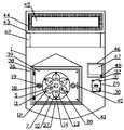
实现上述目的本发明的技术方案为,一种用于电动汽车的智能化太阳能充电桩,包括充电桩本体,所述充电桩本体位于两个停车位中间位置,一个充电桩本体可对此两个停车位两侧的合计六个停车位提供充电功能,所述充电桩本体上设有读卡机构、监控机构、防雨机构、提示机构、控制机构,所述充电桩本体一侧设有充电切换机构,The technical solution of the present invention to achieve the above object is that an intelligent solar charging pile for electric vehicles includes a charging pile body, the charging pile body is located in the middle of two parking spaces, and one charging pile body can be used for two A total of six parking spaces on both sides of the parking space provide charging functions. The charging pile body is provided with a card reading mechanism, a monitoring mechanism, a rainproof mechanism, a prompt mechanism, and a control mechanism, and a charging switch is provided on one side of the charging pile body. mechanism,
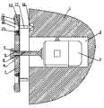
所述充电切换机构包括固定安装在充电桩本体一侧的太阳能发电装置,充电桩本体前侧表面上端开有方形凹槽,方形凹槽内安装有伺服电机,伺服电机旋转端末端安装有圆形挡板,伺服电机旋转端上端开有滑槽,伺服电机旋转端套装有转动板,转动板圆心位置开有圆孔,圆孔套装在伺服电机旋转端上,圆孔上端安装有滑块,滑块下端位于滑槽内,转动板上开有六个通孔,通孔以圆孔圆心为中心成圆周均匀分布,通孔一侧贴有标签,标签上设有标号,通孔内安装有塑料板,塑料板上设有三头插孔,塑料板上设有固定机构,方形凹槽上端设有三头充电口,三头充电口两侧开有限位孔,塑料板内侧表面两端安装有限位柱,限位柱一端伸入限位孔内,方形凹槽两侧安装有电动伸缩杆,两个电动伸缩杆伸缩端内侧分别安装有两个连接板,转动板位于两个连接板内侧。The charging switching mechanism includes a solar power generation device fixedly installed on one side of the charging pile body, a square groove is opened on the upper end of the front surface of the charging pile body, a servo motor is installed in the square groove, and a circular end is installed at the rotating end of the servo motor. The baffle plate, the upper end of the servo motor's rotating end is provided with a chute, the servo motor's rotating end is set with a rotating plate, the circular hole is opened at the center of the rotating plate, and the circular hole is set on the rotating end of the servo motor. The lower end of the block is located in the chute, and there are six through holes on the rotating plate. The through holes are evenly distributed in a circle with the center of the round hole as the center. A label is attached to one side of the through hole, and the label is provided with a label. The through hole is installed with plastic There are three sockets on the plastic board, a fixing mechanism on the plastic board, a three-point charging port on the upper end of the square groove, limit holes on both sides of the three-point charging port, and limit posts on both ends of the inner surface of the plastic board One end of the limit column extends into the limit hole, electric telescopic rods are installed on both sides of the square groove, two connecting plates are installed on the inner sides of the telescopic ends of the two electric telescopic rods, and the rotating plate is located inside the two connecting plates.
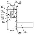
所述固定机构包括固定安装在三头插孔下端的固定块,固定块外侧表面开有弧形通槽,弧形通槽两侧开有螺纹孔,固定块前侧设有弧形压板,弧形压板与弧形通槽内侧表面安装有防滑垫,弧形压板两侧安装有固定板,固定板上开有连接孔,固定板一侧设有连接螺柱,连接螺柱一端穿过连接孔通过螺纹连接套装在螺纹孔内,连接螺柱外侧表面安装有连接环。The fixing mechanism includes a fixing block that is fixedly installed at the lower end of the three-head jack, the outer surface of the fixing block is provided with an arc-shaped through groove, the two sides of the arc-shaped through-groove are provided with threaded holes, and the front side of the fixing block is provided with an arc-shaped pressure plate. Anti-skid pads are installed on the inner surface of the shaped pressure plate and the arc-shaped through groove, and fixed plates are installed on both sides of the arc-shaped pressure plate. It is sleeved in the threaded hole through a threaded connection, and a connection ring is installed on the outer surface of the connection stud.
所述读卡机构包括固定安装在方形凹槽一侧的读卡器,读卡器前侧安装有卡槽,读卡器上的设有红色信号灯,红色信号灯一侧设有绿色信号灯。The card reading mechanism includes a card reader fixedly installed on one side of the square groove, a card slot is installed on the front side of the card reader, a red signal light is provided on the card reader, and one side of the red signal light is provided with a green signal light.
所述监控机构包括固定安装在充电桩本体一侧的监控柱,监控柱上端两侧安装有防雨挡盖,防雨挡盖下表面安装有无线监控摄像头。The monitoring mechanism includes a monitoring column fixedly installed on one side of the charging pile body, a rainproof cover is installed on both sides of the upper end of the monitoring column, and a wireless monitoring camera is installed on the lower surface of the rainproof cover.
所述防雨机构包括固定安装在充电桩本体前侧表面上端的透明防护外壳,透明防护外壳将转动板和电动伸缩杆包裹在内,透明防护外壳下端开有进线孔,透明防护外壳前侧开有方形开口,方形开口处安装有透明防护门,透明防护门一侧安装有拉动把手,透明防护门内侧表面上下端安装有连接弹簧,连接弹簧一端与透明防护外壳内侧表面固定连接。The rainproof mechanism includes a transparent protective casing fixedly installed on the upper end of the front surface of the charging pile body, the transparent protective casing wraps the rotating plate and the electric telescopic rod, the lower end of the transparent protective casing is provided with a wire inlet hole, and the front side of the transparent protective casing is opened. A square opening is opened, a transparent protective door is installed at the square opening, a pull handle is installed on one side of the transparent protective door, a connecting spring is installed on the upper and lower ends of the inner surface of the transparent protective door, and one end of the connecting spring is fixedly connected with the inner surface of the transparent protective shell.
所述提示机构包括固定安装在充电桩本体上表面两侧的连接柱,连接柱上表面安装有盛放板,盛放板两侧表面安装有LED显示屏,LED显示屏上显示有充电剩余时间信息。The prompting mechanism includes connection posts fixedly installed on both sides of the upper surface of the charging pile body, a storage board is installed on the upper surface of the connection post, LED display screens are installed on both sides of the storage board, and the remaining charging time is displayed on the LED display screen. information.
所述控制机构包括固定安装在读卡器上端的控制器,控制器前侧设有电容显示屏,电容显示屏下端安装有启动按键。The control mechanism includes a controller fixedly installed on the upper end of the card reader, a capacitive display screen is arranged on the front side of the controller, and a start button is installed on the lower end of the capacitive display screen.
所述充电切换机构位于充电桩本体前侧表面上端,读卡机构位于充电切换机构内的方形凹槽一侧,监控机构位于充电桩本体一侧地面上,防雨机构位于充电切换机构内的方形凹槽外侧,提示机构位于充电桩本体上端,控制机构位于读卡机构内的读卡器上方。The charging switching mechanism is located at the upper end of the front surface of the charging pile body, the card reading mechanism is located on the side of the square groove in the charging switching mechanism, the monitoring mechanism is located on the ground on one side of the charging pile body, and the rainproof mechanism is located on the square inside the charging switching mechanism. Outside the groove, the prompting mechanism is located at the upper end of the charging pile body, and the control mechanism is located above the card reader in the card reading mechanism.
利用本发明的技术方案制作的用于电动汽车的太阳能充电桩,由车主将充电器插入三头插孔中,并将充电器另一端与电动汽车连接,通过伺服电机的带动和电动伸缩杆的伸缩,可自动将充电器进行插拔和更换,无需人工进行排队,将充点卡放入卡槽内,并在控制器上设定充电的时间,达到一定时间后,可将充电桩自动拔出,防止浪费公共资源,通过无线摄像头可对此位置进行监控,防止物品丢失,在LED显示屏上显示的充电剩余时间,可便于车主在远处找到适合的停车位进行充电,防止停好车辆在需要充电时,发现太阳能充电桩无法充电,需要重新寻找车位,此装置可大量减少太阳能充电桩的建造数量,并保证有足够电动汽车可以充电,降低了建造成本,并且合理的利用公共资源,防止公共资源被浪费。The solar charging pile for electric vehicles made by using the technical solution of the present invention, the owner inserts the charger into the three-head jack, and connects the other end of the charger with the electric vehicle, driven by the servo motor and the electric telescopic rod. Telescopic, can automatically plug and replace the charger, without manual queuing, put the charging point card into the card slot, and set the charging time on the controller, after a certain time, the charging pile can be automatically pulled out To prevent wasting public resources, the location can be monitored through wireless cameras to prevent items from being lost, and the remaining charging time displayed on the LED display can help car owners find a suitable parking space for charging at a distance, preventing the vehicle from being parked. When charging is required, it is found that the solar charging pile cannot be charged, and it is necessary to find a parking space again. This device can greatly reduce the construction number of solar charging piles, and ensure that enough electric vehicles can be charged, which reduces the construction cost and makes reasonable use of public resources. Prevent public resources from being wasted.
附图说明Description of drawings
图1是本发明所述用于电动汽车的太阳能充电桩的结构示意图;1 is a schematic structural diagram of a solar charging pile for electric vehicles according to the present invention;
图2是本发明所述用于电动汽车的太阳能充电桩的局部放大图;2 is a partial enlarged view of the solar charging pile for electric vehicles according to the present invention;
图3是本发明所述连接板和转动板的位置关系示意图;3 is a schematic diagram of the positional relationship between the connecting plate and the rotating plate according to the present invention;
图4是本发明所述充电切换机构的局部示意图;4 is a partial schematic diagram of the charging switching mechanism of the present invention;
图5是本发明所述限位柱和三头充电口的位置关系示意图;5 is a schematic diagram of the positional relationship between the limit post and the three-head charging port according to the present invention;
图6是本发明所述固定机构的局部放大图;6 is a partial enlarged view of the fixing mechanism of the present invention;
图7是本发明所述固定机构的局部示意图;7 is a partial schematic view of the fixing mechanism of the present invention;
图中,1、充电桩本体;2、太阳能发电装置;3、方形凹槽;4、伺服电机;5、圆形挡板;6、滑槽;7、转动板;8、圆孔;9、滑块;10、通孔;11、标签;12、标号;13、塑料板;14、三头插孔;15、三头充电口;16、限位孔;17、限位柱;18、电动伸缩杆;19、连接板;20、固定块;21、弧形通槽;22、螺纹孔;23、弧形压板;24、防滑垫;25、固定板;26、连接孔;27、连接螺柱;28、连接环;29、读卡器;30、卡槽;31、红色信号灯;32、绿色信号灯;33、监控柱;34、防雨挡盖;35、无线监控摄像头;36、透明防护外壳;37、进线孔;38、方形开口;39、透明防护门;40、拉动把手;41、连接弹簧;42、连接柱;43、盛放板;44、LED显示屏;45、充电剩余时间信息;46、控制器;47、电容显示屏;48、启动按键。In the figure, 1. Charging pile body; 2. Solar power generation device; 3. Square groove; 4. Servo motor; 5. Circular baffle; 6. Chute; 7. Rotating plate; 8. Round hole; 9. Slider; 10, through hole; 11, label; 12, label; 13, plastic plate; 14, three-head jack; 15, three-head charging port; 16, limit hole; 17, limit post; 18, electric Telescopic rod; 19, connecting plate; 20, fixing block; 21, arc through slot; 22, threaded hole; 23, arc pressure plate; 24, anti-skid pad; 25, fixing plate; 26, connecting hole; 27, connecting screw Column; 28, connecting ring; 29, card reader; 30, card slot; 31, red signal light; 32, green signal light; 33, monitoring column; 34, rainproof cover; 35, wireless surveillance camera; 36, transparent protection Shell; 37, wire inlet; 38, square opening; 39, transparent protective door; 40, pull handle; 41, connection spring; 42, connection post; 43, storage board; 44, LED display screen; 45, remaining charging Time information; 46, controller; 47, capacitive display screen; 48, start button.
具体实施方式Detailed ways
下面结合附图对本发明进行具体描述,如图1-7所示。The present invention will be described in detail below with reference to the accompanying drawings, as shown in FIGS. 1-7 .
在本实施方案中,通过控制器46进行控制,控制器46的型号为TPC4-4TDC,控制器46的电源接入端与太阳能发电装置2的电源输出端电性连接从而通电,太阳能发电装置2的电源输出端分别与充电桩本体1、伺服电机4、电动伸缩杆18、读卡器29、无线监控摄像头35、LED显示屏44电性连接并进行供电,控制器46的控制信号输出端通过与伺服电机4、电动伸缩杆18、读卡器29、无线监控摄像头35、LED显示屏44电性连接并通过继电器控制其运行。In this embodiment, the
本申请的创造点在于充电切换机构的结构设计,在本装置中结合附图2和附图4,充电切换机构包括固定安装在充电桩本体1一侧的太阳能发电装置2,充电桩本体1前侧表面上端开有方形凹槽3,方形凹槽3内安装有伺服电机4,伺服电机4旋转端末端安装有圆形挡板5,伺服电机4旋转端上端开有滑槽6,伺服电机4旋转端套装有转动板7,转动板7圆心位置开有圆孔8,圆孔8套装在伺服电机4旋转端上,圆孔8上端安装有滑块9,滑块9下端位于滑槽6内,转动板7上开有六个通孔10,通孔10以圆孔8圆心为中心成圆周均匀分布,通孔10一侧贴有标签11,标签11上设有标号12,通孔10内安装有塑料板13,塑料板13上设有三头插孔14,塑料板13上设有固定机构,方形凹槽3上端设有三头充电口15,三头充电口15两侧开有限位孔16,塑料板13内侧表面两端安装有限位柱17,限位柱17一端伸入限位孔16内,方形凹槽3两侧安装有电动伸缩杆18,两个电动伸缩杆18伸缩端内侧分别安装有两个连接板19,转动板7位于两个连接板19内侧,其主要解决的问题为:将充电器插头插入三头插孔14内,通过电动伸缩杆18的伸缩带动转动板7沿着滑槽6移动,将充电器插入三头充电口15内进行充电,通过电动伸缩杆18的伸缩可将充电器进行插拔,通过伺服电机4的转动,可在充电结束后,自动切换充电器进行充电,无需车主等待排队,节省时间,The invention of the present application lies in the structural design of the charging switching mechanism. In this device, referring to Figures 2 and 4 , the charging switching mechanism includes a solar power generation device 2 that is fixedly installed on one side of the charging
本申请内还设有读卡机构、监控机构、防雨机构、提示机构、控制机构,由车主将充电卡放入读卡机构内卡槽30内,亮起红色信号灯31,并在控制机构内的电容显示屏47上进行操作,设定充电时间,当完成后,亮起绿色信号灯32,将充电卡取出,通过监控内的无线监控摄像头35可对附近进行监控,防止物品丢失,将充电器由防雨机构内的进线孔37放入透明防护外壳36内并进行固定,透明防护门39可在连接弹簧41的作用下,自动关闭,保证防雨效果,提示机构内的LED显示屏44可显示此装置的充电剩余时间信息45,便于车主选择是否在此处停车,便于使用,其具体工作步骤如下:The application also has a card reader mechanism, a monitoring mechanism, a rainproof mechanism, a prompt mechanism, and a control mechanism. The vehicle owner puts the charging card into the card slot 30 of the card reader mechanism, lights up the red signal light 31, and displays the charging card in the control mechanism. Operate on the capacitive display screen 47 of the device to set the charging time. When the charging is completed, the green signal light 32 is turned on, and the charging card is taken out. The wire inlet hole 37 in the rainproof mechanism is put into the transparent
第一步、连接充电器:车主在将车辆开进停车场时,在远处观察LED显示屏44上显示的充电剩余时间信息45,从而根据自己的时间,选择对应的停车位进行停车,由车主取出充电器,将充电器充电端与电动汽车连接,将另一端由进线孔37放入透明防护外壳36内,拉开透明防护门39,扭动连接螺柱27,通过螺纹连接将连接螺柱27取出一端,使得弧形压板23与固定块20之间有足够的距离,将充电器的插头端由弧形压板23下端穿过弧形通槽21并插入三头插孔14内,并拧紧连接螺柱27,通过防滑垫24将充电器插头固定,车主拿出挂锁将两个连接环28锁住,防止被别人将充电器更换位置,松开透明防护门39,透明防护门39在连接弹簧41的弹力作用下,自动关闭,通过无线监控摄像头35可防止物品丢失,在此过程中,车主便于选择适合的停车位,节省停车时间,并且通过摄像头可防止物品丢失,透明防护门39可自动关闭,便于防雨,The first step, connect the charger: when the car owner drives the vehicle into the parking lot, he observes the remaining
第二步、充电设定:由车主将充电卡放入卡槽30内,当读卡器29感应到后,亮起红色信号灯32,由车主按下启动按键48,电容显示屏47亮起,由车主根据电动汽车剩余的电量选择大概的充电时间,选择完毕后,亮起绿色信号灯32,设置完成,取出充电卡,电容显示屏47自动关闭,并由控制器46控制在LED显示屏44上显示的充电剩余时间信息45增加相应的时间,在此过程中,设定好时间后,即可由此装置自动运行,无需车主排队等候,使用方便,The second step, charging setting: the car owner puts the charging card into the card slot 30, when the
第三步、自动更换:当正在充电的充电器时间未到达却充满电时,或时间到达却还差一点充满时,均相应的延长一段时间,保证其电量充足,并根据充电的电量对相应的充电卡进行扣费,当需要更换充电器时,启动电动伸缩杆18伸长,通过转动板7内侧的连接板19将转动板7向外侧推动,通过滑块9和滑槽6和保证其移动方向,当充电器的插头从三头充电口15上掉落拔出时,限位柱17从限位孔16内取出,关闭电动伸缩杆18,启动伺服电机4转动,伺服电机4自身具有检测转动角度的功能,将下一个位置的充电器插头移动到三头充电口15前侧,启动电动伸缩杆18缩短,通过转动板7外侧的连接板19将转动板7向内侧推动,限位柱17进入限位孔16内,并将充电器的插头插入三头充电口15内进行充电,在此过程中,此装置可自动更换充电器,并对不同的电动汽车进行充电,减少了建造太阳能充电桩的数量,降低了建造成本,通过自动切换充电器,可保证对足够数量的电动汽车进行充电,使用方便。The third step, automatic replacement: when the charging charger is fully charged before the time arrives, or when the time arrives but it is almost fully charged, it will be extended for a period of time accordingly to ensure that its power is sufficient, and the corresponding charge will be adjusted according to the charging power. When the charger needs to be replaced, start the electric
上述技术方案仅体现了本发明技术方案的优选技术方案,本技术领域的技术人员对其中某些部分所可能做出的一些变动均体现了本发明的原理,属于本发明的保护范围之内。The above technical solutions only represent the preferred technical solutions of the technical solutions of the present invention, and some changes that those skilled in the art may make to some parts of them all reflect the principles of the present invention and fall within the protection scope of the present invention.
Claims (8)
Translated fromChinesePriority Applications (1)
| Application Number | Priority Date | Filing Date | Title |
|---|---|---|---|
| CN202010152280.3ACN111186328B (en) | 2020-03-06 | 2020-03-06 | Intelligent solar charging pile for electric automobile |
Applications Claiming Priority (1)
| Application Number | Priority Date | Filing Date | Title |
|---|---|---|---|
| CN202010152280.3ACN111186328B (en) | 2020-03-06 | 2020-03-06 | Intelligent solar charging pile for electric automobile |
Publications (2)
| Publication Number | Publication Date |
|---|---|
| CN111186328A CN111186328A (en) | 2020-05-22 |
| CN111186328Btrue CN111186328B (en) | 2020-09-08 |
Family
ID=70704801
Family Applications (1)
| Application Number | Title | Priority Date | Filing Date |
|---|---|---|---|
| CN202010152280.3AExpired - Fee RelatedCN111186328B (en) | 2020-03-06 | 2020-03-06 | Intelligent solar charging pile for electric automobile |
Country Status (1)
| Country | Link |
|---|---|
| CN (1) | CN111186328B (en) |
Families Citing this family (1)
| Publication number | Priority date | Publication date | Assignee | Title |
|---|---|---|---|---|
| CN112018846A (en)* | 2020-08-27 | 2020-12-01 | 深圳瑞福来智能科技股份有限公司 | Car fills with self-checking function and has automatic structure that drops |
Family Cites Families (5)
| Publication number | Priority date | Publication date | Assignee | Title |
|---|---|---|---|---|
| JP2011135660A (en)* | 2009-12-23 | 2011-07-07 | Aichi Electric Co Ltd | Charging apparatus |
| CN206446456U (en)* | 2017-01-26 | 2017-08-29 | 营口福泰科技有限责任公司 | The multitap charging system of quickly-chargeable |
| CN208993497U (en)* | 2018-08-13 | 2019-06-18 | 青岛海汇德电气有限公司 | A kind of charging system |
| CN109249831A (en)* | 2018-10-13 | 2019-01-22 | 樊六九 | A kind of charging electric motor vehicles stake based on solar power generation |
| CN109986987A (en)* | 2019-05-07 | 2019-07-09 | 吉林大学青岛汽车研究院 | A shared charging system and charging method for electric vehicles based on solar energy and electric energy |
- 2020
- 2020-03-06CNCN202010152280.3Apatent/CN111186328B/ennot_activeExpired - Fee Related
Also Published As
| Publication number | Publication date |
|---|---|
| CN111186328A (en) | 2020-05-22 |
Similar Documents
| Publication | Publication Date | Title |
|---|---|---|
| CN201623233U (en) | Charging device and charging wire-containing box of electric vehicle | |
| CN221417981U (en) | Charging pile capable of automatically opening and closing charging gun head storage box | |
| CN108961827A (en) | A kind of energy-saving parking space management system of triggering wake-up formula and parking stall management method | |
| CN111186328B (en) | Intelligent solar charging pile for electric automobile | |
| CN206327180U (en) | A kind of charging pile for electric automobile Reserved Parking | |
| CN206173844U (en) | Parking stall lock with function of charging | |
| CN109130923B (en) | Charging pile with parking space control function | |
| CN109519021B (en) | An outdoor electric vehicle parking space lock device | |
| CN110084945A (en) | A kind of non-motor vehicle intelligent parking system based on iPark smart lock | |
| CN219339220U (en) | Roadside charging system based on transfer robot | |
| CN201180386Y (en) | Intelligent remote control parking space brake | |
| CN117533177A (en) | Dual-redundancy self-protection mutual-backup integrated energy-saving charging pile | |
| CN210288196U (en) | Intelligent parking spot lock | |
| CN110789381A (en) | New energy charging pile | |
| CN218858186U (en) | Card-swiping type intelligent platform charging pile | |
| CN206870947U (en) | Automobile triangular board mobile device and system | |
| CN206865170U (en) | A kind of compound charging device of electric automobile | |
| CN209443851U (en) | Lead screw swing rod pull-type bicycle parking garage | |
| CN206591889U (en) | A kind of public parking space management system | |
| CN213399682U (en) | Smart city roadside parking charge supervision device | |
| CN215042195U (en) | Intelligent charging stake with face discernment | |
| CN214689086U (en) | New energy automobile charges with filling electric pile with rain-proof function | |
| CN212529350U (en) | New energy automobile is with novel electric pile that fills | |
| CN212835130U (en) | Intelligent parking ground lock | |
| CN208379501U (en) | One kind is intelligently locked |
Legal Events
| Date | Code | Title | Description |
|---|---|---|---|
| PB01 | Publication | ||
| PB01 | Publication | ||
| SE01 | Entry into force of request for substantive examination | ||
| SE01 | Entry into force of request for substantive examination | ||
| TA01 | Transfer of patent application right | Effective date of registration:20200723 Address after:Room 1805, building 2, Fuchen Business Plaza, Xinbei District, Changzhou City, Jiangsu Province Applicant after:Changzhou MAIYUE Semiconductor Co.,Ltd. Address before:537200 GuiGui road Xishan Yufu 3-1-201, Guiping City, Guigang City, Guangxi Zhuang Autonomous Region Applicant before:Luo Guihai | |
| TA01 | Transfer of patent application right | ||
| TA01 | Transfer of patent application right | ||
| TA01 | Transfer of patent application right | Effective date of registration:20200812 Address after:Room 11, 17 / F, waita commercial building, 1a-1l Tong Choi Street, Kowloon, Hong Kong, China Applicant after:Xiangxingsheng Porcelain Art Co.,Ltd. Address before:Room 1805, building 2, Fuchen Business Plaza, Xinbei District, Changzhou City, Jiangsu Province Applicant before:Changzhou MAIYUE Semiconductor Co.,Ltd. | |
| GR01 | Patent grant | ||
| GR01 | Patent grant | ||
| TR01 | Transfer of patent right | Effective date of registration:20201123 Address after:Room 368, administrative service center, cluster district, Taizhou, Zhejiang Province Patentee after:Hengzhiyu Trading Co.,Ltd. Address before:Room 11, 17 / F, waita commercial building, 1a-1l Tong Choi Street, Kowloon, Hong Kong, China Patentee before:Xiangxingsheng Porcelain Art Co.,Ltd. | |
| TR01 | Transfer of patent right | ||
| CF01 | Termination of patent right due to non-payment of annual fee | Granted publication date:20200908 | |
| CF01 | Termination of patent right due to non-payment of annual fee |