Movatterモバイル変換


[0]ホーム

URL:


CN111182848B - Removable dental appliance including a positioning member - Google Patents

Removable dental appliance including a positioning member
Download PDF

Info

Publication number
CN111182848B
CN111182848BCN201880064888.1ACN201880064888ACN111182848BCN 111182848 BCN111182848 BCN 111182848BCN 201880064888 ACN201880064888 ACN 201880064888ACN 111182848 BCN111182848 BCN 111182848B
Authority
CN
China
Prior art keywords
appliance
removable dental
patient
attachment
spring member
Prior art date
Legal status (The legal status is an assumption and is not a legal conclusion. Google has not performed a legal analysis and makes no representation as to the accuracy of the status listed.)
Active
Application number
CN201880064888.1A
Other languages
Chinese (zh)
Other versions
CN111182848A (en
Inventor
拉尔夫·M·佩尔
小戴维·K·齐纳德
詹姆士·D·哈森
理查德·E·拉比
迈克尔·K·多姆罗伊塞
Current Assignee (The listed assignees may be inaccurate. Google has not performed a legal analysis and makes no representation or warranty as to the accuracy of the list.)
Shuwanuo Intellectual Property Co
Original Assignee
3M Innovative Properties Co
Priority date (The priority date is an assumption and is not a legal conclusion. Google has not performed a legal analysis and makes no representation as to the accuracy of the date listed.)
Filing date
Publication date
Application filed by 3M Innovative Properties CofiledCritical3M Innovative Properties Co
Publication of CN111182848ApublicationCriticalpatent/CN111182848A/en
Application grantedgrantedCritical
Publication of CN111182848BpublicationCriticalpatent/CN111182848B/en
Activelegal-statusCriticalCurrent
Anticipated expirationlegal-statusCritical

Links

Images

Classifications

Landscapes

Abstract

Translated fromChinese

本发明提供了一种可移除牙科器具,所述可移除牙科器具可包括被构造成至少部分地围绕多颗牙齿的器具主体。所述器具主体可以包括单一材料,所述单一材料限定被成形为接纳所述患者的至少一颗牙齿的壳体;与所述壳体一体形成的弹簧构件;以及与所述壳体一体形成的定位构件。所述弹簧构件可以被构造成接纳附连到所述至少一颗牙齿的附接件。所述弹簧构件可以被构造成当所述可移除牙科器具被所述患者佩戴时向所述附接件施加弹簧力,以引起所述至少一颗牙齿朝向期望位置的移动。所述定位构件可以被构造成响应于定位力被施加到所述定位构件而促进所述弹簧构件与所述附接件的接合。

Figure 201880064888

The present invention provides a removable dental appliance that can include an appliance body configured to at least partially surround a plurality of teeth. The appliance body may comprise a single material defining a housing shaped to receive at least one tooth of the patient; a spring member formed integrally with the housing; and a spring member formed integrally with the housing Position the widget. The spring member may be configured to receive an attachment attached to the at least one tooth. The spring member may be configured to apply a spring force to the attachment to cause movement of the at least one tooth toward a desired position when the removable dental appliance is worn by the patient. The positioning member may be configured to facilitate engagement of the spring member with the attachment in response to a positioning force being applied to the positioning member.

Figure 201880064888

Description

Translated fromChinese
包括定位构件的可移除牙科器具Removable dental appliance including positioning member

技术领域technical field

本公开涉及基于聚合物的可移除牙科器具诸如矫治器托盘。The present disclosure relates to polymer-based removable dental appliances such as appliance trays.

背景技术Background technique

正畸领域涉及重新定位患者的牙齿以改善功能和美学外观。正畸装置和治疗方法通常涉及施加力以将牙齿移动到适当的咬合构造或咬合。作为一个示例,正畸治疗可涉及使用被称为托槽的开槽器具,该开槽器具固定到患者的前牙、犬齿和双尖齿。弓丝通常安置在每个托槽的狭槽中,并且用作轨道来引导牙齿移动到期望的取向。弓丝的端部通常接纳在固定到患者的臼齿的被称作颊面管的器具中。此类牙科器具保持在患者口中,并且由正畸医生定期调节以检查该过程并保持对牙齿的适当压力,直到实现正确对齐。The field of orthodontics involves repositioning a patient's teeth to improve function and aesthetic appearance. Orthodontic devices and treatments generally involve applying force to move the teeth into the proper occlusal configuration or bite. As one example, orthodontic treatment may involve the use of slotted appliances called brackets that are secured to a patient's anterior, canine, and bicuspid teeth. An arch wire is typically placed in the slot of each bracket and serves as a track to guide the movement of the teeth to the desired orientation. The ends of the archwires are typically received in appliances called buccal tubes that are secured to the patient's molars. Such dental appliances remain in the patient's mouth and are regularly adjusted by the orthodontist to check the process and maintain proper pressure on the teeth until proper alignment is achieved.

正畸治疗还可涉及使用基于聚合物的牙齿矫治器托盘诸如透明托盘矫治器(CTA)。例如,使用CTA的正畸治疗可包括形成具有联接一颗或多颗牙齿的壳体的托盘。每个壳体可从牙齿的初始位置例如错位咬合位置变形。变形位置可以在初始位置和由正畸治疗产生的期望位置之间。CTA的相应壳体的变形位置可以向相应的牙齿施加朝向期望位置的力。Orthodontic treatment may also involve the use of polymer-based appliance trays such as clear tray appliances (CTA). For example, orthodontic treatment using CTA may include forming a tray with a housing that joins one or more teeth. Each shell is deformable from an initial position of the teeth, eg, a misaligned position. The deformed position may be between the initial position and the desired position resulting from the orthodontic treatment. The deformed positions of the respective housings of the CTA may apply a force towards the desired position to the respective teeth.

发明内容SUMMARY OF THE INVENTION

本公开描述了可移除牙科器具(诸如矫治器托盘)以及制造所述可移除牙科器具的技术,所述可移除牙科器具包括器具主体,该器具主体包括形成在其中的定位构件,以促进该器具的弹簧构件与附连到牙齿的附接件的接合。The present disclosure describes removable dental appliances, such as appliance trays, and techniques for manufacturing the same, including an appliance body including a positioning member formed therein to Engagement of the spring member of the appliance with the attachment attached to the tooth is facilitated.

在一些示例中,本公开描述了一种可移除牙科器具,其包括器具主体,该器具主体被构造成至少部分地围绕患者的牙弓的多颗牙齿。该器具主体可以包括单一材料,该单一材料限定被成形为接纳患者的至少一颗牙齿的壳体;与该壳体一体形成的弹簧构件;以及与该壳体一体形成的定位构件。该弹簧构件可以被构造成接纳附连到至少一颗牙齿的附接件。该弹簧构件可以被构造成当可移除牙科器具被患者佩戴时向附接件施加弹簧力,以引起至少一颗牙齿朝向期望位置的移动。该定位构件可以被构造成响应于定位力被施加到定位构件而促进弹簧构件与附接件的接合。In some examples, the present disclosure describes a removable dental appliance that includes an appliance body configured to at least partially surround a plurality of teeth of a patient's dental arch. The appliance body may comprise a single material defining a housing shaped to receive at least one tooth of the patient; a spring member formed integrally with the housing; and a positioning member formed integrally with the housing. The spring member may be configured to receive an attachment attached to the at least one tooth. The spring member may be configured to apply a spring force to the attachment to cause movement of the at least one tooth towards a desired position when the removable dental appliance is worn by the patient. The positioning member may be configured to facilitate engagement of the spring member with the attachment in response to a positioning force being applied to the positioning member.

在一些示例中,本公开描述了一种系统,该系统包括一组有序的可移除牙科器具,该组有序的可移除牙科器具被构造用于重新定位患者的一颗或多颗牙齿。该组可移除牙科器具中的至少一个可移除牙科器具包括器具主体,该器具主体被构造成至少部分地围绕患者的牙弓的多颗牙齿。该器具主体可以包括单一材料,该单一材料限定被成形为接纳患者的至少一颗牙齿的壳体;与该壳体一体形成的弹簧构件;以及与该壳体一体形成的定位构件。该弹簧构件可以被构造成接纳附连到至少一颗牙齿的附接件。该弹簧构件可以被构造成当可移除牙科器具被患者佩戴时向附接件施加弹簧力,以引起至少一颗牙齿朝向期望位置的移动。该定位构件可以被构造成响应于定位力被施加到定位构件而促进弹簧构件与附接件的接合。In some examples, the present disclosure describes a system that includes an ordered set of removable dental appliances configured to reposition one or more of a patient teeth. At least one removable dental appliance of the set of removable dental appliances includes an appliance body configured to at least partially surround a plurality of teeth of a patient's dental arch. The appliance body may comprise a single material defining a housing shaped to receive at least one tooth of the patient; a spring member formed integrally with the housing; and a positioning member formed integrally with the housing. The spring member may be configured to receive an attachment attached to the at least one tooth. The spring member may be configured to apply a spring force to the attachment to cause movement of the at least one tooth towards a desired position when the removable dental appliance is worn by the patient. The positioning member may be configured to facilitate engagement of the spring member with the attachment in response to a positioning force being applied to the positioning member.

在一些示例中,本公开描述了一种方法,该方法包括形成患者的包括期望牙齿位置的牙科解剖结构的模型;以及基于该模型形成可移除牙科器具。该可移除牙科器具可包括器具主体,该器具主体被构造成至少部分地围绕患者的牙弓的多颗牙齿。该器具主体可以包括单一材料,该单一材料限定被成形为接纳患者的至少一颗牙齿的壳体;与该壳体一体形成的弹簧构件;以及与该壳体一体形成的定位构件。该弹簧构件可以被构造成接纳附连到至少一颗牙齿的附接件。该弹簧构件可以被构造成当可移除牙科器具被患者佩戴时向附接件施加弹簧力,以引起至少一颗牙齿朝向期望位置的移动。该定位构件可以被构造成响应于定位力被施加到定位构件而促进弹簧构件与附接件的接合。In some examples, the present disclosure describes a method comprising forming a model of a patient's dental anatomy including desired tooth positions; and forming a removable dental appliance based on the model. The removable dental appliance may include an appliance body configured to at least partially surround a plurality of teeth of a patient's dental arch. The appliance body may comprise a single material defining a housing shaped to receive at least one tooth of the patient; a spring member formed integrally with the housing; and a positioning member formed integrally with the housing. The spring member may be configured to receive an attachment attached to the at least one tooth. The spring member may be configured to apply a spring force to the attachment to cause movement of the at least one tooth towards a desired position when the removable dental appliance is worn by the patient. The positioning member may be configured to facilitate engagement of the spring member with the attachment in response to a positioning force being applied to the positioning member.

在一些示例中,本公开描述了一种方法,该方法包括通过计算装置接收患者的三维(3D)牙科解剖结构的数字表示,该牙科解剖结构提供患者的一颗或多颗牙齿的初始位置。该方法还可包括通过计算装置确定用于患者的可移除牙科器具的尺寸和形状。该可移除牙科器具可包括器具主体,该器具主体被构造成至少部分地围绕患者的牙弓的多颗牙齿。该器具主体可以包括单一材料,该单一材料限定被成形为接纳患者的至少一颗牙齿的壳体;与该壳体一体形成的弹簧构件;以及与该壳体一体形成的定位构件。该弹簧构件可以被构造成接纳附连到至少一颗牙齿的附接件。该弹簧构件可以被构造成当可移除牙科器具被患者佩戴时向附接件施加弹簧力,以引起至少一颗牙齿朝向期望位置的移动。该定位构件可以被构造成响应于定位力被施加到定位构件而促进弹簧构件与附接件的接合。该可移除牙科器具的尺寸和形状可包括:壳体的位置、尺寸和形状;附接件的位置、尺寸和形状;弹簧构件的位置、尺寸和形状;以及定位构件的位置、尺寸和形状。该方法还可包括通过计算装置将可移除牙科器具的表示传输到计算机辅助的制造系统。In some examples, the present disclosure describes a method that includes receiving, by a computing device, a digital representation of a three-dimensional (3D) dental anatomy of a patient, the dental anatomy providing an initial position of one or more teeth of the patient. The method may also include determining, by the computing device, the size and shape of the removable dental appliance for the patient. The removable dental appliance may include an appliance body configured to at least partially surround a plurality of teeth of a patient's dental arch. The appliance body may comprise a single material defining a housing shaped to receive at least one tooth of the patient; a spring member formed integrally with the housing; and a positioning member formed integrally with the housing. The spring member may be configured to receive an attachment attached to the at least one tooth. The spring member may be configured to apply a spring force to the attachment to cause movement of the at least one tooth towards a desired position when the removable dental appliance is worn by the patient. The positioning member may be configured to facilitate engagement of the spring member with the attachment in response to a positioning force being applied to the positioning member. The size and shape of the removable dental appliance may include: the position, size and shape of the housing; the position, size and shape of the attachment; the position, size and shape of the spring member; and the position, size and shape of the positioning member . The method may also include transmitting, by the computing device, the representation of the removable dental appliance to the computer-aided manufacturing system.

在一些示例中,本公开描述了存储计算机系统可执行指令的非暂态计算机可读存储介质,该计算机系统可执行指令在被执行时可将处理器配置为通过计算装置接收患者的三维(3D)牙科解剖结构的数字表示,该牙科解剖结构提供患者的一颗或多颗牙齿的初始位置。非暂态计算机可读存储介质还存储计算机系统还可执行指令,该计算机系统可执行指令在被执行时可将处理器配置为通过计算装置确定患者的可移除牙科器具的尺寸和形状。该可移除牙科器具可包括器具主体,该器具主体被构造成至少部分地围绕患者的牙弓的多颗牙齿。该器具主体可以包括单一材料,该单一材料限定被成形为接纳患者的至少一颗牙齿的壳体;与该壳体一体形成的弹簧构件;以及与该壳体一体形成的定位构件。该弹簧构件可以被构造成接纳附连到至少一颗牙齿的附接件。该弹簧构件可以被构造成当可移除牙科器具被患者佩戴时向附接件施加弹簧力,以引起至少一颗牙齿朝向期望位置的移动。该定位构件可以被构造成响应于定位力被施加到定位构件而促进弹簧构件与附接件的接合。该可移除牙科器具的尺寸和形状可包括:壳体的位置、尺寸和形状;附接件的位置、尺寸和形状;弹簧构件的位置、尺寸和形状;以及定位构件的位置、尺寸和形状。非暂态计算机可读存储介质还可存储计算机系统可执行指令,该计算机系统可执行指令在被执行时可将处理器配置为通过计算装置将可移除牙科器具的表示传输到计算机辅助的制造系统。In some examples, the present disclosure describes a non-transitory computer-readable storage medium storing computer system-executable instructions that, when executed, configure a processor to receive, via a computing device, a three-dimensional (3D) image of a patient. ) a numerical representation of a dental anatomy that provides the initial position of one or more teeth of a patient. The non-transitory computer readable storage medium also stores computer system executable instructions that, when executed, configure the processor to determine, via the computing device, the size and shape of the patient's removable dental appliance. The removable dental appliance may include an appliance body configured to at least partially surround a plurality of teeth of a patient's dental arch. The appliance body may comprise a single material defining a housing shaped to receive at least one tooth of the patient; a spring member formed integrally with the housing; and a positioning member formed integrally with the housing. The spring member may be configured to receive an attachment attached to the at least one tooth. The spring member may be configured to apply a spring force to the attachment to cause movement of the at least one tooth towards a desired position when the removable dental appliance is worn by the patient. The positioning member may be configured to facilitate engagement of the spring member with the attachment in response to a positioning force being applied to the positioning member. The size and shape of the removable dental appliance may include: the position, size and shape of the housing; the position, size and shape of the attachment; the position, size and shape of the spring member; and the position, size and shape of the positioning member . The non-transitory computer-readable storage medium may also store computer system-executable instructions that, when executed, configure the processor to transmit a representation of the removable dental appliance to the computer-aided manufacturing via the computing device system.

本公开的一个或多个实施例的细节在附图和以下描述中进行阐述。从说明书和附图、以及从权利要求书中,本公开的其它特征、目标和优点将显而易见。The details of one or more embodiments of the disclosure are set forth in the accompanying drawings and the description below. Other features, objects, and advantages of the present disclosure will be apparent from the description and drawings, and from the claims.

附图说明Description of drawings

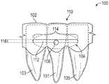
图1A、图1B、图1C和图1D示出示例性可移除牙科器具的颊侧视图和横剖视图,该可移除牙科器具包括弹簧构件以接合患者牙齿上的附接件。1A, IB, 1C, and ID show buccal and cross-sectional views of an exemplary removable dental appliance that includes a spring member to engage an attachment on a patient's teeth.

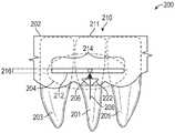
图2A、图2B和图2C示出示例性可移除牙科器具的颊侧视图,该可移除牙科器具包括定位构件,用于促进弹簧构件与患者牙齿上的附接件的接合。2A, 2B, and 2C illustrate buccal views of an exemplary removable dental appliance that includes a positioning member for facilitating engagement of a spring member with an attachment on a patient's teeth.

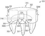
图3A、图3B和图3C示出示例性可移除牙科器具的颊侧视图,该可移除牙科器具包括定位构件和挠曲区域,用于促进弹簧构件与患者牙齿上的附接件的接合。Figures 3A, 3B and 3C show buccal views of an exemplary removable dental appliance including a positioning member and a flexure region for facilitating the engagement of the spring member with the attachment on the patient's teeth engage.

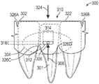
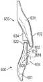
图4A、图4B和图4C示出示例性可移除牙科器具的颊侧视图,该可移除牙科器具包括偏移定位构件,用于促进弹簧构件与患者牙齿上的附接件的接合。4A, 4B, and 4C illustrate buccal views of an exemplary removable dental appliance including an offset positioning member for facilitating engagement of a spring member with an attachment on a patient's teeth.

图5A、图5B和图5C示出示例性可移除牙科器具的横剖视图,该可移除牙科器具包括定位构件,用于促进弹簧构件与患者牙齿上的附接件的接合。5A, 5B, and 5C illustrate cross-sectional views of an exemplary removable dental appliance that includes a positioning member for facilitating engagement of a spring member with an attachment on a patient's teeth.

图6A和图6B示出示例性可移除牙科器具的横剖视图,该可移除牙科器具包括第一可移除牙科器具,该第一可移除牙科器具包括第一定位构件,该第一定位构件被构造成向第二可移除牙科器具上的第二定位构件施加定位力,用于促进弹簧构件与患者牙齿上的附接件的接合。6A and 6B illustrate cross-sectional views of an exemplary removable dental appliance including a first removable dental appliance including a first positioning member, the first removable dental appliance The positioning member is configured to apply a positioning force to the second positioning member on the second removable dental appliance for facilitating engagement of the spring member with the attachment on the patient's teeth.

图7A、图7B和图7C示出示例性可移除牙科器具的颊侧视图,该可移除牙科器具包括定位构件和应力减低区域,用于促进弹簧构件与患者牙齿上的附接件的接合。Figures 7A, 7B, and 7C show buccal views of an exemplary removable dental appliance including a positioning member and a stress relief region for facilitating the engagement of the spring member with the attachment on the patient's teeth engage.

图8A和8B示出示例性可移除牙科器具的咬合视图和颊侧视图,该可移除牙科器具包括被偏压部分,用于促进弹簧构件与患者牙齿上的附接件的接合。8A and 8B illustrate occlusal and buccal views of an exemplary removable dental appliance including a biased portion for facilitating engagement of a spring member with an attachment on a patient's teeth.

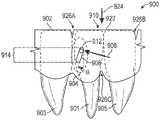
图9A、图9B和图9C示出示例性可移除牙科器具的颊侧视图,该可移除牙科器具包括壳体、与附接件接合的弹簧构件以及定位构件,用于促进患者牙齿的移动。Figures 9A, 9B, and 9C show buccal views of an exemplary removable dental appliance including a housing, a spring member engaged with an attachment, and a positioning member for facilitating the positioning of a patient's teeth move.

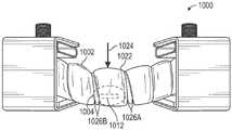
图10A和图10B示出示例性可移除牙科器具的颊侧视图,该可移除牙科器具包括定位构件和挠曲区域,用于促进弹簧构件与患者牙齿上的附接件的接合。10A and 10B illustrate buccal views of an exemplary removable dental appliance including a positioning member and a flexure region for facilitating engagement of a spring member with an attachment on a patient's teeth.

图11A和图11B示出示例性可移除牙科器具的颊侧视图,该可移除牙科器具包括定位构件和应力减低区域,用于促进弹簧构件与患者牙齿上的附接件的接合。11A and 11B illustrate buccal views of an exemplary removable dental appliance including a positioning member and a stress relief area for facilitating engagement of the spring member with an attachment on a patient's teeth.

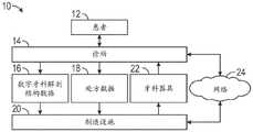
图12是示出示例性计算机环境的框图,在该示例性计算机环境中,诊所和制造设施在整个牙科器具制造过程中传送信息。12 is a block diagram illustrating an exemplary computer environment in which a clinic and a manufacturing facility communicate information throughout the dental appliance manufacturing process.

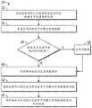
图13是示出生成数字牙齿结构数据的示例性过程的流程图。13 is a flowchart illustrating an exemplary process for generating digital tooth structure data.

图14是示出经由网络连接到制造设施以生成数字牙齿结构数据的客户端计算机的示例的框图。14 is a block diagram illustrating an example of a client computer connected to a manufacturing facility via a network to generate digital dental structure data.

图15是示出用于构造可移除牙科器具的示例性计算机辅助的制造系统的框图。15 is a block diagram illustrating an exemplary computer-aided manufacturing system for constructing a removable dental appliance.

图16是示出在制造设施处开展的用于构造一组可移除牙科器具的过程的流程图。16 is a flow chart illustrating a process carried out at a manufacturing facility for constructing a set of removable dental appliances.

图17是示出使用一组有序的可移除牙科器具进行的治疗的逐次迭代的流程图。17 is a flow chart illustrating successive iterations of treatment with an ordered set of removable dental appliances.

图18A和图18B示出可移除牙科器具的建模的弹簧构件的方向变形图和等效应力图。18A and 18B show directional deformation diagrams and equivalent stress diagrams of a modeled spring member of a removable dental appliance.

具体实施方式Detailed ways

本公开描述了可移除牙科器具以及制造所述可移除牙科器具的技术,所述可移除牙科器具包括器具主体,该器具主体包括形成在其中的定位构件,以促进该器具的弹簧构件与附连到牙齿的附接件的接合。该器具主体包括限定至少一个壳体的单一材料、弹簧构件和定位构件。该至少一个壳体的形状被成形为接纳患者的至少一颗牙齿并且将该至少一颗牙齿推向期望位置。期望位置可以在至少一颗牙齿的初始位置与由正畸治疗产生的最终位置之间。弹簧构件被构造成接纳附接件并向附接件施加力以移动附接件所附连的至少一颗牙齿。响应于定位力被施加到定位构件,定位构件促进弹簧构件与附接件的接合。当可移除牙科器具被放置在患者的牙齿上时,可以通过施加定位力来定位弹簧构件,以促进弹簧构件与附接件的接合。例如,弹簧构件或器具主体的其他部分可响应于定位力被施加到定位构件而变形,以致使弹簧构件接合附接件。例如,定位力可以由相对牙弓的咬合面施加。通过经由定位构件促进弹簧构件与附接件的接合,可移除牙科器具与其他正畸治疗相比可增加患者的顺从性,并且改善对力矢量方向,量值或两者的控制,以相比其他正畸器具在缩短的治疗时间内实现牙齿的期望移动。The present disclosure describes removable dental appliances and techniques for making the same that include an appliance body including a positioning member formed therein to facilitate a spring member of the appliance Engagement with attachments attached to teeth. The appliance body includes a single material defining at least one housing, a spring member, and a positioning member. The at least one housing is shaped to receive at least one tooth of the patient and urge the at least one tooth to a desired position. The desired position may be between the initial position of the at least one tooth and the final position resulting from the orthodontic treatment. The spring member is configured to receive the attachment and apply a force to the attachment to move at least one tooth to which the attachment is attached. In response to the positioning force being applied to the positioning member, the positioning member facilitates engagement of the spring member with the attachment. When the removable dental appliance is placed on the patient's teeth, the spring member may be positioned by applying a positioning force to facilitate engagement of the spring member with the attachment. For example, the spring member or other portion of the appliance body may deform in response to a positioning force being applied to the positioning member to cause the spring member to engage the attachment. For example, the positioning force may be exerted by the occlusal surface of the opposing dental arch. By facilitating engagement of the spring member with the attachment via the positioning member, the removable dental appliance may increase patient compliance compared to other orthodontic treatments and improve control over the direction, magnitude, or both of the force vector for relative The desired movement of the teeth is achieved in a shorter treatment time than other orthodontic appliances.

在一些示例中,通过将变形集中在弹簧构件中,相应的壳体可以保持与相应牙齿更高程度的接合。例如,当可移除牙科器具处于变形状态(例如,被患者佩戴)时,与不具有弹簧构件的可移除牙科器具相比,壳体可具有与相应牙齿的更多接触点、在相应牙齿上的更大接触表面积等。通过将力产生构件(弹簧构件)和接合构件(壳体)分开,可移除牙科器具可允许对施加到牙齿上的力进行更好的控制。In some examples, by concentrating the deformation in the spring member, the corresponding housing may maintain a higher degree of engagement with the corresponding tooth. For example, when the removable dental appliance is in a deformed state (eg, worn by a patient), the housing may have more points of contact with the corresponding teeth, at the corresponding teeth, than a removable dental appliance without a spring member larger contact surface area, etc. By separating the force-generating member (spring member) and engagement member (housing), the removable dental appliance may allow greater control over the force applied to the teeth.

附加地或另选地,弹簧构件可以被构造成向附接件施加弹簧力,以引起可能对于不包括弹簧构件的矫治器托盘更难以实现的牙齿移动,诸如旋转,外凸,内凸等。例如,附接件和弹簧构件可以被定位和成形为向患者的至少一颗牙齿提供特定的力矢量。弹簧力可以以一定方向或量值施加到附接件,在不具有附接件和弹簧构件的情况下不可能以该方向或量值施加到牙齿表面。以这种方式,弹簧构件的使用可以改善对力矢量方向、量值或两者的控制,以相比其他正畸器具在缩短的治疗时间内实现期望的牙齿移动。Additionally or alternatively, the spring member may be configured to apply a spring force to the attachment to induce movement of the teeth, such as rotation, convexity, convexity, etc., that may be more difficult to achieve with appliance trays that do not include spring members. For example, the attachment and spring member may be positioned and shaped to provide a specific force vector to at least one of the patient's teeth. The spring force may be applied to the attachment in a direction or magnitude that would not be possible to apply to the tooth surface without the attachment and the spring member. In this manner, the use of spring members can improve control of the force vector direction, magnitude, or both to achieve desired tooth movement in a reduced treatment time compared to other orthodontic appliances.

图1A至图1D示出示例性可移除牙科器具100的一部分的颊侧视图和横剖视图,该可移除牙科器具包括被构造成接合患者的牙齿101 上的附接件106的弹簧构件104。可移除牙科器具100可包括矫治器托盘,诸如透明托盘矫治器。图1A示出围绕患者的三颗前牙101、103 和105的可移除牙科器具100的一部分的颊侧视图,其中这三颗牙齿处于初始位置,例如错位咬合位置。图1B示出围绕患者的三颗前牙 101、103和105的可移除牙科器具100的一部分的颊侧视图,其中这三颗牙齿处于期望位置,例如,正畸治疗之后的最终位置或通过使用可移除牙科器具100实现的中间位置。图1C示出围绕前牙101的可移除牙科器具100的一部分的横剖视图,其中牙齿101处于初始位置。图1D示出围绕前牙101的可移除牙科器具100的一部分的横剖视图,其中牙齿101处于期望位置。FIGS. 1A-1D show buccal and cross-sectional views of a portion of an exemplary removabledental appliance 100 including aspring member 104 configured to engage anattachment 106 on a patient'steeth 101 . Removabledental appliance 100 may include appliance trays, such as clear tray appliances. Figure 1A shows a buccal view of a portion of a removabledental appliance 100 surrounding a patient's threefront teeth 101, 103, and 105 in an initial position, eg, an out-of-bite position. Figure IB shows a buccal view of a portion of the removabledental appliance 100 surrounding the patient's threefront teeth 101, 103, and 105 in a desired position, eg, a final position after orthodontic treatment or through An intermediate position achieved using the removabledental appliance 100 . Figure 1C shows a cross-sectional view of a portion of the removabledental appliance 100 around thefront teeth 101, with theteeth 101 in the initial position. Figure ID shows a cross-sectional view of a portion of the removabledental appliance 100 around thefront teeth 101 with theteeth 101 in the desired position.

可移除牙科器具100包括器具主体102。器具主体102被构造成至少部分地围绕患者的上颌牙弓或下颌牙弓的多颗牙齿。多颗牙齿可包括前牙、后牙或其部分或组合。Removabledental appliance 100 includesappliance body 102 . Theappliance body 102 is configured to at least partially surround a plurality of teeth of a patient's maxillary or mandibular dental arch. The plurality of teeth may include anterior teeth, posterior teeth, or portions or combinations thereof.

器具主体102包括至少一个壳体110。在一些示例中,该至少一个壳体110可以围绕牙齿的颊侧、舌侧和咬合部分。在其他示例中,至少一个壳体110可围绕一颗或多颗牙齿的较少部分,例如,仅颊侧和舌侧部分,或者仅颊侧、舌侧或咬合部分中的一者。至少一个壳体110可以被成形为对应于至少一颗牙齿(例如,牙齿101、牙齿103或牙齿105中的一颗或多颗)的期望位置,例如,与至少一颗牙齿的当前位置不同的最终位置或中间位置。例如,如图1A和图1C所示,壳体110可以包括表面111,该表面限定壳体110内部的空隙,并且可以被成形为接纳牙齿101的至少一部分(例如,至少一个表面)。Theappliance body 102 includes at least onehousing 110 . In some examples, the at least onehousing 110 may surround the buccal, lingual, and occlusal portions of the teeth. In other examples, at least onehousing 110 may surround a smaller portion of one or more teeth, eg, only the buccal and lingual portions, or only one of the buccal, lingual, or occlusal portions. The at least onehousing 110 may be shaped to correspond to a desired position of the at least one tooth (eg, one or more of thetooth 101 , thetooth 103 , or the tooth 105 ), eg, different from the current position of the at least one tooth final or intermediate position. For example, as shown in FIGS. 1A and 1C , thehousing 110 may include asurface 111 that defines a void within thehousing 110 and may be shaped to receive at least a portion (eg, at least one surface) of thetooth 101 .

在正畸治疗期间,壳体110和表面111可以限定牙齿101的移动极限。例如,当牙齿101被外凸时,牙齿101可移动通过由表面111 限定的空隙。当牙齿101接触表面111的至少一部分时,牙齿101可停止移动,这也可以对应于由弹簧构件104施加的弹簧力108下降到低于引起牙齿101移动所需的阈值力的位置。在一些示例中,如果牙齿101仅一部分接触表面111,而在其他地方保留有间隙,则可以在与表面111的接触点和弹簧力108之间形成联接。所产生的联接可引起牙齿101移动到与表面111更对准的位置。例如,牙齿101可以在交替平移和旋转的阶段中移动,直到牙齿101被完全接纳在与表面111 一致的位置。以这种方式,选择壳体110和表面111的形状可以使得能够控制力的位置以及牙齿101的所产生的移动。During orthodontic treatment, thehousing 110 andsurface 111 may define the limits of movement of theteeth 101 . For example, whentooth 101 is convexed,tooth 101 can move through the void defined bysurface 111 . Thetooth 101 may stop moving when thetooth 101 contacts at least a portion of thesurface 111, which may also correspond to a position where thespring force 108 applied by thespring member 104 falls below the threshold force required to cause thetooth 101 to move. In some examples, if only a portion of thetooth 101 contacts thesurface 111 , while leaving a gap elsewhere, a coupling may be formed between the point of contact with thesurface 111 and thespring force 108 . The resulting coupling can cause thetooth 101 to move into a position that is more aligned with thesurface 111 . For example, thetooth 101 may be moved in phases of alternating translation and rotation until thetooth 101 is fully received in line with thesurface 111 . In this way, selecting the shape of thehousing 110 and thesurface 111 can enable control of the location of the force and the resulting movement of thetooth 101 .

器具主体102包括至少一个弹簧构件104,该至少一个弹簧构件被构造成接合附接件106。在一些示例中,附接件106附连到牙齿101 上,以提供可在其上施加力的抓握点诸如底切、突出部、旋钮、柄部等。在其他示例中,自然底切或抓握点诸如牙齿的高度弯曲部分(包括但不限于尖头顶端或颈部轮廓)可以限定附接件106。一般来讲,可以选择附接件106以促进器具主体102在患者的牙弓上的接合和固定。例如,附接件106可以限定倾斜形状,例如三角形形状,其具有附连到牙齿的第一表面、大致垂直于牙齿表面延伸的第二表面、以及从牙齿表面以一定角度延伸到第二表面的第三表面(例如,斜面)。倾斜附接件可以包括任何合适的形状。弹簧构件104与倾斜附接件的接合可以由壳体110在弹簧构件的至少一部分在倾斜附接件106的第二表面上行进时的变形以及壳体110在凹槽112接合倾斜附接件的至少一部分时的至少部分松弛而产生。在一些示例中,凹槽112可部分地接合倾斜附接件,使得当器具主体朝向未变形构型移动时凹槽112沿斜面向下行进。Theappliance body 102 includes at least onespring member 104 configured to engage theattachment 106 . In some examples, theattachments 106 are attached to theteeth 101 to provide gripping points such as undercuts, protrusions, knobs, handles, etc. on which forces can be applied. In other examples, natural undercuts or grip points such as highly curved portions of teeth (including but not limited to pointed tips or neck contours) may defineattachments 106 . In general, theattachments 106 may be selected to facilitate engagement and fixation of theappliance body 102 on the patient's dental arch. For example, theattachment 106 may define an inclined shape, such as a triangular shape, having a first surface attached to the tooth, a second surface extending generally perpendicular to the tooth surface, and a second surface extending at an angle from the tooth surface to the second surface A third surface (eg, bevel). The angled attachment may comprise any suitable shape. Engagement of thespring member 104 with the angled attachment may be caused by deformation of thehousing 110 as at least a portion of the spring member travels over the second surface of theangled attachment 106 and by thehousing 110 engaging the angled attachment at thegroove 112 . Produced by at least partial relaxation of at least a portion of the time. In some examples, thegrooves 112 may partially engage the angled attachment such that thegrooves 112 travel down the slope as the appliance body is moved toward the undeformed configuration.

选择第一和第二倾斜附接件106的形状可以控制弹簧力108的表现的量值或长度,并且可以控制牙齿移动。例如,倾斜附接件的大小可能会影响弹簧力108的量值。例如,增加倾斜附接件的尺寸(例如,前庭-舌侧尺寸)可导致壳体110的较大变形以及弹簧力108较大量值。相反,较小的倾斜附接件导致壳体110的较小变形以及弹簧力108较小量值。类似地,相对于垂直于牙齿表面的平面具有更锐化角度的倾斜附接件可以减小倾斜附接件与弹簧构件104之间的摩擦,以将更多的弹簧力108传递到牙齿101。然而,具有更锐化角度的倾斜附接件可减小力的表现的总长度,例如,与不太锐化的斜坡形状相比,更锐化的斜坡形状可能不会使牙齿101移动的更远。通过选择倾斜附接件的形状,可移除牙科器具100可以控制弹簧力108的表现的量值和长度。Selecting the shape of the first and secondangled attachments 106 can control the magnitude or length of thespring force 108 manifestation, and can control tooth movement. For example, the size of the angled attachment may affect the magnitude of thespring force 108 . For example, increasing the size of the angled attachment (eg, vestibular-lingual size) may result in a larger deformation of thehousing 110 and a larger magnitude of thespring force 108 . Conversely, a smaller angled attachment results in a smaller deformation of thehousing 110 and a smaller magnitude of thespring force 108 . Similarly, an angled attachment with a sharper angle relative to a plane normal to the tooth surface may reduce friction between the angled attachment and thespring member 104 to transmit more of thespring force 108 to thetooth 101 . However, angled attachments with sharper angles may reduce the overall length of the force manifestation, eg, a sharper ramp shape may not move thetooth 101 any more than a less sharp ramp shape. Far. By selecting the shape of the angled attachment, the removabledental appliance 100 can control the magnitude and length of thespring force 108 manifestation.

选择倾斜附接件的取向可以控制弹簧力108的方向,并且可以控制牙齿移动。例如,使倾斜附接件的倾斜面朝向牙齿101的咬合面取向可导致内凸。作为另一示例,使倾斜附接件的倾斜面相对于牙齿101 朝向近中或远侧方向取向可导致平移或倾斜。通过选择倾斜附接件的数量,一个或多个倾斜附接件的取向,一个或多个倾斜附接件与相应的弹簧构件的接合位置以及壳体110的形状,可移除牙科器具100可以被构造成控制施加到牙齿101的力的方向。Selecting the orientation of the angled attachment can control the direction of thespring force 108, and can control tooth movement. For example, orienting the inclined surface of the inclined attachment towards the occlusal surface of thetooth 101 may result in a convexity. As another example, orienting the inclined surface of the inclined attachment in a mesial or distal direction relative to thetooth 101 may result in translation or inclination. By selecting the number of angled attachments, the orientation of the one or more angled attachments, the engagement locations of the one or more angled attachments with the corresponding spring members, and the shape of thehousing 110, the removabledental appliance 100 can be is configured to control the direction of the force applied to thetooth 101 .

在一些示例中,弹簧构件104与至少一个壳体110成一体。弹簧构件104可包括器具主体102的在弹簧构件104与附接件106接合时可变形的区域。例如,弹簧构件104可以包括由图4A和图4C中的虚线指示的区域。在其他示例中,弹簧构件104包括与器具主体102一体形成以从铰链轴延伸的可弯曲翼片(例如,悬臂梁)。一般来讲,相应的可弯曲翼片可以从沿相应壳体的任何部分延伸的相应铰链轴在任何方向上延伸。例如,可弯曲翼片可以从靠近器具主体102的咬合部分的铰链轴延伸。器具主体102可以限定翼片边界区域,该翼片边界区域从铰链轴上的第一端点(围绕可弯曲翼片)延伸到铰链轴上的第二端点。与器具主体102的周围部分相比,翼边界区域可包括剪切应力和拉伸应力减小的区域,例如切口、狭缝、多个穿孔、弹性体材料、低模量材料、至少一个弓形位移和器具主体102的较薄区域中的至少一者。至少一个弓形位移可以包括例如围绕翼片边界区域109C的至少一部分延伸的弹簧波纹管(例如,材料带)或联接到壳体和可弯曲翼片的至少一个跨接片(例如,材料棒)。弓形位移可以由与壳体相同的材料制成,并且形状可以是弓形、正弦曲线形、锯齿形或其他折叠横截面(在与相切于翼片边界区域的平面和壳体的表面两者垂直的平面中)中的至少一者。该弓形位移可以与壳体104C一体形成。通过包括剪切应力和拉伸应力减低的区域,翼片边界区域可允许可弯曲翼片在舌侧方向上偏转,覆盖翼片边界区域的至少一部分以减少食物颗粒或牙菌斑在翼片边界区域或器具主体102的其他部分或两者中的累积。In some examples, thespring member 104 is integral with the at least onehousing 110 . Thespring member 104 may include a region of theappliance body 102 that is deformable when thespring member 104 is engaged with theattachment 106 . For example, thespring member 104 may include the area indicated by the dashed lines in Figures 4A and 4C. In other examples, thespring member 104 includes a flexible tab (eg, a cantilever beam) integrally formed with theappliance body 102 to extend from the hinge axis. In general, the respective bendable tabs may extend in any direction from respective hinge axes extending along any portion of the respective housing. For example, the bendable tabs may extend from the hinge axis proximate the bite portion of theappliance body 102 . Theappliance body 102 may define a fin boundary region extending from a first end point on the hinge axis (around the bendable fin) to a second end point on the hinge axis. The wing boundary region may include areas of reduced shear and tensile stress compared to the surrounding portion of theappliance body 102, such as cuts, slits, multiple perforations, elastomeric materials, low modulus materials, at least one arcuate displacement and at least one of the thinner regions of theappliance body 102 . The at least one arcuate displacement may include, for example, a spring bellows (eg, a strip of material) extending around at least a portion of the fin boundary region 109C or at least one bridge piece (eg, a bar of material) coupled to the housing and the flexible fins. The arcuate displacement can be made of the same material as the shell, and the shape can be arcuate, sinusoidal, zigzag, or other folded cross-section (at right angles to both the plane tangent to the boundary area of the fin and the surface of the shell). at least one of the planes). The arcuate displacement may be integrally formed with the housing 104C. By including regions of reduced shear stress and tensile stress, the flap boundary region may allow deflection of the flexible flap in a lingual direction, covering at least a portion of the flap boundary region to reduce food particles or plaque at the flap boundary An accumulation in a region or other portion of theappliance body 102 or both.

弹簧构件104可包括凹槽112以与附接件106接合。凹槽112可以被定位和成形为接纳附接件106的至少一部分。例如,器具主体102 包括限定凹槽112的凹陷部,凹槽112可以延伸到器具主体102的至少一部分中,凹槽112可以基本上延伸穿过器具主体102等。在其中凹槽112基本上延伸穿过器具主体102的示例中,器具主体102可以包括被构造成至少部分地在凹槽112上延伸的弹簧构件盖。弹簧构件盖可以减少食物颗粒或牙斑块在凹槽112中的累积。弹簧构件盖可以包括与器具主体102相同的材料,或者不同的、优选较低模量的材料。包括较低模量材料的弹簧构件盖可以被构造成覆盖基本上延伸穿过器具主体102的凹槽112,并且当弹簧构件104变形时容易地变形。凹槽 112可以使弹簧构件104能够与附接件106接合。Thespring member 104 may include agroove 112 to engage with theattachment 106 . Thegroove 112 may be positioned and shaped to receive at least a portion of theattachment 106 . For example, theappliance body 102 includes a recess that defines agroove 112, thegroove 112 can extend into at least a portion of theappliance body 102, thegroove 112 can extend substantially through theappliance body 102, and the like. In examples in which thegroove 112 extends substantially through theappliance body 102 , theappliance body 102 may include a spring member cover configured to extend at least partially over thegroove 112 . The spring member cover may reduce the accumulation of food particles or plaque in thegrooves 112 . The spring member cover may comprise the same material as theappliance body 102, or a different, preferably lower modulus material. A spring member cover comprising a lower modulus material may be configured to cover thegroove 112 extending substantially through theappliance body 102 and readily deform when thespring member 104 is deformed. Thegroove 112 may enable thespring member 104 to engage with theattachment 106.

凹槽112可以被定位和成形为遵循可移除牙科器具100的齿龈边缘。例如,凹槽112可以从可移除牙科器具100的边缘经受恒定的偏移。以这种方式,器具主体102可以限定具有恒定高度和厚度两者的材料条带(例如,弹簧构件104的齿龈部分)。在一些示例中,条带的横截面的长径比可以减小,使得条带的高度基本上等于或小于条带的厚度。条带的形状和位置可被选择为实现以下效果中的至少一种:减小条带变形时条带中的扭转;通过减小条带沿其长度的横截面积改善条带在张紧状态下的弹性;以及通过遵循齿龈边缘的弓形或正弦曲线路径来改善条带的弹性。Thegrooves 112 may be positioned and shaped to follow the gingival margin of the removabledental appliance 100 . For example, thegrooves 112 may experience a constant offset from the edge of the removabledental appliance 100 . In this manner, theappliance body 102 may define a strip of material (eg, the gingival portion of the spring member 104) having both a constant height and thickness. In some examples, the aspect ratio of the cross-section of the strip can be reduced such that the height of the strip is substantially equal to or less than the thickness of the strip. The shape and position of the straps may be selected to achieve at least one of: reducing twist in the straps when the straps are deformed; improving the straps in tension by reducing the cross-sectional area of the straps along its length elasticity under the gum; and improving the elasticity of the strip by following an arcuate or sinusoidal path at the gingival margin.

在其中弹簧构件104包括可弯曲翼片的示例中,可弯曲翼片可包括靠近翼片的与铰链轴相对的边缘(例如,可弯曲翼片的自由端)的凹槽112。例如,粘结在齿龈边缘附近的附接件106可包括在齿龈侧上的底切,该底切被构造成与在可弯曲翼片的自由端附近的凹槽112接合,该可弯曲翼片从靠近器具主体102的咬合部分的铰链轴延伸。可弯曲翼片可包括沿着可弯曲翼片的咬合端部和齿龈端部之间的中间区段的至少第二铰链轴。第二铰链轴可以平行于第一铰链轴。第一铰链轴和第二铰链轴导致可弯曲翼片在静止位置时的波形或锯齿形构造。例如,第一铰链轴可以导致可弯曲翼片在静止位置的颊侧位移,而第二铰链轴可以导致可弯曲翼片在静止位置的舌侧位移。可弯曲翼片可被构造成在可弯曲翼片变形以使凹槽112与附接件106接合时变直成更平坦的构造。可弯曲翼片的齿龈边缘可略微倾斜或上翻,附接件106 的咬合边缘可以倾斜,或两者均倾斜,以在可弯曲翼片变形以使凹槽 112与附接件106接合时减少当可弯曲翼片的齿龈边缘在附接件106的咬合边缘上行进时的冲突。例如,响应于施加到可弯曲翼片的力(例如,在颊侧至舌侧方向上朝向牙齿的颊侧表面的手指压力),可弯曲翼片展开或变平以在齿龈方向上延伸,以使凹槽112与附接件106对准,并且附加的力可用于使凹槽112与附接件106接合。指甲或辅助工具可用于提起可弯曲翼片以使凹槽112与附接件106脱离接合。In examples in which thespring member 104 includes a bendable flap, the bendable flap may include agroove 112 near the edge of the flap opposite the hinge axis (eg, the free end of the bendable flap). For example, theattachment 106 bonded near the gingival edge may include an undercut on the gingival side that is configured to engage thegroove 112 near the free end of the flexible flap that is Extends from the hinge axis near the bite portion of theappliance body 102 . The bendable flap may include at least a second hinge axis along an intermediate section between the occlusal end and the gingival end of the bendable flap. The second hinge axis may be parallel to the first hinge axis. The first hinge axis and the second hinge axis result in a wavy or sawtooth configuration of the bendable flap in the rest position. For example, a first hinge axis may cause buccal displacement of the bendable flap in the rest position, while a second hinge axis may cause lingual displacement of the bendable flap in the rest position. The bendable tabs may be configured to straighten into a flatter configuration as the bendable tabs deform to engage thegrooves 112 with theattachments 106 . The gingival edges of the flexible tabs can be slightly sloped or turned up, the bite edges of theattachments 106 can be sloped, or both, to reduce when the flexible tabs deform to engage thegrooves 112 with theattachments 106 Conflict when the gingival edge of the flexible flap travels over the occlusal edge of theattachment 106 . For example, in response to a force applied to the flexible fins (eg, finger pressure toward the buccal surface of the tooth in a buccal-lingual direction), the flexible fins expand or flatten to extend in the gingival direction to Thegroove 112 is aligned with theattachment 106 and additional force may be used to engage thegroove 112 with theattachment 106 . A fingernail or an aid may be used to lift the flexible tabs to disengage thegrooves 112 from theattachments 106 .

如图1A和图1B所示,凹槽112可以包括基本上垂直于弹簧力108 的方向延伸的第一尺寸114和基本上平行于弹簧力108的方向延伸的第二尺寸116。在一些示例中,第一尺寸114可以大于第二尺寸116。例如,凹槽112可被成形为细长狭槽、椭圆形、矩形等。在其他示例中,第一尺寸114和第二尺寸可以基本上类似。例如,凹槽112可以被成形为圆形、正方形等。在其他示例中,凹槽112可以包括其他规则或不规则形状。凹槽112可以包含用于防止附接件(及其对应的牙齿)在狭槽中的不期望的移动(例如,横向漂移)的特征部,诸如突出部或凹口。在一些示例中,凹槽112可以包括至少一个(诸如两个) 应力集中降低特征部。例如,凹槽112的端部可包括应力集中降低圆。当弹簧构件104变形以与附接件106接合时,应力集中降低特征部可以减少器具主体102的撕裂或破裂。As shown in FIGS. 1A and 1B , thegroove 112 may include afirst dimension 114 extending substantially perpendicular to the direction of thespring force 108 and a second dimension 116 extending substantially parallel to the direction of thespring force 108 . In some examples, thefirst dimension 114 may be larger than the second dimension 116 . For example, thegrooves 112 may be shaped as elongated slots, ovals, rectangles, or the like. In other examples, thefirst dimension 114 and the second dimension may be substantially similar. For example, thegrooves 112 may be shaped as circles, squares, or the like. In other examples,grooves 112 may include other regular or irregular shapes. Thegrooves 112 may include features, such as protrusions or notches, for preventing unwanted movement (eg, lateral drift) of the attachment (and its corresponding teeth) in the slot. In some examples, groove 112 may include at least one (such as two) stress concentration reducing features. For example, the ends of thegrooves 112 may include stress concentration reducing circles. The stress concentration reducing features may reduce tearing or cracking of theappliance body 102 as thespring member 104 deforms to engage theattachment 106 .

在一些示例中,凹槽112相对于附接件106的形状和位置可影响弹簧力108的方向或量值。例如,当器具主体102处于未变形状态时,凹槽112可定位成远离附接件106,使得当器具主体102变形以使弹簧构件104与附接件106接合时,弹簧构件104向附接件106施加更大量的力。作为另一个示例,凹槽112的第一尺寸114可以被定位成平行于牙齿的咬合平面(例如,如图4A和图4B所示)。通过将第一尺寸114定位成平行于牙齿的咬合平面,弹簧构件104可以在附接件106 上施加基本上垂直于咬合平面的弹簧力108,以在附接件106上产生力,这可在可移除牙科器具100被患者佩戴时对牙齿101产生基本上外凸 (或内凸)的力,具体取决于在未变形状态下弹簧构件104位于附接件106的咬合侧还是齿龈侧。作为另外的示例,凹槽112的第一尺寸 114可以相对于牙齿的咬合平面成一定角度定位,以向附接件106提供力,该力可以引起牙齿101上的旋转、平移、外凸、内凸、倾斜或扭转力中的至少一者。In some examples, the shape and location ofgroove 112 relative toattachment 106 may affect the direction or magnitude ofspring force 108 . For example, when theappliance body 102 is in the undeformed state, thegroove 112 may be positioned away from theattachment 106 such that when theappliance body 102 is deformed to engage thespring member 104 with theattachment 106, thespring member 104 moves toward theattachment 106 applies a greater amount of force. As another example, thefirst dimension 114 of thegroove 112 may be positioned parallel to the occlusal plane of the teeth (eg, as shown in FIGS. 4A and 4B ). By positioning thefirst dimension 114 parallel to the occlusal plane of the teeth, thespring member 104 can exert aspring force 108 on theattachment 106 substantially perpendicular to the occlusal plane to create a force on theattachment 106, which can be Depending on whether thespring member 104 is on the occlusal or gingival side of theattachment 106 in the undeformed state, the removabledental appliance 100 exerts a substantially convex (or convex) force on theteeth 101 when worn by a patient. As a further example, thefirst dimension 114 of thegroove 112 can be positioned at an angle relative to the occlusal plane of the tooth to provide a force to theattachment 106 that can cause rotation, translation, convexity, concavity on thetooth 101 At least one of convex, tilted, or torsional forces.

在其他示例中,弹簧构件104可以包括从器具主体102朝向牙齿 101的表面向外延伸的突出部,而非凹槽112。突出部可以被构造成接合附接件106。例如,突出部可以包括被成形为接合附接件106的凸缘。突出部可以被成形、定位或包括尺寸,以控制施加到附接件106的力 108的方向、量值或两者,如上面关于凹槽112所述。In other examples, instead ofgrooves 112,spring member 104 may include protrusions extending outwardly from the surface ofappliance body 102 towardteeth 101. The protrusions may be configured to engage theattachment 106 . For example, the protrusions may include flanges shaped to engage theattachments 106 . The protrusions may be shaped, positioned, or sized to control the direction, magnitude, or both of theforce 108 applied to theattachment 106, as described above with respect to thegrooves 112.

在一些示例中,当弹簧构件104初始接合附接件106时,器具主体102的至少一部分,例如弹簧构件104的至少一部分可能会变形。通过使器具主体102的至少一部分变形,弹簧构件104可以将弹簧力 108施加到附接件106。例如,弹簧力108至少部分地源自弹簧构件104 的变形(例如,偏转),该弹簧构件包括在器具主体102的边缘与凹槽112之间延伸的器具主体102的条带。弹簧构件104的长径比可以较高,例如,弹簧构件104的高度(即在咬合齿龈方向上)可以比其宽度(即在唇舌方向上)大得多。当弹簧构件104变形以与附接件106 接合时,弹簧构件104可以从咬合齿龈平面移位。例如,除了在咬合齿龈方向上弯曲之外,弹簧构件104还可以在唇舌方向上远离牙齿扭曲。在一些示例中,弹簧构件104的咬合边缘通过在附接件106上的底切保持固定。弹簧构件104的边缘在其扭曲时可以抵靠附接件106 旋转至多90度或更大。弹簧构件104的扭曲可以在附接件106上产生力,该力至少部分地贡献弹簧力108的所产生的量值、弹簧力108的方向或两者。另外,弹簧构件104的至少一部分可以处于张紧状态。弹簧构件104的张紧可以在附接件106上产生力,该力至少部分地贡献弹簧力108的所产生的量值、弹簧力108的方向或两者。这样,弹簧构件104可以被构造成将具有特定方向和量值的弹簧力108施加到附接件106。弹簧力108可导致牙齿101上的对应旋转力、平移力、外凸力、内凸力、倾斜力或扭转力中的任何一者或多者。通过经由弹簧构件104的变形施加力108,与不具有弹簧构件104的CTA相比,与壳体110相邻的相应壳体可以更好地接合相应的牙齿。这样,可移除牙科器具100可以使相应牙齿与相应壳体的接合以及施加到相应牙齿的力脱离,以改善对力矢量方向、量值或两者的控制,从而相比不具有弹簧构件104的CTA在缩短的治疗时间内实现期望的牙齿移动。附加地或另选地,弹簧构件104可被构造成将弹簧力施加到附接件106 以引起牙齿101的一种或多种移动诸如旋转、外凸、内凸等,一种或多种移动对于不包括弹簧构件104的矫治器托盘可能更难实现。In some examples, when thespring member 104 initially engages theattachment 106, at least a portion of theappliance body 102, eg, at least a portion of thespring member 104, may deform. By deforming at least a portion of theappliance body 102, thespring member 104 may apply aspring force 108 to theattachment 106. For example, thespring force 108 results at least in part from the deformation (eg, deflection) of thespring member 104 , which includes a strap of theappliance body 102 extending between the edge of theappliance body 102 and thegroove 112 . The aspect ratio of thespring member 104 may be high, eg, the height of the spring member 104 (ie in the occlusal direction) may be much greater than its width (ie in the labial direction). When thespring member 104 is deformed into engagement with theattachment 106, thespring member 104 can be displaced from the occlusal gingival plane. For example, in addition to bending in the occlusal gingival direction, thespring member 104 may also twist away from the teeth in the labial and lingual direction. In some examples, the snapping edge of thespring member 104 is held in place by an undercut on theattachment 106 . The edge of thespring member 104 may rotate up to 90 degrees or more against theattachment 106 as it twists. Twisting of thespring member 104 may generate a force on theattachment 106 that contributes at least in part to the magnitude of the resultingspring force 108 , the direction of thespring force 108 , or both. Additionally, at least a portion of thespring member 104 may be in tension. The tensioning of thespring member 104 may generate a force on theattachment 106 that contributes at least in part to the magnitude of the resultingspring force 108 , the direction of thespring force 108 , or both. As such, thespring member 104 may be configured to apply aspring force 108 having a particular direction and magnitude to theattachment 106 . Thespring force 108 may cause any one or more of a corresponding rotational force, translational force, convexity force, convexity force, tilting force, or torsional force on thetooth 101 . By applying theforce 108 via the deformation of thespring member 104 , the respective housing adjacent to thehousing 110 may better engage the respective tooth than a CTA without thespring member 104 . In this way, the removabledental appliance 100 can disengage the engagement of the respective teeth with the respective housings and the force applied to the respective teeth to improve control of the force vector direction, magnitude, or both, compared to without thespring member 104 The CTA achieves the desired tooth movement in a shortened treatment time. Additionally or alternatively, thespring member 104 may be configured to apply a spring force to theattachment 106 to cause one or more movements of thetooth 101 such as rotation, camber, camber, etc., one or more movements This may be more difficult to implement for appliance trays that do not includespring members 104 .

器具主体102可包括聚合物材料诸如任何一种或多种合适的聚合物。合适的聚合物可包括但不限于:(甲基)丙烯酸酯合物;环氧树脂、有机硅;聚酯;聚氨酯;聚碳酸酯;巯基-乙烯基聚合物;丙烯酸酯聚合物,诸如氨基甲酸酯(甲基)丙烯酸酯聚合物、聚环氧烷二(甲基)丙烯酸酯、烷烃二醇二(甲基)丙烯酸酯、脂族(甲基)丙烯酸酯、硅氧烷(甲基) 丙烯酸酯;聚对苯二甲酸乙二醇酯基聚合物,诸如聚对苯二甲酸乙二醇酯(PETG);聚丙烯;乙烯-乙酸乙烯酯;等等。在一些示例中,器具主体102可以包括单一聚合物材料,该单一聚合物材料形成器具主体102的至少一个壳体110、弹簧构件104和定位构件。例如,可移除牙科器具100可以包括单种连续聚合物材料。在其他示例中,器具主体102可以包括多层材料。多层材料可以包括多层的单种材料例如单种聚合物,或多层的多种材料例如两种或更多种聚合物、聚合物和另一种材料。多层材料可使器具主体102的一个或多个部分能够由具有不同弹性模量的多个层形成,以使得能够选择弹簧构件104的力特性。Theappliance body 102 may comprise a polymeric material such as any one or more suitable polymers. Suitable polymers may include, but are not limited to: (meth)acrylates; epoxies, silicones; polyesters; polyurethanes; polycarbonates; mercapto-vinyl polymers; acrylate polymers such as urethane Ester (meth)acrylate polymers, polyalkylene oxide di(meth)acrylates, alkanediol di(meth)acrylates, aliphatic (meth)acrylates, silicone (meth)acrylates Acrylates; polyethylene terephthalate based polymers such as polyethylene terephthalate (PETG); polypropylene; ethylene vinyl acetate; In some examples, theappliance body 102 may include a single polymeric material that forms at least one of thehousing 110 , thespring member 104 and the positioning member of theappliance body 102 . For example, the removabledental appliance 100 may comprise a single continuous polymeric material. In other examples, theappliance body 102 may include multiple layers of material. A multilayer material may include multiple layers of a single material such as a single polymer, or multiple layers of multiple materials such as two or more polymers, a polymer and another material. Multiple layers of material may enable one or more portions of theappliance body 102 to be formed from multiple layers having different elastic moduli to enable the force characteristics of thespring member 104 to be selected.

可使用任何合适的技术将器具主体102形成为期望的形状。在一些示例中,可以使用热成型模具工艺将器具主体102形成为患者牙齿的期望位置的形状。例如,患者牙科解剖结构的至少一部分的模具塞或阳性模型可使用合适的技术形成,诸如通过3D打印、铣削、浇注印模浇铸或者在蜡中设定分段齿,其中牙齿的位置被设定到下一个增量位置。模具塞或阳性模型可包括附接件106的类似物,其导致在器具主体102中形成凹陷、在器具主体102中形成引导件等。例如,类似物可以复制附接件106的至少一个特征部,可以从附接件106的实际表面偏移或缩放以在托盘中留出空间用于在托盘被安置在患者的牙齿上时接纳实际附接件,可以添加或省略特征部(例如,底切)等。作为另一个示例,该类似物可以产生可用于手动或自动地在器具主体102 中切割或蚀刻凹槽112的引导件。用于形成器具主体102的材料的片材可被加热至其玻璃化转变温度(或以上),在牙齿模型上悬垂并经受空气压差,使得比与模型相邻的内表面向片材的外表面施加更高的压力。压差使片材适形于牙齿模型的表面,并且通过保持压差直至片材冷却至低于其玻璃化转变温度来保持形状。在冷却期间或之后,可手动或自动地(例如,通过CNC铣削、激光加工等)修整器具主体102 以形成至少一个凹槽112和至少一个弹簧构件104中的至少一者。Theappliance body 102 may be formed into the desired shape using any suitable technique. In some examples, theappliance body 102 may be formed into the shape of the desired location of the patient's teeth using a thermoforming mold process. For example, a mold plug or male model of at least a portion of a patient's dental anatomy may be formed using a suitable technique, such as by 3D printing, milling, cast impression casting, or setting segmented teeth in wax, where the position of the teeth is set to the next incremental position. A mold plug or male mold may include the like forattachments 106 that cause depressions to be formed in theappliance body 102, guides to be formed in theappliance body 102, and the like. For example, the analog may replicate at least one feature of theattachment 106, may be offset or scaled from the actual surface of theattachment 106 to leave room in the tray for receiving the actual tray when placed on the patient's teeth Attachments, features (eg, undercuts), etc. may be added or omitted. As another example, the like can create a guide that can be used to cut oretch grooves 112 in theappliance body 102, either manually or automatically. The sheet of material used to form theappliance body 102 may be heated to its glass transition temperature (or above), draped over the dental model and subjected to an air pressure differential such that the outer surface of the sheet is more oriented than the inner surface adjacent to the model. Apply higher pressure to the surface. The pressure differential conforms the sheet to the surface of the dental model and maintains shape by maintaining the pressure differential until the sheet cools below its glass transition temperature. During or after cooling, theappliance body 102 may be trimmed manually or automatically (eg, by CNC milling, laser machining, etc.) to form at least one of the at least onegroove 112 and the at least onespring member 104 .

在其他示例中,三维(3D)打印或增材制造可用于形成器具主体 102。例如,可使用例如口内扫描仪来产生患者的牙齿的数字3D表示。然后可基于牙齿的期望位置的数字表示使用3D打印机直接制备器具主体102。3D打印工艺可产生由轮廓线或“梯级台阶”(也称为混叠效应)标记的纹理化表面,这在口腔应用中由于感官感觉差而不太理想。由于混叠,通过3D打印形成的器具主体102可散射光并降低聚合物材料的透明度、允许生物膜形成或牙齿变色,并且增加与牙列中的相对表面的摩擦或干涉。另外,一些3D打印聚合物可能在口腔环境中降解。为了减少这些影响,可以以多种方式对通过3D打印形成的器具主体102进行后处理(包括用一种或多种涂层进行涂覆),以影响主体的表面形态。例如,可用Parkar等人的标题为“WATER-RESISTANT POLYMER-BASED DENTAL ARTICLES”的共同未决的美国专利申请62/536,719中所述的防水聚合物涂覆可移除牙科器具,该专利申请的内容通过引用方式整体并入本文。In other examples, three-dimensional (3D) printing or additive manufacturing may be used to form theappliance body 102. For example, a digital 3D representation of the patient's teeth may be generated using, for example, an intraoral scanner. Theappliance body 102 can then be fabricated directly using a 3D printer based on a digital representation of the desired position of the teeth. The 3D printing process can produce a textured surface marked by contour lines or "steps" (also known as aliasing effects), which are useful in oral applications Moderate is not ideal due to poor sensory perception. Due to aliasing, theappliance body 102 formed by 3D printing can scatter light and reduce the transparency of polymeric materials, allow biofilm formation or tooth discoloration, and increase friction or interference with opposing surfaces in the dentition. Additionally, some 3D printed polymers may degrade in the oral environment. To reduce these effects, theappliance body 102 formed by 3D printing can be post-processed in a variety of ways, including coating with one or more coatings, to affect the surface morphology of the body. For example, removable dental appliances can be coated with the water-resistant polymers described in copendingUS Patent Application 62/536,719 to Parkar et al., entitled "WATER-RESISTANT POLYMER-BASED DENTAL ARTICLES," the contents of which Incorporated herein by reference in its entirety.

可移除牙科器具100的厚度可以在约0.10毫米至约2.0毫米之间,诸如在约0.2毫米至约1.0毫米之间,或者在约0.3毫米至约0.75毫米之间。在一些示例中,可以改变限定可移除牙科器具100的特征部的器具主体102的厚度以实现更合适的定制力,这些特征部包括但不限于弹簧构件104、壳体110、表面111或凹槽112。例如,器具主体102 的厚度可以在弹簧构件104附近或之中增加。对于弹簧构件104与附接件106接合所需变形的给定长度,增加弹簧构件104附近的厚度可增加弹簧构件104可施加到附接件106的力的量。类似地,器具主体 102的厚度可以在弹簧构件104附近或之中减小。可以使用CNC铣削或激光机加工选择性地减小器具主体102的厚度。例如,CNC铣削或激光机加工可从器具主体102上的选定位置移除至少选定厚度的材料,以提高柔韧性、降低对剪切应力的抵抗等。对于弹簧构件104与附接件106接合所需变形的给定长度,降低弹簧构件104附近的厚度可减小弹簧构件104可施加到附接件106的力的量。在相同或不同的示例中,可移除牙科器具100可在凹槽112的边缘上和其他空间上包括倒角或圆角。此类倒角或圆角可改善患者舒适度、降低可移除牙科器具 100的可视性、增强器具主体102的选定位置以减少器具主体102的撕裂或破裂等。The thickness of the removabledental appliance 100 may be between about 0.10 millimeters and about 2.0 millimeters, such as between about 0.2 millimeters and about 1.0 millimeters, or between about 0.3 millimeters and about 0.75 millimeters. In some examples, the thickness of theappliance body 102 defining the features of the removabledental appliance 100, including but not limited to thespring member 104, thehousing 110, thesurface 111 or the recessed force, can be varied to achieve a more suitablecustom force Slot 112. For example, the thickness of theappliance body 102 may increase near or within thespring member 104 . For a given length of deformation required forspring member 104 to engage withattachment 106 , increasing the thickness nearspring member 104 can increase the amount of force thatspring member 104 can apply toattachment 106 . Similarly, the thickness of theappliance body 102 may decrease near or within thespring member 104. The thickness of theappliance body 102 can be selectively reduced using CNC milling or laser machining. For example, CNC milling or laser machining may remove at least a selected thickness of material from selected locations on theappliance body 102 to increase flexibility, reduce resistance to shear stress, and the like. For a given length of deformation required forspring member 104 to engage withattachment 106 , reducing the thickness nearspring member 104 can reduce the amount of force thatspring member 104 can apply toattachment 106 . In the same or a different example, the removabledental appliance 100 may include chamfers or fillets on the edges of thegroove 112 and other spaces. Such chamfers or fillets may improve patient comfort, reduce visibility of the removabledental appliance 100, enhance selected locations of theappliance body 102 to reduce tearing or rupture of theappliance body 102, and the like.

在一些示例中,可移除牙科器具100可包括金属或陶瓷部件,该金属部件被构造成增强由可移除牙科器具100施加到所围绕的牙齿的一颗或多颗上的力。例如,金属部件可包括延伸穿过弹簧构件104的至少一部分(诸如凹槽112的一个或多个相邻表面)的线或带。金属或陶瓷部件可以包括模制到或粘结到器具主体102的一部分(例如,凹槽112)中的金属或陶瓷盖。金属或陶瓷部件可以被构造成附接诸如矫治器托盘之间的松紧带之类的附件。金属或陶瓷盖可以被成形为接纳和接合附接件106。金属或陶瓷盖可以导致改进的抓握、应力消除、在弹簧构件104变形时对弹簧构件104的取向的控制等。在一些示例中,金属或陶瓷盖可被临时定位在患者的牙科解剖结构的打印的模型上,并且在热成型期间被转移到器具主体102。在一些示例中,可移除牙科器具100可以包括一个或多个其他金属部件,诸如金属咬合部件,其中需要较大的耐久性来克服高压力咬合接触(诸如咬牙或咀嚼)的应力。在一些示例中,可移除牙科器具100可包括用于连接到植入患者体内的锚固装置(例如,临时锚固装置或微型螺钉)的卡扣件。在一些位置,增加的特征部可以由坚固且在美学上类似于牙齿结构的陶瓷组成。这样,此类可移除牙科器具100可以提供金属、陶瓷或塑料的混合构造。In some examples, the removabledental appliance 100 may include a metal or ceramic component configured to enhance the force applied by the removabledental appliance 100 to one or more of the surrounding teeth. For example, the metal component may include a wire or band extending through at least a portion of thespring member 104 , such as one or more adjacent surfaces of thegroove 112 . The metal or ceramic component may include a metal or ceramic cover molded or bonded into a portion of the appliance body 102 (eg, the groove 112 ). Metal or ceramic components can be configured to attach accessories such as elastics between appliance trays. A metal or ceramic cover may be shaped to receive and engage theattachment 106 . A metal or ceramic cover may result in improved grip, stress relief, control over the orientation of thespring member 104 as thespring member 104 deforms, and the like. In some examples, a metal or ceramic cover may be temporarily positioned over a printed model of the patient's dental anatomy and transferred to theappliance body 102 during thermoforming. In some examples, the removabledental appliance 100 may include one or more other metal components, such as metal occlusal components, where greater durability is required to overcome the stress of high-pressure occlusal contacts, such as gnashing or chewing. In some examples, the removabledental appliance 100 may include snaps for connection to anchoring devices (eg, temporary anchoring devices or miniscrews) implanted in the patient. In some locations, the added feature may be composed of a ceramic that is strong and aesthetically similar to the structure of a tooth. As such, such removabledental appliances 100 may provide a hybrid construction of metal, ceramic, or plastic.

附接件106可以包括任何合适的生物相容性金属、陶瓷、牙齿修复剂或正畸粘合剂。在一些示例中,附接件106可以包括一种或多种生物相容性金属,例如不锈钢、钛、镍钛、钼、铑等。在一些示例中,附接件106可以包括一种或多种陶瓷,例如氧化铝、氧化锆,瓷等。附接件106可以被构造成使用任何合适的技术附连到牙齿101。例如,附接件106可以使用直接或间接安置方法利用牙科粘固剂或牙科粘合剂附连到牙齿101上。Theattachment 106 may comprise any suitable biocompatible metal, ceramic, dental restorative or orthodontic adhesive. In some examples, theattachment 106 may include one or more biocompatible metals, such as stainless steel, titanium, nickel titanium, molybdenum, rhodium, and the like. In some examples, theattachment 106 may include one or more ceramics, such as alumina, zirconia, porcelain, and the like. Theattachment 106 may be configured to attach to thetooth 101 using any suitable technique. For example, theattachment 106 may be attached to thetooth 101 using a dental cement or dental adhesive using a direct or indirect placement method.

虽然塑料部件可大体上是透明的以便降低可视性,但金属部件可包括镀层或其它着色层以降低可移除牙科器具在被患者佩戴时的可视性。例如,当被植入时靠近患者牙齿定位的金属部件可包括白色着色层,而定位在别处的金属部件可被着色成大体上匹配患者口腔内的组织颜色。While plastic components may be substantially transparent to reduce visibility, metal components may include a coating or other coloration to reduce visibility of the removable dental appliance when worn by a patient. For example, metal components positioned adjacent to a patient's teeth when implanted may include a white tinted layer, while metal components positioned elsewhere may be tinted to substantially match the color of the tissue within the patient's oral cavity.

在一些示例中,器具主体102当定位在患者的牙齿上时可变形。例如,可以通过施加定位力来定位弹簧构件104,以促进弹簧构件104 与附接件106的接合。在此类示例中,器具主体102的弹簧构件104 或其他部分可以变形以接合附接件。该变形可以提供施加到附接件106 的弹簧力108的至少一部分。为了便于通过施加定位力来使弹簧构件 104与附接件106接合,器具主体102可以包括例如在器具主体102的咬合面附近或上方或在弹簧构件104附近的定位构件。In some examples, theappliance body 102 is deformable when positioned on a patient's teeth. For example, thespring member 104 may be positioned by applying a positioning force to facilitate engagement of thespring member 104 with theattachment 106 . In such examples, thespring member 104 or other portion of theappliance body 102 may deform to engage the attachment. This deformation may provide at least a portion of thespring force 108 applied to theattachment 106 . To facilitate engagement of thespring member 104 with theattachment 106 by applying a locating force, theappliance body 102 may include a locating member near or above the occlusal surface of theappliance body 102 or adjacent thespring member 104, for example.

例如,将定位力施加到定位构件上可导致弹簧构件104或器具主体102的其他部分变形,这可致使弹簧构件108接合附接件106。例如,可以通过相对牙弓的咬合面将定位力施加到器具主体102的咬合面。通过经由定位构件促进弹簧构件104与附接件106的接合,可移除牙科器具100可相比其他正畸治疗增加患者依从性,并且改善对力矢量方向、量值或两者的控制,以相比其他正畸器具在缩短的治疗时间内实现牙齿101的期望移动。For example, applying a positioning force to the positioning member may cause thespring member 104 or other portion of theappliance body 102 to deform, which may cause thespring member 108 to engage theattachment 106 . For example, the positioning force may be applied to the occlusal surface of theappliance body 102 through the occlusal surface of the opposing dental arch. By facilitating engagement of thespring member 104 with theattachment 106 via the positioning member, the removabledental appliance 100 may increase patient compliance compared to other orthodontic treatments and improve control of the force vector direction, magnitude, or both to The desired movement of theteeth 101 is achieved in a reduced treatment time compared to other orthodontic appliances.

定位构件可以采用一种或多种形式。例如,定位构件可以是允许与手指或工具接合的器具主体100之上或之中的机械特征。图2A、图 2B和图2C示出示例性可移除牙科器具200的一部分的颊侧视图,该可移除牙科器具包括定位构件222,用于促进弹簧构件204与患者牙齿 201上的附接件206的接合。图2A示出围绕处于初始位置(例如错位咬合位置)的三颗前牙201、203和205的可移除牙科器具200,其中弹簧构件204未与附接件206接合。图2B示出围绕处于初始位置的三颗前牙201、203和205的可移除牙科器具200,其中弹簧构件204与附接件206接合。图2C示出围绕处于期望位置(例如,正畸治疗之后的最终位置或通过使用可移除牙科器具200实现的中间位置)的三颗前牙201、203和205的可移除牙科器具200,其中弹簧构件204与附接件206接合。The positioning member may take one or more forms. For example, the positioning member may be a mechanical feature on or in theappliance body 100 that allows engagement with a finger or tool. FIGS. 2A , 2B and 2C show buccal views of a portion of an exemplary removabledental appliance 200 including apositioning member 222 for facilitating the attachment of thespring member 204 to the patient'steeth 201 Engagement ofpiece 206 . FIG. 2A shows the removabledental appliance 200 around threeanterior teeth 201 , 203 and 205 in an initial position (eg, an out-of-bite position) with thespring member 204 not engaged with theattachment 206 . FIG. 2B shows the removabledental appliance 200 around the threefront teeth 201 , 203 and 205 in an initial position with thespring member 204 engaged with theattachment 206 . Figure 2C shows the removabledental appliance 200 around the threefront teeth 201, 203 and 205 in a desired position (eg, the final position after orthodontic treatment or an intermediate position achieved by using the removable dental appliance 200), Wherein thespring member 204 is engaged with theattachment 206 .

除了加入定位构件222之外,可移除牙科器具200可以与图1A至图1D的可移除牙科器具100相同或相似。例如,可移除牙科器具200 可包括被构造成围绕至少牙齿201、203和205的器具主体202。器具主体202可限定至少一个壳体210。壳体210可以包括表面211,该表面限定壳体210内部的空隙,并且被成形为接纳牙齿201。器具主体 202可限定弹簧构件204,该弹簧构件可包括凹槽212。凹槽212可以被构造成接合附接件206。凹槽212可包括基本上垂直于弹簧力208的第一尺寸214和基本上平行于弹簧力208的第二尺寸216。附接件206 可以附连到牙齿201。The removabledental appliance 200 may be the same as or similar to the removabledental appliance 100 of FIGS. 1A-1D , except for the addition of thepositioning member 222 . For example, removabledental appliance 200 may include anappliance body 202 configured to surround atleast teeth 201 , 203 and 205 . Theappliance body 202 can define at least onehousing 210 . Thehousing 210 may include asurface 211 that defines a void within thehousing 210 and is shaped to receive thetooth 201 . Theappliance body 202 can define aspring member 204, which can include agroove 212. Thegroove 212 may be configured to engage theattachment 206 . Thegroove 212 may include afirst dimension 214 substantially perpendicular to the spring force 208 and asecond dimension 216 substantially parallel to the spring force 208 .Attachment 206 can be attached totooth 201 .

定位构件222可响应于施加到定位构件222上的定位力224而促进弹簧构件204与附接件206的接合。例如,施加定位力224可导致弹簧构件204变形并接合附接件206。定位构件222可以包括突出部、凹槽等。例如,如图2B所示,定位构件222可相对于弹簧构件204定位在器具主体202上,使得当将定位力224施加到定位构件222时,器具主体202或弹簧构件204的至少一部分变形,以使弹簧构件204 能够与附接件206接合(例如,如上文结合图1A至图1D所述)。The positioningmember 222 may facilitate engagement of thespring member 204 with theattachment 206 in response to apositioning force 224 applied to thepositioning member 222 . For example, application of thedetent force 224 may cause thespring member 204 to deform and engage theattachment 206 . The positioningmember 222 may include protrusions, grooves, and the like. For example, as shown in FIG. 2B, the positioningmember 222 may be positioned on theappliance body 202 relative to thespring member 204 such that when apositioning force 224 is applied to thepositioning member 222, at least a portion of theappliance body 202 or thespring member 204 is deformed to Thespring member 204 is enabled to engage with the attachment 206 (eg, as described above in connection with FIGS. 1A-1D ).

定位构件222可以成形为接纳一种或多种类型的定位力224。例如,定位力224可包括由工具(例如,探针、刮治器或类似钩状工具)、手指(例如,患者或临床医生的手指)等施加的定位力。在一些示例中,定位构件222包括孔,例如圆形、椭圆形、正方形、矩形等,该孔部分地或完全地延伸穿过器具主体202,以使工具能够与定位构件 222接合并施加定位力224。在其他示例中,定位构件222可以包括在器具主体202的表面上的脊或突片,该突脊或突片可以足够大以接合患者或临床医生的手指以向定位构件222施加定位力224。The positioningmember 222 may be shaped to receive one or more types of positioning forces 224 . For example, the positioningforce 224 may include a positioning force applied by a tool (eg, a probe, curette, or similar hook-like tool), a finger (eg, a patient's or clinician's finger), or the like. In some examples, the positioningmember 222 includes a hole, eg, circular, oval, square, rectangular, etc., that extends partially or fully through theappliance body 202 to enable a tool to engage thepositioning member 222 and apply apositioning force 224. In other examples,positioning member 222 may include ridges or tabs on the surface ofappliance body 202 that may be large enough to engage a patient or clinician's finger to applypositioning force 224 to positioningmember 222 .

在一些示例中,定位构件可以包括可移除牙科器具的咬合面的成形部分,而不是包括在器具主体100之上或之中的允许与手指或工具接合的机械特征。图3A、图3B和图3C示出了示例性可移除牙科器具 300的颊侧视图,该可移除牙科器具包括定位构件322和挠曲区域 326A、326B、326C和326D(统称为“挠曲区域326”)。定位构件 322和挠曲区域326促进弹簧构件304与附连到牙齿301的附接件306 的接合。图3A示出围绕处于初始位置(例如错位咬合位置)的三颗前牙301、303和305的可移除牙科器具300的一部分的颊侧视图,其中弹簧构件304未与附接件306接合。图3B示出围绕处于初始位置的三颗前牙301、303和305的可移除牙科器具300的颊侧视图,其中弹簧构件304与附接件306接合。图3C示出围绕处于期望位置(例如,正畸治疗之后的最终位置或通过使用可移除牙科器具300实现的中间位置)的三颗前牙301、303和305的可移除牙科器具300的一部分的颊侧视图,其中弹簧构件304与附接件306接合。In some examples, the positioning member may comprise a shaped portion of the occlusal surface of the removable dental appliance, rather than mechanical features on or in theappliance body 100 that allow engagement with a finger or tool. 3A, 3B, and 3C illustrate buccal views of an exemplary removabledental appliance 300 that includes apositioning member 322 andflexure regions 326A, 326B, 326C, and 326D (collectively referred to as "flexures"). Curved area 326"). Positioningmember 322 and flexure region 326 facilitate engagement ofspring member 304 withattachment 306 attached totooth 301. FIG. 3A shows a buccal view of a portion of removabledental appliance 300 around threeanterior teeth 301 , 303 and 305 in an initial position (eg, a dislocated position) withspring member 304 not engaged withattachment 306 . FIG. 3B shows a buccal view of the removabledental appliance 300 around the threefront teeth 301 , 303 and 305 in an initial position with thespring member 304 engaged with theattachment 306 . FIG. 3C shows a view of the removabledental appliance 300 around the threeanterior teeth 301 , 303 and 305 in a desired position (eg, a final position after orthodontic treatment or an intermediate position achieved by using the removable dental appliance 300 ) A partial buccal view withspring member 304 engaged withattachment 306 .

除了加入定位构件322和挠曲区域326之外,可移除牙科器具300 可以与图1A至图1D的可移除牙科器具100相同或相似。例如,可移除牙科器具300可包括被构造成围绕至少牙齿301、303和305的器具主体302。器具主体302可以限定壳体310。壳体310可以包括表面,该表面限定壳体310内部的空隙,并且被成形为接纳牙齿301。器具主体302可限定弹簧构件304,该弹簧构件包括凹槽312。凹槽312可以被构造成接合附接件306。凹槽312可包括基本上垂直于弹簧力308的第一尺寸314和基本上平行于弹簧力308的第二尺寸316。附接件306可以附连到牙齿301。The removabledental appliance 300 may be the same as or similar to the removabledental appliance 100 of FIGS. 1A-1D except for the addition of thepositioning member 322 and the flexure region 326 . For example, removabledental appliance 300 may include anappliance body 302 configured to surround atleast teeth 301 , 303 and 305 . Theappliance body 302 may define ahousing 310 . Thehousing 310 may include a surface that defines a void within thehousing 310 and is shaped to receive theteeth 301 . Theappliance body 302 can define aspring member 304 that includes agroove 312 . Thegroove 312 may be configured to engage theattachment 306 . Thegroove 312 may include afirst dimension 314 substantially perpendicular to thespring force 308 and asecond dimension 316 substantially parallel to thespring force 308 .Attachment 306 can be attached totooth 301 .

除了在此描述的差异之外,定位构件322可以类似于图2A至图 2C的定位构件222。例如,定位构件322可以被构造成响应于定位力 324被施加到定位构件322而促进弹簧构件304与附接件306的接合。当将定位力324施加到定位构件322时,器具主体302或弹簧构件304 的至少一部分可能会变形。器具主体302或弹簧构件304的变形可以促进弹簧构件304与附接件306的接合。例如,定位构件322可相对于弹簧构件304定位在器具主体302上,使得当将定位力324施加到定位构件322时,器具主体302或弹簧构件304的至少一部分变形,以使弹簧构件304能够与附接件306接合(例如,如上文结合图1A至图1D所述)。在一些示例中,定位构件322可以在器具主体302中被限定为壳体310偏转远离可移除牙科器具300佩戴在其上的牙弓的咬合面,使得在非变形位置,在壳体310和牙弓的咬合面之间存在空腔或开放空间。例如,定位构件322可包括远离牙齿301的偏转。在其他示例中,定位构件322可以由其他特征限定在器具主体302中。Except for the differences described herein, the positioningmember 322 may be similar to thepositioning member 222 of Figures 2A-2C. For example,positioning member 322 may be configured to facilitate engagement ofspring member 304 withattachment 306 in response to positioningforce 324 being applied to positioningmember 322. When positioningforce 324 is applied to positioningmember 322, at least a portion ofappliance body 302 orspring member 304 may deform. Deformation of theappliance body 302 or thespring member 304 may facilitate engagement of thespring member 304 with theattachment 306 . For example,positioning member 322 may be positioned onappliance body 302 relative tospring member 304 such that when positioningforce 324 is applied to positioningmember 322, at least a portion ofappliance body 302 orspring member 304 is deformed such thatspring member 304 can interact with Theattachments 306 are engaged (eg, as described above in connection with FIGS. 1A-1D ). In some examples, the positioningmember 322 may be defined in theappliance body 302 as thehousing 310 deflects away from the occlusal surface of the dental arch on which the removabledental appliance 300 is worn, such that in the non-deformed position, thehousing 310 and the A cavity or open space exists between the occlusal surfaces of the dental arch. For example, the positioningmember 322 may include deflection away from thetooth 301 . In other examples, the positioningmember 322 may be defined in theappliance body 302 by other features.

在一些示例中,除了定位构件322之外,器具主体302还可限定至少一个挠曲区域326。当将定位力324施加到定位构件322上时,至少一个挠曲区域326可被构造成促进器具主体302的变形。例如,将定位力324施加到定位构件322可在壳体310内或壳体310与相邻壳体之间的齿龈边缘或咬合平面附近的器具主体302中产生张紧、压缩或剪切力。至少一个挠曲区域326可以减小该张紧、压缩或剪切力。例如,挠曲区域326可包括器具主体302中的折叠,使得器具主体302 可在张紧状态下伸展。在其他示例中,如图3A至图3C所示,至少一个挠曲区域326可以是器具主体302中的一个或多个切口。在其中至少一个挠曲区域326包括至少一个切口的示例中,拉伸、压缩或剪切可以在切口的位置被有效地消除。通过包括至少一个挠曲区域326,当将定位力324施加到定位构件322上时,可移除牙科器具302可以减小器具主体302的齿龈边缘或咬合平面中的张紧、压缩或剪切力。In some examples, in addition to positioningmember 322 ,appliance body 302 may define at least one flexure region 326 . The at least one flexure region 326 may be configured to facilitate deformation of theappliance body 302 when thepositioning force 324 is applied to thepositioning member 322 . For example, application of thepositioning force 324 to thepositioning member 322 may create a tension, compression, or shear force in theappliance body 302 near the gingival margin or occlusal plane within thehousing 310 or between thehousing 310 and an adjacent housing. At least one flexure zone 326 can reduce the tension, compression or shear force. For example, the flexure zone 326 can include a fold in theappliance body 302 such that theappliance body 302 can expand under tension. In other examples, as shown in FIGS. 3A-3C , the at least one flexure zone 326 may be one or more cuts in theappliance body 302 . In examples where the at least one flexure zone 326 includes at least one cutout, tension, compression, or shear can be effectively eliminated at the location of the cutout. By including at least one flexure region 326, removabledental appliance 302 can reduce tension, compression, or shear forces in the gingival margin or occlusal plane ofappliance body 302 when positioningforce 324 is applied to positioningmember 322 .

如图3B所示,定位构件322可定位在弹簧构件304上,使得当将定位力324施加到定位构件322时,器具主体302变形以将弹簧构件 304的凹槽312定位在附接件306上。凹槽312可以相对于牙齿301的咬合面基本上垂直。当定位力324释放时,弹簧构件302的变形可在附接件306上产生弹簧力308。当可移除器具300被患者佩戴时,弹簧构件304(包括凹槽312)的取向可以影响弹簧力308的方向和量值以及所产生的牙齿301上的力的方向和量值。例如,弹簧力308可在牙齿301上产生基本外凸的力。As shown in FIG. 3B , the positioningmember 322 may be positioned on thespring member 304 such that when apositioning force 324 is applied to thepositioning member 322 , theappliance body 302 deforms to position thegroove 312 of thespring member 304 on theattachment 306 . Thegrooves 312 may be substantially perpendicular relative to the occlusal surface of theteeth 301 . Deformation of thespring member 302 may generate aspring force 308 on theattachment 306 when thepositioning force 324 is released. When theremovable appliance 300 is worn by a patient, the orientation of the spring member 304 (including the grooves 312 ) can affect the direction and magnitude of thespring force 308 and the direction and magnitude of the resulting force on theteeth 301 . For example, thespring force 308 may generate a substantially convex force on thetooth 301 .

定位构件322可以成形为接纳一种或多种类型的定位力324。例如,定位力324可以包括施加到器具主体302的咬合面的力。在一些示例中,可移除牙科器具300可被构造成响应于被患者的相对牙弓的咬合面施加到定位构件322的定位力324,促进弹簧构件304与附接件 306的接合,例如,定位力324可以是咬合力。通过实现咬合力定位,与不具有咬合力定位的其他正畸器具相比,可移除牙科器具300可以改善患者对正畸治疗的依从性。在其他示例中,定位力324可以由工具或患者的手指施加。The positioningmember 322 may be shaped to receive one or more types of positioning forces 324 . For example, the positioningforce 324 may include a force applied to the occlusal surface of theappliance body 302 . In some examples, removabledental appliance 300 may be configured to facilitate engagement ofspring member 304 withattachment 306 in response to apositioning force 324 applied to positioningmember 322 by an occlusal surface of the patient's opposing dental arch, eg, The positioningforce 324 may be a bite force. By enabling occlusal force positioning, the removabledental appliance 300 may improve patient compliance with orthodontic treatment compared to other orthodontic appliances that do not have occlusal force positioning. In other examples, the positioningforce 324 may be applied by a tool or a patient's finger.

在一些示例中,定位构件相对于弹簧构件的位置可以影响由弹簧构件施加到牙齿的力的方向。例如,不是在弹簧构件304的正上方包括定位构件322,如图3A至图3C所示,可移除牙科器具可包括偏移定位构件。图4A、图4B和图4C示出示例性可移除牙科器具400的颊侧视图,该可移除牙科器具包括偏移定位构件422,用于促进弹簧构件404与附连到牙齿401的附接件406的接合。图4A示出围绕处于初始位置(例如错位咬合位置)的三颗前牙401、403和405的可移除牙科器具400的一部分的颊侧视图,其中弹簧构件404未与附接件406接合。图4B示出围绕处于初始位置的三颗前牙401、403和405的可移除牙科器具400的颊侧视图,其中弹簧构件404与附接件406接合。图4C示出围绕患者12的三颗前牙401、403和405的可移除牙科器具 400的颊侧视图,其中所述牙齿处于期望位置,例如在正畸治疗之后的最终位置或通过使用可移除牙科器具400实现的中间位置,并且弹簧构件404与附接件406接合。In some examples, the position of the positioning member relative to the spring member may affect the direction of the force applied to the tooth by the spring member. For example, instead of including thepositioning member 322 directly above thespring member 304, as shown in Figures 3A-3C, the removable dental appliance may include an offset positioning member. FIGS. 4A , 4B and 4C show buccal views of an exemplary removabledental appliance 400 including an offsetpositioning member 422 for facilitating the attachment of thespring member 404 to thetooth 401 Engagement ofconnector 406 . FIG. 4A shows a buccal view of a portion of removabledental appliance 400 around threeanterior teeth 401 , 403 and 405 in an initial position (eg, a dislocated position) withspring member 404 not engaged withattachment 406 . FIG. 4B shows a buccal view of the removabledental appliance 400 around the threefront teeth 401 , 403 and 405 in an initial position with thespring member 404 engaged with theattachment 406 . Figure 4C shows a buccal view of the removabledental appliance 400 surrounding the threefront teeth 401, 403, and 405 of the patient 12 in a desired position, such as a final position after orthodontic treatment or through the use of a removabledental appliance 400. The achieved neutral position ofdental appliance 400 is removed andspring member 404 is engaged withattachment 406 .

除了加入定位构件422之外,可移除牙科器具400可以与图1A至图1D的可移除牙科器具100相同或相似。例如,可移除牙科器具400 可包括被构造成围绕至少牙齿401、403和405的器具主体402。器具主体402可以限定壳体410。壳体410可以包括表面,该表面限定壳体 410内部的空隙,并且被成形为接纳牙齿401。器具主体402可限定弹簧构件404,该弹簧构件可包括凹槽412。凹槽412可以被构造成接合附接件406。凹槽412可包括基本上垂直于弹簧力408的第一尺寸414 和基本上平行于弹簧力408的第二尺寸416。附接件406可以附连到牙齿401。The removabledental appliance 400 may be the same as or similar to the removabledental appliance 100 of FIGS. 1A-1D , except for the addition of thepositioning member 422 . For example, removabledental appliance 400 may includeappliance body 402 configured to surround atleast teeth 401 , 403 and 405 . Theappliance body 402 may define ahousing 410 . Thehousing 410 may include a surface that defines a void within thehousing 410 and is shaped to receive theteeth 401. Theappliance body 402 can define aspring member 404 that can include agroove 412 . Thegroove 412 may be configured to engage theattachment 406 . Thegroove 412 may include afirst dimension 414 substantially perpendicular to thespring force 408 and asecond dimension 416 substantially parallel to thespring force 408 .Attachment 406 may be attached totooth 401 .

在一些示例中,器具主体402可以包括挠曲区域426A、426B和 426C(统称为“挠曲区域426”),这些区域可以与图3A至图3C的挠曲区域326相同或基本上相似。在其他示例中,器具主体402可以省略挠曲区域426。类似地,定位构件422可以与图3A至图3C的定位构件322相同或基本上相似,除了在此描述的差异之外。In some examples,appliance body 402 may includeflexure regions 426A, 426B, and 426C (collectively "flexion regions 426"), which may be the same as or substantially similar to flexure region 326 of Figures 3A-3C. In other examples, the flexure region 426 may be omitted from theappliance body 402 . Similarly,positioning member 422 may be the same as or substantially similar topositioning member 322 of Figures 3A-3C, except for the differences described herein.

例如,如图4B所示,定位构件422可以被定位成从弹簧构件404 偏移。通过使定位构件422和弹簧构件404偏移,当将定位力424施加到定位构件422时,器具主体402可以变形以相对于牙齿401的咬合面成角度Θ将凹槽412定位在附接件406上。当定位力424释放时,器具主体402的变形可在附接件406上产生弹簧力408。当可移除器具 400被患者佩戴时,弹簧构件404的取向(例如凹槽412的角度Θ)可影响弹簧力408的方向以及所产生的牙齿401上的力的方向。例如,最初,弹簧力408的方向可以垂直于相对于咬合平面成角度Θ延伸的平面。当牙齿401响应于弹簧力408移动时,弹簧力408的方向可以随着弹簧构件404朝未变形构型移动并且凹槽412从角度Θ移动到平行于咬合面而改变。例如,如图4C所示,弹簧力408的方向垂直于咬合平面。弹簧力408的方向可以影响牙齿401的移动。例如,牙齿401 可以在近中-远中方向上被外凸和平移(或倾斜)。以这种方式,通过选择定位构件422、弹簧构件404或附接件406的相对位置,当可移除器具400被患者12佩戴时,可移除牙科器具100可以控制施加到牙齿 401上的力的方向或量值。For example, as shown in FIG. 4B , the positioningmember 422 may be positioned to be offset from thespring member 404 . By biasing thepositioning member 422 and thespring member 404, when a positioning force 424 is applied to thepositioning member 422, theappliance body 402 can deform to position thegroove 412 at theattachment 406 at an angle Θ relative to the occlusal surface of thetooth 401 superior. Deformation of theappliance body 402 may generate aspring force 408 on theattachment 406 when the positioning force 424 is released. When theremovable appliance 400 is worn by a patient, the orientation of the spring member 404 (e.g., the angle Θ of the groove 412) can affect the direction of thespring force 408 and the direction of the resulting force on thetooth 401. For example, initially, the direction of thespring force 408 may be perpendicular to a plane extending at an angle Θ relative to the occlusal plane. Astooth 401 moves in response tospring force 408, the direction ofspring force 408 may change asspring member 404 moves toward the undeformed configuration and groove 412 moves from angle Θ to parallel to the occlusal surface. For example, as shown in Figure 4C, the direction of thespring force 408 is perpendicular to the occlusal plane. The direction of thespring force 408 can affect the movement of thetooth 401 . For example,tooth 401 may be convexed and translated (or tilted) in the mesial-distal direction. In this manner, by selecting the relative positions ofpositioning member 422,spring member 404, orattachment 406, removabledental appliance 100 can control the force applied toteeth 401 whenremovable appliance 400 is worn bypatient 12 direction or magnitude.

定位构件的其他构型以及定位构件和弹簧构件的相对定位可导致其他力被施加到牙齿上。例如,图5A、图5B和图5C示出示例性可移除牙科器具500的横剖视图,该可移除牙科器具包括定位构件522,用于促进弹簧构件504与患者的牙齿501上的附接件506的接合。图5A 示出围绕处于初始位置(例如错位咬合的倾斜位置)的牙齿501的可移除牙科器具500的一部分的横剖视图,其中弹簧构件504未与附接件506接合。图5B示出围绕处于初始位置的牙齿501的可移除牙科器具500的横剖视图,其中弹簧构件504与附接件506接合。图5C示出围绕处于期望位置(例如,在正畸治疗之后的最终直立位置或通过使用可移除牙科器具500实现的中间位置)的牙齿501的可移除牙科器具500的横剖视图,其中弹簧构件504与附接件506接合。Other configurations of the positioning member and relative positioning of the positioning member and the spring member may result in other forces being applied to the teeth. For example, FIGS. 5A , 5B, and 5C illustrate cross-sectional views of an exemplary removabledental appliance 500 that includes apositioning member 522 for facilitating the attachment of thespring member 504 to a patient'steeth 501 Engagement ofpiece 506 . FIG. 5A shows a cross-sectional view of a portion of a removabledental appliance 500 around atooth 501 in an initial position (eg, a dislocated tilted position), wherein thespring member 504 is not engaged with theattachment 506 . FIG. 5B shows a cross-sectional view of the removabledental appliance 500 around thetooth 501 in the initial position, with thespring member 504 engaged with theattachment 506 . 5C shows a cross-sectional view of the removabledental appliance 500 around thetooth 501 in a desired position (eg, a final upright position after orthodontic treatment or an intermediate position achieved by using the removable dental appliance 500 ) with aspring Member 504 is engaged withattachment 506 .

除了加入定位构件522之外,可移除牙科器具500可以与图1A至图1D的可移除牙科器具100相同或相似。例如,可移除牙科器具500 可包括器具主体502。器具主体502可包括至少一个壳体510。至少一个壳体510可以包括表面511,该表面限定至少一个壳体510内部的空隙,该空隙被成形为接纳牙齿501。器具主体502可以限定弹簧构件504,该弹簧构件可包括凹槽512。凹槽512可以被构造成接合附接件 506。凹槽512可包括基本上垂直于弹簧力508的第一尺寸和基本上平行于弹簧力508的第二尺寸516。附接件506可以附连到牙齿501。The removabledental appliance 500 may be the same as or similar to the removabledental appliance 100 of FIGS. 1A-1D , except for the addition of thepositioning member 522 . For example, removabledental appliance 500 may includeappliance body 502 . Theappliance body 502 may include at least onehousing 510 . The at least oneshell 510 can include asurface 511 that defines a void within the at least oneshell 510 that is shaped to receive thetooth 501 . Theappliance body 502 can define aspring member 504 that can include agroove 512 . Thegroove 512 may be configured to engage theattachment 506. Thegroove 512 may include a first dimension substantially perpendicular to thespring force 508 and asecond dimension 516 substantially parallel to thespring force 508 .Attachment 506 can be attached totooth 501 .

除了在此描述的差异之外,定位构件522可分别类似于图3A至图 3C和4A至图4C的定位构件322和422。如图5A所示,定位构件522 的咬合面可以相对于牙齿501的咬合面不平行。例如,定位构件522 远离牙齿501的最大偏转可以相对于牙齿501的中心轴线在前庭或舌侧方向上偏移。定位力可以通过患者的相对牙弓的咬合面施加在定位构件522上,例如,定位力可以是咬合力。如图5B所示,不平行的定位构件522可产生弹簧力508。弹簧力508可产生施加到牙齿501的力矩,从而使牙齿扭转并导致牙根移动通过牙槽突。以此方式,定位构件522的形状和位置可影响施加到牙齿501的弹簧力508的方向以及牙齿501的所产生的移动509。Except for the differences described herein, thepositioning members 522 may be similar to thepositioning members 322 and 422 of Figures 3A-3C and 4A-4C, respectively. As shown in FIG. 5A , the occlusal surfaces of thepositioning members 522 may be non-parallel with respect to the occlusal surfaces of theteeth 501 . For example, the maximum deflection of thepositioning member 522 away from thetooth 501 may be offset in a vestibular or lingual direction relative to the central axis of thetooth 501 . The positioning force may be exerted on thepositioning member 522 by the occlusal surface of the patient's opposing dental arch, for example, the positioning force may be an occlusal force. As shown in FIG. 5B , thenon-parallel positioning members 522 may generate thespring force 508 . Thespring force 508 can create a moment applied to thetooth 501, thereby twisting the tooth and causing the root to move through the alveolar process. In this way, the shape and position of thepositioning member 522 can affect the direction of thespring force 508 applied to thetooth 501 and the resultingmovement 509 of thetooth 501 .

图6A和图6B示出示例性可移除牙科器具的横剖视图,该可移除牙科器具包括:第一可移除牙科器具600,该第一可移除牙科器具包括定位构件622以促进弹簧构件604与附连到患者的牙齿601的附接件 606的接合;以及第二可移除牙科器具630,该第二可移除牙科器具包括定位构件634,该定位构件被构造成向第一可移除牙科器具600施加定位力。图6A示出可移除牙科器具600和630的一部分的横剖视图,其中弹簧构件604未与附接件606接合。图6B示出可移除牙科器具600 和630的横剖视图,其中定位构件634与定位构件622接合以致使弹簧构件604与附接件606接合。6A and 6B illustrate cross-sectional views of an exemplary removable dental appliance including a first removabledental appliance 600 including apositioning member 622 to facilitate a spring engagement ofmember 604 withattachment 606 attached to patient'steeth 601; and a second removabledental appliance 630 including positioningmember 634 configured to The removabledental appliance 600 applies the positioning force. FIG. 6A shows a cross-sectional view of a portion of removabledental appliances 600 and 630 withspring member 604 not engaged withattachment 606 . FIG. 6B shows a cross-sectional view of removabledental appliances 600 and 630 withpositioning member 634 engaged withpositioning member 622 to causespring member 604 to engage withattachment 606 .

除了在此描述的差异之外,可移除牙科器具600可以与图1A至图 1D的可移除牙科器具100相同或相似。例如,牙科器具600可以在器具主体602上包括定位构件622,并且牙科器具630可以在器具主体 632上包括定位构件634并且可以省略弹簧构件。例如,可移除牙科器具600和可移除牙科器具630可分别包括器具主体602和632。器具主体602可限定具有凹槽612的弹簧构件604。凹槽612可以被构造成接合附接件606。凹槽612可包括基本上垂直于弹簧力的第一尺寸和基本上平行于弹簧力的第二尺寸616。附接件606可以附连到牙齿601。Except for the differences described herein, the removabledental appliance 600 may be the same as or similar to the removabledental appliance 100 of Figures 1A-1D. For example,dental appliance 600 may include positioningmember 622 onappliance body 602, anddental appliance 630 may include positioningmember 634 onappliance body 632 and the spring member may be omitted. For example, removabledental appliance 600 and removabledental appliance 630 may includeappliance bodies 602 and 632, respectively. Theappliance body 602 can define aspring member 604 having agroove 612 . Thegroove 612 may be configured to engage theattachment 606 . Thegroove 612 may include afirst dimension 616 substantially perpendicular to the spring force and asecond dimension 616 substantially parallel to the spring force.Attachment 606 may be attached totooth 601 .

除了在此描述的差异之外,定位构件622可以类似于图3A至图 5C的定位构件322、422和522。如图6A所示,器具主体602可以被构造成接纳患者的下颌弓的牙齿,例如牙齿601。器具主体632可以被构造成接纳患者的上颌弓的牙齿,例如牙齿631。器具主体632可包括定位构件634。定位构件634可以被构造成确保咬合力被适当地施加在可移除牙科器具600和630之间。例如,在将器具主体602和632定位在相应的牙弓上或附近之后,患者可以在器具主体602和632上向下咬以接合定位构件634和定位构件622。Except for the differences described herein, the positioningmember 622 may be similar to thepositioning members 322, 422 and 522 of Figures 3A-5C. As shown in FIG. 6A,appliance body 602 may be configured to receive teeth, such asteeth 601, of a patient's mandibular arch.Appliance body 632 may be configured to receive teeth of the patient's maxillary arch, such asteeth 631 . Theappliance body 632 may include apositioning member 634 . Positioningmember 634 may be configured to ensure that occlusal forces are properly applied between removabledental appliances 600 and 630 . For example, after positioning theappliance bodies 602 and 632 on or near the respective dental arches, the patient may bite down on theappliance bodies 602 and 632 to engage thepositioning members 634 and 622 .

定位构件634可以被成形为在定位构件622上沿期望的方向施加定位力,以使弹簧构件604与附接件606接合。在一些示例中,定位构件634可包括在可移除牙科器具630的上颌弓的舌面部分上的凸缘结构。在图6A和6B中未示出的其他几何形状可用在可移除牙科器具 600、可移除牙科器具630或两者上的各个位置处,以经由患者的咬合获得期望量值和方向的定位力,并且在特定位置处获得可移除牙科器具600、可移除牙科器具630或两者的期望挠曲,以使多个弹簧构件与相应的多个附接件接合。如果通过允许精确地局部控制器具厚度的方法(例如3D打印过程)来制造矫治器,则可以在关键位置增加矫治器的厚度,以确保咬合力如期望地施加在矫治器之间,并且当施加咬合力时矫治器以特定的方式弯曲。Positioningmember 634 may be shaped to exert a positioning force on positioningmember 622 in a desired direction to engagespring member 604 withattachment 606 . In some examples, the positioningmember 634 can include a flange structure on the lingual portion of the maxillary arch of the removabledental appliance 630 . Other geometries not shown in Figures 6A and 6B may be used at various locations on removabledental appliance 600, removabledental appliance 630, or both, to achieve desired magnitude and orientation positioning via the patient's bite force and achieve the desired deflection of the removabledental appliance 600, the removabledental appliance 630, or both at a particular location to engage the plurality of spring members with the corresponding plurality of attachments. If appliances are fabricated by methods that allow precise local control of appliance thickness (such as a 3D printing process), appliance thickness can be increased at critical locations to ensure that occlusal forces are applied between appliances as desired, and when applied The aligner bends in a specific way with occlusal force.

在一些示例中,除了定位构件之外,可移除牙科器具可包括一个或多个特征,以在弹簧构件与附接件的初始接合期间减小可移除牙科器具中的应力。例如,图7A、图7B和图7C示出示例性可移除牙科器具700的颊侧视图,该可移除牙科器具包括定位构件722以及应力减低区域728A和728B(统称为“应力减低区域728”),用于促进弹簧构件704与附连到患者的牙齿701的附接件706的接合。图7A示出围绕处于初始位置(例如错位咬合位置)的牙齿701的可移除牙科器具 700的一部分的颊侧视图,其中弹簧构件704未与附接件706接合。图 7B示出围绕处于初始位置的牙齿701的可移除牙科器具700的颊侧视图,其中弹簧构件704与附接件706接合。图7C示出围绕处于期望位置(例如,在正畸治疗之后的最终位置或通过使用可移除牙科器具700 实现的中间位置)的牙齿701的可移除牙科器具700的颊侧视图,其中弹簧构件704与附接件706接合。In some examples, in addition to the positioning member, the removable dental appliance may include one or more features to reduce stress in the removable dental appliance during initial engagement of the spring member with the attachment. For example, FIGS. 7A , 7B, and 7C illustrate buccal views of an exemplary removabledental appliance 700 that includes apositioning member 722 andstress relief regions 728A and 728B (collectively, “stress relief regions 728 ”). ”) for facilitating engagement of thespring member 704 with theattachment 706 attached to the patient'stooth 701 . FIG. 7A shows a buccal view of a portion of a removabledental appliance 700 around atooth 701 in an initial position (eg, an out-of-bite position), wherein thespring member 704 is not engaged with theattachment 706. 7B shows a buccal view of the removabledental appliance 700 around thetooth 701 in the initial position with thespring member 704 engaged with theattachment 706. Figure 7C shows a buccal view of the removabledental appliance 700 around thetooth 701 in a desired position (eg, a final position after orthodontic treatment or an intermediate position achieved by using the removable dental appliance 700) with aspring Member 704 is engaged withattachment 706 .

除了加入定位构件722和应力减低区域728之外,可移除牙科器具700可以与图1A至图1D的可移除牙科器具100相同或相似。例如,可移除牙科器具700可包括被构造成围绕至少牙齿701、703和705的器具主体702。器具主体702可限定至少一个壳体710。器具主体702 可限定具有凹槽712的弹簧构件704。凹槽712可以被构造成接合附接件706。凹槽712可包括基本上垂直于弹簧力708的第一尺寸714和基本上平行于弹簧力708的第二尺寸716。附接件706可以附连到牙齿 701。The removabledental appliance 700 may be the same as or similar to the removabledental appliance 100 of FIGS. 1A-1D , except for the addition of thepositioning member 722 and the stress relief area 728 . For example, removabledental appliance 700 may include anappliance body 702 configured to surround atleast teeth 701 , 703 and 705 . Theappliance body 702 can define at least onehousing 710 . Theappliance body 702 can define aspring member 704 having agroove 712 . Thegroove 712 may be configured to engage theattachment 706 . Thegroove 712 may include afirst dimension 714 substantially perpendicular to thespring force 708 and asecond dimension 716 substantially parallel to thespring force 708 .Attachment 706 can be attached totooth 701.

除了在此描述的差异之外,定位构件722可以类似于图3A至图 6B的定位构件322、422、522和622。如图7A所示,可移除牙科器具 700包括应力减低区域728。弹簧构件704可以限定应力减低区域728。在其他示例中,器具主体702的其他部分可以限定应力减低区域728。剪切力减低区域728可以在器具主体702中包括至少一个空隙或切口。例如,如图7A、7B和7C所示,应力减低区域728可以在每个弹簧构件704的咬合,唇侧或颊侧表面中包括空隙。在一些示例中,应力减低区域728可各自在器具主体702中包括单个切口。在其他示例中,应力减低区域728各自可包括多个切口,例如器具主体702中的多个狭缝、器具主体702中的多个紧密定位的孔等。另外,如上所述,例如相对于可移除牙科器具100,通过在期望区域中使器具702局部变薄可促进剪切力减小。Except for the differences described herein, the positioningmember 722 may be similar to thepositioning members 322, 422, 522 and 622 of Figures 3A-6B. As shown in FIG. 7A , the removabledental appliance 700 includes a stress relief region 728. Thespring member 704 may define a stress relief region 728 . In other examples, other portions of theappliance body 702 may define the stress relief region 728 . The shear force reduction region 728 may include at least one void or cutout in theappliance body 702 . For example, as shown in FIGS. 7A , 7B and 7C, the stress relief regions 728 may include voids in the occlusal, labial or buccal surfaces of eachspring member 704 . In some examples, the stress relief regions 728 may each include a single cutout in theappliance body 702 . In other examples, the stress relief regions 728 may each include a plurality of cutouts, such as a plurality of slits in theappliance body 702, a plurality of closely positioned holes in theappliance body 702, and the like. Additionally, as described above, shear force reduction may be facilitated by locally thinning theappliance 702 in desired areas relative to the removabledental appliance 100, for example.

应力减低区域728中不存在材料可以减小应力减低区域728中的剪切力(或其他力,例如压缩、张力或扭矩)。通过减小应力减低区域728中的剪切力,器具主体702可以响应于施加在定位构件722上的定位力724而更容易变形。响应于施加在定位构件722的定位力724,减小应力减低区域728中的剪切力还可以减小器具主体702的屈曲或弹簧构件704远离附接件706(例如在前庭或舌侧方向上)的移动。以这些方式,应力减低区域728可以促进弹簧构件704与附接件706的接合。The absence of material in the stress relief region 728 may reduce shear forces (or other forces such as compression, tension, or torque) in the stress relief region 728 . By reducing the shear force in the stress relief region 728 , theappliance body 702 may deform more easily in response to thepositioning force 724 exerted on thepositioning member 722 . Reducing the shear force in the stress relief region 728 in response to thepositioning force 724 applied to thepositioning member 722 may also reduce buckling of theappliance body 702 or flexing of thespring member 704 away from the attachment 706 (eg, in a vestibular or lingual direction). ) movement. In these manners, the stress relief region 728 may facilitate engagement of thespring member 704 with theattachment 706 .

在一些示例中,弹簧构件可以包括一个或多个特征,以促进弹簧构件与附接件的接合,例如朝附接件延伸的突出部或被偏压部分。例如,图8A和图8B分别示出示例性可移除牙科器具800的咬合视图和颊侧视图,该可移除牙科器具包括被偏压部分827,用于促进弹簧构件 804与患者的牙齿801上的附接件806的接合。图8A示出围绕处于初始位置(例如错位咬合位置)的牙齿801的可移除牙科器具800的一部分的咬合视图,其中包括被偏压部分827的弹簧构件804未与附接件806接合。图8B示出围绕处于初始位置的牙齿801的可移除牙科器具800的颊侧视图,其中包括被偏压部分827的弹簧构件804未与附接件806接合。偏压构件可包括另外的几何特征,例如唇缘或凸缘,以促进弹簧构件804与附接件806的接合。In some examples, the spring member may include one or more features to facilitate engagement of the spring member with the attachment, such as a protrusion or biased portion extending toward the attachment. For example, FIGS. 8A and 8B show occlusal and buccal views, respectively, of an exemplary removabledental appliance 800 that includes abiased portion 827 for urging thespring member 804 to engage the patient'steeth 801 Engagement of theattachments 806 on. 8A shows an occlusal view of a portion of a removabledental appliance 800 around atooth 801 in an initial position (eg, a dislocated position), wherein thespring member 804 including thebiased portion 827 is not engaged with theattachment 806 . FIG. 8B shows a buccal view of the removabledental appliance 800 around thetooth 801 in the initial position, wherein thespring member 804 including thebiased portion 827 is not engaged with theattachment 806 . The biasing member may include additional geometric features, such as lips or flanges, to facilitate engagement of thespring member 804 with theattachment 806 .

除了加入包括被偏压部分827的弹簧构件804和定位构件822之外,可移除牙科器具800可以与图1A至图1D的可移除牙科器具100 相同或相似。例如,可移除牙科器具800可包括被构造成围绕至少牙齿801、803和805的器具主体802。器具主体802可以限定壳体810。器具主体802可限定具有凹槽812的弹簧构件804。凹槽812可以被构造成接合附接件806。凹槽812可包括基本上垂直于弹簧力808的第一尺寸814和基本上平行于弹簧力808的第二尺寸816。附接件806可以附连到牙齿801。The removabledental appliance 800 may be the same or similar to the removabledental appliance 100 of FIGS. 1A-1D except for the addition of thespring member 804 including thebiased portion 827 and thepositioning member 822 . For example, removabledental appliance 800 may include anappliance body 802 configured to surround atleast teeth 801 , 803 and 805 . Theappliance body 802 may define ahousing 810 . Theappliance body 802 may define aspring member 804 having agroove 812 . Thegroove 812 may be configured to engage theattachment 806 . Thegroove 812 may include afirst dimension 814 substantially perpendicular to the spring force 808 and asecond dimension 816 substantially parallel to the spring force 808 .Attachment 806 can be attached totooth 801 .

定位构件822可以类似于图3A至图7C的定位构件322、422、522、 622和722中的任何一个或多个。The positioningmember 822 may be similar to any one or more of thepositioning members 322, 422, 522, 622, and 722 of Figures 3A-7C.

如图8A所示,可移除牙科器具800包括弹簧构件804,该弹簧构件包括被偏压部分827。在其他示例中,器具主体802的其他部分可以限定被偏压部分827。被偏压部分827可包括当可移除牙科器具800装配到牙齿801、803和805时,器具主体802的一部分例如弹簧构件804 的一部分朝向患者的牙列的偏转。例如,当可移除牙科器具800安装到牙齿801、803和805时,被偏压部分827可朝向附接件806偏转。在其他示例中,被偏压部分827可包括器具主体802的限定被偏压部分827的厚度增加的部分。例如,当器具主体802相对于器具主体802的周围区域装配到牙齿801、803和805时,被偏压部分827的增加的厚度可致使弹簧构件804的在器具主体802内部的表面更靠近附接件 806。As shown in FIG. 8A , the removabledental appliance 800 includes aspring member 804 that includes abiased portion 827 . In other examples, other portions of theappliance body 802 may define thebiased portion 827 . Thebiased portion 827 may include the deflection of a portion of theappliance body 802, eg, a portion of thespring member 804, toward the patient's dentition when the removabledental appliance 800 is assembled to theteeth 801, 803, and 805. For example, thebiased portion 827 can be deflected toward theattachment 806 when the removabledental appliance 800 is mounted to theteeth 801 , 803 , and 805 . In other examples, thebiased portion 827 may comprise a portion of theappliance body 802 that defines the increased thickness of thebiased portion 827 . For example, when theappliance body 802 is assembled to theteeth 801, 803 and 805 relative to the surrounding area of theappliance body 802, the increased thickness of thebiased portion 827 may cause the surface of thespring member 804 inside theappliance body 802 to be closer toattachment Piece 806.

被偏压部分827可以位于器具主体802的齿龈部分与弹簧构件804 的凹槽812之间。当可移除牙科器具800被装配到牙齿801、803和805 时,器具主体802的在齿龈部分和凹槽812之间的部分可以接触附接件806并且变形远离附接件806。当凹槽812到达附接件806时,随着远离附接件806的变形被释放,器具主体802可卡扣到位。通过在可移除牙科器具800安装到牙齿801、803和805时允许凹槽812更靠近附接件806,被偏压部分827可以增加患者的顺从性,以在可移除牙科器具800被患者佩戴时使弹簧构件804与附接件806接合。Thebiased portion 827 may be located between the gingival portion of theappliance body 802 and thegroove 812 of thespring member 804 . When the removabledental appliance 800 is fitted to theteeth 801 , 803 and 805 , the portion of theappliance body 802 between the gingival portion and thegroove 812 may contact theattachment 806 and deform away from theattachment 806 . When thegroove 812 reaches theattachment 806, theappliance body 802 can snap into place as the deformation away from theattachment 806 is released. Thebiased portion 827 may increase patient compliance by allowing thegroove 812 to be closer to theattachment 806 when the removabledental appliance 800 is mounted to theteeth 801 , 803 and 805 Thespring member 804 is engaged with theattachment 806 when worn.

在一些示例中,弹簧构件可以相对于附接件取向或定位,以引起倾斜力、扭转或旋转力、外凸力、内凸力等中的一者或多者。图9A、图9B和图9C示出示例性可移除牙科器具900的颊侧视图,该可移除牙科器具包括定位构件922和挠曲区域926A、926B和926C(统称为“挠曲区域926”),用于促进弹簧构件904与附连到牙齿901的附接件906的接合。弹簧构件904和附接件906可以被构造成至少将旋转力、倾斜力、扭转力或平移力施加到牙齿901。图9A示出围绕处于初始位置(例如错位咬合位置)的牙齿901、903和905的可移除牙科器具900的一部分的颊侧视图,其中弹簧构件904未与附接件906接合。图9B示出围绕处于初始位置的牙齿901、903和905的可移除牙科器具900的一部分的颊侧视图,其中弹簧构件904与附接件906接合。图9C示出围绕处于期望位置(例如,正畸治疗之后的最终位置或通过使用可移除牙科器具900实现的中间位置)的三颗前牙901、903和905 的可移除牙科器具900的一部分的颊侧视图,其中弹簧构件904与附接件906接合。In some examples, the spring member may be oriented or positioned relative to the attachment to induce one or more of a tilting force, a torsional or rotational force, a male force, a male force, and the like. 9A, 9B, and 9C illustrate buccal views of an exemplary removabledental appliance 900 that includes apositioning member 922 andflexure zones 926A, 926B, and 926C (collectively, "flexure zone 926") ”) for facilitating engagement of thespring member 904 with theattachment 906 attached to thetooth 901.Spring member 904 andattachment 906 may be configured to apply at least rotational, tilting, torsional, or translational force totooth 901 . FIG. 9A shows a buccal view of a portion of removabledental appliance 900 aroundteeth 901 , 903 and 905 in an initial position (eg, an out-of-bit position) withspring member 904 not engaged withattachment 906 . FIG. 9B shows a buccal view of a portion of removabledental appliance 900 aroundteeth 901 , 903 and 905 in an initial position withspring member 904 engaged withattachment 906 . Figure 9C shows a view of the removabledental appliance 900 around the threeanterior teeth 901, 903 and 905 in a desired position (eg, the final position after orthodontic treatment or an intermediate position achieved by using the removable dental appliance 900). Buccal view of a portion withspring member 904 engaged withattachment 906 .

除了在此描述的差异之外,可移除牙科器具900可以与图1A至图 1D的可移除牙科器具100相同或基本上相似。例如,凹槽912可相对于附接件906具有不同的取向和位置,并且可移除牙科器具900可包括定位构件922和挠曲区域926。与可移除牙科器具100类似,可移除牙科器具900可包括被构造成至少围绕牙齿901、903和905的器具主体902。器具主体902可以限定壳体910。器具主体902还可限定具有凹槽912的弹簧构件904。凹槽912可以被构造成接合附接件906。凹槽912可包括基本上垂直于弹簧力908的第一尺寸914和基本上平行于弹簧力908的第二尺寸916。附接件906可以附连到牙齿901。Except for the differences described herein, the removabledental appliance 900 may be the same as or substantially similar to the removabledental appliance 100 of Figures 1A-1D. For example, thegrooves 912 can have different orientations and locations relative to theattachment 906 , and the removabledental appliance 900 can include apositioning member 922 and a flexure region 926 . Similar to removabledental appliance 100 , removabledental appliance 900 may include anappliance body 902 configured to surround atleast teeth 901 , 903 , and 905 . Theappliance body 902 may define ahousing 910 . Theappliance body 902 may also define aspring member 904 having agroove 912 . Thegroove 912 may be configured to engage theattachment 906 . Thegroove 912 may include afirst dimension 914 substantially perpendicular to thespring force 908 and asecond dimension 916 substantially parallel to thespring force 908 .Attachment 906 can be attached totooth 901 .

在一些示例中,器具主体902可以包括挠曲区域926A、926B和 926C,这些区域可以与图3A至图4C的挠曲区域326和426相同或基本上相似。在其他示例中,器具主体902可以省略挠曲区域926。类似地,定位构件922可以类似于图3A至图8B的定位构件322、422、522、622、722和822中的任何一个或多个,除了在此描述的差异之外。在其他示例中,器具主体902可以省略定位构件922。In some examples,appliance body 902 may includeflexure regions 926A, 926B, and 926C, which may be the same as or substantially similar to flexure regions 326 and 426 of Figures 3A-4C. In other examples, the flexure region 926 may be omitted from theappliance body 902 . Similarly,positioning member 922 may be similar to any one or more of positioningmembers 322, 422, 522, 622, 722, and 822 of Figures 3A-8B, except for the differences described herein. In other examples, theappliance body 902 may omit thepositioning member 922 .

如图9B所示,定位构件922可定位在弹簧构件904上,使得当将定位力924施加到定位构件922时,器具主体902变形以将弹簧构件904的凹槽912定位在附接件906上。例如,在其中凹槽912未与附接件906接合的未变形状态下,凹槽912可以相对于附接件906定位在近中或远侧。当凹槽912未与附接件906接合时,凹槽912的第一尺寸可相对于牙齿901的咬合面基本上垂直。如图9B所示,当将定位力 924施加到定位构件922时,弹簧构件904可变形以使凹槽912与附接件906对准,这可允许凹槽912与附接件906接合。As shown in FIG. 9B , the positioningmember 922 may be positioned on thespring member 904 such that when apositioning force 924 is applied to thepositioning member 922 , theappliance body 902 deforms to position thegroove 912 of thespring member 904 on theattachment 906 . For example, in an undeformed state in whichgroove 912 is not engaged withattachment 906 , groove 912 may be positioned mesially or distally with respect toattachment 906 . The first dimension of thegroove 912 may be substantially perpendicular relative to the occlusal surface of thetooth 901 when thegroove 912 is not engaged with theattachment 906 . As shown in FIG. 9B , when apositioning force 924 is applied to thepositioning member 922, thespring member 904 can deform to align thegroove 912 with theattachment 906, which can allow thegroove 912 to engage with theattachment 906.

当定位力924释放时,弹簧构件904的变形可在附接件906上产生弹簧力908。弹簧构件904、附接件906、凹槽912和定位构件922 中的至少一者的取向可以影响弹簧力908的方向和量值。弹簧力908 的方向和量值可影响牙齿901的所产生的移动909A和909B(统称为“移动909”)。例如,如图9C所示,定位构件922可以定位成从弹簧构件904偏移,使得当定位力924施加到定位构件922时,弹簧构件904可以变形以相对于垂直于牙齿901的咬合面的轴线成角度Θ地将凹槽912定位在附接件906上。当定位力924释放时,弹簧构件904 的变形可在附接件906上产生弹簧力908。弹簧构件904的取向诸如凹槽912的角度Θ可影响弹簧力908的方向以及牙齿901的所产生的移动909。例如,弹簧力908的方向可以导致移动909A(例如,牙齿901 的平移)和移动909B(例如,牙齿901的旋转)两者。通过选择弹簧构件904、附接件906、凹槽912和定位构件922的相对位置,当可移除器具900被患者佩戴时,可移除牙科器具900可以控制施加到牙齿 901的力的方向。Deformation of thespring member 904 may generate aspring force 908 on theattachment 906 when thepositioning force 924 is released. The orientation of at least one ofspring member 904 ,attachment 906 ,groove 912 , andpositioning member 922 may affect the direction and magnitude ofspring force 908 . The direction and magnitude ofspring force 908 may affect the resultingmovement 909A and 909B of tooth 901 (collectively "movement 909"). For example, as shown in FIG. 9C , the positioningmember 922 may be positioned offset from thespring member 904 such that when thepositioning force 924 is applied to thepositioning member 922 , thespring member 904 may deform to be relative to an axis perpendicular to the occlusal surface of thetooth 901 Thegroove 912 is positioned on theattachment 906 at an angle Θ. Deformation of thespring member 904 may generate aspring force 908 on theattachment 906 when thepositioning force 924 is released. The orientation of thespring member 904 such as the angle Θ of thegroove 912 can affect the direction of thespring force 908 and the resulting movement 909 of thetooth 901 . For example, the direction ofspring force 908 may cause bothmovement 909A (eg, translation of tooth 901 ) andmovement 909B (eg, rotation of tooth 901 ). By selecting the relative positions ofspring member 904,attachment 906,groove 912, andpositioning member 922, removabledental appliance 900 can control the direction of force applied toteeth 901 whenremovable appliance 900 is worn by a patient.

图10A和图10B是示例性可移除牙科器具1000的颊侧视图,该可移除牙科器具包括定位构件1022以及挠曲区域1026A和1026B(统称为“挠曲区域1026”),用于促进弹簧构件1004与患者牙齿上的附接件的接合。图10A示出处于未变形状态(例如未施加定位力1024)的可移除牙科器具1000的一部分的颊侧视图。图10B示出处于变形状态(例如在施加定位力1024期间)的可移除牙科器具1000的一部分的颊侧视图。10A and 10B are buccal views of an exemplary removabledental appliance 1000 that includes apositioning member 1022 andflexure zones 1026A and 1026B (collectively, "flexure zones 1026") for facilitating Engagement of thespring member 1004 with the attachment on the patient's teeth. 10A shows a buccal view of a portion of the removabledental appliance 1000 in an undeformed state (eg, with nopositioning force 1024 applied). 10B shows a buccal view of a portion of removabledental appliance 1000 in a deformed state (eg, during application of positioning force 1024).

除了加入定位构件1022和挠曲区域1026之外,可移除牙科器具 1000可以与图1A至图1D的可移除牙科器具100相同或相似。例如,可移除牙科器具1000可包括被构造成围绕患者牙齿的器具主体1002。器具主体1002可以限定多个壳体。多个壳体中的相应壳体可以包括表面,该表面限定相应壳体内部的空隙,并且被成形为接纳相应的牙齿。器具主体1002可限定弹簧构件1004,该弹簧构件包括凹槽1012。凹槽1012可以被构造成接合附连到患者的相应牙齿的附接件。凹槽1012 可包括基本上垂直于弹簧力的第一尺寸和基本上平行于弹簧力的第二尺寸。The removabledental appliance 1000 may be the same as or similar to the removabledental appliance 100 of Figures 1A-1D, except for the addition of thepositioning member 1022 and the flexure zone 1026. For example, the removabledental appliance 1000 may include anappliance body 1002 configured to surround a patient's teeth. Theappliance body 1002 may define a plurality of housings. A respective one of the plurality of shells may include a surface that defines a void within the respective shell and is shaped to receive the respective tooth. Theappliance body 1002 can define aspring member 1004 that includes agroove 1012 . Thegrooves 1012 may be configured to engage attachments attached to respective teeth of the patient. Thegroove 1012 may include a first dimension substantially perpendicular to the spring force and a second dimension substantially parallel to the spring force.

定位构件1022可以类似于图3A至图9C的定位构件322、422、 522、622、722、822和922中的任何一个或多个。例如,定位构件1022 可以被构造成响应于定位力1024被施加到定位构件1022而促进弹簧构件1004与患者牙齿上的附接件的接合。当将定位力1024施加到定位构件1022时,器具主体1002的至少一部分(例如弹簧构件1004) 可能会变形。Thepositioning member 1022 may be similar to any one or more of thepositioning members 322, 422, 522, 622, 722, 822, and 922 of Figures 3A-9C. For example, thepositioning member 1022 may be configured to facilitate engagement of thespring member 1004 with the attachment on the patient's teeth in response to thepositioning force 1024 being applied to thepositioning member 1022 . When thepositioning force 1024 is applied to thepositioning member 1022, at least a portion of the appliance body 1002 (eg, the spring member 1004) may deform.

挠曲区域1026可以与图3A至图4C和图9A至图9C的挠曲区域 326、426和926相同或基本上相似。例如,当将定位力1024施加到定位构件1022时,挠曲区域1026可以促进器具主体1002或弹簧构件1004 的变形。挠曲区域1026可包括器具主体1002的切口或柔韧性增加的区,当器具主体1002通过定位力1024而变形时,所述切口或区可减小器具主体1002的齿龈缘或咬合平面中的张力、压缩或剪切力。器具主体1002或弹簧构件1004的变形可以促进弹簧构件1004与附接件 1006的接合。例如,定位构件1022可相对于弹簧构件1004定位在器具主体1002上,使得当将定位力1024施加到定位构件1022时,器具主体1002的至少一部分变形,以使弹簧构件1004能够与患者牙齿上的附接件接合(例如,如上文结合图1A至图1D所述)。Flexure zone 1026 may be the same as or substantially similar to flexure zone 326, 426, and 926 of Figures 3A-4C and 9A-9C. For example, the flexure region 1026 may facilitate deformation of theappliance body 1002 or thespring member 1004 when thepositioning force 1024 is applied to thepositioning member 1022 . The flexure zone 1026 may comprise a cutout or zone of increased flexibility of theappliance body 1002 that reduces tension in the gingival margin or occlusal plane of theappliance body 1002 when theappliance body 1002 is deformed by thepositioning force 1024 , compressive or shear forces. Deformation of theappliance body 1002 or thespring member 1004 may facilitate engagement of thespring member 1004 with the attachment 1006. For example, thepositioning member 1022 may be positioned on theappliance body 1002 relative to thespring member 1004 such that when apositioning force 1024 is applied to thepositioning member 1022, at least a portion of theappliance body 1002 deforms to enable thespring member 1004 to engage with the force on the patient's teeth. The attachments are engaged (eg, as described above in connection with FIGS. 1A-1D ).

图11A和图11B示出示例性可移除牙科器具1100的颊侧视图,该可移除牙科器具包括定位构件1122以及应力减低区域1128a和 1128B(统称为“应力减低区域1128”),用于促进弹簧构件1104与患者牙齿上的附接件的接合。图11A示出处于未变形状态(例如未施加定位力1124)的可移除牙科器具1100的一部分的颊侧视图。图11B 示出处于变形状态(例如在施加定位力1124期间)的可移除牙科器具 1100的一部分的颊侧视图。FIGS. 11A and 11B illustrate buccal views of an exemplary removable dental appliance 1100 including apositioning member 1122 andstress relief regions 1128a and 1128B (collectively, "stress relief regions 1128") for use in Engagement of thespring member 1104 with the attachment on the patient's teeth is facilitated. 11A shows a buccal view of a portion of removable dental appliance 1100 in an undeformed state (eg, nopositioning force 1124 is applied). Figure 11B shows a buccal view of a portion of removable dental appliance 1100 in a deformed state (eg, during application of positioning force 1124).

除了加入定位构件1122和应力减低区域1128之外,可移除牙科器具1100可以与图1A至图1D的可移除牙科器具100相同或相似。例如,可移除牙科器具1100可包括被构造成围绕患者牙齿的器具主体 1102。器具主体1102可以限定多个壳体。多个壳体中的相应壳体可以包括表面,该表面限定相应壳体内部的空隙,并且被成形为接纳相应的牙齿。器具主体1102可限定弹簧构件1104,该弹簧构件包括凹槽 1112。凹槽1112可以被构造成接合附连到患者的相应牙齿的附接件。凹槽1112可包括基本上垂直于弹簧力的第一尺寸和基本上平行于弹簧力的第二尺寸。The removable dental appliance 1100 may be the same as or similar to the removabledental appliance 100 of Figures 1A-1D, except for the addition of apositioning member 1122 and a stress relief region 1128. For example, the removable dental appliance 1100 may include anappliance body 1102 configured to surround a patient's teeth. Theappliance body 1102 may define a plurality of housings. A respective one of the plurality of shells may include a surface that defines a void within the respective shell and is shaped to receive the respective tooth. Theappliance body 1102 can define aspring member 1104 that includes agroove 1112. Thegrooves 1112 may be configured to engage attachments attached to respective teeth of the patient. Thegroove 1112 may include a first dimension substantially perpendicular to the spring force and a second dimension substantially parallel to the spring force.

定位构件1122可以与图2A至图8B、图10A和图10B的定位构件222、322、422、522、622、722、822和1022中的任何一个或多个相同或基本上相似。例如,定位构件1122可以被构造成响应于定位力 1124被施加到定位构件1122而促进弹簧构件1104与患者牙齿上的附接件的接合。当将定位力1124施加到定位构件1122时,器具主体1102 的至少一部分(例如弹簧构件1104)可能会变形。Thepositioning member 1122 may be the same as or substantially similar to any one or more of thepositioning members 222, 322, 422, 522, 622, 722, 822, and 1022 of FIGS. 2A-8B, 10A, and 10B. For example,positioning member 1122 may be configured to facilitate engagement ofspring member 1104 with an attachment on the patient's teeth in response topositioning force 1124 being applied topositioning member 1122. When positioningforce 1124 is applied topositioning member 1122, at least a portion of appliance body 1102 (eg, spring member 1104) may deform.

剪切力减低区域1128可以与图7A至7C的应力减低区域728相同或基本上相似。例如,当将定位力1124施加到定位构件1122时,应力减低区域1128可以促进器具主体1102或弹簧构件1104的变形。剪切力减低区域1128可以包括器具主体1102的局部变薄、器具主体1102中的单个切口或器具主体1102中的多个切口。如上所述,当器具主体1102通过定位力1124而变形时,应力减低区域中不存在材料可以减小剪切应力(或其他力,例如压缩、张力或扭矩)。通过减小应力减低区域1128中的剪切力,器具主体1102可以响应于定位力1124而更容易变形,并且可以响应于施加在定位构件1122上的定位力1124 而减小器具主体1102的屈曲或弹簧构件1104远离附接件(例如在前庭或舌侧方向上)的移动。器具主体1102的变形可以促进弹簧构件1104 与附接件的接合。例如,定位构件1122可相对于弹簧构件1104定位在器具主体1102上,使得当将定位力1124施加到定位构件1122时,器具主体1102的至少一部分变形,以使弹簧构件1104能够与患者牙齿上的附接件接合(例如,如上文结合图1A至图1D所述)。The shear force reduction region 1128 may be the same as or substantially similar to the stress reduction region 728 of Figures 7A-7C. For example, the stress relief region 1128 may facilitate deformation of theappliance body 1102 or thespring member 1104 when thepositioning force 1124 is applied to thepositioning member 1122 . The shear force reduction region 1128 may include a localized thinning of theappliance body 1102, a single cut in theappliance body 1102, or multiple cuts in theappliance body 1102. As discussed above, the absence of material in the stress-relief regions may reduce shear stress (or other forces such as compression, tension, or torque) when theappliance body 1102 is deformed by thepositioning force 1124. By reducing the shear force in the stress relief region 1128, theappliance body 1102 may deform more easily in response to thepositioning force 1124 and may reduce buckling or buckling of theappliance body 1102 in response to thepositioning force 1124 exerted on thepositioning member 1122. Movement of thespring member 1104 away from the attachment (eg, in a vestibular or lingual direction). Deformation of theappliance body 1102 may facilitate engagement of thespring member 1104 with the attachment. For example, thepositioning member 1122 can be positioned on theappliance body 1102 relative to thespring member 1104 such that when apositioning force 1124 is applied to thepositioning member 1122, at least a portion of theappliance body 1102 is deformed to enable thespring member 1104 to engage with the force on the patient's teeth. The attachments are engaged (eg, as described above in connection with FIGS. 1A-1D ).

图12是示出示例性计算机环境10的框图,在该环境中,诊所14 和制造设施20在患者12的一组可移除牙科器具22的整个制造过程中传送信息。可移除牙科器具22可以与上述可移除牙科器具100、200、 300、400、500、600、700、800、900、1000和1100中的任何一个相同或基本上相似。首先,诊所14的正畸医师使用任何合适的成像技术生成患者12的牙科解剖结构的一幅或多幅图像,并且生成数字牙科解剖结构数据46(例如,患者12的牙齿结构的数字表示)。例如,医师可生成可被数字扫描的X射线图像。另选地,医师可使用例如常规计算机断层扫描(CT)、激光扫描、口内扫描、牙印模CT扫描、对通过印模浇注的牙模进行的扫描、超声仪器、磁共振成像(MRI)或者任何其他合适的三维(3D)数据采集方法,来捕捉患者牙齿结构的数字图像。在其它实施方案中,数字图像可使用手持式口内扫描仪来提供,该手持式口内扫描仪为例如使用主动波阵面采样的、由马萨诸塞州列克星敦的布龙特斯科技公司(Brontes Technologies,Inc.(Lexington, MA))开发的并且在PCT公开No.WO 2007/084727(Boerjes等人) 中有所描述的口内扫描仪,该PCT公开以引用方式并入本文。另选地,可以使用其他口内扫描仪或口内接触探头。作为另一个选项,可以通过扫描患者12的牙齿的阴印模来提供数字牙科解剖结构数据16。作为又一个选项,可以通过对患者12的牙齿的阳物理模型进行成像或通过在患者12的牙齿模型上使用接触探头来提供数字牙科解剖结构数据 16。可通过例如以下方式来制作用于扫描的模型:通过从合适的印模材料例如藻酸酯或聚乙烯基硅氧烷(PVS)来浇铸患者12牙列的印模,将浇铸材料(诸如正畸石膏或环氧树脂)浇注到印模中,并且允许浇铸材料固化。可使用包括上文所述的任何合适的扫描技术来扫描模型。其它可能的扫描方法在美国专利申请公布No.2007/0031791(Cinader 等人)中有所描述,该专利申请公布以引用方式并入本文。FIG. 12 is a block diagram illustrating anexemplary computer environment 10 in which a clinic 14 and amanufacturing facility 20 communicate information throughout the manufacturing process of a set of removabledental appliances 22 for apatient 12 . The removabledental appliance 22 may be the same as or substantially similar to any of the removabledental appliances 100, 200, 300, 400, 500, 600, 700, 800, 900, 1000, and 1100 described above. First, an orthodontist at clinic 14 generates one or more images of the dental anatomy ofpatient 12 using any suitable imaging technique, and generates digital dental anatomy data 46 (eg, a digital representation of the dental structure of patient 12). For example, a physician may generate X-ray images that can be digitally scanned. Alternatively, the physician may use, for example, conventional computed tomography (CT), laser scans, intraoral scans, CT scans of dental impressions, scans of dental molds cast through impressions, ultrasound equipment, magnetic resonance imaging (MRI), or Any other suitable three-dimensional (3D) data acquisition method to capture digital images of the patient's dental structure. In other embodiments, the digital images may be provided using a handheld intraoral scanner such as Brontes Technologies, Lexington, MA, using active wavefront sampling. , Inc. (Lexington, MA)) and described in PCT Publication No. WO 2007/084727 (Boerjes et al.), which is incorporated herein by reference. Alternatively, other intraoral scanners or intraoral contact probes may be used. As another option, the digitaldental anatomy data 16 may be provided by scanning negative impressions of the patient's 12 teeth. As yet another option, the digitaldental anatomy data 16 may be provided by imaging a positive physical model of the patient's 12 teeth or by using a contact probe on the patient's 12 dental model. Models for scanning can be made, for example, by casting an impression of the patient's 12 dentition from a suitable impression material such as alginate or polyvinyl siloxane (PVS), casting a gypsum or epoxy) is cast into the impression and the casting material is allowed to cure. The model may be scanned using any suitable scanning technique, including those described above. Other possible scanning methods are described in US Patent Application Publication No. 2007/0031791 (Cinader et al.), which is incorporated herein by reference.

除了通过扫描牙齿的暴露表面来提供数字图像之外,还可以对牙列的不可见特征部(诸如患者12的牙齿的牙根和患者12的颌骨)进行成像。在一些实施方案中,通过提供这些特征部的若干3D图像并且随后将它们“缝合”在一起来形成数字牙科解剖结构数据16。这些不同的图像不需要使用相同的成像技术来提供。例如,可将采用CT扫描提供的牙根的数字图像与采用口内可见光扫描仪提供的牙冠的数字图像整合在一起。二维(2D)牙科图像与3D牙科图像的缩放和配准在美国专利6,845,175(Kopelman等人)中有所描述,该美国专利以引用方式并入本文,同时还在美国专利公布2004/0029068(Badura等人)中有所描述,该美国专利公布也以引用方式并入本文。以引用方式并入本文的已颁发的美国专利No.7,027,642(Imgrund等人)以及也以引用方式并入本文的已颁发的美国专利No.7,234,937(Sachdeva等人)描述了使用用于整合通过各种3D源提供的数字图像的技术。因此,如本文所用,术语“成像”不限于对视觉上明显的结构进行的普通摄影成像,而且还包括对隐藏在视野之外的牙科解剖结构进行的成像。牙科解剖结构可包括但不限于牙弓的一颗或多颗牙齿的牙冠或牙根的任何部分、齿龈、牙周韧带、牙槽突、皮质骨、种植体、人造牙冠、牙桥、镶面、义齿、正畸器具、或在治疗之前、期间或之后可被视为牙列的一部分的任何结构。In addition to providing digital images by scanning the exposed surfaces of the teeth, invisible features of the dentition, such as the roots of the patient's 12 teeth and the patient's 12 jawbone, may also be imaged. In some embodiments, the digitaldental anatomy data 16 is formed by providing several 3D images of these features and then "stitching" them together. These different images need not be provided using the same imaging technology. For example, a digital image of a tooth root provided using a CT scan can be integrated with a digital image of the tooth crown provided using an intraoral visible light scanner. Scaling and registration of two-dimensional (2D) dental images to 3D dental images is described in US Pat. No. 6,845,175 (Kopelman et al.), which is incorporated herein by reference, and in US Patent Publication 2004/0029068 ( Badura et al.), which is also incorporated herein by reference. Published US Patent No. 7,027,642 (Imgrund et al.), which is incorporated herein by reference, and issued US Patent No. 7,234,937 (Sachdeva et al.), also incorporated herein by reference, describe the use of methods for integrating A technique for providing digital images from 3D sources. Thus, as used herein, the term "imaging" is not limited to ordinary photographic imaging of visually apparent structures, but also includes imaging of dental anatomy hidden from view. Dental anatomy may include, but is not limited to, any portion of the crown or root of one or more teeth of the dental arch, gingiva, periodontal ligament, alveolar process, cortical bone, implant, artificial crown, bridge, inlay Faces, dentures, orthodontic appliances, or any structure that may be considered part of the dentition before, during, or after treatment.

为了生成数字牙科解剖结构数据16,计算机必须将来自成像系统的原始数据转换成可使用的数字模型。例如,对于计算机接收的表示牙齿形状的原始数据,原始数据通常稍多于3D空间中的点云。通常,该点云成平面以创建患者牙列的3D对象模型,包括一颗或多颗牙齿、齿龈组织以及其他周围口腔结构。为了使该数据可用于正畸诊断和治疗,计算机可将牙列表面“分割”以产生表示个体牙齿的一个或多个离散的可移动3D牙齿对象模型。计算机还可将来自齿龈的这些牙齿模型分隔成单独的对象。To generate digitaldental anatomy data 16, the computer must convert the raw data from the imaging system into a usable digital model. For example, for raw data received by a computer representing the shape of a tooth, the raw data is usually slightly more than a point cloud in 3D space. Typically, the point cloud is flattened to create a 3D object model of the patient's dentition, including one or more teeth, gingival tissue, and other surrounding oral structures. To make this data useful for orthodontic diagnosis and treatment, the computer may "segment" the tooth table surface to generate one or more discrete movable 3D dental object models representing individual teeth. The computer can also separate these tooth models from the gums into separate objects.

分割允许用户以一组单独的对象的形式来表征并操控牙齿排列。有利的是,计算机可通过这些模型推导诊断信息,例如牙弓长度、咬合位置以及甚至美国正牙学委员会(ABO)客观评分。另一个有益效果是,数字正畸设置可在制造过程中提供灵活性。通过用数字过程替代物理过程,可在不需要将石膏模型或印模从一个位置输送到另一个位置的情况下,在独立的位置处执行数据采集步骤和数据操控步骤。减少或消除对物理对象的往复运送的需求可为定制器具的客户和制造商两者带来显著的成本节省。Segmentation allows the user to characterize and manipulate the arrangement of teeth as a set of individual objects. Advantageously, computers can derive diagnostic information from these models, such as dental arch length, occlusal position, and even American Board of Orthodontics (ABO) objective scores. Another benefit is that the digital orthodontic setup provides flexibility in the manufacturing process. By replacing physical processes with digital processes, the data acquisition and data manipulation steps can be performed at separate locations without the need to transport plaster models or impressions from one location to another. Reducing or eliminating the need for back-and-forth shipping of physical objects can result in significant cost savings for both customers and manufacturers of custom appliances.

在生成数字牙科解剖结构数据16之后,诊所14可将数字牙科解剖结构数据16存储在数据库中的患者记录内。诊所14可例如更新具有多个患者记录的本地数据库。另选地,诊所14可通过网络24远程更新中央数据库(任选地,在制造设施20内)。在存储了数字牙科解剖结构数据16之后,诊所14将数字牙科解剖结构数据16以电子方式发送到制造设施20。另选地,制造设施20可从中央数据库检索数字牙科解剖结构数据16。After generating the digitaldental anatomy data 16, the clinic 14 may store the digitaldental anatomy data 16 within the patient record in the database. Clinic 14 may, for example, update a local database with multiple patient records. Alternatively, the clinic 14 may remotely update the central database (optionally, within the manufacturing facility 20) via thenetwork 24. After storing the digitaldental anatomy data 16 , the clinic 14 electronically transmits the digitaldental anatomy data 16 to themanufacturing facility 20 . Alternatively, themanufacturing facility 20 may retrieve the digitaldental anatomy data 16 from a central database.

诊所14还可将处方数据18转发到制造设施20,该处方数据传达与患者12的医师诊断和治疗计划有关的一般信息。在一些示例中,处方数据18可以更具体。例如,数字牙科解剖结构数据16可以是患者 12的牙科解剖结构的数字表示。诊所14的医师可以查看该数字表示,并指示患者12的个体牙齿的期望移动、间隔或最终位置。例如,患者 12的个体牙齿的期望的移动、间隔和最终位置可影响在治疗的每个阶段由该组可移除牙科器具22中的每个可移除牙科器具施加到患者12 的牙齿的力。如上所述,由该组可移除牙科器具22中的每个可移除牙科器具(例如,可移除牙科器具100、200、300、400、500、600、700、 800、900、1000和1100)施加的力可以通过选择弹簧构件(例如,弹簧构件104)、附接件(例如,附接件106)、壳体(例如,壳体110)、定位构件(例如,定位构件222、322或634)、挠曲区域(例如,挠曲区域326)、应力减低区域(例如,应力减低区域728)和被偏压部分(例如,被偏压部分827)中的至少一者的尺寸、形状和位置来确定。以这种方式,数字牙科解剖结构数据16可包括专业人员选择的该组可移除牙科器具22中的可移除牙科器具的每一个的弹簧构件、附接件、壳体、定位构件、挠曲区域、应力减低区域和被偏压部分中的至少一者的尺寸、形状和位置,以导致患者12的牙齿的期望移动。在查看该数字表示之后,包括该组可移除牙科器具22中的每个可移除牙科器具的弹簧构件、附接件、壳体、定位构件、挠曲区域、应力减低区域和被偏压部分中的至少一者的选定尺寸、形状和位置的数字牙科解剖结构数据16可被转发到制造设施20。制造设施20可位于场外或与诊所 14位于一起。Clinic 14 may also forwardprescription data 18 tomanufacturing facility 20 that conveys general information related to physician diagnosis and treatment planning ofpatient 12 . In some examples,prescription data 18 may be more specific. For example, digitaldental anatomy data 16 may be a digital representation of the dental anatomy ofpatient 12. A physician at the clinic 14 can view this digital representation and indicate the desired movement, spacing, or final position of the patient's 12 individual teeth. For example, the desired movement, spacing, and final position of individual teeth ofpatient 12 may affect the force applied to the teeth ofpatient 12 by each removable dental appliance in set of removabledental appliances 22 at each stage of treatment. . As described above, each removable dental appliance in the set of removable dental appliances 22 (eg, removabledental appliances 100, 200, 300, 400, 500, 600, 700, 800, 900, 1000 and The force exerted by or 634), the size, shape of at least one of a flexure region (eg, flexure region 326), a stress relief region (eg, stress relief region 728), and a biased portion (eg, biased portion 827) and location to determine. In this manner, the digitaldental anatomy data 16 may include the spring members, attachments, housings, positioning members, flexures for each of the removable dental appliances in the set of removabledental appliances 22 as selected by the professional. The size, shape, and location of at least one of the curved region, the stress-relief region, and the biased portion to result in the desired movement of the patient's 12 teeth. After viewing this numerical representation, the spring member, attachment, housing, positioning member, flexure area, stress relief area, and biased comprising each removable dental appliance in the set of removabledental appliances 22 The digitaldental anatomy data 16 of the selected size, shape, and location of at least one of the portions may be forwarded to thefabrication facility 20 .Manufacturing facility 20 may be located off-site or co-located with clinic 14.

例如,每个诊所14可包括用于制造设施20的其自有设备,使得可由临床医师或助手在临床环境中使用本地安装的软件完整地执行治疗计划和数字设计。还可使用3D打印机(或者通过其他增材制造方法) 在诊所中执行制造。3D打印机允许通过增材打印来制造牙科器具的复杂特征部或者患者12的牙科解剖结构的物理表示。3D打印机可使用患者12的原牙科解剖结构以及患者12的期望牙科解剖结构的迭代数字设计来制作多个数字器具和/或数字器具图案或两者,其被定制用于制作患者12的期望牙科解剖结构。制造可包括后处理以移除未固化的树脂并且移除支撑结构,或者以组装各种部件,该后处理也可以是必要的并且也可在临床环境中执行。For example, each clinic 14 may include its own equipment for themanufacturing facility 20 so that treatment planning and digital design can be fully performed by a clinician or assistant in a clinical environment using locally installed software. Manufacturing can also be performed in clinics using 3D printers (or through other additive manufacturing methods). 3D printers allow for the fabrication of complex features of dental appliances or physical representations of the patient's 12 dental anatomy through additive printing. The 3D printer may use the original dental anatomy of thepatient 12 and the iterative digital design of the desired dental anatomy of the patient 12 to create a plurality of digital appliances and/or digital appliance patterns, or both, customized to create the desired dental anatomy of the patient 12 Anatomy. Fabrication may include post-processing to remove uncured resin and remove support structures, or to assemble various components, which may also be necessary and may also be performed in a clinical setting.

制造设施20利用患者12的数字牙科解剖结构数据16来构造该组可移除牙科器具22以重新定位患者12的牙齿。自此的一段时间之后,制造设施20将该组可移除牙科器具22转发到诊所14,或者作为另外一种选择,直接转发到患者12。例如,该组可移除牙科器具22可为一组有序的可移除牙科器具。患者12然后根据处方计划表随时间推移依次佩戴该组可移除牙科器具22中的可移除牙科器具22,以重新定位患者12的牙齿。例如,患者12可在介于约1周与约6周之间(诸如介于约2周与约4周之间,或约3周)的周期内佩戴该组可移除牙科器具22中的每个可移除牙科器具。任选地,患者12可返回到诊所14以周期性地监测用可移除牙科器具22进行的治疗的进展。在一些示例中,定位构件和相关的附接机构可以被设计成使得弹簧构件可以仅在特定的牙齿位置范围内与附接件接合。以这种方式,可移除牙科器具可被构造成提供牙齿移动的自限制范围。在其中可移除牙科器具提供牙齿移动的自限制范围的示例中,可指导患者在当前可移除牙科器具被动地接合附接件时继续进行到一组有序的可移除牙科器具中的下一个可移除牙科器具,或者如果该有序组中的下一个可移除牙科器具在与定位构件一起被启动时不接合,则寻求专业咨询。Themanufacturing facility 20 utilizes the digitaldental anatomy data 16 of the patient 12 to construct the set of removabledental appliances 22 to reposition the patient's 12 teeth. Some time since then, themanufacturing facility 20 forwards the set of removabledental appliances 22 to the clinic 14 or, alternatively, directly to thepatient 12 . For example, the set of removabledental appliances 22 may be an ordered set of removable dental appliances. The patient 12 then sequentially wears the removabledental appliances 22 of the set of removabledental appliances 22 over time according to the prescription schedule to reposition the patient's 12 teeth. For example, thepatient 12 may wear the set of removabledental appliances 22 for a period of between about 1 week and about 6 weeks, such as between about 2 weeks and about 4 weeks, or about 3 weeks Each removable dental appliance. Optionally, thepatient 12 may return to the clinic 14 to periodically monitor the progress of treatment with the removabledental appliance 22 . In some examples, the positioning member and associated attachment mechanism may be designed such that the spring member may only engage the attachment within a specific range of tooth positions. In this manner, the removable dental appliance can be configured to provide a self-limiting range of tooth movement. In examples where the removable dental appliance provides a self-limiting range of tooth movement, the patient may be instructed to proceed to an ordered set of removable dental appliances while the current removable dental appliance passively engages the attachment. The next removable dental appliance, or if the next removable dental appliance in the ordered group does not engage when activated with the positioning member, seek professional advice.

在此类周期性监测期间,临床医生可调整患者12的处方计划表,该表用于随时间推移依次佩戴该组可移除牙科器具22中的可移除牙科器具。监测通常包括对患者12的牙齿进行目检并且还可包括成像以生成数字牙齿结构数据。在一些相对不常见的情况下,临床医生可决定例如通过以下方式中断用该组可移除牙科器具22对患者12进行的治疗:将新生成的数字牙科解剖结构数据16发送到制造设施20以制作新的一组可移除牙科器具22。在相同或不同的示例中,临床医生可在完成用可移除牙科器具22进行的治疗的处方计划表之后将新生成的数字牙科解剖结构数据16发送到制造设施20。此外,在完成用可移除牙科器具22进行的治疗的处方计划表之后,临床医生可从制造设施20 请求新的一组可移除牙科器具以继续对患者12的治疗。During such periodic monitoring, the clinician may adjust the patient's 12 prescription schedule for sequentially wearing the removable dental appliances of the set of removabledental appliances 22 over time. Monitoring typically includes visual inspection of the teeth ofpatient 12 and may also include imaging to generate digital tooth structure data. In some relatively uncommon circumstances, the clinician may decide to discontinue treatment of the patient 12 with the set of removabledental appliances 22, for example by sending the newly generated digitaldental anatomy data 16 to themanufacturing facility 20 to A new set of removabledental appliances 22 is made. In the same or a different example, the clinician may send the newly generated digitaldental anatomy data 16 to themanufacturing facility 20 after completing the prescription schedule for treatment with the removabledental appliance 22 . Additionally, after completing the prescription schedule for treatment with the removabledental appliance 22 , the clinician may request a new set of removable dental appliances from themanufacturing facility 20 to continue treatment of thepatient 12 .

图13是示出根据本公开的一个示例的在诊所14处开展的过程30 的流程图。首先,在诊所14处的医师从患者12收集患者身份以及其他信息并创建患者记录(32)。如所述,患者记录可位于诊所14内并且任选地被构造成与制造设施20内的数据库共享数据。另选地,患者记录可位于在制造设施20处的可供诊所14通过网络24远程访问的数据库内或者可供制造设施20和诊所14两者远程访问的数据库内。FIG. 13 is a flowchart illustrating aprocess 30 performed at the clinic 14 according to one example of the present disclosure. First, a physician at clinic 14 collects patient identity and other information frompatient 12 and creates a patient record (32). As noted, patient records may be located within clinic 14 and optionally configured to share data with databases withinmanufacturing facility 20 . Alternatively, the patient records may be located in a database at themanufacturing facility 20 that is remotely accessible to the clinic 14 over thenetwork 24 or a database that is remotely accessible to both themanufacturing facility 20 and the clinic 14 .

接下来,可以使用任何合适的技术生成患者12的数字牙科解剖结构数据16(34),从而创建虚拟牙科解剖结构。数字牙科解剖数据16 可以由牙科解剖结构的二维(2D)图像、三维(3D)表示或两者组成。Next, the digital dental anatomy data 16 (34) of the patient 12 may be generated using any suitable technique, thereby creating a virtual dental anatomy. The digitaldental anatomy data 16 may consist of two-dimensional (2D) images, three-dimensional (3D) representations of dental anatomy, or both.

在一个示例中,使用锥形束计算机断层扫描(CBCT)扫描仪诸如 i-CAT 3D牙科成像装置(可购自Imaging Sciences International,LLC; 1910N Penn Road,Hatfield,PA)来生成牙科解剖结构的3D表示。诊所 14将通过CBCT扫描仪生成的3D数字牙科解剖结构数据16(呈放射线图像形式)存储在位于诊所14内或者另选地位于制造设施20内的数据库中。计算机系统处理来自CBCT扫描仪的可为多个切片形式的数字牙科解剖结构数据16,以计算可在3D建模环境内操控的牙齿结构的数字表示。In one example, a cone beam computed tomography (CBCT) scanner such as an i-CAT 3D dental imaging device (available from Imaging Sciences International, LLC; 1910N Penn Road, Hatfield, PA) is used to generate 3D of dental anatomy express. The clinic 14 stores the 3D digital dental anatomy data 16 (in the form of radiographic images) generated by the CBCT scanner in a database located within the clinic 14 or alternatively within themanufacturing facility 20 . The computer system processes the digitaldental anatomy data 16 from the CBCT scanner, which may be in the form of multiple slices, to compute a digital representation of the tooth structure that can be manipulated within the 3D modeling environment.

如果使用2D放射线图像(36),则医师还可生成3D数字数据(38)。 3D数字牙科解剖结构数据16可通过例如以下方式产生:形成并随后数字扫描患者12的牙齿结构的物理印模或铸模。例如,可使用可见光扫描仪诸如OM-3R扫描仪(可购自Laser Design,Inc.,Minneapolis, MN)来扫描患者12的牙弓的物理印模或铸模。另选地,医师可通过使用患者12的牙弓的口内扫描或者使用现有3D牙齿数据来生成咬合服务的3D数字牙科解剖结构数据16。在一个示例中,可使用标题为“REGISTERING PHYSICAL AND VIRTUAL TOOTHSTRUCTURES WITH PEDESTALS”并且于2013年7月23日颁发的美国专利8,491,306 中所述的通过铸模或印模形成数字扫描的方法,该专利申请的全部内容通过引用方式并入本文。在相同或不同的示例中,可使用如标题为“ORTHODONTIC DIGITAL SETUPS”并且于2013年12月5日公布的美国专利申请公布2013/0325431中所述的用于限定虚拟牙齿表面和虚拟牙齿坐标系的技术,该专利申请的全部内容通过引用方式并入本文。在任何情况下,在3D建模环境内数字配准数字数据以形成牙齿结构的综合数字表示,该牙齿结构可包括牙根以及咬合面。If using 2D radiographic images (36), the physician may also generate 3D digital data (38). The 3D digitaldental anatomy data 16 may be generated, for example, by forming and then digitally scanning a physical impression or cast of the dental structure of thepatient 12 . For example, a physical impression or cast of the dental arch ofpatient 12 may be scanned using a visible light scanner such as an OM-3R scanner (available from Laser Design, Inc., Minneapolis, MN). Alternatively, the physician may generate the 3D digitaldental anatomy data 16 for the occlusal service by using an intraoral scan of the patient's 12 dental arch or using existing 3D dental data. In one example, a method of forming a digital scan by casting or stamping as described in US Patent 8,491,306, entitled "REGISTERING PHYSICAL AND VIRTUAL TOOTHSTRUCTURES WITH PEDESTALS" and issued on July 23, 2013, may be used. The entire contents are incorporated herein by reference. In the same or a different example, a method for defining a virtual tooth surface and a virtual tooth coordinate system as described in US Patent Application Publication 2013/0325431 entitled "ORTHODONTIC DIGITAL SETUPS" and published on December 5, 2013 may be used technology, the entire content of this patent application is incorporated herein by reference. In any event, the digital data is digitally registered within a 3D modeling environment to form a comprehensive digital representation of the tooth structure, which may include roots as well as occlusal surfaces.

在一个示例中,在生成放射线图像和3D数字扫描两者之前,先将牙弓的咬合面的该2D放射线图像和3D数字数据用第一附带配准标记 (例如,基准标记或具有已知几何形状的基座)配准到患者12的牙齿结构。然后,可使用美国专利8,491,306中所述的配准技术在3D建模环境内对准2D放射线图像和3D数字数据内配准标记的数据表示。In one example, the 2D radiographic image and 3D digital data of the occlusal surface of the dental arch are first recorded with first incidental registration markers (eg, fiducial markers or with known geometry) before both the radiographic image and the 3D digital scan are generated. shaped base) to the dental structure of thepatient 12 . The 2D radiographic image and the data representation of the registration marks within the 3D digital data can then be aligned within the 3D modeling environment using the registration techniques described in US Pat. No. 8,491,306.

在另一个示例中,通过组合牙齿结构的两个3D数字表示来生成牙齿结构的3D数字数据。例如,第一3D数字表示可为牙根的从CBCT 扫描仪(例如,i-CAT 3D牙科成像装置)获得的相对较低分辨率图像,并且第二3D数字表示可为通过对患者牙弓的印模的工业CT扫描或者通过对患者牙弓的铸模的可见光(例如,激光)扫描来获得的牙齿牙冠的相对较高分辨率图像。可使用使得能够在计算机环境内操纵3D表示的软件程序(例如,Geomagic Studio软件(可购自3D Systems,Inc.; 333Three D Systems Circle,Rock Hill,SC))来配准3D数字表示,或者另选地,可使用美国专利8,491,306中所述的配准技术。In another example, the 3D digital data of the tooth structure is generated by combining two 3D digital representations of the tooth structure. For example, the first 3D digital representation may be a relatively lower resolution image of the tooth root obtained from a CBCT scanner (eg, an i-CAT 3D dental imaging device), and the second 3D digital representation may be obtained by imprinting the patient's dental arch. Industrial CT scan of the mold or a relatively high resolution image of the crown of the tooth obtained by visible light (eg, laser) scanning of the cast of the patient's dental arch. The 3D digital representation may be registered using a software program that enables manipulation of the 3D representation within a computer environment (eg, Geomagic Studio software (available from 3D Systems, Inc.; 333 Three D Systems Circle, Rock Hill, SC)), or otherwise Alternatively, the registration techniques described in US Pat. No. 8,491,306 can be used.

接下来,执行3D建模软件的计算机系统渲染牙齿结构的所得到的数字表示,该牙齿结构包括咬合面以及患者牙弓的牙根结构。建模软件提供用户界面,该用户界面允许医师相对于患者牙弓的数字表示操控3D空间中牙齿的数字表示。通过与计算机系统进行交互,医师例如通过选择患者12的个体牙齿的最终位置、相应治疗阶段的持续时间或治疗阶段的数量、在治疗阶段期间患者12的牙齿上的力的方向或量值等的指示来生成治疗信息(40)。例如,患者12的个体牙齿的最终位置、相应治疗阶段的持续时间或治疗阶段的数量可影响在每个治疗阶段由该组可移除牙科器具22中的每个可移除牙科器具作用在患者12 的牙齿上的力的方向或量值。如上所述,由该组可移除牙科器具22中的每个可移除牙科器具(例如,可移除牙科器具100、200、300、400、 500、600、700、800、900、1000和1100)施加的力可以通过选择弹簧构件(例如,弹簧构件104)、附接件(例如,附接件106)、壳体 (例如,壳体110)、定位构件(例如,定位构件222、322或634)、挠曲区域(例如,挠曲区域326)、应力减低区域(例如,应力减低区域728)和被偏压部分(例如,被偏压部分827)中的至少一者的尺寸、形状和位置来确定。以这种方式,利用诊断和治疗信息(40)更新数据库可以包括由医师确定或选择该组可移除牙科器具22中的可移除牙科器具的每一个的弹簧构件、附接件、壳体、定位构件、挠曲区域、应力减低区域和被偏压部分中的至少一者的尺寸、形状和位置,以导致患者12的牙齿的期望移动。Next, a computer system executing the 3D modeling software renders the resulting digital representation of the tooth structure, including the occlusal surface and the root structure of the patient's dental arch. The modeling software provides a user interface that allows the physician to manipulate the digital representation of the teeth in 3D space relative to the digital representation of the patient's dental arch. By interacting with the computer system, the physician, for example, by selecting the final position of the individual teeth of thepatient 12, the duration of the corresponding treatment session or the number of treatment sessions, the direction or magnitude of the force on the teeth of the patient 12 during the treatment session, etc. instructs to generate treatment information (40). For example, the final position of the individual teeth of thepatient 12, the duration of the corresponding treatment session, or the number of treatment sessions may affect the effect on the patient by each removable dental appliance in the set of removabledental appliances 22 during eachtreatment session 12 The direction or magnitude of the force on the tooth. As described above, each removable dental appliance in the set of removable dental appliances 22 (eg, removabledental appliances 100, 200, 300, 400, 500, 600, 700, 800, 900, 1000 and The force exerted by or 634), the size, shape of at least one of a flexure region (eg, flexure region 326), a stress relief region (eg, stress relief region 728), and a biased portion (eg, biased portion 827) and location to determine. In this manner, updating the database with diagnostic and treatment information (40) may include determining or selecting by a physician the spring member, attachment, housing of each removable dental appliance in the set of removabledental appliances 22 , the positioning member, the flexure area, the stress relief area, and the biased portion are sized, shaped, and positioned to result in the desired movement of the patient's 12 teeth.

一旦医师完成在3D环境内传达与诊断和治疗计划有关的一般信息,计算机系统就更新与患者病历相关联的数据库以记录处方数据18 (42),该处方数据传达与医师指定的诊断和治疗计划有关的一般信息。然后,将处方数据18转发到制造设施20,用于制造设施20构造包括弹簧构件的一个或多个可移除牙科器具例如可移除牙科器具22 (44)。Once the physician has completed communicating general information related to the diagnosis and treatment plan within the 3D environment, the computer system updates the database associated with the patient's medical record to record prescription data 18 (42) that communicates the diagnosis and treatment plan specified by the physician General information about. Theprescription data 18 is then forwarded to themanufacturing facility 20 for themanufacturing facility 20 to construct one or more removable dental appliances, such as removable dental appliances 22 (44), that include the spring member.

尽管相对于位于正畸诊所处的正畸医师进行了描述,但相对于图 12讨论的步骤中的一个或多个可由远程用户(诸如位于制造设施20处的用户)来执行。例如,正畸医师可仅将放射线图像数据和患者的印模或铸模发送到制造设施20,在制造设施处,用户与计算机系统交互以在3D建模环境内制定治疗计划。任选地,然后可将3D建模环境内治疗计划的数字表示传输到诊所14的正畸医师,正畸医师可查看治疗计划并且回送其批准、指示期望的修改或者直接对治疗计划进行修改。随时间推移收集的数据也可以通过机器学习进行分析,以改善随时间推移的治疗计划性能。Although described with respect to an orthodontist located at an orthodontic clinic, one or more of the steps discussed with respect to FIG. 12 may be performed by a remote user, such as a user located atmanufacturing facility 20. For example, the orthodontist may simply send the radiographic image data and the patient's impression or cast to thefabrication facility 20, where the user interacts with the computer system to develop a treatment plan within the 3D modeling environment. Optionally, the digital representation of the treatment plan within the 3D modeling environment may then be transmitted to the orthodontist at the clinic 14, who may review the treatment plan and send back his approval, indicate desired modifications, or make modifications directly to the treatment plan. Data collected over time can also be analyzed by machine learning to improve treatment planning performance over time.

图14是示出通过网络24连接到制造设施20的客户端计算装置 50的示例的框图。在所示的示例中,客户端计算装置50为建模软件 52提供操作环境。建模软件52为建模和绘制患者12牙齿的3D表示呈现建模环境。在所示的示例中,建模软件52包括用户界面54、对准模块56和渲染引擎58。14 is a block diagram illustrating an example of aclient computing device 50 connected to the fab 20 through thenetwork 24. In the example shown,client computing device 50 provides an operating environment formodeling software 52. Themodeling software 52 presents a modeling environment for modeling and rendering a 3D representation of the patient's 12 teeth. In the example shown,modeling software 52 includesuser interface 54 ,alignment module 56 andrendering engine 58 .

用户界面54提供在视觉上显示患者12的牙齿的3D表示的图形用户界面(GUI)。此外,用户界面54提供用于例如经由键盘和指向装置从诊所14的医师60接收输入以在建模牙弓内操控患者12的牙齿的界面。User interface 54 provides a graphical user interface (GUI) that visually displays a 3D representation ofpatient 12's teeth. Additionally,user interface 54 provides an interface for receiving input fromphysician 60 of clinic 14, eg, via a keyboard and pointing device, to manipulate the teeth ofpatient 12 within the modeled dental arch.

制造设施20经由网络接口70可访问建模软件52。建模软件52 与数据库62交互以访问各种数据,诸如治疗数据64、与患者12的牙齿结构相关的3D数据66,以及患者数据68。数据库62可以各种形式来表示,包括数据存储文件、查找表或在一个或多个数据库服务器上执行的数据库管理系统(DBMS)。数据库管理系统可以是关系 (RDBMS)、分层(HDBMS)、多维(MDBMS)、面向对象(ODBMS 或OODBMS)或对象关系(ORDBMS)数据库管理系统。例如,数据可存储在单个关系数据库诸如来自微软公司(Microsoft Corporation) 的SQL服务器内。尽管数据库62被示出为位于客户端计算装置50本地,但该数据库也可远离客户端计算装置50并且通过公共或专用网络 (例如,网络24)耦接到客户端计算装置50。Manufacturing facility 20 has access tomodeling software 52 vianetwork interface 70 .Modeling software 52 interacts withdatabase 62 to access various data, such astreatment data 64 ,3D data 66 related to the dental structure ofpatient 12 , andpatient data 68 .Database 62 may be represented in various forms, including data storage files, lookup tables, or database management systems (DBMS) executing on one or more database servers. The database management system may be a relational (RDBMS), hierarchical (HDBMS), multidimensional (MDBMS), object oriented (ODBMS or OODBMS) or object relational (ORDBMS) database management system. For example, data may be stored within a single relational database such as SQL Server from Microsoft Corporation. Althoughdatabase 62 is shown as being local toclient computing device 50, the database may also be remote fromclient computing device 50 and coupled toclient computing device 50 through a public or private network (eg, network 24).

治疗数据64描述由医师60选择并且定位在3D建模环境内的患者12的牙齿的诊断和/或重新定位信息。例如,治疗数据64可以包括弹簧构件(例如,弹簧构件104)、附接件(例如,附接件106)、壳体 (例如,壳体110)、定位构件(例如,定位构件222、322或634)、挠曲区域(例如,挠曲区域326)、应力减低区域(例如,应力减低区域728)和被偏压部分(例如,被偏压部分827)中的至少一者的尺寸、形状和位置,其可以导致在整个治疗计划中施加到每颗牙齿的力矢量的选定量值和方向。Treatment data 64 describes diagnostic and/or repositioning information for the teeth ofpatient 12 selected byphysician 60 and positioned within the 3D modeling environment. For example,treatment data 64 may include spring members (eg, spring member 104 ), attachments (eg, attachment 106 ), housings (eg, housing 110 ), positioning members (eg, positioningmembers 222 , 322 , or 634), a flexure region (eg, flexure region 326), a stress relief region (eg, stress relief region 728), and a size, shape, and The location, which can result in the selected magnitude and direction of the force vector applied to each tooth throughout the treatment plan.

患者数据68描述与医师60相关联的一名或多名患者(例如,患者12)的组。例如,患者数据68指定每个患者12的一般信息,例如姓名、出生日期和牙科记录。Patient data 68 describes a group of one or more patients (eg, patient 12 ) associated withphysician 60 . For example,patient data 68 specifies general information for each patient 12, such as name, date of birth, and dental records.

渲染引擎58访问并渲染3D数据66以生成通过用户界面54呈现给医师60的3D视图。更具体地,3D数据66包括限定3D对象的信息,该3D对象在3D环境内表示每颗牙齿(任选地包括牙根)和颌骨。渲染引擎58处理每个对象以基于医师60在3D环境内的视角来渲染3D 三角网。用户界面54向医师60显示经渲染的3D三角网,并且允许医师60改变视角并且操控3D环境内的对象。Rendering engine 58 accesses and renders3D data 66 to generate a 3D view that is presented tophysician 60 throughuser interface 54 . More specifically, the3D data 66 includes information defining a 3D object representing each tooth (optionally including a root) and jaw within a 3D environment.Rendering engine 58 processes each object to render a 3D triangulation based onphysician 60's perspective within the 3D environment.User interface 54 displays the rendered 3D triangulation tophysician 60 and allowsphysician 60 to change perspective and manipulate objects within the 3D environment.

以下专利描述了具有可与本文所述的技术一起使用的用户界面的计算机系统和3D建模软件的其它示例:美国专利No.8,194,067,标题为“PLANAR GUIDES TO VISUALLYAID ORTHODONTIC APPLIANCE PLACEMENT WITHIN A THREE-DIMENSIONAL(3D)ENVIRONMENT”(用于在三维(3D)环境内可视化地辅助正畸器具放置的平面导向件),2012年6月5日颁发;美国专利No.7,731,495,标题为“USER INTERFACE HAVING CROSS SECTIONCONTROL TOOL FOR DIGITAL ORTHODONTICS”(具有用于数字正畸的横截面控制工具的用户界面),2010年6月8日颁发这些专利中的每个全文以引用方式并入。Additional examples of computer systems and 3D modeling software with user interfaces that can be used with the techniques described herein are described in the following patents: US Patent No. 8,194,067, entitled "PLANAR GUIDES TO VISUALLYAID ORTHODONTIC APPLIANCE PLACEMENT WITHIN A THREE-DIMENSIONAL (3D)ENVIRONMENT" (Planar Guide for Visually Assisting Orthodontic Appliance Placement in a Three-Dimensional (3D) Environment), issued June 5, 2012; US Patent No. 7,731,495, entitled "USER INTERFACE HAVING CROSS SECTIONCONTROL TOOL FOR DIGITAL ORTHODONTICS" (User Interface with Cross Section Control Tool for Digital Orthodontics), issued June 8, 2010, each of these patents is incorporated by reference in its entirety.

客户端计算装置50包括处理器72和存储器74以存储和执行建模软件52。存储器74可表示任何易失性或非易失性存储元件。示例包括随机访问存储器(RAM)诸如同步动态随机访问存储器(SDRAM)、只读存储器(ROM)、非易失性随机访问存储器(NVRAM)、电可擦可编程的只读存储器(EEPROM)、以及闪速(FLASH)存储器。示例还可包括非易失性存储装置,例如硬盘、磁带、磁性或光学的数据存储介质、光盘(CD)、数字多用光盘(DVD)、蓝光光盘、以及全息数据存储介质。Client computing device 50 includesprocessor 72 andmemory 74 to store and executemodeling software 52 .Memory 74 may represent any volatile or nonvolatile storage element. Examples include random access memory (RAM) such as synchronous dynamic random access memory (SDRAM), read only memory (ROM), nonvolatile random access memory (NVRAM), electrically erasable programmable read only memory (EEPROM), and Flash (FLASH) memory. Examples may also include non-volatile storage devices such as hard disks, magnetic tapes, magnetic or optical data storage media, compact discs (CDs), digital versatile discs (DVDs), Blu-ray discs, and holographic data storage media.

处理器72表示一个或多个处理器,诸如通用微处理器、专门设计的处理器、专用集成电路(ASIC)、现场可编程门阵列(FPGA)、离散逻辑器集合、或者能够执行本文所述的技术的任何类型的处理装置。在一个示例中,处理器74可存储程序指令(例如,软件指令),处理器72执行该指令以实施本文所述的技术。在其他示例中,可由处理器 72的专门编程的电路来执行这些技术。通过这些或其他方式,处理器 72可以被构造成执行本文所述的技术。Processor 72 represents one or more processors, such as general purpose microprocessors, specially designed processors, application specific integrated circuits (ASICs), field programmable gate arrays (FPGAs), collections of discrete logic, or capable of performing the operations described herein. technology of any type of processing device. In one example,processor 74 may store program instructions (eg, software instructions) thatprocessor 72 executes to implement the techniques described herein. In other examples, these techniques may be performed by specially programmed circuitry ofprocessor 72. In these and other ways,processor 72 may be configured to perform the techniques described herein.

客户端计算装置50被构造成将患者的3D牙齿结构的数字表示以及任选地治疗数据64、患者数据68或两者经由网络24发送到制造设施20的计算机80。计算机80包括用户界面82。用户界面82提供在视觉上显示牙齿的数字模型的3D表示的GUI。此外,用户界面82还提供一种界面,该界面用于例如经由键盘和指向装置从用户接纳输入以在患者的3D牙齿结构的数字表示内操控患者的牙齿。Client computing device 50 is configured to transmit a digital representation of the patient's 3D dental structure, andoptionally treatment data 64 ,patient data 68 , or both, tocomputer 80 ofmanufacturing facility 20 vianetwork 24 .Computer 80 includesuser interface 82 .User interface 82 provides a GUI that visually displays a 3D representation of the digital model of the teeth. In addition, theuser interface 82 also provides an interface for accepting input from a user, eg, via a keyboard and pointing device, to manipulate the patient's teeth within the digital representation of the patient's 3D dental structure.

计算机80可被进一步配置为确定患者12的一组可移除牙科器具 22的尺寸和形状。可移除牙科器具22的尺寸和形状可以包括弹簧构件、附接件、壳体、定位构件、挠曲区域、应力减低区域和被偏压部分中的至少一者的位置、尺寸和形状,使得该组可移除牙科器具22被构造成当被患者佩戴时将所述一颗或多颗牙齿从其初始位置重新定位到最终位置。如上所述,当可移除牙科器具被患者佩戴时,弹簧构件、附接件、壳体、定位构件、挠曲区域、应力减低区域和被偏压部分中的至少一者的位置、尺寸和形状可影响施加到牙齿的力的表现的量值、方向和长度。例如,当可移除牙科器具被患者佩戴时,相应弹簧构件的位置、尺寸和形状可至少部分地确定由相应弹簧构件的变形所产生的力的表现的量值、方向和长度。附连到相应牙齿上的相应附接件的位置、尺寸和形状还可至少部分地确定可从相应的弹簧构件传递到相应牙齿的力的方向。相应壳体的位置、尺寸和形状可影响与相应牙齿的接合(诸如控制牙齿移动的表现),并且可通过控制弹簧构件与相邻牙齿的锚固来影响施加到相应牙齿的力的方向或量值。相应定位构件的位置、尺寸和形状可有助于由相应弹簧构件施加到相应附接件的弹簧力的量值。相应挠曲区域或应力减低区域的位置、尺寸和形状可以通过减少相应弹簧构件的可变形区域中的材料的量来减小施加到相应附接件的弹簧力的量值。计算机80可以分析当可移除牙科器具被患者佩戴时由相应弹簧构件的变形产生的力的表现的量值、方向和长度中的至少一者,以确定当可移除牙科器具被患者佩戴时弹簧构件、附接件、壳体、定位构件和挠曲区域中的至少一者的将导致患者的牙齿的期望移动的位置、尺寸和形状中的至少一者。计算机80可将该组可移除牙科器具22的数字模型、该组可移除牙科器具22的尺寸和形状或两者传输或以其他方式发送至计算机辅助的制造系统84,以用于生产该组可移除牙科器具22。Thecomputer 80 may be further configured to determine the size and shape of the set of removabledental appliances 22 for thepatient 12. The size and shape of the removabledental appliance 22 may include the position, size and shape of at least one of the spring member, attachment, housing, positioning member, flexure area, stress relief area, and biased portion such that The set of removabledental appliances 22 is configured to reposition the one or more teeth from their initial position to a final position when worn by a patient. As described above, when the removable dental appliance is worn by a patient, the position, size and Shape can affect the magnitude, direction and length of the manifestation of the force applied to the tooth. For example, when the removable dental appliance is worn by a patient, the position, size, and shape of the respective spring member may determine, at least in part, the magnitude, direction, and length of the force exhibited by the deformation of the respective spring member. The position, size and shape of the respective attachments attached to the respective teeth may also at least partially determine the direction of the force transferable from the respective spring member to the respective teeth. The position, size and shape of the respective housing can affect engagement with the respective tooth (such as controlling the behavior of the tooth movement), and can affect the direction or magnitude of the force applied to the respective tooth by controlling the anchoring of the spring member to the adjacent tooth . The location, size and shape of the respective positioning members may contribute to the magnitude of the spring force applied by the respective spring members to the respective attachments. The location, size and shape of the respective flexure or stress relief regions may reduce the magnitude of the spring force applied to the respective attachment by reducing the amount of material in the deformable region of the respective spring member. Thecomputer 80 can analyze at least one of the magnitude, direction, and length of the manifestation of the force produced by the deformation of the corresponding spring member when the removable dental appliance is worn by the patient to determine when the removable dental appliance is worn by the patient At least one of a location, size, and shape of at least one of the spring member, the attachment, the housing, the positioning member, and the flexure region that will result in the desired movement of the patient's teeth.Computer 80 may transmit or otherwise send a digital model of the set of removabledental appliances 22, the size and shape of the set of removabledental appliances 22, or both, to computer-aidedmanufacturing system 84 for use in producing the set of removabledental appliances 22. Set of removabledental appliances 22 .

例如,计算装置80可以被构造成确定尺寸和形状中的至少一者。计算装置80可以呈现可移除牙科器具22的表示以供用户查看,包括查看尺寸和形状。另选地或附加地,计算装置80可以接受来自用户的输入以确定用于患者12的该组可移除牙科器具22的尺寸和形状。例如,该用户输入可以影响自动确定的尺寸或形状中的至少一者。For example,computing device 80 may be configured to determine at least one of size and shape.Computing device 80 may present a representation of removabledental appliance 22 for viewing by a user, including viewing size and shape. Alternatively or additionally,computing device 80 may accept input from a user to determine the size and shape of the set of removabledental appliances 22 forpatient 12 . For example, the user input may affect at least one of the automatically determined size or shape.

客户端计算装置50和计算机80仅是示例性计算机系统的概念表示。在一些示例中,相对于客户端计算装置50、计算机80或两者描述的功能可组合到单个计算装置中或者分布在计算机系统内的多个计算装置中。例如,可将云计算用于本文所述的牙科器具的数字设计。在一个示例中,在诊所处在一台计算机处接收牙齿结构的数字表示,同时使用一台不同的计算机诸如计算机80来确定可移除牙科器具的形状和尺寸。此外,对于该不同的计算机诸如计算机80,可能不必接收全部的相同数据以便其确定形状和尺寸。可至少部分地基于通过历史病例的分析或示例性病例的虚拟模型推导的知识,在不接收所考虑的病例的完整3D表示的情况下,确定形状和尺寸。在此类示例中,在客户端计算装置50与计算机80之间传输的数据,或者以其他方式用于设计定制牙科器具的数据,可明显少于表示患者的完整数字牙科模型的完整数据组。Client computing device 50 andcomputer 80 are merely conceptual representations of an exemplary computer system. In some examples, functionality described with respect toclient computing device 50,computer 80, or both may be combined into a single computing device or distributed among multiple computing devices within a computer system. For example, cloud computing can be used for the digital design of the dental appliances described herein. In one example, a digital representation of the tooth structure is received at a computer at the clinic, while a different computer, such ascomputer 80, is used to determine the shape and size of the removable dental appliance. Furthermore, it may not be necessary for this different computer, such ascomputer 80, to receive all of the same data in order for it to determine shape and size. Shape and size may be determined without receiving a full 3D representation of the case under consideration based at least in part on knowledge derived from analysis of historical cases or virtual models of exemplary cases. In such examples, the data transferred betweenclient computing device 50 andcomputer 80, or otherwise used to design custom dental appliances, may be significantly less than the complete data set representing the patient's complete digital dental model.

图15是示出用于构造可移除牙科器具1422的示例性计算机辅助的制造系统1400的框图。计算机辅助的制造系统1400可以包括与计算机1404通信并耦接到构建材料源1410的增材制造系统1402。在一些示例中,计算机辅助的制造系统1400可以包括图14的计算机辅助的制造系统84。例如,计算机1404可以与计算机80相同或基本上类似。构建材料源1410可以包括至少一种聚合物材料源,例如,上述器具主体102的聚合物材料中的至少一种。牙科器具1422可以与可移除牙科器具100、200、300、400、500、600、700、800、900、1000和 1100中的至少一个相同或基本上相似。在一些示例中,牙科器具1422 可以包括一组牙科器具22中的一个牙科器具。FIG. 15 is a block diagram illustrating an exemplary computer-aidedmanufacturing system 1400 for constructing a removabledental appliance 1422 . Computer-aidedmanufacturing system 1400 may includeadditive manufacturing system 1402 in communication withcomputer 1404 and coupled to buildmaterial source 1410 . In some examples, computer-aidedmanufacturing system 1400 may include computer-aidedmanufacturing system 84 of FIG. 14 . For example,computer 1404 may be the same as or substantially similar tocomputer 80 .Build material source 1410 may include at least one source of polymeric material, eg, at least one of the polymeric materials ofappliance body 102 described above.Dental appliance 1422 may be the same as or substantially similar to at least one of removabledental appliances 100, 200, 300, 400, 500, 600, 700, 800, 900, 1000, and 1100. In some examples,dental appliance 1422 may include one dental appliance in set ofdental appliances 22 .

增材制造系统1402可包括可移动平台1408和挤出头1406。可移动平台1408和挤出头1406可以被配置为制造牙科器具1422。例如,计算机1404可以控制挤出头1406和可移动平台1408以制造可移除牙科器具1422。通过计算机1404控制挤出头1406可包括控制从构建材料源1410至挤出头1406的材料进料速率、控制构建材料在牙科器具 1422上的沉积速率、控制挤出头1406的温度以及控制挤出头1406的位置中的至少一者。通过控制材料进料速率、材料沉积速率、挤出头 1406的温度和挤出头1410的位置中的至少一者,计算机1404可以控制牙科器具1422的至少一部分的位置、尺寸和形状的制造。通过计算机1404控制可移动平台1408可包括控制可移动平台在垂直于来自挤出头1406的材料沉积方向的平面中的平移,以及控制可移动平台沿着基本上平行于来自挤出头1406的材料沉积方向的轴线的升高中的至少一者。通过控制可移动平台1408的平移和升高中的至少一者,计算机 1404可以控制牙科器具1422的至少一部分的位置、尺寸和形状的制造。Additive manufacturing system 1402 may includemovable platform 1408 andextrusion head 1406 .Movable platform 1408 andextrusion head 1406 may be configured to manufacturedental appliance 1422. For example,computer 1404 can controlextrusion head 1406 andmovable platform 1408 to manufacture removabledental appliance 1422. Controllingextrusion head 1406 bycomputer 1404 may include controlling the feed rate of material frombuild material source 1410 toextrusion head 1406, controlling the deposition rate of build material ondental appliance 1422, controlling the temperature ofextrusion head 1406, and controlling extrusion at least one of the positions of thehead 1406 . Thecomputer 1404 can control the manufacture of the position, size and shape of at least a portion of thedental appliance 1422 by controlling at least one of the material feed rate, the material deposition rate, the temperature of theextrusion head 1406, and the position of theextrusion head 1410. Controlling themovable platform 1408 by thecomputer 1404 may include controlling translation of the movable platform in a plane perpendicular to the direction of material deposition from theextrusion head 1406 and controlling the movable platform along a plane substantially parallel to the material from theextrusion head 1406 At least one of the elevation of the axis of the deposition direction. By controlling at least one of translation and elevation ofmovable platform 1408,computer 1404 can control the manufacture of the position, size, and shape of at least a portion ofdental appliance 1422.

尽管图15示出了被配置用于熔融沉积成型(FDM)的计算机辅助的制造系统1400,但是计算机辅助的制造系统1400也可以被配置用于立体光刻(SLA)、反型光聚合增材制造、喷墨/聚合物喷射增材制造或其他增材制造方法。在其中计算机辅助的制造系统1400被配置用于聚合物喷射打印的示例中,计算机辅助的制造系统1400可被配置为在单个印刷中打印多种材料,从而允许高模量材料用于牙科器具1422的刚性部件(例如,壳体),并且允许低模量或弹性体材料用于牙科器具1422的刚性较小的部件(例如,弹簧构件)。此外,利用聚合物喷射增材制造,模量可在牙科器具1422上选择性地变化,并且可将与例如用于壳体、用于弹簧构件的不同部分、或用于壳体的不同部分的模量不同的模量用于弹簧构件。类似地,可以将与用于重新定位个体牙齿的壳体不同的模量用于锚固壳体。Although FIG. 15 shows a computer-aidedmanufacturing system 1400 configured for fused deposition modeling (FDM), the computer-aidedmanufacturing system 1400 may also be configured for stereolithography (SLA), inverse photopolymerization additive manufacturing, inkjet/polymer jet additive manufacturing, or other additive manufacturing methods. In the example in which the computer-aidedmanufacturing system 1400 is configured for polymer jet printing, the computer-aidedmanufacturing system 1400 may be configured to print multiple materials in a single print, allowing high modulus materials to be used in thedental appliance 1422 and allows low modulus or elastomeric materials to be used for less rigid components (eg, spring members) of thedental appliance 1422. Furthermore, using polymer jet additive manufacturing, the modulus can be selectively varied on thedental appliance 1422 and can be varied, eg, for the housing, for different parts of the spring member, or for different parts of the housing Modulus of different moduli are used for spring members. Similarly, a different modulus than the shell used to reposition individual teeth can be used to anchor the shell.

图16是示出在制造设施20处开展的用于构造一组可移除牙科器具22的过程1500的流程图。在一些示例中,一组可移除牙科器具22 可包括可移除牙科器具100、200、300、400、500、600、700、800、 900、1000和1100中的至少一个。制造设施20处的计算机80从诊所14接收数字牙科解剖结构数据16,包括患者的一颗或多颗牙齿的初始位置以及处方数据18(1502)。另选地,计算机80可从位于计算机 80内的或者可以其他方式供计算机访问的数据库检索信息。与计算机 80相关联的受过训练的用户可与在计算机80上运行的计算机化建模环境交互以相对于患者牙齿结构的数字表示制定治疗计划并生成处方数据18,如果诊所14没有这么做。在其他示例中,计算机80可仅基于患者的牙齿结构和预定义的设计约束制定治疗计划。FIG. 16 is a flowchart illustrating aprocess 1500 performed at themanufacturing facility 20 for constructing a set of removabledental appliances 22 . In some examples, a set of removabledental appliances 22 may include at least one of removabledental appliances 100 , 200 , 300 , 400 , 500 , 600 , 700 , 800 , 900 , 1000 , and 1100 .Computer 80 atmanufacturing facility 20 receives digitaldental anatomy data 16 from clinic 14, including the initial position of the patient's tooth or teeth and prescription data 18 (1502). Alternatively,computer 80 may retrieve information from a database located withincomputer 80 or otherwise accessible to the computer. A trained user associated withcomputer 80 can interact with a computerized modeling environment running oncomputer 80 to plan treatment relative to a digital representation of the patient's dental structure and generateprescription data 18, if clinic 14 does not do so. In other examples,computer 80 may develop a treatment plan based solely on the patient's tooth structure and predefined design constraints.

一旦计算机80接收患者的牙齿结构,计算机80便确定用于患者的可移除牙科器具的尺寸和形状(1504)。可移除牙科器具的尺寸和形状被构造成当可移除牙科器具被患者佩戴时将患者的所述一颗或多颗牙齿从其初始位置重新定位到最终位置。在相同或附加的示例中,计算机80确定用于患者的一组可移除牙科器具22的尺寸和形状,该组可移除牙科器具被构造成按顺序佩戴。Oncecomputer 80 receives the patient's dental structure,computer 80 determines the size and shape of the removable dental appliance for the patient (1504). The removable dental appliance is sized and shaped to reposition the patient's one or more teeth from its initial position to a final position when the removable dental appliance is worn by the patient. In the same or additional examples, thecomputer 80 determines the size and shape for the patient of a set of removabledental appliances 22 that are configured to be worn in sequence.

在一些示例中,确定可移除牙科器具的尺寸和形状包括利用计算机80根据一组预定义的设计约束来选择可移除牙科器具的尺寸和形状。该组预定义的设计约束可包括一个或多个因素,包括但不限于:施加到所围绕的牙齿中的一颗或多颗的最小局部力和最大局部力中的至少一者、施加到所围绕的牙齿中的一颗或多颗的最小旋转力和最大旋转力中的至少一者、施加到所围绕的牙齿中的一颗或多颗的最小平移力和最大平移力中的至少一者、施加到所围绕的牙齿中的一颗或多颗的最小总力和最大总力中的至少一者、以及当可移除牙科器具被患者佩戴并且所围绕的牙齿处于其初始位置时施加到可移除牙科器具的最小应力或应变和最大应力或应变中的至少一者。In some examples, determining the size and shape of the removable dental appliance includes utilizing thecomputer 80 to select the size and shape of the removable dental appliance according to a set of predefined design constraints. The set of predefined design constraints may include one or more factors including, but not limited to, at least one of a minimum local force and a maximum local force applied to one or more of the surrounding teeth, a At least one of a minimum rotational force and a maximum rotational force for one or more of the surrounding teeth, at least one of a minimum translational force and a maximum translational force applied to the surrounding one or more of the teeth , at least one of a minimum total force and a maximum total force applied to one or more of the surrounding teeth, and when the removable dental appliance is worn by the patient and the surrounding teeth are in their original position At least one of a minimum stress or strain and a maximum stress or strain of the removable dental appliance.

在确定可移除牙科器具的尺寸和形状期间,计算机80可使用有限元分析(FEA)技术来分析患者牙齿以及可移除牙科器具上的力。例如,在建模牙齿从其初始位置移动到表示治疗的其最终位置时,计算机80 可对患者牙齿的立体模型应用FEA,该治疗包括一组有序的可移除牙科器具。计算机80可使用FEA来选择适当的可移除牙科器具以在牙齿上施加期望的力。此外,计算机80可使用虚拟牙合架来确定在建模牙齿于治疗期间的整个移动中牙齿之间的接触点。计算机80还可在FEA 力分析中包括咬合接触力诸如牙间交错力,其与在设计一组有序的可移除牙科器具中的牙科器具期间来自可移除牙科器具的力相结合。计算机80可以进一步确定牙齿移动的顺序,以优化力的施加、减少治疗时间、改善患者舒适度等。计算机80可以进一步确定牙列的过度矫治,以解决治疗结束后的复发。During determination of the size and shape of the removable dental appliance, thecomputer 80 may use finite element analysis (FEA) techniques to analyze the patient's teeth and the forces on the removable dental appliance. For example,computer 80 may apply FEA to a solid model of a patient's teeth as the modeled teeth are moved from their initial positions to their final positions representing a treatment that includes an ordered set of removable dental appliances.Computer 80 can use FEA to select the appropriate removable dental appliance to apply the desired force on the teeth. Additionally, thecomputer 80 may use the virtual articulator to determine the contact points between the teeth throughout the movement of the modeled teeth during treatment. Thecomputer 80 may also include occlusal contact forces such as interdental cross forces in the FEA force analysis, which are combined with the forces from the removable dental appliances during the design of the dental appliances in an ordered set of removable dental appliances.Computer 80 may further determine the sequence of tooth movement to optimize force application, reduce treatment time, improve patient comfort, and the like. Thecomputer 80 may further determine over-correction of the dentition to address recurrence after treatment is completed.

在一些示例中,确定可移除牙科器具100的尺寸和形状包括利用计算机80选择器具主体(例如102),例如,弹簧构件(例如,弹簧构件104)、附接件(例如,附接件106)、壳体(例如壳体110)、定位构件(例如定位构件222、322或634)挠曲区域(例如挠曲区域 326)、应力减低区域(例如应力减低区域728)和被偏压部分(例如,被偏压部分827)中的至少一者的厚度以提供一定刚度,该刚度适于在可移除牙科器具100被患者佩戴时将患者的所述一颗或多颗牙齿从其初始位置重新定位到最终位置。在一些示例中,选定的厚度可以在约 0.10毫米和约2.0毫米之间的范围内,诸如在约0.2毫米和约1.0毫米之间,或者在约0.3毫米和约0.75毫米之间。在一些示例中,计算机 80还可以根据预定义的设计约束选择可移除牙科器具的材料。In some examples, determining the size and shape of the removabledental appliance 100 includes using thecomputer 80 to select an appliance body (eg, 102 ), eg, a spring member (eg, spring member 104 ), an attachment (eg, attachment 106 ) ), a housing (eg, housing 110 ), a positioning member (eg,positioning member 222 , 322 , or 634 ), a flexure region (eg, flexure region 326 ), a stress relief region (eg, stress relief region 728 ), and a biased portion ( For example, the thickness of at least one of the biased portions 827) to provide a stiffness suitable for removing the patient's teeth or teeth from their original position when the removabledental appliance 100 is worn by the patient Reposition to final position. In some examples, the selected thickness may be in a range between about 0.10 millimeters and about 2.0 millimeters, such as between about 0.2 millimeters and about 1.0 millimeters, or between about 0.3 millimeters and about 0.75 millimeters. In some examples,computer 80 may also select the material of the removable dental appliance according to predefined design constraints.

患者的可移除牙科器具的尺寸和形状可经由计算机80的用户界面82呈现给用户(1506)。在其中可移除牙科器具的尺寸和形状经由用户界面82呈现给用户的示例中,在将设计数据发送到计算机辅助的制造系统84之前,用户可有机会调整设计约束或者直接调整可移除牙科器具的尺寸和形状。在一些示例中,当可移除牙科器具由计算机辅助的制造系统84制造时,可移除牙科器具的尺寸和形状可以由计算机 80直接呈现给用户。例如,计算机80可将可移除牙科器具的数字模型发送到计算机辅助的制造系统84,并且计算机辅助的制造系统84根据来自计算机80的数字模型制造可移除牙科器具。The size and shape of the patient's removable dental appliance may be presented to the user via theuser interface 82 of the computer 80 (1506). In the example in which the size and shape of the removable dental appliance is presented to the user via theuser interface 82, the user may have the opportunity to adjust the design constraints or directly adjust the removable dental appliance before sending the design data to the computer-aidedmanufacturing system 84 The size and shape of the appliance. In some examples, when the removable dental appliance is manufactured by the computer-aidedmanufacturing system 84, the size and shape of the removable dental appliance may be presented by thecomputer 80 directly to the user. For example,computer 80 may send a digital model of the removable dental appliance to computer-aidedmanufacturing system 84 , and computer-aidedmanufacturing system 84 manufactures the removable dental appliance from the digital model fromcomputer 80 .

然而,即使在用于患者的可移除牙科器具的尺寸和形状经由计算机80的用户界面82呈现给用户的示例中,在用户批准之后,计算机 80也将可移除牙科器具的数字模型发送到计算机辅助的制造系统84 (1508),并且计算机辅助的制造系统84根据来自计算机80的数字模型制造可移除牙科器具(1510)。However, even in the example where the size and shape of the removable dental appliance for the patient is presented to the user via theuser interface 82 of thecomputer 80, upon user approval, thecomputer 80 sends the digital model of the removable dental appliance to Computer-aided manufacturing system 84 (1508), and computer-aidedmanufacturing system 84 manufactures removable dental appliances from the digital model from computer 80 (1510).

在一些示例中,计算机辅助的制造系统84可包括3D打印机。形成器具主体可以包括利用3D打印机打印弹簧构件、附接件、壳体、定位构件、挠曲区域、应力减低区域和被偏压部分中的至少一者。在其他示例中,形成器具主体可包括用3D打印机打印患者牙齿的表示,在牙齿的表示上热成型器具主体,并修剪多余的材料以形成弹簧构件、附接件、壳体、定位构件、挠曲区域、应力减低区域和被偏压部分中的至少一者。患者牙齿的表示可以包括凸起的表面,以便于在热成型和修剪的器具主体中形成弹簧构件、附接件、壳体、定位构件、挠曲区域、应力减低区域和被偏压部分中的至少一者。In some examples, computer-aidedmanufacturing system 84 may include a 3D printer. Forming the appliance body may include printing with a 3D printer at least one of a spring member, an attachment, a housing, a positioning member, a flexure region, a stress relief region, and a biased portion. In other examples, forming the appliance body may include printing a representation of the patient's teeth with a 3D printer, thermoforming the appliance body on the representation of the teeth, and trimming excess material to form spring members, attachments, housings, positioning members, flexible at least one of a curved region, a stress relief region, and a biased portion. The representation of the patient's teeth may include raised surfaces to facilitate the formation of spring members, attachments, housings, positioning members, flexure regions, stress relief regions, and biased portions in the thermoformed and trimmed appliance body. at least one.

图16的技术可用于设计和制造一组有序的可移除牙科器具22中的每个可移除牙科器具。例如,该组有序的可移除牙科器具22中的每个可移除牙科器具可被构造成增量地重新定位患者的牙齿。这样,该组有序的可移除牙科器具22可被构造成比该组可移除牙科器具22内的任一个可移除牙科器具更大程度地重新定位患者的牙齿。此类一组有序的可移除牙科器具22可具体地被构造成当患者的该组有序的可移除牙科器具22中的可移除牙科器具被患者依次佩戴时,将患者的所述一颗或多颗牙齿从其初始位置增量地重新定位到最终位置。The technique of FIG. 16 may be used to design and manufacture each removable dental appliance in an ordered set of removabledental appliances 22 . For example, each removable dental appliance in the ordered set of removabledental appliances 22 may be configured to incrementally reposition the patient's teeth. In this way, the ordered set of removabledental appliances 22 may be configured to reposition the patient's teeth to a greater extent than any of the removable dental appliances within the set of removabledental appliances 22 . Such an ordered set of removabledental appliances 22 may be specifically configured to remove all of the patient's removable dental appliances when the removable dental appliances of the ordered set of removabledental appliances 22 are sequentially worn by the patient. The one or more teeth are incrementally repositioned from their initial positions to final positions.

在一些示例中,相对于图16所述的技术可体现在计算机可读存储介质内,该计算机可读存储介质诸如计算机50、计算机80或计算机 1404的计算机可读存储介质。计算机可读存储介质可存储计算机可执行指令,该计算机可执行指令在被执行时将处理器配置为执行相对于图16所述的技术。In some examples, the techniques described with respect to FIG. 16 may be embodied within a computer-readable storage medium, such as computer-readable storage medium ofcomputer 50,computer 80, orcomputer 1404. The computer-readable storage medium may store computer-executable instructions that, when executed, configure a processor to perform the techniques described with respect to FIG. 16 .

在设计该组可移除牙科器具22之后,制造设施20根据数字牙科解剖结构数据16和处方数据18制作该组可移除牙科器具22(1510)。可移除牙科器具22的构造可包括3D打印、热成型、注塑、失蜡铸造、 5轴铣削、激光切割、塑料和金属混合制造技术例如按扣配合和重叠注塑、以及其他制造技术。After designing the set of removabledental appliances 22, themanufacturing facility 20 manufactures the set of removabledental appliances 22 from the digitaldental anatomy data 16 and the prescription data 18 (1510). Construction of the removabledental appliance 22 may include 3D printing, thermoforming, injection molding, lost wax casting, 5-axis milling, laser cutting, hybrid plastic and metal manufacturing techniques such as snap fit and overmolding, and other manufacturing techniques.

图17是示出使用一组有序的可移除牙科器具进行的治疗的逐次迭代的流程图1600。该组有序的可移除牙科器具被构造成用于新定位患者的一颗或多颗牙齿。在一些示例中,该组有序的可移除牙科器具可包括可移除牙科器具100、200、300、400、500、600、700、800、 900、1000和1100中的至少一个。17 is aflowchart 1600 illustrating successive iterations of treatment using an ordered set of removable dental appliances. The ordered set of removable dental appliances is configured for newly positioning one or more teeth of a patient. In some examples, the ordered set of removable dental appliances may include at least one of removabledental appliances 100 , 200 , 300 , 400 , 500 , 600 , 700 , 800 , 900 , 1000 , and 1100 .

治疗始于第一治疗迭代(1602)。在第一治疗迭代开始时,患者的牙齿处于如止动状态X所表示的其初始位置处(1604)。例如,如上所述,对患者的牙齿进行扫描以促进设计该组有序的可移除牙科器具(1606)。根据对患者牙齿的扫描,计算机例如计算机50确定该有序组中可移除牙科器具的两种不同形状和尺寸:第一设置Xa 1608A和第二设置Xb 1608B。用于创建患者牙齿的数字模型的示例性技术在授予Cinader等人的标题为“METHODS OFPREPARING A VIRTUAL DENTITION MODEL AND FABRICATING A DENTAL RETAINERTHEREFROM”(制备虚拟牙列模型并且由此制作牙科保持器的方法) 并且于2014年5月27日颁发的美国专利8,738,165中有所描述。美国专利8,738,165全文以引用方式并入本文。计算机可以通过首先调整患者牙齿的数字模型以创建在治疗之后患者牙齿的期望位置的模型,从而确定第一设置Xa 1608A和第二设置Xb 1608B。然后,计算机可基于将患者的牙齿从初始位置移动到其期望位置所需的时间和力来创建该有序组中可移除牙科器具的形状和尺寸。例如,计算机模型可以调节该有序组中的可移除牙科器具的弹簧构件(例如,弹簧构件104)、附接件(例如,附接件106)、壳体(例如,壳体110)、定位构件(例如,定位构件222、322或634)、挠曲区域(例如,挠曲区域326)、应力减低区域(例如,应力减低区域728)和偏置部分(例如,偏置部分827)中的至少一者的厚度、位置、形状和尺寸,以产生将患者的牙齿从初始位置移动到其期望位置所需的力。由该有序组中的可移除牙科器具施加的建模力还可基于患者牙齿在治疗期间的增量位置移动。这样,计算机可以根据在治疗期间患者佩戴该有序组中的可移除牙科器具时施加在牙齿的预测位置的牙齿上的预期力来设计该有序组中的每个可移除牙科器具。Treatment begins with the first treatment iteration (1602). At the beginning of the first treatment iteration, the patient's teeth are in their initial position as represented by the stop state X (1604). For example, as described above, the patient's teeth are scanned to facilitate designing the ordered set of removable dental appliances (1606). From the scan of the patient's teeth, a computer, such ascomputer 50, determines two different shapes and sizes of removable dental appliances in the ordered set: afirst setting Xa 1608A and asecond setting Xb 1608B. Exemplary techniques for creating a digital model of a patient's teeth are described in "METHODS OFPREPARING A VIRTUAL DENTITION MODEL AND FABRICATING A DENTAL RETAINERTHEREFROM" awarded to Cinader et al. Described in US Patent 8,738,165, issued May 27, 2014. US Patent 8,738,165 is incorporated herein by reference in its entirety. The computer may determine the first settingXa1608A and the second settingXb 1608B by first adjusting the digital model of the patient's teeth to create a model of the desired position of the patient's teeth after treatment. The computer can then create the shape and size of the removable dental appliance in the ordered set based on the time and force required to move the patient's teeth from the initial position to their desired position. For example, the computer model may adjust the spring member (eg, spring member 104 ), attachment (eg, attachment 106 ), housing (eg, housing 110 ), attachment (eg, attachment 106 ), housing (eg, housing 110 ), in a positioning member (eg,positioning member 222, 322, or 634), a flexure region (eg, flexure region 326), a stress relief region (eg, stress relief region 728), and an offset portion (eg, offset portion 827) at least one of the thickness, position, shape and size to generate the force required to move the patient's teeth from their initial position to their desired position. The modeled force exerted by the removable dental appliances in the ordered group may also move based on the incremental position of the patient's teeth during treatment. In this way, the computer can design each removable dental appliance in the ordered set according to the expected force exerted on the teeth of the predicted position of the teeth when the patient wears the removable dental appliance in the ordered set during treatment.

在一些示例中,可以使用第一设置Xa 1608A和第二设置Xb 1608B 中的每一个制造该组可移除牙科器具中的至少一个(诸如三个)不同的可移除牙科器具,以生产该组可移除牙科器具中的至少两个(诸如六个)可移除牙科器具。例如,第一设置Xa 1608A可用于制造第一可移除牙科器具Xa,软1610A、第二可移除牙科器Xa,中1610B和第三可移除牙科器具Xa,硬1610C;并且第二设置Xb 1608B可用于制造第四可移除牙科器具Xb,软1610D、第五可移除牙科器具Xb,中1610E和第六可移除牙科器具Xb,硬1610F。第一可移除牙科器具、第二可移除牙科器具和第三可移除牙科器具1610A至1610C可以具有基本上相同的形状和尺寸,但是可以包括具有不同刚度特性的材料。例如,第二移除牙科器具1610B和第三可移除牙科器具1610C可具有比第一可移除牙科器具1610A更高的刚度特性,并且第三可移除牙科器具1610C可具有比第二可移除牙科器具1610B更高的刚度特性。类似地,第四可移除牙科器具、第五可移除牙科器具和第六可移除牙科器具1610D至 1610F可以具有基本上相同的形状和尺寸,但是包括具有不同刚度特性的材料。在一些示例中,第一可移除牙科器具1610A可具有与第四可移除牙科器具1610D相同的刚度特性,诸如相对柔软的聚合物材料。类似地,第二可移除牙科器具1610B可具有与第五可移除牙科器具 1610E相同的刚度特性,诸如比第一可移除牙科器具1610A刚度相对更高的聚合物材料。同样地,第三可移除牙科器具1610C可具有与第六可移除牙科器具1610F相同的刚度特性,诸如比第二可移除牙科器具1610B刚度相对更高的聚合物材料。In some examples, at least one (such as three) different removable dental appliances of the set of removable dental appliances may be manufactured using each of the first settingXa 1608A and thesecond setting Xb 1608B to At least two (such as six) removable dental appliances of the set of removable dental appliances are produced. For example, afirst setup Xa 1608A can be used to make a first removabledental appliance Xa, soft 1610A, a second removabledental appliance Xa, medium 1610B and a third removabledental appliance Xa, hard 1610C; And thesecond setup Xb 1608B can be used to manufacture a fourth removabledental applianceXb, soft 1610D, a fifth removabledental appliance Xb, medium 1610E and a sixth removabledental appliance Xb, hard 1610F. The first removable dental appliance, the second removable dental appliance, and the third removabledental appliance 1610A-1610C may have substantially the same shape and size, but may include materials with different stiffness properties. For example, the second removabledental appliance 1610B and the third removabledental appliance 1610C may have higher stiffness characteristics than the first removabledental appliance 1610A, and the third removabledental appliance 1610C may have higher stiffness characteristics than the second removabledental appliance 1610C. Remove the higher stiffness properties of thedental appliance 1610B. Similarly, the fourth, fifth, and sixth removabledental appliances 1610D-1610F may have substantially the same shape and size, but include materials with different stiffness properties. In some examples, the first removabledental appliance 1610A may have the same stiffness characteristics as the fourth removabledental appliance 1610D, such as a relatively soft polymeric material. Similarly, the second removabledental appliance 1610B may have the same stiffness characteristics as the fifth removabledental appliance 1610E, such as a relatively stiffer polymeric material than the first removabledental appliance 1610A. Likewise, the third removabledental appliance 1610C may have the same stiffness characteristics as the sixth removabledental appliance 1610F, such as a relatively stiffer polymeric material than the second removabledental appliance 1610B.

该组有序的可移除牙科器具中的可移除牙科器具1610A至1610F 可由患者随时间依次佩戴。例如,该组有序的可移除牙科器具中的可移除牙科器具1610A至1610F中的每一个的佩戴时间可介于约1周至约6周之间,诸如介于约2周至约4周之间,或约3周。在使用可移除牙科器具1610A至1610F的治疗计划之后,患者的牙齿可处于如牙列状态X+1所表示的第一治疗迭代的最终位置处(1612)。The removabledental appliances 1610A-1610F of the ordered set of removable dental appliances may be sequentially worn by the patient over time. For example, each of the removabledental appliances 1610A-1610F in the ordered set of removable dental appliances may be worn for between about 1 week and about 6 weeks, such as between about 2 weeks and about 4 weeks between, or about 3 weeks. Following treatment planning using removabledental appliances 1610A-1610F, the patient's teeth may be in a final position for the first treatment iteration as represented by dentition state X+1 (1612).

一旦患者的牙齿处于或接近牙列状态X+1,患者可回到临床医生处,临床医生可评估第一治疗迭代的结果(1614)。如果第一治疗迭代得到患者牙齿的可接受的最终位置,则治疗可以结束(1616)。然而,如果第一治疗迭代未得到患者牙齿的可接受的最终位置,则可执行一个或多个附加的治疗迭代。为了开始下一个治疗迭代,临床医生可对患者的牙齿进行另一次扫描以促进设计随后的一组有序的可移除牙科器具(1606)。在一些示例中,第一治疗迭代的结果的评估可包括对患者的牙齿进行另一次扫描,在这种情况下,开始下一个治疗迭代可仅涉及将患者牙齿的数字模型转发到制造设施以使得可基于患者牙齿的新位置为患者制造另一组有序的可移除牙科器具。在其他示例中,可使用新获取的扫描来在临床医生的设施中创建可移除牙科器具的一个或多个迭代。Once the patient's teeth are at or near dentition state X+1, the patient can return to the clinician, who can evaluate the results of the first treatment iteration (1614). If the first treatment iteration results in an acceptable final position of the patient's teeth, the treatment may end (1616). However, if the first treatment iteration does not result in an acceptable final position of the patient's teeth, one or more additional treatment iterations may be performed. To begin the next treatment iteration, the clinician may perform another scan of the patient's teeth to facilitate the design of a subsequent ordered set of removable dental appliances (1606). In some examples, the evaluation of the results of the first treatment iteration may include another scan of the patient's teeth, in which case, starting the next treatment iteration may simply involve forwarding the digital model of the patient's teeth to the manufacturing facility to enable Another ordered set of removable dental appliances can be manufactured for the patient based on the new position of the patient's teeth. In other examples, the newly acquired scans may be used to create one or more iterations of removable dental appliances in a clinician's facility.

图17的技术表示一个具体示例,可在本公开的实质内对图17的技术进行多种修改。例如,该组有序的可移除牙科器具可包括多于或少于六个的可移除牙科器具。作为另一个示例,该组有序的可移除牙科器具中的每个可移除牙科器具可具有唯一的形状和尺寸,并且该组有序的可移除牙科器具中的每个可移除牙科器具可由具有基本上相同或相似的刚度特性的材料制成。在该示例中,假定附接件在开始治疗阶段放置,因此已知它们在牙齿上的几何形状。可以设置各种附接件几何形状(按钮、条、斜面、斜坡等),并且可以有利地用于帮助力构件的接合和保持。The technique of FIG. 17 represents one specific example, and various modifications to the technique of FIG. 17 may be made within the spirit of this disclosure. For example, the ordered set of removable dental appliances may include more or less than six removable dental appliances. As another example, each removable dental appliance of the ordered set of removable dental appliances may have a unique shape and size, and each removable dental appliance of the ordered set of removable dental appliances Dental appliances may be made of materials having substantially the same or similar stiffness properties. In this example, the attachments are assumed to be placed at the beginning of the treatment phase, so their geometry on the teeth is known. Various attachment geometries (buttons, bars, ramps, ramps, etc.) can be provided and can be advantageously used to assist in the engagement and retention of the force member.

实施例Example

实施例1:图18A和图18B示出可移除牙科器具的建模的弹簧构件的方向变形图1700和等效应力图1710。可移除牙科器具可以与可移除牙科器具100相同或基本上类似。出于建模的目的,第一尺寸114 为15毫米,弹簧构件104的厚度为0.625毫米。齿龈边缘或凹槽112 与器具主体102的最多齿龈部分之间的距离为1.0毫米。器具主体102 的材料被建模为DURAN(可购自Scheu Dental,Iserlohn,Germany),其具有大约2200MPa的弹性模量。弹簧力108被施加到凹槽112的中间。弹簧构件104被建模为梁1702,其中中心1706和端部1704沿着x、y和z轴固定(并且允许梁1702围绕固定边缘1704旋转)并且端部1708沿着y轴(纵轴)固定并且允许沿着x轴和z轴移动。Example 1: Figures 18A and 18B show a directional deformation diagram 1700 and an equivalent stress diagram 1710 for a modeled spring member of a removable dental appliance. The removable dental appliance may be the same as or substantially similar to removabledental appliance 100 . For modeling purposes, thefirst dimension 114 is 15 millimeters and the thickness of thespring member 104 is 0.625 millimeters. The distance between the gum edge or groove 112 and the most gum portion of theappliance body 102 is 1.0 mm. The material of theappliance body 102 was modeled as DURAN (available from Scheu Dental, Iserlohn, Germany), which has an elastic modulus of approximately 2200 MPa. Thespring force 108 is applied to the middle of thegroove 112 . Thespring member 104 is modeled as abeam 1702 with thecenter 1706 and ends 1704 fixed along the x, y and z axes (and allowing thebeam 1702 to rotate about the fixed edge 1704) and theends 1708 fixed along the y axis (longitudinal axis) And allows movement along the x and z axes.

弹簧力108被建模为例如当弹簧构件104在牙齿101的初始位置与牙齿101上的附接件106接合时具有100克力(0.981牛顿)的初始弹簧力,以及例如当弹簧构件104在牙齿101的期望位置与牙齿101 上的附接件106接合时具有60克力(0.588牛顿)的弹簧力。最大应变为1.52%。弹簧构件104的最大位移(δ)计算如下(PL3)Thespring force 108 is modeled as having an initial spring force of 100 grams force (0.981 Newtons), for example, when thespring member 104 is engaged with theattachment 106 on thetooth 101 in the initial position of thetooth 101, and for example when thespring member 104 is in thetooth 101. The desired position of 101 when engaged withattachment 106 ontooth 101 has a spring force of 60 grams force (0.588 Newton). The maximum strain is 1.52%. The maximum displacement (δ) of thespring member 104 is calculated as follows (PL3 )

Figure BDA0002438464950000531

其中P是由弹簧构件104施加到附接件106的弹簧力108(例如, 100克力和60克力),L是凹槽112的第一尺寸(例如,凹槽的长度为15毫米),E是器具主体材料的弹性模量(例如,2200MPa),并且where P is thespring force 108 applied by thespring member 104 to the attachment 106 (eg, 100 gram force and 60 gram force), L is the first dimension of the groove 112 (eg, the length of the groove is 15 mm), E is the elastic modulus of the appliance body material (eg, 2200 MPa), and

Figure BDA0002438464950000532

其中b是弹簧构件104的厚度(例如0.625毫米),并且h是从凹槽112的边缘到器具主体102的齿龈最多部分的距离(例如1.0毫米)。对于100克力的弹簧力108,最大位移被确定为约0.60毫米。对于60克力的弹簧力108,最大位移被确定为约0.36毫米。假定60 克力是引起齿槽骨重塑的最小力,则建模的弹簧构件可使牙齿101移动约0.24毫米。where b is the thickness of the spring member 104 (eg, 0.625 mm), and h is the distance from the edge of thegroove 112 to the most gingival portion of the appliance body 102 (eg, 1.0 mm). For aspring force 108 of 100 gram force, the maximum displacement was determined to be about 0.60 millimeters. For aspring force 108 of 60 grams force, the maximum displacement was determined to be about 0.36 millimeters. Assuming that 60 grams of force is the minimum force to cause alveolar bone remodeling, the modeled spring member can move thetooth 101 by about 0.24 millimeters.

如图18A所示,响应于100克力弹簧力108的梁1702的变形在y 轴上跨梁1702分布。梁1702的最大变形在梁1702的中心1706处约为0.60毫米。如图18B所示,在梁1702上形成应力梯度,在中心1706 处具有最大值,并且在固定端1704和1708附近具有最小值。图18A 和图18B的示例示出具有与患者牙齿上的附接件接合的弹簧构件的可移除牙科器具可以导致牙齿的移动,同时减少围绕牙齿的壳体的变形。如上所述,减小壳体中的变形和应变可以增加壳体与相应牙齿的接合并改善对牙齿移动的控制。As shown in Figure 18A, the deformation of thebeam 1702 in response to the 100 gramforce spring force 108 is distributed across thebeam 1702 on the y-axis. The maximum deformation ofbeam 1702 is approximately 0.60 mm atcenter 1706 ofbeam 1702. As shown in FIG. 18B , a stress gradient develops onbeam 1702 with a maximum atcenter 1706 and a minimum near fixed ends 1704 and 1708 . The example of FIGS. 18A and 18B shows that a removable dental appliance having a spring member that engages an attachment on a patient's teeth can cause movement of the teeth while reducing deformation of the housing surrounding the teeth. As discussed above, reducing deformation and strain in the housing can increase the engagement of the housing with the corresponding teeth and improve control of tooth movement.

已描述了各种示例。这些示例以及其他示例均在如下权利要求书的范围内。Various examples have been described. These and other examples are within the scope of the following claims.

Claims (35)

Translated fromChinese
1.一种可移除牙科器具,包括:1. A removable dental appliance comprising:器具主体,所述器具主体被构造成至少部分地围绕患者的牙弓的多颗牙齿,所述器具主体包括:an appliance body configured to at least partially surround a plurality of teeth of a patient's dental arch, the appliance body comprising:单一材料,所述单一材料限定被成形为接纳所述患者的至少一颗牙齿的一个或多个壳体;a single material defining one or more housings shaped to receive at least one tooth of the patient;与所述壳体一体形成的弹簧构件;以及a spring member integrally formed with the housing; and与所述壳体一体形成的定位构件,其中所述定位构件包括所述壳体远离所述牙弓的咬合面的偏转,从而当所述器具坐置于所述牙弓上时,在所述壳体与牙齿的咬合面之间形成空腔,A positioning member formed integrally with the housing, wherein the positioning member includes deflection of the housing away from the occlusal surface of the dental arch such that when the appliance is seated on the dental arch, the A cavity is formed between the shell and the occlusal surface of the tooth,其中所述弹簧构件被构造成接纳附连到所述至少一颗牙齿的附接件,其中所述弹簧构件被构造成当所述可移除牙科器具被所述患者佩戴时向所述附接件施加弹簧力,以引起所述至少一颗牙齿朝向期望位置的移动,并且其中所述定位构件被构造成响应于定位力被施加到所述定位构件而使所述器具主体变形,以促进所述弹簧构件与所述附接件的接合,并且其中接收所述定位力使所述定位构件在所述咬合面的方向上变形。wherein the spring member is configured to receive an attachment attached to the at least one tooth, wherein the spring member is configured to orient the attachment to the removable dental appliance when the removable dental appliance is worn by the patient The member applies a spring force to cause movement of the at least one tooth towards a desired position, and wherein the positioning member is configured to deform the appliance body in response to a positioning force being applied to the positioning member to facilitate all Engagement of the spring member with the attachment and wherein receiving the positioning force deforms the positioning member in the direction of the occlusal surface.2.根据权利要求1所述的可移除牙科器具,其中所述弹簧构件包括限定在所述壳体中的凹槽,所述凹槽被成形且定位成接合所述附接件。2. The removable dental appliance of claim 1, wherein the spring member includes a groove defined in the housing, the groove shaped and positioned to engage the attachment.3.根据权利要求2所述的可移除牙科器具,其中所述凹槽包括基本上垂直于所述弹簧力的方向延伸的第一尺寸和基本上平行于所述弹簧力的方向延伸的第二尺寸,并且其中所述第一尺寸大于所述第二尺寸。3. The removable dental appliance of claim 2, wherein the groove includes a first dimension extending substantially perpendicular to the direction of the spring force and a second dimension extending substantially parallel to the direction of the spring force. two dimensions, and wherein the first dimension is greater than the second dimension.4.根据权利要求2或3所述的可移除牙科器具,其中所述凹槽至少部分地延伸到所述器具主体中或穿过所述器具主体。4. The removable dental appliance of claim 2 or 3, wherein the groove extends at least partially into or through the appliance body.5.根据权利要求2或3所述的可移除牙科器具,其中所述凹槽基本上延伸穿过所述器具主体的至少一部分,其中所述器具主体还包括被构造成至少部分地在所述凹槽上延伸的弹簧构件盖。5. The removable dental appliance of claim 2 or 3, wherein the groove extends substantially through at least a portion of the appliance body, wherein the appliance body further comprises a A spring member cover extending over the groove.6.根据权利要求1或2所述的可移除牙科器具,其中当所述可移除牙科器具被所述患者佩戴时,或响应于所述定位力被施加到所述定位构件,所述弹簧构件被朝所述附接件偏压。6. The removable dental appliance of claim 1 or 2, wherein when the removable dental appliance is worn by the patient, or in response to the positioning force being applied to the positioning member, the positioning member A spring member is biased toward the attachment.7.根据权利要求1或2所述的可移除牙科器具,其中所述壳体的厚度在所述弹簧构件附近增加。7. The removable dental appliance of claim 1 or 2, wherein the thickness of the housing increases near the spring member.8.根据权利要求1或2所述的可移除牙科器具,其中所述器具主体还包括至少一个应力减低区域,所述至少一个应力减低区域至少部分地延伸到所述器具主体中,并且与所述弹簧构件相邻定位。8. The removable dental appliance of claim 1 or 2, wherein the appliance body further comprises at least one stress relief region extending at least partially into the appliance body and with The spring members are positioned adjacently.9.根据权利要求1或2所述的可移除牙科器具,其中所述器具主体包含三维打印的单一聚合物材料。9. The removable dental appliance of claim 1 or 2, wherein the appliance body comprises a three-dimensional printed single polymer material.10.一种正畸系统,包括:10. An orthodontic system comprising:一组有序的可移除牙科器具,所述一组有序的可移除牙科器具被构造用于重新定位患者的一颗或多颗牙齿,所述一组可移除牙科器具中的每个可移除牙科器具包括:An ordered set of removable dental appliances configured to reposition one or more teeth of a patient, each of the set of removable dental appliances A removable dental appliance includes:器具主体,所述器具主体被构造成至少部分地围绕患者的牙弓的多颗牙齿,所述器具主体包括:an appliance body configured to at least partially surround a plurality of teeth of a patient's dental arch, the appliance body comprising:单一材料,所述单一材料限定被成形为接纳所述患者的至少一颗牙齿的一个或多个壳体;a single material defining one or more housings shaped to receive at least one tooth of the patient;与所述壳体一体形成的弹簧构件;以及a spring member integrally formed with the housing; and与所述壳体一体形成的定位构件,其中所述定位构件包括所述壳体远离所述牙弓的咬合面的偏转,从而当所述器具坐置于所述牙弓上时,在所述壳体与牙齿的咬合面之间形成空腔,A positioning member formed integrally with the housing, wherein the positioning member includes deflection of the housing away from the occlusal surface of the dental arch such that when the appliance is seated on the dental arch, the A cavity is formed between the shell and the occlusal surface of the tooth,其中所述弹簧构件被构造成接纳附连到所述至少一颗牙齿的附接件,其中所述弹簧构件被构造成当所述可移除牙科器具被所述患者佩戴时向所述附接件施加弹簧力,以引起所述至少一颗牙齿朝向期望位置的移动,并且其中所述定位构件被构造成响应于定位力被施加到所述定位构件而使所述器具主体变形,以促进所述弹簧构件与所述附接件的接合,并且其中接收所述定位力使所述定位构件在所述咬合面的方向上变形。wherein the spring member is configured to receive an attachment attached to the at least one tooth, wherein the spring member is configured to orient the attachment to the removable dental appliance when the removable dental appliance is worn by the patient The member applies a spring force to cause movement of the at least one tooth towards a desired position, and wherein the positioning member is configured to deform the appliance body in response to a positioning force being applied to the positioning member to facilitate all Engagement of the spring member with the attachment and wherein receiving the positioning force deforms the positioning member in the direction of the occlusal surface.11.根据权利要求10所述的正畸系统,其中所述弹簧构件包括限定在所述壳体中的凹槽,所述凹槽被成形且定位成接合所述附接件。11. The orthodontic system of claim 10, wherein the spring member includes a groove defined in the housing, the groove shaped and positioned to engage the attachment.12.根据权利要求11所述的正畸系统,其中所述凹槽包括基本上垂直于所述弹簧力的方向延伸的第一尺寸和基本上平行于所述弹簧力的方向延伸的第二尺寸,并且其中所述第一尺寸大于所述第二尺寸。12. The orthodontic system of claim 11, wherein the groove includes a first dimension extending substantially perpendicular to the direction of the spring force and a second dimension extending substantially parallel to the direction of the spring force , and wherein the first dimension is greater than the second dimension.13.根据权利要求11或12所述的正畸系统,其中所述凹槽至少部分地延伸到所述器具主体中或穿过所述器具主体。13. The orthodontic system of claim 11 or 12, wherein the groove extends at least partially into or through the appliance body.14.根据权利要求10或11所述的正畸系统,其中当所述可移除牙科器具被所述患者佩戴时,或响应于所述定位力被施加到所述定位构件,所述弹簧构件被朝所述附接件偏压。14. The orthodontic system of claim 10 or 11, wherein the spring member is when the removable dental appliance is worn by the patient, or in response to the positioning force being applied to the positioning member is biased towards the attachment.15.根据权利要求10或11所述的正畸系统,其中所述壳体的厚度在所述弹簧构件附近增加。15. The orthodontic system of claim 10 or 11, wherein the thickness of the housing increases near the spring member.16.根据权利要求10或11所述的正畸系统,其中所述器具主体还包括至少一个应力减低区域,所述至少一个应力减低区域至少部分地延伸到所述器具主体中,并且与所述弹簧构件相邻定位。16. The orthodontic system of claim 10 or 11 , wherein the appliance body further comprises at least one stress-relieved region extending at least partially into the appliance body and associated with the appliance body. The spring members are positioned adjacently.17.根据权利要求10或11所述的正畸系统,其中所述器具主体包含三维打印的单一聚合物材料。17. The orthodontic system of claim 10 or 11, wherein the appliance body comprises a three-dimensional printed single polymer material.18.一种形成可移除牙科器具的方法,包括:18. A method of forming a removable dental appliance comprising:形成患者的牙科解剖结构的模型;以及forming a model of the patient's dental anatomy; and基于所述模型形成可移除牙科器具,所述可移除牙科器具包括:A removable dental appliance is formed based on the model, the removable dental appliance comprising:器具主体,所述器具主体被构造成至少部分地围绕患者的牙弓的多颗牙齿,所述器具主体包括:an appliance body configured to at least partially surround a plurality of teeth of a patient's dental arch, the appliance body comprising:单一材料,所述单一材料限定被成形为接纳所述患者的至少一颗牙齿的一个或多个壳体;a single material defining one or more housings shaped to receive at least one tooth of the patient;与所述壳体一体形成的弹簧构件;以及a spring member integrally formed with the housing; and与所述壳体一体形成的定位构件,其中所述定位构件包括所述壳体远离所述牙弓的咬合面的偏转,从而当所述器具坐置于所述牙弓上时,在所述壳体与牙齿的咬合面之间形成空腔,A positioning member formed integrally with the housing, wherein the positioning member includes deflection of the housing away from the occlusal surface of the dental arch such that when the appliance is seated on the dental arch, the A cavity is formed between the shell and the occlusal surface of the tooth,其中所述弹簧构件被构造成接纳附连到所述至少一颗牙齿的附接件,其中所述弹簧构件被构造成当所述可移除牙科器具被所述患者佩戴时向所述附接件施加弹簧力,以引起所述至少一颗牙齿朝向期望位置的移动,并且其中所述定位构件被构造成响应于定位力被施加到所述定位构件而使所述器具主体变形,以促进所述弹簧构件与所述附接件的接合,并且其中接收所述定位力使所述定位构件在所述咬合面的方向上变形。wherein the spring member is configured to receive an attachment attached to the at least one tooth, wherein the spring member is configured to orient the attachment to the removable dental appliance when the removable dental appliance is worn by the patient The member applies a spring force to cause movement of the at least one tooth towards a desired position, and wherein the positioning member is configured to deform the appliance body in response to a positioning force being applied to the positioning member to facilitate all Engagement of the spring member with the attachment and wherein receiving the positioning force deforms the positioning member in the direction of the occlusal surface.19.根据权利要求18所述的方法,其中形成所述可移除牙科器具包括:将所述弹簧构件形成为包括限定在所述壳体中的凹槽,其中所述凹槽被成形且定位成接合所述附接件。19. The method of claim 18, wherein forming the removable dental appliance comprises forming the spring member to include a groove defined in the housing, wherein the groove is shaped and positioned into engagement with the attachment.20.根据权利要求19所述的方法,其中所述凹槽包括基本上垂直于所述弹簧力的方向延伸的第一尺寸和基本上平行于所述弹簧力的方向延伸的第二尺寸,并且其中所述第一尺寸大于所述第二尺寸。20. The method of claim 19, wherein the groove includes a first dimension extending substantially perpendicular to the direction of the spring force and a second dimension extending substantially parallel to the direction of the spring force, and wherein the first dimension is greater than the second dimension.21.根据权利要求18或19所述的方法,其中所述凹槽至少部分地延伸到所述器具主体中或穿过所述器具主体。21. The method of claim 18 or 19, wherein the groove extends at least partially into or through the appliance body.22.根据权利要求18或19所述的方法,其中形成所述可移除牙科器具包括:形成至少一个应力减低区域,所述至少一个应力减低区域至少部分地延伸到所述器具主体中,并且与所述弹簧构件相邻定位。22. The method of claim 18 or 19, wherein forming the removable dental appliance comprises forming at least one stress relief region extending at least partially into the appliance body, and Positioned adjacent to the spring member.23.根据权利要求18或19所述的方法,其中形成所述可移除牙科器具包括使用聚合物材料对所述可移除牙科器具进行三维打印。23. The method of claim 18 or 19, wherein forming the removable dental appliance comprises three-dimensional printing the removable dental appliance using a polymeric material.24.一种制备可移除牙科器具的方法,包括:24. A method of making a removable dental appliance, comprising:通过计算装置接收患者的三维(3D)牙科解剖结构的数字表示,所述牙科解剖结构提供所述患者的一颗或多颗牙齿的初始位置;receiving, by a computing device, a digital representation of a three-dimensional (3D) dental anatomy of a patient, the dental anatomy providing an initial position of one or more teeth of the patient;通过所述计算装置确定所述患者的可移除牙科器具的尺寸和形状,其中所述可移除牙科器具包括:The size and shape of the patient's removable dental appliance is determined by the computing device, wherein the removable dental appliance comprises:器具主体,所述器具主体被构造成至少部分地围绕所述患者的牙弓的多颗牙齿,所述器具主体包括:an appliance body configured to at least partially surround a plurality of teeth of the patient's dental arch, the appliance body comprising:单一材料,所述单一材料限定被成形为接纳所述患者的至少一颗牙齿的一个或多个壳体;a single material defining one or more housings shaped to receive at least one tooth of the patient;与所述壳体一体形成的弹簧构件;a spring member formed integrally with the housing;与所述壳体一体形成的定位构件;以及a positioning member formed integrally with the housing; and至少一个应力减低区域,所述至少一个应力减低区域至少部分地延伸到所述器具主体中,并且与所述弹簧构件相邻定位,at least one stress relief region extending at least partially into the appliance body and positioned adjacent the spring member,其中所述弹簧构件被构造成接纳附连到所述至少一颗牙齿的附接件,其中所述弹簧构件被构造成当所述可移除牙科器具被所述患者佩戴时向所述附接件施加弹簧力,以引起所述至少一颗牙齿朝向期望位置的移动,并且其中所述定位构件被构造成响应于定位力被施加到所述定位构件而促进所述弹簧构件与所述附接件的接合,并且wherein the spring member is configured to receive an attachment attached to the at least one tooth, wherein the spring member is configured to orient the attachment to the removable dental appliance when the removable dental appliance is worn by the patient the member applies a spring force to cause movement of the at least one tooth towards a desired position, and wherein the positioning member is configured to facilitate the attachment of the spring member to the positioning member in response to the positioning force being applied to the positioning member the engagement of the pieces, and其中所述可移除牙科器具的尺寸和形状包括:wherein the size and shape of the removable dental appliance include:所述壳体的位置、尺寸和形状;the location, size and shape of the housing;所述附接件的位置、尺寸和形状;the location, size and shape of the attachment;所述弹簧构件的位置、尺寸和形状;以及the location, size and shape of the spring member; and所述定位构件的位置、尺寸和形状;以及the location, size and shape of the positioning member; and通过所述计算装置将所述可移除牙科器具的表示传输到计算机辅助的制造系统。The representation of the removable dental appliance is transmitted to a computer-aided manufacturing system by the computing device.25.根据权利要求24所述的方法,其中所述患者的所述三维(3D)牙科解剖结构还包括牙根、齿龈、牙周韧带(PDL)、牙槽突或皮质骨中的至少一部分。25. The method of claim 24, wherein the three-dimensional (3D) dental anatomy of the patient further comprises at least a portion of a root, gingiva, periodontal ligament (PDL), alveolar process, or cortical bone.26.根据权利要求24或25所述的方法,其中传输所述可移除牙科器具的所述表示包括:将所述可移除牙科器具的数字模型从所述计算装置发送到所述计算机辅助的制造系统,以及根据来自所述计算装置的所述数字模型用所述计算机辅助的制造系统制造所述可移除牙科器具的至少一部分。26. The method of claim 24 or 25, wherein transmitting the representation of the removable dental appliance comprises sending a digital model of the removable dental appliance from the computing device to the computer-assisted and manufacturing at least a portion of the removable dental appliance with the computer-aided manufacturing system based on the digital model from the computing device.27.根据权利要求26所述的方法,其中所述计算机辅助的制造系统包括3D打印机,并且所述可移除牙科器具的至少一部分使用所述3D打印机形成。27. The method of claim 26, wherein the computer-aided manufacturing system includes a 3D printer, and at least a portion of the removable dental appliance is formed using the 3D printer.28.根据权利要求24或25所述的方法,其中所述方法还包括:通过所述计算装置确定用于所述患者的一组有序的可移除牙科器具中的每一个的尺寸和形状,所述可移除牙科器具为用于所述患者的所述一组有序的可移除牙科器具中的一个,其中所述一组有序的可移除牙科器具中的每个可移除牙科器具被构造成将所述患者的所述牙齿增量地重新定位到相比所述一组可移除牙科器具中较早的可移除牙科器具中的任一个前进更多的位置。28. The method of claim 24 or 25, wherein the method further comprises: determining, by the computing device, the size and shape of each of an ordered set of removable dental appliances for the patient , the removable dental appliance is one of the ordered set of removable dental appliances for the patient, wherein each of the ordered set of removable dental appliances is removable The removal dental appliance is configured to incrementally reposition the teeth of the patient to a position more advanced than any of the earlier removable dental appliances in the set of removable dental appliances.29.根据权利要求24或25所述的方法,其中通过所述计算装置确定所述可移除牙科器具的尺寸和形状包括:根据一组预定义的设计约束,通过所述计算装置选择所述可移除牙科器具的所述尺寸和形状,所述一组预定义的设计约束包括由以下项构成的组中的一者或多者:29. The method of claim 24 or 25, wherein determining, by the computing device, the size and shape of the removable dental appliance comprises selecting, by the computing device, the the size and shape of the removable dental appliance, the set of predefined design constraints comprising one or more of the group consisting of:当所述可移除牙科器具被所述患者佩戴时,施加到所述患者的所述一颗或多颗牙齿或所述附接件的最小和最大局部力;minimum and maximum localized forces applied to the one or more teeth of the patient or the attachment when the removable dental appliance is worn by the patient;当所述可移除牙科器具被所述患者佩戴时,施加到所述患者的所述一颗或多颗牙齿或所述附接件的最小和最大旋转力;minimum and maximum rotational forces applied to the one or more teeth of the patient or the attachment when the removable dental appliance is worn by the patient;当所述可移除牙科器具被所述患者佩戴时,施加到所述患者的所述一颗或多颗牙齿或所述附接件的最小和最大平移力;minimum and maximum translational forces applied to the one or more teeth of the patient or the attachment when the removable dental appliance is worn by the patient;当所述可移除牙科器具被所述患者佩戴时,施加到所述患者的所述一颗或多颗牙齿或所述附接件的最小和最大总力;以及minimum and maximum total forces applied to the one or more teeth or the attachment of the patient when the removable dental appliance is worn by the patient; and当被所述患者佩戴时施加到所述可移除牙科器具的最小和最大应力或应变。Minimum and maximum stress or strain applied to the removable dental appliance when worn by the patient.30.根据权利要求24或25所述的方法,还包括通过所述计算装置选择所述可移除牙科器具的材料。30. The method of claim 24 or 25, further comprising selecting, by the computing device, the material of the removable dental appliance.31.根据权利要求24或25所述的方法,其中通过所述计算装置确定所述可移除牙科器具的尺寸和形状包括:选择所述器具主体的至少一部分的厚度以提供一定刚度,所述刚度适合当所述可移除牙科器具被所述患者佩戴时,将所述患者的所述一颗或多颗牙齿从其初始位置重新定位到调整位置。31. The method of claim 24 or 25, wherein determining, by the computing device, the size and shape of the removable dental appliance comprises selecting a thickness of at least a portion of the appliance body to provide a certain stiffness, the The stiffness is suitable for repositioning the one or more teeth of the patient from its initial position to an adjusted position when the removable dental appliance is worn by the patient.32.根据权利要求24或25所述的方法,其中通过所述计算装置确定所述可移除牙科器具的尺寸和形状包括:修改所述患者的一颗或多颗牙齿的初始位置,以产生经修改的牙科解剖结构,其中32. The method of claim 24 or 25, wherein determining, by the computing device, the size and shape of the removable dental appliance comprises modifying an initial position of one or more teeth of the patient to generate Modified dental anatomy, wherein所述经修改的牙科解剖结构表示与所述患者的所述一颗或多颗牙齿的初始位置相比对所述患者的所述一颗或多颗牙齿进行的增量重新定位,并且the modified dental anatomy represents an incremental repositioning of the one or more teeth of the patient compared to the initial position of the one or more teeth of the patient, and所述可移除牙科器具的所述尺寸和形状符合所述经修改的牙科解剖结构。The size and shape of the removable dental appliance conform to the modified dental anatomy.33.根据权利要求24或25所述的方法,其中所述弹簧构件包括限定在所述壳体中的凹槽,所述凹槽被成形且定位成接合所述附接件。33. The method of claim 24 or 25, wherein the spring member includes a groove defined in the housing, the groove shaped and positioned to engage the attachment.34.根据权利要求24或25所述的方法,其中当所述可移除牙科器具被所述患者佩戴时,或响应于所述定位力被施加到所述定位构件,所述弹簧构件被朝所述附接件偏压。34. The method of claim 24 or 25, wherein the spring member is directed toward the positioning member when the removable dental appliance is worn by the patient, or in response to the positioning force being applied to the positioning member. The attachment is biased.35.根据权利要求24或25所述的方法,其中所述定位构件包括远离所述牙弓的咬合面的突出部、凹槽或偏转中的至少一者,并且被构造成接收所述定位力以使所述器具主体变形,从而促进所述弹簧构件与所述附接件的接合。35. The method of claim 24 or 25, wherein the positioning member comprises at least one of a protrusion, groove or deflection away from the occlusal surface of the dental arch and is configured to receive the positioning force to deform the appliance body to facilitate engagement of the spring member with the attachment.
CN201880064888.1A2017-10-062018-09-18Removable dental appliance including a positioning memberActiveCN111182848B (en)

Applications Claiming Priority (3)

Application NumberPriority DateFiling DateTitle
US201762569181P2017-10-062017-10-06
US62/569,1812017-10-06
PCT/IB2018/057177WO2019069165A1 (en)2017-10-062018-09-18Removable dental appliance including positioning member

Publications (2)

Publication NumberPublication Date
CN111182848A CN111182848A (en)2020-05-19
CN111182848Btrue CN111182848B (en)2022-04-26

Family

ID=65994483

Family Applications (1)

Application NumberTitlePriority DateFiling Date
CN201880064888.1AActiveCN111182848B (en)2017-10-062018-09-18Removable dental appliance including a positioning member

Country Status (4)

CountryLink
US (1)US11446117B2 (en)
EP (1)EP3691561B1 (en)
CN (1)CN111182848B (en)
WO (1)WO2019069165A1 (en)

Families Citing this family (20)

* Cited by examiner, † Cited by third party
Publication numberPriority datePublication dateAssigneeTitle
ES2874777T3 (en)2012-10-302021-11-05Univ Southern California Non-slip snap-in archwire orthodontic appliance
WO2018102588A1 (en)2016-12-022018-06-07Swift Health Systems Inc.Indirect orthodontic bonding systems and methods for bracket placement
ES2966191T3 (en)2017-01-312024-04-18Swift Health Systems Inc Hybrid Orthodontic Arch Wires
EP4282376A3 (en)2017-04-212024-01-24Swift Health Systems Inc.Indirect bonding tray having several handles
US11517401B2 (en)2017-10-062022-12-063M Innovative Properties CompanyRemovable dental appliance including spring bellows
US11058516B2 (en)2017-10-062021-07-133M Innovative Properties CompanyOrthodontic palatal expander including split beams
CN111182851B (en)2017-10-062022-05-133M创新有限公司Removable dental appliance including a jumper wire
EP4585184A3 (en)2017-10-062025-08-27Solventum Intellectual Properties CompanyRemovable dental appliance including spring member and computer method of designing said appliance
US11026766B2 (en)*2018-05-212021-06-08Align Technology, Inc.Photo realistic rendering of smile image after treatment
US10835349B2 (en)2018-07-202020-11-17Align Technology, Inc.Parametric blurring of colors for teeth in generated images
EP3930622A4 (en)2019-03-012022-11-16Swift Health Systems Inc. INDIRECT BOND TRAYS WITH BISSTURBO AND ORTHODONTIC AID INTEGRATION
WO2021087158A1 (en)2019-10-312021-05-06Swift Health Systems Inc.Indirect orthodontic bonding systems and methods
US12090025B2 (en)2020-06-112024-09-17Swift Health Systems Inc.Orthodontic appliance with non-sliding archform
US11864970B2 (en)*2020-11-062024-01-09Align Technology, Inc.Accurate method to determine center of resistance for 1D/2D/3D problems
EP4304519A4 (en)2021-03-122025-01-15Swift Health Systems Inc. INDIRECT ORTHODONTIC BONDING SYSTEMS AND METHODS
US20230000594A1 (en)*2021-07-022023-01-05Tae Weon KimMethod and computer program for designing straightening aligners
EP4395688A4 (en)2021-09-032025-07-02Swift Health Systems Inc Method for administering adhesive for bonding orthodontic brackets
WO2023033869A1 (en)2021-09-032023-03-09Swift Health Systems Inc.Orthodontic appliance with non-sliding archform
USD1043994S1 (en)2022-01-062024-09-24Swift Health Systems Inc.Archwire
IT202200009431A1 (en)*2022-05-092023-11-09Luca Lombardo ORTHODONTIC ALIGNMENT DEVICE AND RELATED PRODUCTION METHOD

Citations (3)

* Cited by examiner, † Cited by third party
Publication numberPriority datePublication dateAssigneeTitle
CN103945789A (en)*2011-08-172014-07-23金泰元Clear aligner and manufacturing method thereof, traction device for clear aligner, and aid for traction device for clear aligner
CN106029001A (en)*2014-01-312016-10-12阿莱恩技术有限公司 Orthodontic appliances with elastomers
CN106572894A (en)*2014-06-202017-04-19阿莱恩技术有限公司Elastic piece covered orthodontic appliance

Family Cites Families (55)

* Cited by examiner, † Cited by third party
Publication numberPriority datePublication dateAssigneeTitle
US3407500A (en)1966-05-061968-10-29Peter C. KeslingTooth positioner
US5312247A (en)1992-05-211994-05-17Ormco CorporationTranspalatal orthodontic appliance of superelastic or shape-memory alloy
US6309215B1 (en)*1997-06-202001-10-30Align Technology Inc.Attachment devices and method for a dental applicance
IL126838A (en)1998-11-012003-04-10Cadent LtdDental image processing method and system
US6572372B1 (en)2000-04-252003-06-03Align Technology, Inc.Embedded features and methods of a dental appliance
US7234937B2 (en)1999-11-302007-06-26Orametrix, Inc.Unified workstation for virtual craniofacial diagnosis, treatment planning and therapeutics
US7027642B2 (en)2000-04-282006-04-11Orametrix, Inc.Methods for registration of three-dimensional frames to create three-dimensional virtual models of objects
US7717708B2 (en)2001-04-132010-05-18Orametrix, Inc.Method and system for integrated orthodontic treatment planning using unified workstation
US7011518B2 (en)2001-07-022006-03-14Deluke Anthony GContoured palatal expander
JP3637380B2 (en)2001-08-012005-04-13慎也 内田 Dental retainer
US6830450B2 (en)*2002-04-182004-12-14Align Technology, Inc.Systems and methods for improved engagement between aligners and teeth
US20040009449A1 (en)2002-07-092004-01-15James MahRemovable expansion appliance
US8194067B2 (en)2004-02-042012-06-053M Innovative Properties CompanyPlanar guides to visually aid orthodontic appliance placement within a three-dimensional (3D) environment
ATE555741T1 (en)2004-03-252012-05-15Dror Ortho Design Ltd ORTHODONTIC DEVICE
BRPI0513859A (en)2004-07-262008-05-20Dentsply Int Inc system to correct extreme arcade mollusions
WO2006096558A2 (en)2005-03-072006-09-14Orthoclear Holdings, Inc.Variations of dental aligners
US7374421B2 (en)2005-03-312008-05-20Frederick SolomonSystem and method for improved control of tooth movement with elastic repositioning appliances
US8491306B2 (en)2005-08-032013-07-233M Innovative Properties CompanyRegistering physical and virtual tooth structures with pedestals
US20070031791A1 (en)2005-08-032007-02-083M Innovative Properties CompanyScanning models for digital orthodontics
US7731495B2 (en)2005-12-202010-06-083M Innovative Properties CompanyUser interface having cross section control tool for digital orthodontics
US7813591B2 (en)2006-01-202010-10-123M Innovative Properties CompanyVisual feedback of 3D scan parameters
ES2258939B1 (en)2006-05-052007-03-16Juan Carlos Diaz Rendon ORTHODONTIC DEVICE AND DEVICE.
US20080160473A1 (en)2006-12-282008-07-03Chunhua LiDental aligner seating and removal tool and method of use
AU2008329535B2 (en)2007-11-272011-09-29Clearsmile Holdings Pty LimitedA dental appliance
US7914283B2 (en)*2007-12-062011-03-29Align Technology, Inc.Activatable dental appliance
EP2242441B1 (en)2007-12-212019-01-233M Innovative Properties CompanyMethods of preparing a virtual dentition model and fabricating a dental retainer therefrom
DE112009000857T5 (en)2008-04-092011-05-053M Innovative Properties Co., Saint Paul Lingual orthodontic appliance with removable section
US9119691B2 (en)*2008-05-232015-09-01Align Technology, Inc.Orthodontic tooth movement device, systems and methods
JP6050114B2 (en)2009-08-212016-12-21デンツプリー・インターナショナル・インコーポレーテッド Manufacture of orthodontic aligner by overlay method
FR2950522B1 (en)2009-09-252012-11-30Antoine Meley ORTHODONTIC WORKING ARC AND ORTHODONTIC TREATMENT SYSTEM COMPRISING THE ARC
US8708697B2 (en)2009-12-082014-04-29Align Technology, Inc.Tactile objects for orthodontics, systems and methods
JP2011212132A (en)2010-03-312011-10-27Toshio HarimaWire retainer for orthodontics
EP3569167B1 (en)2011-02-182021-06-163M Innovative Properties Co.Orthodontic digital setups
US8641414B2 (en)*2011-10-102014-02-04Align Technology, Inc.Automatic placement of precision cuts
KR200465679Y1 (en)2012-10-312013-03-05윤성원Orthodontic Appliance
FR3002431B1 (en)2013-02-232017-12-29Robert Duchateau VESTIBULAR ORTHODONTIC DEVICE
US9675427B2 (en)2013-06-072017-06-13Align Technology, Inc.Adjusting a tooth position
US9937018B2 (en)2013-12-112018-04-10Martin G. MartzTooth positioning appliance with curved interconnecting elements
US10555792B2 (en)2014-01-312020-02-11Align Technology, Inc.Direct fabrication of orthodontic appliances with elastics
CN106413623B (en)2014-03-212020-07-03阿莱恩技术有限公司 Segmented orthodontic appliance with elastomer
KR101638329B1 (en)2014-04-162016-07-11김창환Removable curvilinear orthodontic appliance
US9993317B2 (en)2014-09-082018-06-12Kottemann Orthodontics PllcClass II malocclusion correction appliance for removable aligners
US10111730B2 (en)*2014-11-122018-10-30Align Technology, Inc.Orthodontic aligner with isolated segments
US11980523B2 (en)2015-01-052024-05-14Align Technology, Inc.Method to modify aligner by modifying tooth position
US11576750B2 (en)2015-07-072023-02-14Align Technology, Inc.Direct fabrication of aligners for arch expansion
WO2017044631A1 (en)2015-09-082017-03-16Martz Martin GTooth-positioning appliance, systems and methods of producing and using the same
US10588717B2 (en)2015-10-202020-03-17Hankookin, Inc.Detachable orthodontic bracket and wire system
KR101757767B1 (en)2015-12-152017-07-14박숙규Transparent orthodontic device for mesio-distal movement, intrusion, and extrusion of teeth
US11793606B2 (en)*2017-06-302023-10-24Align Technology, Inc.Devices, systems, and methods for dental arch expansion
EP3658068B1 (en)2017-07-252025-04-09Solventum Intellectual Properties CompanyWater-resistant polymer-based dental articles
US11517401B2 (en)2017-10-062022-12-063M Innovative Properties CompanyRemovable dental appliance including spring bellows
CN111182851B (en)2017-10-062022-05-133M创新有限公司Removable dental appliance including a jumper wire
EP4585184A3 (en)2017-10-062025-08-27Solventum Intellectual Properties CompanyRemovable dental appliance including spring member and computer method of designing said appliance
US11058516B2 (en)2017-10-062021-07-133M Innovative Properties CompanyOrthodontic palatal expander including split beams
CN111246819B (en)2017-10-062022-09-273M创新有限公司Removable dental appliance including bendable tabs

Patent Citations (3)

* Cited by examiner, † Cited by third party
Publication numberPriority datePublication dateAssigneeTitle
CN103945789A (en)*2011-08-172014-07-23金泰元Clear aligner and manufacturing method thereof, traction device for clear aligner, and aid for traction device for clear aligner
CN106029001A (en)*2014-01-312016-10-12阿莱恩技术有限公司 Orthodontic appliances with elastomers
CN106572894A (en)*2014-06-202017-04-19阿莱恩技术有限公司Elastic piece covered orthodontic appliance

Also Published As

Publication numberPublication date
US11446117B2 (en)2022-09-20
EP3691561A4 (en)2021-08-04
EP3691561B1 (en)2025-02-19
CN111182848A (en)2020-05-19
EP3691561A1 (en)2020-08-12
WO2019069165A1 (en)2019-04-11
US20200375698A1 (en)2020-12-03

Similar Documents

PublicationPublication DateTitle
CN111182848B (en)Removable dental appliance including a positioning member
CN111182849B (en)Removable dental appliance including a spring member
CN111182850B (en)Removable dental appliance comprising a spring bellows
CN111246819B (en)Removable dental appliance including bendable tabs
CN113015500B (en) Removable dental appliance with gingival ridge
CN111182852B (en)Orthodontic palatal expander including split beam
EP3240496B1 (en)Dental appliance providing exposed occlusal surfaces
CN113056240B (en)Removable dental appliance with interproximal reinforcement
CN111182851B (en)Removable dental appliance including a jumper wire
CN113677289B (en)Removable dental appliance including a bendable tab and an arcuate member

Legal Events

DateCodeTitleDescription
PB01Publication
PB01Publication
SE01Entry into force of request for substantive examination
GR01Patent grant
GR01Patent grant
TR01Transfer of patent right

Effective date of registration:20240408

Address after:U.S.A.

Patentee after:Shuwanuo Intellectual Property Co.

Country or region after:U.S.A.

Address before:American Minnesota

Patentee before:3M INNOVATIVE PROPERTIES Co.

Country or region before:U.S.A.

TR01Transfer of patent right

[8]ページ先頭

©2009-2025 Movatter.jp