CN111178148B - A ground target geographic coordinate positioning method based on UAV vision system - Google Patents
A ground target geographic coordinate positioning method based on UAV vision systemDownload PDFInfo
- Publication number
- CN111178148B CN111178148BCN201911245318.5ACN201911245318ACN111178148BCN 111178148 BCN111178148 BCN 111178148BCN 201911245318 ACN201911245318 ACN 201911245318ACN 111178148 BCN111178148 BCN 111178148B
- Authority
- CN
- China
- Prior art keywords
- target
- ground
- unmanned aerial
- aerial vehicle
- training
- Prior art date
- Legal status (The legal status is an assumption and is not a legal conclusion. Google has not performed a legal analysis and makes no representation as to the accuracy of the status listed.)
- Expired - Fee Related
Links
Images


Classifications
- G—PHYSICS
- G06—COMPUTING OR CALCULATING; COUNTING
- G06V—IMAGE OR VIDEO RECOGNITION OR UNDERSTANDING
- G06V20/00—Scenes; Scene-specific elements
- G06V20/10—Terrestrial scenes
- G06V20/13—Satellite images
- G—PHYSICS
- G06—COMPUTING OR CALCULATING; COUNTING
- G06F—ELECTRIC DIGITAL DATA PROCESSING
- G06F18/00—Pattern recognition
- G06F18/20—Analysing
- G06F18/24—Classification techniques
- G—PHYSICS
- G06—COMPUTING OR CALCULATING; COUNTING
- G06N—COMPUTING ARRANGEMENTS BASED ON SPECIFIC COMPUTATIONAL MODELS
- G06N3/00—Computing arrangements based on biological models
- G06N3/02—Neural networks
- G06N3/04—Architecture, e.g. interconnection topology
- G06N3/045—Combinations of networks
- G—PHYSICS
- G06—COMPUTING OR CALCULATING; COUNTING
- G06N—COMPUTING ARRANGEMENTS BASED ON SPECIFIC COMPUTATIONAL MODELS
- G06N3/00—Computing arrangements based on biological models
- G06N3/02—Neural networks
- G06N3/08—Learning methods
- G—PHYSICS
- G06—COMPUTING OR CALCULATING; COUNTING
- G06V—IMAGE OR VIDEO RECOGNITION OR UNDERSTANDING
- G06V10/00—Arrangements for image or video recognition or understanding
- G06V10/20—Image preprocessing
- G06V10/25—Determination of region of interest [ROI] or a volume of interest [VOI]
- Y—GENERAL TAGGING OF NEW TECHNOLOGICAL DEVELOPMENTS; GENERAL TAGGING OF CROSS-SECTIONAL TECHNOLOGIES SPANNING OVER SEVERAL SECTIONS OF THE IPC; TECHNICAL SUBJECTS COVERED BY FORMER USPC CROSS-REFERENCE ART COLLECTIONS [XRACs] AND DIGESTS
- Y02—TECHNOLOGIES OR APPLICATIONS FOR MITIGATION OR ADAPTATION AGAINST CLIMATE CHANGE
- Y02T—CLIMATE CHANGE MITIGATION TECHNOLOGIES RELATED TO TRANSPORTATION
- Y02T10/00—Road transport of goods or passengers
- Y02T10/10—Internal combustion engine [ICE] based vehicles
- Y02T10/40—Engine management systems
Landscapes
- Engineering & Computer Science (AREA)
- Theoretical Computer Science (AREA)
- Physics & Mathematics (AREA)
- General Physics & Mathematics (AREA)
- Data Mining & Analysis (AREA)
- Evolutionary Computation (AREA)
- Life Sciences & Earth Sciences (AREA)
- Artificial Intelligence (AREA)
- General Engineering & Computer Science (AREA)
- Computing Systems (AREA)
- Multimedia (AREA)
- Molecular Biology (AREA)
- Computational Linguistics (AREA)
- Biophysics (AREA)
- Biomedical Technology (AREA)
- Mathematical Physics (AREA)
- Software Systems (AREA)
- Health & Medical Sciences (AREA)
- General Health & Medical Sciences (AREA)
- Bioinformatics & Cheminformatics (AREA)
- Computer Vision & Pattern Recognition (AREA)
- Evolutionary Biology (AREA)
- Astronomy & Astrophysics (AREA)
- Remote Sensing (AREA)
- Bioinformatics & Computational Biology (AREA)
- Image Analysis (AREA)
- Control Of Position, Course, Altitude, Or Attitude Of Moving Bodies (AREA)
Abstract
Translated fromChinese
Description
Translated fromChinese技术领域technical field
本发明属于计算机视觉技术领域,具体涉及一种基于无人机视觉系统的地面目标地理坐标定位方法。The invention belongs to the technical field of computer vision, and in particular relates to a ground target geographic coordinate positioning method based on an unmanned aerial vehicle vision system.
背景技术Background technique
随着无人飞行器技术在近年的快速发展,多旋翼无人飞行器成为了一种相对成熟的无人飞行器,并被广泛应用于摄影、测绘、植保、巡线、安防、目标侦查等各种任务中。With the rapid development of unmanned aerial vehicle technology in recent years, multi-rotor unmanned aerial vehicles have become a relatively mature unmanned aerial vehicle, and are widely used in various tasks such as photography, surveying and mapping, plant protection, line inspection, security, and target detection. middle.
无人机具有机动性高、操作灵活等优势,所以在目标侦察领域有巨大优势,比传统的固定摄像头监视范围更大且更灵活。使用无人飞行器进行目标搜索逐步成为一种应用热点,目前最普及的方法,还是操作人员手动操控飞行器飞行,或是手动设置任务区域或任务点后自动规划航线飞行。然后在飞行过程中通过传回的图像通过人工观察目标是否出现,并判断目标出现的位置。UAVs have the advantages of high maneuverability and flexible operation, so they have great advantages in the field of target reconnaissance. They have a larger and more flexible surveillance range than traditional fixed cameras. The use of unmanned aerial vehicles for target search has gradually become a hot application. At present, the most popular method is to manually control the flight of the aircraft by the operator, or to automatically plan the flight route after manually setting the mission area or mission point. Then, during the flight, whether the target appears is manually observed through the returned image, and the position where the target appears is judged.
让无人机自主进行目标搜索是一个趋势,可以大大提高工作的效率,在该方面,人们取得了一系列的成果。胡天江等发明了一种基于图像和导航信息的无人机地面目标定位方法(CN108845335A),通过无人机自身携带的导航信息(位置和姿态)结合摄像机的内外参数,根据目标在图像中的检测结果,可以获取地面目标的三维空间位置。谭冠政等发明了一种基于无人机的地面运动目标实时跟踪方法及系统(CN106981073A),通过地面站实时处理无人机传回的图像序列,检测图像中感兴趣的运动目标,并且利用算法融合策略对检测到的目标进行跟踪。管凤旭等发明了一种无人机飞行控制平台及目标跟踪方法(CN108803655A),视频采集单元采集目标图像传回地面控制单元,地面控制对目标进行跟踪,生成无人机控制信息将无人机控制信息传回无人机,无人机根据控制信息完成移动目标跟踪。It is a trend to allow drones to search for targets autonomously, which can greatly improve work efficiency. In this regard, people have achieved a series of results. Hu Tianjiang et al. invented a UAV ground target positioning method based on image and navigation information (CN108845335A), through the navigation information (position and attitude) carried by the UAV itself combined with the internal and external parameters of the camera, according to the detection of the target in the image As a result, the three-dimensional spatial position of ground objects can be obtained. Tan Guanzheng and others invented a method and system for real-time tracking of ground moving targets based on UAV (CN106981073A). The ground station processes the image sequence returned by the UAV in real time, detects the moving target of interest in the image, and uses algorithm fusion Policies track detected targets. Guan Fengxu and others invented a UAV flight control platform and target tracking method (CN108803655A). The video acquisition unit collects the target image and sends it back to the ground control unit. The ground control tracks the target and generates UAV control information to unmanned The machine control information is sent back to the UAV, and the UAV completes the moving target tracking according to the control information.
在现有方法中,存在目标的定位精度差,对多目标搜索时的处理策略差等问题。In the existing methods, there are problems such as poor target positioning accuracy and poor processing strategies when searching for multiple targets.
发明内容Contents of the invention
针对现有技术中存在的缺陷,本发明的目的是提供一种让无人机自主对指定目标进行搜索并对其地理坐标进行高精度定位的方法,且能实现区域内多个目标的定位。为达到以上目的,本发明采用的技术方案是:In view of the deficiencies in the prior art, the purpose of the present invention is to provide a method for the UAV to autonomously search for a designated target and perform high-precision positioning on its geographic coordinates, and can realize the positioning of multiple targets in the area. For achieving above object, the technical scheme that the present invention adopts is:
一种基于无人机视觉系统的地面目标地理坐标定位方法,在无人机视觉采集系统上实现的,包括以下步骤:A ground target geographic coordinate positioning method based on the UAV vision system, realized on the UAV vision acquisition system, includes the following steps:
(1)搭建和训练目标检测模型,步骤如下:(1) Build and train the target detection model, the steps are as follows:
第一步,构建带有标注信息的图像数据集:采集无人机空中视角下的图片,挑选出含有待搜索目标的图片对其进行标注,构建符合目标检测算法训练所需格式的标注数据集;The first step is to build an image data set with annotation information: collect the pictures from the aerial perspective of the drone, select the pictures containing the target to be searched and mark them, and build a labeled data set that meets the format required for the training of the target detection algorithm ;
第二步,对目标检测深度学习模型进行训练:针对所得到的数据集,调整目标检测模型的超参数,对目标检测模型进行训练,得到无人机空中视角下可检测待搜索目标的目标检测模型;训练方法如下:The second step is to train the deep learning model of target detection: according to the obtained data set, adjust the hyperparameters of the target detection model, train the target detection model, and obtain the target detection that can detect the target to be searched from the drone's aerial perspective model; the training method is as follows:
1)使用在ImageNet数据集上进行预训练的DarkNet-53分类模型,去掉全连接层后作为特征提取部分,在特征提取部分的基础上增加特征金字塔作为多尺度特征融合的部分,最后在特征金字塔各预测层上添加1×1大小的卷积核,用来在特征金字塔各预测层每个位置进行目标分类以及目标位置的回归,在回归目标位置时,在预先设置先验框的基础上进行目标位置的回归,在计算损失函数时,使用交叉熵以及均方误差分别计算类别概率以及位置参数的损失,对损失函数中的每项采用求和操作,然后在批上取平均;1) Use the DarkNet-53 classification model pre-trained on the ImageNet dataset, remove the fully connected layer as the feature extraction part, add the feature pyramid on the basis of the feature extraction part as the part of multi-scale feature fusion, and finally in the feature pyramid A convolution kernel of 1×1 size is added to each prediction layer to perform target classification and target position regression at each position of each prediction layer of the feature pyramid. For the regression of the target position, when calculating the loss function, use cross entropy and mean square error to calculate the loss of category probability and position parameter respectively, use the summation operation for each item in the loss function, and then take the average on the batch;
2)使用多先验框匹配的监督策略进行目标检测模型的训练,各张训练图像中的每个目标匹配特征金字塔多个预测层上的先验框来计算损失,令网络用多个预测层预测同一个目标,设置目标检测模型的基本图像输入大小,采用多尺度训练,训练过程中每隔一定批次,随机将训练图像缩放至不同大小,当训练过程中的验证指标无明显变化时,即得到无人机空中视角下的目标检测模型;2) Use the supervision strategy of multi-priority frame matching to train the target detection model. Each target in each training image matches the prior frames on multiple prediction layers of the feature pyramid to calculate the loss, so that the network uses multiple prediction layers. Predict the same target, set the basic image input size of the target detection model, and use multi-scale training. During the training process, the training images are randomly scaled to different sizes every certain batches. When the verification indicators during the training process do not change significantly, That is, the target detection model under the aerial view of the UAV is obtained;
(2)将地面端电脑,移动基站与无人机部署到预定位置;(2) Deploy the ground computer, mobile base station and UAV to the predetermined location;
(3)在地面端电脑划定待搜索区域并设置待搜索目标,根据待搜索区域自动进行航线规划,生成航线覆盖搜索区域;(3) Delineate the area to be searched and set the target to be searched on the ground terminal computer, automatically plan the route according to the area to be searched, and generate the route coverage search area;
(4)由地面端电脑发布任务,无人机起飞,开始执行任务;(4) The mission is issued by the computer on the ground, and the UAV takes off and begins to execute the mission;
(5)无人机按既定航线飞行,云台相机以垂直于地面的俯仰角采集图像,将云台相机采集到的图像通过图像传输模块实时传回地面端,由地面端系统读取云台相机采集到的图像并同时利用已训练好的目标检测模型搜索目标,检测到目标后,对目标进行定位。(5) The UAV flies according to the established route, the gimbal camera collects images at a pitch angle perpendicular to the ground, and transmits the images collected by the gimbal camera back to the ground terminal in real time through the image transmission module, and the ground terminal system reads the gimbal The image collected by the camera is used to search for the target using the trained target detection model. After the target is detected, the target is located.
优选地,所述的无人机视觉采集系统包括有安装在无人机上的云台相机,处理器载板,天线,长距离图像传输模块A,安装在处理器载板上的处理器,安装在无人机上与处理器载板连接的长距离数据传输电台模块A,以及设置于地面的移动基站,安装在地面端电脑上的长距离数据传输模块B、HDMI视频采集卡,与HDMI视频采集卡相连的图像传输模块B。Preferably, the UAV vision acquisition system includes a pan-tilt camera installed on the UAV, a processor carrier board, an antenna, a long-distance image transmission module A, a processor installed on the processor carrier board, and The long-distance data transmission radio module A connected to the processor carrier board on the drone, and the mobile base station installed on the ground, the long-distance data transmission module B installed on the ground-end computer, HDMI video acquisition card, and HDMI video acquisition The card is connected to the image transmission module B.
步骤(5)的定位方法如下:通过目标边界框中心与图像中心的偏差控制无人机向目标方向定高飞行,当目标中心与图像中心的偏差小于预设阈值时,则认为无人机悬停在目标正上方,此时将无人机自身的地理坐标作为目标的地理坐标,记录此目标的唯一编号与地理坐标。The positioning method of step (5) is as follows: the UAV is controlled to fly to the target direction by the deviation between the target bounding box center and the image center, and when the deviation between the target center and the image center is less than the preset threshold, the UAV is considered to be hovering. Stop directly above the target, at this time, use the geographic coordinates of the drone itself as the geographic coordinates of the target, and record the unique number and geographic coordinates of the target.
本发明的目标搜索与定位方法可应用于指定区域中多个目标的搜索,以及对目标的地理坐标进行定位,定位的相对误差小于0.1m。The target searching and positioning method of the present invention can be applied to searching multiple targets in a designated area, and positioning the geographical coordinates of the targets, and the relative error of positioning is less than 0.1m.
附图说明Description of drawings
图1是本发明方法所用的无人机视觉系统架构示意图;Fig. 1 is the used unmanned aerial vehicle vision system architecture schematic diagram of the inventive method;
图2是指定搜索范围内规划出的航线示意图;Figure 2 is a schematic diagram of the route planned within the specified search range;
图3是视野中出现多个待定位目标时的定位策略示意图;Fig. 3 is a schematic diagram of a positioning strategy when multiple targets to be positioned appear in the field of vision;
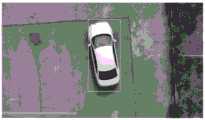
图4是无人机检测到视野中车辆的示意图;Fig. 4 is a schematic diagram of a vehicle in the field of view detected by the drone;
表1是本实施例目标检测模型在Visdrone数据集上的性能指标Table 1 is the performance index of the target detection model of this embodiment on the Visdrone data set
具体实施方式Detailed ways
下面结合实施例和附图对本发明的一种基于无人机视觉系统的地面目标地理坐标定位方做出详细说明。A method for locating the geographic coordinates of the ground target based on the UAV vision system of the present invention will be described in detail below in conjunction with the embodiments and the accompanying drawings.
本发明的一种基于无人机视觉系统的地面目标地理坐标定位方法,是在无人机视觉采集系统上实现的。首先进行软硬件平台的搭建,具体包括如下两部分:A ground target geographic coordinate positioning method based on the UAV vision system of the present invention is realized on the UAV vision acquisition system. First, build the hardware and software platform, which includes the following two parts:
1.搭建搜索和定位平台:1. Build a search and positioning platform:
实施例中所述的无人机视觉采集系统如图1所示,包括有安装在DJI M210 RTK(Real-time kinematic,实时动态)四旋翼无人机1上的禅思X5S广角云台相机2,安装在M210 RTK四旋翼无人机1上的处理器载板3,安装在RTSO-9003U处理器载板3上的NVIDIATegra x2处理器4,安装在M210RTK四旋翼无人机1上的RTK天线5,安装在M210 RTK四旋翼无人机1上与处理器载板3连接的长距离数据传输电台模块A6,安装在M210 RTK四旋翼无人机1上的长距离图像传输模块A7,设置于地面的RTK移动基站8,安装在地面端电脑9上的长距离数据传输模块B6、美乐威USB Capture Gen HDMI视频采集卡10,与HDMI视频采集卡相连的图像传输模块B7。The unmanned aerial vehicle vision collection system described in the embodiment is as shown in Figure 1, includes and is installed on DJI M210 RTK (Real-time kinematic, real-time dynamic) four-rotor UAV 1 Zenmuse X5S wide-angle pan-tilt camera 2 , the processor carrier board 3 installed on the M210 RTK quadrotor drone 1, the NVIDIA Tegra
平台主要分为无人机端与地面端两部分。云台相机可以通过机械防抖使无人机在飞行过程中采集的图像更加清晰稳定,云台相机上的广角镜头是为了使采集的图像具有更大的视野范围。RTK天线让无人机可以进行高精度的实时差分定位,便于无人机在目标搜索任务中对目标进行更精确的定位。The platform is mainly divided into two parts: the UAV end and the ground end. The gimbal camera can make the images collected by the UAV during the flight clearer and more stable through mechanical anti-shake. The wide-angle lens on the gimbal camera is to make the collected images have a larger field of view. The RTK antenna allows the UAV to perform high-precision real-time differential positioning, which facilitates the UAV to more accurately locate the target in the target search task.
无人机通过数据传输接收地面端发送的搜索任务和各种指令,云台相机实时采集图像通过M210RTK与Cendence遥控器之间的图像传输链路将图像传回地面端,然后通过美乐威Capture Gen HDMI图像采集卡将传回的信号采集到运行在地面端工作站,由地面端系统读取云台相机采集到的图像并使用目标检测模型进行目标检测。The UAV receives the search tasks and various instructions sent by the ground end through data transmission. The gimbal camera collects images in real time and sends the images back to the ground end through the image transmission link between the M210RTK and the Cendence remote control, and then through Magewell Capture The Gen HDMI image acquisition card collects the returned signal to the workstation running on the ground end, and the ground end system reads the images collected by the pan-tilt camera and uses the target detection model for target detection.
二、搭建目标检测系统:2. Build a target detection system:
(1)模型选择(1) Model selection
为了实现目标搜索功能,我们采用目标检测算法。针对无人机视角下的目标检测问题,考虑到无人机视角下的目标较小,在本实施例中选择了具有特征金字塔结构的YOLOv3模型作为目标检测算法。In order to realize the target search function, we adopt the target detection algorithm. Aiming at the target detection problem under the perspective of the drone, considering that the target under the perspective of the drone is small, in this embodiment, the YOLOv3 model with a feature pyramid structure is selected as the target detection algorithm.
YOLO系列单阶段目标检测模型由RPN网络发展而来,速度要比两阶段检测目标检测模型快很多,在目前常见的设备上可以满足实时性的要求。YOLOv3在YOLO的基础上增加了特征融合金字塔,将不同层的特征融合并在多个尺度的特征上进行预测,这使得YOLOv3对小目标的检测很有效。The YOLO series single-stage target detection model is developed from the RPN network, which is much faster than the two-stage target detection model, and can meet the real-time requirements on the current common equipment. YOLOv3 adds a feature fusion pyramid on the basis of YOLO, which fuses features of different layers and predicts features at multiple scales, which makes YOLOv3 very effective for small target detection.
(2)训练数据设置(2) Training data setting
无人机视角进行目标检测普遍存在一个问题,就是在俯视视角下采集的图片较正常采集的图片视野更大,目标小,目标位置随机,存在各种角度变换等。在普通视角数据集(比如COCO数据集等)上训练的模型,无法很好适应俯视视角下的目标检测。我们需要在无人机视角下的目标检测数据集上训练本实例模型,以实现俯视视角下的目标检测。There is a common problem in target detection from the drone's perspective, that is, the pictures collected under the top view perspective have a larger field of view than the normal pictures, the target is small, the target position is random, and there are various angle changes. Models trained on common view datasets (such as COCO datasets, etc.) cannot be well adapted to target detection in bird's-eye view. We need to train the example model on the target detection data set from the perspective of the drone to achieve target detection from the perspective of the bird.
Visdrone数据集是由天津大学机器学习和数据挖掘实验室AIskyeye团队制作的一个无人机视角下的数据集,以满足无人机上一些重要的视觉任务的研究。数据集由视频和静态图像组成,由各个型号的无人机搭载多种摄像设备进行收集得到,数据集包括了各个中国各个地理位置下的各种场景,具有行人、机动车辆和非机动车辆等目标。数据集中一共对260余万个目标进行了包围框与类别的标注,除去这些基本的标注信息,还对每个目标的被遮挡及被截断的情况进行了标注,方便更好的进行无人机视角下的视觉算法的开发。The Visdrone data set is a data set from the perspective of drones produced by the AIskyeye team of the Machine Learning and Data Mining Laboratory of Tianjin University to meet the research of some important visual tasks on drones. The data set consists of video and static images, which are collected by various types of drones equipped with various camera equipment. The data set includes various scenes in various geographical locations in China, including pedestrians, motor vehicles and non-motor vehicles, etc. Target. A total of more than 2.6 million objects in the data set are labeled with bounding boxes and categories. In addition to these basic labeling information, the occlusion and truncated conditions of each target are also marked, which is convenient for better drone detection. Development of vision algorithms in perspective.
(3)训练模型(3) Training model
选择了Python环境下的Pytorch深度学习框架进行YOLOv3的搭建与训练。为了提升YOLOv3对目标的召回率,有效利用各个尺度预测层的输出,对实施例中的目标检测算法YOLOv3训练时的监督策略进行了调整。在训练阶段读入标签后给每个目标编码时,在每个输出层上各找一个和该目标的包围框具有最大交并比的先验框,将损失函数中该先验框位置的指示函数置为1,然后设定一个拒绝阈值,若指示函数被置为1的先验框与目标的交并比小于该拒绝阈值,则将该指示函数置为0。最后将目标的信息赋给指数函数为1的先验框。这样当目标的尺寸与两个输出层上的先验框尺寸都很接近时,可以用两层输出同时预测该目标,有效利用不同尺度下的特征。The Pytorch deep learning framework in the Python environment was selected for the construction and training of YOLOv3. In order to improve the recall rate of YOLOv3 to the target and effectively use the output of each scale prediction layer, the supervision strategy during the training of the target detection algorithm YOLOv3 in the embodiment is adjusted. When encoding each target after reading the label in the training phase, find an a priori frame with the largest intersection and union ratio with the bounding box of the target on each output layer, and use the indication of the position of the a priori frame in the loss function The function is set to 1, and then a rejection threshold is set. If the intersection ratio between the a priori box whose indicator function is set to 1 and the target is smaller than the rejection threshold, the indicator function is set to 0. Finally, the information of the target is assigned to the prior box with an exponential function of 1. In this way, when the size of the target is very close to the size of the prior frame on the two output layers, the output of the two layers can be used to predict the target at the same time, and the features at different scales can be effectively used.
通过该监督方式在Visdrone数据集上进行了模型的训练,模型完成训练后的精度如表1所示。The model is trained on the Visdrone dataset through this supervision method, and the accuracy of the model after training is shown in Table 1.
(4)模型部署(4) Model deployment
用TensorRT推理引擎将训练好的模型部署到我们的地面端软件系统。TensorRT具有以下两个特性:一个是通过它的解析器可以将各个框架下的深度学习模型部署在我们的软件系统,第二个是它可以为模型的预测过程进行加速。首先将Pytorch编写的YOLOv3的模型转为ONNX格式的模型。然后基于ONNX的计算图用YOLOv3生成TensorRT的推理引擎并将引擎序列化保存到本地,检测程序直接将本地的YOLOv3推理引擎反序列化加载到程序中用于检测。Use the TensorRT inference engine to deploy the trained model to our ground-end software system. TensorRT has the following two characteristics: one is that it can deploy deep learning models under various frameworks in our software system through its parser, and the other is that it can accelerate the prediction process of the model. First, convert the YOLOv3 model written by Pytorch to the model in ONNX format. Then the calculation graph based on ONNX uses YOLOv3 to generate TensorRT's reasoning engine and serializes the engine and saves it locally. The detection program directly deserializes and loads the local YOLOv3 reasoning engine into the program for detection.
由TensorRT部署后的YOLOv3在检测速度上有较大提升,显存用量有大幅的下降,所以本实施例中采用这种部署方式。地面端将云台相机采集到的图像输入到该模型,经模型推理后可得到图片中每个预设目标的类别以及目标外接矩形框的位置。The detection speed of YOLOv3 deployed by TensorRT has been greatly improved, and the memory usage has been greatly reduced, so this deployment method is adopted in this embodiment. The ground terminal inputs the images collected by the PTZ camera into the model, and after model reasoning, the category of each preset target in the picture and the position of the bounding rectangle of the target can be obtained.
软硬件系统搭建完成后,开始执行目标搜索与定位任务。After the hardware and software system is built, the target search and positioning tasks are started.
将地面端电脑,RTK移动基站与无人机部署到预定位置。令云台相机以向下转动90°的姿态进行图像采集,即相机朝向地面且与地面垂直,简化了相机坐标系与机体坐标系换算的过程,减少了云台角度换算时所造成的误差。Deploy the ground computer, RTK mobile base station and drone to the predetermined location. The gimbal camera is rotated 90° downward for image acquisition, that is, the camera faces the ground and is perpendicular to the ground, which simplifies the conversion process between the camera coordinate system and the body coordinate system, and reduces the error caused by the gimbal angle conversion.
起飞前在地面站设置搜索区域进行无人机的航线规划,这个搜索区域信号是由搜索区域的一系列边界点组成。首先获取当前GPS坐标,计算目标搜索区域各边界点坐标的距离,选择最短距离的目标点,计算飞行角度,直线飞行到搜索区域的边界点,开始进行目标搜索和定位。为了保证能够检测到目标,固定一个高度,在与地面水平的平面内规划路径进行搜索,由于高度固定,搜索视野半径已知,使用本系统就可以根据区域生成往复式航线。在地面端电脑划定待搜索区域并设置待搜索目标,根据待搜索区域自动进行航线规划,生成航线覆盖搜索区域,所生成的航线如图2所示,为等间隔且互相平行的。Before take-off, set up a search area on the ground station for UAV route planning. The search area signal is composed of a series of boundary points in the search area. First obtain the current GPS coordinates, calculate the distance between the coordinates of each boundary point in the target search area, select the target point with the shortest distance, calculate the flight angle, fly straight to the boundary point of the search area, and start target search and positioning. In order to ensure that the target can be detected, a height is fixed, and the search path is planned in a plane horizontal to the ground. Since the height is fixed and the radius of the search field of view is known, the system can generate a reciprocating route according to the area. The computer on the ground side defines the area to be searched and sets the target to be searched, automatically plans the route according to the area to be searched, and generates a route covering the search area. The generated routes are equally spaced and parallel to each other, as shown in Figure 2.
航线规划完毕并设置好待搜索目标后,由地面站发送起飞指令。无人机起飞后沿生成的往复式航线飞行,过程中始终开启着图像传输和地面端的目标检测功能。一旦地面端检测到视野中存在目标,如图4所示,地面端立即将检测到目标的信号以及目标位置通过通信模块反馈给无人机。无人机接收到目标位置之后将在当前航线上与目标点之间作临时路径变更,无人机飞到目标据航线的最小距离位置点,开始向目标位置飞行。目标中心位置与图像中心位置的偏差通过数据传输电台发送给无人机,无人机系统中的控制算法通过该偏差控制无人机向目标方向定高飞行。当目标中心与图像中心的偏差小于预设阈值时,则认为无人机悬停在目标正上方,记录此目标的ID,并将无人机自身的地理坐标作为目标的地理坐标记录下来,发送到地面端。待定位完成或超时后无人机返回原规划航线,继续进行搜索。如果视野中同时出现多个目标时,按如图3所示的策略依次进行定位。由于无人机使用了RTK定位系统获取地理坐标,所以该定位方法的相对误差可到0.1m以下。After the route planning is completed and the target to be searched is set, the ground station will send a take-off command. After taking off, the UAV flies along the generated reciprocating route, and the image transmission and ground-side target detection functions are always turned on during the process. Once the ground terminal detects that there is a target in the field of view, as shown in Figure 4, the ground terminal immediately feeds back the signal of the detected target and the target position to the UAV through the communication module. After the UAV receives the target position, it will make a temporary route change between the current route and the target point, and the UAV will fly to the minimum distance point according to the target route and start flying to the target position. The deviation between the center position of the target and the center position of the image is sent to the UAV through the data transmission station, and the control algorithm in the UAV system uses this deviation to control the UAV to fly to the target direction at a fixed height. When the deviation between the center of the target and the center of the image is less than the preset threshold, it is considered that the drone is hovering directly above the target, the ID of the target is recorded, and the geographic coordinates of the drone itself are recorded as the geographic coordinates of the target, and sent to the ground side. After the positioning is completed or the timeout expires, the UAV returns to the original planned route and continues to search. If multiple targets appear in the field of view at the same time, locate them sequentially according to the strategy shown in Figure 3. Since the UAV uses the RTK positioning system to obtain geographic coordinates, the relative error of this positioning method can be below 0.1m.
当预定区域搜索完毕后或无人机电量不足时,无人机根据当前GPS坐标和起飞位置的GPS坐标,计算最短路径,返航回到起飞地点,完成本次搜素定位任务。When the predetermined area is searched or the battery of the UAV is low, the UAV calculates the shortest path based on the current GPS coordinates and the GPS coordinates of the take-off location, returns to the take-off location, and completes the search and positioning task.
表1本实施例目标检测模型在Visdrone数据集上的性能指标Table 1 Performance indicators of the target detection model of this embodiment on the Visdrone dataset

上superior
上面结合附图对本发明的实施方式做了详细说明,但是本发明并不限于上述实施方式,任何熟悉本技术领域的研究人员在本发明专利所公开的范围内,在不脱离本发明宗旨的前提下做出的各种变化均属于本发明专利的保护范围。The embodiments of the present invention have been described in detail above in conjunction with the accompanying drawings, but the present invention is not limited to the above-mentioned embodiments. Any researcher familiar with the technical field is within the scope disclosed by the patent of the present invention, without departing from the gist of the present invention. The various changes made below all belong to the protection scope of the patent of the present invention.
Claims (2)
Priority Applications (1)
| Application Number | Priority Date | Filing Date | Title |
|---|---|---|---|
| CN201911245318.5ACN111178148B (en) | 2019-12-06 | 2019-12-06 | A ground target geographic coordinate positioning method based on UAV vision system |
Applications Claiming Priority (1)
| Application Number | Priority Date | Filing Date | Title |
|---|---|---|---|
| CN201911245318.5ACN111178148B (en) | 2019-12-06 | 2019-12-06 | A ground target geographic coordinate positioning method based on UAV vision system |
Publications (2)
| Publication Number | Publication Date |
|---|---|
| CN111178148A CN111178148A (en) | 2020-05-19 |
| CN111178148Btrue CN111178148B (en) | 2023-06-02 |
Family
ID=70657279
Family Applications (1)
| Application Number | Title | Priority Date | Filing Date |
|---|---|---|---|
| CN201911245318.5AExpired - Fee RelatedCN111178148B (en) | 2019-12-06 | 2019-12-06 | A ground target geographic coordinate positioning method based on UAV vision system |
Country Status (1)
| Country | Link |
|---|---|
| CN (1) | CN111178148B (en) |
Families Citing this family (11)
| Publication number | Priority date | Publication date | Assignee | Title |
|---|---|---|---|---|
| CN111879313B (en)* | 2020-07-31 | 2022-08-12 | 中国人民解放军国防科技大学 | A multi-target continuous positioning method and system based on UAV image recognition |
| CN112232132A (en)* | 2020-09-18 | 2021-01-15 | 北京理工大学 | A Target Recognition and Positioning Method Based on Navigation Information |
| CN112577481B (en)* | 2020-12-22 | 2022-07-26 | 西北工业大学 | Ground target positioning method for rotor unmanned aerial vehicle |
| CN114115359B (en)* | 2021-10-26 | 2024-06-14 | 南京邮电大学 | Unmanned aerial vehicle mountain area sheep searching system and working method thereof |
| CN114189872B (en)* | 2021-12-08 | 2022-11-29 | 香港中文大学(深圳) | Method and device for determining relay service position of unmanned aerial vehicle |
| CN115019216B (en)* | 2022-08-09 | 2022-10-21 | 江西师范大学 | Real-time ground object detection and positioning counting method, system and computer |
| CN116824414B (en)* | 2023-08-29 | 2023-11-14 | 深圳市硕腾科技有限公司 | Method for rapidly deploying RTK (real time kinematic) by unmanned aerial vehicle |
| CN117110214A (en)* | 2023-09-01 | 2023-11-24 | 河北华厚天成环保技术有限公司 | Water quality analysis system and method based on hyperspectral imaging of unmanned aerial vehicle |
| CN117611668B (en)* | 2023-11-27 | 2024-09-03 | 河海大学 | A method for UAV target visual localization based on multi-source priors |
| CN118018104B (en)* | 2024-04-09 | 2024-07-05 | 中科元境(江苏)文化科技有限公司 | Unmanned aerial vehicle-based data transmission method and system |
| CN119992925B (en)* | 2025-04-10 | 2025-07-25 | 江西联创精密机电有限公司 | Unmanned reconnaissance aircraft simulation training method and system |
Citations (10)
| Publication number | Priority date | Publication date | Assignee | Title |
|---|---|---|---|---|
| CN103868521A (en)* | 2014-02-20 | 2014-06-18 | 天津大学 | Autonomous quadrotor unmanned aerial vehicle positioning and controlling method based on laser radar |
| CN107422743A (en)* | 2015-09-12 | 2017-12-01 | 深圳九星智能航空科技有限公司 | The unmanned plane alignment system of view-based access control model |
| CN107589758A (en)* | 2017-08-30 | 2018-01-16 | 武汉大学 | A kind of intelligent field unmanned plane rescue method and system based on double source video analysis |
| CN107729808A (en)* | 2017-09-08 | 2018-02-23 | 国网山东省电力公司电力科学研究院 | A kind of image intelligent acquisition system and method for power transmission line unmanned machine inspection |
| CN107817820A (en)* | 2017-10-16 | 2018-03-20 | 复旦大学 | A kind of unmanned plane autonomous flight control method and system based on deep learning |
| CN107911429A (en)* | 2017-11-04 | 2018-04-13 | 南京奇蛙智能科技有限公司 | A kind of online traffic flow monitoring method in unmanned plane high in the clouds based on video |
| CN109917818A (en)* | 2019-01-31 | 2019-06-21 | 天津大学 | Collaborative search and containment method based on ground robot |
| WO2019144575A1 (en)* | 2018-01-24 | 2019-08-01 | 中山大学 | Fast pedestrian detection method and device |
| CN110081982A (en)* | 2019-03-11 | 2019-08-02 | 中林信达(北京)科技信息有限责任公司 | A kind of unmanned plane target localization method based on double spectrum photoelectric search |
| WO2019192397A1 (en)* | 2018-04-04 | 2019-10-10 | 华中科技大学 | End-to-end recognition method for scene text in any shape |
- 2019
- 2019-12-06CNCN201911245318.5Apatent/CN111178148B/ennot_activeExpired - Fee Related
Patent Citations (10)
| Publication number | Priority date | Publication date | Assignee | Title |
|---|---|---|---|---|
| CN103868521A (en)* | 2014-02-20 | 2014-06-18 | 天津大学 | Autonomous quadrotor unmanned aerial vehicle positioning and controlling method based on laser radar |
| CN107422743A (en)* | 2015-09-12 | 2017-12-01 | 深圳九星智能航空科技有限公司 | The unmanned plane alignment system of view-based access control model |
| CN107589758A (en)* | 2017-08-30 | 2018-01-16 | 武汉大学 | A kind of intelligent field unmanned plane rescue method and system based on double source video analysis |
| CN107729808A (en)* | 2017-09-08 | 2018-02-23 | 国网山东省电力公司电力科学研究院 | A kind of image intelligent acquisition system and method for power transmission line unmanned machine inspection |
| CN107817820A (en)* | 2017-10-16 | 2018-03-20 | 复旦大学 | A kind of unmanned plane autonomous flight control method and system based on deep learning |
| CN107911429A (en)* | 2017-11-04 | 2018-04-13 | 南京奇蛙智能科技有限公司 | A kind of online traffic flow monitoring method in unmanned plane high in the clouds based on video |
| WO2019144575A1 (en)* | 2018-01-24 | 2019-08-01 | 中山大学 | Fast pedestrian detection method and device |
| WO2019192397A1 (en)* | 2018-04-04 | 2019-10-10 | 华中科技大学 | End-to-end recognition method for scene text in any shape |
| CN109917818A (en)* | 2019-01-31 | 2019-06-21 | 天津大学 | Collaborative search and containment method based on ground robot |
| CN110081982A (en)* | 2019-03-11 | 2019-08-02 | 中林信达(北京)科技信息有限责任公司 | A kind of unmanned plane target localization method based on double spectrum photoelectric search |
Non-Patent Citations (1)
| Title |
|---|
| 张军 ; 杨伯轩 ; 杨正瓴 ; .基于行人与车辆关系模型的行人检测.计算机应用与软件.2016,(第08期),全文.* |
Also Published As
| Publication number | Publication date |
|---|---|
| CN111178148A (en) | 2020-05-19 |
Similar Documents
| Publication | Publication Date | Title |
|---|---|---|
| CN111178148B (en) | A ground target geographic coordinate positioning method based on UAV vision system | |
| Luo et al. | A survey of intelligent transmission line inspection based on unmanned aerial vehicle | |
| US11584525B2 (en) | Deep learning-based localization of UAVs with respect to nearby pipes | |
| Xing et al. | Multi-UAV cooperative system for search and rescue based on YOLOv5 | |
| CN114373138A (en) | Full-automatic unmanned aerial vehicle inspection method and system for high-speed railway | |
| CN108109437B (en) | Unmanned aerial vehicle autonomous route extraction and generation method based on map features | |
| JP2022520019A (en) | Image processing methods, equipment, mobile platforms, programs | |
| CN113485441A (en) | Distribution network inspection method combining unmanned aerial vehicle high-precision positioning and visual tracking technology | |
| CN113359810A (en) | Unmanned aerial vehicle landing area identification method based on multiple sensors | |
| CN111679695B (en) | Unmanned aerial vehicle cruising and tracking system and method based on deep learning technology | |
| CN112904877A (en) | Automatic fan blade inspection system and method based on unmanned aerial vehicle | |
| KR102289752B1 (en) | A drone for performring route flight in gps blocked area and methed therefor | |
| KR102557775B1 (en) | Drone used 3d mapping method | |
| CN113674355A (en) | Target identification and positioning method based on camera and laser radar | |
| KR20230026916A (en) | 3d mapping method with time series information using drone | |
| CN110104167A (en) | A kind of automation search and rescue UAV system and control method using infrared thermal imaging sensor | |
| CN120359431A (en) | System and method for active light-based accurate positioning of aircraft in GPS rejection environments | |
| CN110823223A (en) | Path planning method and device for unmanned aerial vehicle cluster | |
| CN117873158A (en) | Unmanned aerial vehicle routing inspection complex route optimization method based on live-action three-dimensional model | |
| CN116912719B (en) | A method for searching injured persons based on drone rescue that can overcome partial occlusion conditions | |
| CN106052695A (en) | Flight inspection tour system and method performing navigation by utilizing 360-degree laser scanner | |
| CN118857278A (en) | A method and system for surveying and mapping geographic information | |
| CN119889050A (en) | Method for identifying vehicles in service area based on three-dimensional laser radar data | |
| CN114564049B (en) | Unmanned aerial vehicle wide area search device and method based on deep learning | |
| CN115686073A (en) | Unmanned aerial vehicle-based power transmission line inspection control method and system |
Legal Events
| Date | Code | Title | Description |
|---|---|---|---|
| PB01 | Publication | ||
| PB01 | Publication | ||
| SE01 | Entry into force of request for substantive examination | ||
| SE01 | Entry into force of request for substantive examination | ||
| GR01 | Patent grant | ||
| GR01 | Patent grant | ||
| CF01 | Termination of patent right due to non-payment of annual fee | ||
| CF01 | Termination of patent right due to non-payment of annual fee | Granted publication date:20230602 |