CN111166456A - Bone fracture plate - Google Patents
Bone fracture plateDownload PDFInfo
- Publication number
- CN111166456A CN111166456ACN202010172154.4ACN202010172154ACN111166456ACN 111166456 ACN111166456 ACN 111166456ACN 202010172154 ACN202010172154 ACN 202010172154ACN 111166456 ACN111166456 ACN 111166456A
- Authority
- CN
- China
- Prior art keywords
- bone
- shaft portion
- bone plate
- head
- holes
- Prior art date
- Legal status (The legal status is an assumption and is not a legal conclusion. Google has not performed a legal analysis and makes no representation as to the accuracy of the status listed.)
- Granted
Links
- 208000010392Bone FracturesDiseases0.000title1
- 210000000988bone and boneAnatomy0.000claimsabstractdescription139
- 210000002303tibiaAnatomy0.000claimsdescription17
- 241001227561ValgusSpecies0.000claimsdescription7
- 210000000689upper legAnatomy0.000claimsdescription6
- 230000007423decreaseEffects0.000claimsdescription3
- 230000035876healingEffects0.000abstractdescription4
- 230000006641stabilisationEffects0.000abstractdescription2
- 238000011105stabilizationMethods0.000abstractdescription2
- 238000001356surgical procedureMethods0.000description8
- 230000006835compressionEffects0.000description4
- 238000007906compressionMethods0.000description4
- 238000010586diagramMethods0.000description4
- 239000000463materialSubstances0.000description4
- 208000003947Knee OsteoarthritisDiseases0.000description3
- 238000000034methodMethods0.000description3
- 201000008482osteoarthritisDiseases0.000description3
- 208000006735PeriostitisDiseases0.000description2
- 230000007547defectEffects0.000description2
- 201000010099diseaseDiseases0.000description2
- 208000037265diseases, disorders, signs and symptomsDiseases0.000description2
- 210000002414legAnatomy0.000description2
- 210000003141lower extremityAnatomy0.000description2
- 210000003460periosteumAnatomy0.000description2
- 230000002980postoperative effectEffects0.000description2
- 230000006978adaptationEffects0.000description1
- 230000009286beneficial effectEffects0.000description1
- 239000012620biological materialSubstances0.000description1
- 238000004891communicationMethods0.000description1
- 238000007796conventional methodMethods0.000description1
- 238000012937correctionMethods0.000description1
- 230000006735deficitEffects0.000description1
- 238000013461designMethods0.000description1
- 239000003814drugSubstances0.000description1
- 230000000694effectsEffects0.000description1
- 239000000945fillerSubstances0.000description1
- 230000006870functionEffects0.000description1
- 238000009434installationMethods0.000description1
- 230000010354integrationEffects0.000description1
- 230000003993interactionEffects0.000description1
- 230000002427irreversible effectEffects0.000description1
- 230000008407joint functionEffects0.000description1
- 210000003127kneeAnatomy0.000description1
- 230000003902lesionEffects0.000description1
- 230000000399orthopedic effectEffects0.000description1
- 239000011148porous materialSubstances0.000description1
- 230000000472traumatic effectEffects0.000description1
Images


Classifications
- A—HUMAN NECESSITIES
- A61—MEDICAL OR VETERINARY SCIENCE; HYGIENE
- A61B—DIAGNOSIS; SURGERY; IDENTIFICATION
- A61B17/00—Surgical instruments, devices or methods
- A61B17/56—Surgical instruments or methods for treatment of bones or joints; Devices specially adapted therefor
- A61B17/58—Surgical instruments or methods for treatment of bones or joints; Devices specially adapted therefor for osteosynthesis, e.g. bone plates, screws or setting implements
- A61B17/68—Internal fixation devices, including fasteners and spinal fixators, even if a part thereof projects from the skin
- A61B17/80—Cortical plates, i.e. bone plates; Instruments for holding or positioning cortical plates, or for compressing bones attached to cortical plates
- A61B17/8004—Cortical plates, i.e. bone plates; Instruments for holding or positioning cortical plates, or for compressing bones attached to cortical plates with means for distracting or compressing the bone or bones
- A61B17/8014—Cortical plates, i.e. bone plates; Instruments for holding or positioning cortical plates, or for compressing bones attached to cortical plates with means for distracting or compressing the bone or bones the extension or compression force being caused by interaction of the plate hole and the screws
- A—HUMAN NECESSITIES
- A61—MEDICAL OR VETERINARY SCIENCE; HYGIENE
- A61B—DIAGNOSIS; SURGERY; IDENTIFICATION
- A61B17/00—Surgical instruments, devices or methods
- A61B17/56—Surgical instruments or methods for treatment of bones or joints; Devices specially adapted therefor
- A61B17/58—Surgical instruments or methods for treatment of bones or joints; Devices specially adapted therefor for osteosynthesis, e.g. bone plates, screws or setting implements
- A61B17/68—Internal fixation devices, including fasteners and spinal fixators, even if a part thereof projects from the skin
- A61B17/80—Cortical plates, i.e. bone plates; Instruments for holding or positioning cortical plates, or for compressing bones attached to cortical plates
- A61B17/8061—Cortical plates, i.e. bone plates; Instruments for holding or positioning cortical plates, or for compressing bones attached to cortical plates specially adapted for particular bones
Landscapes
- Health & Medical Sciences (AREA)
- Orthopedic Medicine & Surgery (AREA)
- Surgery (AREA)
- Life Sciences & Earth Sciences (AREA)
- Heart & Thoracic Surgery (AREA)
- Nuclear Medicine, Radiotherapy & Molecular Imaging (AREA)
- Engineering & Computer Science (AREA)
- Biomedical Technology (AREA)
- Neurology (AREA)
- Medical Informatics (AREA)
- Molecular Biology (AREA)
- Animal Behavior & Ethology (AREA)
- General Health & Medical Sciences (AREA)
- Public Health (AREA)
- Veterinary Medicine (AREA)
- Surgical Instruments (AREA)
Abstract
Translated fromChinese
Description
Translated fromChinese技术领域technical field
本发明实施例涉及骨科医疗器械技术领域,尤其涉及一种用于骨骼各部相对位置固定的接骨板。Embodiments of the present invention relate to the technical field of orthopedic medical devices, and in particular, to a bone plate for fixing relative positions of various parts of a bone.
背景技术Background technique
膝关节骨性关节炎,是最常见的膝关节疾病,表现为腿部弯曲变形(O形腿)、疼痛以及活动障碍等。尽管此病不具致命性,但却严重影响了病人的正常生活,使病人生活质量明显下降。Knee osteoarthritis, the most common knee disease, is characterized by flexion of the leg (O-shaped leg), pain, and mobility impairment. Although the disease is not fatal, it seriously affects the normal life of the patient and significantly reduces the quality of life of the patient.
膝关节骨性关节炎的治疗,以前都是采取关节置换手术为主要解决办法,但是关节置换以后存在部分功能丢失的问题,同时,由于关节置换属于不可逆手术,对患者创伤较大。近年来,随着医学的不断进步与内固定材料的不断更新,对膝关节骨性关节炎的治疗提出阶梯化治疗方法。当出现生理性病变后,首先采取保膝手术治疗,避免直接进行人工关节置换,保膝手术临床称为“胫骨高位截骨术”,该手术又分为外侧闭合与内侧开放的截骨术。目前,比较广泛应用的为内侧的开放截骨,在胫骨平台下内侧打开一个楔形切口,通过调整切口撑开的角度,来调整下肢力线,使下肢力线恢复,最后使用接骨板固定,达到消除病痛,恢复关节的功能。In the past, joint replacement surgery was the main solution for the treatment of knee osteoarthritis. However, there is a problem of partial function loss after joint replacement. At the same time, because joint replacement is an irreversible operation, it is more traumatic to patients. In recent years, with the continuous progress of medicine and the continuous updating of internal fixation materials, a stepped treatment method has been proposed for the treatment of knee osteoarthritis. When physiological lesions occur, knee-sparing surgery is first used to avoid direct artificial joint replacement. Knee-sparing surgery is clinically called "high tibial osteotomy", which is further divided into lateral closed and medial open osteotomy. At present, the more widely used medial open osteotomy is to open a wedge-shaped incision on the lower and inner side of the tibial plateau. By adjusting the opening angle of the incision, the alignment of the lower extremity can be adjusted to restore the alignment of the lower extremity. Finally, a bone plate is used for fixation to achieve Eliminate pain and restore joint function.
相关技术中,可用于胫骨高位截骨术的接骨板通常为单根脚或两根脚,如两根脚形状的T形、U形、L形接骨板。关于上述技术方案,发明人发现至少存在如下一些技术问题:例如,T形板术后固定摆放的位置很难把握,且不具备抗旋性,直接影响手术效果;U形板固定,只能简单的固定切口撑开的距离,并不能提供坚强固定,需要患者长时间卧床;L形板同样只能提供相对的固定,也在抗旋转等方面存在缺陷。因此,有必要改善上述相关技术方案中存在的一个或者多个问题。In the related art, a bone plate that can be used for high tibial osteotomy is usually a single foot or two feet, such as a T-shaped, U-shaped, and L-shaped bone plate in the shape of two feet. Regarding the above technical solutions, the inventor found that there are at least the following technical problems: for example, it is difficult to grasp the fixed position of the T-shaped plate after surgery, and it does not have anti-rotation properties, which directly affects the surgical effect; the U-shaped plate is fixed, only Simply fixing the distance of the incision can not provide strong fixation and requires the patient to stay in bed for a long time; the L-shaped plate can only provide relative fixation, and it also has defects in anti-rotation and other aspects. Therefore, it is necessary to improve one or more problems existing in the above-mentioned related technical solutions.
需要注意的是,本部分旨在为权利要求书中陈述的本发明的技术方案提供背景或上下文。此处的描述不因为包括在本部分中就承认是现有技术。It should be noted that this section is intended to provide a background or context for the technical solutions of the invention recited in the claims. The descriptions herein are not admitted to be prior art by inclusion in this section.
发明内容SUMMARY OF THE INVENTION
本发明实施例的目的在于提供一种接骨板,进而至少在一定程度上克服由于相关技术的限制和缺陷而导致的一个或者多个问题。The purpose of the embodiments of the present invention is to provide a bone plate, thereby at least to a certain extent overcoming one or more problems caused by the limitations and defects of the related art.
本发明实施例提供的一种接骨板,用于骨骼各部相对位置的固定,包括:A bone plate provided by the embodiment of the present invention is used for fixing the relative position of each part of the bone, including:
头部,所述头部呈板状,用于沿骨骼长度方向固定于骨骼切口的一侧;The head, which is in the shape of a plate, is used to be fixed to one side of the bone incision along the length of the bone;
轴部,用于沿所述骨骼长度方向固定于所述骨骼切口的另一侧,所述轴部整体呈P形板状,包括在侧向相互连接的第一轴部和第二轴部,所述第一轴部的长度大于所述第二轴部的长度,且所述第一轴部和所述第二轴部之间具有一沿长度方向延伸的空隙;A shaft portion is used to be fixed on the other side of the bone incision along the length direction of the bone, the shaft portion is in the shape of a P-shaped plate as a whole, and includes a first shaft portion and a second shaft portion that are connected to each other in the lateral direction, The length of the first shaft portion is greater than the length of the second shaft portion, and there is a gap extending along the length direction between the first shaft portion and the second shaft portion;
连接部,连接所述头部和轴部;a connecting portion, connecting the head portion and the shaft portion;
其中,所述头部向背离所述骨骼的方向外翻,且具有一预设的外翻角度。Wherein, the head is everted in a direction away from the bone, and has a preset eversion angle.
本发明的一实施例中,所述预设的外翻角度为5°-11°。In an embodiment of the present invention, the preset eversion angle is 5°-11°.
本发明的一实施例中,所述连接部贴近所述骨骼的外表面上具有至少一个卡榫,用于嵌入所述骨骼切口中。In an embodiment of the present invention, at least one tenon is provided on the outer surface of the connecting portion close to the bone for being embedded in the bone incision.
本发明的一实施例中,所述卡榫整体呈楔形,且所述卡榫的底面与所述连接部接合,所述底面靠近所述轴部的边与水平线的夹角为10°-35°。In an embodiment of the present invention, the tenon is wedge-shaped as a whole, and the bottom surface of the tenon is engaged with the connecting portion, and the angle between the side of the bottom surface close to the shaft portion and the horizontal line is 10°-35° °.
本发明的一实施例中,所述空隙自所述轴部延伸至所述连接部或所述头部,且所述空隙的宽度为0.5mm-3mm。In an embodiment of the present invention, the gap extends from the shaft portion to the connecting portion or the head portion, and the width of the gap is 0.5mm-3mm.
本发明的一实施例中,所述接骨板的厚度从连接部开始分别向所述头部和所述轴部递减。In an embodiment of the present invention, the thickness of the bone plate decreases from the connecting portion to the head portion and the shaft portion, respectively.
本发明的一实施例中,所述头部具有多个第一通孔,多个所述第一通孔间隔分布。In an embodiment of the present invention, the head has a plurality of first through holes, and the plurality of first through holes are distributed at intervals.
本发明的一实施例中,多个所述第一通孔排列成相对平行的两行或多行。In an embodiment of the present invention, a plurality of the first through holes are arranged in two or more relatively parallel rows.
本发明的一实施例中,所述第一轴部具有多个第二通孔,多个所述第二通孔间隔分布;以及In an embodiment of the present invention, the first shaft portion has a plurality of second through holes, and the plurality of second through holes are distributed at intervals; and
所述第二轴部具有多个第三通孔,多个所述第三通孔间隔分布。The second shaft portion has a plurality of third through holes, and the plurality of third through holes are distributed at intervals.
本发明的一实施例中,多个所述第二通孔形成的列和多个所述第三通孔形成的列相对平行。In an embodiment of the present invention, the rows formed by the plurality of second through holes and the rows formed by the plurality of third through holes are relatively parallel.
本发明的一实施例中,所述头部、轴部以及连接部中的任意一个或多个,在贴近所述骨骼的外表面上具有多个凸起部。In an embodiment of the present invention, any one or more of the head portion, the shaft portion and the connecting portion has a plurality of raised portions on the outer surface close to the bone.
本发明的一实施例中,多个所述凸起部之间均匀分布。In an embodiment of the present invention, the plurality of protruding portions are evenly distributed.
本发明的一实施例中,所述骨骼包括胫骨和股骨。In one embodiment of the present invention, the bones include tibia and femur.
本发明的实施例提供的技术方案可以包括以下有益效果:The technical solutions provided by the embodiments of the present invention may include the following beneficial effects:
本发明的实施例中,一方面,上述接骨板整体呈现P型结构,且头部朝向背离骨骼的方向外翻了一定的角度,可使接骨板完全贴合于胫骨表面,结合该接骨板头部以及轴部在骨骼上的分布位置,具备了抗扭、抗旋的性能,且术后可实现立即稳固,进一步增加了骨板固定的坚强性,减少了接骨板的使用数量。另一方面,设置于第一轴部和第二轴部之间的空隙,不仅提供了抗旋扭力,还减轻了对骨骼的压迫,可大大缩短骨骼愈合的时间。In the embodiments of the present invention, on the one hand, the above-mentioned bone plate has a P-shaped structure as a whole, and the head is everted at a certain angle in the direction away from the bone, so that the bone plate can be completely attached to the surface of the tibia, and the head of the bone plate can be completely attached to the surface of the tibia. The distribution position of the part and the shaft part on the bone has the properties of anti-torsion and anti-rotation, and can be stabilized immediately after the operation, which further increases the rigidity of the bone plate fixation and reduces the number of bone plates used. On the other hand, the gap provided between the first shaft portion and the second shaft portion not only provides anti-rotation torque, but also reduces the compression on the bone, which can greatly shorten the time for bone healing.
附图说明Description of drawings
此处的附图被并入说明书中并构成本说明书的一部分,示出了符合本发明的实施例,并与说明书一起用于解释本发明的原理。显而易见的,下面描述中的附图仅仅是本发明的一些实施例,对于本领域普通技术人员来讲,在不付出创造性劳动的前提下,还可以根据这些附图获得其他的附图。The accompanying drawings, which are incorporated in and constitute a part of this specification, illustrate embodiments consistent with the invention and together with the description serve to explain the principles of the invention. Obviously, the drawings in the following description are only some embodiments of the present invention, and for those of ordinary skill in the art, other drawings can also be obtained from these drawings without creative effort.
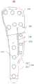
图1示出本发明示例性实施例中无卡榫的接骨板正视结构示意图;Fig. 1 shows a schematic front view of a bone plate without a tenon in an exemplary embodiment of the present invention;
图2示出本发明示例性实施例中有卡榫的接骨板结构示意图;FIG. 2 shows a schematic structural diagram of a bone plate with tenons in an exemplary embodiment of the present invention;
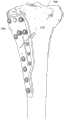
图3示出本发明示例性实施例中有卡榫的接骨板后视结构示意图;Fig. 3 is a schematic diagram showing the structure of the rear view of the bone plate with the tenon according to the exemplary embodiment of the present invention;
图4示出本发明示例性实施例中无卡榫的接骨板侧面结构示意图;Fig. 4 shows a schematic view of the side structure of a bone plate without a tenon in an exemplary embodiment of the present invention;
图5示出本发明示例性实施例中有卡榫的接骨板侧面结构示意图;Fig. 5 shows a schematic view of the side structure of the bone plate with tenon in an exemplary embodiment of the present invention;
图6示出本发明示例性实施例中无卡榫的接骨板后视结构示意图;Fig. 6 is a schematic diagram showing the structure of the back view of the bone plate without tenon in an exemplary embodiment of the present invention;
图7示出本发明示例性实施例中接骨板固定在胫骨上的示意图。FIG. 7 shows a schematic diagram of the fixation of the bone plate on the tibia in the exemplary embodiment of the present invention.
具体实施方式Detailed ways
现在将参考附图更全面地描述示例实施方式。然而,示例实施方式能够以多种形式实施,且不应被理解为限于在此阐述的范例;相反,提供这些实施方式使得本发明将更加全面和完整,并将示例实施方式的构思全面地传达给本领域的技术人员。所描述的特征、结构或特性可以以任何合适的方式结合在一个或更多实施方式中。Example embodiments will now be described more fully with reference to the accompanying drawings. Example embodiments, however, can be embodied in various forms and should not be construed as limited to the examples set forth herein; rather, these embodiments are provided so that this disclosure will be thorough and complete, and will fully convey the concept of example embodiments to those skilled in the art. The described features, structures, or characteristics may be combined in any suitable manner in one or more embodiments.
此外,附图仅为本发明实施例的示意性图解,并非一定是按比例绘制。图中相同的附图标记表示相同或类似的部分,因而将省略对它们的重复描述。Furthermore, the drawings are merely schematic illustrations of embodiments of the invention and are not necessarily drawn to scale. The same reference numerals in the drawings denote the same or similar parts, and thus their repeated descriptions will be omitted.
本示例实施方式中提供了一种接骨板100,用于骨骼各部相对位置的固定,参考图1至图6中所示,该接骨板100可以包括:一头部110、一轴部120以及一连接部130。头部110呈板状,可沿骨骼长度方向固定于骨骼切口的一侧,且头部110向背离骨骼的方向外翻了一定的角度。而轴部120可沿骨骼长度方向固定于骨骼的另一侧,轴部120整体呈P形板状,包括在侧向相互连接的第一轴部121和第二轴部122,第一轴部121的长度大于第二轴部122的长度,且第一轴部121和第二轴部122之间具有一沿长度方向延伸的空隙140。连接部130则用于连接头部110和轴部120。This exemplary embodiment provides a
本示例中,一方面,上述接骨板100整体呈现P型结构,且头部110向背离骨骼的方向外翻了一定的角度,如此,可使接骨板100更加符合胫骨的形状,能够完全贴合于胫骨的表面,再结合该接骨板100头部110以及轴部120在骨骼上的分布位置,使得该接骨板100具备了抗扭、抗旋的性能,在术后可实现立即稳固,并进一步增加了接骨板固定的坚强性,也减少了接骨板的使用数量。另一方面,设置于第一轴部121和第二轴部120之间的空隙140,不仅提供了抗旋扭力,且减轻了接骨板对骨骼的压迫,可大大缩短骨骼愈合的时间。In this example, on the one hand, the above-mentioned
在具体的示例中,上述骨骼可以包括胫骨和股骨。例如,如图7所示,当该接骨板100用于固定胫骨200近端各部相对位置时,将该接骨板100的头部110固定于胫骨切口210的上方,将接骨板100的轴部120固定于胫骨切口210的下方,且使得连接部130与胫骨切口210的位置相对应。当该接骨板100用于股骨远端各部相对位置的固定时,可将该接骨板100的头部110固定于股骨切口的下方,将接骨板100的轴部120固定于股骨切口的上方。In a specific example, the aforementioned bones may include the tibia and the femur. For example, as shown in FIG. 7 , when the
下面,将参考图1至图6对本示例实施方式中的上述接骨板100的各个部分进行更详细的说明。Hereinafter, various parts of the above-described
在一个实施例中,接骨板100的头部110、轴部120以及连接部130可由单一材料一体加工成型,具体的,加工材料可由生物相容性材料构成,例如钛、钛合金、不锈钢、可再吸收性生物材料以及同种异体移植物等等,然而并不限于此。In one embodiment, the
在一个实施例中,头部110预设的外翻角度为5°-11°,该外翻角度具体为头部110外表面的切线与连接部130表面的延长线之间的夹角。在胫骨高位截骨术中,医疗人员会在胫骨200上端约离关节面五公分处,截去一小块骨头以形成一切口210,并于其中填充一填充物用以向其上方扩张以迫使胫骨向外翻,以使胫骨的力学轴回到正常的位置。因此,头部110外翻5°-11°可以使得整个接骨板100与外翻的胫骨更加贴合,进而在固定时可以更加牢靠。同理,该外翻角度也适用于股骨远端校正手术的固定。In one embodiment, the preset valgus angle of the
示例性的,连接部130贴近骨骼的外表面具有至少一个卡榫131,用于嵌入骨骼的切口中。卡榫131为截骨面提供了牢固的支撑,可有效避免了胫骨高位截骨术后角度丢失或平台塌陷的问题。Exemplarily, the connecting
具体的,如图2中所示,卡榫131的数量为3个,当然在其他实施例中,卡榫131的数量还可以是1个、2个或者更多个,当然,随着卡榫131数量的变化,其体积也会相应改变。Specifically, as shown in FIG. 2 , the number of
在一个实施例中,卡榫131整体呈楔形,且卡榫131的底面(图未示)与连接部130接合。卡榫131整体呈楔形可以更好的与胫骨或股骨切口210的形状相匹配,以进一步加强对截骨面的支持。具体的,卡榫131与连接部130的接合方式可以是一体成型,又或者是本领域技术人员所熟知的其他接合方式。当然,具体实现中,该卡榫131可以为了和实际胫骨或股骨切口的形状匹配而改变。In one embodiment, the
具体的,在一个示例中,如图3所示,卡榫131的底面靠近轴部120的边1311与水平线300的夹角为α,α的范围为10°-35°。其中,水平线300为与该接骨板100的竖直轴线相垂直的线,α的范围与切口210的倾斜度数相对应,以便于卡榫131能更加贴切的嵌入切口中,节省了医护人员在手术中测量截骨方向的步骤,缩减了手术时间。例如,夹角具体可为10°、15°、20°、25°、30°、35°等等。Specifically, in an example, as shown in FIG. 3 , the angle between the
在一个实施例中,空隙140虽然位于第一轴部121和第二轴部122之间,但空隙140的底端并没有打断第一轴部121与第二轴部122的底部连接。可选的,在另一些实施例中,空隙140的顶端可以自轴部120一直延伸至连接部130或头部110。如此,不但减少了接骨板轴部120对骨骼的压迫,还减少了该接骨板连接部130和头部110对骨骼的压迫,另外,也进一步增强了接骨板100整体的抗旋性能。In one embodiment, although the
具体的,空隙140的宽度可以为0.5mm-3mm,以使该接骨板100拥有最佳的力学性能。当宽度小于0.5mm时,降低了接骨板的抗旋性,宽度大于3mm,又会因占据面积较大而减弱接骨板的固定强度。Specifically, the width of the
在一个示例中,接骨板100的整体厚度从连接部130开始分别向头部110和轴部120递减,即接骨板100从整体来看,是中间部分较厚而两端部分较薄,如此,可增强该接骨板100的承载力,使其更结实不易损坏。In one example, the overall thickness of the
在一个实施例中,接骨板头部110具有多个第一通孔111,多个第一通孔111间隔分布。该第一通孔111用于使骨锚固件穿过而将该接骨板100的头部固定于胫骨200上。这些骨锚固件可以是接骨螺钉、钉子、销等等,也可以是本领域普通技术人员已知的其它类型的骨锚固件。示例性的,当使用的骨锚固件为螺钉时,还可以在多个第一通孔111中设置与该螺钉相匹配的螺纹。In one embodiment, the
在一个具体的示例中,如图1所示,多个第一通孔111排列成了相对平行的两行,当然在其他示例中也可以是多行。如此可以使胫骨200表面受到的应力更加分散,有助于加快患者术后的下地时间。In a specific example, as shown in FIG. 1 , the plurality of first through holes 111 are arranged in two relatively parallel rows, of course, there may be multiple rows in other examples. In this way, the stress on the surface of the
在一个实施例中,第一轴部121具有多个第二通孔1211,多个第二通孔1211间隔分布,第二轴部122也具有多个第三通孔1221,多个第三通孔1221间隔分布。同理,该第二通孔1211和第三通孔1221也用于使骨锚固件穿过而将该接骨板100的轴部固定于胫骨或股骨上。具体的骨锚固件类型和连接方式可参考前文所述,此处不再赘述。In one embodiment, the
在一个具体的示例中,如图1所示,多个第二通孔1211形成的列和多个第三通孔1221形成的列相对平行,如此,可进一步分散胫骨或股骨表面受到的应力,有助于加快患者术后的下地时间。In a specific example, as shown in FIG. 1 , the rows formed by the plurality of second through
在一个实施例中,该接骨板100的头部110、轴部120以及连接部130中的任意一个部分或者多个部分,在贴近骨骼的外表面上具有多个凸起部150。凸起部150可以增加接骨板100与骨骼之间的摩擦力,进一步加强接骨板100固定骨骼时的牢靠性,此外,凸起部150的存在,使得骨骼表面与接骨板100之间有了众多孔隙,更加利于骨膜的生长,也提高了骨骼的生长速度。In one embodiment, any one part or multiple parts of the
例如,图6示出了一种无卡榫的接骨板后视结构图,该接骨板100的头部110、轴部120以及连接部130贴近骨骼的外表面上均布满了凸起部150。当然,在其他示例中,也可以只在头部110和轴部120贴近骨骼的外表面上设置多个凸起部150,或者仅在头部110设置多个凸起部150,又或者仅在轴部120设置多个凸起部150。同理的,有卡榫的接骨板100贴近骨骼的外表面也是如此设置凸起部150,此处不再赘述。For example, FIG. 6 shows a rear view of a bone plate without tenons. The
在一个具体的示例中,多个凸起部150之间均匀分布,以使各处骨膜生长速度保持一致,加快患者术后的下地时间。In a specific example, the plurality of raised
综上所述,本发明提供的接骨板整体成p形设计,板体曲度根据骨骼解刨曲线设计,可全贴合于骨骼表面,且具备了抗扭、抗旋的性能,术后可实现立即稳固,进一步增加了骨板固定的坚强性,还大大缩短了骨骼愈合的时间。To sum up, the bone plate provided by the present invention has a p-shaped design as a whole, and the curvature of the plate body is designed according to the anatomical curve of the bone, which can be fully fitted to the bone surface, and has the performance of anti-torsion and anti-rotation, and can be used after surgery. The immediate stabilization is achieved, which further increases the firmness of the bone plate fixation and greatly shortens the time for bone healing.
需要理解的是,上述描述中的术语“中心”、“纵向”、“横向”、“长度”、“宽度”、“厚度”、“上”、“下”、“前”、“后”、“左”、“右”、“竖直”、“水平”、“顶”、“底”“内”、“外”、“顺时针”、“逆时针”等指示的方位或位置关系为基于附图所示的方位或位置关系,仅是为了便于描述本发明实施例和简化描述,而不是指示或暗示所指的装置或元件必须具有特定的方位、以特定的方位构造和操作,因此不能理解为对本发明实施例的限制。It should be understood that the terms "center", "longitudinal", "lateral", "length", "width", "thickness", "upper", "lower", "front", "rear", The orientation or positional relationship indicated by "left", "right", "vertical", "horizontal", "top", "bottom", "inside", "outside", "clockwise", "counterclockwise", etc. is based on The orientation or positional relationship shown in the accompanying drawings is only for the convenience of describing the embodiments of the present invention and simplifying the description, rather than indicating or implying that the referred device or element must have a specific orientation, be constructed and operated in a specific orientation, and therefore cannot It is understood as a limitation to the embodiments of the present invention.
此外,术语“第一”、“第二”仅用于描述目的,而不能理解为指示或暗示相对重要性或者隐含指明所指示的技术特征的数量。由此,限定有“第一”、“第二”的特征可以明示或者隐含地包括一个或者更多个该特征。在本发明实施例的描述中,“多个”的含义是两个或两个以上,除非另有明确具体的限定。In addition, the terms "first" and "second" are only used for descriptive purposes, and should not be construed as indicating or implying relative importance or implying the number of indicated technical features. Thus, a feature defined as "first" or "second" may expressly or implicitly include one or more of that feature. In the description of the embodiments of the present invention, "plurality" means two or more, unless otherwise expressly and specifically defined.
在本发明实施例中,除非另有明确的规定和限定,术语“安装”、“相连”、“连接”、“固定”等术语应做广义理解,例如,可以是固定连接,也可以是可拆卸连接,或成一体;可以是机械连接,可以是直接相连,也可以通过中间媒介间接相连,可以是两个元件内部的连通或两个元件的相互作用关系。对于本领域的普通技术人员而言,可以根据具体情况理解上述术语在本发明中的具体含义。In the embodiments of the present invention, unless otherwise expressly specified and limited, terms such as “installation”, “connection”, “connection”, and “fixation” should be understood in a broad sense. For example, it may be a fixed connection or a Disassembly connection, or integration; it can be a mechanical connection, a direct connection, or an indirect connection through an intermediate medium, and it can be the internal communication of two elements or the interaction relationship between the two elements. For those of ordinary skill in the art, the specific meanings of the above terms in the present invention can be understood according to specific situations.
在本发明实施例中,除非另有明确的规定和限定,第一特征在第二特征之“上”或之“下”可以包括第一和第二特征直接接触,也可以包括第一和第二特征不是直接接触而是通过它们之间的另外的特征接触。而且,第一特征在第二特征“之上”、“上方”和“上面”包括第一特征在第二特征正上方和斜上方,或仅仅表示第一特征水平高度高于第二特征。第一特征在第二特征“之下”、“下方”和“下面”包括第一特征在第二特征正下方和斜下方,或仅仅表示第一特征水平高度小于第二特征。In the embodiments of the present invention, unless otherwise expressly specified and limited, the first feature "on" or "under" the second feature may include the first and second features in direct contact, or may include the first and second features The two features are not in direct contact but through another feature between them. Also, the first feature being "above", "over" and "above" the second feature includes the first feature being directly above and obliquely above the second feature, or simply means that the first feature is level higher than the second feature. The first feature is "below", "below" and "below" the second feature includes the first feature being directly below and diagonally below the second feature, or simply means that the first feature has a lower level than the second feature.
在本说明书的描述中,参考术语“一个实施例”、“一些实施例”、“示例”、“具体示例”、或“一些示例”等的描述意指结合该实施例或示例描述的具体特征、结构、材料或者特点包含于本发明的至少一个实施例或示例中。在本说明书中,对上述术语的示意性表述不必须针对的是相同的实施例或示例。而且,描述的具体特征、结构、材料或者特点可以在任何的一个或多个实施例或示例中以合适的方式结合。此外,本领域的技术人员可以将本说明书中描述的不同实施例或示例进行接合和组合。In the description of this specification, description with reference to the terms "one embodiment," "some embodiments," "example," "specific example," or "some examples", etc., mean specific features described in connection with the embodiment or example , structure, material or feature is included in at least one embodiment or example of the present invention. In this specification, schematic representations of the above terms are not necessarily directed to the same embodiment or example. Furthermore, the particular features, structures, materials or characteristics described may be combined in any suitable manner in any one or more embodiments or examples. Furthermore, those skilled in the art may combine and combine the different embodiments or examples described in this specification.
本领域技术人员在考虑说明书及实践这里公开的发明后,将容易想到本发明的其它实施方案。本申请旨在涵盖本发明的任何变型、用途或者适应性变化,这些变型、用途或者适应性变化遵循本发明的一般性原理并包括本发明未公开的本技术领域中的公知常识或惯用技术手段。说明书和实施例仅被视为示例性的,本发明的真正范围和精神由所附的权利要求指出。Other embodiments of the invention will readily occur to those skilled in the art upon consideration of the specification and practice of the invention disclosed herein. This application is intended to cover any variations, uses or adaptations of the invention which follow the general principles of the invention and which include common knowledge or conventional techniques in the art not disclosed by the invention . The specification and examples are to be regarded as exemplary only, with the true scope and spirit of the invention being indicated by the appended claims.
Claims (13)
Translated fromChinesePriority Applications (1)
| Application Number | Priority Date | Filing Date | Title |
|---|---|---|---|
| CN202010172154.4ACN111166456B (en) | 2020-03-12 | 2020-03-12 | Bone fracture plate |
Applications Claiming Priority (1)
| Application Number | Priority Date | Filing Date | Title |
|---|---|---|---|
| CN202010172154.4ACN111166456B (en) | 2020-03-12 | 2020-03-12 | Bone fracture plate |
Publications (2)
| Publication Number | Publication Date |
|---|---|
| CN111166456Atrue CN111166456A (en) | 2020-05-19 |
| CN111166456B CN111166456B (en) | 2024-11-29 |
Family
ID=70648499
Family Applications (1)
| Application Number | Title | Priority Date | Filing Date |
|---|---|---|---|
| CN202010172154.4AActiveCN111166456B (en) | 2020-03-12 | 2020-03-12 | Bone fracture plate |
Country Status (1)
| Country | Link |
|---|---|
| CN (1) | CN111166456B (en) |
Cited By (2)
| Publication number | Priority date | Publication date | Assignee | Title |
|---|---|---|---|---|
| CN112043344A (en)* | 2020-10-12 | 2020-12-08 | 江苏双羊医疗器械有限公司 | Tibial plateau inboard cuts hone lamella |
| CN113244025A (en)* | 2021-06-18 | 2021-08-13 | 武汉联影智融医疗科技有限公司 | Elbow joint resurfacing prosthesis |
Citations (4)
| Publication number | Priority date | Publication date | Assignee | Title |
|---|---|---|---|---|
| WO2014105742A1 (en)* | 2012-12-28 | 2014-07-03 | Paragon 28, Inc. | Orthopedic bone plate and locking tab apparatus and method of use |
| CN105193488A (en)* | 2015-08-18 | 2015-12-30 | 李照文 | Arc-shaped steel plate for fixation of fracture of femur |
| US20180206895A1 (en)* | 2015-08-07 | 2018-07-26 | Ao Technology Ag | Bone plate |
| CN211962167U (en)* | 2020-03-12 | 2020-11-20 | 尤凯 | a bone plate |
- 2020
- 2020-03-12CNCN202010172154.4Apatent/CN111166456B/enactiveActive
Patent Citations (4)
| Publication number | Priority date | Publication date | Assignee | Title |
|---|---|---|---|---|
| WO2014105742A1 (en)* | 2012-12-28 | 2014-07-03 | Paragon 28, Inc. | Orthopedic bone plate and locking tab apparatus and method of use |
| US20180206895A1 (en)* | 2015-08-07 | 2018-07-26 | Ao Technology Ag | Bone plate |
| CN105193488A (en)* | 2015-08-18 | 2015-12-30 | 李照文 | Arc-shaped steel plate for fixation of fracture of femur |
| CN211962167U (en)* | 2020-03-12 | 2020-11-20 | 尤凯 | a bone plate |
Cited By (3)
| Publication number | Priority date | Publication date | Assignee | Title |
|---|---|---|---|---|
| CN112043344A (en)* | 2020-10-12 | 2020-12-08 | 江苏双羊医疗器械有限公司 | Tibial plateau inboard cuts hone lamella |
| CN113244025A (en)* | 2021-06-18 | 2021-08-13 | 武汉联影智融医疗科技有限公司 | Elbow joint resurfacing prosthesis |
| CN113244025B (en)* | 2021-06-18 | 2025-07-29 | 武汉联影智融医疗科技有限公司 | Elbow joint surface replacement prosthesis |
Also Published As
| Publication number | Publication date |
|---|---|
| CN111166456B (en) | 2024-11-29 |
Similar Documents
| Publication | Publication Date | Title |
|---|---|---|
| JP5539375B2 (en) | Fixed plate used in the rapidus approach | |
| CN204410951U (en) | A kind of first metatarsal osteotomy of distal plate | |
| Koumbourlis | Scoliosis and the respiratory system | |
| CA2658077C (en) | Calcaneal plate | |
| US20060142767A1 (en) | Orthopedic device and method for correcting angular bone deformity | |
| CN211962167U (en) | a bone plate | |
| CN111166456A (en) | Bone fracture plate | |
| WO2024061226A1 (en) | Osteotomy guide plate assembly for ankle joint | |
| CN115192267A (en) | Combined device of artificial sternum, artificial clavicle and artificial rib | |
| CN110353793A (en) | Posterior cervical follows closely board fixer | |
| CN112971956B (en) | Novel femur medial dissection universal locking steel plate | |
| TW201632148A (en) | Fixation apparatus for distal tibia | |
| CN218852804U (en) | A bone plate for femoral medial condyle fracture | |
| CN209951366U (en) | Spine thorax forming device | |
| CN114129243B (en) | A special internal fixation device for proximal tibial combined osteotomy | |
| CN110141349A (en) | Spinous process lamina replantation internal fixation device | |
| CN116138933A (en) | Knee joint prosthesis for error correction and method of use | |
| CN106618808B (en) | Half-incisura intervertebral fusion fixator | |
| CN217014182U (en) | Cervical vertebra posterior approach door opening plate | |
| CN212234648U (en) | Tibia far-end intraosseous fixing device | |
| CN211704799U (en) | Anatomical scapula spine fixing system | |
| CN108523980A (en) | The special locking bone fracture plate of Pilon fracture after a kind of | |
| CN115005986A (en) | Personalized intelligent navigation and positioning device and method for unicondylar replacement surgery | |
| CN111096779A (en) | A fixation device for tibial plateau hyperextension fractures | |
| CN208404818U (en) | The dedicated locking bone fracture plate of Pilon fracture after a kind of |
Legal Events
| Date | Code | Title | Description |
|---|---|---|---|
| PB01 | Publication | ||
| PB01 | Publication | ||
| SE01 | Entry into force of request for substantive examination | ||
| SE01 | Entry into force of request for substantive examination | ||
| GR01 | Patent grant | ||
| GR01 | Patent grant | ||
| EE01 | Entry into force of recordation of patent licensing contract | Application publication date:20200519 Assignee:JIANGSU SHUANGYANG MEDICAL INSTRUMENT CO.,LTD. Assignor:You Kai|Yan Juan Contract record no.:X2025980005997 Denomination of invention:A type of bone plate Granted publication date:20241129 License type:Exclusive License Record date:20250324 | |
| EE01 | Entry into force of recordation of patent licensing contract |