CN111163705B - Self Drilling Full Suture Anchor Inserter - Google Patents
Self Drilling Full Suture Anchor InserterDownload PDFInfo
- Publication number
- CN111163705B CN111163705BCN201880058880.4ACN201880058880ACN111163705BCN 111163705 BCN111163705 BCN 111163705BCN 201880058880 ACN201880058880 ACN 201880058880ACN 111163705 BCN111163705 BCN 111163705B
- Authority
- CN
- China
- Prior art keywords
- anchor
- suture
- inserter
- bone
- shaft
- Prior art date
- Legal status (The legal status is an assumption and is not a legal conclusion. Google has not performed a legal analysis and makes no representation as to the accuracy of the status listed.)
- Active
Links
Images


Classifications
- A—HUMAN NECESSITIES
- A61—MEDICAL OR VETERINARY SCIENCE; HYGIENE
- A61B—DIAGNOSIS; SURGERY; IDENTIFICATION
- A61B17/00—Surgical instruments, devices or methods
- A61B17/04—Surgical instruments, devices or methods for suturing wounds; Holders or packages for needles or suture materials
- A61B17/0401—Suture anchors, buttons or pledgets, i.e. means for attaching sutures to bone, cartilage or soft tissue; Instruments for applying or removing suture anchors
- A—HUMAN NECESSITIES
- A61—MEDICAL OR VETERINARY SCIENCE; HYGIENE
- A61B—DIAGNOSIS; SURGERY; IDENTIFICATION
- A61B17/00—Surgical instruments, devices or methods
- A61B17/16—Instruments for performing osteoclasis; Drills or chisels for bones; Trepans
- A61B17/1613—Component parts
- A61B17/1615—Drill bits, i.e. rotating tools extending from a handpiece to contact the worked material
- A—HUMAN NECESSITIES
- A61—MEDICAL OR VETERINARY SCIENCE; HYGIENE
- A61B—DIAGNOSIS; SURGERY; IDENTIFICATION
- A61B17/00—Surgical instruments, devices or methods
- A61B17/16—Instruments for performing osteoclasis; Drills or chisels for bones; Trepans
- A61B17/17—Guides or aligning means for drills, mills, pins or wires
- A61B17/1796—Guides or aligning means for drills, mills, pins or wires for holes for sutures or flexible wires
- A—HUMAN NECESSITIES
- A61—MEDICAL OR VETERINARY SCIENCE; HYGIENE
- A61B—DIAGNOSIS; SURGERY; IDENTIFICATION
- A61B17/00—Surgical instruments, devices or methods
- A61B2017/0023—Surgical instruments, devices or methods disposable
- A—HUMAN NECESSITIES
- A61—MEDICAL OR VETERINARY SCIENCE; HYGIENE
- A61B—DIAGNOSIS; SURGERY; IDENTIFICATION
- A61B17/00—Surgical instruments, devices or methods
- A61B2017/00367—Details of actuation of instruments, e.g. relations between pushing buttons, or the like, and activation of the tool, working tip, or the like
- A61B2017/00398—Details of actuation of instruments, e.g. relations between pushing buttons, or the like, and activation of the tool, working tip, or the like using powered actuators, e.g. stepper motors, solenoids
- A—HUMAN NECESSITIES
- A61—MEDICAL OR VETERINARY SCIENCE; HYGIENE
- A61B—DIAGNOSIS; SURGERY; IDENTIFICATION
- A61B17/00—Surgical instruments, devices or methods
- A61B2017/0046—Surgical instruments, devices or methods with a releasable handle; with handle and operating part separable
- A—HUMAN NECESSITIES
- A61—MEDICAL OR VETERINARY SCIENCE; HYGIENE
- A61B—DIAGNOSIS; SURGERY; IDENTIFICATION
- A61B17/00—Surgical instruments, devices or methods
- A61B2017/00681—Aspects not otherwise provided for
- A61B2017/00734—Aspects not otherwise provided for battery operated
- A—HUMAN NECESSITIES
- A61—MEDICAL OR VETERINARY SCIENCE; HYGIENE
- A61B—DIAGNOSIS; SURGERY; IDENTIFICATION
- A61B17/00—Surgical instruments, devices or methods
- A61B17/04—Surgical instruments, devices or methods for suturing wounds; Holders or packages for needles or suture materials
- A61B17/0401—Suture anchors, buttons or pledgets, i.e. means for attaching sutures to bone, cartilage or soft tissue; Instruments for applying or removing suture anchors
- A61B2017/0406—Pledgets
- A—HUMAN NECESSITIES
- A61—MEDICAL OR VETERINARY SCIENCE; HYGIENE
- A61B—DIAGNOSIS; SURGERY; IDENTIFICATION
- A61B17/00—Surgical instruments, devices or methods
- A61B17/04—Surgical instruments, devices or methods for suturing wounds; Holders or packages for needles or suture materials
- A61B17/0401—Suture anchors, buttons or pledgets, i.e. means for attaching sutures to bone, cartilage or soft tissue; Instruments for applying or removing suture anchors
- A61B2017/0409—Instruments for applying suture anchors
- A—HUMAN NECESSITIES
- A61—MEDICAL OR VETERINARY SCIENCE; HYGIENE
- A61B—DIAGNOSIS; SURGERY; IDENTIFICATION
- A61B17/00—Surgical instruments, devices or methods
- A61B17/04—Surgical instruments, devices or methods for suturing wounds; Holders or packages for needles or suture materials
- A61B17/0401—Suture anchors, buttons or pledgets, i.e. means for attaching sutures to bone, cartilage or soft tissue; Instruments for applying or removing suture anchors
- A61B2017/0414—Suture anchors, buttons or pledgets, i.e. means for attaching sutures to bone, cartilage or soft tissue; Instruments for applying or removing suture anchors having a suture-receiving opening, e.g. lateral opening
- A—HUMAN NECESSITIES
- A61—MEDICAL OR VETERINARY SCIENCE; HYGIENE
- A61B—DIAGNOSIS; SURGERY; IDENTIFICATION
- A61B17/00—Surgical instruments, devices or methods
- A61B17/04—Surgical instruments, devices or methods for suturing wounds; Holders or packages for needles or suture materials
- A61B17/0401—Suture anchors, buttons or pledgets, i.e. means for attaching sutures to bone, cartilage or soft tissue; Instruments for applying or removing suture anchors
- A61B2017/0464—Suture anchors, buttons or pledgets, i.e. means for attaching sutures to bone, cartilage or soft tissue; Instruments for applying or removing suture anchors for soft tissue
- A—HUMAN NECESSITIES
- A61—MEDICAL OR VETERINARY SCIENCE; HYGIENE
- A61B—DIAGNOSIS; SURGERY; IDENTIFICATION
- A61B17/00—Surgical instruments, devices or methods
- A61B17/04—Surgical instruments, devices or methods for suturing wounds; Holders or packages for needles or suture materials
- A61B2017/0496—Surgical instruments, devices or methods for suturing wounds; Holders or packages for needles or suture materials for tensioning sutures
- A—HUMAN NECESSITIES
- A61—MEDICAL OR VETERINARY SCIENCE; HYGIENE
- A61B—DIAGNOSIS; SURGERY; IDENTIFICATION
- A61B17/00—Surgical instruments, devices or methods
- A61B17/04—Surgical instruments, devices or methods for suturing wounds; Holders or packages for needles or suture materials
- A61B17/06—Needles ; Sutures; Needle-suture combinations; Holders or packages for needles or suture materials
- A61B17/06004—Means for attaching suture to needle
- A61B2017/06042—Means for attaching suture to needle located close to needle tip
- A—HUMAN NECESSITIES
- A61—MEDICAL OR VETERINARY SCIENCE; HYGIENE
- A61B—DIAGNOSIS; SURGERY; IDENTIFICATION
- A61B17/00—Surgical instruments, devices or methods
- A61B17/04—Surgical instruments, devices or methods for suturing wounds; Holders or packages for needles or suture materials
- A61B17/06—Needles ; Sutures; Needle-suture combinations; Holders or packages for needles or suture materials
- A61B17/06166—Sutures
- A61B2017/06185—Sutures hollow or tubular
Landscapes
- Health & Medical Sciences (AREA)
- Surgery (AREA)
- Life Sciences & Earth Sciences (AREA)
- Biomedical Technology (AREA)
- Medical Informatics (AREA)
- Veterinary Medicine (AREA)
- Public Health (AREA)
- Engineering & Computer Science (AREA)
- General Health & Medical Sciences (AREA)
- Heart & Thoracic Surgery (AREA)
- Nuclear Medicine, Radiotherapy & Molecular Imaging (AREA)
- Molecular Biology (AREA)
- Animal Behavior & Ethology (AREA)
- Dentistry (AREA)
- Oral & Maxillofacial Surgery (AREA)
- Orthopedic Medicine & Surgery (AREA)
- Rheumatology (AREA)
- Surgical Instruments (AREA)
- Materials For Medical Uses (AREA)
Abstract
Translated fromChinese
Description
Translated fromChinese相关申请的交叉引用CROSS-REFERENCE TO RELATED APPLICATIONS
本申请要求2017年10月13日提交的美国临时专利申请号62/572369、2018年1月18日提交的美国临时专利申请号62/618851、2018年2月15日提交的美国临时专利申请号62/631034、2017年8月10日提交的临时专利申请号62/543,516和2017年7月24日提交的美国临时专利申请号62/536208的优先权和权益。This application claims priority to and the benefit of U.S. Provisional Patent Application No. 62/572369 filed on October 13, 2017, U.S. Provisional Patent Application No. 62/618851 filed on January 18, 2018, U.S. Provisional Patent Application No. 62/631034 filed on February 15, 2018, Provisional Patent Application No. 62/543,516 filed on August 10, 2017, and U.S. Provisional Patent Application No. 62/536208 filed on July 24, 2017.
背景技术Background Art
1.技术领域1. Technical Field
本发明涉及用于在外科修复部位处钻出骨孔并将缝线锚插入骨孔的钻、锚驱动器和钻孔导向器,并且更具体地讲,涉及自钻全缝线锚和插入器。The present invention relates to drills, anchor drivers and drill guides for drilling bone holes and inserting suture anchors into the bone holes at surgical repair sites, and more particularly to self-drilling all-suture anchors and inserters.
2.相关技术描述2.Description of related technologies
许多整形外科手术过程和医疗过程需要将一个主体固定至另一个主体。此类主体可以包括骨、软组织和假体。一个主体可以使用连接器装置,诸如螺钉和缝线锚(例如,中空的非打结型缝线锚和柔软的全缝线锚)相对于另一个主体固定就位。例如,各种整形外科手术需要在骨内插入和固定缝线锚。Many plastic surgery procedures and medical procedures require that one subject be fixed to another subject. Such subjects may include bone, soft tissue, and prosthesis. One subject may be fixed in place relative to another subject using connector devices such as screws and suture anchors (e.g., hollow non-knotted suture anchors and soft full suture anchors). For example, various plastic surgery procedures require the insertion and fixation of suture anchors within bones.
缝线锚的一个示例是软缝线锚,诸如
存在用于将缝线锚插入骨内的至少两种一般的常规方法。在一种方法中,使用钻头产生并准备骨孔。通常将钻头推进穿过钻孔导向器以产生骨孔,然后使缝线锚穿过钻孔导向器或从钻孔导向器向下进入骨孔中以进行部署。如果在骨孔的产生和缝线锚的推进之间移动钻孔导向器,则可以将钻孔导向器移动到不与骨孔对准。如果钻孔导向器不再与骨孔对准,则通常无法插入和部署缝线锚。因此,当钻孔导向器移动到不与第一骨孔对准时,通常需要产生第二骨孔。There are at least two general conventional methods for inserting a suture anchor into a bone. In one method, a drill is used to create and prepare a bone hole. The drill is typically advanced through a drill guide to create the bone hole, and then the suture anchor is passed through or down the drill guide into the bone hole for deployment. If the drill guide is moved between the creation of the bone hole and the advancement of the suture anchor, the drill guide may be moved out of alignment with the bone hole. If the drill guide is no longer aligned with the bone hole, the suture anchor is typically not inserted and deployed. Therefore, when the drill guide is moved out of alignment with the first bone hole, it is typically necessary to create a second bone hole.
在第二种方法中,消除了钻孔步骤,以试图避免上述未对准问题。自穿孔缝线锚,诸如Y形结RC缝线锚,例如设计有插入器,这允许将插入器中的锚直接定位在骨上的期望位置处。当将插入器中的锚定位在期望位置处时,可以锤击插入器,从而迫使锚直接进入骨中。然而,将锚锤击入骨中会向骨施加冲击力,这对于一些外科部位位置可能是不期望的。例如,在关节盂骨或较小的骨处,诸如在四肢中,冲击力可能是特别不期望的。另外,通常要求自穿孔锚的尺寸较大。因此,此类锚可能不仅是不期望的,而且在较小的骨中不可使用。In the second method, the drilling step is eliminated in an attempt to avoid the above-mentioned misalignment problem. Self-perforating suture anchors, such as Y-knot RC suture anchors, are designed with inserters, for example, which allow the anchor in the inserter to be positioned directly at the desired position on the bone. When the anchor in the inserter is positioned at the desired position, the inserter can be hammered, thereby forcing the anchor directly into the bone. However, hammering the anchor into the bone applies an impact force to the bone, which may be undesirable for some surgical site locations. For example, at the glenoid bone or smaller bones, such as in the limbs, the impact force may be particularly undesirable. In addition, the size of the self-perforating anchor is generally required to be larger. Therefore, such anchors may not only be undesirable, but also unusable in smaller bones.
因此,需要这样的缝线锚插入器,该缝线锚插入器可将小缝线锚插入骨中,而无需钻出骨孔或在骨上施加冲击力。Therefore, there is a need for a suture anchor inserter that can insert a small suture anchor into bone without drilling a bone hole or applying impact forces to the bone.
相关技术部分免责声明描述:就以上在相关技术部分描述或本公开的其他地方讨论的具体专利/公布/申请/产品而言,这些讨论不应被认为是承认所讨论的专利/公布/产品是出于专利法目的的现有技术。例如,所讨论的专利/公布/产品中的一些或所有可能在时间上不够早,可能没有反映在时间上足够早地发展的主题和/或可能不足以实现等同于专利法目的的现有技术。就以上在相关技术部分描述和/或整个申请中讨论的具体专利/公布/申请/产品而言,其描述/公开内容均以引用方式以其各自的整体并入本文。Related Art Section Disclaimer Description: With respect to specific patents/publications/applications/products discussed above in the Related Art Section or elsewhere in this disclosure, such discussion should not be considered an admission that the discussed patents/publications/products are prior art for patent law purposes. For example, some or all of the discussed patents/publications/products may not be sufficiently early in time, may not reflect subject matter that was developed early enough in time, and/or may not be sufficient to achieve prior art equivalents for patent law purposes. With respect to specific patents/publications/applications/products discussed above in the Related Art Section and/or throughout the application, their descriptions/disclosures are incorporated herein by reference in their respective entireties.
发明内容Summary of the invention
本发明的实施方案认识到,用于钻出骨孔和插入缝线锚的常规方法存在潜在的问题和/或缺点(如此处和上文所讨论的)。例如,从钻孔导向器移除钻头并用驱动器替换钻头以插入缝线锚增加了钻孔导向器与骨孔未对准的风险,这需要额外的手术时间并且有对周围的组织和骨造成创伤的风险。在另一个示例中,将锚锤击入骨中会向骨施加冲击力,这对于一些外科部位位置可能是不期望的。因此,需要易于使用的缝线锚插入器,该缝线锚插入器可将缝线锚插入骨中,而无需钻出骨孔或在骨上施加冲击力。本发明的各种实施方案可以是有利的,因为它们可以解决或减少本文讨论的潜在问题和/或缺点中的一个或多个。Embodiments of the present invention recognize that there are potential problems and/or disadvantages (as discussed herein and above) in conventional methods for drilling bone holes and inserting suture anchors. For example, removing the drill bit from the drilling guide and replacing the drill bit with a driver to insert the suture anchor increases the risk of misalignment of the drilling guide with the bone hole, which requires additional surgical time and has the risk of trauma to surrounding tissue and bone. In another example, hammering the anchor into the bone will apply impact forces to the bone, which may be undesirable for some surgical site locations. Therefore, there is a need for an easy-to-use suture anchor inserter that can insert the suture anchor into the bone without drilling a bone hole or applying impact forces on the bone. Various embodiments of the present invention can be advantageous because they can solve or reduce one or more of the potential problems and/or disadvantages discussed herein.
本公开涉及被构造成将缝线锚插入骨中的自钻锚插入器的发明构型、结构和所得功能。根据一个方面,本发明是缝线锚插入器。缝线锚插入器包括沿着纵向轴线延伸的具有近侧端部和远侧端部的轴,该远侧端部连接到管状部分。插入器还包括插入器尖端,该插入器尖端附接到轴并从轴朝远侧延伸。插入器尖端包括延伸穿过其中的缝线锚保持狭槽。插入器尖端还包括具有钻孔点的远侧端部。管状部分还可包括但不限于具有第一内部容积的外管和具有第二内部容积的缝线管。缝线管在外管的第一内部容积内延伸。The present disclosure relates to inventive configurations, structures and resulting functions of a self-drilling anchor inserter configured to insert a suture anchor into a bone. According to one aspect, the present invention is a suture anchor inserter. The suture anchor inserter includes a shaft having a proximal end and a distal end extending along a longitudinal axis, the distal end being connected to a tubular portion. The inserter also includes an inserter tip, which is attached to the shaft and extends distally from the shaft. The inserter tip includes a suture anchor retaining slot extending therethrough. The inserter tip also includes a distal end having a drilling point. The tubular portion may also include, but is not limited to, an outer tube having a first internal volume and a suture tube having a second internal volume. The suture tube extends within the first internal volume of the outer tube.
根据另一方面,本发明是自钻锚插入器系统,该自钻锚插入器系统还包括锚,该锚具有穿过其定位(或可以织造)的一段缝线。锚延伸穿过缝线锚保持狭槽,使得所述一段缝线的第一端部沿着轴的第一侧延伸,而所述一段缝线的第二端部沿着轴的第二侧延伸。According to another aspect, the present invention is a self-drilling anchor inserter system, which also includes an anchor having a length of suture positioned (or woven) therethrough. The anchor extends through the suture anchor retaining slot so that a first end of the length of suture extends along a first side of the shaft and a second end of the length of suture extends along a second side of the shaft.
根据又一方面,在钻出骨孔并将缝线锚插入骨孔中的方法包括但不限于以下步骤:(i)提供插入器,该插入器包括沿着纵向轴线延伸的具有近侧端部和远侧端部的轴,该远侧端部连接到管状部分,附接到轴并从轴朝远侧延伸的插入器尖端,延伸穿过插入器尖端的缝线锚保持狭槽,在插入器尖端的远侧端部处的钻孔点,管状部分的具有第一内部容积的外管,以及管状部分的具有第二内部容积的缝线管,该缝线管在外管的第一内部容积内延伸;(ii)将缝线锚插入穿过缝线锚保持狭槽,该缝线锚具有穿过其定位(或可以织造)的一段缝线;(iii)在轴的第一侧上张紧所述一段缝线的第一端部并且在轴的第二侧上张紧所述一段缝线的第二端部;(iv)将导向管的远侧端部抵靠骨定位;(v)将插入器延伸穿过导向管,使得钻孔点在骨表面的期望骨孔位置处;以及(vi)用插入器的钻孔点在骨中钻出骨孔。According to yet another aspect, a method for drilling a bone hole and inserting a suture anchor into the bone hole includes, but is not limited to, the following steps: (i) providing an inserter, the inserter including a shaft extending along a longitudinal axis having a proximal end and a distal end, the distal end connected to a tubular portion, an inserter tip attached to the shaft and extending distally from the shaft, a suture anchor retaining slot extending through the inserter tip, a drilling point at the distal end of the inserter tip, an outer tube of the tubular portion having a first interior volume, and a suture tube of the tubular portion having a second interior volume. The invention relates to a method of manufacturing a bone hole in the bone by means of a guide tube extending within a first interior volume of the outer tube; (ii) inserting a suture anchor having a length of suture positioned (or woven) therethrough through the suture anchor retaining slot; (iii) tensioning a first end of the length of suture on a first side of the shaft and a second end of the length of suture on a second side of the shaft; (iv) positioning a distal end of the guide tube against bone; (v) extending an inserter through the guide tube so that a drilling point is at a desired bone hole location on the bone surface; and (vi) drilling a bone hole in the bone with the drilling point of the inserter.
缝线材料或缝线,当这些术语在本文中使用和描述时可包括单丝或多丝缝线以及适合于执行缝线功能的任何其他金属或非金属丝状或线状材料。这种材料可包括可生物吸收和不可吸收的材料。Suture material or suture, as these terms are used and described herein, may include monofilament or multifilament suture and any other metallic or non-metallic filamentary or thread-like material suitable for performing the function of a suture. Such materials may include bioabsorbable and nonabsorbable materials.
缝线锚,当该术语在本文中使用时,可以包括柔软的缝线锚和刚性的缝线锚。柔软的缝线锚由缝线材料的细丝形成,这些细丝由于可变形以将其直径增大至大于预先形成的骨孔的大小而被保留在该骨孔内,从而驻留在松质骨内和骨皮质下方。一种这样的缝线锚公开于转让给本文受让人的美国专利号9826971中,该美国专利全文以引用方式并入本文。由于柔软的锚常常完全由缝线材料制成,所以它们有时被称为“全缝线”锚,并且通常包括纤维构造锚主体部分(或者纤维、编织或织造织物型结构,诸如柔性网,如美国专利号9173652中所述)和缝线或细丝部分。用于插入/部署此类全缝线锚的方法和装置是已知的,其实例公开于美国专利号9173652中全部或部分描述的。Suture anchors, when the term is used herein, can include soft suture anchors and rigid suture anchors. Soft suture anchors are formed by filaments of suture material, which are retained in the bone hole due to deformability to increase their diameter to a size greater than the preformed bone hole, thereby residing in the cancellous bone and below the cortical bone. One such suture anchor is disclosed in U.S. Patent No. 9826971 assigned to the assignee of this article, and the entire U.S. Patent is incorporated herein by reference. Since soft anchors are often made entirely of suture material, they are sometimes referred to as "full suture" anchors, and typically include a fiber structure anchor body portion (or fiber, braided or woven fabric type structure, such as a flexible mesh, as described in U.S. Patent No. 9173652) and a suture or filament portion. Methods and devices for inserting/deploying such full suture anchors are known, and examples thereof are disclosed in U.S. Patent No. 9173652, which is described in whole or in part.
如美国专利号8409252中所述,例如,“非柔软的”、“硬的”或“刚性的”缝线锚通常包括“硬的”锚主体部分(其可以包括或可以不包括内部构件和外部构件)和缝线/细丝部分。此类缝线锚的锚主体可以由生物可相容的和/或生物可吸收的材料形成。这些材料可以具有这样的组成,使得它们例如在骨的愈合过程期间被身体重新吸收。适合在内部构件和外部构件中使用的示例性材料包括但不限于聚醚醚酮(“PEEK”)、聚乳酸/β-磷酸三钙(“PLA/β-TCP”)复合材料、超高分子量聚乙烯(“UHMWPE”),以及其他金属材料、非金属材料和聚合物材料。As described in U.S. Pat. No. 8,409,252, for example, a "non-flexible," "hard," or "rigid" suture anchor typically includes a "hard" anchor body portion (which may or may not include an inner member and an outer member) and a suture/filament portion. The anchor body of such a suture anchor can be formed of a biocompatible and/or bioresorbable material. These materials can have a composition such that they are reabsorbed by the body, for example, during the healing process of a bone. Exemplary materials suitable for use in the inner member and the outer member include, but are not limited to, polyetheretherketone ("PEEK"), polylactic acid/β-tricalcium phosphate ("PLA/β-TCP") composites, ultra-high molecular weight polyethylene ("UHMWPE"), and other metallic, non-metallic, and polymeric materials.
附图说明BRIEF DESCRIPTION OF THE DRAWINGS
通过结合附图阅读以下详细描述,将更全面地理解和领会本发明。附图仅示出了所公开的主题的典型实施方案,因此不应被认为是对其范围的限制,因为所公开的主题可以允许其他等效的实施方案。现在简要参考附图,其中:The present invention will be more fully understood and appreciated by reading the following detailed description in conjunction with the accompanying drawings. The accompanying drawings illustrate only typical embodiments of the disclosed subject matter and are therefore not to be considered limiting of its scope, as the disclosed subject matter may admit of other equally effective embodiments. Reference is now made briefly to the accompanying drawings, in which:
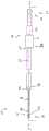
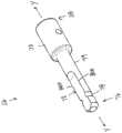
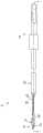
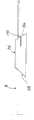
图1是处于未装载部署前构型的插入器的透视示意图;FIG1 is a perspective schematic diagram of an inserter in an unloaded, pre-deployed configuration;
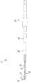
图2是处于未装载部署前构型的插入器的顶视示意图;FIG2 is a schematic top view of the inserter in an unloaded pre-deployment configuration;
图3是图2的插入器的剖视示意图;FIG3 is a schematic cross-sectional view of the inserter of FIG2 ;
图4是根据一个实施方案的插入器的远侧端部的特写顶视示意图;FIG4 is a close-up top schematic view of the distal end of an inserter according to one embodiment;
图5是根据一个实施方案的插入器的远侧端部的特写顶视透视示意图;5 is a close-up top perspective schematic diagram of the distal end of an inserter according to one embodiment;
图6A是根据一个实施方案的插入器尖端的顶视示意图;FIG6A is a schematic top view of an inserter tip according to one embodiment;
图6B是图6A的插入器尖端的剖视示意图;FIG6B is a schematic cross-sectional view of the inserter tip of FIG6A ;
图7A是根据替代实施方案的插入器尖端的顶视示意图;FIG7A is a top schematic view of an inserter tip according to an alternative embodiment;
图7B是图7A的插入器尖端的剖视示意图;FIG7B is a schematic cross-sectional view of the inserter tip of FIG7A ;
图8A是根据一个实施方案的快速更换连接器的侧视示意图;FIG8A is a schematic side view of a quick-change connector according to one embodiment;
图8B是图8A的快速更换连接器的透视示意图;FIG8B is a perspective schematic diagram of the quick-change connector of FIG8A ;
图8C是图8A的快速更换连接器的前视示意图;FIG8C is a front schematic view of the quick-change connector of FIG8A ;
图9A是根据替代实施方案的快速更换连接器的顶视透视示意图;9A is a schematic top perspective view of a quick-change connector according to an alternative embodiment;
图9B是图9A的快速更换连接器的侧视示意图;FIG9B is a schematic side view of the quick-change connector of FIG9A ;
图9C是图9A的快速更换连接器的透视示意图;FIG9C is a perspective schematic diagram of the quick-change connector of FIG9A ;
图9D是图9A的快速更换连接器的前视示意图;FIG9D is a front schematic view of the quick-change connector of FIG9A ;
图10是根据一个实施方案的在插入器上的近侧硬止挡特征的细部示意图;10 is a detailed schematic diagram of a proximal hard stop feature on an inserter according to one embodiment;
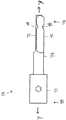
图11A是根据一个实施方案的全缝线锚的后视示意图;FIG. 11A is a schematic rear view of a full suture anchor according to one embodiment;
图11B是图11A的全缝线锚的顶视示意图;FIG11B is a schematic top view of the full suture anchor of FIG11A;
图12A是根据一个实施方案的全缝线锚的后视示意图;FIG12A is a schematic rear view of a full suture anchor according to one embodiment;
图12B是图12A的全缝线锚的顶视示意图;FIG12B is a schematic top view of the full suture anchor of FIG12A;
图13A是根据一个实施方案的装载到插入器尖端上的全缝线锚的顶视示意图;FIG13A is a top schematic view of a full suture anchor loaded onto an inserter tip according to one embodiment;
图13B是装载到图13A的插入器尖端上的全缝线锚的侧视示意图;FIG13B is a schematic side view of a full suture anchor loaded onto the inserter tip of FIG13A;
图14A是根据替代实施方案的装载到插入器尖端上的全缝线锚的顶视示意图;14A is a top schematic view of a full suture anchor loaded onto an inserter tip according to an alternative embodiment;
图14B是装载到图14A的插入器尖端上的全缝线锚的侧视示意图;FIG14B is a schematic side view of a full suture anchor loaded onto the inserter tip of FIG14A;
图15是根据一个实施方案的装载到插入器尖端上的全缝线锚的侧视示意图,其中锚部署通道处于闭合位置;15 is a schematic side view of a full suture anchor loaded onto an inserter tip with the anchor deployment channel in a closed position according to one embodiment;
图16是根据一个实施方案的在插入器上处于装载部署前构型的全缝线锚的侧视图;16 is a side view of a full suture anchor in a loaded pre-deployment configuration on an inserter according to one embodiment;
图17A是根据一个实施方案的折叠和缝合的锚编织物的顶视示意图;FIG17A is a top schematic view of a folded and stitched anchor braid according to one embodiment;
图17B是具有附加材料覆盖物的图17A的锚编织物的顶视示意图;FIG17B is a top schematic view of the anchor braid of FIG17A having an additional material covering;
图18是根据一个实施方案的处于装载部署前构型的插入器的透视示意图;18 is a perspective schematic diagram of an inserter in a loaded pre-deployment configuration according to one embodiment;
图19是根据一个实施方案的处于装载部署前构型的移除了部件的插入器的侧视示意图;19 is a schematic side view of an inserter with components removed in a loaded pre-deployment configuration according to one embodiment;
图20是根据一个实施方案的处于装载部署前构型的移除了部件的插入器的顶视示意图;20 is a top schematic view of an inserter with components removed in a loaded pre-deployment configuration according to one embodiment;
图21是图20的插入器的剖视示意图;FIG21 is a cross-sectional schematic view of the inserter of FIG20;
图22是根据一个实施方案的处于装载部署前构型的插入器的顶视示意图;FIG22 is a top schematic view of an inserter in a loaded pre-deployment configuration according to one embodiment;
图23是图22的插入器的剖视示意图;FIG23 is a cross-sectional schematic view of the inserter of FIG22;
图24是根据一个实施方案的处于装载部署前构型的插入器的顶视示意图;FIG24 is a top schematic view of an inserter in a loaded pre-deployment configuration according to one embodiment;
图25是根据替代实施方案的处于装载部署前构型的插入器的顶视和侧视示意图;25 is a schematic top and side view of an inserter in a loaded pre-deployment configuration according to an alternative embodiment;
图26是根据替代实施方案的处于装载部署前构型的插入器的透视示意图;FIG26 is a perspective schematic diagram of an inserter in a loaded pre-deployment configuration according to an alternative embodiment;
图27是根据一个实施方案的处于装载部署前构型的在骨孔位置处的插入器的侧视示意图;27 is a schematic side view of an inserter at a bone hole location in a loaded pre-deployment configuration according to one embodiment;
图28是根据一个实施方案的处于装载部署前构型的在骨孔中的插入器的侧视示意图;28 is a schematic side view of an inserter in a bone hole in a loaded pre-deployment configuration according to one embodiment;
图29是根据一个实施方案的处于未装载部署后构型的插入器的侧视示意图;FIG29 is a schematic side view of an inserter in an unloaded, post-deployment configuration according to one embodiment;
图30A是根据一个实施方案的处于未部署状态的缝线锚的实施方案的侧视示意图;FIG30A is a schematic side view of an embodiment of a suture anchor in an undeployed state according to one embodiment;
图30B是根据一个实施方案的图30A的缝线锚在部署状态下缩短和扩张的侧视示意图;30B is a schematic side view of the suture anchor of FIG. 30A shortened and expanded in a deployed state according to one embodiment;
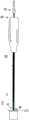
图31是根据一个实施方案的在没有快速更换连接器的情况下处于未装载部署前构型的插入器的顶视示意图;31 is a top schematic view of an inserter in an unloaded pre-deployment configuration without a quick-change connector according to one embodiment;
图32是根据一个实施方案的处于未装载部署前构型的插入器的另一个顶视示意图;32 is another top schematic view of an inserter in an unloaded, pre-deployed configuration according to one embodiment;
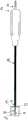
图33是根据替代实施方案的处于未装载部署前构型的插入器的顶视示意图;33 is a top schematic view of an inserter in an unloaded pre-deployment configuration according to an alternative embodiment;
图34是根据附加替代实施方案的处于未装载部署前构型的插入器的顶视示意图;34 is a top schematic view of an inserter in an unloaded pre-deployment configuration according to an additional alternative embodiment;
图35是根据一个实施方案的插入器的远侧端部的特写透视示意图;35 is a close-up perspective schematic view of the distal end of an inserter according to one embodiment;
图36A是根据一个实施方案的全缝线锚的顶视示意图;FIG36A is a top schematic view of a full suture anchor according to one embodiment;
图36B是图36A中的全缝线锚的侧视示意图;FIG36B is a schematic side view of the full suture anchor of FIG36A;
图37A是根据一个实施方案的穿过锚编织物的穿线器的顶视示意图;FIG37A is a top schematic view of a threader passing through an anchor braid according to one embodiment;
图37B是图37A的锚编织物的顶视示意图,其中第一端部装载到穿线器中;FIG37B is a top schematic view of the anchor braid of FIG37A with the first end portion loaded into the threader;
图37C是具有中心孔眼的图37A的锚编织物的顶视示意图;FIG37C is a top schematic view of the anchor braid of FIG37A having a central eyelet;
图38是具有穿过中心孔眼的一段缝线的图37C的锚编织物的顶视示意图;FIG38 is a top schematic view of the anchor braid of FIG37C with a section of suture passed through the central eyelet;
图39A是根据一个实施方案的装载有两段缝线的锚编织物的顶视示意图;FIG39A is a top schematic view of an anchor braid loaded with two lengths of suture according to one embodiment;
图39B是根据替代实施方案的装载有两段缝线的锚编织物的顶视示意图;FIG39B is a top schematic view of an anchor braid loaded with two lengths of suture according to an alternative embodiment;
图40A是根据一个实施方案的楔部件的侧视示意图;FIG40A is a schematic side view of a wedge component according to one embodiment;
图40B是根据一个实施方案的具有缝线狭缝的楔部件的侧视示意图;FIG40B is a schematic side view of a wedge component having a suture slit according to one embodiment;
图41是根据一个实施方案的处于装载部署前构型的插入器的顶视示意图;FIG41 is a top schematic view of an inserter in a loaded pre-deployment configuration according to one embodiment;
图42是根据一个实施方案的处于装载部署前构型的具有套筒的插入器的顶视示意图;42 is a top schematic view of an inserter with a sleeve in a loaded pre-deployment configuration according to one embodiment;
图43是根据一个实施方案的一次性手持件的侧视示意图;FIG43 is a schematic side view of a disposable handpiece according to one embodiment;
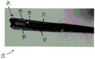
图44是根据一个实施方案的处于未装载(未装载到安装装置或插入器上)、部署前构型的软的全缝线锚的透视图数码照片;FIG44 is a perspective digital photograph of a soft, fully suture anchor in an unloaded (not loaded onto a mounting device or inserter), pre-deployment configuration according to one embodiment;
图45A是根据一个实施方案的处于部署前构型的连接到安装装置或插入器的图44的全缝线锚的实施方案的侧视示意图;45A is a side schematic view of an embodiment of the full suture anchor of FIG. 44 connected to a mounting device or inserter in a pre-deployment configuration according to one embodiment;
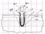
图45B是根据一个实施方案的定位在骨孔中的处于部署后构型的图44的全缝线锚的实施方案的侧视示意图;45B is a schematic side view of the embodiment of the full suture anchor of FIG. 44 in a post-deployment configuration positioned in a bone hole according to one embodiment;
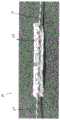
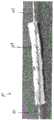
图45C是根据一个实施方案的定位在骨孔中的处于部署后构型的图1的全缝线锚的实施方案的侧视图数码照片;FIG45C is a side view digital photograph of the embodiment of the full suture anchor of FIG1 in a post-deployment configuration positioned in a bone hole according to one embodiment;
图46是根据一个实施方案的处于未装载(未装载到安装装置或插入器上)、部署前构型的软的全缝线锚的透视图数码照片;FIG. 46 is a perspective digital photograph of a soft, fully suture anchor in an unloaded (not loaded onto a mounting device or inserter), pre-deployment configuration, according to one embodiment;
图47A是根据一个实施方案的处于部署前构型的连接到安装装置或插入器的图46的全缝线锚的实施方案的侧视示意图;47A is a side schematic view of an embodiment of the full suture anchor of FIG. 46 connected to a mounting device or inserter in a pre-deployment configuration according to one embodiment;
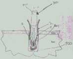
图47B是根据一个实施方案的定位在骨孔中的处于部署后构型的图46的全缝线锚的实施方案的侧视示意图;47B is a schematic side view of the embodiment of the full suture anchor of FIG. 46 in a post-deployment configuration positioned in a bone hole according to one embodiment;
图47C是根据一个实施方案的全缝线锚的替代实施方案的一部分的侧视示意图;FIG47C is a schematic side view of a portion of an alternative embodiment of a full suture anchor according to one embodiment;
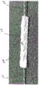
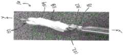
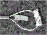
图48是根据一个实施方案的在添加激活剂之后处于部署后构型的图46的全缝线锚的实施方案的侧视图数码照片;FIG. 48 is a side view digital photograph of the embodiment of the full suture anchor of FIG. 46 in a post-deployment configuration after addition of an activating agent according to one embodiment;
图49是根据替代实施方案的全缝线锚插入装置的侧视示意图;FIG49 is a schematic side view of a full suture anchor insertion device according to an alternative embodiment;
图50是根据替代实施方案的处于部署前构型和位置的全缝线锚插入装置的透视示意图;并且50 is a perspective schematic illustration of a full suture anchor insertion device in a pre-deployment configuration and position according to an alternative embodiment; and
图51是根据替代实施方案的处于部署前构型和位置的全缝线锚插入装置的透视示意图。51 is a perspective schematic illustration of a full suture anchor insertion device in a pre-deployment configuration and position according to an alternative embodiment.
具体实施方式DETAILED DESCRIPTION
以下阐述的是涉及以下各项的示例性描述:本发明的实施方案的自钻全缝线锚和插入器的结构和功能,以及与其相关联的方法。通过本文阐述的示例性描述来说明本发明的优点。然而,特定的条件和细节将被解释为在本领域中广泛地应用,并且不应被解释为以任何方式不适当地约束或限制本发明的实施方案。Set forth below are exemplary descriptions relating to the following: the structure and function of the self-drilling full suture anchor and inserter of the embodiments of the present invention, and methods associated therewith. The advantages of the present invention are illustrated by the exemplary descriptions set forth herein. However, the specific conditions and details will be interpreted as being widely applicable in the art and should not be interpreted as unduly restricting or limiting the embodiments of the present invention in any way.
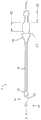
现在参见附图,其中类似的附图标号始终指代类似的部分,在图1中看到根据一个实施方案的处于未装载部署前构型的插入器10的透视示意图。插入器10通常由金属构成,诸如不锈钢或镍钛合金;然而,可以使用具有足够强度的其他合适材料来承受钻孔和插入锚所需的力(如本领域普通技术人员结合本公开的回顾应理解的)。此外,插入器10的不同特征可由不同材料构成。例如,足够小直径的镍钛合金可用于插入器10的长度12,以允许插入器10具有在弯曲导向管中通过和操作以到达期望插入位置所需的柔性。在另一示例中,可将足够大直径的不锈钢用于插入器10的长度12,以允许插入器10具有定位在期望插入位置处并在不使用导向管的情况下在其自身的支撑下操作所需的硬度。Referring now to the accompanying drawings, in which like reference numerals refer to like parts throughout, a perspective schematic diagram of an
如图1所示,插入器10包括远侧端部14,该远侧端部具有连接到轴18的插入器尖端16,该轴沿着中心纵向y-y轴线朝近侧延伸以连接到管状部分22。管状部分22在轴18和近侧端部20之间延伸。然而,在一个实施方案中,轴18在没有管状部分22的情况下延伸插入器10的整个长度,如图32-图35所示。在图31所示的另一个实施方案中,插入器10的近侧端部20在管状部分22的近侧端部24处。在这样的实施方案中,钻孔(如下所述)是通过用手持件卡盘抓握并旋转管状部分22来执行的。管状部分22可包括平坦表面,如图9A和图10所示(例如,平坦表面72),或便于与卡盘连接的其他特征。在其中轴18延伸插入器10的整个长度的实施方案中,轴18还可在插入器10的近侧端部20(即,轴18)上包括平坦表面(例如,图9A和图10中的平坦表面72)以类似地促进钻孔。然而,如图1所示和下文中所述,管状部分22可以在插入器10的近侧端部20处延伸到动力手持件接口,诸如快速更换连接器26。快速更换连接器26通常是指便于使用动力附件进行钻孔的特征。快速更换连接器26的实施方案在下面详细描述。As shown in FIG. 1 , the
现在转到图2-图3,示出了根据一个实施方案的处于未装载部署前构型的插入器10的顶视示意图和剖视示意图。如图2-图3所示,与轴18、管状部分22和快速更换连接器26相比,插入器尖端16具有相对较薄的轮廓。在图3所示的实施方案中,管状部分22还可包括但不限于外管28和内缝线管30。如图所示,缝线管30定位或以其他方式位于外管28内。因此,外管28的直径d3’大于缝线管30的直径d3”。因此,缝线管30在外管28的第一内部通道32内延伸。此外,缝线管30包括延伸穿过其中的第二内部通道34,使得外管28的第一内部通道32和缝线管30的第二内部通道34连通。重要的是要注意,缝线管30不需要附接或以其他方式直接连接到插入器尖端16或插入器10的轴18。Turning now to Fig. 2-Fig. 3, a schematic top view and a schematic cross-sectional view of the
在替代实施方案中,插入器10包括两个或更多个缝线管30,以用于维持多段缝线的分离。这样的多个缝线管30可在外管28内相对于彼此邻近、同心或呈任何其他构型。在又一个实施方案中,代替多个缝线管30,单个缝线管30包括单个多管腔挤出物,并且每个管腔包括一段缝线,以便维持多段缝线的分离。In an alternative embodiment, the
同样如图3所示,外管28的至少近侧部分36延伸到快速更换连接器26的远侧端部38中。此外,在所描绘的实施方案中,轴18的至少近侧端部40延伸到管状部分22中。具体地,在所描绘的实施方案中,轴18的近侧端部40延伸到外管28的远侧部分42和缝线管30的远侧部分44两者中。在图2所示的实施方案中,轴18包括锥形部分46。锥形部分46从管状部分22的远侧端部48延伸到插入器尖端16的近侧端部50的近侧的位置,如图2所示。锥形部分46可包括将轴18刚性地连接到外管28的外螺纹(未示出)。然而,可以使用其他连接方法,诸如过盈压配合或焊接。Also as shown in FIG. 3 , at least the proximal portion 36 of the
简要地转到图32,示出了根据一个实施方案的处于未装载部署前构型的插入器10的顶视示意图。在图32中,插入器10在近侧端部20处包括螺纹区段45。在所描绘的实施方案中,锥形部分46朝远侧延伸到外管28的接触表面47。因此,外管28(未示出)可经由螺纹区段45上的外螺纹(未示出)连接到插入器10。在图32所示的实施方案中,缝线管30被构造成装配在插入器10的近侧端部20上方和周围。Turning briefly to FIG. 32 , a top schematic view of the
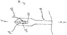
仍然参见图2,插入器尖端16包括缝线锚保持狭槽52。缝线锚保持狭槽52的尺寸被设计成或以其他方式被构造成保持锚编织物以及全缝线锚的一段缝线,从而允许将全缝线锚推入由钻孔点54A、54B(在图4中示出)在插入器10的远侧端部14(和插入器尖端16)处形成的骨孔中。Still referring to Fig. 2, the
现在转到图4-图5,示出了根据一个实施方案的插入器10的远侧端部14的特写顶视示意图和顶视透视示意图。如图4-图5所示,插入器10的远侧端部14(和插入器尖端16)包括缝线锚保持狭槽52,该缝线锚保持狭槽穿过远侧锚部署通道56延伸到钻孔点54A、54B。锚部署通道56允许将锚从插入器10移除。锚部署通道56的尺寸可被设计成等于、窄于或宽于缝线锚保持狭槽52。此外,在使用寿命期间,缝线锚保持狭槽52的尺寸可以改变。在另一个实施方案中,钻孔点54A、54B和锚部署通道56可以被构造成使得插入器10的材料响应于以闭合或打开锚部署通道56的方式施加到钻孔点54A、54B的旋转或压缩力而挠曲。Turning now to FIGS. 4-5 , a close-up top view schematic diagram and a top perspective schematic diagram of the
在图4-图5所示的实施方案中,缝线锚保持狭槽52是细长的,从而产生一对叉头58A、58B。每个叉头58A、58B围绕缝线锚保持狭槽52延伸到钻孔端部60A、60B,每个钻孔端部具有其相应的钻孔点54A、54B。因此,在所描绘的实施方案中,存在一对钻孔点54A、54B,每个钻孔点从一对尖头58A、58B中的一个延伸。钻孔点54A、54B被构造成在它们旋转时切割骨。旋转可以是插入器10的多个单方向旋转,或者旋转可以在插入器10的全部或部分旋转中顺时针和逆时针振荡。钻孔点54A、54B可具有比插入器10的其他材料更大或更小的有效直径。如图5所示,中心纵向y-y轴线至少大致延伸穿过缝线锚保持狭槽52和锚部署通道56的中心。在所描绘的实施方案中,z-z轴线垂直于中心纵向y-y轴线延伸。In the embodiment shown in Fig. 4-Fig. 5, the suture
仍然参见图5,该对叉头58A、58B中的每个包括内壁62A、62B,该内壁限定了缝线锚保持狭槽52。内壁62A、62B各自沿着与z-z轴线平行的轴线延伸。类似地,尖头58A、58B的钻孔端部60A、60B各自具有钻孔面64A、64B。钻孔面64A、64B彼此相对,并且每个钻孔面64A、64B沿着不平行于z-z轴线的轴线延伸。换句话讲,钻孔面64A、64B相对于z-z轴线成一定角度,因此相对于内壁62A、62B成一定角度。叉头58A、58B的钻孔面64A、64B限制缝线锚保持狭槽52在YZ平面中打开,从而在将插入器尖端16插入骨中的过程中锁定了锚部署通道56。此外,钻孔面64A、64B与内壁62A、62B的角度关系防止尖头58A、58B中的一个沿着平行于z-z轴线的轴线在第一方向上移动,而当施加力以闭合尖头58A、58B时,尖头58A、58B中的另一个沿着平行于z-z轴线的轴线在与第一方向相反的第二方向上移动。因此,当沿着横向x-x轴线施加力以闭合尖头58A、58B时,尖头58A、58B不能沿着平行于z-z轴线的轴线在相反方向上移动。如图5所示,横向x-x轴线垂直于中心纵向y-y轴线。Still referring to Fig. 5, each of the pair of
现在简要地转到图35,示出了根据一个实施方案的插入器10的远侧端部14的特写透视示意图。如图35所示,插入器尖端16具有带有长度L1的第一面57和带有长度L2的第二面59。具体地,L2大于L1以产生大于轴18的直径d2的有效钻孔直径d1。直径d1、d2的差值允许骨孔中的锚、缝线和轴18的间隙。Turning now briefly to FIG. 35 , a close-up perspective schematic view of the
现在转到图33-图34,示出了根据替代实施方案的处于未装载部署前构型的插入器10的顶视示意图。在图33所示的实施方案中,插入器尖端16是铲形的。与图4-图5中的插入器尖端16相比,铲形插入器尖端16允许钻孔点54A、54B钻出更大的孔,同时在钻孔点54A、54B后面提供用于锚编织物的空间。图34示出了具有偏移锚部署通道56(相对于中心纵向y-y轴线偏移)的插入器尖端16的实施方案。偏移锚部署通道56允许在第一钻孔点54A处有真实的钻孔点55。Turning now to Figures 33-34, a schematic top view of an
现在参见图6A-图6B,示出了根据一个实施方案的插入器尖端16的顶视示意图和剖视示意图。如图6A-图6B所示,缝线锚保持狭槽52包括圆形近侧边缘66和锐利远侧边缘68。锐利远侧边缘68允许插入器10容易地从骨中抽出并可靠地释放全缝线锚。特别地,锐利远侧边缘68用于切割锚编织物(不是一段缝线),使得可以在不松开或拉出全缝线锚的情况下移除插入器10。另一方面,圆形近侧边缘66在插入期间保护锚编织物。虽然图6A-图6B中所示的插入器尖端16包括锚部署通道56,但图7A-图7B的插入器尖端16不包括锚部署通道。在图7A-图7B所示的插入器尖端16的替代实施方案中,全缝线锚被装载到锚保持狭槽52中,并通过来自圆形近侧边缘66的力推进到骨中。然后,当插入器10回缩并移除时,全缝线锚被锐利远侧边缘68切割成两件。Referring now to Fig. 6A-6B, a schematic top view and a schematic cross-sectional view of an
简要地返回参见图2-图3,快速更换连接器26在其远侧端部38处包括适配器70,该远侧端部具有从其延伸到近侧端部76的杆74。现在转到图8A-图8C,示出了根据一个实施方案的快速更换连接器26的各种视图示意图。如图8A-图8C所示,适配器70与传统AO连接兼容(如本领域普通技术人员结合本公开的回顾应理解的)。然而,可以使用其他连接,诸如Trinkle或Hudson连接。杆74包括平坦表面72,该平坦表面沿着平行于中心纵向y-y轴线的轴线延伸,如图8A-图8B所示。在所描绘的实施方案中,杆74包括凹槽78。凹槽78从平坦表面72的第一边缘80A到平坦表面72的第二边缘80B延伸到杆74中。Referring briefly back to FIGS. 2-3 , the quick-
现在转到图9A-图9D,示出了根据替代实施方案的快速更换连接器26的各种视图示意图。如图9A所示,杆74包括三个平坦表面72,其具有三角形横截面(示于图9D中)。杆74还包括三个凹槽78,其在三个平坦表面72中的两个接触或以其他方式会聚的位置处延伸到杆74中,如图9A和图9C所示。同样如图9B-图9C所示,适配器70与传统AO连接兼容(可以使用其他连接)。然而,三个平坦表面72允许插入器10的中心纵向y-y轴线与延伸穿过抓紧卡盘(未示出)的中心纵向y-y轴线共线。快速更换连接器26可以由固体金属片形成(在图9B、图9C、图9D中)或形成到管材的端部中(图9A)。将快速更换连接器26形成到管材中提供了许多优点以便与插入器10一起使用。例如,近侧端部76保持打开,以允许环氧乙烷的更好流动以对容纳在管材内的缝线材料进行灭菌,并且可以减少组装插入器10所需的部件的数量。Turn now to Fig. 9A-Fig. 9D, various view schematic diagrams of
现在参见图10,示出了根据一个实施方案的在插入器10上的近侧硬止挡特征82的细部示意图。如所描绘的实施方案中所示,硬止挡特征82沿着插入器10的近侧端部20定位或以其他方式定位。硬止挡特征82在快速更换连接器26的远侧,使得硬止挡特征82防止快速更换连接器26进入或推进穿过导向器。在所描绘的实施方案中,硬止挡特征82是缠绕在插入器10的外表面84周围的环。然而,如果尺寸被设计成足够大于导向器的直径,则可以使用用于硬止挡特征82的任何其他形状或构型。Referring now to FIG. 10 , a detailed schematic diagram of a proximal hard stop feature 82 on the
简要地参见图11A-图12B,示出了根据一个实施方案的全缝线锚100的前视和后视示意图。图11A示出了全缝线锚100的后视图,而图11B示出了前视图。如图所示,进出锚编织物/纤维构造104的所述一段缝线102仅穿过锚编织物104的一个(例如,“前”)表面106(图11B)。类似地,图12A-图12B还示出了后视图(图12B)和前视图(图12A),其中缝线102仅穿过锚编织物104的一个(例如“前”)表面106(图12B)。当全缝线锚100具有仅穿过一个(例如,“前”)表面106的缝线102时,锚编织物104保护缝线102以免于在装载到插入器上时在相对(例如,“后”)表面108(图11A和图12A)上的磨损(如本领域普通技术人员结合本公开的回顾应理解的)。在图11A-图12B中,缝线102在多个通过位置处穿过锚编织物104。图13B和图14B中的通过位置的数量是八个通过位置110,而一些替代全缝线锚100的通过位置的数量是六个通过位置110。通过位置110的数量可根据缝线102和/或锚编织物104的组成和尺寸而改变。可通过平衡输入参数(诸如锚编织物长度、锚编织物宽度、锚编织物纬密度、缝线直径等)来优化通过位置110的数量,以产生输出参数(诸如可制造性、负载下的锚蠕变、以及拔拉强度)。Referring briefly to FIGS. 11A-12B , schematic front and rear views of a
简要地转到图36A-图36B,示出了根据替代实施方案的全缝线锚100的顶视和侧视示意图。如图36A-图36B所示,所述一段缝线102穿过锚编织物104的大致中心105。在所描绘的实施方案中,所述一段缝线102通过一个(例如,“前”)表面106进入锚编织物104,并且通过锚编织物104的相对(例如,“后”)表面108离开。在将所述一段缝线102定位在锚编织物104的两侧上的情况下,可将锚编织物104装载到插入器10上,使得锚编织物104可抵靠骨定位,而多段缝线102沿着插入器10,如图41所示。Turning briefly to FIGS. 36A-36B , schematic top and side views of a
在另一个替代实施方案中,如图39A-图39B所示,锚编织物104可以装载有多段缝线102A、102B。在所描绘的实施方案中,锚编织物104装载有两段缝线102A、102B。所述多段缝线102可沿着其相对边缘107A、107B(图39B)延伸穿过锚编织物104,穿过两个偏心位置109A、109B(图39A),或其任何可想象的组合(包括所述一段缝线102A、102B延伸穿过锚编织物104的大致中心105)。另外,所述多段缝线102A、102B可在相同表面(图11A-图12B)上或在相对表面(图36A-图36B)上进入/离开锚编织物104。In another alternative embodiment, as shown in FIGS. 39A-39B , the
现在参见图37A-图38,示出了根据附加替代实施方案的全缝线锚100的顶视示意图。图37A-图37C描绘了用于产生倒置锚编织物104的过程。如图37A所示,具有穿线器环130的穿线器128首先穿过锚编织物104。然后,在图37B中,锚编织物104的端部114B被拉动穿过穿线器环130。最后,穿线器环130被拉回穿过锚编织物104,从而形成中心孔眼132,如图37C所示。通过使一段缝线102穿过锚编织物104(如结合图11A-图12B、图36A-图36B和图39A-图39B所示的实施方案中的任一个所述),并且穿过中心孔眼132(如图38所示),可将所述一段缝线102装载到倒置锚编织物104上。Referring now to FIGS. 37A-38 , a schematic top view of a
返回参见图11A-图12B,从所示的未装载部署前构型,全缝线锚100被装载到插入器尖端16上,如图13A-图13B所示。为了装载插入器尖端16,锚编织物104被馈送穿过缝线锚保持狭槽52,使得缝线102的一对端部112A、112B和锚编织物104的一对端部114A、114B在缝线锚保持狭槽52(和插入器10)的相对侧上。此外,在一个实施方案中,全缝线锚100被馈送穿过缝线锚保持狭槽50,使得通过位置110中的四个在缝线锚保持狭槽52(和插入器10)的相对侧上。然后沿着轴18拉紧缝线102,这导致缝线102的一对端部112A、112B和锚编织物104的一对端部114A、114B沿着插入器10延伸(即,各自沿着大致平行于中心纵向y-y轴线的轴线)。Referring back to FIGS. 11A-12B , from the unloaded pre-deployment configuration shown, the
现在转到图14A-图14B,示出了根据替代实施方案的处于未装载部署前构型和装载部署前构型的全缝线锚的顶视示意图。图14A-图14B中示出的全缝线锚10是Y形结缝线锚。本发明的实施方案的某些结构和功能方面类似于在美国9826971中描述和示出的软缝线锚的实施方案。那些相似之处应由本领域普通技术人员结合本公开的回顾和附图,结合所公布的申请来理解,并且在本文中不会进一步详细讨论。本文和下文中参考附图进一步简要描述包括本发明的实施方案的各种发明特征的某些差异。然而,在全缝线锚100是Y形结缝线锚的实施方案中,仅锚编织物104被装载到插入器尖端16中。如图14B所示,当将锚编织物104装载在缝线锚保持狭槽52中时,将缝线102的中心部分116拉离插入器尖端16(即,沿该插入器尖端远侧的方向拉动)。这防止缝线102落入缝线锚保持狭槽52中。将缝线102保持在缝线锚保持狭槽52之外避免了由于插入器10的尖头58A、58B(图4-图5)在钻入骨中时产生的热量而对缝线102造成潜在损坏,或者避免了在移除插入器10时被切断。在一个实施方案中,一旦将全缝线锚100装载到插入器尖端16上,如图13A-图14B中的实施方案中的任一个所示,锚部署通道56便可移动到闭合位置以产生闭合的缝线锚保持狭槽52,如图15所示。在一实施方案中,通过以完全闭合锚部署通道56的方式弯曲尖头58A、58B,将锚部署通道56移动到闭合位置。Turning now to FIGS. 14A-14B , a schematic top view of a full suture anchor in an unloaded pre-deployment configuration and a loaded pre-deployment configuration according to an alternative embodiment is shown. The
现在参见图16,示出了根据一个实施方案的在插入器10上处于装载部署前构型的全缝线锚100的侧视图。如图16所示,当将全缝线锚100装载到插入器尖端16上时,锚编织物104沿着插入器尖端16扭转。当锚编织物104通过紧密扭转118被装载到插入器尖端16上时,当通过沿扭转118的方向旋转全缝线锚100来将锚编织物104插入骨中时,锚编织物104不再发生进一步的扭转。换句话讲,当锚编织物104被装载到插入器尖端16上时,该锚编织物中的扭转118防止锚编织物104在其被插入骨中时自身扭转,并且防止所述一段缝线102由于锚编织物104的扭转而自身扭转。因此,缝线102可以在不扭转的情况下离开骨孔。在所描绘的实施方案中,锚编织物104具有1.5转的扭转18,这实际上导致所述一段缝线102在插入器尖端16处没有暴露。Referring now to FIG. 16 , a side view of the
现在转到图17A-图17B,示出了根据一个实施方案的具有附加材料120的锚编织物104的顶视示意图。本领域普通技术人员应认识到并理解Y形结锚的可能实施方案,该Y形结锚具有附加材料(诸如单丝聚合物)以增加强度。可以将附加材料应用于全缝线锚104。如图17A所示,锚编织物104被对半折叠。使用单丝120将锚编织物104的每个(即,两个)侧边缘122A、122B缝合在一起,以形成封闭区域124,其中所述一段缝线102在内部,如图17B所示。除了提高强度之外,这还将防止锚编织物104在插入期间自身翻转以及使缝线102暴露于骨,从而引起磨损。另外,所描述的锚编织物104的扭转与在锚编织物104的轴线上延伸的更致密的材料相结合,可以产生带螺纹的全缝线锚100。Turning now to FIGS. 17A-17B , a top view schematic diagram of an
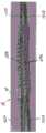
简要地转到图18,示出了根据一个实施方案的处于装载部署前构型的插入器10的透视示意图。在所描绘的实施方案中,如上所述,锚编织物104被装载到插入器尖端16上。图19示出了根据一个实施方案的处于装载部署前构型的插入器10的侧视示意图。在图19中,为了清楚起见,已经移除了外管28和快速更换连接器26。如图所示,锚编织物104延伸穿过缝线锚保持狭槽52,并且在插入器尖端16周围具有扭转118。缝线的第一端部112A和第二端部112B在缝线管30内的轴18的相对侧上延伸。在所描绘的实施方案中,端部112A、112B在缝线管30中朝远侧后退或拉动。图20-图21类似地示出了缝线管30的内部容积34内的端部112A、112B。图22-图24还示出了根据一个实施方案的处于装载部署前构型的插入器10的各种顶视和剖视示意图。外管28容纳缝线管30和缝线102的端部112A、112B,使得这些部件在插入期间可与锚编织物104一起转动、扭转或以其他方式旋转。Turning briefly to FIG. 18 , a perspective schematic diagram of an
如图19、图21和图23所示,缝线102的第一端部112A和第二端部112B从锚编织物104沿着轴18延伸并进入缝线管30。一旦在缝线管30内,缝线102的第一端部112A和第二端部112便朝向插入器尖端16后退,如图所示。在第一端部112A和第二端部112B在轴18的相对侧上并且在缝线管30内的情况下,轴18抵靠缝线管30按压并锁定分支112A、112B,从而张紧所述一段缝线102并维持锚编织物104的位置和构型。图41还示出了围绕多段缝线102和轴18延伸的缝线管30。缝线管30抵靠轴18压缩多段缝线102。尽管在图41中未示出,但缝线管30延伸缝线102的整个长度。As shown in Figures 19, 21 and 23, the
现在参见图25-图26,示出了根据替代实施方案的处于装载部署前构型的插入器10的各种视图示意图。如图25所示,轴18包括挠曲区域126。在图26所示的实施方案中,挠曲区域126在插入器10的管状部分22中延伸。因此,挠曲区域126可沿着插入器10的长度12(图1)的任何部分延伸。挠曲区域126可由例如激光切割或蚀刻的一系列小切口来形成,如图26所示。挠曲区域126增加了插入器10的柔性(如本领域普通技术人员结合本公开的回顾应理解的),使得插入器10可延伸穿过弯曲导向器。Referring now to Figures 25-26, various schematic views of the
简要地转到图40A-图40B,示出了根据插入器10的替代实施方案的楔部件134的侧视示意图。在图40A中,插入器10包括可滑动楔部件134。轴18穿过楔部件134,但未附接。楔部件134包括近侧端部136和远侧端部138。在使用中,将所述一段缝线102缠绕在近侧端部136和远侧端部138周围,以将所述一段缝线102固定在适当位置。楔部件134可通过沿着轴18滑动楔部件134而沿着插入器10朝近侧(有限制)或朝远侧移动。在图40B所示的另一个实施方案中,楔部件134包括狭槽140以保持所述一段缝线102。因此,所述一段缝线102缠绕在楔部件134的近侧端部136和远侧端部138周围,并固定在狭槽140内。在使用中,在插入器10钻出骨孔之后,使用者可从狭槽140移除所述一段缝线102,从近侧端部136和远侧端部138解开所述一段缝线102,并且移除插入器10。Turning briefly to Figures 40A-40B, a side schematic diagram of a
在图42所示的另一个实施方案中,套筒142,诸如橡胶套筒,定位在轴18、楔部件134和所述一段缝线102上方,以将所述一段缝线102保持在适当位置。如上简要所述,楔部件134(具有所述一段缝线102和套筒142)可沿着轴18朝远侧滑动。然而,由于所述一段缝线102上的张力,楔部件134沿着轴18的近侧运动受到限制。由于有限的近侧平移,套筒142的远侧表面144还用作插入器10的硬止挡件。因此,在使用中,将插入器10钻入骨中,直到硬止挡件(例如,套筒142的远侧表面144)接触导向器和轴18。当轴18从骨中移除时,锚编织物104和所述一段缝线102保留在骨中,而楔部件134和套筒142附接到所述一段缝线102。由于轴18不再穿过楔部件134定位,因此所述一段缝线102可从楔部件134和套筒142释放。In another embodiment shown in FIG. 42 , a
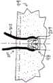
现在参见图27,示出了根据一个实施方案的处于装载部署前构型的在骨孔位置86处的插入器10的侧视示意图。如图所示,插入器10在选定骨孔位置86处延伸穿过导向器88,使得导向器88的远侧端部90定位在骨94的表面92处,而快速更换连接器26延伸穿过并经过导向器88的近侧端部96。在所描绘的实施方案中,在导向器88的远侧端部90中装载有锚编织物104的插入器尖端16定位在骨94的表面92处。一旦定位并且在导向器88相对于骨94保持静止的同时,使用者使用手持件经由快速更换连接器26旋转插入器,该手持件旋转钻孔端部60A、60B及其相应的钻孔点54A、54B,并将插入器10推动到骨94中,直到锚编织物104完全插入骨94中。诸如硬止挡特征82(图10)之类的特征通过不允许插入器10进一步穿过导向器88来限制插入深度。Referring now to FIG. 27 , a schematic side view of the
现在转到28,示出了根据一个实施方案的处于装载部署前构型的在骨孔98中的插入器10的侧视示意图。如图所示,随着插入器10在导向器88中推进,钻孔端部60A、60B及其相应的钻孔点54A、54B在骨94中形成孔98。一旦将锚编织物104插入骨孔98中,锚编织物104便迫使打开锚部署通道56,以允许移除插入器10,从而将锚留在骨孔中。在另一个实施方案中,锚部署通道56可以被诸如缝线、线或杆的细丝之类的附加物体强制打开,该附加物体在插入器10被独立地移除或致动时打开锚部署通道56。在另一个实施方案中,在插入期间,锚部署通道56可以被诸如细丝、线、杆、锚的一部分或其他材料之类的附加构件阻塞,以形成完全封闭的缝线锚保持狭槽52。当插入器10被抽出时或通过独立致动,阻塞材料可以离开锚部署通道56。最终,当锚部署通道56打开时,插入器10可通过导向器88回缩,使得插入器尖端16从骨94移除,其中当插入器10被抽出时,锚编织物104保留在骨孔98中并且穿过锚部署通道56。将锚编织物104保持在骨孔98中的力可以通过骨94与锚编织物104之间的相互作用或者通过锚编织物104与被引入以在全缝线锚100被部署之前将锚编织物104保持在适当位置的另一构件之间的相互作用来提供。Turning now to 28, a schematic side view of an
现在参见图29,示出了根据一个实施方案的处于未装载部署后构型的插入器10的侧视示意图。一旦锚编织物104被完全插入并且插入器10被移除,张力便通过以下方式而被施加到缝线102(端部112A、112B):移除插入器10,使用者直接在缝线102(端部112A、112B)上拉动,或两种手段的组合。该张力使锚编织物104部署成部署后构型以提供固定。Referring now to FIG. 29 , a schematic side view of the
现在转到图30A-图30B,示出了处于部署前和部署后构型的全缝线锚100的实施方案的侧视示意图。在所描绘的实施方案中,全缝线锚100是软缝线锚,诸如


换句话讲,锚主体204具有两个主要功能。首先,它成为缝线202在其中滑动的基础。其次,当在部署期间压缩和/或打褶时,锚主体204在一个方向上变得更紧凑,从而向外扩张并增加其总宽度、厚度或直径,以产生保持能力。使锚主体204改变形状以增加其总宽度、厚度或直径的这种作用是有用的特征,其可以有利地用于将锚200固定在孔98中或者抵靠骨组织或软组织94固定。正是扩张锚主体204与缝线202联接的这种相对于锚主体204保持可滑动(在一些实施方案中;并且在其他实施方案中,至少在使用中的特定位置或特定点处相对于该锚主体不可滑动)的组合使得本发明的实施方案理想地用于软组织再附着到骨94或软组织再附着到软组织,在这种情况下期望传递滑动结来固定修复。In other words, the anchor body 204 has two main functions. First, it becomes the basis for the
下面的讨论涉及一次性手持件的替代实施方案,可与本文所述的锚插入器的实施方案结合使用或由其部署的全缝线锚的替代实施方案,以及锚安装装置/插入器和钻的替代实施方案。The following discussion relates to alternative embodiments of disposable handpieces, alternative embodiments of full suture anchors that may be used in conjunction with or deployed by embodiments of anchor inserters described herein, and alternative embodiments of anchor installation devices/inserters and drills.
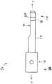
转到图43,示出了根据替代实施方案的一次性手持件300的侧视示意图。一次性手持件可包括但不限于马达301;卡盘302;一次性电池303,该一次性电池被构造成向马达供电;以及至少一个开关304,该开关被构造成由使用者致动(旋转地、线性地、垂直于装置的纵向轴线(“推动”))以接通钻头302和/或设定钻头302的期望速度。替代地,可以由使用者经由手持件300抵靠骨施加到插入器上的预定力(足以开始在特定骨中钻出孔,该孔可以根据骨的类型和硬度而变化)来致动马达。手持件300还可包括一次性塑料壳体305,以使装置重量轻、比较便宜且为一次性的。一次性塑料壳体305可以由任何塑料或塑料的组合制成。插入器也可制成一次性的,并作为套件预先附接到手持件300而提供。如本文所述,锚插入器的近侧端部可附接到一次性手持件300的卡盘302。一次性手持件可用于旋转钻孔端部60A、60B及其相应的钻孔点54A、54B,并将插入器10推动到骨94中,直到锚编织物104完全插入骨94中(如相对于图27所述)。Turning to FIG. 43 , a schematic side view of a
通常,以下描述和示出的替代全缝线锚设计被构造成以与上文所述和本文示出的其他全缝线锚相同的方式与本文所述的锚插入器一起工作并由本文所述的锚插入器部署。与其他全缝线锚一样,全缝线锚的替代实施方案可包括纤维构造锚主体部分(或纤维、编织或织造织物型结构,诸如柔性网)以及具有第一端部和第二端部的缝线或细丝部分。缝线可以以多种方式穿过细丝(包括织造、穿过柱、刺穿顶部和底部等,如本领域普通技术人员结合本公开的回顾应理解的)。纤维构造可包括第一状态,其中当处于展开和部署前状况时,纤维构造未压缩并且沿着细丝的纵向轴线延伸;以及第二状态,其中在部署状况下,平坦纤维构造在垂直于细丝的纵向轴线的方向上压缩和扩张(如本文所讨论)。In general, the alternative full suture anchor designs described and shown below are configured to work with and be deployed by the anchor inserter described herein in the same manner as other full suture anchors described above and shown herein. As with other full suture anchors, alternative embodiments of full suture anchors may include a fiber structure anchor body portion (or fiber, braided or woven fabric type structure, such as a flexible mesh) and a suture or filament portion having a first end and a second end. Sutures can be passed through the filaments in a variety of ways (including weaving, passing through a post, piercing the top and bottom, etc., as those of ordinary skill in the art should understand in conjunction with a review of this disclosure). The fiber structure may include a first state, wherein the fiber structure is uncompressed and extends along the longitudinal axis of the filament when in a pre-deployment and deployment state; and a second state, wherein in a deployed state, the flat fiber structure is compressed and expanded in a direction perpendicular to the longitudinal axis of the filament (as discussed herein).
根据一个实施方案,纤维构造具有从第一端部延伸到第二端部的开放细长柱/管腔,并且细丝穿过开放柱并至少部分地定位在该开放柱中。在实施方案中,细丝自由滑动穿过开放柱,使得可以从纤维构造的第一端部和纤维构造的第二端部从开放柱中移除细丝。纤维构造的实施方案除了具有开放细长柱/管腔外,还可以是管状的。可以将平坦带/纤维构造直接原位织造到细丝(例如,圆形区段缝线编织物)上,或者用开放柱织造,之后可以将圆形区段缝线编织物插入该开放柱中。特别地,如图44中所示,示出根据一个实施方案的处于未装载(未装载到安装装置或插入器上)、部署前构型的软的全缝线锚400的透视示意图。全缝线锚400可包括但不限于具有第一端部4A、第二端部4B的平坦纤维构造4,以及具有第一端部6A和第二端部6B的开放细长柱/管腔6(开放细长柱/管腔6的第一端部6A和第二端部6B中的每个都可以在平坦纤维构造的第一端部4A和第二端部4B之间延伸或延伸超过其)。开放细长柱/管腔6可沿着平行于平坦纤维构造4的中心轴线的轴线,或沿着该平坦纤维构造的中心轴线织造,或者可沿着不平行于中心轴线的路径织造。如图44所示,开放细长柱/管腔沿着中心轴线织造。According to one embodiment, the fiber structure has an open elongated column/lumen extending from a first end to a second end, and the filament passes through the open column and is at least partially positioned in the open column. In an embodiment, the filament slides freely through the open column so that the filament can be removed from the open column from the first end of the fiber structure and the second end of the fiber structure. The embodiment of the fiber structure can also be tubular in addition to having an open elongated column/lumen. The flat band/fiber structure can be directly woven in situ onto the filament (e.g., circular segment suture braid), or woven with an open column, after which the circular segment suture braid can be inserted into the open column. In particular, as shown in Figure 44, a perspective schematic diagram of a soft
仍然参见图44,示出了细丝2,其具有第一端部2A和第二端部2B,并且穿过开放柱6且至少部分地定位在该开放柱中。在实施方案中,细丝2自由滑动穿过开放柱6,使得可以从纤维构造2的第一端部2A和纤维构造2的第二端部2B从开放柱6中移除细丝2。根据替代实施方案,细丝被锁定并且不能滑动穿过开放柱6。Still referring to Figure 44, a
现在转到图45A和图45B,示出了处于部署前和部署后构型的全缝线锚400的实施方案的侧视示意图。如上所述,全缝线锚400包含至少两个区段:具有第一端部2A和第二端部2B的至少一根缝线2;具有第一端部4A和第二端部4B的锚主体/纤维构造4,以及从第一端部6A延伸到第二端部6B的开放细长柱/管腔6,该锚主体/纤维构造即将形成锚400的一部分,作为部署的一部分,该部分的宽度、厚度和/或直径可以增加,并且长度可以收缩。Turning now to Figures 45A and 45B, schematic side views of an embodiment of a
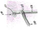
如图45A所示,提供了处于部署前构型的安装装置(或如上文所述的插入器)。全缝线锚400被示为连接到安装装置800(其可为本文所述的实施方案的插入器)的远侧部署端部804,该安装装置还包括手柄802。远侧部署端部804和全缝线锚100被示为定位在骨皮质902下方的松质骨904中的骨孔900中。为了部署全缝线锚400(其可以连接到需要与骨并置的其他组织,如本领域普通技术人员结合本公开的回顾应理解的),第一端部2A和/或第二端部2B沿远离骨孔400的方向被拉动/张紧。无论安装装置800在骨孔900中是否处于适当位置,第一端部2A和第二端部2B都可沿远离骨孔900的方向被拉动/张紧(如果安装装置800在骨孔900中处于适当位置,则其可用作对从孔900中拉出的张力的反作用力,以辅助全缝线锚400的部署)。As shown in FIG. 45A , a mounting device (or inserter as described above) is provided in a pre-deployment configuration. The
如图45B所示,锚主体/纤维构造4被示出为在部署后构型中“缩短”和“扩张”并锁定在骨孔900中,这是由于由纤维构造4(其也可为纤维构造4的一部分)形成的皱褶造成的增加的附加结果。同样参见图45C。全缝线锚400,并且特别是纤维构造4利用泊松比(如上文相对于其他锚所描述的),该泊松比捕获以下原因/效果关系:在第一方向上压缩材料导致材料在垂直于第一方向的方向上扩张(即,如果在x-方向上压缩,则材料将在y-方向和/或z-方向上扩张),并且在第一方向上拉伸/伸长材料导致材料在垂直于第一方向的方向上收缩。尽管是锚主体/纤维构造4在部署时宽度、厚度和/或直径增加,但应当理解,缝线2也可在锚400的部署中发挥作用,即使缝线2可在一些实施方案中保持自由滑动,并且在其他实施方案中(至少在使用中的特定位置或特定点处)相对于锚主体4不可滑动。缝线2帮助定位、对准和支撑锚主体4(如本领域技术人员结合本公开的回顾应理解的)。As shown in FIG. 45B , the anchor body/
换句话讲,锚主体/纤维构造体4具有两个主要功能。首先,它成为缝线2在其中(在柱/管腔6内)滑动的基础。其次,当在部署期间压缩和/或打褶时,锚主体4在一个方向上变得更紧凑,从而向外扩张并增加其总宽度、厚度或直径,以产生保持能力。使锚主体4改变形状以增加其总宽度、厚度或直径的这种作用是有用的特征,其可以有利地用于将锚400固定在孔900中或者抵靠骨组织或软组织固定。正是扩张锚主体4与缝线2联接的这种相对于锚主体4保持可滑动(在一些实施方案中;并且在其他实施方案中,至少在使用中的特定位置或特定点处相对于该锚主体不可滑动)的组合使得本发明的实施方案理想地用于软组织再附着到骨或软组织再附着到软组织,在这种情况下期望传递滑动结来固定修复。In other words, the anchor body/
在一个实施方案中,提供了利用软可植入材料的混合组合的软全缝线锚的发明构型、结构和所得功能。实施方案的混合软全缝线锚与常规软全缝线锚相比具有优越的拔出强度特性。本发明的实施方案部分地由于混合的扩张部件部分而提供了用于硬骨中的更好的软全缝线锚。这些实施方案也适用于存在非常薄或弱的皮质层的软松质骨中。混合全缝线锚可包括但不限于可扩张构件/部分,该可扩张构件/部分被构造成在施加激活剂后从第一部署前状况到第二部署状况增加尺寸;以及细丝,该细丝具有第一细丝端部和第二细丝端部,并且在第二部署状况下定位成与可扩张构件成接触关系。锚还可包括具有第一端部和第二端部的平坦纤维构造,并且其中细丝穿过纤维构造。平坦纤维构造包括第一状态,其中当处于展开和部署前状况时,平坦纤维构造未压缩并且沿着细丝的纵向轴线延伸;以及第二状态,其中在部署状况下,平坦纤维构造在垂直于细丝的纵向轴线的方向上压缩和扩张。可扩张构件以及纤维构造的结构、构型和功能(当作为实施方案的一部分时)有助于在部署后状况下将锚设置并保持在骨孔中。可扩张部分/构件可以是仅与任何细丝部分一起使用的混合全缝线锚的一部分(如本文所述)。可扩张部分/构件也可以是与任何细丝部分和任何纤维构造部分一起使用的混合全缝线锚的一部分(如本文所述)。In one embodiment, an inventive configuration, structure, and resulting functionality of a soft, all-suture anchor utilizing a hybrid combination of soft implantable materials is provided. The hybrid, soft, all-suture anchor of the embodiment has superior pull-out strength characteristics compared to conventional soft, all-suture anchors. Embodiments of the present invention provide a better soft, all-suture anchor for use in hard bone, in part due to the hybrid expansion component portion. These embodiments are also suitable for use in soft cancellous bones where a very thin or weak cortical layer is present. The hybrid all-suture anchor may include, but is not limited to, an expandable member/portion configured to increase in size from a first pre-deployment condition to a second deployment condition after application of an activator; and a filament having a first filament end and a second filament end, and positioned in contact with the expandable member in the second deployment condition. The anchor may also include a flat fiber structure having a first end and a second end, and wherein the filament passes through the fiber structure. The flat fiber structure includes a first state, wherein when in the unfolding and pre-deployment state, the flat fiber structure is uncompressed and extends along the longitudinal axis of the filament; and a second state, wherein in the deployment state, the flat fiber structure is compressed and expanded in a direction perpendicular to the longitudinal axis of the filament. The structure, configuration and function of the expandable member and the fiber structure (when as part of the embodiment) help to set and maintain the anchor in the bone hole in the post-deployment state. The expandable portion/member can be a part of a hybrid full suture anchor used only with any filament portion (as described herein). The expandable portion/member can also be a part of a hybrid full suture anchor used with any filament portion and any fiber structure portion (as described herein).
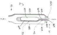
例如,参见图46,示出根据一个实施方案的处于部署前构型的混合软全缝线锚500的透视图。混合全缝线锚500可包括但不限于具有第一端部4A、第二端部4B的平坦纤维构造4。细丝2被示为具有第一端部2A和第二端部2B,并且在通过位置25、27和25、28处织造、穿线或以其他方式穿过纤维构造4。对于细丝和纤维构造的结构方面的进一步描述,参见美国9826971,这是本发明的该示例的一部分(如本领域普通技术人员结合本公开的回顾应理解的)。For example, referring to FIG. 46 , a perspective view of a hybrid soft all-suture anchor 500 in a pre-deployment configuration according to one embodiment is shown. The hybrid all-suture anchor 500 may include, but is not limited to, a
在实施方案中,细丝2自由滑动通过纤维构造4(以及当附接到其上时的可扩张部分3),使得可以从纤维构造4的第一端部4A和/或纤维构造4的第二端部4B从纤维构造4移除细丝2。根据替代实施方案,细丝被锁定并且不可滑动通过纤维构造4和/或可扩张部分3(当附接到可扩张部分3时)。In an embodiment, the
现在转到图47A和图47B,示出了处于部署前和部署后构型的全缝线锚500的实施方案的侧视示意图。如上所述,全缝线锚500包含至少两个区段:具有第一端部2A和第二端部2B的至少一根缝线2;具有第一端部4A和第二端部4B的锚主体/纤维构造4,该锚主体/纤维构造被构造成形成锚500的一部分,作为部署的一部分,该部分的宽度、厚度和/或直径可以增加,并且长度可以收缩。全缝线锚500还包括可扩张部分3,该可扩张部分被构造成形成锚500的一部分,该部分可以响应于激活剂而在部署后构型中增加尺寸(如本领域普通技术人员结合本公开的回顾应理解的)。Turning now to FIGS. 47A and 47B , schematic side views of an embodiment of a full suture anchor 500 are shown in pre-deployment and post-deployment configurations. As described above, the full suture anchor 500 comprises at least two sections: at least one
如图47A所示,提供了处于部署前构型的安装装置(或如上文所述的插入器)。全缝线锚500被示为连接到安装装置800(其可为如上文所述的插入器)的远侧部署端部804,该安装装置还包括手柄802。远侧部署端部804和全缝线锚500被示为定位在骨皮质902下方的松质骨904中的骨孔900中。为了部署全缝线锚500(其可以连接到需要与骨并置的其他组织,如本领域普通技术人员结合本公开的回顾应理解的),第一端部2A和/或第二端部2B沿远离骨孔400的方向被拉动/张紧。无论安装装置800在骨孔900中是否处于适当位置,第一端部2A和第二端部2B都可沿远离骨孔900的方向被拉动/张紧(如果安装装置800在骨孔900中处于适当位置,则其可用作对从孔900中拉出的张力的反作用力,以辅助全缝线锚500的部署)。另外,可以将激活剂添加到锚,以使可扩张部分扩张到大于第一部署前尺寸的第二尺寸。在一个实施方案中,激活剂是水。As shown in FIG. 47A , a mounting device (or inserter as described above) is provided in a pre-deployment configuration. The full suture anchor 500 is shown connected to a distal deployment end 804 of a mounting device 800 (which may be an inserter as described above), which also includes a handle 802. The distal deployment end 804 and the full suture anchor 500 are shown positioned in a
如图47B所示,锚主体/纤维构造4被示出为在部署后构型中“缩短”和“扩张”并锁定在骨孔900中,这是由于由纤维构造4(其也可为纤维构造4的一部分)形成的皱褶造成的增加的附加结果。全缝线锚500,并且特别是纤维构造4利用泊松比(类似地,如上所述),该泊松比捕获以下原因/效果关系:在第一方向上压缩材料导致材料在垂直于第一方向的方向上扩张(即,如果在x-方向上压缩,则材料将在y-方向和/或z-方向上扩张),并且在第一方向上拉伸/伸长材料导致材料在垂直于第一方向的方向上收缩。尽管是锚主体/纤维构造4在部署时宽度、厚度和/或直径增加,但应当理解,缝线2也可在锚500的部署中发挥作用,即使缝线2可在一些实施方案中保持自由滑动,并且在其他实施方案中(至少在使用中的特定位置或特定点处)相对于锚主体4不可滑动。缝线2帮助定位、对准和支撑锚主体4(如本领域技术人员结合本公开的回顾应理解的)。As shown in FIG. 47B , the anchor body/
换句话讲,锚主体/纤维构造体4具有两个主要功能。首先,它成为缝线2在其中(在柱/管腔6内)滑动的基础。其次,当在部署期间压缩和/或打褶时,锚主体4在一个方向上变得更紧凑,从而向外扩张并增加其总宽度、厚度或直径,以产生保持能力。使锚主体4改变形状以增加其总宽度、厚度或直径的这种作用是有用的特征,其可以有利地用于将锚500固定在孔900中或者抵靠骨组织或软组织固定。正是扩张锚主体4与缝线2联接的这种相对于锚主体804保持可滑动(在一些实施方案中;并且在其他实施方案中,至少在使用中的特定位置或特定点处相对于该锚主体不可滑动)的组合使得本发明的实施方案理想地用于软组织再附着到骨或软组织再附着到软组织,在这种情况下期望传递滑动结来固定修复。In other words, the anchor body/
仍然参见图47B,在暴露于激活剂之后,可扩张部分3被示为扩张的第二尺寸,大于第一较小的部署前尺寸。当暴露于激活剂时,可扩张部分的容积大大扩张,从而导致其楔入骨孔900中并将锚500锁定在适当位置。根据一个实施方案,为了张紧细丝2以重新附接软组织(未示出),细丝2可自由地向前和向后滑动通过纤维构造4和通过可扩张部分3(如连接到可扩张部分3时可能需要的)。在不存在纤维构造4的某些情况下,自由滑动细丝2可能会切割穿过可扩张部分3,从而导致全缝线锚500的部署不到最佳。因此,在具有或不具有纤维构造4的全缝线锚500的一些实施方案中,第二短段缝线2-1可以围绕细丝2(参见图47C)缠绕或环绕,以防止当与可扩张部分3接触时由细丝2锯切/切割穿过可扩张部分3。Still referring to FIG. 47B , after exposure to the activating agent, the expandable portion 3 is shown as an expanded second size, larger than the first smaller pre-deployment size. When exposed to the activating agent, the volume of the expandable portion is greatly expanded, causing it to wedge into the
转到图48,示出了根据一个实施方案的在添加激活剂之后处于部署后构型的图46的全缝线锚的实施方案的侧视图数码照片。如图所示,可扩张部分3的尺寸增加到第二部署结构状况(未示出骨孔来说明可扩张部分3的扩张程度),并且细丝2被定位成穿过可扩张部分3和/或以其他方式与该可扩张部分成接触关系。Turning to Figure 48, a side view digital photograph of the embodiment of the full suture anchor of Figure 46 in a deployed configuration after adding an activating agent according to one embodiment is shown. As shown, the size of the expandable portion 3 is increased to a second deployed configuration condition (bone holes are not shown to illustrate the degree of expansion of the expandable portion 3), and the
相对于上述细丝2和纤维构造4以及图47A-C所示的实施方案,类似地,可扩张部分3可以是本文所述的任何全缝线锚的一部分,或者以其他方式包括美国专利申请号16/033616中所示和所述的全缝线锚。上述和图47A-C所示的可扩张部分3的相同结构和功能可应用于全缝线锚(具有和不具有纤维构造)的这些实施方案。With respect to the above-described
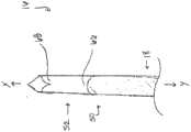
根据本发明的替代实施方案,提供了全缝线锚插入装置600,如图49-图51所示。全缝线锚插入装置600被构造成在期望锚部署位置中钻出骨孔,并且用一个装置以一个动作将全缝线锚(其可包括如本文所讨论、参考、描述和/或示出的任何全缝线锚)部署在骨孔中。在涉及将软组织固定在四肢中的许多手术中,常见的问题是外科医生在移除钻和导向器后会丢失他们在骨中钻孔以进行锚部署的孔的位置。另外,在典型的锚插入期间,必须用一只手保持钻孔导向器,而另一只手用于钻出引导孔并插入锚。全缝线锚插入装置600将导向器结合到锚中,该导向器允许单手完成手术。全缝线锚插入装置600还通过将钻孔步骤和锚插入步骤组合成一个步骤而减少了安装锚所需的时间。全缝线锚插入装置600的独特性部分地涉及使用锚驱动器杆601以通过在钻上震荡其来钻出骨隧道。钻的振荡运动使锚驱动器杆601来回旋转。当驱动器杆601震荡时,在装置的远侧端部处的叉603-1的尖端充当钻头,以在外科医生使用者将其推动到骨中时形成孔。当杆和锚(定位在装置的远侧端部处,未示出)已插入时,振荡停止,并且驱动器杆601被拉出。然后通过在锚的缝线尾部上拉动和/或添加激活剂来设置全缝线锚(如本文所讨论的)。According to an alternative embodiment of the present invention, a full suture
简而言之,如图49-图51所示,全缝线锚插入装置600包括但不限于锚驱动器杆601,具有手柄和缝线楔的导向器602,滑动导向尖端603,金属导向管604以及单个装载的全缝线锚(未示出,优选地定位在叉603-1附近的远侧端部上)。滑动导向尖端603可用于在开始使装置振荡之前定位全缝线锚,并且在锚正在振荡并被插入时保护任何周围组织。In short, as shown in Figures 49-51, the full suture
全缝线锚插入装置600的优选功能是允许在外科医生使用其的方法中以最少步骤插入锚。简而言之,外科医生可将具有相等震荡模式的动力手持件(未示出,例如如上所述,或以其他方式由本领域普通技术人员结合本公开的回顾所理解的)连接到插入器杆601的后端部。然后,保持导向器手柄602和动力手持件,外科医生可将滑动导向尖端603定位在骨中的某个位置处,并以他们想要安装锚的角度定位。然后,外科医生可以接通手持件的振荡模式,并将插入器杆601推动到骨(未示出)中。当金属导向管604变得与骨表面齐平(并且滑动导向尖端603的远侧端部与金属导向管的远侧端部齐平)时,可以停止振荡,将缝线(未示出)从楔中移除,并且移除装置。然后可通过在缝线尾部上拉动和/或添加激活剂来设置锚(如此处和上文所述)。The preferred function of the full suture
缝线材料、缝线或细丝,当这些术语在本文中使用和描述时可以包括单丝或多丝缝线以及适用于执行缝线功能的任何其他金属或非金属的细丝材料或线状材料。该材料可以包括可生物吸收和不可吸收的材料,并且可以是圆形、平坦或编织的。Suture material, suture or filament, as these terms are used and described herein, can include monofilament or multifilament suture and any other metallic or non-metallic filament or thread material suitable for performing the function of a suture. The material can include bioabsorbable and non-absorbable materials and can be round, flat or braided.
尽管已经参考某些示例性实施方案具体示出并描述了本发明的实施方案,但是本领域技术人员将理解,在不脱离可以由书面描述和附图支持的权利要求所限定的本发明的精神和范围的情况下,可以在其中进行各种细节的改变。此外,在参考一定数量的元件描述示例性实施方案的情况下,将理解,可以利用少于或大于一定数量的元件来实践示例性实施方案。Although embodiments of the present invention have been specifically shown and described with reference to certain exemplary embodiments, it will be appreciated by those skilled in the art that various changes in detail may be made therein without departing from the spirit and scope of the present invention as defined by the claims supported by the written description and the accompanying drawings. In addition, where exemplary embodiments are described with reference to a certain number of elements, it will be appreciated that the exemplary embodiments may be practiced with less than or greater than the certain number of elements.
Claims (6)
Translated fromChinesePriority Applications (1)
| Application Number | Priority Date | Filing Date | Title |
|---|---|---|---|
| CN202310810653.5ACN116942244A (en) | 2017-07-24 | 2018-07-24 | Self drilling anchor inserter system |
Applications Claiming Priority (11)
| Application Number | Priority Date | Filing Date | Title |
|---|---|---|---|
| US201762536208P | 2017-07-24 | 2017-07-24 | |
| US62/536,208 | 2017-07-24 | ||
| US201762543516P | 2017-08-10 | 2017-08-10 | |
| US62/543,516 | 2017-08-10 | ||
| US201762572369P | 2017-10-13 | 2017-10-13 | |
| US62/572,369 | 2017-10-13 | ||
| US201862618851P | 2018-01-18 | 2018-01-18 | |
| US62/618,851 | 2018-01-18 | ||
| US201862631034P | 2018-02-15 | 2018-02-15 | |
| US62/631,034 | 2018-02-15 | ||
| PCT/US2018/043446WO2019023205A1 (en) | 2017-07-24 | 2018-07-24 | Self-drilling all-suture anchor inserter |
Related Child Applications (1)
| Application Number | Title | Priority Date | Filing Date |
|---|---|---|---|
| CN202310810653.5ADivisionCN116942244A (en) | 2017-07-24 | 2018-07-24 | Self drilling anchor inserter system |
Publications (2)
| Publication Number | Publication Date |
|---|---|
| CN111163705A CN111163705A (en) | 2020-05-15 |
| CN111163705Btrue CN111163705B (en) | 2023-07-14 |
Family
ID=63165489
Family Applications (2)
| Application Number | Title | Priority Date | Filing Date |
|---|---|---|---|
| CN201880058880.4AActiveCN111163705B (en) | 2017-07-24 | 2018-07-24 | Self Drilling Full Suture Anchor Inserter |
| CN202310810653.5APendingCN116942244A (en) | 2017-07-24 | 2018-07-24 | Self drilling anchor inserter system |
Family Applications After (1)
| Application Number | Title | Priority Date | Filing Date |
|---|---|---|---|
| CN202310810653.5APendingCN116942244A (en) | 2017-07-24 | 2018-07-24 | Self drilling anchor inserter system |
Country Status (8)
| Country | Link |
|---|---|
| US (1) | US11723646B2 (en) |
| EP (1) | EP3658040A1 (en) |
| JP (3) | JP6946547B2 (en) |
| KR (3) | KR102533859B1 (en) |
| CN (2) | CN111163705B (en) |
| AU (3) | AU2018307917B2 (en) |
| CA (2) | CA3071147A1 (en) |
| WO (1) | WO2019023205A1 (en) |
Families Citing this family (12)
| Publication number | Priority date | Publication date | Assignee | Title |
|---|---|---|---|---|
| KR102590796B1 (en)* | 2018-05-09 | 2023-10-17 | 콘메드 코포레이션 | Molded suture pass and drill |
| US11039842B1 (en)* | 2018-10-29 | 2021-06-22 | Smith & Nephew, Inc. | Surgical drill bit having dual cutting elements with opposite hand rotation |
| US12295564B2 (en)* | 2018-12-18 | 2025-05-13 | Conmed Corporation | Self-drilling anchor inserter |
| WO2021003382A1 (en)* | 2019-07-02 | 2021-01-07 | Conmed Corporation | Automated anchor insertion system |
| FR3107176B1 (en)* | 2020-02-14 | 2022-03-04 | Teknimed | ANCHORAGE DEVICE FOR SOFT TISSUE REPAIR |
| JP7451769B2 (en)* | 2020-06-02 | 2024-03-18 | コンメッド コーポレーション | Self-drilling row anchors and anchor drivers |
| WO2022130954A1 (en)* | 2020-12-18 | 2022-06-23 | ニプロ株式会社 | Handset for medical use |
| CN115737030A (en)* | 2021-02-04 | 2023-03-07 | 杭州锐健马斯汀医疗器材有限公司 | Suture anchor implantation device |
| CN113208675B (en)* | 2021-05-24 | 2022-05-10 | 杭州锐健马斯汀医疗器材有限公司 | Device is implanted to compound suture anchor |
| CN115429354A (en)* | 2022-09-23 | 2022-12-06 | 余洪猛 | Soft tissue stitching instrument |
| CN116269562A (en)* | 2023-01-18 | 2023-06-23 | 杭州锐健马斯汀医疗器材有限公司 | Implant device |
| CN119235386B (en)* | 2024-12-05 | 2025-02-14 | 北京天星医疗股份有限公司 | Full suture anchor assembly device, full suture anchor implantation device and assembly method |
Citations (3)
| Publication number | Priority date | Publication date | Assignee | Title |
|---|---|---|---|---|
| EP0611551A1 (en)* | 1993-02-17 | 1994-08-24 | United States Surgical Corporation | Suture anchor installation system |
| CN102159142A (en)* | 2008-09-18 | 2011-08-17 | 史密夫和内修有限公司 | Suture anchor inserter |
| WO2013120004A1 (en)* | 2012-02-08 | 2013-08-15 | Imds Corporation | Curved arthroscopic burr |
Family Cites Families (52)
| Publication number | Priority date | Publication date | Assignee | Title |
|---|---|---|---|---|
| US5520693A (en) | 1992-02-19 | 1996-05-28 | Mcguire; David A. | Femoral guide and methods of precisely forming bone tunnels in cruciate ligament reconstruction of the knee |
| US5411523A (en) | 1994-04-11 | 1995-05-02 | Mitek Surgical Products, Inc. | Suture anchor and driver combination |
| JP3670018B2 (en) | 1995-02-23 | 2005-07-13 | ミテック・サージカル・プロダクツ・インコーポレーテッド | Suture anchor assembly |
| US5591207A (en) | 1995-03-30 | 1997-01-07 | Linvatec Corporation | Driving system for inserting threaded suture anchors |
| US5904704A (en) | 1995-08-14 | 1999-05-18 | Mitek Surgical Products, Inc. | Suture anchor assembly |
| CA2358387C (en) | 1998-12-31 | 2007-11-13 | Jeffrey E. Yeung | Tissue fastening devices and delivery means |
| US6156039A (en) | 1999-08-06 | 2000-12-05 | Thal; Raymond | Snagging knotless suture anchor assembly |
| US6736829B1 (en) | 1999-11-11 | 2004-05-18 | Linvatec Corporation | Toggle anchor and tool for insertion thereof |
| US6287324B1 (en) | 2000-01-28 | 2001-09-11 | Shoulderon Ltd. | Self-drilling surgical suture anchor |
| US6508830B2 (en)* | 2001-04-30 | 2003-01-21 | Musculoskeletal Transplant Foundation | Suture anchor |
| US7749250B2 (en) | 2006-02-03 | 2010-07-06 | Biomet Sports Medicine, Llc | Soft tissue repair assembly and associated method |
| US7857830B2 (en) | 2006-02-03 | 2010-12-28 | Biomet Sports Medicine, Llc | Soft tissue repair and conduit device |
| DE102005021885A1 (en)* | 2005-05-04 | 2006-11-16 | Karl Storz Gmbh & Co. Kg | Device for introducing an anchor element together with thread in a bone |
| EP1832246B1 (en) | 2006-03-08 | 2019-06-12 | Arthrex, Inc. | Bundle graft and method of making same |
| US8597298B2 (en)* | 2006-09-29 | 2013-12-03 | DePuy Synthes Products, LLC | Proximal reamer |
| DE102007058256A1 (en) | 2007-11-26 | 2009-05-28 | Aesculap Ag | Surgical thread mesh |
| GB2458878A (en) | 2008-03-04 | 2009-10-07 | Xiros Plc | An implantable prosthetic cord |
| US8409252B2 (en) | 2008-03-25 | 2013-04-02 | Linvatec Corporation | Knotless suture anchor |
| GB2464952A (en) | 2008-10-30 | 2010-05-05 | Xiros Plc | Surgical cord |
| US9044224B2 (en) | 2010-04-12 | 2015-06-02 | Covidien Lp | Barbed medical device and method |
| CN103079481B (en)* | 2010-08-17 | 2015-11-25 | 雷迪恩斯医药有限责任公司 | For soft tissue being attached to the method and apparatus on bone |
| US9271714B2 (en) | 2011-01-21 | 2016-03-01 | Syntorr, Inc. | Methods and devices for anchoring suture in bone |
| US8795334B2 (en) | 2011-01-28 | 2014-08-05 | Smith & Nephew, Inc. | Tissue repair |
| US8591545B2 (en) | 2011-03-25 | 2013-11-26 | Smith & Nephew, Inc. | Flat suture anchor |
| US20130018416A1 (en) | 2011-04-15 | 2013-01-17 | Linvatec Corporation | Soft suture anchor made of braided or monofilament suture |
| EP2704640B1 (en)* | 2011-05-06 | 2021-07-07 | Linvatec Corporation | Soft anchor made from suture filament and suture tape |
| CA2840186A1 (en) | 2011-06-23 | 2012-12-27 | DePuy Synthes Products, LLC | Suture anchor system and method |
| US9421008B2 (en) | 2011-09-23 | 2016-08-23 | Arthrex, Inc. | Soft suture-based anchors |
| US9445803B2 (en) | 2011-11-23 | 2016-09-20 | Howmedica Osteonics Corp. | Filamentary suture anchor |
| US9265494B2 (en) | 2011-12-20 | 2016-02-23 | Medos International Sarl | Knotless instability anchor |
| US9084597B2 (en) | 2012-03-09 | 2015-07-21 | Smith & Nephew, Inc. | Suture-based knotless repair |
| US9585654B2 (en) | 2012-05-01 | 2017-03-07 | Dean & Webb, LLC | Segmentally rigid suture and suturing technique |
| US9421010B2 (en) | 2012-06-20 | 2016-08-23 | Arthrex, Inc. | Whipping suture anchor |
| US20130345751A1 (en) | 2012-06-20 | 2013-12-26 | Tornier, Inc. | Suture anchor insertion apparatus, suture anchor, and methods of using the same |
| US9320512B2 (en) | 2012-08-17 | 2016-04-26 | Arthrex, Inc. | Self-cinching soft anchors |
| US8986327B2 (en)* | 2012-10-18 | 2015-03-24 | Smith & Nephew, Inc. | Flexible anchor delivery system |
| US9173652B2 (en)* | 2013-03-11 | 2015-11-03 | Linvatec Corporation | All-suture anchor inserter |
| US10182806B2 (en) | 2013-03-12 | 2019-01-22 | Arthrocare Corporation | Tissue repair assembly |
| WO2015013385A1 (en) | 2013-07-24 | 2015-01-29 | Arthrex, Inc. | Hybrid suture with monofilament and braided construction |
| US20150066079A1 (en) | 2013-08-27 | 2015-03-05 | Arthrex, Inc. | Suture tape with exterior suture strands |
| EP3082617B1 (en) | 2013-12-19 | 2022-11-16 | Tornier, Inc. | High-strength bioabsorbable suture |
| WO2016038614A2 (en) | 2014-09-09 | 2016-03-17 | Mininvasive Ltd. | Padded transosseous suture |
| US20160157844A1 (en) | 2014-12-03 | 2016-06-09 | Smith & Nephew, Inc. | Sock anchor and method |
| US10568616B2 (en)* | 2014-12-17 | 2020-02-25 | Howmedica Osteonics Corp. | Instruments and methods of soft tissue fixation |
| WO2016154099A2 (en) | 2015-03-22 | 2016-09-29 | Conmed Corporation | Suture anchor comprising suture filament and suture tape |
| US20170055975A1 (en) | 2015-09-02 | 2017-03-02 | Raymond Thal | Adjustable, locking all-suture anchor assembly and method for repair |
| US20170071590A1 (en) | 2015-09-10 | 2017-03-16 | Suture Armor Llc | Suture anchor |
| AU2016381442B2 (en) | 2015-12-28 | 2019-08-01 | Conmed Corporation | Suture tape construct for providing anchor with non-sliding suture tape |
| US10258326B2 (en) | 2016-02-08 | 2019-04-16 | Ethicon, Inc. | Elastic tissue reinforcing fastener |
| US10383619B2 (en) | 2016-04-06 | 2019-08-20 | Raymond Thal | Modified adjustable, locking all-suture anchor assembly and method for repair |
| US20180049734A1 (en) | 2016-08-16 | 2018-02-22 | Conmed Corporation | Method and Device for Securing Suture to an Anchor Body of a Suture Anchor |
| US10722343B2 (en) | 2017-02-22 | 2020-07-28 | Stryker Corporation | Fixation member with separate eyelet and methods of use thereof |
- 2018
- 2018-07-24USUS16/634,306patent/US11723646B2/enactiveActive
- 2018-07-24CACA3071147Apatent/CA3071147A1/enactivePending
- 2018-07-24CNCN201880058880.4Apatent/CN111163705B/enactiveActive
- 2018-07-24KRKR1020227000010Apatent/KR102533859B1/enactiveActive
- 2018-07-24EPEP18752935.9Apatent/EP3658040A1/enactivePending
- 2018-07-24WOPCT/US2018/043446patent/WO2019023205A1/ennot_activeCeased
- 2018-07-24JPJP2020503792Apatent/JP6946547B2/enactiveActive
- 2018-07-24AUAU2018307917Apatent/AU2018307917B2/enactiveActive
- 2018-07-24CNCN202310810653.5Apatent/CN116942244A/enactivePending
- 2018-07-24CACA3189339Apatent/CA3189339A1/enactivePending
- 2018-07-24KRKR1020237016215Apatent/KR102744071B1/enactiveActive
- 2018-07-24KRKR1020207004199Apatent/KR102349096B1/enactiveActive
- 2021
- 2021-09-15JPJP2021150114Apatent/JP7297022B2/enactiveActive
- 2021-10-20AUAU2021254595Apatent/AU2021254595B2/enactiveActive
- 2023
- 2023-06-13JPJP2023096642Apatent/JP7693750B2/enactiveActive
- 2024
- 2024-03-08AUAU2024201559Apatent/AU2024201559A1/enactivePending
Patent Citations (3)
| Publication number | Priority date | Publication date | Assignee | Title |
|---|---|---|---|---|
| EP0611551A1 (en)* | 1993-02-17 | 1994-08-24 | United States Surgical Corporation | Suture anchor installation system |
| CN102159142A (en)* | 2008-09-18 | 2011-08-17 | 史密夫和内修有限公司 | Suture anchor inserter |
| WO2013120004A1 (en)* | 2012-02-08 | 2013-08-15 | Imds Corporation | Curved arthroscopic burr |
Also Published As
| Publication number | Publication date |
|---|---|
| AU2018307917A1 (en) | 2020-02-13 |
| JP7693750B2 (en) | 2025-06-17 |
| KR20200029538A (en) | 2020-03-18 |
| KR102349096B1 (en) | 2022-01-11 |
| JP2021192834A (en) | 2021-12-23 |
| AU2024201559A1 (en) | 2024-03-28 |
| CN116942244A (en) | 2023-10-27 |
| KR20220004234A (en) | 2022-01-11 |
| JP2023113926A (en) | 2023-08-16 |
| KR20230070531A (en) | 2023-05-23 |
| EP3658040A1 (en) | 2020-06-03 |
| AU2018307917B2 (en) | 2021-07-15 |
| CA3189339A1 (en) | 2019-01-31 |
| KR102533859B1 (en) | 2023-05-17 |
| KR102744071B1 (en) | 2024-12-18 |
| CA3071147A1 (en) | 2019-01-31 |
| JP6946547B2 (en) | 2021-10-06 |
| US20200360008A1 (en) | 2020-11-19 |
| AU2021254595B2 (en) | 2023-12-14 |
| JP7297022B2 (en) | 2023-06-23 |
| US11723646B2 (en) | 2023-08-15 |
| CN111163705A (en) | 2020-05-15 |
| AU2021254595A1 (en) | 2021-11-11 |
| WO2019023205A1 (en) | 2019-01-31 |
| JP2020530784A (en) | 2020-10-29 |
Similar Documents
| Publication | Publication Date | Title |
|---|---|---|
| CN111163705B (en) | Self Drilling Full Suture Anchor Inserter | |
| JP2025061411A (en) | Self-drilling anchor inserter | |
| CN111225620B (en) | Mixed suture anchor | |
| US12245780B2 (en) | Multi-barrel drill guide and anchor deployment assembly | |
| WO2021150257A1 (en) | Self-drilling anchor inserter |
Legal Events
| Date | Code | Title | Description |
|---|---|---|---|
| PB01 | Publication | ||
| PB01 | Publication | ||
| SE01 | Entry into force of request for substantive examination | ||
| SE01 | Entry into force of request for substantive examination | ||
| GR01 | Patent grant | ||
| GR01 | Patent grant |