CN111158108A - Optical imaging lens - Google Patents
Optical imaging lensDownload PDFInfo
- Publication number
- CN111158108A CN111158108ACN202010057670.2ACN202010057670ACN111158108ACN 111158108 ACN111158108 ACN 111158108ACN 202010057670 ACN202010057670 ACN 202010057670ACN 111158108 ACN111158108 ACN 111158108A
- Authority
- CN
- China
- Prior art keywords
- lens
- object side
- image side
- convex
- refractive index
- Prior art date
- Legal status (The legal status is an assumption and is not a legal conclusion. Google has not performed a legal analysis and makes no representation as to the accuracy of the status listed.)
- Granted
Links
Images


Classifications
- G—PHYSICS
- G02—OPTICS
- G02B—OPTICAL ELEMENTS, SYSTEMS OR APPARATUS
- G02B13/00—Optical objectives specially designed for the purposes specified below
- G02B13/001—Miniaturised objectives for electronic devices, e.g. portable telephones, webcams, PDAs, small digital cameras
- G02B13/0015—Miniaturised objectives for electronic devices, e.g. portable telephones, webcams, PDAs, small digital cameras characterised by the lens design
- G02B13/005—Miniaturised objectives for electronic devices, e.g. portable telephones, webcams, PDAs, small digital cameras characterised by the lens design having spherical lenses only
- G—PHYSICS
- G02—OPTICS
- G02B—OPTICAL ELEMENTS, SYSTEMS OR APPARATUS
- G02B13/00—Optical objectives specially designed for the purposes specified below
- G02B13/001—Miniaturised objectives for electronic devices, e.g. portable telephones, webcams, PDAs, small digital cameras
- G02B13/0055—Miniaturised objectives for electronic devices, e.g. portable telephones, webcams, PDAs, small digital cameras employing a special optical element
- G02B13/006—Miniaturised objectives for electronic devices, e.g. portable telephones, webcams, PDAs, small digital cameras employing a special optical element at least one element being a compound optical element, e.g. cemented elements
- G—PHYSICS
- G02—OPTICS
- G02B—OPTICAL ELEMENTS, SYSTEMS OR APPARATUS
- G02B7/00—Mountings, adjusting means, or light-tight connections, for optical elements
- G02B7/02—Mountings, adjusting means, or light-tight connections, for optical elements for lenses
- G02B7/021—Mountings, adjusting means, or light-tight connections, for optical elements for lenses for more than one lens
Landscapes
- Physics & Mathematics (AREA)
- General Physics & Mathematics (AREA)
- Optics & Photonics (AREA)
- Lenses (AREA)
Abstract
Description
Translated fromChinese技术领域technical field
本发明涉及光学成像技术领域,具体是涉及一种光学成像镜头。The invention relates to the technical field of optical imaging, in particular to an optical imaging lens.
背景技术Background technique
随着技术的不断进步,近年来,光学成像镜头也得到了迅猛发展,被广泛应用在智能手机、平板电脑、视频会议、安防监控等各个领域,因此,对于光学成像镜头的要求也越来越高。With the continuous advancement of technology, optical imaging lenses have also developed rapidly in recent years, and are widely used in smartphones, tablet computers, video conferencing, security monitoring and other fields. Therefore, the requirements for optical imaging lenses are also increasing. high.
但目前应用于智能交通领域的ITS至少还存在有以下缺陷:However, the ITS currently used in the field of intelligent transportation still has at least the following defects:
1.现有的ITS镜头25mm焦距段像面较小,普遍为1/1.7英寸至1.1英寸;1. The 25mm focal length of the existing ITS lens has a small image area, generally 1/1.7 inches to 1.1 inches;
2.现有的ITS镜头对传递函数管控不好,分辨率低;2. The existing ITS lens has poor control over the transfer function and low resolution;
3.现有的ITS镜头的通光普遍比较小,低照环境下,进光亮较低,拍摄图面较暗;3. Existing ITS lenses generally have relatively small light penetration, and in low-light environments, the incoming light is low, and the shooting surface is dark;
4.现有的ITS镜头为满足高分辨率,镜片多且复杂,导致光学总长较长;4. In order to meet the high resolution, the existing ITS lens has many and complex lenses, resulting in a long total optical length;
5.现有的ITS镜头应用于红外波段时,会出现明显的离焦。5. When the existing ITS lens is applied to the infrared band, there will be obvious defocusing.
发明内容SUMMARY OF THE INVENTION
本发明旨在提供一种光学成像镜头,以至少解决上述问题的其一。The present invention aims to provide an optical imaging lens to solve at least one of the above problems.
具体方案如下:The specific plans are as follows:
一种光学成像镜头,其从物侧至像侧沿一光轴依次包括第一透镜至第十二透镜,该第一透镜至第十二透镜各自包括一朝向物侧且使成像光线通过的物侧面以及一朝向像侧且使成像光线通过的像侧面;其中,该第一透镜具有负屈光率,该第一透镜的物侧面为凸面,该第一透镜的像侧面为凹面;该第二透镜具有负屈光率,该第二透镜的物侧面为凹面,该第二透镜的像侧面为凹面;该第三透镜具有正屈光率,该第三透镜的物侧面为凸面,该第三透镜的像侧面为凸面;该第四透镜具有负屈光率,该第四透镜的物侧面为凸面,该第四透镜的像侧面为凹面;该第五透镜具有正屈光率,该第五透镜的物侧面为凸面,该第五透镜的像侧面为凹面或平面;该第六透镜具有负屈光率,该第六透镜的物侧面为凹面,该第六透镜的像侧面为凹面;该第七透镜具有正屈光率,该第七透镜的物侧面为凸面,该第七透镜的像侧面为凸面;该第八透镜具有正屈光率,该第八透镜的物侧面为凸面,该第八透镜的像侧面为凸面;该第九透镜具有正屈光率,该第九透镜的物侧面为凸面,该第九透镜的像侧面为凸面;该第十透镜具有负屈光率,该第十透镜的物侧面为凹面,该第十透镜的像侧面为凹面;该第十一透镜具有负屈光率,该第十一透镜的物侧面为凸面,该第十一透镜的像侧面为凹面;该第十二透镜具有正屈光率,该第十二透镜的物侧面为凸面,该第十二透镜的像侧面为凹面;该光学成像镜头具有屈光率的透镜只有上述十二片。An optical imaging lens, which includes a first lens to a twelfth lens along an optical axis from the object side to the image side, and the first lens to the twelfth lens each include an object facing the object side and allowing the imaging light to pass through. Side and an image side facing the image side and allowing the imaging light to pass through; wherein, the first lens has a negative refractive index, the object side of the first lens is convex, and the image side of the first lens is concave; the second lens has a negative refractive index. The lens has a negative refractive index, the object side of the second lens is concave, and the image side of the second lens is concave; the third lens has a positive refractive index, the object side of the third lens is convex, and the third lens has a convex surface. The image side of the lens is convex; the fourth lens has a negative refractive power, the object side of the fourth lens is convex, and the image side of the fourth lens is concave; the fifth lens has a positive refractive power, and the fifth lens has a positive refractive power. The object side of the lens is convex, the image side of the fifth lens is concave or flat; the sixth lens has a negative refractive index, the object side of the sixth lens is concave, and the image side of the sixth lens is concave; the The seventh lens has a positive refractive power, the object side of the seventh lens is convex, and the image side of the seventh lens is convex; the eighth lens has a positive refractive power, the object side of the eighth lens is convex, and the eighth lens has a positive refractive power. The image side of the eighth lens is convex; the ninth lens has a positive refractive power, the object side of the ninth lens is convex, and the image side of the ninth lens is convex; the tenth lens has a negative refractive power, the The object side of the tenth lens is concave, and the image side of the tenth lens is concave; the eleventh lens has a negative refractive index, the object side of the eleventh lens is convex, and the image side of the eleventh lens is Concave surface; the twelfth lens has a positive refractive power, the object side of the twelfth lens is convex, and the image side of the twelfth lens is concave; the optical imaging lens has only the above-mentioned twelve lenses with refractive power .
本发明提供的光学成像镜头与现有技术相比较至少具有以下优点的其一:Compared with the prior art, the optical imaging lens provided by the present invention has at least one of the following advantages:
1.本发明提供的光学成像镜头的像面较大,可支撑到1.1"的传感器;1. The image surface of the optical imaging lens provided by the present invention is large and can be supported to a 1.1" sensor;
2.本发明提供的光学成像镜头的全视场分辨率可达140线对以上,可支撑12M以上的像素;2. The full field of view resolution of the optical imaging lens provided by the present invention can reach more than 140 line pairs, and can support more than 12M pixels;
3.本发明提供的光学成像镜头的通光大(F1.4),可获得较多进光亮,画面较亮,低照效果好;3. The optical imaging lens provided by the present invention has a large light transmission (F1.4), more incoming light can be obtained, the picture is brighter, and the low-light effect is good;
4.本发明提供的光学成像镜头在保障像质的情况下,光学总长小于95mm;4. Under the condition of ensuring the image quality of the optical imaging lens provided by the present invention, the total optical length is less than 95mm;
5.本发明提供的光学成像镜头在可见聚焦下切换到红外模式下,红外离焦量(IRShift)小于10μm,夜视清晰。5. When the optical imaging lens provided by the present invention switches to the infrared mode under visible focusing, the infrared defocus amount (IRShift) is less than 10 μm, and the night vision is clear.
附图说明Description of drawings
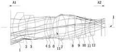
图1示出了实施例一中的光学成像镜头的光路图。FIG. 1 shows an optical path diagram of the optical imaging lens in the first embodiment.
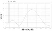
图2a示出了实施例一中的光学成像镜头在可见光(435nm~656nm)下的离焦曲线图。FIG. 2 a shows a defocus curve of the optical imaging lens in the first embodiment under visible light (435 nm˜656 nm).
图2b示出了实施例一中的光学成像镜头在红外光(850nm)下的离焦曲线图。Fig. 2b shows a defocus curve of the optical imaging lens in the first embodiment under infrared light (850 nm).
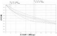
图3示出了实施例一中的光学成像镜头在可见光(435nm~656nm)下的MTF曲线图。FIG. 3 shows the MTF curve diagram of the optical imaging lens in the first embodiment under visible light (435 nm˜656 nm).
图4示出了实施例二中的光学成像镜头的光路图。FIG. 4 shows an optical path diagram of the optical imaging lens in the second embodiment.
图5a示出了实施例二中的光学成像镜头在可见光(435nm~656nm)下的离焦曲线图。Fig. 5a shows a defocus curve of the optical imaging lens in the second embodiment under visible light (435nm-656nm).
图5b示出了实施例二中的光学成像镜头在红外光(850nm)下的离焦曲线图。Fig. 5b shows a defocus curve of the optical imaging lens in the second embodiment under infrared light (850 nm).
图6示出了实施例二中的光学成像镜头在可见光(435nm~656nm)下的MTF曲线图。FIG. 6 shows the MTF graph of the optical imaging lens in the second embodiment under visible light (435 nm˜656 nm).
图7示出了实施例三中的光学成像镜头的光路图。FIG. 7 shows an optical path diagram of the optical imaging lens in the third embodiment.
图8a示出了实施例三中的光学成像镜头在可见光(435nm~656nm)下的离焦曲线图。FIG. 8 a shows a defocus curve of the optical imaging lens in the third embodiment under visible light (435 nm˜656 nm).
图8b示出了实施例三中的光学成像镜头在红外光(850nm)下的离焦曲线图。FIG. 8b shows a defocus curve of the optical imaging lens in Example 3 under infrared light (850 nm).
图9示出了实施例三中的光学成像镜头在可见光(435nm~656nm)下的MTF曲线图。FIG. 9 shows the MTF graph of the optical imaging lens in the third embodiment under visible light (435 nm˜656 nm).
图10示出了实施例四中的光学成像镜头的光路图。FIG. 10 shows an optical path diagram of the optical imaging lens in the fourth embodiment.
图11a示出了实施例四中的光学成像镜头在可见光(435nm~656nm)下的离焦曲线图。FIG. 11a shows a defocus curve of the optical imaging lens in the fourth embodiment under visible light (435 nm˜656 nm).
图11b示出了实施例四中的光学成像镜头在红外光(850nm)下的离焦曲线图。FIG. 11b shows a defocus curve of the optical imaging lens in the fourth embodiment under infrared light (850 nm).
图12示出了实施例四中的光学成像镜头在可见光(435nm~656nm)下的MTF曲线图。FIG. 12 shows the MTF curve diagram of the optical imaging lens in the fourth embodiment under visible light (435 nm˜656 nm).
图13示出了实施例一至实施例四中光学成像镜头的相关条件表达式的数值表格。FIG. 13 shows a numerical table of the relevant conditional expressions of the optical imaging lenses in the first to fourth embodiments.
具体实施方式Detailed ways
为进一步说明各实施例,本发明提供有附图。这些附图为本发明揭露内容的一部分,其主要用以说明实施例,并可配合说明书的相关描述来解释实施例的运作原理。配合参考这些内容,本领域普通技术人员应能理解其他可能的实施方式以及本发明的优点。图中的组件并未按比例绘制,而类似的组件符号通常用来表示类似的组件。To further illustrate the various embodiments, the present invention is provided with the accompanying drawings. These drawings are a part of the disclosure of the present invention, which are mainly used to illustrate the embodiments, and can be used in conjunction with the relevant description of the specification to explain the operation principles of the embodiments. With reference to these contents, one of ordinary skill in the art will understand other possible embodiments and advantages of the present invention. Components in the figures are not drawn to scale, and similar component symbols are often used to represent similar components.
现结合附图和具体实施方式对本发明进一步说明。The present invention will now be further described with reference to the accompanying drawings and specific embodiments.
在本说明书中所说的「一透镜具有正屈光率(或负屈光率)」,是指该透镜以高斯光学理论计算出来的近轴屈光率为正(或为负)。所说的「透镜的物侧面(或像侧面)」定义为成像光线通过透镜表面的特定范围。透镜的面形凹凸判断可依该领域中通常知识者的判断方式,即通过曲率半径(简写为R值)的正负号来判断透镜面形的凹凸。R值可常见被使用于光学设计软件中,例如Zemax或CodeV。R值亦常见于光学设计软件的透镜资料表(lens datasheet)中。以物侧面来说,当R值为正时,判定为物侧面为凸面;当R值为负时,判定物侧面为凹面。反之,以像侧面来说,当R值为正时,判定像侧面为凹面;当R值为负时,判定像侧面为凸面。In this specification, "a lens having a positive refractive power (or negative refractive power)" means that the paraxial refractive power of the lens calculated by Gaussian optics is positive (or negative). The so-called "object side (or image side) of the lens" is defined as the specific range of the imaging light passing through the surface of the lens. The surface concavity and convexity of the lens can be judged according to the judgment method of ordinary knowledge in the field, that is, the convexity and concavity of the lens surface shape can be judged by the sign of the radius of curvature (abbreviated as R value). R-values are commonly used in optical design software such as Zemax or CodeV. R-values are also commonly found in lens datasheets of optical design software. For the side of the object, when the value of R is positive, it is determined that the side of the object is convex; when the value of R is negative, the side of the object is determined to be concave. Conversely, for the image side, when the R value is positive, the image side is determined to be concave; when the R value is negative, the image side is determined to be convex.
本发明提供了一种光学成像镜头,其从物侧至像侧沿一光轴依次包括第一透镜至第十二透镜,该第一透镜至第十二透镜各自包括一朝向物侧且使成像光线通过的物侧面以及一朝向像侧且使成像光线通过的像侧面。The present invention provides an optical imaging lens, which sequentially includes a first lens to a twelfth lens along an optical axis from the object side to the image side, the first lens to the twelfth lens each include a The object side through which the light passes and an image side facing the image side and allowing the imaging light to pass through.
该光学成像镜头具有屈光率的透镜只有上述十二片,其中,The optical imaging lens has only the above-mentioned twelve lenses with refractive index, among which,
该第一透镜具有负屈光率,该第一透镜的物侧面为凸面,该第一透镜的像侧面为凹面;The first lens has a negative refractive index, the object side of the first lens is convex, and the image side of the first lens is concave;
该第二透镜具有负屈光率,该第二透镜的物侧面为凹面,该第二透镜的像侧面为凹面;The second lens has a negative refractive index, the object side of the second lens is concave, and the image side of the second lens is concave;
该第三透镜具有正屈光率,该第三透镜的物侧面为凸面,该第三透镜的像侧面为凸面;The third lens has a positive refractive index, the object side of the third lens is convex, and the image side of the third lens is convex;
该第四透镜具有负屈光率,该第四透镜的物侧面为凸面,该第四透镜的像侧面为凹面;The fourth lens has a negative refractive index, the object side of the fourth lens is convex, and the image side of the fourth lens is concave;
该第五透镜具有正屈光率,该第五透镜的物侧面为凸面,该第五透镜的像侧面为凹面或平面;The fifth lens has a positive refractive index, the object side of the fifth lens is convex, and the image side of the fifth lens is concave or plane;
该第六透镜具有负屈光率,该第六透镜的物侧面为凹面,该第六透镜的像侧面为凹面;The sixth lens has a negative refractive index, the object side of the sixth lens is concave, and the image side of the sixth lens is concave;
该第七透镜具有正屈光率,该第七透镜的物侧面为凸面,该第七透镜的像侧面为凸面;The seventh lens has a positive refractive index, the object side of the seventh lens is convex, and the image side of the seventh lens is convex;
该第八透镜具有正屈光率,该第八透镜的物侧面为凸面,该第八透镜的像侧面为凸面;The eighth lens has a positive refractive index, the object side of the eighth lens is convex, and the image side of the eighth lens is convex;
该第九透镜具有正屈光率,该第九透镜的物侧面为凸面,该第九透镜的像侧面为凸面;The ninth lens has a positive refractive index, the object side of the ninth lens is convex, and the image side of the ninth lens is convex;
该第十透镜具有负屈光率,该第十透镜的物侧面为凹面,该第十透镜的像侧面为凹面;The tenth lens has a negative refractive index, the object side of the tenth lens is concave, and the image side of the tenth lens is concave;
该第十一透镜具有负屈光率,该第十一透镜的物侧面为凸面,该第十一透镜的像侧面为凹面;The eleventh lens has a negative refractive index, the object side of the eleventh lens is convex, and the image side of the eleventh lens is concave;
该第十二透镜具有正屈光率,该第十二透镜的物侧面为凸面,该第十二透镜的像侧面为凹面。The twelfth lens has a positive refractive index, the object side of the twelfth lens is convex, and the image side of the twelfth lens is concave.
在一些实施例中,该光学成像镜头符合条件式:TTL≤95mm,BFL≥9mm,其中TTL为第一透镜物侧面到成像面在光轴上的距离,BFL为第十二透镜的像侧面到成像面在光轴上的距离,有利于提高成像质量。In some embodiments, the optical imaging lens satisfies the conditional formula: TTL≤95mm, BFL≥9mm, where TTL is the distance from the object side of the first lens to the imaging surface on the optical axis, and BFL is the distance from the image side of the twelfth lens to the The distance of the imaging plane on the optical axis is beneficial to improve the imaging quality.
在一些实施例中,该光学成像镜头符合条件式:0.55≤ALT/TTL≤0.7,其中ALT为该光学成像系统在光轴上的厚度总和,TTL为第一透镜物侧面到成像面在光轴上的距离,有利于提高成像质量。In some embodiments, the optical imaging lens satisfies the conditional formula: 0.55≤ALT/TTL≤0.7, where ALT is the sum of the thicknesses of the optical imaging system on the optical axis, and TTL is the optical axis from the object side of the first lens to the imaging surface. The distance above is beneficial to improve the image quality.
在一些实施例中,该光学成像镜头符合条件式:2.0≤ALT/ALG≤3.5,其中,ALT为该光学成像系统在光轴上的厚度总和,ALG为该光学成像系统在光轴上的空气间隙总和,有利于提高成像质量。In some embodiments, the optical imaging lens satisfies the conditional formula: 2.0≤ALT/ALG≤3.5, where ALT is the sum of the thicknesses of the optical imaging system on the optical axis, and ALG is the air of the optical imaging system on the optical axis The sum of the gaps is beneficial to improve the imaging quality.
在一些实施例中,该光学成像镜头符合条件式:vd7=vd8,且vd7≥80,vd8≥80,其中vd7为第七透镜的色散系数,vd8为第八透镜的色散系数;该第七透镜和第八透镜采用低色散系数的透镜来矫正系统色差,实现可见光和红外光共焦,可实现日夜两用。In some embodiments, the optical imaging lens satisfies the conditional formula: vd7=vd8, and vd7≥80, vd8≥80, wherein vd7 is the dispersion coefficient of the seventh lens, and vd8 is the dispersion coefficient of the eighth lens; the seventh lens And the eighth lens adopts a lens with low dispersion coefficient to correct the system chromatic aberration, realize the confocal of visible light and infrared light, and can realize both day and night.
在一些实施例中,第二透镜和第三透镜胶合组成胶合镜片,第四透镜和第五透镜胶合组成胶合镜片,以减少轴、面偏敏感度。In some embodiments, the second lens and the third lens are cemented to form a cemented lens, and the fourth lens and the fifth lens are cemented to form a cemented lens, so as to reduce the sensitivity of axial and surface polarization.
在一些实施例中,第九透镜和第十透镜胶合组成胶合镜片,且符合下列条件式:vd9-vd10≥20,其中Vd9为第九透镜的色散系数,Vd10为第十透镜的色散系数。该胶合镜片采用高低色散材料结合,有利于消除系统色差,优化红外成像表现。In some embodiments, the ninth lens and the tenth lens are cemented to form a cemented lens, and meet the following conditional formula: vd9-vd10≥20, where Vd9 is the dispersion coefficient of the ninth lens, and Vd10 is the dispersion coefficient of the tenth lens. The cemented lens adopts a combination of high and low dispersion materials, which is conducive to eliminating system chromatic aberration and optimizing infrared imaging performance.
在一些实施例中,该光学成像镜头符合条件式:vd12-vd11≥20,其中Vd11为第十一透镜的色散系数,Vd12为第十二透镜的色散系数。第十一透镜和第十二透镜采用高低色散材料结合,有利于消除系统色差,优化红外成像表现。In some embodiments, the optical imaging lens satisfies the conditional formula: vd12-vd11≥20, wherein Vd11 is the dispersion coefficient of the eleventh lens, and Vd12 is the dispersion coefficient of the twelfth lens. The eleventh lens and the twelfth lens are combined with high and low dispersion materials, which is conducive to eliminating system chromatic aberration and optimizing infrared imaging performance.
实施例一Example 1
本具体实施例提供了一种光学成像镜头,参考图1,其从物侧A1至像侧A2沿一光轴I依次包括第一透镜至第十二透镜,该第一透镜至第十二透镜各自包括一朝向物侧且使成像光线通过的物侧面以及一朝向像侧且使成像光线通过的像侧面;其中,This specific embodiment provides an optical imaging lens. Referring to FIG. 1 , it includes a first lens to a twelfth lens in order from the object side A1 to the image side A2 along an optical axis I, and the first lens to the twelfth lens Each includes an object side facing the object side and passing the imaging light and an image side facing the image side and allowing the imaging light to pass; wherein,
该第一透镜1具有负屈光率,该第一透镜1的物侧面为凸面,该第一透镜1的像侧面为凹面;The
该第二透镜2具有负屈光率,该第二透镜2的物侧面为凹面,该第二透镜2的像侧面为凹面;The
该第三透镜3具有正屈光率,该第三透镜3的物侧面为凸面,该第三透镜3的像侧面为凸面;The
该第四透镜4具有负屈光率,该第四透镜4的物侧面为凸面,该第四透镜4的像侧面为凹面;The
该第五透镜5具有正屈光率,该第五透镜5的物侧面为凸面,该第五透镜5的像侧面为凹面;The
该第六透镜6具有负屈光率,该第六透镜6的物侧面为凹面,该第六透镜6的像侧面为凹面;The
该第七透镜7具有正屈光率,该第七透镜7的物侧面为凸面,该第七透镜7的像侧面为凸面;The
该第八透镜8具有正屈光率,该第八透镜8的物侧面为凸面,该第八透镜8的像侧面为凸面;The
该第九透镜9具有正屈光率,该第九透镜9的物侧面为凸面,该第九透镜9的像侧面为凸面;The
该第十透镜10具有负屈光率,该第十透镜10的物侧面为凹面,该第十透镜10的像侧面为凹面;The
该第十一透镜11具有负屈光率,该第十一透镜11的物侧面为凸面,该第十一透镜11的像侧面为凹面;The
该第十二透镜12具有正屈光率,该第十二透镜12的物侧面为凸面,该第十二透镜12的像侧面为凹面。The
该光学成像镜头具有屈光率的透镜只有上述十二片,且第一透镜至第十二透镜的物侧面和像侧面均为球面;其中,第二、第三透镜胶合组成胶合透镜,第四、第五透镜胶合组成胶合透镜,第九、第十透镜胶合组成胶合透镜,光阑13位于第六透镜和第七透镜之间。The optical imaging lens has only the above twelve lenses with refractive power, and the object side and the image side of the first lens to the twelfth lens are spherical; wherein, the second and third lenses are cemented to form a cemented lens, and the fourth lens The fifth lens is cemented to form a cemented lens, the ninth and tenth lenses are cemented to form a cemented lens, and the
本具体实施例的详细光学数据如表1所示。The detailed optical data of this specific example is shown in Table 1.
表1.实施例一详细光学数据:Table 1. Detailed optical data of Example 1:

本具体实施例中镜头焦距为f=25mm,光圈值为FNO=1.4,成像面=Φ17.6mm,镜头总长=93mm。其它相关条件表达式的数值请参考图13。图13中,In this specific embodiment, the focal length of the lens is f=25mm, the aperture value is FNO=1.4, the imaging surface=Φ17.6mm, and the total length of the lens=93mm. Please refer to Figure 13 for the values of other related conditional expressions. In Figure 13,
T1至T12分别为第一至第十二透镜在光轴上的中心厚度;T1 to T12 are the central thicknesses of the first to twelfth lenses on the optical axis, respectively;
G12为第一透镜的像侧面到第二透镜的物侧面在光轴上的空气间隙;G12 is the air gap on the optical axis from the image side of the first lens to the object side of the second lens;
G23为第二透镜的像侧面到第三透镜的物侧面在光轴上的空气间隙;G23 is the air gap on the optical axis from the image side of the second lens to the object side of the third lens;
G34为第三透镜的像侧面到第四透镜的物侧面在光轴上的空气间隙;G34 is the air gap on the optical axis from the image side of the third lens to the object side of the fourth lens;
G45为第四透镜的像侧面到第五透镜的物侧面在光轴上的空气间隙;G45 is the air gap between the image side of the fourth lens and the object side of the fifth lens on the optical axis;
G56为第五透镜的像侧面到第六透镜的物侧面在光轴上的空气间隙;G56 is the air gap on the optical axis from the image side of the fifth lens to the object side of the sixth lens;
G67为第六透镜的像侧面到第七透镜的物侧面在光轴上的空气间隙;G67 is the air gap on the optical axis from the image side of the sixth lens to the object side of the seventh lens;
G78为第七透镜的像侧面到第八透镜的物侧面在光轴上的空气间隙;G78 is the air gap on the optical axis from the image side of the seventh lens to the object side of the eighth lens;
G89为第八透镜的像侧面到第九透镜的物侧面在光轴上的空气间隙;G89 is the air gap on the optical axis from the image side of the eighth lens to the object side of the ninth lens;
G910为第九透镜的像侧面到第十透镜的物侧面在光轴上的空气间隙;G910 is the air gap on the optical axis from the image side of the ninth lens to the object side of the tenth lens;
G1011为第十透镜的像侧面到第十一透镜的物侧面在光轴上的空气间隙;G1011 is the air gap on the optical axis from the image side of the tenth lens to the object side of the eleventh lens;
G1112为第十一透镜的像侧面到第十二透镜的物侧面在光轴上的空气间隙;G1112 is the air gap on the optical axis from the image side of the eleventh lens to the object side of the twelfth lens;
Gstop为光阑前后空气间隙总和;Gstop is the sum of the air gaps before and after the diaphragm;
ALT为透镜在光轴上的厚度总和;ALT is the sum of the thickness of the lens on the optical axis;
ALG为系统空气间隙之和;ALG is the sum of the system air gaps;
TTL为第一透镜到该成像面在光轴上的距离。TTL is the distance from the first lens to the imaging surface on the optical axis.
本具体实施例的光路图请参阅图1。可见光(435nm~656nm)的离焦曲线图请参阅图2a,红外光(850nm)的离焦曲线图请参阅图2b,从图2a和图2b中可以得出该款镜头在可见光和红外光的离焦量小于10μm,具有共焦功能,可实现日夜两用。可见光(435nm~656nm)的MTF曲线图请参阅图3,从图中可以该款镜头在使用时满足空间频率达140lp/m,镜头成像面大小可满足1.1英寸和12M以上的画质的需求。Please refer to FIG. 1 for an optical path diagram of this specific embodiment. Please refer to Figure 2a for the defocus curve of visible light (435nm ~ 656nm) and Figure 2b for the defocus curve of infrared light (850nm). The defocus amount is less than 10μm, and it has the confocal function, which can be used for both day and night. Please refer to Figure 3 for the MTF curve of visible light (435nm ~ 656nm). From the figure, it can be seen that the lens can meet the spatial frequency of 140lp/m when in use, and the imaging surface size of the lens can meet the needs of image quality above 1.1 inches and 12M.
实施例二
本实施例与实施例一的各个透镜的面型凹凸和屈光率相同,仅各透镜表面的曲率半径、透镜厚度等光学参数不同。The surface concavo-convex and refractive index of each lens in this embodiment and the first embodiment are the same, and only the optical parameters such as the radius of curvature of the surface of each lens and the thickness of the lens are different.
本具体实施例的详细光学数据如表2所示。The detailed optical data of this specific example are shown in Table 2.
表2.实施例二的详细光学数据:Table 2. Detailed Optical Data of Example Two:

本具体实施例中镜头焦距为f=24.5mm,光圈值为FNO=1.45,成像面=Φ17.6mm,镜头总长=93.5mm。其它相关条件表达式的数值请参考图13。In this specific embodiment, the focal length of the lens is f=24.5mm, the aperture value is FNO=1.45, the imaging surface=Φ17.6mm, and the total length of the lens=93.5mm. Please refer to Figure 13 for the values of other related conditional expressions.
本具体实施例的光路图请参阅图4。可见光(435nm~656nm)的离焦曲线图请参阅图5a,红外光(850nm)的离焦曲线图请参阅图5b,从图5a和图5b中可以得出该款镜头在可见光和红外光的离焦量小于10μm,具有共焦功能,可实现日夜两用。可见光(435nm~656nm)的MTF曲线图请参阅图6,从图中可以该款镜头在使用时满足空间频率达140lp/m,镜头成像面大小可满足1.1英寸和12M以上的画质的需求。Please refer to FIG. 4 for an optical path diagram of this specific embodiment. Please refer to Figure 5a for the defocus curve of visible light (435nm ~ 656nm), and Figure 5b for the defocus curve of infrared light (850nm). The defocus amount is less than 10μm, and it has the confocal function, which can be used for both day and night. Please refer to Figure 6 for the MTF curve of visible light (435nm ~ 656nm). From the figure, it can be seen that the lens can meet the spatial frequency of 140lp/m when in use, and the imaging surface size of the lens can meet the needs of image quality above 1.1 inches and 12M.
实施例三
本实施例与实施例一的各个透镜的面型凹凸和屈光率相同,仅各透镜表面的曲率半径、透镜厚度等光学参数不同。The surface concavo-convex and refractive index of each lens in this embodiment and the first embodiment are the same, and only the optical parameters such as the radius of curvature of the surface of each lens and the thickness of the lens are different.
本具体实施例的详细光学数据如表3所示。The detailed optical data of this specific example are shown in Table 3.
表3.实施例三的详细光学数据:Table 3. Detailed Optical Data of Example Three:

本具体实施例中镜头焦距为f=24.8mm,光圈值为FNO=1.4,成像面=Φ17.8mm,镜头总长=92.6mm。其它相关条件表达式的数值请参考图13。In this specific embodiment, the focal length of the lens is f=24.8mm, the aperture value is FNO=1.4, the imaging surface=Φ17.8mm, and the total length of the lens=92.6mm. Please refer to Figure 13 for the values of other related conditional expressions.
本具体实施例的光路图请参阅图7。可见光(435nm~656nm)的离焦曲线图请参阅图8a,红外光(850nm)的离焦曲线图请参阅图8b,从图8a和图8b中可以得出该款镜头在可见光和红外光的离焦量小于10μm,具有共焦功能,可实现日夜两用。可见光(435nm~656nm)的MTF曲线图请参阅图9,从图中可以该款镜头在使用时满足空间频率达140lp/m,镜头成像面大小可满足1.1英寸和12M以上的画质的需求。Please refer to FIG. 7 for an optical path diagram of this specific embodiment. Please refer to Figure 8a for the defocus curve of visible light (435nm ~ 656nm), and Figure 8b for the defocus curve of infrared light (850nm). The defocus amount is less than 10μm, and it has the confocal function, which can be used for both day and night. Please refer to Figure 9 for the MTF curve of visible light (435nm~656nm). From the figure, it can be seen that the lens can meet the spatial frequency of 140lp/m when in use, and the imaging surface size of the lens can meet the needs of image quality above 1.1 inches and 12M.
实施例四
本实施例与实施例一的各个透镜的面型凹凸和屈光率相同,仅各透镜表面的曲率半径、透镜厚度等光学参数不同。The surface concavo-convex and refractive index of each lens in this embodiment and the first embodiment are the same, and only the optical parameters such as the radius of curvature of the surface of each lens and the thickness of the lens are different.
本具体实施例的详细光学数据如表4所示。The detailed optical data of this specific example are shown in Table 4.
表3.实施例四的详细光学数据:Table 3. Detailed Optical Data of Example Four:

本具体实施例中镜头焦距为f=24.5mm,光圈值为FNO=1.4,成像面=Φ17.6mm,镜头总长=90.7mm。其它相关条件表达式的数值请参考图13。In this specific embodiment, the focal length of the lens is f=24.5mm, the aperture value is FNO=1.4, the imaging surface=Φ17.6mm, and the total length of the lens=90.7mm. Please refer to Figure 13 for the values of other related conditional expressions.
本具体实施例的光路图请参阅图10。可见光(435nm~656nm)的离焦曲线图请参阅图11a,红外光(850nm)的离焦曲线图请参阅图11b,从图11a和图11b中可以得出该款镜头在可见光和红外光的离焦量小于10μm,具有共焦功能,可实现日夜两用。可见光(435nm~656nm)的MTF曲线图请参阅图12,从图中可以该款镜头在使用时满足空间频率达140lp/m,镜头成像面大小可满足1.1英寸和12M以上的画质的需求。Please refer to FIG. 10 for an optical path diagram of this specific embodiment. Please refer to Figure 11a for the defocus curve of visible light (435nm ~ 656nm) and Figure 11b for the defocus curve of infrared light (850nm). The defocus amount is less than 10μm, and it has the confocal function, which can be used for both day and night. Please refer to Figure 12 for the MTF curve of visible light (435nm ~ 656nm). From the figure, it can be seen that the lens can meet the spatial frequency of 140lp/m when in use, and the imaging surface size of the lens can meet the needs of image quality above 1.1 inches and 12M.
尽管结合优选实施方案具体展示和介绍了本发明,但所属领域的技术人员应该明白,在不脱离所附权利要求书所限定的本发明的精神和范围内,在形式上和细节上可以对本发明做出各种变化,均为本发明的保护范围。Although the present invention has been particularly shown and described in connection with preferred embodiments, it will be understood by those skilled in the art that changes in form and detail may be made to the present invention without departing from the spirit and scope of the invention as defined by the appended claims. Various changes are made within the protection scope of the present invention.
Claims (9)
Translated fromChinesePriority Applications (1)
| Application Number | Priority Date | Filing Date | Title |
|---|---|---|---|
| CN202010057670.2ACN111158108B (en) | 2020-01-19 | 2020-01-19 | An optical imaging lens |
Applications Claiming Priority (1)
| Application Number | Priority Date | Filing Date | Title |
|---|---|---|---|
| CN202010057670.2ACN111158108B (en) | 2020-01-19 | 2020-01-19 | An optical imaging lens |
Publications (2)
| Publication Number | Publication Date |
|---|---|
| CN111158108Atrue CN111158108A (en) | 2020-05-15 |
| CN111158108B CN111158108B (en) | 2024-07-23 |
Family
ID=70564048
Family Applications (1)
| Application Number | Title | Priority Date | Filing Date |
|---|---|---|---|
| CN202010057670.2AActiveCN111158108B (en) | 2020-01-19 | 2020-01-19 | An optical imaging lens |
Country Status (1)
| Country | Link |
|---|---|
| CN (1) | CN111158108B (en) |
Cited By (2)
| Publication number | Priority date | Publication date | Assignee | Title |
|---|---|---|---|---|
| CN111722381A (en)* | 2020-07-24 | 2020-09-29 | 东莞市宇瞳光学科技股份有限公司 | a visual lens |
| CN115185062A (en)* | 2021-12-20 | 2022-10-14 | 福建福光股份有限公司 | High-pixel compact type large-picture optical lens |
Citations (5)
| Publication number | Priority date | Publication date | Assignee | Title |
|---|---|---|---|---|
| US20070014025A1 (en)* | 2005-04-22 | 2007-01-18 | Canon Kabushiki Kaisha | Optical system |
| CN103135207A (en)* | 2012-11-15 | 2013-06-05 | 玉晶光电(厦门)有限公司 | Portable electronic device and optical imaging lens thereof |
| US20130250166A1 (en)* | 2012-03-20 | 2013-09-26 | Microsoft Corporation | High-Speed Wide-Angle Lens Construction |
| CN209542921U (en)* | 2018-09-21 | 2019-10-25 | 先进光电科技股份有限公司 | Optical Imaging Module |
| CN211149042U (en)* | 2020-01-19 | 2020-07-31 | 厦门力鼎光电股份有限公司 | Optical imaging lens |
- 2020
- 2020-01-19CNCN202010057670.2Apatent/CN111158108B/enactiveActive
Patent Citations (5)
| Publication number | Priority date | Publication date | Assignee | Title |
|---|---|---|---|---|
| US20070014025A1 (en)* | 2005-04-22 | 2007-01-18 | Canon Kabushiki Kaisha | Optical system |
| US20130250166A1 (en)* | 2012-03-20 | 2013-09-26 | Microsoft Corporation | High-Speed Wide-Angle Lens Construction |
| CN103135207A (en)* | 2012-11-15 | 2013-06-05 | 玉晶光电(厦门)有限公司 | Portable electronic device and optical imaging lens thereof |
| CN209542921U (en)* | 2018-09-21 | 2019-10-25 | 先进光电科技股份有限公司 | Optical Imaging Module |
| CN211149042U (en)* | 2020-01-19 | 2020-07-31 | 厦门力鼎光电股份有限公司 | Optical imaging lens |
Cited By (3)
| Publication number | Priority date | Publication date | Assignee | Title |
|---|---|---|---|---|
| CN111722381A (en)* | 2020-07-24 | 2020-09-29 | 东莞市宇瞳光学科技股份有限公司 | a visual lens |
| CN115185062A (en)* | 2021-12-20 | 2022-10-14 | 福建福光股份有限公司 | High-pixel compact type large-picture optical lens |
| CN115185062B (en)* | 2021-12-20 | 2024-01-12 | 福建福光股份有限公司 | High-pixel compact large-picture optical lens |
Also Published As
| Publication number | Publication date |
|---|---|
| CN111158108B (en) | 2024-07-23 |
Similar Documents
| Publication | Publication Date | Title |
|---|---|---|
| CN109799597B (en) | Optical imaging lens | |
| CN110361833A (en) | A kind of optical imaging lens | |
| CN110780431B (en) | Zoom lens | |
| CN110456486A (en) | An optical imaging lens | |
| CN211603698U (en) | Large-light-transmission low-distortion optical imaging lens | |
| CN113419325B (en) | Optical imaging lens with liquid lens | |
| CN211955960U (en) | Optical imaging lens with fixed focus and low chromatic aberration | |
| CN209707794U (en) | An optical imaging lens | |
| CN111158108B (en) | An optical imaging lens | |
| CN111722378A (en) | A fisheye lens with large image area and high resolution | |
| CN111983788A (en) | Wide-angle lens | |
| CN213482550U (en) | Wide-angle optical imaging lens | |
| CN211180372U (en) | an optical imaging lens | |
| CN211014818U (en) | Zoom lens | |
| CN111239966B (en) | Optical imaging lens | |
| CN209842205U (en) | An optical imaging lens | |
| CN209765145U (en) | optical imaging lens | |
| CN211149042U (en) | Optical imaging lens | |
| CN209496194U (en) | An optical imaging lens | |
| CN218471037U (en) | A Datong light high-resolution telephoto lens | |
| CN111103674A (en) | Optical imaging lens | |
| CN214846005U (en) | Optical imaging lens | |
| CN211180370U (en) | Optical imaging lens | |
| CN211149041U (en) | an optical imaging lens | |
| CN213780515U (en) | Optical imaging lens and panoramic lens |
Legal Events
| Date | Code | Title | Description |
|---|---|---|---|
| PB01 | Publication | ||
| PB01 | Publication | ||
| SE01 | Entry into force of request for substantive examination | ||
| SE01 | Entry into force of request for substantive examination | ||
| GR01 | Patent grant | ||
| GR01 | Patent grant |