CN111145296B - A method of drawing vector map line symbol circular arrows considering the consistency of line width - Google Patents
A method of drawing vector map line symbol circular arrows considering the consistency of line widthDownload PDFInfo
- Publication number
- CN111145296B CN111145296BCN201911363753.8ACN201911363753ACN111145296BCN 111145296 BCN111145296 BCN 111145296BCN 201911363753 ACN201911363753 ACN 201911363753ACN 111145296 BCN111145296 BCN 111145296B
- Authority
- CN
- China
- Prior art keywords
- value
- line
- line width
- vector
- points
- Prior art date
- Legal status (The legal status is an assumption and is not a legal conclusion. Google has not performed a legal analysis and makes no representation as to the accuracy of the status listed.)
- Active
Links
Images

Classifications
- G—PHYSICS
- G06—COMPUTING OR CALCULATING; COUNTING
- G06T—IMAGE DATA PROCESSING OR GENERATION, IN GENERAL
- G06T11/00—2D [Two Dimensional] image generation
- G06T11/20—Drawing from basic elements, e.g. lines or circles
- G06T11/203—Drawing of straight lines or curves
- G—PHYSICS
- G06—COMPUTING OR CALCULATING; COUNTING
- G06T—IMAGE DATA PROCESSING OR GENERATION, IN GENERAL
- G06T11/00—2D [Two Dimensional] image generation
- G06T11/001—Texturing; Colouring; Generation of texture or colour
- G—PHYSICS
- G09—EDUCATION; CRYPTOGRAPHY; DISPLAY; ADVERTISING; SEALS
- G09B—EDUCATIONAL OR DEMONSTRATION APPLIANCES; APPLIANCES FOR TEACHING, OR COMMUNICATING WITH, THE BLIND, DEAF OR MUTE; MODELS; PLANETARIA; GLOBES; MAPS; DIAGRAMS
- G09B29/00—Maps; Plans; Charts; Diagrams, e.g. route diagram
- G09B29/003—Maps
- G09B29/006—Representation of non-cartographic information on maps, e.g. population distribution, wind direction, radiation levels, air and sea routes
- Y—GENERAL TAGGING OF NEW TECHNOLOGICAL DEVELOPMENTS; GENERAL TAGGING OF CROSS-SECTIONAL TECHNOLOGIES SPANNING OVER SEVERAL SECTIONS OF THE IPC; TECHNICAL SUBJECTS COVERED BY FORMER USPC CROSS-REFERENCE ART COLLECTIONS [XRACs] AND DIGESTS
- Y02—TECHNOLOGIES OR APPLICATIONS FOR MITIGATION OR ADAPTATION AGAINST CLIMATE CHANGE
- Y02D—CLIMATE CHANGE MITIGATION TECHNOLOGIES IN INFORMATION AND COMMUNICATION TECHNOLOGIES [ICT], I.E. INFORMATION AND COMMUNICATION TECHNOLOGIES AIMING AT THE REDUCTION OF THEIR OWN ENERGY USE
- Y02D10/00—Energy efficient computing, e.g. low power processors, power management or thermal management
Landscapes
- Engineering & Computer Science (AREA)
- Physics & Mathematics (AREA)
- Theoretical Computer Science (AREA)
- General Physics & Mathematics (AREA)
- Life Sciences & Earth Sciences (AREA)
- Ecology (AREA)
- Mathematical Physics (AREA)
- Business, Economics & Management (AREA)
- Educational Administration (AREA)
- Educational Technology (AREA)
- Image Generation (AREA)
Abstract
Translated fromChinese
Description
Translated fromChinese技术领域Technical Field
本发明涉及数字地图制图领域和地理信息系统领域的矢量地图线符号圆形箭头绘制方法,尤其涉及一种顾及线宽一致性的矢量地图线符号圆形箭头绘制方法。The invention relates to a method for drawing circular arrows of vector map line symbols in the field of digital map making and geographic information system, and in particular to a method for drawing circular arrows of vector map line symbols taking into account line width consistency.
背景技术Background Art
数字地图制图是将现实世界中各种空间信息以地图的方式呈现出来,点、线和面要素是地图中最基础的三种表达结构,由此主导了点、线和面符号化方法。通过各种不同的点符号、线符号和面符号,能够将空间实体的分布状况、关联关系、相互作用等信息形象化的传递给读图者。为了能够支撑读图者快速理解地图、准确获取空间信息,地图符号的绘制是最为关键的因素。在现实地理世界中,广泛存在着“方向”型的空间信息,如风吹的方向、河流的方向、道路的行驶方向等。为了能够将此类方向型的信息传递给读图者,带有圆形箭头的线符号是一种常用的方法。Digital mapping is to present various spatial information in the real world in the form of maps. Points, lines and surface elements are the three most basic expression structures in maps, which dominate the point, line and surface symbolization methods. Through various point symbols, line symbols and surface symbols, the distribution status, associations, interactions and other information of spatial entities can be conveyed to the map reader in a visual way. In order to support the map reader to quickly understand the map and accurately obtain spatial information, the drawing of map symbols is the most critical factor. In the real geographical world, there is a wide range of "directional" spatial information, such as the direction of the wind, the direction of the river, the direction of the road, etc. In order to convey this kind of directional information to the map reader, a line symbol with a circular arrow is a common method.
为了能够绘制带有圆形箭头的线符号,当前主要有两种方法:一种是基于软件绘制的方法,一种是基于GPU硬件的方法。前者广泛应用于现有各种二维地图平台上,主要是通过纯软件的方式来操作像素着色,典型的方法有GDI+,Cairo,AGG等。例如,论文《面向GIS的矢量线状符号填充算法研究》(张海泉,潘懋,吴焕萍,等.《地理与地理信息科学》,2004,20(04):11-14.),给出了一种基于GDI+的纯软件绘制方法来表达矢量线要素。该种方法严格依赖于矢量线的屏幕坐标和屏幕宽度,当地图缩放时,需要不断的进行重新计算和绘制,严重降低了地图显示的效率。针对此效率低下的问题,后续的研究大多数集中于如何用硬件加速的方法,即后者基于GPU硬件的方法来实现矢量线符号的绘制。In order to draw line symbols with circular arrows, there are currently two main methods: one is a software-based method and the other is a GPU-based method. The former is widely used on various existing two-dimensional map platforms, mainly operating pixel shading in a pure software manner. Typical methods include GDI+, Cairo, AGG, etc. For example, the paper "Research on Vector Line Symbol Filling Algorithm for GIS" (Zhang Haiquan, Pan Mao, Wu Huanping, et al. "Geography and Geographic Information Science", 2004, 20(04):11-14.) gives a pure software drawing method based on GDI+ to express vector line features. This method strictly depends on the screen coordinates and screen width of the vector line. When the map is scaled, it needs to be recalculated and drawn continuously, which seriously reduces the efficiency of map display. In response to this inefficiency problem, most subsequent studies focus on how to use hardware acceleration methods, that is, the latter GPU-based methods to achieve the drawing of vector line symbols.
基于GPU硬件绘制的方法主要是研究如何通过GPU着色器(Shader)来绘制线符号。代表性的方法如论文《A function-based linear map symbol building and renderingmethod using shader language》(Yue SS,Yang JS,Chen M,等.《International Journalof Geographical Information Science》,2016,30(2):143-16)提出了一种利用OpenGLShader来构建线符号并用GPU绘制。该方法依赖于一个颜色二维数组来表达符号结构,虽然能够通过数组标记来表达和绘制虚线符号,但整个方法中只是针对固定地图比例尺的绘制,对于线宽的一致性问题完全没有涉及;此论文方法也只是对不带箭头的线符号,如何处理带圆形箭头的线符号未有涉及。The method based on GPU hardware drawing mainly studies how to draw line symbols through GPU shaders. Representative methods such as the paper "A function-based linear map symbol building and rendering method using shader language" (Yue SS, Yang JS, Chen M, et al. "International Journal of Geographical Information Science", 2016, 30 (2): 143-16) proposed a method of using OpenGL Shader to build line symbols and draw them with GPU. This method relies on a two-dimensional array of colors to express the symbol structure. Although it is possible to express and draw dashed line symbols through array markers, the entire method is only for drawing fixed map scales, and the consistency of line width is not involved at all; this paper method is only for line symbols without arrows, and how to deal with line symbols with circular arrows is not involved.
而论文《一种基于屏幕的三维地图线状符号渲染方法》(刘君妍,陈雅茜,高亦远,等.《地球信息科学学报》,2018,20(8):1047-1054)提出了将矢量线要素映射成为纹理数据,通过纹理数据来绘制线;该方法主要是针对线要素与地形的融合,线要素的线宽处理明确是随着地图缩放而变化的。此外名称为“基于GPU的地图线形符号绘制方法及系统”(申请号201310125110.6)的中国专利,名为“基于GPU的宽度渐变线型地图符号绘制方法”(申请号201610015703.0)的中国专利,名为“基于GPU的颜色渐变线型地图符号绘制方法”(申请号201610016561.X),都是在分析GPU绘制矢量线要素难点的基础上,提出了用Shader着色器来绘制线符号的方法。但是这些方法都是针对固定比例尺的线符号绘制,当地图比例尺变化时,为了保持线宽不变,前述方法都需要重新三角化和绘制。反复不断的三角化对绘制效率具有明显的影响,由此造成了地图的缩放交互仍然存在效率瓶颈。并且由于圆形箭头的特殊性,已有GPU硬件绘制方法均未提出明确的解决方案。The paper "A Screen-based 3D Map Linear Symbol Rendering Method" (Liu Junyan, Chen Yaqian, Gao Yiyuan, et al. Journal of Geo-Information Science, 2018, 20(8): 1047-1054) proposed mapping vector line elements into texture data and drawing lines through texture data; this method is mainly aimed at the fusion of line elements and terrain, and the line width processing of line elements is clearly changed with the zoom of the map. In addition, the Chinese patent named "GPU-based Map Linear Symbol Drawing Method and System" (application number 201310125110.6), the Chinese patent named "GPU-based Width Gradient Linear Map Symbol Drawing Method" (application number 201610015703.0), and the Chinese patent named "GPU-based Color Gradient Linear Map Symbol Drawing Method" (application number 201610016561.X) all proposed methods of using Shader shaders to draw line symbols based on the analysis of the difficulties of GPU drawing vector line elements. However, these methods are all for drawing line symbols at a fixed scale. When the map scale changes, in order to keep the line width unchanged, the above methods need to be re-triangulated and re-drawn. Repeated triangulation has a significant impact on drawing efficiency, which results in the efficiency bottleneck of map zoom interaction. And due to the particularity of circular arrows, existing GPU hardware drawing methods have not proposed a clear solution.
整体而言,现有方法主要是面向静态线宽绘制,当地图比例尺缩放时,需要重新计算和绘制;另外,基于GPU硬件加速的带圆形箭头的线要素绘制也未见公开方法。本发明提出了一种顾及线宽一致性的矢量地图线要素圆形箭头绘制方法,其可以实现:(1)随着地图比例尺缩放保持线宽一致,(2)矢量线要素不需要重新进行三角化,(3)圆形箭头能够与线要素一起绘制。因为GPU的绘制依赖于三角面片,当一个矢量线被三角化成三角形序列后,GPU只能拿到坐标和颜色,整个绘制是无状态的(即无法区分哪里是起始点、哪里是终止点、哪里是箭头等)。为了能够在GPU中绘制圆形箭头,本发明的核心就是构建了独特的GPU状态协议,从而驱动CPU-GPU协同工作,实现随着地图缩放线宽保持一致的圆形箭头绘制。In general, existing methods are mainly aimed at drawing static line widths, and when the map scale is scaled, recalculation and drawing are required; in addition, there is no public method for drawing line elements with circular arrows based on GPU hardware acceleration. The present invention proposes a method for drawing circular arrows for vector map line elements that takes into account line width consistency, which can achieve: (1) keeping the line width consistent as the map scale is scaled, (2) vector line elements do not need to be re-triangulated, and (3) circular arrows can be drawn together with line elements. Because GPU drawing relies on triangular facets, when a vector line is triangulated into a triangle sequence, the GPU can only get the coordinates and colors, and the entire drawing is stateless (i.e., it is impossible to distinguish where the starting point is, where the end point is, where the arrow is, etc.). In order to be able to draw circular arrows in the GPU, the core of the present invention is to construct a unique GPU state protocol, thereby driving the CPU-GPU to work together to achieve the drawing of circular arrows with consistent line width as the map is scaled.
发明内容Summary of the invention
本发明的目的是在GPU绘制环境下,针对带有圆形箭头的地图线符号线宽一致性绘制需求,提供一种能够实现在地图缩放过程中不改变线宽、不重新三角化,实现线要素起点、终点处的圆形箭头绘制的顾及线宽一致性的矢量地图线符号圆形箭头绘制方法。The purpose of the present invention is to provide a vector map line symbol circular arrow drawing method that takes into account line width consistency and can achieve the drawing of circular arrows at the starting point and end point of line elements without changing the line width or re-triangulation during map zooming in a GPU drawing environment, in response to the line width consistency drawing requirements of map line symbols with circular arrows.
技术方案:一种顾及线宽一致性的矢量地图线符号圆形箭头绘制方法,包括下列步骤:Technical solution: A method for drawing circular arrows of vector map line symbols taking into account line width consistency, comprising the following steps:
步骤1、对矢量线要素的坐标序列进行初始化,设置以像素为单位的屏幕线宽,设置起点和终点处是否绘制圆形箭头;
步骤2、构建矢量线要素的世界坐标系和屏幕坐标系之间的转换规则,通过此规则将屏幕线宽转换为世界坐标系的线宽,根据此世界坐标系线宽:顺序遍历矢量线要素的每个坐标,由线生成三角形集合,其中每个三角形的每个顶点都具有沿线走向的U值和垂直线走向的V值,并且每个顶点还具有一个缩放方向向量D值;对矢量线要素的起点和终点分别进行膨胀操作和协议标记;Step 2, construct the conversion rule between the world coordinate system and the screen coordinate system of the vector line element, and convert the screen line width into the line width of the world coordinate system through this rule. According to the line width of the world coordinate system: traverse each coordinate of the vector line element sequentially, and generate a triangle set from the line, where each vertex of each triangle has a U value along the line and a V value perpendicular to the line, and each vertex also has a scaling direction vector D value; perform expansion operation and protocol marking on the starting point and end point of the vector line element respectively;
步骤3、组装GPU着色器的状态协议:该状态协议包括两个层次,一个是顶点层,包括U值、V值、缩放方向D值,另一个是结构层,包括最大线宽M值、地图比例缩放S值、起点标记CB、终点标记CE;Step 3: Assemble the state protocol of GPU shader: The state protocol includes two levels, one is the vertex layer, including U value, V value, and scaling direction D value, and the other is the structure layer, including the maximum line width M value, map scale S value, starting point mark CB, and end point mark CE;
步骤4、在CPU中获取初始的世界坐标系线宽和地图比例尺缩放系数,并分别按照状态协议中的M值、S值、CB值和CE值传递到GPU中,由此在GPU着色器中解析状态协议中的U、V、D、M、S、CB、CE值,动态计算当前圆形箭头需要绘制的像素位置,并完成绘制。Step 4. Obtain the initial world coordinate system line width and map scale scaling factor in the CPU, and pass them to the GPU according to the M value, S value, CB value, and CE value in the state protocol, thereby parsing the U, V, D, M, S, CB, and CE values in the state protocol in the GPU shader, dynamically calculating the pixel position where the current circular arrow needs to be drawn, and completing the drawing.
进一步的,所述步骤2中:沿线走向的U值根据每个顶点沿着线要素的距离计算获得,其中起点扩张出来的两个顶点U值均为0,终点扩张出来的两个顶点U值均为整条线的长度除以线宽,其他点扩张出来的两个顶点U值均根据长度累积值除以线宽获得;垂直线走向的V值根据每个顶点向两侧扩张的距离计算获得,线要素上的每个点,其扩张出来的两个顶点位于线走向左侧的V值为1,位于右侧的V值为0;顶点缩放方向的D值是一个二维向量,指明了扩张出来的每个顶点与原始点之间的连接方向,并且不是一个归一化的向量,D值二维向量的长度是根据扩张顶点与原始点之间的距离计算获得的;Furthermore, in step 2: the U value along the line direction is calculated based on the distance of each vertex along the line element, wherein the U values of the two vertices expanded from the starting point are both 0, the U values of the two vertices expanded from the end point are both the length of the entire line divided by the line width, and the U values of the two vertices expanded from other points are obtained by dividing the cumulative length by the line width; the V value of the vertical line direction is calculated based on the distance of each vertex expanded to both sides, and for each point on the line element, the V value of the two vertices expanded from the left side of the line direction is 1, and the V value of the two vertices expanded from the right side is 0; the D value of the vertex scaling direction is a two-dimensional vector, which indicates the connection direction between each expanded vertex and the original point, and is not a normalized vector. The length of the D value two-dimensional vector is calculated based on the distance between the expanded vertex and the original point;
进一步的,所述步骤2中:Furthermore, in step 2:
矢量线要素的起点膨胀操作:矢量线要素的起点逆于线走向扩张一个线宽,再垂直于线走向分别向两侧扩张一个线宽,由此形成两个点;矢量线要素的起点顺着线走向扩张一个线宽,再垂直于线走向分别向两侧扩张一个线宽,由此再形成两个点;此四个点构成以两个线宽为边长的正方形,也就是起点处的膨胀正方形;The expansion operation of the starting point of the vector line element: the starting point of the vector line element expands one line width against the direction of the line, and then expands one line width to both sides perpendicular to the direction of the line, thereby forming two points; the starting point of the vector line element expands one line width along the direction of the line, and then expands one line width to both sides perpendicular to the direction of the line, thereby forming two more points; these four points form a square with two line widths as the side length, which is the expanded square at the starting point;
矢量线要素的终点膨胀操作为:矢量线要素的终点逆着线走向扩张一个线宽,再垂直于线走向分别向两侧扩张一个线宽,由此形成两个点;矢量线要素的终点顺着线走向扩张一个线宽,再垂直于线走向分别向两侧扩张一个线宽,由此再形成两个点;此四个点构成以两个线宽为边长的正方形,也就是终点处的膨胀正方形。The expansion operation of the end point of a vector line feature is as follows: the end point of a vector line feature expands by one line width against the direction of the line, and then expands by one line width to both sides perpendicular to the direction of the line, thereby forming two points; the end point of a vector line feature expands by one line width along the direction of the line, and then expands by one line width to both sides perpendicular to the direction of the line, thereby forming two more points; these four points form a square with two line widths as sides, which is the expanded square at the end point.
进一步的,所述步骤2中:Furthermore, in step 2:
矢量线要素的起点标记:起点膨胀正方形中逆着线方向膨胀出来的两个点,其U值均为-2.0;起点膨胀正方形中顺着线方向膨胀出来的两个点,其U值均为-1.0;起点膨胀正方形中位于线走向右侧的两个点V值为0,左侧的两个点V值为1;The starting point mark of the vector line element: the two points in the starting point expansion square that expand against the direction of the line have a U value of -2.0; the two points in the starting point expansion square that expand along the direction of the line have a U value of -1.0; the two points on the right side of the line in the starting point expansion square have a V value of 0, and the two points on the left have a V value of 1;
矢量线要素的终点标记:终点膨胀正方形中逆着线方向膨胀出来的两个点,其U值均为-10.0;终点膨胀正方形中顺着线方向膨胀出来的两个点,其U值均为-11.0;终点膨胀正方形中位于线走向右侧的两个点V值为0,左侧的两个点V值为1;End point mark of vector line element: the two points in the expansion square of the end point that expand against the direction of the line have a U value of -10.0; the two points in the expansion square of the end point that expand along the direction of the line have a U value of -11.0; the two points on the right side of the line in the expansion square of the end point have a V value of 0, and the two points on the left have a V value of 1;
区分起点和终点:线要素中既不是起点也不是终点部分的U值均为大于等于0,起点和终点部分的膨胀正方形U值均小于0,其中起点处的U值大于等于-2.0,而终点处的U值小于-2.0。Distinguish the starting point and the end point: The U value of the part of the line feature that is neither the starting point nor the end point is greater than or equal to 0, and the U value of the expansion square of the starting point and the end point is less than 0, where the U value at the starting point is greater than or equal to -2.0, and the U value at the end point is less than -2.0.
进一步的,所述步骤3中最大线宽M值是根据步骤2中计算获得的世界坐标系的线宽;地图比例缩放S值是随着地图比例尺缩放动态更新的比例值;起点标记CB值和终点标记CE值是对应于是否绘制圆形箭头的浮点数值,小于0表示不绘制圆形箭头,大于等于0则表示绘制圆形箭头;状态协议按照U值、V值、D值、M值、S值、CB值、CE值进行组织,其中U值和V值是一维浮点数、D值是二维浮点数、M值和S值是一维浮点数、CB值和CE值也是一维浮点数,将U值、V值、D值按序组织成四维向量,将M值、S值、CB值、CE值按序组织成四维向量,最终形成的状态协议由两个向量构成:U-V-D四维向量和M-S-CB-CE四维向量,顾及线宽一致性的矢量地图线符号圆形箭头绘制必须严格遵从此协议,在CPU和GPU之间进行消息传递时也必须严格依照此协议进行消息组装。Furthermore, the maximum line width M value in step 3 is the line width of the world coordinate system calculated in step 2; the map scale S value is a scale value dynamically updated as the map scale is scaled; the starting point mark CB value and the end point mark CE value are floating point values corresponding to whether to draw a circular arrow, less than 0 indicates that the circular arrow is not drawn, and greater than or equal to 0 indicates that the circular arrow is drawn; the state protocol is organized according to U value, V value, D value, M value, S value, CB value, and CE value, where U value and V value are one-dimensional floating point numbers, and D value is a two-dimensional floating point number. The number of points, M value and S value are one-dimensional floating point numbers, CB value and CE value are also one-dimensional floating point numbers. The U value, V value and D value are organized into a four-dimensional vector in sequence, and the M value, S value, CB value and CE value are organized into a four-dimensional vector in sequence. The final state protocol is composed of two vectors: U-V-D four-dimensional vector and M-S-CB-CE four-dimensional vector. The drawing of circular arrows of vector map line symbols that take into account line width consistency must strictly comply with this protocol. When passing messages between the CPU and GPU, the message assembly must also be strictly in accordance with this protocol.
进一步的,所述步骤4中,对起点和终点进行圆形箭头腐蚀操作:Furthermore, in step 4, a circular arrow erosion operation is performed on the starting point and the end point:
A.将起点处的膨胀正方形的四个点U值统一加上1.0,形成一个0.0到-1.0的区间;将终点处的膨胀正方形的四个点U值统一加上10.0,形成一个0.0到-1.0的区间;A. Add 1.0 to the U value of the four points of the expanded square at the starting point to form an interval from 0.0 to -1.0; add 10.0 to the U value of the four points of the expanded square at the end point to form an interval from 0.0 to -1.0;
B.将U值和V值组成一个点坐标(U,V),通过(-U+0.5)*(-U+0.5)+(V-0.5)*(V-0.5)来获得该点与点(-0.5,0.5)之间的平方距离值;将该平方距离值与0.25进行比较,大于0.25时,进行腐蚀。上述腐蚀操作后剩余的部分即完成圆形箭头的绘制。B. Combine the U value and the V value to form a point coordinate (U, V), and obtain the square distance between the point and the point (-0.5, 0.5) by (-U+0.5)*(-U+0.5)+(V-0.5)*(V-0.5); compare the square distance with 0.25, and perform corrosion if it is greater than 0.25. The remaining part after the above corrosion operation completes the drawing of the circular arrow.
和现有技术相比,本发明具有如下显著优点:本发明可以充分利用GPU硬件加速的绘制性能,突破GPU仅依靠坐标和颜色的无状态绘制局限,通过定制合理的状态协议,将矢量线的走向信息、线宽信息、起点和终点信息、地图缩放比例信息、圆形箭头信息在CPU和GPU之间传递。通过两个四维向量的组合,能够有效的组装状态协议;按照U-V-D-M-S-CB-CE的结构能够方便的实现状态内容的获取,从而在GPU的着色器中进行保持线宽一致的圆形箭头绘制。相比于传统的方法,本发明能够在不重复三角化的基础上,定制清晰的状态协议,实现随着地图比例尺的缩放进行线宽一致的圆形箭头绘制,从而提升地图的绘制效率和效果。Compared with the prior art, the present invention has the following significant advantages: the present invention can make full use of the drawing performance of GPU hardware acceleration, break through the limitation of GPU stateless drawing that only relies on coordinates and colors, and transmit the direction information, line width information, starting point and end point information, map zoom ratio information, and circular arrow information of the vector line between the CPU and the GPU by customizing a reasonable state protocol. Through the combination of two four-dimensional vectors, the state protocol can be effectively assembled; according to the structure of U-V-D-M-S-CB-CE, the acquisition of state content can be conveniently realized, so that the circular arrow drawing with consistent line width can be performed in the shader of the GPU. Compared with the traditional method, the present invention can customize a clear state protocol on the basis of non-repeated triangulation, and realize the drawing of circular arrows with consistent line width as the map scale is scaled, thereby improving the efficiency and effect of map drawing.
附图说明BRIEF DESCRIPTION OF THE DRAWINGS
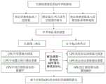
图1是本发明方法的流程示意图;Fig. 1 is a schematic flow diagram of the method of the present invention;
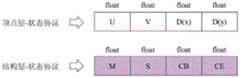
图2是状态协议的基本结构;Figure 2 is the basic structure of the state protocol;
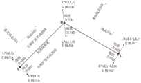
图3是U值、V值和D值的说明,以及基于状态协议的矢量线要素三角化方法说明;FIG3 is an illustration of U value, V value and D value, and an illustration of a method for triangulating vector line features based on a state protocol;
图4是线要素起点处、终点处的膨胀方法说明;Figure 4 is an illustration of the expansion method at the starting point and the end point of the line element;
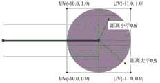
图5是以终点处为例说明在GPU如何进行圆形箭头的腐蚀方法说明;FIG5 is a diagram showing how to perform the corrosion of a circular arrow on a GPU, taking the end point as an example;
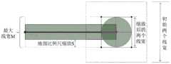
图6是M值和S值的说明,以及地图缩放后线宽处理的方法说明,其中深色填充部分为真实绘制的线宽,外层虚线部分为原始不处理前的绘制区域(即一开始三角化的结果);Figure 6 is an explanation of the M value and S value, as well as an explanation of the line width processing method after the map is zoomed, where the dark filled part is the actual drawn line width, and the outer dotted line part is the original drawing area before processing (i.e., the result of the initial triangulation);
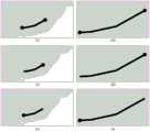
图7是利用本发明的方法绘制结果示意图,(a)为小比例尺双向圆形箭头,(b)为大比例尺双向圆形箭头端头,(c)为小比例尺终点圆形箭头,(d)为大比例尺终点圆形箭头端头,(e)为小比例尺起点圆形箭头,(f)为大比例尺起点圆形箭头端头。Figure 7 is a schematic diagram of the results drawn using the method of the present invention, (a) is a small-scale bidirectional circular arrow, (b) is the end of a large-scale bidirectional circular arrow, (c) is a small-scale end point circular arrow, (d) is the end point of a large-scale end point circular arrow, (e) is a small-scale starting point circular arrow, and (f) is the end point of a large-scale starting point circular arrow.
具体实施方式DETAILED DESCRIPTION
下面结合附图和具体实施例对本发明的技术方案做进一步说明。The technical solution of the present invention is further described below in conjunction with the accompanying drawings and specific embodiments.
图1为本发明方法的流程图。该方法包括以下步骤:首先对待绘制的矢量线要素进行初始化,指定需要在屏幕上呈现的线宽(像素单位),指定起点和终点处是否绘制圆形箭头,并确定矢量线要素的世界坐标系和屏幕坐标系之间的转换规则。接着,按照坐标转换规则将屏幕线宽转换为世界坐标系的线宽,并在世界坐标系下对矢量线要素进行三角化操作,同时在起点和终点处进行膨胀操作。然后,按照所构建的顾及线宽一致性的GPU状态协议,在CPU中获取地图缩放比例系数、初始线宽大小、起点终点圆形箭头标记等信息,并利用状态协议传递到GPU中。最终,在GPU中获取状态协议内容,在起点和终点处进行圆形箭头的腐蚀操作,实现保持线宽一致的圆形箭头绘制。FIG1 is a flow chart of the method of the present invention. The method comprises the following steps: first, the vector line element to be drawn is initialized, the line width (in pixel units) to be presented on the screen is specified, whether a circular arrow is drawn at the starting point and the end point is specified, and the conversion rule between the world coordinate system and the screen coordinate system of the vector line element is determined. Next, the screen line width is converted to the line width of the world coordinate system according to the coordinate conversion rule, and the vector line element is triangulated in the world coordinate system, and an expansion operation is performed at the starting point and the end point. Then, according to the constructed GPU state protocol that takes into account the consistency of line width, the map zoom factor, the initial line width, the circular arrow marks at the starting point and the end point, and other information are obtained in the CPU, and are passed to the GPU using the state protocol. Finally, the state protocol content is obtained in the GPU, and the circular arrow is corroded at the starting point and the end point to achieve the drawing of circular arrows with consistent line width.
在GPU绘制环境下,三角化是将矢量线要素进行线符号化绘制的关键。GPU着色器获取三角形序列,通过三角形的坐标和颜色来在屏幕上呈现待绘制对象。本质上,GPU的绘制流水线是一种无状态的过程,矢量线的线宽相关信息无法从CPU直接传递给GPU。对于带有圆形箭头的线符号而言,其需要沿着线的走向、按照确定的线宽进行绘制。基于此需求,本发明设计了一种面向带有圆形箭头的线符号保持线宽一致性绘制的状态协议。CPU中需要按照此状态协议组织信息,GPU中需要按照此状态协议解析信息。In the GPU drawing environment, triangulation is the key to drawing vector line elements in a line symbolized manner. The GPU shader obtains a triangle sequence and presents the object to be drawn on the screen through the coordinates and colors of the triangles. In essence, the GPU drawing pipeline is a stateless process, and the line width-related information of the vector line cannot be directly passed from the CPU to the GPU. For line symbols with circular arrows, they need to be drawn along the direction of the line and according to a determined line width. Based on this requirement, the present invention designs a state protocol for drawing line symbols with circular arrows while maintaining line width consistency. Information needs to be organized in the CPU according to this state protocol, and information needs to be parsed in the GPU according to this state protocol.
状态协议包含两个层面,一个是顶点层的U值,V值和D值,另一个是结构层的M值、S值、CB值和CE值,如图2所示;U值、V值、D值、M值、S值、CB值和CE值的内涵和计算方法在后续几个段落阐述。U值和V值分别是两个浮点型float数值,D值是一个二维向量,其具有X和Y方向的分量D(x)和D(y)。M值、S值、CB值和CE值是四个浮点型的数值。U-V-D三个值被组装成一个四维向量,M、S、CB、CE四个值被组装成一个四维向量。因此,面向圆形箭头的线宽一致性绘制,CPU和GPU之间的信息传递就依赖于这两个四维向量的组合。之所以将U-V-D组装成一个四维向量、将M-S-CB-CE组装成一个三维向量,是为了在CPU-GPU信息传递过程中尽可能减少信息交互的次数,批量进行传递。The state protocol contains two levels, one is the U value, V value and D value of the vertex layer, and the other is the M value, S value, CB value and CE value of the structure layer, as shown in Figure 2; the connotation and calculation method of the U value, V value, D value, M value, S value, CB value and CE value are explained in the following paragraphs. The U value and V value are two floating-point values, and the D value is a two-dimensional vector with components D(x) and D(y) in the X and Y directions. The M value, S value, CB value and CE value are four floating-point values. The three values of U-V-D are assembled into a four-dimensional vector, and the four values of M, S, CB and CE are assembled into a four-dimensional vector. Therefore, for the line width consistency drawing of the circular arrow, the information transmission between the CPU and the GPU depends on the combination of these two four-dimensional vectors. The reason why U-V-D is assembled into a four-dimensional vector and M-S-CB-CE is assembled into a three-dimensional vector is to minimize the number of information interactions during the CPU-GPU information transmission process and transmit them in batches.
对于U-V-D值而言,在图3中给出了相关的计算方法。U-V-D值是附加在每个扩展顶点上的。扩展顶点是指依据矢量线要素上的任一点,按照垂直与线走向的方向分别向两边进行扩张后得到的顶点;其中,扩张距离是线宽的一半(世界坐标系的线宽)。扩张顶点可以分为左侧点和右侧点(根据沿线走向来确定)。如图3所示,所有右侧顶点的V值都是0,所有左侧顶点的V值都是1。任一个扩张顶点的U值都是通过计算其所关联的点与起始点之间的距离得到。起始点的两个扩张顶点的U值都是0,终止点的两个扩张顶点的U值都是整个矢量线的长度除以线宽。起始点与终止点中间的任一点都是按照累积距离除以线宽得到。D值是表明扩张顶点方向的二维向量,该向量是依据扩张顶点与关联点获得。需要注意的是,D向量不能进行归一化,其向量长度就是扩张顶点与关联点之间的长度。As for the U-V-D value, the relevant calculation method is given in Figure 3. The U-V-D value is attached to each extended vertex. An extended vertex refers to a vertex obtained by expanding to both sides according to the direction perpendicular to the line direction based on any point on the vector line element; among them, the expansion distance is half of the line width (the line width of the world coordinate system). The extended vertices can be divided into left points and right points (determined according to the direction along the line). As shown in Figure 3, the V value of all right vertices is 0, and the V value of all left vertices is 1. The U value of any extended vertex is obtained by calculating the distance between the point it is associated with and the starting point. The U values of the two extended vertices at the starting point are both 0, and the U values of the two extended vertices at the ending point are the length of the entire vector line divided by the line width. Any point between the starting point and the ending point is obtained by dividing the cumulative distance by the line width. The D value is a two-dimensional vector indicating the direction of the extended vertex, which is obtained based on the extended vertex and the associated point. It should be noted that the D vector cannot be normalized, and its vector length is the length between the extended vertex and the associated point.
特别的,对于矢量线要素两个端点的U-V-D值而言,起点和终点处均需要进行膨胀处理,如图4所示。在图4中的左半部分,也就是起点位置处:首先逆着线走向扩张一个线宽,再垂直于线走向分别向两侧扩张一个线宽,形成相应的两个膨胀点(左侧点1和右侧点1);接着沿着线走向扩张一个线宽,再垂直于线走向分别向两侧扩张一个线宽,形成相应的另外两个膨胀点(左侧点2和右侧点2)。通过左侧点1、右侧点1、左侧点2和右侧点2这个四个点,构成了起点处的膨胀正方形。通过正方形的对角线进行划分,形成两个三角形传递到GPU中。类似的,图4中同样给出了终点出的膨胀方法,起点和终点的膨胀正方形是对称的:In particular, for the U-V-D values of the two endpoints of the vector line element, both the starting point and the end point need to be expanded, as shown in Figure 4. In the left half of Figure 4, that is, the starting point: first expand a line width against the direction of the line, and then expand a line width perpendicular to the direction of the line to both sides, forming two corresponding expansion points (
(1)起点处膨胀正方形的左侧点1和右侧点1,其U值均为-2.0;起点处膨胀正方形的左侧点2和右侧点2,其U值均为-1.0。另外,左侧点1和左侧点2的V值都为1,右侧点1和右侧点2的点V值都为0。四个点的D值都是各自与起点的连接向量。(1) The U values of the left and
(2)终点处膨胀正方形的左侧点1和右侧点1,其U值均为-11.0;终点处膨胀正方形的左侧点2和右侧点2,其U值均为-12.0。另外,左侧点1和左侧点2的V值都为1,右侧点1和右侧点2的点V值都为0。四个点的D值都是各自与起点的连接向量。(2) The U values of the left and
通过GPU状态协议中的U-V-D值能够判断出起点和终点的位置。既不是起点也不是终点的U值大于等于0;起点的U值小于等-1.0并且大于等于-2.0;终点的U值小于等于-10.0并且大于等于-11.0。The U-V-D value in the GPU status protocol can be used to determine the position of the start and end points. The U value of a point that is neither the start nor the end point is greater than or equal to 0; the U value of the start point is less than or equal to -1.0 and greater than or equal to -2.0; the U value of the end point is less than or equal to -10.0 and greater than or equal to -11.0.
在能够判断何处是起点、何处是终点的基础上,图5给出了基于GPU状态协议的终点处圆形箭头腐蚀方法。首先将膨胀正方形的四个点U值统一加上10.0,从而形成一个0.0到-1.0的区间。再将U值和V值组成一个点坐标(U,V),该点与(-0.5,0.5)之间的距离可以通过(-U+0.5)*(-U+0.5)+(V-0.5)*(V-0.5)来获得平方距离值。将该平方距离值与0.25(即0.5的平方值)进行比较,大于0.25的就需要进行腐蚀。由此,需要腐蚀的区域就是图5中深色圆形以外的区域。Based on the ability to determine where the starting point and the end point are, Figure 5 shows a circular arrow erosion method at the end point based on the GPU state protocol. First, add 10.0 to the U values of the four points of the expanded square to form an interval from 0.0 to -1.0. Then, the U value and the V value form a point coordinate (U, V). The distance between this point and (-0.5, 0.5) can be obtained by (-U+0.5)*(-U+0.5)+(V-0.5)*(V-0.5) to obtain the square distance value. Compare the square distance value with 0.25 (that is, the square value of 0.5). If it is greater than 0.25, it needs to be eroded. Therefore, the area that needs to be eroded is the area outside the dark circle in Figure 5.
图5中给出了终点处的工艺,在起点的工艺与之类似,不同之处在于U值需要统一加上1.0,从而也形成一个0.0到-1.0的区间。FIG5 shows the process at the end point. The process at the starting point is similar, except that the U value needs to be uniformly added with 1.0, thus forming a range of 0.0 to -1.0.
对于M-S-CB-CE值而言,M值是在初始地图比例尺下显示的最大线宽的值,S值是相对于初始地图比例尺的缩放系数,CB值和CE值是指起点和终点是否绘制圆形箭头。如果CB值小于0则在起点处不绘制圆形箭头,如果CB值大于等于0则在起点处绘制圆形箭头。同样的,如果CE值小于0则在终点处不绘制圆形箭头,如果CE值大于等于0则在终点处绘制圆形箭头。For the M-S-CB-CE value, the M value is the maximum line width displayed at the initial map scale, the S value is the scaling factor relative to the initial map scale, and the CB value and CE value refer to whether circular arrows are drawn at the start and end points. If the CB value is less than 0, no circular arrow is drawn at the start point, and if the CB value is greater than or equal to 0, a circular arrow is drawn at the start point. Similarly, if the CE value is less than 0, no circular arrow is drawn at the end point, and if the CE value is greater than or equal to 0, a circular arrow is drawn at the end point.
如图6所示,在GPU中解析状态协议里面的M-S-CB-CE值,利用以下公式重新计算任一扩张顶点的坐标:X=D(x)*M*(1.0-S)/2.0,Y=D(y)*M*(1.0-S)/2.0。D(x)和D(y)分别表示顶点方向向量的X分量和Y分量。在GPU中结合D值、M值和S值,动态计算每个点真正需要绘制的位置。在图6中外部虚线部分为初始比例尺下需要绘制的区域,中间深色填充部分为缩放比例尺之后需要绘制的区域。可以看出初始区域大,大比例尺区域小;因为在大比例尺下,矢量线要素的扩张顶点直接转换为屏幕坐标后会比初始比例尺大,所以通过D向量和M-S值来控制扩张顶点向内收缩,从而达到一致线宽的绘制效果。As shown in Figure 6, the M-S-CB-CE value in the state protocol is parsed in the GPU, and the coordinates of any expanded vertex are recalculated using the following formula: X = D(x)*M*(1.0-S)/2.0, Y = D(y)*M*(1.0-S)/2.0. D(x) and D(y) represent the X component and Y component of the vertex direction vector, respectively. In the GPU, the D value, M value, and S value are combined to dynamically calculate the position where each point actually needs to be drawn. In Figure 6, the outer dotted line part is the area that needs to be drawn at the initial scale, and the dark filled part in the middle is the area that needs to be drawn after the scale is scaled. It can be seen that the initial area is large and the large scale area is small; because at a large scale, the expanded vertex of the vector line element will be larger than the initial scale after being directly converted to screen coordinates, so the D vector and M-S value are used to control the expansion vertex to shrink inward, so as to achieve a drawing effect with consistent line width.
在图7中给出了两个不同地图比例尺,不同圆形箭头的绘制效果:(a)为小比例尺双向圆形箭头,(b)为大比例尺双向圆形箭头端头,(c)为小比例尺终点圆形箭头,(d)为大比例尺终点圆形箭头端头,(e)为小比例尺起点圆形箭头,(f)为大比例尺起点圆形箭头端头。其中,图(a)、(c)、(e)都是小比例尺绘制,图(b)、(d)、(f)都是大比例尺绘制。图(a)、(b)是双向圆形箭头的绘制效果,图(c)、(d)是终点圆形箭头的绘制效果,图(e)、(f)是起点圆形箭头绘制效果。通过交叉对比可以看出小比例尺和大比例尺的绘制效果在线宽方面是一致的。Figure 7 shows the drawing effects of different circular arrows at two different map scales: (a) is a small-scale bidirectional circular arrow, (b) is the end of a large-scale bidirectional circular arrow, (c) is a small-scale endpoint circular arrow, (d) is a large-scale endpoint circular arrow end, (e) is a small-scale starting point circular arrow, and (f) is a large-scale starting point circular arrow end. Among them, Figures (a), (c), and (e) are all drawn at a small scale, and Figures (b), (d), and (f) are all drawn at a large scale. Figures (a) and (b) are the drawing effects of bidirectional circular arrows, Figures (c) and (d) are the drawing effects of endpoint circular arrows, and Figures (e) and (f) are the drawing effects of starting point circular arrows. Through cross-comparison, it can be seen that the drawing effects of small and large scales are consistent in terms of line width.
实施例:Example:
相比于传统计算机可视化领域中的线绘制,地图绘制中的圆形箭头符号需要考虑地图比例尺的变化。GPU绘制环境下,仅通过三角形集合的坐标和颜色来控制绘制流程,无法满足保持线宽一致性的需求。所以本发明设计了一种GPU状态协议,通过此协议将线宽相关的信息打包传递给GPU,在GPU中能够有序解析这些信息;同时在起点和终点处定制了独特的膨胀和腐蚀方式,从而达到顾及线宽一致性的矢量地图线符号圆形箭头绘制。Compared with line drawing in the field of traditional computer visualization, circular arrow symbols in map drawing need to consider changes in map scale. In the GPU drawing environment, the drawing process is controlled only by the coordinates and colors of the triangle set, which cannot meet the requirement of maintaining line width consistency. Therefore, the present invention designs a GPU state protocol, through which line width-related information is packaged and passed to the GPU, and the GPU can parse this information in an orderly manner; at the same time, unique expansion and erosion methods are customized at the starting point and the end point, so as to achieve vector map line symbol circular arrow drawing that takes into account line width consistency.
以下是利用OpenGL Shader给出了本发明的实施例:The following is an embodiment of the present invention using OpenGL Shader:
(1)GPU状态协议结构(1) GPU State Protocol Structure


(2)CPU状态协议结构(2)CPU status protocol structure

Claims (4)
Translated fromChinesePriority Applications (1)
| Application Number | Priority Date | Filing Date | Title |
|---|---|---|---|
| CN201911363753.8ACN111145296B (en) | 2019-12-26 | 2019-12-26 | A method of drawing vector map line symbol circular arrows considering the consistency of line width |
Applications Claiming Priority (1)
| Application Number | Priority Date | Filing Date | Title |
|---|---|---|---|
| CN201911363753.8ACN111145296B (en) | 2019-12-26 | 2019-12-26 | A method of drawing vector map line symbol circular arrows considering the consistency of line width |
Publications (2)
| Publication Number | Publication Date |
|---|---|
| CN111145296A CN111145296A (en) | 2020-05-12 |
| CN111145296Btrue CN111145296B (en) | 2023-05-09 |
Family
ID=70520323
Family Applications (1)
| Application Number | Title | Priority Date | Filing Date |
|---|---|---|---|
| CN201911363753.8AActiveCN111145296B (en) | 2019-12-26 | 2019-12-26 | A method of drawing vector map line symbol circular arrows considering the consistency of line width |
Country Status (1)
| Country | Link |
|---|---|
| CN (1) | CN111145296B (en) |
Families Citing this family (1)
| Publication number | Priority date | Publication date | Assignee | Title |
|---|---|---|---|---|
| CN112562036B (en)* | 2020-12-10 | 2023-04-07 | 卡斯柯信号(成都)有限公司 | Method for drawing configuration system turnout icon by linear polygon |
Family Cites Families (5)
| Publication number | Priority date | Publication date | Assignee | Title |
|---|---|---|---|---|
| CN101159065A (en)* | 2007-11-08 | 2008-04-09 | 武汉大学 | Computer Automatic Drawing Method of Complicated Map Symbols |
| CN105701759B (en)* | 2016-01-11 | 2018-08-10 | 南京师范大学 | Map vector line feature turning reasonability method for drafting based on GPU |
| CN105513110A (en)* | 2016-01-11 | 2016-04-20 | 南京师范大学 | GPU-based method for drawing linetype map symbol with gradually-varied width |
| CN105719230A (en)* | 2016-01-11 | 2016-06-29 | 南京师范大学 | GPU-based color gradual change linear map symbol drafting method |
| CN109685901B (en)* | 2018-12-10 | 2022-07-22 | 西北工业大学 | Dynamic arrow plotting method in military standard mark plotting |
- 2019
- 2019-12-26CNCN201911363753.8Apatent/CN111145296B/enactiveActive
Also Published As
| Publication number | Publication date |
|---|---|
| CN111145296A (en) | 2020-05-12 |
Similar Documents
| Publication | Publication Date | Title |
|---|---|---|
| US8416244B2 (en) | Rendering a text image following a line | |
| US9495767B2 (en) | Indexed uniform styles for stroke rendering | |
| CN105513110A (en) | GPU-based method for drawing linetype map symbol with gradually-varied width | |
| JP6863693B2 (en) | Graphics processing system and method | |
| CN101751682B (en) | Preparation method of universal map | |
| CN112233215A (en) | Contour rendering method, apparatus, device and storage medium | |
| CN109544658B (en) | Map rendering method and device, storage medium and electronic device | |
| KR20140073480A (en) | Rendering a text image following a line | |
| WO2013048843A1 (en) | Label positioning technique to reduce crawling during zoom activities | |
| CN103606184A (en) | Device based on two-dimensional and three-dimensional integrated vector render engine | |
| CN111145299B (en) | Vector map solid line symbol corner drawing method considering line width consistency | |
| CN111145296B (en) | A method of drawing vector map line symbol circular arrows considering the consistency of line width | |
| CN111127297B (en) | Vector map solid line symbol drawing method considering line width consistency | |
| CN111145303B (en) | A method of drawing vector map line symbols with pointed arrows in consideration of line width consistency | |
| CN111145302B (en) | Vector map square dotted line symbol drawing method considering line width consistency | |
| CN111028353B (en) | Vector map line symbol dovetail arrow drawing method considering line width consistency | |
| CN111028352B (en) | Drawing method of vector map line symbol open pointed arrow taking into account line width consistency | |
| CN111431953B (en) | Data processing method, terminal, server and storage medium | |
| CN111145298B (en) | A method for drawing fence dotted line symbols on vector maps considering line width consistency | |
| CN111145297B (en) | Drawing Method of Vector Map Line Symbol Diamond Arrow Considering Line Width Consistency | |
| CN111145295B (en) | Vector map line symbol half-dovetail arrow drawing method considering line width consistency | |
| CN111028351B (en) | Vector map line symbol half-sharp angle arrow drawing method considering line width consistency | |
| CN111145301B (en) | A method for drawing the end of solid-line symbols on vector maps considering the consistency of line width | |
| CN111080744B (en) | Vector map line symbol half-open pointed arrow drawing method considering line width consistency | |
| CN111127589B (en) | A method for drawing circular dotted line symbols on vector maps taking into account the consistency of line width |
Legal Events
| Date | Code | Title | Description |
|---|---|---|---|
| PB01 | Publication | ||
| PB01 | Publication | ||
| SE01 | Entry into force of request for substantive examination | ||
| SE01 | Entry into force of request for substantive examination | ||
| GR01 | Patent grant | ||
| GR01 | Patent grant |