CN111113478B - Rotary joint of a reconfigurable mechanism - Google Patents
Rotary joint of a reconfigurable mechanismDownload PDFInfo
- Publication number
- CN111113478B CN111113478BCN202010030149.XACN202010030149ACN111113478BCN 111113478 BCN111113478 BCN 111113478BCN 202010030149 ACN202010030149 ACN 202010030149ACN 111113478 BCN111113478 BCN 111113478B
- Authority
- CN
- China
- Prior art keywords
- gear
- sliding block
- output
- lead screw
- switching device
- Prior art date
- Legal status (The legal status is an assumption and is not a legal conclusion. Google has not performed a legal analysis and makes no representation as to the accuracy of the status listed.)
- Active
Links
- 230000007246mechanismEffects0.000titleclaimsabstractdescription30
- 230000005540biological transmissionEffects0.000claimsdescription28
- 230000033001locomotionEffects0.000claimsdescription13
- 230000001360synchronised effectEffects0.000claimsdescription2
- 238000000034methodMethods0.000abstractdescription9
- 238000010168coupling processMethods0.000abstractdescription7
- 230000008878couplingEffects0.000abstractdescription6
- 238000005859coupling reactionMethods0.000abstractdescription6
- 230000009286beneficial effectEffects0.000abstractdescription2
- 238000010586diagramMethods0.000description8
- 230000008859changeEffects0.000description4
- 230000008569processEffects0.000description4
- 238000005516engineering processMethods0.000description2
- 238000009434installationMethods0.000description2
- 238000004519manufacturing processMethods0.000description2
- 238000004891communicationMethods0.000description1
- 230000007547defectEffects0.000description1
- 238000013461designMethods0.000description1
- 238000010297mechanical methods and processMethods0.000description1
- 238000012986modificationMethods0.000description1
- 230000004048modificationEffects0.000description1
- 238000011160researchMethods0.000description1
Images


Classifications
- B—PERFORMING OPERATIONS; TRANSPORTING
- B25—HAND TOOLS; PORTABLE POWER-DRIVEN TOOLS; MANIPULATORS
- B25J—MANIPULATORS; CHAMBERS PROVIDED WITH MANIPULATION DEVICES
- B25J17/00—Joints
- B—PERFORMING OPERATIONS; TRANSPORTING
- B25—HAND TOOLS; PORTABLE POWER-DRIVEN TOOLS; MANIPULATORS
- B25J—MANIPULATORS; CHAMBERS PROVIDED WITH MANIPULATION DEVICES
- B25J9/00—Programme-controlled manipulators
- B25J9/08—Programme-controlled manipulators characterised by modular constructions
- B—PERFORMING OPERATIONS; TRANSPORTING
- B25—HAND TOOLS; PORTABLE POWER-DRIVEN TOOLS; MANIPULATORS
- B25J—MANIPULATORS; CHAMBERS PROVIDED WITH MANIPULATION DEVICES
- B25J9/00—Programme-controlled manipulators
- B25J9/10—Programme-controlled manipulators characterised by positioning means for manipulator elements
- B25J9/102—Gears specially adapted therefor, e.g. reduction gears
Landscapes
- Engineering & Computer Science (AREA)
- Robotics (AREA)
- Mechanical Engineering (AREA)
- Transmission Devices (AREA)
Abstract
Description
Translated fromChinese技术领域:Technical field:
本发明涉及的机器人制造的技术领域。更具体地说,尤其涉及一种可重构机构的转动关节。The present invention relates to the technical field of robot manufacturing. More specifically, it particularly relates to a reconfigurable mechanism pivot joint.
背景技术:Background technique:
人类对探索工具的要求越来越高,特别对于那些高危,环境恶劣,生物不能到达的应用场景。5G通讯技术越发的提高了超远距离信息传递的低延迟率,这使得远距离操控技术变的更有价值,而在硬件方面没有能较好实现“一机多能”的高适应性载体。因此,无论是移动机器人还是操作用的机械臂,都应具有一定的适应非结构化环境的能力。Humans have increasingly higher requirements for exploration tools, especially for those application scenarios that are high-risk, harsh environments, and inaccessible to living things. 5G communication technology has increasingly improved the low-latency rate of ultra-long-distance information transmission, which makes long-distance control technology more valuable, but there is no highly adaptable carrier that can better achieve "one machine with multiple functions" in terms of hardware. Therefore, whether it is a mobile robot or a manipulator for operation, it should have a certain ability to adapt to the unstructured environment.
为应对上述现实需求,近年来,一些新概念被提出,诸如:多操作模式、多移动模式、可重构、变结构。依托上述概念的机构也相继应运而生,例如:变自由度机构、可重构机构、变拓扑机构、多操作模式机构、变胞机构以及运动分岔机构。这些机构共有的特点是:自由度可变、结构可变。当机构拓扑结构发生改变时,机构的自由度会随之改变;而自由度的改变,往往意味着驱动布置方案的改变。这时机构中的某些运动副的状态也应当随之改变。这是与性质固定的传统机构存在区别的地方。In order to meet the above-mentioned practical demands, in recent years, some new concepts have been proposed, such as: multi-operation mode, multi-movement mode, reconfigurable, and variable structure. Mechanisms based on the above concepts have also emerged one after another, such as: variable degree of freedom mechanism, reconfigurable mechanism, variable topology mechanism, multi-operation mode mechanism, metamorphic mechanism and kinematic bifurcation mechanism. The common features of these mechanisms are: variable degrees of freedom and variable structure. When the mechanism topology changes, the degree of freedom of the mechanism will change accordingly; and the change of the degree of freedom often means the change of the driving arrangement. At this time, the state of some kinematic pairs in the mechanism should also change accordingly. This is where there is a difference from traditional institutions of a fixed nature.
转动副是存在于机构中较多的一种连接方式,而转动副一般存在主动和被动两种状态。一方面,以往机构由于缺乏上述需求,转动副做驱动时常常与驱动电机直接固连在一起,与被动状态的纯转动副不是同时存在的;另一方面,到目前为止,上述的可重构机构虽然提出但实际应用还非常稀少。然而,上述问题是在不远的将来,可重构机构应用和实际制作中,终将面对的一个问题。The rotating pair is a connection method that exists in many mechanisms, and the rotating pair generally exists in two states: active and passive. On the one hand, due to the lack of the above-mentioned requirements in the previous mechanism, the rotating pair is often directly connected to the driving motor when it is driven, and does not exist at the same time as the pure rotating pair in the passive state; on the other hand, so far, the above-mentioned reconfigurable Although institutions are proposed, practical application is still very rare. However, the above problem is a problem that will eventually be faced in the application and actual production of reconfigurable mechanisms in the near future.
中国专利文献(201910271321.8)公开了一种基于运动分岔机构的多模式混联机械臂,这是一种具有两种操作模式的混联机械臂,两种操作模式需要两种不同的驱动方案,本发明可为此提供解决方案。Chinese patent document (201910271321.8) discloses a multi-mode hybrid manipulator based on a kinematic bifurcation mechanism, which is a hybrid manipulator with two operation modes, which require two different drive schemes, The present invention can provide a solution for this.
综上,开发出一种可实现主动/被动切换的转动副是十分必要且有实际应用价值的。In conclusion, it is very necessary and practical to develop a rotating pair that can realize active/passive switching.
发明内容:Invention content:
本发明的目的就是为了克服上述现有技术存在的缺陷而提供一种应用于可重构机构并可实现主、被动切换的转动关节。The purpose of the present invention is to provide a rotary joint which is applied to a reconfigurable mechanism and can realize active and passive switching in order to overcome the above-mentioned defects of the prior art.
这是一个目前涉及相对较为稀少的领域,该转动关节可实现主动、被动两种状态,具有方便,其工作原理简单,可提高结构利用率的特点,用于实现可重构机构的模式切换,并保证各模式的正常运行。This is a relatively sparse field at present. The rotary joint can realize active and passive states. It is convenient, its working principle is simple, and it can improve the utilization rate of the structure. It is used to realize the mode switching of the reconfigurable mechanism. And ensure the normal operation of each mode.
本发明的上述技术问题主要是通过下述技术方案得以解决的:一种可重构机构的转动关节,包括电器模块和机械模块;其中,机械模块包括:切换装置、齿轮组件、舵机和输出杆;通过切换装置使齿轮组件分离或耦合舵机,舵机的输出端可驱动输出杆。The above-mentioned technical problems of the present invention are mainly solved by the following technical solutions: a rotating joint of a reconfigurable mechanism, including an electrical module and a mechanical module; wherein, the mechanical module includes: a switching device, a gear assembly, a steering gear and an output rod; the gear assembly is separated or coupled with the steering gear through the switching device, and the output end of the steering gear can drive the output rod.
在一个实施例中,切换装置包括第一驱动元件、丝杠、滑块组件和连接杆;其中,第一驱动元件的输出端连接竖直方向的丝杠,滑块组件连接于丝杠顶部,在滑块组件的一侧安装水平方向的连接杆。In one embodiment, the switching device includes a first driving element, a lead screw, a slider assembly and a connecting rod; wherein, the output end of the first driving element is connected to the vertical lead screw, and the slider assembly is connected to the top of the lead screw, Install a horizontal connecting rod on one side of the slider assembly.
在一个实施例中,齿轮组件包括第一齿轮和第二齿轮;第一齿轮连接在所述连接杆远离所述滑动组件的一端,第二齿轮设在第一齿轮的上方并与所述输出杆连接,在所述第一驱动元件的驱动下,所述丝杠向上转动,驱动所述滑块组件和所述连接杆向上移动,带动第一齿轮和第二齿轮啮合。In one embodiment, the gear assembly includes a first gear and a second gear; the first gear is connected to the end of the connecting rod away from the sliding assembly, and the second gear is arranged above the first gear and is connected with the output rod Connected, under the driving of the first driving element, the lead screw rotates upward, drives the slider assembly and the connecting rod to move upward, and drives the first gear and the second gear to mesh.
在一个实施例中,所述第一齿轮和所述第二齿轮啮合后,所述切换装置停止运转,所述舵机的输出端驱动所述第一齿轮,经过所述第二齿轮的动力传递后,由所述输出杆转动输出。In one embodiment, after the first gear and the second gear are engaged, the switching device stops running, the output end of the steering gear drives the first gear, and the power is transmitted through the second gear After that, the output rod is rotated and output.
在一个实施例中,所述滑块组件包括第一滑块和第二滑块,第二滑块设在第一滑块的一侧,在第一滑块的顶部设有阶梯状通孔,螺母通过阶梯状通孔后连接于所述丝杠顶部,在第一滑块和第二滑块的侧部各设有两个等距离的孔,所述连接杆的一端进入等距离的孔中并从第二滑块的一侧延伸出来。In one embodiment, the sliding block assembly includes a first sliding block and a second sliding block, the second sliding block is provided on one side of the first sliding block, and a stepped through hole is provided on the top of the first sliding block, The nut is connected to the top of the lead screw after passing through the stepped through hole. Two equidistant holes are provided on the sides of the first slider and the second slider, and one end of the connecting rod enters the equidistant holes. and extend from one side of the second slider.
在一个实施例中,还包括固定所述切换装置的支架部件,支架部件包括一个L型支架,在L型支架底部设有支座,在L型支架顶部设有安装所述第一滑块的连接块,在连接块上设有连接所述第一滑块的连接孔,所述第一驱动元件设在支座开设的空腔内,第一驱动元件的顶部为输出端并与所述丝杠连接。In one embodiment, it also includes a bracket part for fixing the switching device, the bracket part includes an L-shaped bracket, a support is provided at the bottom of the L-shaped bracket, and a top of the L-shaped bracket is provided with a bracket for installing the first slider. The connecting block is provided with a connecting hole for connecting the first slider, the first driving element is arranged in the cavity opened by the support, and the top of the first driving element is the output end and is connected with the wire bar connection.
在一个实施例中,所述切换装置及与其匹配的所述支架部件为两套,分别设在所述舵机的两侧。In one embodiment, there are two sets of the switching device and the bracket parts matched therewith, which are respectively arranged on both sides of the steering gear.
在一个实施例中,所述转动关节还包括上面板和下面板,且分别设在所述舵机的上方和下方,上、下面板之间通过螺栓件连接,在所述切换装置的一侧安装所述电器模块,所述电器模块安装在上、下面板之间,包括控制板、控制板电源和丝杠驱动电源。In one embodiment, the rotating joint further includes an upper panel and a lower panel, which are respectively arranged above and below the steering gear. The upper and lower panels are connected by bolts, and are located on one side of the switching device. The electrical module is installed, the electrical module is installed between the upper and lower panels, and includes a control board, a control board power supply and a lead screw drive power supply.
在一个实施例中,还包括舵盘,所述输出杆的一端通过螺栓件与舵盘固定连接,所述输出杆的另一端与所述下面板活动连接;所述舵机的输出端通过第一传动轴与所述第一齿轮连接,所述第二齿轮通过第二传动轴与所述舵盘连接。In one embodiment, it also includes a steering wheel, one end of the output rod is fixedly connected to the steering wheel through a bolt member, and the other end of the output rod is movably connected to the lower panel; the output end of the steering gear passes through the first A transmission shaft is connected with the first gear, and the second gear is connected with the steering wheel through the second transmission shaft.
在一个实施例中,:所述控制器发出使丝杠转动的信号,所述丝杠的旋转转化为螺母的上下移动,进而带动所述滑块组件上下移动,所述滑块组件通过所述连接杆将移动传递给所述第一齿轮上移,所述第一齿轮与所述第二齿轮逐渐接触,所述第二齿轮将自由调整,逐渐实现所述第一、第二齿轮的耦合,此时所述控制板的输出信号控制所述丝杠停止转动,使所述第一、第二齿轮处于抱死状态;通过所述舵机的驱动输出,并通过所述第一传动轴、所述第一、第二齿轮和所述舵盘的传动同步,使力矩输出,转动关节由被动转动副切换为主动转动副。In one embodiment, the controller sends a signal to rotate the lead screw, and the rotation of the lead screw is converted into the up and down movement of the nut, thereby driving the slider assembly to move up and down, and the slider assembly passes the The connecting rod transmits the movement to the first gear to move up, the first gear and the second gear are gradually contacted, the second gear will be adjusted freely, and the coupling of the first and second gears is gradually realized. At this time, the output signal of the control board controls the lead screw to stop rotating, so that the first and second gears are in a locked state; through the driving output of the steering gear, and through the first transmission shaft, the The transmission of the first and second gears and the steering wheel is synchronized, so that the torque is output, and the rotating joint is switched from a passive rotating pair to an active rotating pair.
本发明的主要有益效果是:本发明的转动关节兼具了转动副主动及被动两种状态,可实现主动、被动的切换。通过控制丝杆的旋转,实现两耦合齿轮的离合,具有工作原理简单高效、结构紧凑、控制容易等优点。应用于实现可重构机构的模式切换,并保证各模式下机构均能正常运行。The main beneficial effects of the present invention are as follows: the rotating joint of the present invention has both active and passive states of the rotating pair, and can realize active and passive switching. By controlling the rotation of the screw rod, the clutch of the two coupling gears is realized, which has the advantages of simple and efficient working principle, compact structure, and easy control. It is applied to realize the mode switching of the reconfigurable mechanism and ensure the normal operation of the mechanism in each mode.
附图说明:Description of drawings:
本发明上述的以及其他的特征、性质和优势将通过下面结合附图和实施例的描述而变的更加明显,在附图中相同的附图标记始终表示相同的特征,其中:The above and other features, properties and advantages of the present invention will become more apparent from the following description taken in conjunction with the accompanying drawings and embodiments, in which like reference numerals refer to like features throughout, wherein:
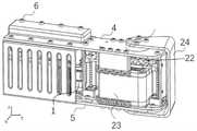
图1是本发明一实施例中,一种可重构机构的转动关节的整体结构示意图;1 is a schematic diagram of the overall structure of a rotating joint of a reconfigurable mechanism according to an embodiment of the present invention;
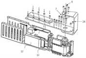
图2是本发明一实施例中,一种可重构机构的转动关节的整体结构的爆炸图;2 is an exploded view of the overall structure of a rotating joint of a reconfigurable mechanism according to an embodiment of the present invention;
图3是本发明一实施例中,舵机传动轴线方向相关部件的连接方式爆炸示意图.;3 is an exploded schematic diagram of the connection mode of the relevant components in the direction of the steering gear transmission axis in an embodiment of the present invention;
图4是本发明一实施例中,切换装置的结构安装示意图;4 is a schematic diagram of the structure and installation of the switching device according to an embodiment of the present invention;
图5是本发明一实施例中,丝杠与支架的安装示意图;5 is a schematic diagram of the installation of the lead screw and the bracket in an embodiment of the present invention;
图6是本发明一实施例中,舵机的输出端与第一齿轮的连接示意图;6 is a schematic diagram of the connection between the output end of the steering gear and the first gear in an embodiment of the present invention;
图7是本发明一实施例中,第二齿轮与舵盘的连接示意图;FIG. 7 is a schematic diagram of the connection between the second gear and the steering wheel in an embodiment of the present invention;
图8是本发明一实施例中,舵机与输出杆的连接方式示意图;8 is a schematic diagram of the connection between the steering gear and the output rod in an embodiment of the present invention;
图9是本发明一实施例中,第一齿轮和第二齿轮离合过程的工作原理示意图。FIG. 9 is a schematic diagram of the working principle of the clutching process of the first gear and the second gear in an embodiment of the present invention.
具体实施方式:Detailed ways:
下面结合附图对本发明的优选实施例进行详细阐述,以使本发明的优点和特征能更易于被本领域技术人员理解,从而对本发明的保护范围做出更为清楚明确的界定。The preferred embodiments of the present invention will be described in detail below with reference to the accompanying drawings, so that the advantages and features of the present invention can be more easily understood by those skilled in the art, and the protection scope of the present invention can be more clearly defined.
参考图1并结合图2-图9,在图1的实施例中,一种可重构机构的转动关节包括电器模块1和机械模块;其中机械模块包括:切换装置21、齿轮组件22、舵机23和输出杆24;通过切换装置21使齿轮组件22分离或耦合舵机23,舵机23的输出端可驱动输出杆24。Referring to FIG. 1 and in conjunction with FIGS. 2 to 9 , in the embodiment of FIG. 1 , a rotary joint of a reconfigurable mechanism includes an
参考图4,作为一个优选实施例,切换装置21包括第一驱动元件211、丝杠212、滑块组件213和连接杆214;其中,第一驱动元件211的输出端连接竖直方向的丝杠212,滑块组件213连接在丝杠212顶部,在滑块组件的一侧安装水平方向的连接杆214。4, as a preferred embodiment, the
参考图3,作为一个优选实施例,齿轮组件22包括第一齿轮221和第二齿轮222;第一齿轮221连接在连接杆214远离滑动组件213的一端,第二齿轮222设在第一齿轮221的上方并与输出杆24连接,在第一驱动元件211的驱动下,丝杠212向上转动,驱动滑块组件213和连接杆214向上移动,带动第一齿轮221和第二齿轮222啮合。Referring to FIG. 3 , as a preferred embodiment, the
进一步地,第一齿轮221和第二齿轮222啮合后,切换装置21停止运转,舵机23的输出端驱动第一齿轮221,经过第二齿轮222的动力传递后,由输出杆24转动输出。Further, after the
参考图4,作为一个优选实施例,滑块组件213包括第一滑块215和第二滑块216,第二滑块216设在第一滑块215的一侧,在第一滑块216的顶部设有阶梯状通孔217,螺母218通过阶梯状通孔217后连接于丝杠212的顶部,在第一滑块215和第二滑块216的侧部各设有两个等距离的孔219,所述连接杆214的一端进入等距离的孔219中并从第二滑块216的一侧延伸出来。Referring to FIG. 4 , as a preferred embodiment, the
继续参考图4,作为一个优选实施项,还包括固定切换装置的支架部件3,支架部件3包括一个L型支架31,在L型支架底部设有支座32,在L型支架顶部设有安装第一滑块的连接块33,在连接块33上设有连接第一滑块的连接孔34,第一驱动元件211设在支座开设的空腔35内,第一驱动元件211的顶部为输出端并与丝杠212连接。Continuing to refer to FIG. 4 , as a preferred embodiment, it also includes a
进一步地,切换装置21及与其匹配的支架部件3为两套,分别设在所述舵机23的两侧。Further, there are two sets of the
继续参考图1,作为一个优选实施项,转动关节还包括上面板4和下面板5,且分别设在舵机23的上方和下方,上、下面板之间通过螺栓件6连接,在切换装置21的一侧安装电器模块1,电器模块1安装在上、下面板之间,包括控制板11、控制板电源12和丝杠驱动电源(图中未标注)。Continuing to refer to FIG. 1 , as a preferred implementation item, the rotary joint also includes an upper panel 4 and a
进一步地,还包括舵盘7,输出杆24的一端通过螺栓件6与舵盘7固定连接,输出杆24的另一端与下面板5活动连接;舵机23的输出端通过第一传动轴8与第一齿轮221连接,第二齿轮222通过第二传动轴9与舵盘7连接。Further, it also includes a
进一步地,控制器发出使丝杠转动的信号,丝杠212的旋转转化为螺母218的上下移动,进而带动滑块组件213上下移动,滑块组件212通过连接杆214将移动传递给第一齿轮221上移,第一齿轮221与第二齿轮222开始逐渐接触,第二齿轮222将自由调整,逐渐实现第一齿轮221、第二齿轮222的耦合,此时控制板的输出信号控制丝杠212停止转动,使第一齿轮221、第二齿轮222处于抱死状态;通过舵机23的驱动输出,并通过第一传动轴、第一、第二齿轮和舵盘的传动同步,使力矩输出,转动关节由被动转动副切换为主动转动副。Further, the controller sends a signal to rotate the lead screw, and the rotation of the
继续参考图1,可以理解的是,上面板4和下面板5起到支撑和承载作用,上面板4与下面板5之间可以通过螺栓6实现固连。Continuing to refer to FIG. 1 , it can be understood that the upper panel 4 and the
继续参考图8,可以理解的是,输出杆的一端可以通过螺栓件78与舵盘7实现固连,而另一端也可以通过螺栓78与紧固螺母77和垫片76之间实现活动连接。Continuing to refer to FIG. 8 , it can be understood that one end of the output rod can be fixedly connected to the
同样可以理解的是,机械模块可用于实现舵机的力矩输出的通断,具体是通过控制一对耦合齿轮(即第一齿轮和第二齿轮)的离合来实现的。It can also be understood that the mechanical module can be used to realize the on-off of the torque output of the steering gear, which is specifically realized by controlling the clutch of a pair of coupled gears (ie, the first gear and the second gear).
继续参考图6,可以理解的是,靠近舵机一侧的第一齿轮221可以通过第一传动轴232与舵机23之间实现固连,第一传动轴232的特征在于其上开有键槽,一端有螺纹,与舵机的输出轴之间可以实现螺栓连接。舵机的输出轴231、第一传动轴232及第一齿轮221的轴线重合;第一齿轮221及第一传动轴232通过键233实现圆周方向的定位和实现传动。Continuing to refer to FIG. 6 , it can be understood that the
继续参考图7,可以理解的是,第二齿轮的相关连接具体为,第二齿轮222、第二传动轴9及舵盘7之间的轴线共线,上述三者的特征在于,其上均开有键槽91,并通过键槽91实现传动;第二齿轮222及第二传动轴9上均开有圆形通孔92,并通过圆柱销93与第二传动轴9之间实现固连;第二传动轴9的一端有键94,第二传动轴可以放置于轴承95上,并通过键94将力矩传给舵盘7。Continuing to refer to FIG. 7 , it can be understood that the relevant connection of the second gear is that the axes between the
第一齿轮221、第二齿轮222之间的离合可以通过第一齿轮221沿z方向的上下移动实现的,而第一齿轮221的移动是通过一组丝杠212来实现的。The clutch between the
继续参考图5,丝杠212通过两个螺栓件6与支架部件3实现固连,支架部件3通过上下面的螺栓件固定于上、下面板上。Continuing to refer to FIG. 5 , the
继续参考图4,丝杠212上可以有螺母218,螺母218与滑块组件213通过转动副连接,第一滑块215及第二滑块216之间开有等距共轴的两个通孔219,两根连接杆214可以穿过通孔219。第二滑块216与第一齿轮221之间可以通过轴承实现连接。工作时,第二滑块216搭载着第一齿轮221,不限制第一齿轮221的旋转运动,并实现第一齿轮221在一定行程内的上下移动。Continuing to refer to FIG. 4 , the
本发明的工作原理如下:The working principle of the present invention is as follows:
继续参考图9,从左至右为关节从被动状态切换至主动状态的耦合过程,实现此过程的具体方式如下,Continuing to refer to Figure 9, from left to right is the coupling process of the joint switching from the passive state to the active state. The specific way to realize this process is as follows:
控制器发出使丝杠转动的信号,丝杠的旋转运动转化为螺母218的上下移动,进而带动第一滑块215移动,第一滑块215通过连接杆214将移动传递给第二滑块216,第二滑块216搭载第一齿轮221上移,由于第一齿轮221可以自由转动,第一齿轮221与第二齿轮222逐渐接触,第一齿轮221将自由调整,逐渐实现两个齿轮的耦合,此时控制板输出信号控制丝杠212停止转动,使两齿轮处于抱死状态。之后舵机的输出轴231、第一传动轴232、第一齿轮221、第二齿轮222、第二传动轴9及舵盘7成为一体,力矩得以输出,关节由被动转动副切换为驱动转动副。The controller sends a signal to rotate the lead screw, and the rotational motion of the lead screw is converted into the up and down movement of the
可以理解的是,有主动状态切换至被动状态的过程则与上述过程相反。It can be understood that the process of switching from an active state to a passive state is opposite to the above process.
应当强调的是本发明所涉领域的相关研究还很稀少,本发明将为可重构机构各模式的正常运行提供普适性的应用基础。It should be emphasized that the related research in the field to which the present invention relates is still scarce, and the present invention will provide a universal application basis for the normal operation of various modes of the reconfigurable mechanism.
发明的创新点在于通过传动轴的耦合齿轮的离合实现。而实现齿轮离合的方式有多种,诸如:机械结构、磁力等。在本发明中考虑到机械方式的可靠性高,故采用了丝杠的具体方式。使用强力磁铁的吸合亦能实现齿轮的离合,与此类似的所有方式的使用以实现本发明的功能和主体设计思想的,这些等同的变形或替换均包含在本申请权利要求所限定的范围内。The innovation of the invention is realized by the clutch of the coupling gear of the transmission shaft. There are many ways to realize the gear clutch, such as: mechanical structure, magnetic force and so on. In the present invention, considering the high reliability of the mechanical method, the specific method of the screw is adopted. The clutch of the gear can also be realized by the attraction of the strong magnet, and all the similar methods are used to realize the function and main design idea of the present invention, and these equivalent deformations or replacements are included in the scope defined by the claims of the present application Inside.
上述实施例是提供给熟悉本领域内的人员来实现或使用本发明的,熟悉本领域的人员可在不脱离本发明的发明思想的情况下,对上述实施例做出种种修改或变化,因而本发明的保护范围并不被上述实施例所限,而应该是符合权利要求书提到的创新性特征的最大范围。The above-mentioned embodiments are provided for those skilled in the art to realize or use the present invention. Those skilled in the art can make various modifications or changes to the above-mentioned embodiments without departing from the inventive concept of the present invention. The protection scope of the present invention is not limited by the above-mentioned embodiments, but should be the maximum scope conforming to the innovative features mentioned in the claims.
Claims (8)
Priority Applications (1)
| Application Number | Priority Date | Filing Date | Title |
|---|---|---|---|
| CN202010030149.XACN111113478B (en) | 2020-01-13 | 2020-01-13 | Rotary joint of a reconfigurable mechanism |
Applications Claiming Priority (1)
| Application Number | Priority Date | Filing Date | Title |
|---|---|---|---|
| CN202010030149.XACN111113478B (en) | 2020-01-13 | 2020-01-13 | Rotary joint of a reconfigurable mechanism |
Publications (2)
| Publication Number | Publication Date |
|---|---|
| CN111113478A CN111113478A (en) | 2020-05-08 |
| CN111113478Btrue CN111113478B (en) | 2022-09-13 |
Family
ID=70488095
Family Applications (1)
| Application Number | Title | Priority Date | Filing Date |
|---|---|---|---|
| CN202010030149.XAActiveCN111113478B (en) | 2020-01-13 | 2020-01-13 | Rotary joint of a reconfigurable mechanism |
Country Status (1)
| Country | Link |
|---|---|
| CN (1) | CN111113478B (en) |
Families Citing this family (1)
| Publication number | Priority date | Publication date | Assignee | Title |
|---|---|---|---|---|
| CN119975739B (en)* | 2025-01-16 | 2025-09-30 | 北京科技大学 | Bionic robot fish system for realizing active and passive mode switching and control method |
Citations (9)
| Publication number | Priority date | Publication date | Assignee | Title |
|---|---|---|---|---|
| JP2006218563A (en)* | 2005-02-09 | 2006-08-24 | National Univ Corp Shizuoka Univ | Robot mechanism |
| CN101024286A (en)* | 2007-03-29 | 2007-08-29 | 廊坊智通机器人系统有限公司 | Active-passive joint-arm type measuring robot |
| CN103264389A (en)* | 2013-05-14 | 2013-08-28 | 东南大学 | Omni-directional moving unit module structure of modularized self-reconfiguration robot |
| CN203283311U (en)* | 2013-05-29 | 2013-11-13 | 华南理工大学 | Robot wheel movement module with plane movement and route movement |
| CN104723354A (en)* | 2013-12-20 | 2015-06-24 | 中国科学院沈阳自动化研究所 | Mechanical impedance parameter adjustable flexible-drive rotary joint of robot |
| CN106272350A (en)* | 2016-09-05 | 2017-01-04 | 清华大学 | A kind of RRR parallel institution driving joint variable props up chain apparatus |
| CN106926227A (en)* | 2015-12-31 | 2017-07-07 | 中国科学院沈阳自动化研究所 | A kind of open-ended modularity mechanical arm |
| CN206475959U (en)* | 2016-12-28 | 2017-09-08 | 深圳供电局有限公司 | Isomorphic modular robot crawler-type moving mechanism |
| CN110614652A (en)* | 2019-09-26 | 2019-12-27 | 今立机器人(上海)有限公司 | Single-degree-of-freedom kinematic joint of robot |
- 2020
- 2020-01-13CNCN202010030149.XApatent/CN111113478B/enactiveActive
Patent Citations (9)
| Publication number | Priority date | Publication date | Assignee | Title |
|---|---|---|---|---|
| JP2006218563A (en)* | 2005-02-09 | 2006-08-24 | National Univ Corp Shizuoka Univ | Robot mechanism |
| CN101024286A (en)* | 2007-03-29 | 2007-08-29 | 廊坊智通机器人系统有限公司 | Active-passive joint-arm type measuring robot |
| CN103264389A (en)* | 2013-05-14 | 2013-08-28 | 东南大学 | Omni-directional moving unit module structure of modularized self-reconfiguration robot |
| CN203283311U (en)* | 2013-05-29 | 2013-11-13 | 华南理工大学 | Robot wheel movement module with plane movement and route movement |
| CN104723354A (en)* | 2013-12-20 | 2015-06-24 | 中国科学院沈阳自动化研究所 | Mechanical impedance parameter adjustable flexible-drive rotary joint of robot |
| CN106926227A (en)* | 2015-12-31 | 2017-07-07 | 中国科学院沈阳自动化研究所 | A kind of open-ended modularity mechanical arm |
| CN106272350A (en)* | 2016-09-05 | 2017-01-04 | 清华大学 | A kind of RRR parallel institution driving joint variable props up chain apparatus |
| CN206475959U (en)* | 2016-12-28 | 2017-09-08 | 深圳供电局有限公司 | Isomorphic modular robot crawler-type moving mechanism |
| CN110614652A (en)* | 2019-09-26 | 2019-12-27 | 今立机器人(上海)有限公司 | Single-degree-of-freedom kinematic joint of robot |
Also Published As
| Publication number | Publication date |
|---|---|
| CN111113478A (en) | 2020-05-08 |
Similar Documents
| Publication | Publication Date | Title |
|---|---|---|
| CN101596717A (en) | Compact type intelligent switch joint | |
| CN109779437B (en) | Cabin door driving system | |
| CN111113478B (en) | Rotary joint of a reconfigurable mechanism | |
| CN219095130U (en) | Multi-degree-of-freedom desktop mechanical arm | |
| CN201456003U (en) | Compact intelligent joint | |
| CN105171723A (en) | Integrated two-degree-of-freedom manipulator and control system thereof | |
| CN110650363B (en) | Lifting and turning device for television camera | |
| CN211415236U (en) | Driving joint based on double-stator frameless torque motor and industrial robot | |
| CN110861120B (en) | Drive joint based on double-stator frameless torque motor and its application | |
| CN208179528U (en) | A kind of single driving three-freedom mechanical arm of energy conservation | |
| CN110010385B (en) | Transmission mechanism of auxiliary switch | |
| CN112621733A (en) | Four-degree-of-freedom robot | |
| CN209207509U (en) | A kind of tetra- axis robot of SCARA three or four axis deceleration mechanism and robot | |
| CN217650396U (en) | Mechanical arm and carrying equipment | |
| CN115535313B (en) | Quick change device with locking function and torque output function are in an organic whole | |
| CN109483585A (en) | A kind of adaptive strain palm mechanism | |
| CN101863031A (en) | A multi-dimensional manipulator driving device for semiconductor special equipment | |
| CN222963428U (en) | A high-precision, shock-resistant and explosion-proof electric actuator | |
| CN217507150U (en) | Auxiliary switch transmission device | |
| CN216950004U (en) | Automatic door opener of machining center | |
| CN215920522U (en) | Two-degree-of-freedom plane joint mechanical arm | |
| CN223177322U (en) | A space-saving automobile locking mechanism | |
| CN119304923B (en) | A three-degree-of-freedom robot wrist with two-way active clutch and braking functions | |
| CN221850254U (en) | A motor coordinated rotation joint module | |
| CN223044546U (en) | A mechanical arm |
Legal Events
| Date | Code | Title | Description |
|---|---|---|---|
| PB01 | Publication | ||
| PB01 | Publication | ||
| SE01 | Entry into force of request for substantive examination | ||
| SE01 | Entry into force of request for substantive examination | ||
| GR01 | Patent grant | ||
| GR01 | Patent grant | ||
| TR01 | Transfer of patent right | ||
| TR01 | Transfer of patent right | Effective date of registration:20240201 Address after:201400 floor 5, building 11, No. 6055, Jinhai highway, Fengxian District, Shanghai Patentee after:Shanghai Keyou Sai Intelligent Technology Co.,Ltd. Country or region after:China Address before:201620 No. 333, Longteng Road, Shanghai, Songjiang District Patentee before:SHANGHAI University OF ENGINEERING SCIENCE Country or region before:China |