CN111112912B - A kind of turbine shell rocker arm welding tool - Google Patents
A kind of turbine shell rocker arm welding toolDownload PDFInfo
- Publication number
- CN111112912B CN111112912BCN201911367215.6ACN201911367215ACN111112912BCN 111112912 BCN111112912 BCN 111112912BCN 201911367215 ACN201911367215 ACN 201911367215ACN 111112912 BCN111112912 BCN 111112912B
- Authority
- CN
- China
- Prior art keywords
- turbine shell
- positioning
- rocker arm
- plate
- limiting
- Prior art date
- Legal status (The legal status is an assumption and is not a legal conclusion. Google has not performed a legal analysis and makes no representation as to the accuracy of the status listed.)
- Active
Links
- 238000003466weldingMethods0.000titleclaimsabstractdescription43
- 230000007246mechanismEffects0.000claimsabstractdescription25
- 238000001514detection methodMethods0.000claimsdescription11
- 230000000903blocking effectEffects0.000claims2
- 238000011900installation processMethods0.000abstractdescription5
- 238000000034methodMethods0.000description5
- 230000008569processEffects0.000description4
- 230000005540biological transmissionEffects0.000description2
- 238000010586diagramMethods0.000description2
- 238000009434installationMethods0.000description2
- 239000000446fuelSubstances0.000description1
- 230000006872improvementEffects0.000description1
- 230000004048modificationEffects0.000description1
- 238000012986modificationMethods0.000description1
Images


Classifications
- B—PERFORMING OPERATIONS; TRANSPORTING
- B23—MACHINE TOOLS; METAL-WORKING NOT OTHERWISE PROVIDED FOR
- B23K—SOLDERING OR UNSOLDERING; WELDING; CLADDING OR PLATING BY SOLDERING OR WELDING; CUTTING BY APPLYING HEAT LOCALLY, e.g. FLAME CUTTING; WORKING BY LASER BEAM
- B23K37/00—Auxiliary devices or processes, not specially adapted for a procedure covered by only one of the other main groups of this subclass
- B23K37/04—Auxiliary devices or processes, not specially adapted for a procedure covered by only one of the other main groups of this subclass for holding or positioning work
- B23K37/0426—Fixtures for other work
- B23K37/0435—Clamps
- B23K37/0443—Jigs
Landscapes
- Physics & Mathematics (AREA)
- Optics & Photonics (AREA)
- Engineering & Computer Science (AREA)
- Mechanical Engineering (AREA)
- Valve-Gear Or Valve Arrangements (AREA)
- Supercharger (AREA)
Abstract
Translated fromChinese
Description
Translated fromChinese技术领域technical field
本发明属于涡轮壳摇臂焊接技术领域,尤其是涉及一种涡轮壳摇臂焊接工装。The invention belongs to the technical field of turbine shell rocker arm welding, in particular to a turbine shell rocker arm welding tool.
背景技术Background technique
涡轮壳是涡轮增压器的主要部件,带旁通阀的涡轮增压器能明显地改善汽车的低速性能,提高低速扭矩,降低低速时的油耗和排污等,同时改善发动机在高速运行时性能指标及使用可靠性。带旁通阀的涡轮增压器上需设置摇臂操作间,用来控制旁通阀。涡轮壳摇臂焊接时,不但对摇臂与衬套之间的间隙有要求,而且对摇臂的角度也有着极高的要求。The turbo shell is the main part of the turbocharger. The turbocharger with the bypass valve can obviously improve the low-speed performance of the car, increase the low-speed torque, reduce the fuel consumption and pollution at low speed, etc., and improve the performance of the engine at high speed. indicators and reliability of use. A rocker arm operating room is required to control the bypass valve on a turbocharger with a bypass valve. When the turbine shell rocker arm is welded, not only the clearance between the rocker arm and the bushing is required, but also the angle of the rocker arm is extremely high.
现有的涡轮壳的阀门摇臂组件焊接工装,固定涡轮壳及摇臂组件的过程繁琐,实际操作中会浪费大量的时间,焊接效率低;而且焊接工装只能在上下方向上为阀门传动组件提供支撑,而无法有效控制阀门传动组件在左右方向上的摆动,造成焊接精度低。The existing welding tool for the valve rocker arm assembly of the turbine shell, the process of fixing the turbine shell and the rocker arm assembly is cumbersome, a lot of time is wasted in actual operation, and the welding efficiency is low; and the welding tool can only be used for the valve transmission assembly in the up and down direction. Provide support, but cannot effectively control the swing of the valve transmission assembly in the left and right directions, resulting in low welding accuracy.
因此,需要提供一种结构简单,安装速度快的涡轮壳摇臂焊接工装,有效控制旁通阀在上下方向及左右方向上的摆动,提高焊接效率和焊接精度。Therefore, it is necessary to provide a turbine shell rocker arm welding tool with simple structure and fast installation speed, which can effectively control the swing of the bypass valve in the up-down and left-right directions, and improve the welding efficiency and welding accuracy.
发明内容SUMMARY OF THE INVENTION
有鉴于此,本发明旨在提出一种涡轮壳摇臂焊接工装,通过涡轮壳固定机构固定涡轮壳的位置,并通过旁通阀限位机构限制旁通阀的上下、左右摆动,实现精确的定位,保证焊接精度,同时,该工装安装过程简单,焊接效率高。In view of this, the present invention aims to provide a turbine shell rocker arm welding tool, which fixes the position of the turbine shell through the turbine shell fixing mechanism, and limits the up and down, left and right swings of the bypass valve through the bypass valve limit mechanism, so as to achieve accurate Positioning to ensure welding accuracy, at the same time, the tooling installation process is simple, and the welding efficiency is high.
为达到上述目的,本发明的技术方案是这样实现的:In order to achieve the above object, the technical scheme of the present invention is achieved in this way:
一种涡轮壳摇臂焊接工装,一种涡轮壳摇臂焊接工装,包括底板、涡轮壳固定机构、旁通阀限位机构和摇臂定位板;A turbine shell rocker arm welding tool, a turbine shell rocker arm welding tool, comprising a bottom plate, a turbine shell fixing mechanism, a bypass valve limiting mechanism and a rocker arm positioning plate;
所述涡轮壳固定机构包括固定在底板上的支撑竖板以及固定在支撑竖板上的定位座和限位板;The turbine shell fixing mechanism includes a support vertical plate fixed on the bottom plate, a positioning seat and a limit plate fixed on the support vertical plate;
所述旁通阀限位机构包括固定在底板上的限位支座和与限位支座滑动连接的限位推杆,所述限位推杆的端部具有用于控制旁通阀运动的限位压头;The bypass valve limit mechanism includes a limit support fixed on the bottom plate and a limit push rod slidably connected with the limit support, and the end of the limit push rod has a limiter for controlling the movement of the bypass valve. limit indenter;
涡轮壳经涡轮壳中孔套设并固定在定位座上,所述限位板通过与涡轮壳流道口的外侧壁之间的面面配合限制涡轮壳旋转,推动所述限位推杆至工作位置,使所述限位压头压制旁通阀,所述摇臂定位板的一端固定在支撑竖板顶部,摇臂定位板的另一端设有定位孔,摇臂定位板的定位孔套设在摇臂的把手上限位摇臂的转动。The turbine casing is sleeved and fixed on the positioning seat through the hole in the turbine casing, the limit plate restricts the rotation of the turbine casing through the surface-to-surface cooperation with the outer side wall of the flow channel opening of the turbine casing, and pushes the limit push rod to work position, so that the limit pressure head presses the bypass valve, one end of the rocker arm positioning plate is fixed on the top of the support vertical plate, the other end of the rocker arm positioning plate is provided with a positioning hole, and the positioning hole of the rocker arm positioning plate is sleeved The rotation of the rocker arm is limited on the handle of the rocker arm.
进一步的,所述定位座包括定位轴、定位螺杆、定位压板和定位螺母,所述定位轴一端固定在支撑竖板上,另一端与定位螺杆固定连接;所述涡轮壳经涡轮壳中孔套设在定位轴上,所述定位压板套设在定位螺杆上,通过定位螺杆与定位螺母配合使定位压板压制涡轮壳。Further, the positioning seat includes a positioning shaft, a positioning screw, a positioning pressure plate and a positioning nut, one end of the positioning shaft is fixed on the support vertical plate, and the other end is fixedly connected with the positioning screw; the turbine shell is inserted through the hole in the turbine shell. The positioning pressure plate is set on the positioning shaft, and the positioning pressure plate is sleeved on the positioning screw, and the positioning pressure plate presses the turbine casing through the cooperation of the positioning screw and the positioning nut.
进一步的,所述定位座还包括用于检测涡轮壳的口径是否合格的检测环,所述检测环套设在定位轴上且紧贴支撑竖板。Further, the positioning seat further includes a detection ring for detecting whether the diameter of the turbine casing is qualified, the detection ring is sleeved on the positioning shaft and is in close contact with the supporting vertical plate.
进一步的,所述限位压头为圆柱形结构,与旁通阀接触的一端具有凹口,所述凹口的方向与旁通阀的倾斜方向一致。Further, the limiting pressure head has a cylindrical structure, and the end contacting with the bypass valve has a notch, and the direction of the notch is consistent with the inclination direction of the bypass valve.
进一步的,所述限位支座呈U型,所述限位推杆依次穿过U型的限位支座的两个侧壁且与限位支座滑动连接。Further, the limit support is U-shaped, and the limit push rod passes through two side walls of the U-shaped limit support in sequence and is slidably connected with the limit support.
进一步的,所述旁通阀限位机构还包括固定在限位支座顶部的限位挡片,所述限位挡片上设有L型通孔,所述L型通孔包括相互垂直的长孔和短孔;Further, the limit mechanism of the bypass valve further includes a limit stop piece fixed on the top of the limit support, the limit stop piece is provided with an L-shaped through hole, and the L-shaped through hole includes a length of perpendicular to each other. holes and short holes;
所述限位推杆还包括导向轴、导向杆、导向弹簧、挡块和操纵杆,所述操纵杆穿过L型通孔固定在导向轴上,所述导向轴依次穿过U型的限位支座的两个侧壁与限位支座滑动连接,导向轴的一端具有盲孔一,所述导向杆包括杆头和杆身,所述杆身依次穿过挡块和导向弹簧后插入盲孔一内,所述限位压头一端固定在挡块上,一端为自由端,限位压头的固定端设有便于容纳杆头的盲孔二,所述盲孔一和盲孔二均具有便于导向杆来回滑动的空间。The limit push rod also includes a guide shaft, a guide rod, a guide spring, a stopper and a joystick, the joystick is fixed on the guide shaft through the L-shaped through hole, and the guide shaft passes through the U-shaped limiter in turn. The two side walls of the position support are slidably connected with the limit support, one end of the guide shaft is provided with a blind hole, the guide rod includes a rod head and a rod body, and the rod body is inserted through the block and the guide spring in turn. In the first blind hole, one end of the limit indenter is fixed on the block, and one end is the free end. The fixed end of the limit indenter is provided with the second blind hole which is convenient for accommodating the rod head. All have space for the guide rod to slide back and forth.
进一步的,所述短孔向远离限位压头一端延伸形成用于避免操纵杆回位的限位孔。Further, the short hole extends to one end away from the limiting indenter to form a limiting hole for preventing the joystick from returning.
进一步的,所述焊接工装还包括间隙板,所述间隙板放置在摇臂与涡轮壳之间。Further, the welding tool further includes a gap plate, and the gap plate is placed between the rocker arm and the turbine casing.
进一步的,所述限位板为L型,包括相互垂直的长部和短部,所述长部通过与涡轮壳流道口的外侧壁之间的面面配合限制涡轮壳旋转,所述短部便于将限位板固定在支撑竖板上。Further, the limiting plate is L-shaped and includes a long part and a short part that are perpendicular to each other. It is convenient to fix the limit plate on the support riser.
进一步的,所述底板上设有提手。Further, a handle is provided on the bottom plate.
相对于现有技术,本发明所述的一种涡轮壳摇臂焊接工装具有以下优势:Compared with the prior art, a turbine shell rocker arm welding tool of the present invention has the following advantages:
本发明所述的一种涡轮壳摇臂焊接工装,The welding tool for the rocker arm of the turbine shell according to the present invention,
(1)本发明通过涡轮壳固定机构固定涡轮壳的位置,并通过旁通阀限位机构限制旁通阀的上下、左右摆动,实现精确的定位,保证焊接精度,同时,该工装安装过程简单,焊接效率高;(1) The present invention fixes the position of the turbine shell through the turbine shell fixing mechanism, and restricts the up and down, left and right swings of the bypass valve through the bypass valve limiting mechanism, so as to achieve precise positioning and ensure welding accuracy, and at the same time, the tooling installation process is simple , high welding efficiency;
(2)本发明还设置了检测环,检测环紧贴支撑竖板套设在定位轴上,用于检测涡轮壳的口径是否合格可以省去一道检测工序,节约步骤,提高效率;(2) The present invention is also provided with a detection ring, which is sleeved on the positioning shaft in close contact with the support vertical plate, and is used to detect whether the diameter of the turbine casing is qualified, which can save a detection process, save steps, and improve efficiency;
(3)本发明的限位压头为圆柱形,而且在与旁通阀接触一端设有与旁通阀的倾斜方向一致凹口,凹口的设计可以有效地将旁通阀固定住,避免旁通阀发生摆动,影响焊接精度。(3) The limiting pressure head of the present invention is cylindrical, and a notch in the same direction as the inclination of the bypass valve is provided at the end contacting with the bypass valve. The design of the notch can effectively fix the bypass valve and avoid The bypass valve swings, which affects the welding accuracy.
附图说明Description of drawings
构成本发明的一部分的附图用来提供对本发明的进一步理解,本发明的示意性实施例及其说明用于解释本发明,并不构成对本发明的不当限定。在附图中:The accompanying drawings constituting a part of the present invention are used to provide further understanding of the present invention, and the exemplary embodiments of the present invention and their descriptions are used to explain the present invention and do not constitute an improper limitation of the present invention. In the attached image:
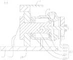
图1是本发明所述的一种涡轮壳摇臂焊接工装(装配有涡轮壳)的立体结构示意图;Fig. 1 is a three-dimensional schematic diagram of a turbine shell rocker arm welding tool (equipped with a turbine shell) according to the present invention;
图2是图1中a部分的放大图;Fig. 2 is an enlarged view of part a in Fig. 1;
图3是安装有旁通阀和摇臂的涡轮壳的结构示意图;FIG. 3 is a schematic structural diagram of a turbine casing with a bypass valve and a rocker arm installed;
图4是本发明所述的一种涡轮壳摇臂焊接工装(装配有涡轮壳)的主视图;4 is a front view of a turbine shell rocker arm welding tool (equipped with a turbine shell) according to the present invention;
图5是沿图4中A-A线的剖视图;Fig. 5 is a sectional view along line A-A in Fig. 4;
图6是沿图4中B-B线的剖视图(限位推杆位于非工作位置);FIG. 6 is a sectional view along the line B-B in FIG. 4 (the limit push rod is in the non-working position);
图7是本发明中限位推杆的结构示意图;Fig. 7 is the structural representation of the limit push rod in the present invention;
图8是本发明中限位挡片的结构示意图。FIG. 8 is a schematic view of the structure of the limiting block in the present invention.
附图标记说明:Description of reference numbers:
1.底板;11.提手;21.支撑竖板;22.定位座;221.定位轴;222.定位螺杆;223.定位压板;224.定位螺母;225.检测环;23.限位板;231.长部;232.短部;31.限位支座;32.限位推杆;321.限位压头;3211.凹口;322.导向轴;323.导向杆;324.导向弹簧;325.挡块;326.操纵杆;33.限位挡片;331.L型通孔;4.摇臂定位板;5.间隙板;7.旁通阀;8.摇臂;81.把手;9.涡轮壳;91.涡轮壳中孔;92.涡轮壳流道口。1. Bottom plate; 11. Handle; 21. Support vertical plate; 22. Positioning seat; 221. Positioning shaft; 222. Positioning screw; 223. Positioning pressure plate; 224. Positioning nut; 225. Detection ring; 23. Limit plate ; 231. Long part; 232. Short part; 31. Limit support; 32. Limit push rod; 321. Limit indenter; 3211. Notch; 322. Guide shaft; 323. Guide rod; 324. Guide Spring; 325. Stop; 326. Joystick; 33. Limiting plate; 331. L-shaped through hole; 4. Rocker arm positioning plate; 5. Gap plate; 7. Bypass valve; 8. Rocker arm; 81 .Handle; 9. Turbine casing; 91. Turbine casing hole; 92. Turbine casing runner opening.
具体实施方式Detailed ways
需要说明的是,在不冲突的情况下,本发明中的实施例及实施例中的特征可以相互组合。It should be noted that the embodiments of the present invention and the features of the embodiments may be combined with each other under the condition of no conflict.
下面将参考附图并结合实施例来详细说明本发明。The present invention will be described in detail below with reference to the accompanying drawings and in conjunction with the embodiments.
如图1-图8所示,一种涡轮壳摇臂焊接工装,包括底板1、涡轮壳固定机构、旁通阀限位机构和摇臂定位板4,涡轮壳固定机构包括固定在底板1上的支撑竖板21以及固定在支撑竖板21上的定位座22和限位板23;旁通阀限位机构包括固定在底板1上的限位支座31和与限位支座31滑动连接的限位推杆32,限位推杆32的端部具有用于控制旁通阀上下、左右运动的限位压头321;摇臂定位板4的一端设有定位孔;涡轮壳9经涡轮壳中孔91套设并固定在定位座22上,限位板23通过与涡轮壳流道口92的外侧壁之间的面面配合限制涡轮壳9旋转,推动限位推杆32至工作位置,使限位压头321压制旁通阀7,摇臂8的安装孔套设在衬套上,摇臂定位板4固定在支撑竖板21顶部,使定位孔套设在摇臂8的把手81上限位摇臂8的转动。As shown in Figures 1 to 8, a turbine shell rocker arm welding tool includes a bottom plate 1, a turbine shell fixing mechanism, a bypass valve limiting mechanism and a rocker
定位座22包括定位轴221、定位螺杆222、定位压板223和定位螺母224,定位轴221一端固定在支撑竖板21上,另一端与定位螺杆222固定连接;涡轮壳9经涡轮壳中孔91套设在定位轴221上,定位压板223套设在定位螺杆222上用于压制涡轮壳9,并通过定位螺母224与定位螺杆222的配合进行固定。The positioning
定位座22还包括检测环225,检测环225紧贴支撑竖板21套设在定位轴221上,用于检测涡轮壳9的口径是否合格。涡轮壳9成型后,可能有尺寸不合格的情况,将涡轮壳9一端套设在检测环225,即可发现涡轮壳9口径大小是否合格,可以省去一道检测工序,节约步骤,提高效率。The positioning
限位压头321为圆柱形结构,与旁通阀7接触一端具有凹口3211,凹口3211的方向与旁通阀7的倾斜方向一致,便于在压住旁通阀7的同时限制旁通阀7在上下、左右方向的摆动。凹口3211的设计可以有效地将旁通阀7固定住,避免旁通阀7发生摆动,影响焊接精度。The
限位支座31呈U型,限位推杆32依次穿过U型的限位支座31的两个侧壁与限位支座31滑动连接。The
限位推杆32还包括导向轴322、导向杆323、导向弹簧324、挡块325和操纵杆326,导向轴322依次穿过U型的限位支座31的两个侧壁与限位支座31滑动连接,导向轴322的一端具有盲孔一,导向杆323包括杆头和杆身,杆身依次穿过挡块325和导向弹簧324插入盲孔一内,限位压头321固定在挡块325上,固定端具有便于容纳杆头的盲孔二,盲孔一和盲孔二均具有便于导向杆323来回滑动的空间;旁通阀限位机构还包括固定在限位支座31顶部的限位挡片33,限位挡片33上设有L型通孔331,L型通孔331包括相互垂直的长孔和短孔,操纵杆326穿过L型通孔331设置在导向轴322上。沿长孔推动操纵杆326驱动限位压头321压制旁通阀7,然后将操纵杆326拨至短孔内,即可实现对限位压头321的固定。The
短孔向远离限位压头321一端延伸形成限位孔,所述限位孔用于避免操纵杆326进入短孔后再自动滑回长孔内。The short hole extends to one end away from the limiting
限位板23为L型,包括相互垂直的长部231和短部232,长部231通过与涡轮壳流道口92的外侧壁之间的面面配合限制涡轮壳9旋转,短部232便于将限位板23固定在支撑竖板21上。The limiting
底板1上设有提手11,便于搬运工装。A
焊接工装还包括间隙板5,间隙板5放置在摇臂8与涡轮壳9之间,用于调整焊接间隙。在不使用间隙板5的情况下,可以将间隙板5固定在支撑竖板21上,避免间隙板5在搬运工装过程中丢失。The welding tool further includes a
安装过程中,先通过涡轮壳中孔91将涡轮壳9套设在定位座22上,并进行规定,限位板23与涡轮壳流道口92的外侧壁之间实现面面配合,从而避免涡轮壳9旋转,实现对涡轮壳9的牢固固定,然后推动限位推杆32至工作位置,使限位压头321压制旁通阀7,避免旁通阀7发生上下、左右摆动,确保后续的焊接精度;然后将摇臂8的安装孔套设在旁通阀7顶部的衬套上,再将摇臂定位板4固定在支撑竖板21顶部,使定位孔套设在摇臂8的把手81上,从而实现对摇臂8角度的确定。During the installation process, first set the turbine shell 9 on the
可以在U型限位支座31两个侧壁的顶部设置半圆形通孔,并设置两个具有半圆形通孔的压块,将导向轴322放入U型限位支座31两个侧壁顶部的半圆形通孔后,压设两个具有半圆形通孔的压块并固定,完成导向轴322的安装。Semi-circular through holes can be provided at the top of the two side walls of the
本发明先通过定位座22和限位板23将涡轮壳进行固定,再通过限位压头321压制旁通阀7,避免旁通阀7发生上下、左右方向的摆动,并通过摇臂定位板4确定摇臂8的角度,最终进行精准的焊接,安装过程简单,效率高。In the present invention, the turbine casing is first fixed by the positioning
以上所述仅为本发明的较佳实施例而已,并不用以限制本发明,凡在本发明的精神和原则之内,所作的任何修改、等同替换、改进等,均应包含在本发明的保护范围之内。The above descriptions are only preferred embodiments of the present invention, and are not intended to limit the present invention. Any modification, equivalent replacement, improvement, etc. made within the spirit and principle of the present invention shall be included in the scope of the present invention. within the scope of protection.
Claims (10)
Priority Applications (2)
| Application Number | Priority Date | Filing Date | Title |
|---|---|---|---|
| CN201911367215.6ACN111112912B (en) | 2019-12-26 | 2019-12-26 | A kind of turbine shell rocker arm welding tool |
| PCT/CN2020/091154WO2021128717A1 (en) | 2019-12-26 | 2020-05-20 | Welding fixture for turbine housing rocker arm |
Applications Claiming Priority (1)
| Application Number | Priority Date | Filing Date | Title |
|---|---|---|---|
| CN201911367215.6ACN111112912B (en) | 2019-12-26 | 2019-12-26 | A kind of turbine shell rocker arm welding tool |
Publications (2)
| Publication Number | Publication Date |
|---|---|
| CN111112912A CN111112912A (en) | 2020-05-08 |
| CN111112912Btrue CN111112912B (en) | 2020-12-18 |
Family
ID=70503177
Family Applications (1)
| Application Number | Title | Priority Date | Filing Date |
|---|---|---|---|
| CN201911367215.6AActiveCN111112912B (en) | 2019-12-26 | 2019-12-26 | A kind of turbine shell rocker arm welding tool |
Country Status (2)
| Country | Link |
|---|---|
| CN (1) | CN111112912B (en) |
| WO (1) | WO2021128717A1 (en) |
Families Citing this family (7)
| Publication number | Priority date | Publication date | Assignee | Title |
|---|---|---|---|---|
| CN111112912B (en)* | 2019-12-26 | 2020-12-18 | 常州机电职业技术学院 | A kind of turbine shell rocker arm welding tool |
| CN111558764A (en)* | 2020-05-22 | 2020-08-21 | 株洲天一自动焊接装备有限公司 | Turbine shell rocker arm welding method |
| CN112091476B (en)* | 2020-09-29 | 2024-08-06 | 江阴机械制造有限公司 | Welding wire for welding turbine shell waste discharge valve, welding process and welding tool |
| CN112355465B (en)* | 2020-11-03 | 2022-08-09 | 广州松兴电气股份有限公司 | Turbocharger rotating shaft and crank automatic positioning tool |
| CN113001087A (en)* | 2021-03-30 | 2021-06-22 | 无锡烨隆精密机械股份有限公司 | Turbine shell welding pre-clamping device |
| CN114211281A (en)* | 2021-12-23 | 2022-03-22 | 阿路米(无锡)有限公司 | Compressor casing processing frock |
| CN116423132B (en)* | 2023-04-28 | 2023-09-22 | 浙江巨峰汽车零部件有限公司 | Automatic welding equipment of turbocharger |
Citations (8)
| Publication number | Priority date | Publication date | Assignee | Title |
|---|---|---|---|---|
| JP2013013921A (en)* | 2011-07-05 | 2013-01-24 | Hitachi Ltd | Automatic welding system and automatic welding method |
| CN202780354U (en)* | 2012-09-28 | 2013-03-13 | 常州南车汽车零部件有限公司 | Adjustable welding fixture of turbocharger shell |
| CN205363109U (en)* | 2016-01-22 | 2016-07-06 | 南阳飞龙汽车零部件有限公司 | Turbine volute automatic weld positioner |
| CN207840538U (en)* | 2018-01-30 | 2018-09-11 | 苏州泰因姆自动化系统有限公司 | Turbine case rocking arm welding equipment |
| CN209223487U (en)* | 2018-12-19 | 2019-08-09 | 无锡联睿科技有限公司 | A kind of turbine case rocker arm welding floating hold-down mechanism |
| CN209465870U (en)* | 2018-12-26 | 2019-10-08 | 江苏泽茗精密机械制造股份有限公司 | The valve rocker arm assembly welding tooling of turbine case |
| CN209578470U (en)* | 2018-11-27 | 2019-11-05 | 高铭科维科技无锡有限公司 | Turbocharging shell clamping device |
| CN209578533U (en)* | 2018-12-27 | 2019-11-05 | 高铭科维科技无锡有限公司 | Turbocharging shell Automatic-clamping and assembly device |
Family Cites Families (1)
| Publication number | Priority date | Publication date | Assignee | Title |
|---|---|---|---|---|
| CN111112912B (en)* | 2019-12-26 | 2020-12-18 | 常州机电职业技术学院 | A kind of turbine shell rocker arm welding tool |
- 2019
- 2019-12-26CNCN201911367215.6Apatent/CN111112912B/enactiveActive
- 2020
- 2020-05-20WOPCT/CN2020/091154patent/WO2021128717A1/ennot_activeCeased
Patent Citations (8)
| Publication number | Priority date | Publication date | Assignee | Title |
|---|---|---|---|---|
| JP2013013921A (en)* | 2011-07-05 | 2013-01-24 | Hitachi Ltd | Automatic welding system and automatic welding method |
| CN202780354U (en)* | 2012-09-28 | 2013-03-13 | 常州南车汽车零部件有限公司 | Adjustable welding fixture of turbocharger shell |
| CN205363109U (en)* | 2016-01-22 | 2016-07-06 | 南阳飞龙汽车零部件有限公司 | Turbine volute automatic weld positioner |
| CN207840538U (en)* | 2018-01-30 | 2018-09-11 | 苏州泰因姆自动化系统有限公司 | Turbine case rocking arm welding equipment |
| CN209578470U (en)* | 2018-11-27 | 2019-11-05 | 高铭科维科技无锡有限公司 | Turbocharging shell clamping device |
| CN209223487U (en)* | 2018-12-19 | 2019-08-09 | 无锡联睿科技有限公司 | A kind of turbine case rocker arm welding floating hold-down mechanism |
| CN209465870U (en)* | 2018-12-26 | 2019-10-08 | 江苏泽茗精密机械制造股份有限公司 | The valve rocker arm assembly welding tooling of turbine case |
| CN209578533U (en)* | 2018-12-27 | 2019-11-05 | 高铭科维科技无锡有限公司 | Turbocharging shell Automatic-clamping and assembly device |
Also Published As
| Publication number | Publication date |
|---|---|
| CN111112912A (en) | 2020-05-08 |
| WO2021128717A1 (en) | 2021-07-01 |
Similar Documents
| Publication | Publication Date | Title |
|---|---|---|
| CN111112912B (en) | A kind of turbine shell rocker arm welding tool | |
| CN108746726A (en) | Aero-engine air inlet guide vane and rocker arm composition drilling equipment and application method | |
| CN202002627U (en) | Measuring device of engine valve lift | |
| CN202002602U (en) | Detecting device of cam shaft runout amount | |
| CN212858365U (en) | Rocker arm welding clamp for turbine shell production | |
| CN106514548A (en) | Press fitting tool for crankshaft rear oil seal | |
| CN206208174U (en) | Engine valve and piston dynamic clearance survey tool | |
| CN109916359B (en) | Device for measuring axial clearance of bearing | |
| CN105910811A (en) | Cam tappet wearing test device | |
| CN210209309U (en) | Automatic press fitting device for pins | |
| WO2019056480A1 (en) | DEVICE FOR DETECTING THE ABSENCE OF CHAIN PORTION | |
| CN203171312U (en) | Clamping mechanism of manipulator | |
| WO2025123538A1 (en) | Method for measuring precision of regulating valve | |
| CN222868721U (en) | Turnover shifting mechanism | |
| CN208820591U (en) | The bearing mounting mechanism of motor | |
| CN210719707U (en) | Engine fuel-saving testing device | |
| CN207439288U (en) | A kind of cubing of air valve of motor cycle rocking arm | |
| CN208104499U (en) | Fast-positioning device in small dimension billet heating furnace | |
| CN101476984A (en) | Air valve pressing mechanism capable of precisely controlling different air valve angle shift-down | |
| CN220835691U (en) | Test tube rack propulsion mechanism and sample analyzer | |
| CN212004486U (en) | A valve control structure | |
| CN218407587U (en) | Detection device for automobile exhaust gas | |
| CN220751616U (en) | Valve quality inspection tool | |
| CN211737237U (en) | Variable valve lift apparatus of engine | |
| CN219180775U (en) | Automatic rotating device for polarization of laboratory antenna |
Legal Events
| Date | Code | Title | Description |
|---|---|---|---|
| PB01 | Publication | ||
| PB01 | Publication | ||
| SE01 | Entry into force of request for substantive examination | ||
| SE01 | Entry into force of request for substantive examination | ||
| GR01 | Patent grant | ||
| GR01 | Patent grant |