CN111110233B - Multi-interface flexible electrode - Google Patents
Multi-interface flexible electrodeDownload PDFInfo
- Publication number
- CN111110233B CN111110233BCN201911350764.2ACN201911350764ACN111110233BCN 111110233 BCN111110233 BCN 111110233BCN 201911350764 ACN201911350764 ACN 201911350764ACN 111110233 BCN111110233 BCN 111110233B
- Authority
- CN
- China
- Prior art keywords
- layer
- conductive
- flexible substrate
- flexible
- conductive layer
- Prior art date
- Legal status (The legal status is an assumption and is not a legal conclusion. Google has not performed a legal analysis and makes no representation as to the accuracy of the status listed.)
- Active
Links
Images


Classifications
- A—HUMAN NECESSITIES
- A61—MEDICAL OR VETERINARY SCIENCE; HYGIENE
- A61B—DIAGNOSIS; SURGERY; IDENTIFICATION
- A61B5/00—Measuring for diagnostic purposes; Identification of persons
- A61B5/24—Detecting, measuring or recording bioelectric or biomagnetic signals of the body or parts thereof
- A61B5/25—Bioelectric electrodes therefor
- A61B5/279—Bioelectric electrodes therefor specially adapted for particular uses
- A61B5/296—Bioelectric electrodes therefor specially adapted for particular uses for electromyography [EMG]
- H—ELECTRICITY
- H01—ELECTRIC ELEMENTS
- H01R—ELECTRICALLY-CONDUCTIVE CONNECTIONS; STRUCTURAL ASSOCIATIONS OF A PLURALITY OF MUTUALLY-INSULATED ELECTRICAL CONNECTING ELEMENTS; COUPLING DEVICES; CURRENT COLLECTORS
- H01R13/00—Details of coupling devices of the kinds covered by groups H01R12/70 or H01R24/00 - H01R33/00
- H01R13/66—Structural association with built-in electrical component
- H01R13/665—Structural association with built-in electrical component with built-in electronic circuit
- H01R13/6683—Structural association with built-in electrical component with built-in electronic circuit with built-in sensor
Landscapes
- Engineering & Computer Science (AREA)
- Health & Medical Sciences (AREA)
- Life Sciences & Earth Sciences (AREA)
- Microelectronics & Electronic Packaging (AREA)
- Medical Informatics (AREA)
- Pathology (AREA)
- Biomedical Technology (AREA)
- Heart & Thoracic Surgery (AREA)
- Physics & Mathematics (AREA)
- Molecular Biology (AREA)
- Surgery (AREA)
- Animal Behavior & Ethology (AREA)
- General Health & Medical Sciences (AREA)
- Public Health (AREA)
- Veterinary Medicine (AREA)
- Biophysics (AREA)
- Structure Of Printed Boards (AREA)
Abstract
Description
Translated fromChinese技术领域technical field
本发明涉及生物医学技术领域,特别涉及一种多接口的柔性电极。The invention relates to the technical field of biomedicine, in particular to a flexible electrode with multiple interfaces.
背景技术Background technique
柔性电极是一种自身具备柔性,能很好地被贴于被测表面,并能随表面的形变而变形,同时器件仍能正常工作的一种电极。它常被贴于人体体表各部位,并能紧贴皮肤,同时,通过使用柔性材料及设计柔性结构,电极具备在保持电极性能的同时能随表皮变形而大范围延展变形的性能,即具备很好的柔性。A flexible electrode is a kind of electrode that is flexible by itself, can be well attached to the surface to be measured, and can deform with the deformation of the surface, while the device can still work normally. It is often attached to various parts of the human body surface and can be close to the skin. At the same time, by using flexible materials and designing a flexible structure, the electrode has the performance of maintaining the performance of the electrode and can be extended and deformed in a large range with the deformation of the epidermis, that is, it has the Very flexible.
柔性电极相比于传统电极具有厚度薄、体积小、对表皮无损伤等特点,能方便测得体表狭小或曲率大的区域的生理信号,这些生理信号包括肌电信号、心电信号和脑电信号等。随着人们对体表生理信号研究的深入,需要采集更为丰富的生理信号,如多部位、空间分布的生理信号,为此有必要在一块被测区域内设置多个信号采集电极。同时,当检测不同位置的肌电分布信号时,由于肌肉群的大小和分布不同,为使电极位置与肌肉位置相匹配,就需设计电极分布位置不同的阵列电极,这加大了柔性电极的制作成本。Compared with traditional electrodes, flexible electrodes have the characteristics of thin thickness, small size, and no damage to the epidermis. They can easily measure physiological signals in areas with small or large curvature of the body surface. These physiological signals include EMG, ECG and EEG. signal etc. With the in-depth study of physiological signals on the body surface, it is necessary to collect more abundant physiological signals, such as physiological signals in multiple parts and spatial distribution. Therefore, it is necessary to set up multiple signal acquisition electrodes in a measured area. At the same time, when detecting EMG distribution signals at different positions, due to the different size and distribution of muscle groups, in order to match the electrode positions with the muscle positions, it is necessary to design array electrodes with different electrode distribution positions, which increases the flexibility of the flexible electrodes. cost of production.
发明内容SUMMARY OF THE INVENTION
有鉴于此,本发明提供一种多接口的柔性电极,信号采集模块的第二导电部可与接线模块上的任意第一导电部接触,提高了电极布置的灵活性,降低了电极制备成本。In view of this, the present invention provides a flexible electrode with multiple interfaces. The second conductive part of the signal acquisition module can contact any first conductive part on the wiring module, which improves the flexibility of electrode arrangement and reduces the cost of electrode preparation.
一种多接口的柔性电极,包括接线模块和至少一个信号采集模块,接线模块包括第一柔性基底和设置在第一柔性基底上的多个第一导电部及多根分别与各第一导电部连接的第一导线,信号采集模块包括第二柔性基底和设置在第二柔性基底上的第二导电部、电极片和第二导线,第二导线的两端分别连接于第二导电部与电极片,第二柔性基底可拆装地设置在第一柔性基底上,第二导电部与第一导电部接触。A multi-interface flexible electrode, comprising a wiring module and at least one signal acquisition module, the wiring module comprises a first flexible substrate, a plurality of first conductive parts arranged on the first flexible substrate, and a plurality of first conductive parts respectively connected to the first conductive parts The connected first wire, the signal acquisition module includes a second flexible base, a second conductive part, an electrode sheet and a second wire arranged on the second flexible base, and the two ends of the second wire are respectively connected to the second conductive part and the electrode The second flexible substrate is detachably disposed on the first flexible substrate, and the second conductive portion is in contact with the first conductive portion.
在本发明的实施例中,上述第一柔性基底包括相对的第一表面和第二表面,各所述第一导电部和各所述第一导线设置在所述第一表面上,所述第二表面设有第一粘胶层,所述第一表面上划分有布线区和接口区,所述布线区位于所述第一表面的中部,所述接口区沿着所述布线区的周向设置,各所述第一导电部设置在所述接口区内,各所述第一导线设置在所述布线区内。In an embodiment of the present invention, the first flexible substrate includes a first surface and a second surface opposite to each other, each of the first conductive parts and each of the first wires are disposed on the first surface, and the first Two surfaces are provided with a first adhesive layer, the first surface is divided into a wiring area and an interface area, the wiring area is located in the middle of the first surface, and the interface area is along the circumference of the wiring area Each of the first conductive parts is arranged in the interface area, and each of the first wires is arranged in the wiring area.
在本发明的实施例中,上述接线模块还包括覆盖膜,所述覆盖膜覆盖所述布线区和所述接口区,所述覆盖膜的中部设有第二粘胶层,所述覆盖膜通过所述第二粘胶层粘在所述布线区上,所述覆盖膜与所述接口区上下相对设置,当所述第二导电部与所述第一导电部接触时,所述第二柔性基底的一端位于所述覆盖膜的下方。In an embodiment of the present invention, the above-mentioned wiring module further includes a cover film, the cover film covers the wiring area and the interface area, a second adhesive layer is provided in the middle of the cover film, and the cover film passes through The second adhesive layer is adhered on the wiring area, the cover film is arranged opposite to the interface area up and down, when the second conductive part is in contact with the first conductive part, the second flexible One end of the substrate is located below the cover film.
在本发明的实施例中,上述第二柔性基底包括相对的第三表面和第四表面,所述第二导电部、所述电极片和所述第二导线设置在所述第三表面上,所述第三表面设有第三粘胶层,所述第二柔性基底通过所述第三粘胶层可拆装地粘在所述第一柔性基底的所述第一表面上。In an embodiment of the present invention, the above-mentioned second flexible substrate includes a third surface and a fourth surface opposite to each other, and the second conductive part, the electrode sheet and the second wire are arranged on the third surface, The third surface is provided with a third adhesive layer, and the second flexible substrate is detachably adhered to the first surface of the first flexible substrate through the third adhesive layer.
在本发明的实施例中,上述第二柔性基底包括第一承载部和第二承载部,所述第一承载部的一端连接于所述第二承载部,所述第一承载部的宽度小于所述第二承载部的宽度,所述第二导电部设置在所述第一承载部上,所述电极片设置在所述第二承载部上。In an embodiment of the present invention, the second flexible substrate includes a first bearing portion and a second bearing portion, one end of the first bearing portion is connected to the second bearing portion, and the width of the first bearing portion is smaller than The width of the second carrying portion, the second conductive portion is disposed on the first carrying portion, and the electrode sheet is disposed on the second carrying portion.
在本发明的实施例中,上述第一导线包括延展段及与所述延展段连接的引出段,所述延展段和所述第二导线呈蛇形,所述引出段用以输出电信号。In an embodiment of the present invention, the first wire includes an extension section and a lead-out section connected to the extension section, the extension section and the second wire are serpentine, and the lead-out section is used for outputting electrical signals.
在本发明的实施例中,上述第一导电部和所述第二导电部呈圆形。In an embodiment of the present invention, the first conductive portion and the second conductive portion are circular.
在本发明的实施例中,上述第一导电部包括第一垫片层和第一导电层,所述第一垫片层设置在所述第一柔性基底上,所述第一导电层设置在所述第一垫片层上;In an embodiment of the present invention, the first conductive portion includes a first pad layer and a first conductive layer, the first pad layer is provided on the first flexible substrate, and the first conductive layer is provided on the on the first gasket layer;
所述第一导线包括第二垫片层、第二导电层和第一保护层,所述第二垫片层设置在所述第一柔性基底上,所述第二导电层设置在所述第二垫片层上,所述第一保护层覆盖在所述第二导电层上,所述第一垫片层与所述第二垫片层连接,所述第一导电层与所述第二导电层电性连接。The first wire includes a second pad layer, a second conductive layer and a first protective layer, the second pad layer is arranged on the first flexible substrate, and the second conductive layer is arranged on the first flexible substrate. On two spacer layers, the first protective layer covers the second conductive layer, the first spacer layer is connected to the second spacer layer, and the first conductive layer is connected to the second spacer layer. The conductive layer is electrically connected.
在本发明的实施例中,上述第二导电部包括第三垫片层和第三导电层,所述第三垫片层设置在所述第二柔性基底上,所述第三导电层设置在所述第三垫片层上;In an embodiment of the present invention, the second conductive part includes a third spacer layer and a third conductive layer, the third spacer layer is disposed on the second flexible substrate, and the third conductive layer is disposed on on the third gasket layer;
所述第二导线包括第四垫片层、第四导电层和第二保护层,所述第四垫片层设置在所述第二柔性基底上,所述第四导电层设置在所述第四垫片层上,所述第二保护层覆盖在所述第四导电层上,所述第四垫片层与所述第三垫片层连接,所述第四导电层与所述第三导电层电性连接;The second wire includes a fourth pad layer, a fourth conductive layer and a second protection layer, the fourth pad layer is arranged on the second flexible substrate, and the fourth conductive layer is arranged on the first On four spacer layers, the second protective layer covers the fourth conductive layer, the fourth spacer layer is connected to the third spacer layer, and the fourth conductive layer is connected to the third spacer layer. The conductive layer is electrically connected;
所述电极片包括第五垫片层和第五导电层,所述第五垫片层设置在所述第二柔性基底上,所述第五导电层设置在所述第五垫片层上,所述第五垫片层与所述第四垫片层连接,所述第五导电层与所述第四导电层电性连接。The electrode sheet includes a fifth spacer layer and a fifth conductive layer, the fifth spacer layer is disposed on the second flexible substrate, and the fifth conductive layer is disposed on the fifth spacer layer, The fifth pad layer is connected to the fourth pad layer, and the fifth conductive layer is electrically connected to the fourth conductive layer.
在本发明的实施例中,上述第一导电层、所述第二导电层、所述第三导电层、所述第四导电层和所述第五导电层均包括第一金属层和第二金属层,所述第一金属层与所述第二金属层采用不同金属材料制成,所述第一金属层与所述第二金属层层叠设置。In an embodiment of the present invention, the first conductive layer, the second conductive layer, the third conductive layer, the fourth conductive layer, and the fifth conductive layer all include a first metal layer and a second conductive layer. A metal layer, the first metal layer and the second metal layer are made of different metal materials, and the first metal layer and the second metal layer are stacked.
本发明的多接口的柔性电极的信号采集模块与接线模块分离设计,信号采集模块的第二导电部可与接线模块上的任意第一导电部接触,信号采集模块的数量、大小,以及信号采集模块连接在接线模块上的位置,信号采集模块之间的间距、位置和角度等,均可根据实际需要自由选择,提高了信号采集模块布置的灵活性,降低了柔性电极的制备成本。The signal acquisition module of the multi-interface flexible electrode of the present invention is designed separately from the wiring module, the second conductive part of the signal acquisition module can be in contact with any first conductive part on the wiring module, the number and size of the signal acquisition modules, and the signal acquisition The position where the module is connected to the wiring module, the spacing, position and angle between the signal acquisition modules can be freely selected according to actual needs, which improves the flexibility of the arrangement of the signal acquisition modules and reduces the preparation cost of flexible electrodes.
附图说明Description of drawings
图1是本发明的多接口的柔性电极的结构示意图。FIG. 1 is a schematic structural diagram of a multi-interface flexible electrode of the present invention.
图2是本发明的接线模块与信号采集模块连接时的局部剖视示意图。FIG. 2 is a partial cross-sectional schematic diagram of the connection module of the present invention when the signal acquisition module is connected.
图3是本发明的第一导电部的剖视结构示意图。3 is a schematic cross-sectional structural diagram of the first conductive portion of the present invention.
图4是本发明的第一导线的剖视结构示意图。FIG. 4 is a schematic cross-sectional view of the first wire of the present invention.
图5是本发明的第二导电部的剖视结构示意图。FIG. 5 is a schematic cross-sectional structural diagram of the second conductive portion of the present invention.
图6是本发明的第二导线的剖视结构示意图。FIG. 6 is a schematic cross-sectional view of the second wire of the present invention.
图7是本发明的电极片的剖视结构示意图。FIG. 7 is a schematic cross-sectional structure diagram of the electrode sheet of the present invention.
具体实施方式Detailed ways
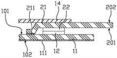
图1是本发明的多接口的柔性电极的结构示意图,图2是本发明的接线模块与信号采集模块连接时的局部剖视示意图,如图1和图2所示,多接口的柔性电极包括接线模块10和至少一个信号采集模块20,接线模块10包括第一柔性基底11和设置在第一柔性基底11上的多个第一导电部12及多根分别与各第一导电部12连接的第一导线13,信号采集模块20包括第二柔性基底21和设置在第二柔性基底21上的第二导电部22、第二导线23和电极片24,第二导线23的两端分别连接于第二导电部22与电极片24,第二柔性基底21可拆装地设置在第一柔性基底11上,第二导电部22与第一导电部12接触。在本实施例中,信号采集模块20与接线模块10分离设计,信号采集模块20的第二导电部22可与接线模块10上的任意第一导电部12接触,信号采集模块20的数量、大小,以及信号采集模块20连接在接线模块10上的位置,信号采集模块20之间的间距、位置和角度等,均可根据实际需要自由选择,提高了信号采集模块20布置的灵活性,降低了柔性电极的制备成本;而且,信号采集模块20的数量以及信号采集模块20连接在接线模块10上的位置、信号采集模块20之间的间距、位置和角度可根据实际需要自由选择;此外,当需要改变信号采集模块20的电极片24大小和结构时,只需更改单个信号采集模块20的电极片24即可,无需重新制作整套多接口的柔性电极,提高了便利度,进一步降低了成本。FIG. 1 is a schematic structural diagram of a multi-interface flexible electrode of the present invention, and FIG. 2 is a partial cross-sectional schematic diagram of the connection module of the present invention being connected to a signal acquisition module. As shown in FIGS. 1 and 2 , the multi-interface flexible electrode includes The
进一步地,如图1和图2所示,第一柔性基底11包括相对的第一表面101和第二表面102,各第一导电部12和各第一导线13设置在第一表面101上,第二表面102设有第一粘胶层111,第一表面101上划分有布线区101a和接口区101b,布线区101a位于第一表面101的中部,接口区101b沿着布线区101a的周向设置(接口区101b靠近第一柔性基底11的外侧区域),各第一导电部12设置在接口区101b内,各第一导线13设置在布线区101a内。Further, as shown in FIG. 1 and FIG. 2 , the first
进一步地,如图2所示,接线模块10还包括覆盖膜14,覆盖膜14覆盖布线区101a和接口区101b,覆盖膜14的中部设有第二粘胶层141,覆盖膜14通过第二粘胶层141粘在布线区101a上,覆盖膜14与接口区101b上下相对设置,当第二导电部22与第一导电部12接触时,第二柔性基底21的一端位于覆盖膜14的下方。在本实施例中,覆盖膜14覆盖布线区101a和接口区101b,保护其他未被连接的第一导电部12和第一导线13。Further, as shown in FIG. 2 , the
进一步地,如图1和图2所示,第二柔性基底21包括相对的第三表面201和第四表面202,第二导电部22、第二导线23和电极片24设置在第三表面201上,第三表面201设有第三粘胶层211,第二柔性基底21通过第三粘胶层211可拆装地粘在第一柔性基底11的第一表面101上。Further, as shown in FIG. 1 and FIG. 2 , the second
进一步地,如图1所示,第二柔性基底21包括第一承载部21a和第二承载部21b,第一承载部21a的一端连接于第二承载部21b,第一承载部21a的宽度小于第二承载部21b的宽度,第二导电部22设置在第一承载部21a上,电极片24设置在第二承载部21b上。当信号采集模块20连接在接线模块10上时,第一承载部21a上的第三粘胶层211粘在第一柔性基底11上,第二承载部21b伸出第一柔性基底11外,并粘贴在皮肤上。Further, as shown in FIG. 1 , the second
进一步地,第一导线13包括延展段13a及与延展段13a连接的引出段13b,延展段13a和第二导线23呈蛇形,引出段13b用以输出电信号。延展段13a在第一柔性基底11出现挤压、弯折、变形时可延展变形,避免应力集中造成的断线;第二导线23在第二柔性基底21出现挤压、弯折、变形时可延展变形,避免应力集中造成的断线。在本实施例中,引出段13b为直线型,引出段13b通过异性导电膜(ACF)与信号处理装置电性连接。Further, the
进一步地,如图1所示,第一导电部12和第二导电部22呈圆形,使信号采集模块20可以调整连接角度,方便电极片24与不同肌肉进行匹配。Further, as shown in FIG. 1 , the first
进一步地,第一导电部12的截面面积大于或等于第二导电部22的截面面积,第一导电部12和第二导电部22的直径为2mm-5mm,但并不以此为限。Further, the cross-sectional area of the first
进一步地,如图1所示,电极片24为矩形结构,边长为4mm~10mm,但并不以此为限。Further, as shown in FIG. 1 , the
进一步地,图3是本发明的第一导电部的剖视结构示意图,图4是本发明的第一导线的剖视结构示意图,如图3和图4所示,第一导电部12包括第一垫片层121和第一导电层122,第一垫片层121设置在第一柔性基底11上,第一导电层122设置在第一垫片层121上;第一导线13包括第二垫片层131、第二导电层132和第一保护层133,第二垫片层131设置在第一柔性基底11上,第二导电层132设置在第二垫片层131上,第一保护层133覆盖在第二导电层132上,第一垫片层121与第二垫片层131连接,第一导电层122与第二导电层132电性连接。Further, FIG. 3 is a schematic cross-sectional structural diagram of the first conductive portion of the present invention, and FIG. 4 is a cross-sectional structural schematic diagram of the first wire of the present invention. As shown in FIGS. 3 and 4 , the first
进一步地,第一垫片层121和第一导电层122的形状相同,即均呈圆形;第二垫片层131、第二导电层132和第一保护层133的形状相同,即均呈蛇形。Further, the shapes of the
进一步地,第一垫片层121和第二垫片层131采用同种材料一体成型,例如聚酰亚胺材料。Further, the
进一步地,第一导电层122和第二导电层132采用同种材料一体成型。在本实施例中,第一导电层122和第二导电层132均包括第一金属层和第二金属层,第一金属层与第二金属层采用不同金属材料制成,例如第一金属层采用铬材料制成,第二金属层采用金材料制成,第一金属层与第二金属层层叠设置,第二金属层设置在第一金属层上。Further, the first
进一步地,第一保护层133采用聚酰亚胺材料制成。Further, the first
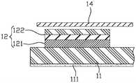
进一步地,图5是本发明的第二导电部的剖视结构示意图,图6是本发明的第二导线的剖视结构示意图,图7是本发明的电极片的剖视结构示意图,如图5、图6和图7所示,第二导电部22包括第三垫片层221和第三导电层222,第三垫片层221设置在第二柔性基底21上,第三导电层222设置在第三垫片层221上;Further, FIG. 5 is a cross-sectional structural schematic diagram of the second conductive portion of the present invention, FIG. 6 is a cross-sectional structural schematic diagram of the second wire of the present invention, and FIG. 7 is a cross-sectional structural schematic diagram of an electrode sheet of the present invention, as shown in FIG. 5. As shown in FIG. 6 and FIG. 7 , the second
第二导线23包括第四垫片层231、第四导电层232和第二保护层233,第四垫片层231设置在第二柔性基底21上,第四导电层232设置在第四垫片层231上,第二保护层233覆盖在第四导电层232上,第四垫片层231与第三垫片层221连接,第四导电层232与第三导电层222电性连接;The
电极片24包括第五垫片层241和第五导电层242,第五垫片层241设置在第二柔性基底21上,第五导电层242设置在第五垫片层241上,第五垫片层241与第四垫片层231连接,第五导电层242与第四导电层232电性连接。The
进一步地,第三垫片层221和第三导电层222的形状相同,即均呈圆形;第四垫片层231、第四导电层232和第二保护层233的形状相同,即均呈蛇形;第五垫片层241和第五导电层242的形状相同,即均呈矩形。Further, the shapes of the
进一步地,第三垫片层221、第四垫片层231和第五垫片层241采用同种材料一体成型,例如聚酰亚胺材料。Further, the
进一步地,第三导电层222、第四导电层232和第五导电层242采用同种材料一体成型。在本实施例中,第三导电层222、第四导电层232和第五导电层242均包括第一金属层和第二金属层,第一金属层与第二金属层采用不同金属材料制成,例如第一金属层采用铬材料制成,第二金属层采用金材料制成,第一金属层与第二金属层层叠设置,第二金属层设置在第一金属层上。Further, the third
进一步地,第二保护层233采用聚酰亚胺材料制成。Further, the second
如图1和图2所示,利用多接口的柔性电极采集生理信号的具体步骤包括:As shown in Figure 1 and Figure 2, the specific steps for collecting physiological signals using flexible electrodes with multiple interfaces include:
首先将接线模块10贴于皮肤表面;First, the
再将一个信号采集模块20的第二导电部22朝下与接线模块10上的第一导电部12对准,并将信号采集模块20的第二柔性基底21粘在接线模块10的第一柔性基底11上,使第一导电部12和第二导电部22保持紧密相连;Then, align the second
当需要将信号采集模块20与接线模块10分离时,仅需将信号采集模块20的第二柔性基底21外围粘在第一柔性基底11的部分撕起即可,由于第二柔性基底21具备粘性的面积较小,将其与第一柔性基底11分离时较为容易,不会影响第一柔性基底11与皮肤的粘连性。When the
第一柔性基底11、第二柔性基底21和覆盖膜14上使用薄的单面粘性材料,且可多次粘连,如敷料,保证多次粘连和撕起,同时使接线模块10与信号采集模块20与皮肤紧紧粘连。The first
值得一提的是,利用本发明的多接口的柔性电极与商业肌电信号采集仪进行了对比测试,根据测试结果显示,肌电信号基本一致,对应的肌电指标值也基本相同,验证了本发明的多接口的柔性电极采集到的肌电信号的准确性及可性靠。It is worth mentioning that the multi-interface flexible electrode of the present invention is used to conduct a comparative test with a commercial EMG signal acquisition instrument. According to the test results, the EMG signals are basically the same, and the corresponding EMG index values are basically the same. The accuracy and reliability of the electromyographic signals collected by the multi-interface flexible electrode of the present invention are reliable.
本发明并不限于上述实施方式中的具体细节,在本发明的技术构思范围内,可以对本发明的技术方案进行多种简单变型,这些简单变型均属于本发明的保护范围。在上述具体实施方式中所描述的各个具体技术特征,在不矛盾的情况下,可以通过任何合适的方式进行组合。为了避免不必要的重复,本发明对各种可能的组合方式不再另行说明。The present invention is not limited to the specific details in the above-mentioned embodiments, and within the scope of the technical concept of the present invention, various simple modifications can be made to the technical solutions of the present invention, and these simple modifications all belong to the protection scope of the present invention. The various specific technical features described in the above-mentioned specific embodiments may be combined in any suitable manner under the condition of no contradiction. In order to avoid unnecessary repetition, the present invention will not describe various possible combinations.
Claims (10)
Translated fromChinesePriority Applications (1)
| Application Number | Priority Date | Filing Date | Title |
|---|---|---|---|
| CN201911350764.2ACN111110233B (en) | 2019-12-24 | 2019-12-24 | Multi-interface flexible electrode |
Applications Claiming Priority (1)
| Application Number | Priority Date | Filing Date | Title |
|---|---|---|---|
| CN201911350764.2ACN111110233B (en) | 2019-12-24 | 2019-12-24 | Multi-interface flexible electrode |
Publications (2)
| Publication Number | Publication Date |
|---|---|
| CN111110233A CN111110233A (en) | 2020-05-08 |
| CN111110233Btrue CN111110233B (en) | 2022-10-11 |
Family
ID=70502096
Family Applications (1)
| Application Number | Title | Priority Date | Filing Date |
|---|---|---|---|
| CN201911350764.2AActiveCN111110233B (en) | 2019-12-24 | 2019-12-24 | Multi-interface flexible electrode |
Country Status (1)
| Country | Link |
|---|---|
| CN (1) | CN111110233B (en) |
Families Citing this family (1)
| Publication number | Priority date | Publication date | Assignee | Title |
|---|---|---|---|---|
| CN120393288A (en)* | 2020-08-28 | 2025-08-01 | 江苏海莱新创医疗科技有限公司 | Wearable electric field application device |
Citations (8)
| Publication number | Priority date | Publication date | Assignee | Title |
|---|---|---|---|---|
| CN101321494A (en)* | 2005-11-30 | 2008-12-10 | 皇家飞利浦电子股份有限公司 | Electro-mechanical connector for thin medical monitoring patch |
| CN107374625A (en)* | 2017-06-19 | 2017-11-24 | 上海大学 | Active dot matrix formula flexible electrode label apparatus |
| CN108606788A (en)* | 2018-05-03 | 2018-10-02 | 清华大学 | Flexible patch |
| CN109416266A (en)* | 2016-06-20 | 2019-03-01 | 皇家飞利浦有限公司 | Medical coupling unit and sensor side connector |
| CN109616449A (en)* | 2018-11-07 | 2019-04-12 | 浙江清华柔性电子技术研究院 | Flexible electronic device and method of making the same |
| CN110068404A (en)* | 2019-05-17 | 2019-07-30 | 深圳市航天新材科技有限公司 | A kind of resistance-type pliable pressure senser element and preparation method thereof, sensor array |
| EP3527128A1 (en)* | 2018-02-20 | 2019-08-21 | Koninklijke Philips N.V. | Ecg electrode connector and ecg cable |
| CN110501086A (en)* | 2019-08-01 | 2019-11-26 | 电子科技大学 | A kind of flexible temperature sensor and preparation method thereof |
Family Cites Families (4)
| Publication number | Priority date | Publication date | Assignee | Title |
|---|---|---|---|---|
| US6745062B1 (en)* | 1998-10-05 | 2004-06-01 | Advanced Imaging Systems, Inc. | Emg electrode apparatus and positioning system |
| US6865409B2 (en)* | 2001-11-07 | 2005-03-08 | Kinesense, Inc. | Surface electromyographic electrode assembly |
| WO2014185194A1 (en)* | 2013-05-13 | 2014-11-20 | 株式会社村田製作所 | Flexible circuit board, and flexible-circuit-board production method |
| US20160331326A1 (en)* | 2015-02-13 | 2016-11-17 | National University Of Singapore | Flexible neural strip electrodes, flexible neural ribbon electrodes and compartment based embedded nerve tissue electrode interfaces for peripheral nerves |
- 2019
- 2019-12-24CNCN201911350764.2Apatent/CN111110233B/enactiveActive
Patent Citations (8)
| Publication number | Priority date | Publication date | Assignee | Title |
|---|---|---|---|---|
| CN101321494A (en)* | 2005-11-30 | 2008-12-10 | 皇家飞利浦电子股份有限公司 | Electro-mechanical connector for thin medical monitoring patch |
| CN109416266A (en)* | 2016-06-20 | 2019-03-01 | 皇家飞利浦有限公司 | Medical coupling unit and sensor side connector |
| CN107374625A (en)* | 2017-06-19 | 2017-11-24 | 上海大学 | Active dot matrix formula flexible electrode label apparatus |
| EP3527128A1 (en)* | 2018-02-20 | 2019-08-21 | Koninklijke Philips N.V. | Ecg electrode connector and ecg cable |
| CN108606788A (en)* | 2018-05-03 | 2018-10-02 | 清华大学 | Flexible patch |
| CN109616449A (en)* | 2018-11-07 | 2019-04-12 | 浙江清华柔性电子技术研究院 | Flexible electronic device and method of making the same |
| CN110068404A (en)* | 2019-05-17 | 2019-07-30 | 深圳市航天新材科技有限公司 | A kind of resistance-type pliable pressure senser element and preparation method thereof, sensor array |
| CN110501086A (en)* | 2019-08-01 | 2019-11-26 | 电子科技大学 | A kind of flexible temperature sensor and preparation method thereof |
Non-Patent Citations (3)
| Title |
|---|
| Flexible and stretchable inorganic optoelectronics;Feng xue 等;《optical materials express》;20191016;第4023-4049页* |
| 微纳米碳材料柔性压阻传感器的研究及在智能服饰中的应用;何崟;《中国优秀博硕士学位论文全文数据库(博士)工程科技Ⅰ辑》;20190715;B024-22* |
| 超薄类皮肤固体电子器件研究进展;陈颖 等;《中国科学:信息科学》;20180613;第605-625页* |
Also Published As
| Publication number | Publication date |
|---|---|
| CN111110233A (en) | 2020-05-08 |
Similar Documents
| Publication | Publication Date | Title |
|---|---|---|
| CN108553102B (en) | Flexible stretchable multichannel convex surface muscle electrode and preparation method thereof | |
| CN106546162B (en) | Flexible sensor for detecting strain | |
| US20220075419A1 (en) | Flexible wiring substrate and electronic apparatus | |
| US20110074396A1 (en) | Biosensor and electrode structure thereof | |
| EP1854403A2 (en) | Radial electrode assembly | |
| CN105147280A (en) | Flexible neural microelectrode array with hollow projection structure and manufacturing method thereof | |
| CN109171715B (en) | Wearable device for collecting EEG signals using flexible and stretchable electrodes | |
| CN206235293U (en) | Detect the flexible sensor of strain | |
| CN202568218U (en) | Pulse condition measurement contact based on array-type pressure sensor | |
| US11784587B2 (en) | Electronic sensing apparatus and a method of producing the electronic sensing apparatus | |
| CN204767032U (en) | Flexible neural little electrode array | |
| CN209003993U (en) | Electrodes for Electrophysiological Mapping | |
| US20200093439A1 (en) | Sheet for biosensor | |
| CN107405097A (en) | Organism electrode assembly | |
| CN115969333B (en) | Flexible high-sensitivity array sensor for pulse diagnosis detection | |
| CN102525439A (en) | Flexible multi-point sphygmus sensor device | |
| CN111110233B (en) | Multi-interface flexible electrode | |
| CN105595959B (en) | A kind of elastic pressure sensor matrices and the probe for detecting tissue elasticity | |
| CN115235654A (en) | Flexible multi-modal sensor and preparation method thereof | |
| CN113237579A (en) | Flexible pressure sensor based on graphene array and preparation method thereof | |
| CN108209901A (en) | A kind of flexible Laplacian electrodes for detecting electro-physiological signals | |
| CN108042128A (en) | Electrocardiogram monitoring device and its manufacturing method | |
| CN114098739A (en) | A Microneedle Array Measurement System for EMG Signal Measurement | |
| CN109998544B (en) | Preparation method of ultrathin flexible array type surface electromyography electrode | |
| EP4111972B1 (en) | Electrode segment and electrode matrix for electrocardiographic and/or bioimpedance measurements |
Legal Events
| Date | Code | Title | Description |
|---|---|---|---|
| PB01 | Publication | ||
| PB01 | Publication | ||
| SE01 | Entry into force of request for substantive examination | ||
| SE01 | Entry into force of request for substantive examination | ||
| GR01 | Patent grant | ||
| GR01 | Patent grant |