CN111108428A - Wide angle compensation of uniaxial retarder stacks - Google Patents
Wide angle compensation of uniaxial retarder stacksDownload PDFInfo
- Publication number
- CN111108428A CN111108428ACN201880059934.9ACN201880059934ACN111108428ACN 111108428 ACN111108428 ACN 111108428ACN 201880059934 ACN201880059934 ACN 201880059934ACN 111108428 ACN111108428 ACN 111108428A
- Authority
- CN
- China
- Prior art keywords
- retarder
- stack
- plane
- composite
- retardation
- Prior art date
- Legal status (The legal status is an assumption and is not a legal conclusion. Google has not performed a legal analysis and makes no representation as to the accuracy of the status listed.)
- Pending
Links
- 230000003287optical effectEffects0.000claimsabstractdescription55
- 239000002131composite materialSubstances0.000claimsabstractdescription51
- 230000010287polarizationEffects0.000claimsabstractdescription37
- 230000009466transformationEffects0.000claimsabstractdescription10
- 230000001419dependent effectEffects0.000claimsdescription17
- 150000001875compoundsChemical class0.000claimsdescription14
- 230000002441reversible effectEffects0.000claimsdescription11
- 230000002411adverseEffects0.000claimsdescription2
- 230000008901benefitEffects0.000abstractdescription5
- 229920006302stretch filmPolymers0.000abstractdescription3
- 238000000844transformationMethods0.000abstractdescription2
- 239000010410layerSubstances0.000description25
- 238000013461designMethods0.000description22
- 238000001228spectrumMethods0.000description11
- 238000010561standard procedureMethods0.000description10
- 230000004044responseEffects0.000description9
- 238000006243chemical reactionMethods0.000description8
- 239000000463materialSubstances0.000description8
- 239000000758substrateSubstances0.000description7
- 229920000106Liquid crystal polymerPolymers0.000description4
- 239000004977Liquid-crystal polymers (LCPs)Substances0.000description4
- 239000006185dispersionSubstances0.000description4
- 230000000694effectsEffects0.000description4
- 239000004417polycarbonateSubstances0.000description4
- 229920000515polycarbonatePolymers0.000description4
- 230000007704transitionEffects0.000description4
- 238000013459approachMethods0.000description3
- 230000015556catabolic processEffects0.000description3
- 238000006731degradation reactionMethods0.000description3
- 238000004519manufacturing processMethods0.000description3
- 238000000034methodMethods0.000description3
- 229910052594sapphireInorganic materials0.000description3
- 239000010980sapphireSubstances0.000description3
- 230000003595spectral effectEffects0.000description3
- 229920000089Cyclic olefin copolymerPolymers0.000description2
- 230000008859changeEffects0.000description2
- 239000003086colorantSubstances0.000description2
- 230000001934delayEffects0.000description2
- 239000002346layers by functionSubstances0.000description2
- 238000012423maintenanceMethods0.000description2
- 238000012986modificationMethods0.000description2
- 230000004048modificationEffects0.000description2
- 235000012431wafersNutrition0.000description2
- 239000004976Lyotropic liquid crystalSubstances0.000description1
- 239000004793PolystyreneSubstances0.000description1
- 238000010521absorption reactionMethods0.000description1
- 239000000654additiveSubstances0.000description1
- 230000000996additive effectEffects0.000description1
- 239000000853adhesiveSubstances0.000description1
- 230000001070adhesive effectEffects0.000description1
- 150000001336alkenesChemical class0.000description1
- 238000004458analytical methodMethods0.000description1
- 230000009286beneficial effectEffects0.000description1
- 230000008033biological extinctionEffects0.000description1
- 230000005540biological transmissionEffects0.000description1
- 230000015572biosynthetic processEffects0.000description1
- 238000004364calculation methodMethods0.000description1
- 239000011248coating agentSubstances0.000description1
- 238000000576coating methodMethods0.000description1
- 230000000295complement effectEffects0.000description1
- 238000005094computer simulationMethods0.000description1
- 239000013078crystalSubstances0.000description1
- 230000007423decreaseEffects0.000description1
- 230000003111delayed effectEffects0.000description1
- 239000012769display materialSubstances0.000description1
- 238000009826distributionMethods0.000description1
- 238000001125extrusionMethods0.000description1
- 238000001914filtrationMethods0.000description1
- 238000010030laminatingMethods0.000description1
- GQYHUHYESMUTHG-UHFFFAOYSA-Nlithium niobateChemical compound[Li+].[O-][Nb](=O)=OGQYHUHYESMUTHG-UHFFFAOYSA-N0.000description1
- 230000014759maintenance of locationEffects0.000description1
- 239000011159matrix materialSubstances0.000description1
- 239000000203mixtureSubstances0.000description1
- 238000001208nuclear magnetic resonance pulse sequenceMethods0.000description1
- JRZJOMJEPLMPRA-UHFFFAOYSA-NolefinNatural productsCCCCCCCC=CJRZJOMJEPLMPRA-UHFFFAOYSA-N0.000description1
- 238000005457optimizationMethods0.000description1
- 229920000642polymerPolymers0.000description1
- 229920006254polymer filmPolymers0.000description1
- 239000002861polymer materialSubstances0.000description1
- 229920002223polystyrenePolymers0.000description1
- 238000012545processingMethods0.000description1
- 230000000979retarding effectEffects0.000description1
- 230000035945sensitivityEffects0.000description1
- 238000000926separation methodMethods0.000description1
- 239000002356single layerSubstances0.000description1
- ORFSSYGWXNGVFB-UHFFFAOYSA-Nsodium 4-amino-6-[[4-[4-[(8-amino-1-hydroxy-5,7-disulfonaphthalen-2-yl)diazenyl]-3-methoxyphenyl]-2-methoxyphenyl]diazenyl]-5-hydroxynaphthalene-1,3-disulfonic acidChemical compoundCOC1=C(C=CC(=C1)C2=CC(=C(C=C2)N=NC3=C(C4=C(C=C3)C(=CC(=C4N)S(=O)(=O)O)S(=O)(=O)O)O)OC)N=NC5=C(C6=C(C=C5)C(=CC(=C6N)S(=O)(=O)O)S(=O)(=O)O)O.[Na+]ORFSSYGWXNGVFB-UHFFFAOYSA-N0.000description1
- 238000005476solderingMethods0.000description1
- 239000002904solventSubstances0.000description1
- 239000000126substanceSubstances0.000description1
- 238000003786synthesis reactionMethods0.000description1
- 238000012546transferMethods0.000description1
- 238000000411transmission spectrumMethods0.000description1
Images


Classifications
- G—PHYSICS
- G02—OPTICS
- G02B—OPTICAL ELEMENTS, SYSTEMS OR APPARATUS
- G02B5/00—Optical elements other than lenses
- G02B5/30—Polarising elements
- G02B5/3083—Birefringent or phase retarding elements
- G—PHYSICS
- G02—OPTICS
- G02F—OPTICAL DEVICES OR ARRANGEMENTS FOR THE CONTROL OF LIGHT BY MODIFICATION OF THE OPTICAL PROPERTIES OF THE MEDIA OF THE ELEMENTS INVOLVED THEREIN; NON-LINEAR OPTICS; FREQUENCY-CHANGING OF LIGHT; OPTICAL LOGIC ELEMENTS; OPTICAL ANALOGUE/DIGITAL CONVERTERS
- G02F1/00—Devices or arrangements for the control of the intensity, colour, phase, polarisation or direction of light arriving from an independent light source, e.g. switching, gating or modulating; Non-linear optics
- G02F1/01—Devices or arrangements for the control of the intensity, colour, phase, polarisation or direction of light arriving from an independent light source, e.g. switching, gating or modulating; Non-linear optics for the control of the intensity, phase, polarisation or colour
- G02F1/13—Devices or arrangements for the control of the intensity, colour, phase, polarisation or direction of light arriving from an independent light source, e.g. switching, gating or modulating; Non-linear optics for the control of the intensity, phase, polarisation or colour based on liquid crystals, e.g. single liquid crystal display cells
- G02F1/133—Constructional arrangements; Operation of liquid crystal cells; Circuit arrangements
- G02F1/1333—Constructional arrangements; Manufacturing methods
- G02F1/1335—Structural association of cells with optical devices, e.g. polarisers or reflectors
- G02F1/13363—Birefringent elements, e.g. for optical compensation
- G02F1/133634—Birefringent elements, e.g. for optical compensation the refractive index Nz perpendicular to the element surface being different from in-plane refractive indices Nx and Ny, e.g. biaxial or with normal optical axis
- G—PHYSICS
- G02—OPTICS
- G02F—OPTICAL DEVICES OR ARRANGEMENTS FOR THE CONTROL OF LIGHT BY MODIFICATION OF THE OPTICAL PROPERTIES OF THE MEDIA OF THE ELEMENTS INVOLVED THEREIN; NON-LINEAR OPTICS; FREQUENCY-CHANGING OF LIGHT; OPTICAL LOGIC ELEMENTS; OPTICAL ANALOGUE/DIGITAL CONVERTERS
- G02F2413/00—Indexing scheme related to G02F1/13363, i.e. to birefringent elements, e.g. for optical compensation, characterised by the number, position, orientation or value of the compensation plates
- G02F2413/03—Number of plates being 3
- G—PHYSICS
- G02—OPTICS
- G02F—OPTICAL DEVICES OR ARRANGEMENTS FOR THE CONTROL OF LIGHT BY MODIFICATION OF THE OPTICAL PROPERTIES OF THE MEDIA OF THE ELEMENTS INVOLVED THEREIN; NON-LINEAR OPTICS; FREQUENCY-CHANGING OF LIGHT; OPTICAL LOGIC ELEMENTS; OPTICAL ANALOGUE/DIGITAL CONVERTERS
- G02F2413/00—Indexing scheme related to G02F1/13363, i.e. to birefringent elements, e.g. for optical compensation, characterised by the number, position, orientation or value of the compensation plates
- G02F2413/08—Indexing scheme related to G02F1/13363, i.e. to birefringent elements, e.g. for optical compensation, characterised by the number, position, orientation or value of the compensation plates with a particular optical axis orientation
- G—PHYSICS
- G02—OPTICS
- G02F—OPTICAL DEVICES OR ARRANGEMENTS FOR THE CONTROL OF LIGHT BY MODIFICATION OF THE OPTICAL PROPERTIES OF THE MEDIA OF THE ELEMENTS INVOLVED THEREIN; NON-LINEAR OPTICS; FREQUENCY-CHANGING OF LIGHT; OPTICAL LOGIC ELEMENTS; OPTICAL ANALOGUE/DIGITAL CONVERTERS
- G02F2413/00—Indexing scheme related to G02F1/13363, i.e. to birefringent elements, e.g. for optical compensation, characterised by the number, position, orientation or value of the compensation plates
- G02F2413/14—Negative birefingence
Landscapes
- Physics & Mathematics (AREA)
- General Physics & Mathematics (AREA)
- Optics & Photonics (AREA)
- Nonlinear Science (AREA)
- Mathematical Physics (AREA)
- Chemical & Material Sciences (AREA)
- Crystallography & Structural Chemistry (AREA)
- Polarising Elements (AREA)
- Liquid Crystal (AREA)
Abstract
Description
Cross Reference to Related Applications
This application claims priority to U.S. provisional application No.62/533,547, filed on 17.7.2017, the entire contents of which are incorporated herein by reference.
Background
Optical components that convert between Orthogonal Polarization States (SOPs) are often required. Almost all polarizers used in products today eliminate or reflect linear SOP, thus making a linear reference practical for most polarization conversion scenarios. This conversion is typically accomplished using one or more linear delays. It is also often desirable to maintain conversion over an extended range of wavelengths and angles of incidence. In some cases, it may further be desirable to have a separate wavelength range over which the input SOP is preserved (unconverted). This additional constraint is mainly applicable to systems that distinguish wavelength bands, typically for filtering, separation/combining or switching purposes. A transmissive or reflective (double pass) configuration may require polarization transformation.
The phase difference introduced by a linear retarder is typically dependent on the wavelength and the angle of incidence. The term "a-plate" refers to a linear uniaxial retarder in which the optical axis (or extraordinary axis) is contained in the plane of the retarder substrate or aperture. "normal incident" light is considered to be light incident perpendicular to the retarder substrate. The a-plate retarder can generate two waves from orthogonally incident polarized light and introduce a phase difference between them. A single retarder with achromatic (i.e., wavelength insensitive) retardation requires birefringence that increases with increasing wavelength in a manner that cancels out the inverse wavelength dependence of the phase difference. Attempts to achieve this achromatic behavior have included the use of dispersion-controlled polymer materials (e.g., Teijin polymers for broadband quarter-wave retarders). Another approach is to use a stack of retarder films that produce a polarization transformation endpoint that is common for a range of wavelengths. The latter may consist of a stack of retarder films of the same material or, where beneficial, of a stack of retarder films of two or more materials. The delay stack can be viewed as a Finite Impulse Response (FIR) filter, where linear system theory relates the time domain to the frequency (or wavelength) domain. These principles are described in the prior art (e.g., Robinson, "Polarization Engineering for LCD Projection").
Retarder films are typically manufactured by stretching cast or extruded films in the Machine Direction (MD). MD stretching of conventional display materials, such as Polycarbonate (PC) or Cyclic Olefin Polymer (COP), results in a film with in-plane retardation Re=(nx-ny) d positive single axis retarder, wherein nxIs the refractive index in MD, nyIs the refractive index in the transverse direction (TD, or cross web), and d is the film thickness. The increase in the average in-plane refractive index produces retardation in the thickness direction, which is given by:

wherein n iszIs the refractive index in the thickness direction. For a typical uniaxial retarder, where ny=nz=noAnd n isx=neRetardation in the thickness direction of Rth=Re/2。
Under normal circumstances this is of no consequence. But when the polarizing optics must perform the same function regardless of the angle of incidence, RthOften a problem. And R when a multilayer stack is used, for example, to produce an impulse response that reduces the wavelength sensitivity of the polarization transformationthCan disrupt the normal incidence condition. This may be at R limited by the number of layerseThe degree of customization of the impulse response is a trade-off with the maintenance of that impulse response from non-vertical light. Typically, such customization involves creating a wavelength-stable polarization transformation over an extended spectral range. The present invention seeks to overcome this trade-off using a practical compensation scheme.
In this context, the techniques described herein have been developed.
Disclosure of Invention
Disclosed herein is a composite retarder, comprising: a first planar retarder having two dimensions parallel to a plane and a third or thickness dimension perpendicular to the plane, wherein an optical axis orientation of the first retarder determines an in-plane retardation, and wherein the first retarder has a first retardation in the thickness dimension; a second planar retarder having two dimensions parallel to a plane and a third or thickness dimension perpendicular to the plane, wherein an optical axis orientation of the second retarder is oriented parallel to an optical axis of the first retarder, and wherein the second retarder has a second retardation in the thickness dimension; and a third planar retarder having two dimensions parallel to a plane and a third or thickness dimension perpendicular to the plane, wherein an optical axis orientation of the third retarder is crossed relative to an optical axis orientation of the first retarder, and wherein the third retarder has a third retardation in the thickness dimension. The first delay is opposite in sign to the second delay and the third delay.
The second retarder and the third retarder may have the same in-plane retardation. The in-plane retardation of the second retarder and the third retarder may be half of the in-plane retardation of the first retarder. The in-plane retardation of the second retarder and the third retarder may be between 20% and 80% of the in-plane retardation of the first retarder. A retarder stack may comprise two or more composite retarders as described above.
Disclosed is a coincidence delayer, which includes: a first a-plate retarder having a first optical axis orientation and a first retardation; a second a-plate retarder having a second optical axis orientation and a second retardation; and a third a-plate retarder having a third optical axis orientation and a third retardation, wherein the third optical axis orientation is perpendicular to the second optical axis orientation. One of the second and third optical axis orientations is perpendicular to the first optical axis orientation. The first delay is opposite in sign to the second delay and the third delay.
The second retarder and the third retarder may have the same in-plane retardation. The in-plane retardation of the second retarder and the third retarder may be half of the in-plane retardation of the first retarder. The in-plane retardation of the second retarder and the third retarder may be between 20% and 80% of the in-plane retardation of the first retarder. A retarder stack may comprise two or more composite retarders as described above.
Disclosed is a retarder stack for wavelength dependent manipulation of the polarization state of a light beam passing therethrough. The delayer stack includes: a first retarder stack comprising two linear retardation layers, wherein the first retarder stack has a thickness dimension in a direction through which the light passes, and wherein the first retarder stack has a non-zero retardation in the thickness dimension; a second retarder stack comprising two linear retardation layers, wherein the second retarder stack has a thickness dimension in a direction through which the light passes, and wherein the second retarder stack has a non-zero retardation in the thickness dimension; and a pair of crossed A-plate retarders positioned between the first retarder stack and the second retarder stack, wherein the pair of crossed A-plate retarders have substantially matched in-plane retardance.
The birefringence of the first and second retarder stacks is of the same and opposite sign as the birefringence of the crossed A-plate retarder. The retarder stack may have a compound in-plane retardation, and wherein the crossed a-plate retarder reduces incident angle dependence of the compound in-plane retardation. The retarder stacks may be arranged in a reverse order reflective configuration of approximately 45 degrees, wherein the retarder stacks are configured to convert an input polarization state of a predetermined wavelength range to a polarization state orthogonal to the input polarization state, and wherein the pair of crossed a-plate retarders provide an azimuth-dependent compensation that reduces an incident angle-dependent variation of the composite in-plane retardation. The retarder stack consists of positive a plates and the crossed a plate retarder consists of negative a plates. The retarder stack may not switch input polarization states over a predetermined wavelength range, and wherein the crossed a-plate retarders do not adversely affect the incident angle dependent variation of the composite in-plane retardation. The azimuth-dependent compensation may be substantially matched in delay and orientation to a composite delay present between the retarder stacks, thereby minimizing the composite in-plane delay. The combination of the retarder stack and the crossed a-plates may produce an orthogonal incident composite polarization transformation that is substantially insensitive to incident angle.
Drawings
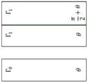
Fig. 1 shows a three-layer linear retarder with the orientation θ and Re ═ Γ0The field of view is compensated by crossed negative A-plates, each having a retardation of Γ1。
Figure 2 shows a prior art reverse order reflection with about 45 symmetry.
Figure 3a shows the functional layer behavior of figure 2 in the transition band.
Fig. 3b shows the functional layer behavior of fig. 2 in the unconverted band.
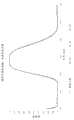
Fig. 4a shows an example of an uncompensated 8-layer green-magenta (GM) retarder stack filter using uniaxial retarders for various angles of incidence in a 45 ° azimuth angle.
Fig. 4b shows an example of an uncompensated 8-layer green-magenta (GM) retarder stack filter using uniaxial retarders for various angles of incidence in the 0 ° azimuth angle.
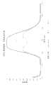
Fig. 5a shows an example of an 8-layer green-magenta (GM) retarder stack filter using uniaxial retarders compensated according to the invention for various angles of incidence in a 45 ° azimuth angle.
Fig. 5b shows an example of an 8-layer green-magenta (GM) retarder stack filter using uniaxial retarders compensated according to the invention for various angles of incidence in the 0 ° azimuth.
Detailed Description
While the embodiments disclosed herein are susceptible to various modifications and alternative forms, specific embodiments thereof have been shown by way of example in the drawings and are herein described in detail. It should be understood, however, that there is no intention to limit the invention to the specific forms disclosed, but on the contrary, the intention is to cover all modifications, equivalents, and alternatives to embodiments of the invention as defined by the appended claims. The present disclosure is described with reference to the drawings, wherein like reference numerals represent substantially similar elements.
The distinction between retarder stack designs that are achromatic in function (i.e., the wavelength range over which the polarization transformation is uniform) and those that otherwise require an achromatic range (which preserves the input SOP) is often subtle. Examples of the former include Pancharatam quarter wave and half wave retarders (S.Pancharatam, "Achromationcombinations of bioreductive plant phase II: an achromationc quater-WP," Proc.Ind.Acad.Sci.41, 137-144 (1955)), the polarization rotators of Koester (C.J.Koester, "Achromationc combinations of half-wave plates," J.Opt.Soc.am.49, 405-409 (1959)), and the pure Achromatic rotator design of Sharp (U.S. Pat. No.8,408,708). The wavelength selective structure can use the delayed dispersion to create an orthogonal polarization spectral region of a specified width. The conventional requirement is for the achromatic regions to appear isotropic (usually along the composite optical axis or intrinsic polarization) and for the regions to convert to orthogonal SOPs. The width of the transition band (i.e., the spectral width between the converted and unconverted bands) separating these regions drives the complexity of the design, as in any Finite Impulse Response (FIR) filter. Such a configuration creates a means of manipulating the colors, for example using a polarization splitter/combiner (Sharp, U.S. patent No.5,751,384), or switching between complementary colors. Since when used non-perpendicularly they are at non-zero RthMay suffer from similar performance degradation problems, and the present invention is therefore applicable to both structural families. Similarly, the compensation scheme can be applied to both transmissive and reflective mode (double pass) structures.
The reference of wide-angle performance is onlyR th0 retarder composition. Monolayer display films having this characteristic include biaxially stretched polycarbonates developed by Nitto Denko and Sumitomo. By stretching in the MD and thickness directions, R inprinciple th0 is possible. However, ReThere is typically an "optimum point" where this state can be accurately maintained during manufacturing, and deviations therefrom at other in-plane retardation values. In addition, z-stretch films are relatively expensive to manufacture and are difficult to purchase today due to the loss of the super-twisted nematic display marketAnd (5) buying.
For generating RthAn alternative prior art solution to 0 is a composite retarder formed by stacking a pair of (crossed) uniaxial films of equal retardation but opposite sign of birefringence. This can be achieved, for example, by coating a negatively birefringent liquid crystal polymer (-a plate) on a stretched positively birefringent substrate (+ a plate). Or may be formed by laminating separately manufactured films, co-extrusion and stretching, or other means. When fabricating a wavelength-dependent polarization manipulation structure, this requires different retardation values for each layer depending on, for example, the particular center wavelength used for conversion/retention. From a practical point of view this presents a business challenge, since such structures are typically very customized rather than large scale applications such as direct view display compensators. Therefore, there is a need for a solution that enables a range of wavelength selective polarization manipulation structures with improved field of view, which only require changing the retardation of (more common) positively birefringent films. Also, with polycarbonate or olefin substrates, + a plates are relatively inexpensive and popular.
Another prior art composite retardation solution separates the function of in-plane retardation from the field of view compensation. For example, a single MD stretched film can produce the desired + A plate ReSingle positive uniaxial retarder with the optical axis perpendicular to the substrate (+ C-plate) makes RthAnd (4) invalidation. The delay of the latter is optimally ReHalf the value. The + C plate may be formed by, for example, stretching a negatively birefringent film in biaxial in-plane (MD/TD), or by vertical alignment of a positively birefringent Liquid Crystal Polymer (LCP) on an isotropic substrate. The C-plate introduces retardation non-perpendicularity only in an azimuth-independent manner. That is, the C-plate always introduces a retardation non-perpendicular with its projection axis following the plane of incidence (POI). In some cases, the additional retardation along the azimuthal angle of 0/90 has no effect when it is hidden by the absorption axis of the adjacent polarizer. However, such a two-layer structure cannot be strictly considered as a compound retarder because there is a different optical axis orientation for each element that is not perpendicular. In the most general sense, compensation requires azimuthal dependence to actually createR th0 linear retarder.
Finally, the use of a-plate material with single sign birefringence can produce aneffective R th0. This is done by achromatic polarization transformation between a pair of matched a plates. In a conventional configuration, the optical axis of the achromatic half wave retarder bisects the equally retarding crossed + a plate, which reflects the SOP. The effect of this polarization reflection is to make ReDoubling the value of RthAnd (4) invalidation. The performance of this approach depends on the strict maintenance of the (composite) optical axis orientation and the retardation of the HW retarder with respect to wavelength.
There is a need for a practical compensation scheme that allows the uniaxial retarder stack to have any degree of customization of the orthogonal incident impulse response, which also preserves the orthogonal incident behavior of the orthogonal incident light. This customization may be accomplished using FIR filter design techniques or any design method that generates the desired impulse response. By linear system theory, the (time domain) impulse response is related to the required wavelength-dependent polarization manipulation.
The solution proposed here is to produce a true composite retarder which establishes pairs ReAnd RthIndependent control of (2). This can be accomplished by forming a three-layer composite retarder comprising a pair of matched-a plates combined with a single + a plate. The + A plate is typically an MD stretch film having application specific in-plane requirements (R)e) The delay of (2). The optical axes of the pair of-A plates intersect such thatR e0, the optical axis is aligned parallel to the + a plate. The latter delay is ideally chosen to achieve R for thecomposite delayer th0. To optimally compensate for R of the + A platethEach element having an in-plane retardation of-Re/2. However, the individual retardation values of the-A plates can be at a larger ReThe improved field of view performance over the range of values results, which makes it a very practical way of universal compensation.
Although R isthTypically associated with a single retarder, but retarder stacks having different ranges of optical axis orientations can be considered to have a composite (or composite) RthValue (R)thC). When additional retarder layers are added, the spectrum required for the synthesis will increase the span of the pulse sequence, as requiredThe spectrum is for example achromatic converted to orthogonal SOP. In a stack with N + a plate retarders, the slowest wave sees only the extraordinary refractive index (index) of each retarder, while the fastest wave sees only the ordinary refractive index (index) of each retarder. Retarders of uniform thickness (each having R)eDelay) stack may be considered to have NReComposite in-plane retardation and NRthThe composite z-delay of (1). How the Z-retardance affects performance non-perpendicularity is design specific, depending on the distribution of optical axis orientation relative to the plane of incidence (POI). In the case of achromatic conversion, it can manifest as, for example, a uniform shift in the orthogonal incident spectrum, and/or a conversion failure, which can manifest as a total loss of optical density of the filter or sidelobes. In any event, in applications requiring a wide acceptance angle, it may cause the stack to fail.
A three-layer composite retarder has the practical advantage of enabling field-of-view compensation over a wide range of orthogonal incident polarization transformations. However, for each layer of the retarder stack design, a three-layer composite retarder is typically involved. The increase of the number of retarders by three times increases the manufacturing cost and the thickness of the product. Since solvent soldering is often used to form the retarder stack, the need to bond different materials may make this approach impractical. One solution is to create a retarder stack that incorporates R in a manner that allows compensation using a small number of layersthCIt is desirable to use a pair of crossed-a plate retarders according to the present invention.
From each having RthA general delayer stack of 0 may have an exemplary performance in preserving impulse response non-verticality. A pair of matched-a plate retarders (each having a retardance Γ) may be used1) Combined application specific retardation value + Γ0Is used to construct a linear retarder with stable linear eigen-polarization and RthA true complex retarder of 0. This configuration is shown in FIG. 1 and is when the compensator retardance has opposite birefringence signs and has a half retardance, or Γ, of the value of the retardance applied specifically1=-Γ0At/2, the arrangement isThere is an optimum non-vertical performance. However, the present invention recognizes the benefits of a "universal compensator" that can be easily manufactured and applied to a range of retardation values with significant field of view benefits. For example, a compensator that over/under compensates for a particular in-plane retardance may deliver (for example) a composite RthCThis still has a huge performance benefit of non-verticality, ± 0.2.
Pairs of retarder stacks with specific symmetry and their behavior are described in the prior art (see chapter 6 of "Polarization Engineering for LCD projection" by Robinson et al.) these include reverse order (related to e.g. reflection mode), reverse order reflection of about zero, reverse order reflection of about 45 ° and reverse order of crossing (identity matrix at normal incidence). the latter is omitted from the analysis as it requires a transformation between stacks to produce a non-trivial transfer function. fig. 2 shows a general configuration of reverse order reflection of about 45 °, where each retarder has a uniform retardation Γ αiRepresenting the optical axis orientation of each positive uniaxial retarder. Fig. 3a shows the simplified structure of fig. 2 for the converted frequency band, while fig. 3b shows the simplified structure for the unconverted frequency band. As described in the reference, these simplifications relate to the relative rotation and complex linear delays.
Fig. 3a shows the behavior of the stack for a partial spectrum converted to an orthogonal SOP, and fig. 3b shows the behavior of the stack for a partial spectrum preserving the input linear SOP (0/90 deg.). In this case, the same thickness stack is assumed. In the conversion portion of the spectrum, there are six composite elements, three of which are independent. There is an input linear compound retarder having a retardation of ΓcAnd has an optical axis along the input polarization. Followed by a 45 deg. rotator, then a second linear compound retarder having a retardation of ΓcAnd has an optical axis along the input polarization. As shown, the symmetrical relationship between the two stacks yields the characteristics of the second set of elements. At normal incidence, the external linear complex retarder is effectively hidden, while the rotator is the only functional element. The central compound retarders are also effectively hidden because their optical axes are crossed (i.e., they are crossed)Perpendicular to each other). In the non-vertical case, the central composite retarder acts as a crossed + a plate, which may limit performance.
For non-perpendicular light rays, the converted band must see a net rotation that remains 90 °, ideally without compound retardation. An outwardly facing retarder (Γ)c) Adjacent to the polarizer/analyzer, a key requirement is therefore that the composite optical axis remain wavelength stable along the extinction axis of the polarizer. Assuming that the rotator acts as a non-vertical design, the structure behaves as if it were with respect to the central compound retarder optical axis Γc' input polarization is introduced along ± 45 °. Assuming the composite axis remains wavelength stable non-perpendicular, the central crossed + a plate has little performance degradation at the ± 45 ° azimuth, while introducing non-perpendicular retardation mainly along the 0/90 ° azimuth. The present invention recognizes that maintaining performance requires introducing an azimuth-dependent compensation. This preferably uses crossed negative A plates along an azimuth angle of 0/90 DEG, the retardation of which is substantially equal to and in combination with the composite retardation Γc' the opposite is true.
An important aspect of obtaining good non-perpendicular performance is that the rotator achieves a stable performance at all times. The preferred stack design focuses the optical axis of one stack around 0, which means that the optical axis of the second stack is focused around 90. When used, have Rth/ReWhen it is a single axis retarder of 1/2, this enables rotation in unison, with R to two index positionsthCAnd (4) merging. R in the form of a central cross + A plate, opposing external retardersthCIs design dependent such that the optimum compensation is also design dependent.
Previous design considerations have had an intuitive self-compensating aspect. If the entrance face is along the input polarizer, the spectrum associated with one stack exhibits substantially a pure blue shift, while the spectrum associated with the other stack exhibits substantially a pure red shift. The opposite is true when the POI is in the orthogonal direction. When used as a filter, the associated average of the behavior of each stack means that the central wavelength of the complex transform, in particular the 50% point, remains substantially constant with respect to the angle of incidence. I.e. associated with a central cross-complex delay is assumedRthIs invalidated. This can be contrasted with an unconstrained retarder stack design, as described in U.S. patent No.5,751,384. Typically, the optical axis is distributed over a wide azimuthal range, and thus there is no uniform retardation shift of the structure. At a particular azimuth angle, one retarder may show the largest red shift, another one does not show the shift, and yet another one shows the largest blue shift. In this case, the required orthogonal incident pulse function is destroyed as the angle of incidence increases.
Summarizing the conversion band of the present example, a "small angle" design preferably provides a stable non-perpendicular rotation, with a compound central retardation with a stable optical axis. Since the optical axis is focused around 0/90 °, there is little performance degradation at the very small ± 45 ° azimuthal angle of the retardation shift of each film. This is also the reason why the compensation of the converted band is very dependent on the azimuth angle. When the stacks are paired according to symmetry, there is a steady 90 ° rotation, with a large proportion (depending on the design) of RthIn the form of crossed + a plates with wavelength-stable optical axes. RthCThe merging of a portion of (a) at the midpoint allows the use of a single crossed-a plate compensator at the midpoint to effectively eliminate RthCIs present. The optimal compensation substantially matches the-a plate compensator to the compensator of the central compound retarder and corrects primarily polarization at an azimuth angle of 0/90 °.
If the purpose of the structure is to selectively manipulate polarization, then precisely preserving the wavelength range of the input SOP may introduce other constraints. Fig. 3b shows the behavior of the stack pair in this case. Also, there is a composite retardance Γ that intersects the equivalent cross retardanceu. For this symmetry, the structure is purely isotropic (R) at normal incidenceeIs zero). In order to keep the output consistent with the angle of incidence, the composite axis only needs to be kept stable along the wavelength of the polarizer. RthThe value does not matter because of the retardation introduced along the optical axis of the compound retarder. Note that the cross-A plate compensation of the present invention has no significant effect on the unconverted band because the optical axis is along the polarizer.
Table 1 shows an example of a small angle retarder stack filter design over a range of N values according to the previously described criteria. The birefringence dispersion of Polycarbonate (PC) is used to generate a specific filter spectrum using a compensator with zero birefringence dispersion. The 50% transition point of the design is consistent throughout the design, with the transition slope increasing with the addition of the additive layer.

Table 1 for a specific example of a retarder stack filter, the angle of each layer of the stack is input. This has a pass/block band ripple of 0.5% for a particular duty cycle. The second stack conforms to a reverse order reflection of about 45 deg. symmetry.
Note that the compensation values for the-a plate in table 1 do not increase consistently with increasing number of layers.
Example 1: 14-layer filter using reverse order reflection compensation of about 45 deg
Using computer models to illustrate the relationship to ΓcAnd Γc' related RthCRelative ratio of (a). A 14-layer green-magenta filter using the design of table 1 was used, where each layer had a 1.5-wave retardation at 530 nm. Thus, for each stack, ReCThe value of (b) is 5565nm at 530 nm. The best performance at 0/90 ° azimuth at 25 ° incident angle was obtained using cross-a plates, each with a 2100nm retardation. This should be in accordance with Γc' somewhat close match, indicating ΓcAbout 3465 nm. Each stack is then swapped end-to-end. Although the central retardance should now be ΓcBut the rotation (inverse) is substantially preserved. After repeated optimization, the compensator value was selected to be 4200 nm. Adding the two optimized compensation values indicates the total ReCAbout 6300nm, which is quite close to the above calculation based on film retardation. Determining if it is possible to merge R along the input polarizationthCThe design of (3) does not need compensation.
Example 2: 8-layer filter using reverse order reflection compensation of about 45 deg
FIGS. 4 and 5 show the setup of Table 1Between crossed perfect polarizers, there are 8 layers at each angle of incidence (0-25 °). Each layer has a 1.5-wave retardance at 540nm, giving a composite retardance of 3240nm for each stack. Figure 4a shows an uncompensated design along a 45 azimuth angle where both the pass band and stop band performance are relatively stable. This indicates the non-perpendicular stability of the rotation and compound axes, and the absence of Γ in this azimuthal anglecThe effect of (1). Fig. 4b shows an uncompensated design with an azimuth angle of 0/90 °. Note that the composite optical axis remains wavelength stable and therefore the unconverted band does not change much, so there is little leakage in the blue/red portion of the spectrum. As the green performance decreases with angle of incidence, it takes the form of a peak transmission loss. There is no apparent overall red/blue shift due to the self-compensation of the two stacks at substantially cancelled pure delay offsets. Fig. 5a shows the performance at ± 45 ° for the incoming crossed a-plate retarders, with the optimum retardance of 1900nm for each retarder. This can be compared to the spectrum of figure 4a, which shows that compensation does not cause any loss in performance. Fig. 5b shows the performance of the compensation at an azimuth angle of 0/90 deg., indicating that the compensation almost restores the orthogonal incident transmission spectrum. At extreme angles of incidence, the profile is somewhat smooth, but the center wavelength and 50% of the points have little change.
A negatively birefringent uniaxial material is used to create crossed-a plate compensators. Suitable materials include inorganic crystals (e.g., sapphire and lithium niobate), liquid crystal polymers (e.g., a disc/lyotropic liquid crystal material coated on an isotropic substrate) or stretched polymer films (e.g., polystyrene). Materials such as sapphire are particularly attractive because the compensator delay required can be large. The birefringence of sapphire is-0.0081, so that the retardance of a 400 micron thick wafer is about 3200 nm. The wafers may be bonded using adhesives, chemical bonds, or optical contact to form crossed-a plates.
While embodiments of the invention have been illustrated and described in detail in the drawings and foregoing description, such illustration and description are to be considered as exemplary and not restrictive. For example, certain embodiments described above may be combined with other described embodiments and/or arranged in other ways (e.g., the processing elements may be executed in other orders). Accordingly, it should be understood that only the exemplary embodiments and variations thereof have been shown and described.
Claims (18)
1. A composite retarder comprising:
a first planar retarder having two dimensions parallel to a plane and a third or thickness dimension perpendicular to the plane, wherein an optical axis orientation of the first retarder determines an in-plane retardation, and wherein the first retarder has a first retardation in the thickness dimension;
a second planar retarder having two dimensions parallel to a plane and a third or thickness dimension perpendicular to the plane, wherein an optical axis orientation of the second retarder is oriented parallel to an optical axis of the first retarder, and wherein the second retarder has a second retardation in the thickness dimension; and
a third planar retarder having two dimensions parallel to a plane and a third or thickness dimension perpendicular to the plane, wherein an optical axis orientation of the third retarder is crossed relative to an optical axis orientation of the first retarder, and wherein the third retarder has a third retardation in the thickness dimension;
wherein the first delay is opposite in sign to the second delay and the third delay.
2. The composite retarder of claim 1, wherein the second retarder and the third retarder have the same in-plane retardation.
3. The composite retarder of claim 1, wherein the in-plane retardance of the second and third retarders is half the in-plane retardance of the first retarder.
4. The composite retarder of claim 1, wherein the in-plane retardance of the second and third retarders is between 20% and 80% of the in-plane retardance of the first retarder.
5. A retarder stack comprising two or more composite retarders according to claim 1.
6. A composite retarder comprising:
a first a-plate retarder having a first optical axis orientation and a first retardation;
a second a-plate retarder having a second optical axis orientation and a second retardation; and
a third A-plate retarder having a third optical axis orientation and a third retardation, wherein the third optical axis orientation is perpendicular to the second optical axis orientation;
wherein one of the second and third optical axis orientations is perpendicular to the first optical axis orientation;
wherein the first delay is opposite in sign to the second delay and the third delay.
7. The composite retarder of claim 6, wherein the second retarder and the third retarder have the same in-plane retardation.
8. The composite retarder of claim 6, wherein the in-plane retardance of the second and third retarders is half the in-plane retardance of the first retarder.
9. The composite retarder of claim 6, wherein the in-plane retardance of the second and third retarders is between 20% and 80% of the in-plane retardance of the first retarder.
10. A retarder stack comprising two or more composite retarders according to claim 6.
11. A retarder stack for wavelength-dependent manipulation of the polarization state of a light beam passing therethrough, the retarder stack comprising:
a first retarder stack comprising two linear retardation layers, wherein the first retarder stack has a thickness dimension in a direction through which the light passes, and wherein the first retarder stack has a non-zero retardation in the thickness dimension;
a second retarder stack comprising two linear retardation layers, wherein the second retarder stack has a thickness dimension in a direction through which the light passes, and wherein the second retarder stack has a non-zero retardation in the thickness dimension; and
a pair of crossed A-plate retarders positioned between the first retarder stack and the second retarder stack, wherein the pair of crossed A-plate retarders have substantially matched in-plane retardance.
12. The retarder stack of claim 11, wherein the birefringence of the first and second retarder stacks has the same and opposite sign as the birefringence of the crossed a-plate retarder.
13. The retarder stack of claim 11, wherein the retarder stack has a compound in-plane retardation, and wherein the crossed a-plate retarder reduces the incident angle dependence of the compound in-plane retardation.
14. The retarder stack of claim 11, wherein the retarder stack is arranged in a reverse order reflective configuration of approximately 45 degrees, wherein the retarder stack is configured to convert an input polarization state of a predetermined wavelength range to a polarization state orthogonal to the input polarization state, and wherein the pair of crossed a-plate retarders provide azimuth-dependent compensation that reduces the incident angle-dependent variation of the composite in-plane retardation.
15. The retarder stack of claim 14, wherein the retarder stack consists of positive a-plates and the crossed a-plate retarder consists of negative a-plates.
16. The retarder stack of claim 11, wherein the retarder stack does not switch input polarization states over a predetermined wavelength range, and wherein the crossed a-plate retarders do not adversely affect the incident angle dependent variation of the composite in-plane retardation.
17. The retarder stack of claim 13, wherein the azimuth-dependent compensation substantially matches a composite retardance existing between the retarder stacks in retardance and orientation, thereby minimizing the composite in-plane retardance.
18. The retarder stack of claim 14, wherein the combination of the retarder stack and the crossed a-plates produces an orthogonal-incidence composite polarization transformation that is substantially insensitive to incident angle.
Applications Claiming Priority (3)
| Application Number | Priority Date | Filing Date | Title |
|---|---|---|---|
| US201762533547P | 2017-07-17 | 2017-07-17 | |
| US62/533,547 | 2017-07-17 | ||
| PCT/US2018/042523WO2019018419A1 (en) | 2017-07-17 | 2018-07-17 | WIDE-ANGLE COMPENSATION OF UNIAXIAL RETARDANT STACKS |
Publications (1)
| Publication Number | Publication Date |
|---|---|
| CN111108428Atrue CN111108428A (en) | 2020-05-05 |
Family
ID=65000228
Family Applications (1)
| Application Number | Title | Priority Date | Filing Date |
|---|---|---|---|
| CN201880059934.9APendingCN111108428A (en) | 2017-07-17 | 2018-07-17 | Wide angle compensation of uniaxial retarder stacks |
Country Status (6)
| Country | Link |
|---|---|
| US (2) | US11294113B2 (en) |
| EP (1) | EP3642666A4 (en) |
| JP (1) | JP2020528159A (en) |
| CN (1) | CN111108428A (en) |
| AU (1) | AU2018304186A1 (en) |
| WO (1) | WO2019018419A1 (en) |
Families Citing this family (9)
| Publication number | Priority date | Publication date | Assignee | Title |
|---|---|---|---|---|
| JP7263643B2 (en) | 2017-03-08 | 2023-04-25 | メタ プラットフォームズ テクノロジーズ, リミテッド ライアビリティ カンパニー | Wide angle variable neutral density filter |
| CN111108428A (en)* | 2017-07-17 | 2020-05-05 | 加里夏普创新有限责任公司 | Wide angle compensation of uniaxial retarder stacks |
| US11249355B2 (en)* | 2018-01-29 | 2022-02-15 | Gary Sharp Innovations, Llc | Color switch for reduced color cross-talk |
| EP3746822A4 (en) | 2018-01-29 | 2022-01-12 | Gary Sharp Innovations, LLC | Hollow triple-pass optical elements |
| US11320665B2 (en) | 2018-03-02 | 2022-05-03 | Gary Sharp Innovatnons, Llc | Retarder stack pairs for polarization basis vector transformations |
| WO2021173665A1 (en)* | 2020-02-24 | 2021-09-02 | Gary Sharp Innovations, Llc | Digitally reconfigurable neutral density filter |
| WO2024204164A1 (en)* | 2023-03-30 | 2024-10-03 | 富士フイルム株式会社 | Wavelength-selective retardation plate and optical element |
| US12248204B1 (en)* | 2023-05-01 | 2025-03-11 | Meta Platform Technologies, LLC | Broadband polarization rotator and optical switch |
| KR20250016544A (en) | 2023-07-19 | 2025-02-04 | 삼성디스플레이 주식회사 | Display device |
Citations (9)
| Publication number | Priority date | Publication date | Assignee | Title |
|---|---|---|---|---|
| US2607272A (en)* | 1949-02-11 | 1952-08-19 | Bell Telephone Labor Inc | Composite wave plate for light |
| US5751384A (en)* | 1995-05-23 | 1998-05-12 | The Board Of Regents Of The University Of Colorado | Color polarizers for polarizing an additive color spectrum along a first axis and it's compliment along a second axis |
| US6273571B1 (en)* | 1995-05-23 | 2001-08-14 | Colorlink, Inc. | Display architectures using an electronically controlled optical retarder stack |
| CN1860404A (en)* | 2004-11-12 | 2006-11-08 | Lg化学株式会社 | Vertically aligned liquid crystal display |
| US20070076291A1 (en)* | 2005-10-04 | 2007-04-05 | The Boeing Company | Wave plate and associated method |
| US20070279553A1 (en)* | 2005-03-24 | 2007-12-06 | Nitto Denko Corporation | Liquid Crystal Panel, Liquid Crystal Television, and Liquid Crystal Display Apparatus |
| JP2008177581A (en)* | 2007-01-22 | 2008-07-31 | Carl Zeiss Smt Ag | Microlithography projection exposure apparatus |
| US20140313498A1 (en)* | 2012-01-12 | 2014-10-23 | Carl Zeiss Smt Gmbh | Polarization-influencing optical arrangement, in particular in a microlithographic projection exposure apparatus |
| US20140361152A1 (en)* | 2013-06-06 | 2014-12-11 | Kla-Tencor Corporation | System, Method and Apparatus For Polarization Control |
Family Cites Families (168)
| Publication number | Priority date | Publication date | Assignee | Title |
|---|---|---|---|---|
| US4511225A (en) | 1982-12-23 | 1985-04-16 | Lipson Herbert G | Variable neutral density laser goggles |
| US4884876A (en) | 1983-10-30 | 1989-12-05 | Stereographics Corporation | Achromatic liquid crystal shutter for stereoscopic and other applications |
| US5381253A (en) | 1991-11-14 | 1995-01-10 | Board Of Regents Of University Of Colorado | Chiral smectic liquid crystal optical modulators having variable retardation |
| US5528393A (en) | 1989-10-30 | 1996-06-18 | Regents Of The University Of Colorado | Split-element liquid crystal tunable optical filter |
| US5132826A (en) | 1989-10-30 | 1992-07-21 | The University Of Colorado Foundation, Inc. | Ferroelectric liquid crystal tunable filters and color generation |
| US5243455A (en) | 1990-05-11 | 1993-09-07 | The University Of Colorado Foundation, Inc. | Chiral smectic liquid crystal polarization interference filters |
| US5231521A (en) | 1989-10-30 | 1993-07-27 | The University Of Colorado Foundation, Inc. | Chiral smectic liquid crystal polarization interference filters |
| US5493426A (en) | 1991-11-14 | 1996-02-20 | University Of Colorado Foundation, Inc. | Lateral electrode smectic liquid crystal devices |
| US5552912A (en) | 1991-11-14 | 1996-09-03 | Board Of Regents Of The University Of Colorado | Chiral smectic liquid crystal optical modulators |
| US5387958A (en) | 1992-06-30 | 1995-02-07 | Sony Electronics, Inc. | Electro-optical control of light attenuation in the optical path of a camera |
| US5619355A (en) | 1993-10-05 | 1997-04-08 | The Regents Of The University Of Colorado | Liquid crystal handedness switch and color filter |
| US5627666A (en) | 1994-07-27 | 1997-05-06 | Board Of Regents Of The University Of Colorado | Liquid crystal phase modulator using cholesteric circular polarizers |
| US5574553A (en) | 1994-12-27 | 1996-11-12 | The United States Of America As Represented By The Secretary Of The Air Force | Ladar receiver incorporating an optical amplifier and polarization optical mixer |
| US5689317A (en) | 1995-03-22 | 1997-11-18 | Cambridge Research Instrumentation, Inc. | Tunable color filter |
| US6078374A (en) | 1995-04-07 | 2000-06-20 | Colorlink, Inc. | Spatially switched achromatic compound retarder |
| US5658490A (en) | 1995-04-07 | 1997-08-19 | Board Of Regents Of The University Of Colorado | Liquid crystal achromatic compound retarder |
| US6252638B1 (en) | 1995-05-23 | 2001-06-26 | Colorlink, Inc. | Color controllable illumination device, indicator lights, transmissive windows and color filters employing retarder stacks |
| US6704065B1 (en) | 1995-04-07 | 2004-03-09 | Colorlink, Inc. | Optical system for producing a modulated color image |
| US6380997B1 (en) | 1995-04-07 | 2002-04-30 | Colorlink, Inc. | Achromatic polarization inverters for displaying inverse frames in DC balanced liquid crystal displays |
| US6707516B1 (en) | 1995-05-23 | 2004-03-16 | Colorlink, Inc. | Single-panel field-sequential color display systems |
| US5999240A (en)* | 1995-05-23 | 1999-12-07 | Colorlink, Inc. | Optical retarder stack pair for transforming input light into polarization states having saturated color spectra |
| US5822021A (en) | 1996-05-14 | 1998-10-13 | Colorlink, Inc. | Color shutter liquid crystal display system |
| US6882384B1 (en) | 1995-05-23 | 2005-04-19 | Colorlink, Inc. | Color filters and sequencers using color selective light modulators |
| US6183091B1 (en) | 1995-04-07 | 2001-02-06 | Colorlink, Inc. | Color imaging systems and methods |
| US6049367A (en) | 1995-05-23 | 2000-04-11 | Colorlink, Inc. | Polarization manipulating device modulator with retarder stack which preconditions light for modulation and isotropic states |
| US5929946A (en) | 1995-05-23 | 1999-07-27 | Colorlink, Inc. | Retarder stack for preconditioning light for a modulator having modulation and isotropic states of polarization |
| US6417892B1 (en) | 1995-05-23 | 2002-07-09 | Colorlink, Inc. | Color filters, sequencers and displays using color selective light modulators |
| US6141071A (en) | 1995-10-30 | 2000-10-31 | Colorlink, Inc. | Switchable achromatic polarization rotator |
| US5870159A (en) | 1995-10-30 | 1999-02-09 | Kaj | Switchable achromatic polarization rotator |
| US5781268A (en) | 1996-04-09 | 1998-07-14 | Board Of Regents Of The University Of Colorado | Polarization-insensitive fabry-perot tunable filter |
| US5715023A (en) | 1996-04-30 | 1998-02-03 | Kaiser Electro-Optics, Inc. | Plane parallel optical collimating device employing a cholesteric liquid crystal |
| US6028656A (en) | 1996-10-09 | 2000-02-22 | Cambridge Research & Instrumentation Inc. | Optical polarization switch and method of using same |
| US5892559A (en) | 1996-11-25 | 1999-04-06 | Colorlink, Inc. | Chromaticity compensating liquid crystal filter |
| US5892612A (en) | 1997-08-07 | 1999-04-06 | Cambridge Research & Instrumentation Inc. | Tunable optical filter with white state |
| GB2331812A (en) | 1997-11-26 | 1999-06-02 | Sharp Kk | Optical retardation devices |
| US6075651A (en) | 1999-01-28 | 2000-06-13 | Kaiser Electro-Optics, Inc. | Compact collimating apparatus |
| US6903789B1 (en)* | 1999-09-16 | 2005-06-07 | Merck Patent Gmbh | Optical compensator and liquid crystal display II |
| US6638583B1 (en) | 2000-03-16 | 2003-10-28 | Colorlink, Inc. | Method and apparatus for laminating stacks of polycarbonate films |
| US6650377B2 (en) | 2000-05-08 | 2003-11-18 | Colorlink, Inc. | Two panel projection systems |
| US7002752B2 (en) | 2001-11-30 | 2006-02-21 | Colorlink, Inc. | Three-panel color management systems and methods |
| US6816309B2 (en) | 2001-11-30 | 2004-11-09 | Colorlink, Inc. | Compensated color management systems and methods |
| US6961179B2 (en) | 2001-11-30 | 2005-11-01 | Colorlink, Inc. | Compensated color management systems and methods |
| WO2003054111A1 (en)* | 2001-12-12 | 2003-07-03 | Merck Patent Gmbh | Biaxial film |
| US7083282B1 (en) | 2002-02-19 | 2006-08-01 | Colorlink, Inc. | Light recycling colored light source and method of using |
| US7298386B1 (en) | 2002-05-14 | 2007-11-20 | Colorlink, Inc. | Sequential color display system and method |
| US7154667B2 (en) | 2002-08-30 | 2006-12-26 | Colorlink, Inc. | Birefringent networks |
| US7106509B2 (en) | 2002-09-06 | 2006-09-12 | Colorlink, Inc. | Filter for enhancing vision and/or protecting the eyes and method of making a filter |
| US6922221B2 (en) | 2002-10-17 | 2005-07-26 | Research Foundation Of The University Of Central Florida | Broadband quarter-wave film device including in combination a chromatic half-wave film and a TN-LC polymeric film |
| JP2006505014A (en) | 2002-10-30 | 2006-02-09 | カラーリンク・インコーポレイテッド | Multiple obliquely oriented plate compensators for multiple projection display systems |
| US7195356B1 (en) | 2003-09-22 | 2007-03-27 | Colorlink, Inc. | Split-path color switching system and method |
| US20090052838A1 (en) | 2004-03-22 | 2009-02-26 | Mcdowall Ian | Electrically controlled optical elements and method |
| US7345723B2 (en)* | 2004-05-24 | 2008-03-18 | Colorlink, Inc. | LC panel compensators |
| EP1759238A4 (en) | 2004-05-24 | 2009-07-22 | Colorlink Inc | High durability and high performance polarization optics using a low-elasticity organic layer |
| US7320521B2 (en)* | 2004-07-12 | 2008-01-22 | Next Wave Optics, Inc. | Optical engine architectures |
| US7527834B2 (en)* | 2004-08-31 | 2009-05-05 | Nitto Denko Corporation | Retardation films for the elimination of leakage of light through cross polarizers in LCD |
| JP2008524773A (en) | 2004-12-16 | 2008-07-10 | カラーリンク・インコーポレイテッド | Composite quarter wave plate for optical disk pickup head |
| CN1954244B (en)* | 2005-02-25 | 2010-07-21 | 日东电工株式会社 | Polarizing element, liquid crystal panel, liquid crystal television and liquid crystal display device |
| US20060290853A1 (en) | 2005-06-27 | 2006-12-28 | Qi Hong | Wide-acceptance-angle circular polarizers |
| US7692746B2 (en) | 2005-08-01 | 2010-04-06 | Real D | Digitally-switchable bandpass filter |
| WO2007027821A2 (en) | 2005-08-30 | 2007-03-08 | Colorlink, Inc. | High yield bonding process for manufacturing polycarbonate polarized lenses |
| US7528906B2 (en) | 2006-01-23 | 2009-05-05 | Real D | Achromatic polarization switches |
| JP5508721B2 (en) | 2006-02-10 | 2014-06-04 | リアルディー インコーポレイテッド | Multifunctional active matrix liquid crystal display |
| WO2008001582A1 (en)* | 2006-06-28 | 2008-01-03 | Sharp Kabushiki Kaisha | Complex birefringent medium, polarizing plate, and liquid crystal device |
| JP4943790B2 (en)* | 2006-09-15 | 2012-05-30 | 株式会社リコー | Polarization conversion unit and image projection apparatus |
| JP5635773B2 (en) | 2006-09-29 | 2014-12-03 | リアルディー インコーポレイテッドRealD Inc. | Polarization conversion system for stereoscopic projection, projection system, and stereoscopic image projection method |
| JP4998941B2 (en)* | 2006-11-20 | 2012-08-15 | 日東電工株式会社 | Laminated optical film, liquid crystal panel and liquid crystal display device using laminated optical film |
| JP4761395B2 (en)* | 2006-11-24 | 2011-08-31 | 日東電工株式会社 | Laminated optical film, liquid crystal panel and liquid crystal display device using laminated optical film |
| WO2008067558A2 (en) | 2006-11-30 | 2008-06-05 | Real D | High performance shutter glasses for multifunctional display |
| US8427394B2 (en) | 2006-11-30 | 2013-04-23 | Reald Inc. | Shutter glass drive scheme for sequential-color displays |
| US8727536B2 (en) | 2007-05-09 | 2014-05-20 | Reald Inc. | Polarization conversion system and method for projecting polarization encoded imagery |
| US20080309854A1 (en)* | 2007-06-15 | 2008-12-18 | Zhibing Ge | Wide Viewing Angle and Broadband Circular Polarizers for Transflective Liquid Crystal Displays |
| US7583439B2 (en) | 2007-08-09 | 2009-09-01 | University Of Central Florida Research Foundation, Inc. | Wide-angle and broadband polarization converter |
| WO2009049265A1 (en) | 2007-10-11 | 2009-04-16 | Real D | Curved optical filters |
| KR101939935B1 (en) | 2008-01-28 | 2019-01-17 | 리얼디 인크. | Polarization preserving front projection screen |
| EP2361401B1 (en) | 2008-12-01 | 2017-09-06 | RealD Inc. | Stereoscopic projection systems and methods for employing spatial multiplexing at an intermediate image plane |
| KR101323072B1 (en)* | 2009-05-04 | 2013-10-29 | 엘지디스플레이 주식회사 | Polarizing plate assembly having patterned retard and fabricating method thereof and image display device using it |
| KR20120018368A (en) | 2009-05-22 | 2012-03-02 | 리얼디 인크. | Polarization modulation wheel |
| KR20120050982A (en) | 2009-06-29 | 2012-05-21 | 리얼디 인크. | Stereoscopic projection system employing spatial multiplexing at an intermediate image plane |
| US8194315B2 (en) | 2009-12-22 | 2012-06-05 | ReaID Inc. | Polarization preserving projection screen with engineered particle and method for making same |
| EP2517071B1 (en) | 2009-12-22 | 2019-05-22 | RealD Inc. | Polarization preserving projection screen with engineered pigment and method for making same |
| US8169699B2 (en) | 2009-12-22 | 2012-05-01 | Reald Inc. | Polarization preserving projection screen with engineered pigment and method for making same |
| CN102804058B (en) | 2010-01-20 | 2016-04-20 | 瑞尔D股份有限公司 | Wide field-of-view stereoscopic projection system |
| US8328362B2 (en) | 2010-02-24 | 2012-12-11 | Reald Inc. | Waveplate compensation in projection polarization conversion system |
| CN103080813A (en) | 2010-06-08 | 2013-05-01 | 瑞尔D股份有限公司 | Stereoscopic liquid crystal display systems |
| EP2593829B1 (en) | 2010-07-13 | 2021-09-22 | RealD Inc. | Field-of-view compensated polarization switch for short-throw 3d projection |
| US8820937B2 (en) | 2010-08-17 | 2014-09-02 | Lc-Tec Displays Ab | Optical polarization state modulator assembly for use in stereoscopic three-dimensional image projection system |
| US8184215B2 (en) | 2010-08-17 | 2012-05-22 | Lc-Tec Displays Ab | High-speed liquid crystal polarization modulator |
| US8908081B2 (en) | 2010-09-09 | 2014-12-09 | Red.Com, Inc. | Optical filter opacity control for reducing temporal aliasing in motion picture capture |
| US8760760B2 (en) | 2010-09-30 | 2014-06-24 | Reald Inc. | Cleanable coating for projection screen |
| US20140041205A1 (en) | 2010-11-19 | 2014-02-13 | Reald Inc. | Method of manufacturing directional backlight apparatus and directional structured optical film |
| CN103492933B (en) | 2011-02-24 | 2015-08-19 | 瑞尔D股份有限公司 | Stereo glasses with stray light management |
| US8526106B2 (en) | 2011-03-09 | 2013-09-03 | Reald Inc. | Method and apparatus for managing optical non-uniformities in seaming processes |
| CN103688211B (en) | 2011-05-12 | 2017-02-15 | 瑞尔D股份有限公司 | Polarization compensated stereoscopic systems |
| US8941801B2 (en) | 2011-06-14 | 2015-01-27 | Reald Inc. | In-plane switched active retarder for stereoscopic display systems |
| US8724218B2 (en) | 2011-07-07 | 2014-05-13 | Reald Inc. | Speckle reduction using screen vibration techniques and apparatus |
| CN103782233B (en) | 2011-07-13 | 2016-10-26 | 瑞尔D股份有限公司 | For obtaining the method and apparatus engaging screen material of minimum optical change |
| US8780433B2 (en)* | 2011-09-28 | 2014-07-15 | General Photonics Corporation | Polarization scrambling based on cascaded optical polarization devices having modulated optical retardation |
| CN103959136A (en) | 2011-11-30 | 2014-07-30 | 瑞尔D股份有限公司 | Laser beam scanned display apparatus and method thereof |
| WO2013109979A1 (en) | 2012-01-19 | 2013-07-25 | Lc-Tec Displays Ab | Rapid switching optical shutter alternately transmitting visible radiation and near infrared radiation |
| US9229139B2 (en) | 2012-01-19 | 2016-01-05 | Lc-Tec Displays Ab | Enhanced vision system implemented with optical shutter alternately transmitting visible radiation and near infrared radiation |
| WO2013134294A1 (en) | 2012-03-06 | 2013-09-12 | Reald Inc. | Light efficient acoustically transmissive front projection screens |
| WO2013169987A1 (en) | 2012-05-10 | 2013-11-14 | Oakley, Inc. | Eyewear with laminated functional layers |
| US9235057B2 (en) | 2012-05-18 | 2016-01-12 | Reald Inc. | Polarization recovery in a directional display device |
| US9350980B2 (en) | 2012-05-18 | 2016-05-24 | Reald Inc. | Crosstalk suppression in a directional backlight |
| EP2893396A4 (en) | 2012-09-06 | 2016-04-27 | Reald Inc | High elastic modulus projection screen substrates |
| EP2941667B1 (en) | 2013-01-04 | 2019-11-06 | RealD Inc. | Multi-primary backlight for multi-functional active-matrix liquid crystal displays |
| US8630037B1 (en) | 2013-02-14 | 2014-01-14 | L-C TEC Displays AB | Optical shutter for day-night filter operation |
| US9664945B2 (en) | 2013-03-29 | 2017-05-30 | Au Optronics Corporation | Display apparatus |
| US9380220B2 (en) | 2013-04-05 | 2016-06-28 | Red.Com, Inc. | Optical filtering for cameras |
| US9121999B2 (en) | 2013-07-30 | 2015-09-01 | Au Optronics Corporation | Optical film and display device having the same |
| US10012884B2 (en) | 2013-09-23 | 2018-07-03 | Lc-Tec Displays Ab | High contrast electro-optic liquid crystal camera iris providing angle independent transmission for uniform gray shades |
| US10401700B2 (en) | 2013-09-23 | 2019-09-03 | Lc-Tec Displays Ab | High contrast electro-optic liquid crystal camera iris including liquid crystal material mixed with a dye to improve achromatic performance |
| US8891042B1 (en) | 2013-09-23 | 2014-11-18 | Lc-Tec Displays Ab | Electro-optic liquid crystal camera iris providing angle independent transmission for uniform gray shades |
| WO2015073838A1 (en) | 2013-11-15 | 2015-05-21 | Reald Inc. | High dynamic range, high contrast projection systems |
| US9575335B1 (en) | 2014-01-10 | 2017-02-21 | Oakley, Inc. | Eyewear with chroma enhancement for specific activities |
| AU2015335897B2 (en) | 2014-10-21 | 2021-04-22 | Reald Inc. | High power handling polarization switches |
| US10082675B2 (en) | 2014-10-21 | 2018-09-25 | Reald Inc. | High power handling polarization switches |
| KR102069024B1 (en) | 2015-09-03 | 2020-01-22 | 쓰리엠 이노베이티브 프로퍼티즈 컴파니 | Optical system |
| EP3365711A4 (en)* | 2015-10-23 | 2019-07-10 | Gary D. Sharp | OPTICAL FILTER WITH COLOR ACCENT |
| US9680132B1 (en) | 2015-11-30 | 2017-06-13 | Industrial Technology Research Institute | Display device and optical film |
| US10203566B2 (en) | 2015-12-21 | 2019-02-12 | Facebook Technologies, Llc | Enhanced spatial resolution using a segmented electrode array |
| WO2017172277A1 (en) | 2016-03-28 | 2017-10-05 | Lc-Tec Displays Ab | Electro-optic guest-host liquid crystal variable transmission filter with wide viewing angle |
| US10203489B2 (en) | 2016-08-02 | 2019-02-12 | Apple Inc. | Optical system for head-mounted display |
| US10901205B1 (en) | 2016-08-09 | 2021-01-26 | Facebook Technologies, Llc | Focus adjusting liquid crystal lenses in a head-mounted display |
| US10394040B2 (en) | 2016-10-12 | 2019-08-27 | Facebook Technologies, Llc | Head mounted display including pancake lens block |
| US10416461B2 (en) | 2016-10-27 | 2019-09-17 | Facebook Technologies, Llc | Pancake lens with large FOV |
| US10451947B1 (en) | 2016-10-31 | 2019-10-22 | Facebook Technologies, Llc | Apochromatic pancharatnam berry phase (PBP) liquid crystal structures for head-mounted displays |
| US10248001B1 (en) | 2016-11-16 | 2019-04-02 | Facebook Technologies, Llc | Varifocal structure comprising a liquid lens structure in optical series with a liquid crystal lens in a head-mounted display |
| US10151961B2 (en) | 2016-12-29 | 2018-12-11 | Facebook Technologies, Llc | Switchable bragg gratings for chromatic error correction of pancharatnam berry phase (PBP) components |
| US10866429B2 (en) | 2017-01-24 | 2020-12-15 | Gary Sharp Innovations, Llc | Tunable color enhancement filter |
| US10712485B1 (en) | 2017-02-28 | 2020-07-14 | Facebook Technologies, Llc | Composite optical coating on a curved optical surface |
| JP7263643B2 (en) | 2017-03-08 | 2023-04-25 | メタ プラットフォームズ テクノロジーズ, リミテッド ライアビリティ カンパニー | Wide angle variable neutral density filter |
| US10451885B2 (en) | 2017-03-28 | 2019-10-22 | Facebook Technologies, Llc | Multifocal system using pixel level polarization controllers and folded optics |
| WO2018191593A1 (en) | 2017-04-13 | 2018-10-18 | Sharp Gary D | Chromatic polarization filtering that is input specific |
| CN116841075A (en)* | 2017-05-08 | 2023-10-03 | 瑞尔D斯帕克有限责任公司 | Optical stack for directional display |
| US10678057B2 (en) | 2017-05-17 | 2020-06-09 | Facebook Technologies, Llc | Liquid crystal cells for polarization rotation |
| CN111108428A (en) | 2017-07-17 | 2020-05-05 | 加里夏普创新有限责任公司 | Wide angle compensation of uniaxial retarder stacks |
| US10691198B1 (en) | 2017-09-21 | 2020-06-23 | Facebook Technologies, Llc | Attenuation of Narcissus effect in pancake lens assembly |
| US10474229B1 (en) | 2017-11-01 | 2019-11-12 | Facebook Technologies, Llc | Folded viewing optics with high eye tracking contrast ratio |
| US10678116B1 (en) | 2017-11-09 | 2020-06-09 | Facebook Technologies, Llc | Active multi-color PBP elements |
| US10739651B2 (en) | 2017-11-17 | 2020-08-11 | Gary Sharp Innovations, Llc | Self-compensating liquid crystal retardation switch |
| US10845597B1 (en) | 2017-11-27 | 2020-11-24 | Facebook Technologies, Llc | Pancake lenses using Fresnel surfaces |
| US10520772B1 (en) | 2017-12-15 | 2019-12-31 | Facebook Technologies, Llc | Self-compensated liquid crystal polymer coatings on curved optical surface |
| US10598928B1 (en) | 2017-12-21 | 2020-03-24 | Facebook Technologies, Llc | Light redirection structures for eye tracking systems |
| EP3746822A4 (en) | 2018-01-29 | 2022-01-12 | Gary Sharp Innovations, LLC | Hollow triple-pass optical elements |
| US11249355B2 (en) | 2018-01-29 | 2022-02-15 | Gary Sharp Innovations, Llc | Color switch for reduced color cross-talk |
| US10934381B2 (en) | 2018-02-20 | 2021-03-02 | Board Of Supervisors Of Louisiana State University And Agricultural And Mechanical College | Composition and method of making two-way shape memory polymer based sealant |
| US11320665B2 (en) | 2018-03-02 | 2022-05-03 | Gary Sharp Innovatnons, Llc | Retarder stack pairs for polarization basis vector transformations |
| US11048075B1 (en) | 2018-03-29 | 2021-06-29 | Facebook Technologies, Llc | Optical lens assemblies and related methods |
| US10609364B2 (en) | 2018-04-06 | 2020-03-31 | Facebook Technologies, Llc | Pupil swim corrected lens for head mounted display |
| US10902820B2 (en) | 2018-04-16 | 2021-01-26 | Facebook Technologies, Llc | Display device with dynamic resolution enhancement |
| US10871653B1 (en) | 2018-04-24 | 2020-12-22 | Lc-Tec Displays Ab | Viewing direction independent single-layer, pixelated light dimming filter |
| US10670861B2 (en) | 2018-06-04 | 2020-06-02 | Facebook Technologies, Llc | Optical assembly with waveplate configuration for ghost image reduction |
| US11226483B2 (en) | 2018-06-07 | 2022-01-18 | Facebook Technologies, Llc | Reverse-order crossed pancake lens with a shaped polarizer |
| US10914953B1 (en) | 2018-06-11 | 2021-02-09 | Facebook Technologies, Llc | Varifocal waveguide display using tunable lens |
| US10495798B1 (en) | 2018-08-07 | 2019-12-03 | Facebook Technologies, Llc | Switchable reflective circular polarizer in head-mounted display |
| US10642048B2 (en) | 2018-08-07 | 2020-05-05 | Facebook Technologies, Llc | Reflective circular polarizer for head-mounted display |
| US10545348B1 (en) | 2018-08-16 | 2020-01-28 | Facebook Technologies, Llc | Transmission improvement for flat lens based AR/VR glasses |
| US11740481B2 (en) | 2018-10-02 | 2023-08-29 | Meta Platforms Technologies, Llc | Polarization folded path device with complementary angle filtering |
| US10839609B2 (en) | 2018-10-05 | 2020-11-17 | Facebook Technologies, Llc | Apparatus, systems, and methods for display devices including local dimming |
| CN113167951A (en) | 2018-10-12 | 2021-07-23 | 加里夏普创新有限责任公司 | Polarization based optical filter with angle sensitive transmission |
| CN116088082A (en) | 2018-11-02 | 2023-05-09 | 元平台技术有限公司 | Compact polarization-based multipass optical architecture |
| US10600352B1 (en) | 2018-12-04 | 2020-03-24 | Facebook Technologies, Llc | Display device with a switchable window and see-through pancake lens assembly |
| US10838214B2 (en) | 2018-12-14 | 2020-11-17 | Facebook Technologies, Llc | Angle compensating lens and display |
| US10935790B2 (en) | 2019-02-07 | 2021-03-02 | Facebook Technologies, Llc | Active flexible liquid crystal optical devices |
| JP2022526184A (en) | 2019-04-11 | 2022-05-23 | ゲイリー シャープ イノベーションズ リミテッド ライアビリティ カンパニー | Polarization compensator for inclined surfaces |
| KR20220031680A (en) | 2019-07-08 | 2022-03-11 | 게리 샤프 이노베이션즈 엘엘씨 | High-contrast, compact polarization-based collimator |
| US10890823B1 (en) | 2019-10-18 | 2021-01-12 | Facebook Technologies, Llc | Pitch variable optical devices and systems containing the same |
- 2018
- 2018-07-17CNCN201880059934.9Apatent/CN111108428A/enactivePending
- 2018-07-17EPEP18835931.9Apatent/EP3642666A4/ennot_activeWithdrawn
- 2018-07-17USUS16/037,934patent/US11294113B2/enactiveActive
- 2018-07-17AUAU2018304186Apatent/AU2018304186A1/ennot_activeAbandoned
- 2018-07-17WOPCT/US2018/042523patent/WO2019018419A1/ennot_activeCeased
- 2018-07-17JPJP2020502237Apatent/JP2020528159A/enactivePending
- 2022
- 2022-03-12USUS17/693,342patent/US11703623B2/enactiveActive
Patent Citations (9)
| Publication number | Priority date | Publication date | Assignee | Title |
|---|---|---|---|---|
| US2607272A (en)* | 1949-02-11 | 1952-08-19 | Bell Telephone Labor Inc | Composite wave plate for light |
| US5751384A (en)* | 1995-05-23 | 1998-05-12 | The Board Of Regents Of The University Of Colorado | Color polarizers for polarizing an additive color spectrum along a first axis and it's compliment along a second axis |
| US6273571B1 (en)* | 1995-05-23 | 2001-08-14 | Colorlink, Inc. | Display architectures using an electronically controlled optical retarder stack |
| CN1860404A (en)* | 2004-11-12 | 2006-11-08 | Lg化学株式会社 | Vertically aligned liquid crystal display |
| US20070279553A1 (en)* | 2005-03-24 | 2007-12-06 | Nitto Denko Corporation | Liquid Crystal Panel, Liquid Crystal Television, and Liquid Crystal Display Apparatus |
| US20070076291A1 (en)* | 2005-10-04 | 2007-04-05 | The Boeing Company | Wave plate and associated method |
| JP2008177581A (en)* | 2007-01-22 | 2008-07-31 | Carl Zeiss Smt Ag | Microlithography projection exposure apparatus |
| US20140313498A1 (en)* | 2012-01-12 | 2014-10-23 | Carl Zeiss Smt Gmbh | Polarization-influencing optical arrangement, in particular in a microlithographic projection exposure apparatus |
| US20140361152A1 (en)* | 2013-06-06 | 2014-12-11 | Kla-Tencor Corporation | System, Method and Apparatus For Polarization Control |
Also Published As
| Publication number | Publication date |
|---|---|
| EP3642666A1 (en) | 2020-04-29 |
| US20220196899A1 (en) | 2022-06-23 |
| US11294113B2 (en) | 2022-04-05 |
| JP2020528159A (en) | 2020-09-17 |
| US20190018177A1 (en) | 2019-01-17 |
| EP3642666A4 (en) | 2021-04-14 |
| WO2019018419A1 (en) | 2019-01-24 |
| AU2018304186A1 (en) | 2020-02-06 |
| US11703623B2 (en) | 2023-07-18 |
Similar Documents
| Publication | Publication Date | Title |
|---|---|---|
| CN111108428A (en) | Wide angle compensation of uniaxial retarder stacks | |
| US6816309B2 (en) | Compensated color management systems and methods | |
| JP4884380B2 (en) | LC panel compensator | |
| CN100440009C (en) | Finely tuned phase retarders with negative birefringence | |
| KR101498137B1 (en) | Single-layer birefringent crystal trim retarders | |
| CN112219143B (en) | Retarder stack pair for polarization basis vector conversion | |
| US20040165126A1 (en) | Multi-layer diffraction type polarizer and liquid crystal element | |
| JPH1090521A (en) | Polarization axis rotating laminated phase difference plate and projection type liquid crystal display device using the same | |
| US5867239A (en) | Wide angle optical retarder | |
| US6040942A (en) | Polarization separator/combiner | |
| CN110967863A (en) | Liquid crystal display device | |
| JP2003035820A (en) | Circularly polarizing plate and liquid crystal display using the same | |
| US7969543B2 (en) | Retardation films having single retardation value with variation | |
| US20040042077A1 (en) | Birefringent networks | |
| KR20030020358A (en) | Achromatic apparatus for producing a wavelength-independent high contrast light signal | |
| JPH10239518A (en) | Phase difference plate, and polarizing element using it | |
| Baur | A new type of beam-splitting polarizer cube | |
| WO2024190775A1 (en) | Polarization interference element and filter | |
| Kwok et al. | Extremely broadband and wide‐angle retardation films | |
| JPH10239525A (en) | Phase difference plate, and polarizing element using it | |
| JP2001235624A (en) | Polarizing transforming element and projection device for liquid crystal projector |
Legal Events
| Date | Code | Title | Description |
|---|---|---|---|
| PB01 | Publication | ||
| PB01 | Publication | ||
| SE01 | Entry into force of request for substantive examination | ||
| SE01 | Entry into force of request for substantive examination | ||
| CB02 | Change of applicant information | Address after:Colorado, USA Applicant after:Gary sharp Innovation Co.,Ltd. Address before:Colorado, USA Applicant before:Gary sharp Innovation Co.,Ltd. | |
| CB02 | Change of applicant information | ||
| TA01 | Transfer of patent application right | Effective date of registration:20221102 Address after:Colorado, USA Applicant after:Gary sharp Innovation Co.,Ltd. Address before:Colorado, USA Applicant before:Gary sharp Innovation Co.,Ltd. | |
| TA01 | Transfer of patent application right | ||
| TA01 | Transfer of patent application right | Effective date of registration:20230228 Address after:California, USA Applicant after:Yuan Platform Technology Co.,Ltd. Address before:Colorado, USA Applicant before:Gary sharp Innovation Co.,Ltd. | |
| TA01 | Transfer of patent application right | ||
| WD01 | Invention patent application deemed withdrawn after publication | Application publication date:20200505 | |
| WD01 | Invention patent application deemed withdrawn after publication |