CN111108350B - Sensor systems and integrated heater-sensors for measuring and controlling heater system performance - Google Patents
Sensor systems and integrated heater-sensors for measuring and controlling heater system performanceDownload PDFInfo
- Publication number
- CN111108350B CN111108350BCN201880059920.7ACN201880059920ACN111108350BCN 111108350 BCN111108350 BCN 111108350BCN 201880059920 ACN201880059920 ACN 201880059920ACN 111108350 BCN111108350 BCN 111108350B
- Authority
- CN
- China
- Prior art keywords
- fluid
- temperature
- sensor
- heater
- probe
- Prior art date
- Legal status (The legal status is an assumption and is not a legal conclusion. Google has not performed a legal analysis and makes no representation as to the accuracy of the status listed.)
- Active
Links
Images


Classifications
- F—MECHANICAL ENGINEERING; LIGHTING; HEATING; WEAPONS; BLASTING
- F24—HEATING; RANGES; VENTILATING
- F24H—FLUID HEATERS, e.g. WATER OR AIR HEATERS, HAVING HEAT-GENERATING MEANS, e.g. HEAT PUMPS, IN GENERAL
- F24H9/00—Details
- F24H9/20—Arrangement or mounting of control or safety devices
- G—PHYSICS
- G01—MEASURING; TESTING
- G01F—MEASURING VOLUME, VOLUME FLOW, MASS FLOW OR LIQUID LEVEL; METERING BY VOLUME
- G01F23/00—Indicating or measuring liquid level or level of fluent solid material, e.g. indicating in terms of volume or indicating by means of an alarm
- G01F23/22—Indicating or measuring liquid level or level of fluent solid material, e.g. indicating in terms of volume or indicating by means of an alarm by measuring physical variables, other than linear dimensions, pressure or weight, dependent on the level to be measured, e.g. by difference of heat transfer of steam or water
- G01F23/24—Indicating or measuring liquid level or level of fluent solid material, e.g. indicating in terms of volume or indicating by means of an alarm by measuring physical variables, other than linear dimensions, pressure or weight, dependent on the level to be measured, e.g. by difference of heat transfer of steam or water by measuring variations of resistance of resistors due to contact with conductor fluid
- G01F23/246—Indicating or measuring liquid level or level of fluent solid material, e.g. indicating in terms of volume or indicating by means of an alarm by measuring physical variables, other than linear dimensions, pressure or weight, dependent on the level to be measured, e.g. by difference of heat transfer of steam or water by measuring variations of resistance of resistors due to contact with conductor fluid thermal devices
- F—MECHANICAL ENGINEERING; LIGHTING; HEATING; WEAPONS; BLASTING
- F24—HEATING; RANGES; VENTILATING
- F24H—FLUID HEATERS, e.g. WATER OR AIR HEATERS, HAVING HEAT-GENERATING MEANS, e.g. HEAT PUMPS, IN GENERAL
- F24H15/00—Control of fluid heaters
- F24H15/20—Control of fluid heaters characterised by control inputs
- F24H15/254—Room temperature
- F—MECHANICAL ENGINEERING; LIGHTING; HEATING; WEAPONS; BLASTING
- F24—HEATING; RANGES; VENTILATING
- F24H—FLUID HEATERS, e.g. WATER OR AIR HEATERS, HAVING HEAT-GENERATING MEANS, e.g. HEAT PUMPS, IN GENERAL
- F24H15/00—Control of fluid heaters
- F24H15/30—Control of fluid heaters characterised by control outputs; characterised by the components to be controlled
- F24H15/355—Control of heat-generating means in heaters
- F24H15/37—Control of heat-generating means in heaters of electric heaters
- G—PHYSICS
- G01—MEASURING; TESTING
- G01F—MEASURING VOLUME, VOLUME FLOW, MASS FLOW OR LIQUID LEVEL; METERING BY VOLUME
- G01F23/00—Indicating or measuring liquid level or level of fluent solid material, e.g. indicating in terms of volume or indicating by means of an alarm
- G01F23/22—Indicating or measuring liquid level or level of fluent solid material, e.g. indicating in terms of volume or indicating by means of an alarm by measuring physical variables, other than linear dimensions, pressure or weight, dependent on the level to be measured, e.g. by difference of heat transfer of steam or water
- G01F23/24—Indicating or measuring liquid level or level of fluent solid material, e.g. indicating in terms of volume or indicating by means of an alarm by measuring physical variables, other than linear dimensions, pressure or weight, dependent on the level to be measured, e.g. by difference of heat transfer of steam or water by measuring variations of resistance of resistors due to contact with conductor fluid
- G01F23/246—Indicating or measuring liquid level or level of fluent solid material, e.g. indicating in terms of volume or indicating by means of an alarm by measuring physical variables, other than linear dimensions, pressure or weight, dependent on the level to be measured, e.g. by difference of heat transfer of steam or water by measuring variations of resistance of resistors due to contact with conductor fluid thermal devices
- G01F23/247—Indicating or measuring liquid level or level of fluent solid material, e.g. indicating in terms of volume or indicating by means of an alarm by measuring physical variables, other than linear dimensions, pressure or weight, dependent on the level to be measured, e.g. by difference of heat transfer of steam or water by measuring variations of resistance of resistors due to contact with conductor fluid thermal devices for discrete levels
- G01F23/248—Constructional details; Mounting of probes
- G—PHYSICS
- G01—MEASURING; TESTING
- G01K—MEASURING TEMPERATURE; MEASURING QUANTITY OF HEAT; THERMALLY-SENSITIVE ELEMENTS NOT OTHERWISE PROVIDED FOR
- G01K13/00—Thermometers specially adapted for specific purposes
- G—PHYSICS
- G01—MEASURING; TESTING
- G01K—MEASURING TEMPERATURE; MEASURING QUANTITY OF HEAT; THERMALLY-SENSITIVE ELEMENTS NOT OTHERWISE PROVIDED FOR
- G01K13/00—Thermometers specially adapted for specific purposes
- G01K13/02—Thermometers specially adapted for specific purposes for measuring temperature of moving fluids or granular materials capable of flow
- G01K13/024—Thermometers specially adapted for specific purposes for measuring temperature of moving fluids or granular materials capable of flow of moving gases
- G—PHYSICS
- G01—MEASURING; TESTING
- G01K—MEASURING TEMPERATURE; MEASURING QUANTITY OF HEAT; THERMALLY-SENSITIVE ELEMENTS NOT OTHERWISE PROVIDED FOR
- G01K13/00—Thermometers specially adapted for specific purposes
- G01K13/02—Thermometers specially adapted for specific purposes for measuring temperature of moving fluids or granular materials capable of flow
- G01K13/026—Thermometers specially adapted for specific purposes for measuring temperature of moving fluids or granular materials capable of flow of moving liquids
- G—PHYSICS
- G01—MEASURING; TESTING
- G01K—MEASURING TEMPERATURE; MEASURING QUANTITY OF HEAT; THERMALLY-SENSITIVE ELEMENTS NOT OTHERWISE PROVIDED FOR
- G01K7/00—Measuring temperature based on the use of electric or magnetic elements directly sensitive to heat ; Power supply therefor, e.g. using thermoelectric elements
- G01K7/02—Measuring temperature based on the use of electric or magnetic elements directly sensitive to heat ; Power supply therefor, e.g. using thermoelectric elements using thermoelectric elements, e.g. thermocouples
- G—PHYSICS
- G01—MEASURING; TESTING
- G01K—MEASURING TEMPERATURE; MEASURING QUANTITY OF HEAT; THERMALLY-SENSITIVE ELEMENTS NOT OTHERWISE PROVIDED FOR
- G01K7/00—Measuring temperature based on the use of electric or magnetic elements directly sensitive to heat ; Power supply therefor, e.g. using thermoelectric elements
- G01K7/16—Measuring temperature based on the use of electric or magnetic elements directly sensitive to heat ; Power supply therefor, e.g. using thermoelectric elements using resistive elements
- H—ELECTRICITY
- H05—ELECTRIC TECHNIQUES NOT OTHERWISE PROVIDED FOR
- H05B—ELECTRIC HEATING; ELECTRIC LIGHT SOURCES NOT OTHERWISE PROVIDED FOR; CIRCUIT ARRANGEMENTS FOR ELECTRIC LIGHT SOURCES, IN GENERAL
- H05B1/00—Details of electric heating devices
- H05B1/02—Automatic switching arrangements specially adapted to apparatus ; Control of heating devices
- H05B1/0227—Applications
- H05B1/023—Industrial applications
- H05B1/0244—Heating of fluids
- H—ELECTRICITY
- H05—ELECTRIC TECHNIQUES NOT OTHERWISE PROVIDED FOR
- H05B—ELECTRIC HEATING; ELECTRIC LIGHT SOURCES NOT OTHERWISE PROVIDED FOR; CIRCUIT ARRANGEMENTS FOR ELECTRIC LIGHT SOURCES, IN GENERAL
- H05B1/00—Details of electric heating devices
- H05B1/02—Automatic switching arrangements specially adapted to apparatus ; Control of heating devices
- H05B1/0227—Applications
- H05B1/0252—Domestic applications
- H05B1/0258—For cooking
- H05B1/0269—For heating of fluids
- H—ELECTRICITY
- H05—ELECTRIC TECHNIQUES NOT OTHERWISE PROVIDED FOR
- H05B—ELECTRIC HEATING; ELECTRIC LIGHT SOURCES NOT OTHERWISE PROVIDED FOR; CIRCUIT ARRANGEMENTS FOR ELECTRIC LIGHT SOURCES, IN GENERAL
- H05B3/00—Ohmic-resistance heating
- H05B3/0014—Devices wherein the heating current flows through particular resistances
- H—ELECTRICITY
- H05—ELECTRIC TECHNIQUES NOT OTHERWISE PROVIDED FOR
- H05B—ELECTRIC HEATING; ELECTRIC LIGHT SOURCES NOT OTHERWISE PROVIDED FOR; CIRCUIT ARRANGEMENTS FOR ELECTRIC LIGHT SOURCES, IN GENERAL
- H05B3/00—Ohmic-resistance heating
- H05B3/10—Heating elements characterised by the composition or nature of the materials or by the arrangement of the conductor
- H05B3/12—Heating elements characterised by the composition or nature of the materials or by the arrangement of the conductor characterised by the composition or nature of the conductive material
- H—ELECTRICITY
- H05—ELECTRIC TECHNIQUES NOT OTHERWISE PROVIDED FOR
- H05B—ELECTRIC HEATING; ELECTRIC LIGHT SOURCES NOT OTHERWISE PROVIDED FOR; CIRCUIT ARRANGEMENTS FOR ELECTRIC LIGHT SOURCES, IN GENERAL
- H05B3/00—Ohmic-resistance heating
- H05B3/40—Heating elements having the shape of rods or tubes
- H05B3/42—Heating elements having the shape of rods or tubes non-flexible
- H05B3/48—Heating elements having the shape of rods or tubes non-flexible heating conductor embedded in insulating material
- H—ELECTRICITY
- H05—ELECTRIC TECHNIQUES NOT OTHERWISE PROVIDED FOR
- H05B—ELECTRIC HEATING; ELECTRIC LIGHT SOURCES NOT OTHERWISE PROVIDED FOR; CIRCUIT ARRANGEMENTS FOR ELECTRIC LIGHT SOURCES, IN GENERAL
- H05B3/00—Ohmic-resistance heating
- H05B3/78—Heating arrangements specially adapted for immersion heating
- H05B3/80—Portable immersion heaters
- A—HUMAN NECESSITIES
- A47—FURNITURE; DOMESTIC ARTICLES OR APPLIANCES; COFFEE MILLS; SPICE MILLS; SUCTION CLEANERS IN GENERAL
- A47J—KITCHEN EQUIPMENT; COFFEE MILLS; SPICE MILLS; APPARATUS FOR MAKING BEVERAGES
- A47J37/00—Baking; Roasting; Grilling; Frying
- A47J37/12—Deep fat fryers, e.g. for frying fish or chips
- A47J37/1266—Control devices, e.g. to control temperature, level or quality of the frying liquid
- F—MECHANICAL ENGINEERING; LIGHTING; HEATING; WEAPONS; BLASTING
- F24—HEATING; RANGES; VENTILATING
- F24H—FLUID HEATERS, e.g. WATER OR AIR HEATERS, HAVING HEAT-GENERATING MEANS, e.g. HEAT PUMPS, IN GENERAL
- F24H15/00—Control of fluid heaters
- F24H15/10—Control of fluid heaters characterised by the purpose of the control
- F24H15/104—Inspection; Diagnosis; Trial operation
- F—MECHANICAL ENGINEERING; LIGHTING; HEATING; WEAPONS; BLASTING
- F24—HEATING; RANGES; VENTILATING
- F24H—FLUID HEATERS, e.g. WATER OR AIR HEATERS, HAVING HEAT-GENERATING MEANS, e.g. HEAT PUMPS, IN GENERAL
- F24H15/00—Control of fluid heaters
- F24H15/30—Control of fluid heaters characterised by control outputs; characterised by the components to be controlled
- F24H15/395—Information to users, e.g. alarms
- F—MECHANICAL ENGINEERING; LIGHTING; HEATING; WEAPONS; BLASTING
- F24—HEATING; RANGES; VENTILATING
- F24H—FLUID HEATERS, e.g. WATER OR AIR HEATERS, HAVING HEAT-GENERATING MEANS, e.g. HEAT PUMPS, IN GENERAL
- F24H15/00—Control of fluid heaters
- F24H15/40—Control of fluid heaters characterised by the type of controllers
- F24H15/414—Control of fluid heaters characterised by the type of controllers using electronic processing, e.g. computer-based
- F24H15/421—Control of fluid heaters characterised by the type of controllers using electronic processing, e.g. computer-based using pre-stored data
- F—MECHANICAL ENGINEERING; LIGHTING; HEATING; WEAPONS; BLASTING
- F24—HEATING; RANGES; VENTILATING
- F24H—FLUID HEATERS, e.g. WATER OR AIR HEATERS, HAVING HEAT-GENERATING MEANS, e.g. HEAT PUMPS, IN GENERAL
- F24H15/00—Control of fluid heaters
- F24H15/40—Control of fluid heaters characterised by the type of controllers
- F24H15/414—Control of fluid heaters characterised by the type of controllers using electronic processing, e.g. computer-based
- F24H15/45—Control of fluid heaters characterised by the type of controllers using electronic processing, e.g. computer-based remotely accessible
- H—ELECTRICITY
- H05—ELECTRIC TECHNIQUES NOT OTHERWISE PROVIDED FOR
- H05B—ELECTRIC HEATING; ELECTRIC LIGHT SOURCES NOT OTHERWISE PROVIDED FOR; CIRCUIT ARRANGEMENTS FOR ELECTRIC LIGHT SOURCES, IN GENERAL
- H05B2203/00—Aspects relating to Ohmic resistive heating covered by group H05B3/00
- H05B2203/021—Heaters specially adapted for heating liquids
Landscapes
- Physics & Mathematics (AREA)
- Engineering & Computer Science (AREA)
- Thermal Sciences (AREA)
- General Physics & Mathematics (AREA)
- Chemical & Material Sciences (AREA)
- Combustion & Propulsion (AREA)
- Mechanical Engineering (AREA)
- General Engineering & Computer Science (AREA)
- Fluid Mechanics (AREA)
- Food Science & Technology (AREA)
- Investigating Or Analyzing Materials Using Thermal Means (AREA)
- Control Of Resistance Heating (AREA)
- Measurement Of Levels Of Liquids Or Fluent Solid Materials (AREA)
- Measuring Temperature Or Quantity Of Heat (AREA)
- Control Of Temperature (AREA)
Abstract
Description
Translated fromChinese相关申请的交叉引用CROSS-REFERENCE TO RELATED APPLICATIONS
本申请要求于2017年7月27日提交的美国临时专利申请62/537,922的权益和优先权。该申请的公开内容通过引用而并入本文。This application claims the benefit of and priority to US Provisional Patent Application 62/537,922, filed July 27, 2017. The disclosure of this application is incorporated herein by reference.
技术领域technical field
本发明涉及一种用于测量加热器系统的特性的传感器。The present invention relates to a sensor for measuring the characteristics of a heater system.
背景技术Background technique
本部分的陈述仅提供与本公开相关的背景信息,不构成现有技术。The statements in this section merely provide background information related to the present disclosure and do not constitute prior art.
一种加热系统,例如流体加热系统,通常包括可操作以加热物体(例如,晶片、液体、气体等)的加热器和用于控制加热器的控制系统。多个独立的传感器通常用于测量加热系统的不同性能特性。例如,流体加热系统,例如电炸锅,可以使用多个传感器装置来测量流体温度、环境温度、流体质量、液位等。控制系统从传感器装置接收数据以获得性能特性,并最终确定施加到加热器的适当功率量。A heating system, such as a fluid heating system, typically includes a heater operable to heat an object (eg, a wafer, liquid, gas, etc.) and a control system for controlling the heater. Multiple independent sensors are often used to measure different performance characteristics of a heating system. For example, fluid heating systems, such as electric fryers, may use multiple sensor devices to measure fluid temperature, ambient temperature, fluid quality, fluid level, and the like. The control system receives data from the sensor devices to obtain performance characteristics and ultimately determine the appropriate amount of power to apply to the heater.
在多个传感器装置的情况下,加热器系统变得相当复杂,并且可能仅能够检测大的增量变化。本公开解决了这些和其他问题。With multiple sensor arrangements, the heater system becomes quite complex and may only be able to detect large incremental changes. The present disclosure addresses these and other problems.
发明内容SUMMARY OF THE INVENTION
本部分提供了本公开的一般概述,而不是其全部范围或其所有特征的全面公开。This section provides a general overview of the disclosure, rather than a comprehensive disclosure of its full scope or all of its features.
在一种形式中,本公开涉及一种用于加热系统的流体传感器系统。该传感器系统包括具有有限长度的探针,该探针的一部分浸入流体中。该探针包括电阻加热元件和用于测量一个或多个性能特性的流体温度传感器。流体温度传感器配置成测量流体温度,电阻加热元件可作为加热器操作以沿着探针的长度产生温差来检测流体,并且可作为传感器操作以测量液位。In one form, the present disclosure relates to a fluid sensor system for a heating system. The sensor system includes a probe of finite length, a portion of which is immersed in the fluid. The probe includes a resistive heating element and a fluid temperature sensor for measuring one or more performance characteristics. The fluid temperature sensor is configured to measure the temperature of the fluid, the resistive heating element is operable as a heater to generate a temperature difference along the length of the probe to detect the fluid, and as a sensor to measure the liquid level.
在另一种形式中,流体传感器系统还包括控制系统,该控制系统配置成操作探针并基于作为传感器操作的电阻加热元件的电响应和流体温度传感器的电响应中的至少一个来确定加热系统的一个或多个性能特性。性能特性包括液位和流体温度中的至少一个。In another form, the fluid sensor system further includes a control system configured to operate the probe and determine a heating system based on at least one of an electrical response of the resistive heating element operating as a sensor and an electrical response of the fluid temperature sensor one or more performance characteristics. The performance characteristic includes at least one of liquid level and fluid temperature.
在又一种形式中,控制系统配置成基于流体温度、电阻加热元件的电阻以及将给定电阻和给定温度与液位相关联的预定信息来确定液位。In yet another form, the control system is configured to determine the liquid level based on the temperature of the fluid, the resistance of the resistive heating element, and predetermined information associating a given resistance and a given temperature with the liquid level.
在一种形式中,控制系统配置成当流体温度与环境温度基本上相同时,将第一功率量施加到电阻加热元件以产生温差,并且当流体温度与环境温度不同时,施加小于第一功率量的第二功率量以测量电阻加热元件的电阻。In one form, the control system is configured to apply a first amount of power to the resistive heating element to create a temperature difference when the fluid temperature is substantially the same as the ambient temperature, and to apply less than the first amount of power when the fluid temperature is different from the ambient temperature a second amount of power to measure the resistance of the resistive heating element.
在另一种形式中,探针还包括环境温度传感器,以测量环境温度,其中环境温度传感器设置在探针的远离流体的部分处。In another form, the probe further includes an ambient temperature sensor to measure the ambient temperature, wherein the ambient temperature sensor is positioned at a portion of the probe remote from the fluid.
在又一种形式中,环境温度传感器是热电偶。In yet another form, the ambient temperature sensor is a thermocouple.
在一种形式中,探针还包括电阻温度检测器RTD,并且电阻加热元件和流体温度传感器中的至少一个连接到RTD。In one form, the probe further includes a resistance temperature detector RTD, and at least one of the resistance heating element and the fluid temperature sensor is connected to the RTD.
在另一种形式中,探针还包括四线电阻温度检测器RTD。具有高电阻温度系数TCR的第一环线连接到RTD以形成电阻加热元件,第二环线连接到RTD以形成流体温度传感器。In another form, the probe further includes a four wire resistance temperature detector RTD. A first loop wire with a high temperature coefficient of resistance TCR is connected to the RTD to form a resistive heating element, and a second loop wire is connected to the RTD to form a fluid temperature sensor.
在又一种形式中,探针还包括用于检测最大流体温度的极限传感器。In yet another form, the probe further includes a limit sensor for detecting the maximum fluid temperature.
在一种形式中,流体温度传感器是热电偶。In one form, the fluid temperature sensor is a thermocouple.
在一种形式中,本公开涉及一种用于加热系统的流体传感器系统,该加热系统可操作以加热流体。该传感器系统包括具有有限长度的探针和控制系统,该探针的一部分浸入流体中。该探针包括检测流体的电阻加热元件和测量流体温度的流体温度传感器。电阻加热元件可作为加热器操作以沿探针的长度产生温差来检测流体,并且可作为传感器操作以测量液位。控制系统配置成基于来自作为传感器操作的电阻加热元件的电响应和流体温度传感器的电响应中的至少一个以及基于预定信息来确定加热系统的一个或多个性能特性。控制系统配置成响应于流体温度与环境温度基本上相同而将电阻加热元件作为加热器操作。In one form, the present disclosure relates to a fluid sensor system for a heating system operable to heat a fluid. The sensor system includes a probe of finite length, a portion of which is immersed in the fluid, and a control system. The probe includes a resistive heating element that detects the fluid and a fluid temperature sensor that measures the temperature of the fluid. The resistive heating element can operate as a heater to create a temperature differential along the length of the probe to detect fluid, and as a sensor to measure liquid level. The control system is configured to determine one or more performance characteristics of the heating system based on at least one of an electrical response from the resistive heating element operating as a sensor and an electrical response from the fluid temperature sensor and based on predetermined information. The control system is configured to operate the resistive heating element as a heater in response to the fluid temperature being substantially the same as the ambient temperature.
在另一种形式中,控制系统配置成施加以下中的至少一个:当流体温度与环境温度基本上相同时,将第一功率量施加到电阻加热元件以产生温差;以及当流体温度与环境温度不同时,将小于第一功率量的第二功率量施加到电阻加热元件以测量电阻加热元件的电阻。In another form, the control system is configured to apply at least one of: when the fluid temperature is substantially the same as the ambient temperature, the first amount of power is applied to the resistive heating element to create a temperature difference; and when the fluid temperature is substantially the same as the ambient temperature Not at the same time, a second amount of power that is less than the first amount of power is applied to the resistance heating element to measure the resistance of the resistance heating element.
在又一种形式中,控制系统配置成基于流体温度、电阻加热元件的电阻以及将给定电阻和给定流体温度与液位相关联的预定信息来确定作为性能特性的液位,其中流体温度基于流体温度传感器的电响应而确定。In yet another form, the control system is configured to determine the fluid level as a performance characteristic based on the fluid temperature, the resistance of the resistive heating element, and predetermined information associating a given resistance and a given fluid temperature with the fluid level, wherein the fluid temperature Determined based on the electrical response of the fluid temperature sensor.
在一种形式中,探针还包括环境温度传感器以测量环境温度。In one form, the probe also includes an ambient temperature sensor to measure ambient temperature.
在另一种形式中,探针还包括电阻温度检测器RTD,并且电阻加热元件和流体温度传感器中的至少一个连接到RTD。In another form, the probe further includes a resistance temperature detector RTD, and at least one of the resistance heating element and the fluid temperature sensor is connected to the RTD.
在又一种形式中,探针还包括用于检测最大流体温度的极限传感器,并且控制系统配置成基于极限传感器的电响应来测量流体温度,并且确定流体温度是否高于预定极限。In yet another form, the probe further includes a limit sensor for detecting a maximum fluid temperature, and the control system is configured to measure the fluid temperature based on an electrical response of the limit sensor and determine whether the fluid temperature is above a predetermined limit.
在一种形式中,本公开涉及一种加热器系统,其具有传感器系统、可操作以加热流体的加热器、以及与传感器系统的控制系统通信并配置成基于性能特性控制加热器的加热器控制系统。In one form, the present disclosure relates to a heater system having a sensor system, a heater operable to heat a fluid, and a heater control in communication with a control system of the sensor system and configured to control the heater based on performance characteristics system.
在一种形式中,本公开涉及一种集成加热器装置,其包括至少一个多部分电阻元件,所述至少一个多部分电阻元件配置为测量一个或多个性能特性。该至少一个多部分电阻元件具有由第一导电材料限定的第一部分和由第二导电材料限定的第二部分,第二导电材料具有比第一导电材料低的电阻温度系数(TCR)。多部分电阻元件可作为产生热量的加热器操作以及可作为传感器操作,并且多部分电阻元件的第一部分配置为沿着指定区域延伸以测量第一性能特性。In one form, the present disclosure relates to an integrated heater device that includes at least one multi-section resistive element configured to measure one or more performance characteristics. The at least one multi-portion resistive element has a first portion defined by a first conductive material and a second portion defined by a second conductive material, the second conductive material having a lower temperature coefficient of resistance (TCR) than the first conductive material. The multi-section resistive element is operable as a heat generating heater and as a sensor, and a first portion of the multi-section resistive element is configured to extend along a designated area to measure a first performance characteristic.
在另一种形式中,多部分电阻元件包括第一构件和第二构件,第二构件具有与第一构件不同的泽贝克系数。第一构件和第二构件形成温度感测接合点,以测量第一位置处的作为第二性能特性的温度。In another form, the multi-part resistive element includes a first member and a second member, the second member having a different Seebeck coefficient than the first member. The first member and the second member form a temperature sensing junction to measure the temperature at the first location as the second performance characteristic.
在又一种形式中,本公开涉及一种加热器系统,其包括集成加热器装置和控制系统,控制系统配置成操作加热器装置,并且更特别地,将多部分电阻元件作为加热器操作以加热物体,或作为传感器操作以测量多部分电阻元件的电响应。In yet another form, the present disclosure relates to a heater system that includes an integrated heater device and a control system, the control system configured to operate the heater device, and more particularly, to operate a multi-section resistive element as a heater to Heating an object, or operating as a sensor to measure the electrical response of a multi-part resistive element.
根据本文提供的描述,进一步的应用领域将变得显而易见。应当理解,描述和具体示例仅用于说明目的,而非旨在限制本公开的范围。Further areas of application will become apparent from the description provided herein. It should be understood that the description and specific examples are intended for purposes of illustration only and are not intended to limit the scope of the present disclosure.
附图说明Description of drawings
为了可以很好地理解本公开,现在将参考附图描述其以示例方式给出的各种形式,在附图中:In order that the present disclosure may be better understood, various forms thereof, by way of example, will now be described with reference to the accompanying drawings, in which:
图1是根据本公开的教导的流体传感器系统的示意图;1 is a schematic diagram of a fluid sensor system in accordance with the teachings of the present disclosure;
图2示出了基于本公开的教导的电阻、温度和液位之间的函数关系;Figure 2 shows the functional relationship between resistance, temperature and liquid level based on the teachings of the present disclosure;
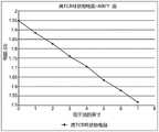
图3是描绘了在不同输入下的电阻响应的示例的曲线图;FIG. 3 is a graph depicting examples of resistance responses at different inputs;
图4是根据本公开的教导的流体传感器系统的控制系统的框图;4 is a block diagram of a control system of a fluid sensor system in accordance with the teachings of the present disclosure;
图5是根据本公开的教导的由流体传感器系统执行的流体监测例程的流程图;5 is a flowchart of a fluid monitoring routine performed by a fluid sensor system in accordance with the teachings of the present disclosure;
图6A、图6B、图6C和图6D示出了根据本公开的教导的用于流体传感器系统的探针的变型;6A, 6B, 6C, and 6D illustrate variations of probes for fluid sensor systems in accordance with the teachings of the present disclosure;
图7A至图7J示出了根据本公开的教导的用于流体传感器系统的探针的电阻加热元件、流体温度传感器和/或环境温度传感器的附加配置;7A-7J illustrate additional configurations of resistive heating elements, fluid temperature sensors, and/or ambient temperature sensors for probes of fluid sensor systems in accordance with the teachings of the present disclosure;
图8示出了根据本公开的教导的具有集成加热器-传感器的加热器系统;8 illustrates a heater system with an integrated heater-sensor in accordance with the teachings of the present disclosure;
图9是根据本公开的教导的第一形式的集成加热器-传感器的局部剖视图;9 is a partial cross-sectional view of a first form of integrated heater-sensor in accordance with the teachings of the present disclosure;
图10是根据本公开的教导的第二形式的集成加热器-传感器的局部剖视图;10 is a partial cross-sectional view of a second form of integrated heater-sensor in accordance with the teachings of the present disclosure;
图11是根据本公开的教导的第三形式的集成加热器-传感器的局部剖视图;以及11 is a partial cross-sectional view of a third form of integrated heater-sensor in accordance with the teachings of the present disclosure; and
图12是图8的加热器系统的加热器控制系统的框图。FIG. 12 is a block diagram of a heater control system of the heater system of FIG. 8 .
本文描述的附图仅用于说明目的,而不旨在以任何方式限制本公开的范围。The drawings described herein are for illustration purposes only and are not intended to limit the scope of the present disclosure in any way.
具体实施方式Detailed ways
以下描述本质上仅是示例性的,并且不旨在限制本公开、应用或用途。应当理解,在所有附图中,相应的附图标记表示相同或相应的部件和特征。The following description is merely exemplary in nature and is not intended to limit the disclosure, application, or uses. It should be understood that throughout the drawings, corresponding reference numerals indicate like or corresponding parts and features.
一种用于加热例如液体的加热系统,通常包括用于测量流体温度和环境温度的多个独立传感器。在一种形式中,加热系统包括用于加热诸如油或废气的流体的加热器,以及基于来自传感器的测量结果控制加热器的操作的加热器控制系统。在一种形式中,本公开涉及一种用于测量加热器系统的多个性能特性的流体传感器系统。性能特性可以包括例如液位、流体温度、环境温度和/或其他合适的信息。A heating system for heating, for example, liquids, typically including multiple independent sensors for measuring fluid temperature and ambient temperature. In one form, the heating system includes a heater for heating a fluid, such as oil or exhaust gas, and a heater control system for controlling operation of the heater based on measurements from sensors. In one form, the present disclosure relates to a fluid sensor system for measuring various performance characteristics of a heater system. Performance characteristics may include, for example, liquid level, fluid temperature, ambient temperature, and/or other suitable information.
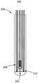
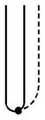
参考图1和图2,现在描述流体传感器系统100的示例。在一种形式中,装置100包括具有有限长度的护套103的探针102和电连接到探针102的控制系统104。探针102放置在流体106中,使得探针102部分地在流体106下方且部分地在其上方,控制系统104配置成控制探针102的操作以测量性能特性。1 and 2, an example of a
探针102包括在护套103内延伸的一个或多个传感器。在一种形式中,护套103由保护性金属合金制成,通常采用镍和铬来防止腐蚀(例如不锈钢、INCOLOY和INCONEL)。在另一种形式中,在低于大约260℃的应用中,传感器120和124可以用塑料绝缘,并且包括用于改进性能的热填充物或灌封。对于高于约260℃的应用,传感器120和124可以保持就位,并通过陶瓷或陶瓷粉末,通常是压实的MgO绝缘。也可使用用于保持传感器120和124的套管/护套的其它合适构造,其在本公开的范围内。例如,感测元件120和124可以由导线、箔或薄膜制成,并且用聚酰亚胺、塑料、陶瓷、玻璃或其它绝缘材料绝缘。
探针102包括流体温度传感器120、环境温度传感器122和电阻加热元件124,以用于测量性能特性,例如流体温度(TFL)、环境温度(TAMB)和液位(L)。在一种形式中,流体温度传感器120和环境温度传感器122提供为热电偶(即,第一热电偶120和第二热电偶122),用于分别测量流体温度和环境温度。作为热电偶,热电偶120和122中的每一个包括由例如镍铝(ALUMEL)和镍铬(CHROMEL)不同材料制成的两个导线(图1中的M1和M2)。导线在一端连接在一起,分别形成接合点J1和J2。为了测量流体温度,接合点J1沿着探针102定位以浸入流体106中,并且为了测量环境温度,接合点J2沿着探针102定位以位于流体的外部。热电偶120和122的导线的另一端分别在端子1261、1262(统称为端子126)和1281、1282(统称为端子128)处电连接到控制系统104。导线可以以各种合适的方式电连接到控制系统104。例如,导线可以经由电源引脚、引线连接到控制系统104内的专用端口,直接连接到控制系统104内的专用端口,和/或经由其他合适的方法连接到控制系统104内的专用端口。The
虽然提供了用于热电偶120和122的材料类型的具体示例,但是可以使用具有不同泽贝克(Seebeck)系数的其它合适的不同材料。例如,可以使用镍合金、铁、康铜、
在操作中,当热电偶120的接合点J1经历温度变化时,在端子1261和1262之间产生电压变化并由控制系统104测量。基于电压和预定数据(例如,参考表),控制系统104确定接合点J1处的温度。热电偶122以与热电偶120类似的方式操作。热电偶120的接合点J1浸入流体106中以测量流体106的温度,热电偶122的接合点J2位于流体106上方以测量环境温度。在下文中,热电偶120可被称为流体热电偶120,而热电偶122可被称为环境热电偶122。In operation, when the junction J1 of the
电阻加热元件124由具有高电阻温度系数(TCR)的材料(例如镍)制成,并测量沿探针102长度的平均温度。电阻加热元件可以被提供为导线、箔和/或薄膜。电阻加热元件124同时受环境温度和流体温度的影响,热电偶120和122独立地受环境温度和流体温度的影响。具体地,电阻加热元件124可以配置为“双线”加热元件,使得其用作加热器和温度传感器。电阻加热元件124通过端子1301和1302(统称为端子130)连接到控制系统102并可由其操作。例如,在与本申请共同转让的美国专利US7,196,295中公开了这种双线能力,该专利的全部内容通过引用并入本文。通常,在端子1301和1302处测量电特性或响应(例如,电压/电流),并且电特性或响应(例如,电压/电流)用于确定电阻加热元件124的电阻。然后,该电阻用于确定液位。具体地,电阻加热元件124的电阻是温度和液位的函数。例如,图2示出了由高TCR环状物检测到的电阻与流体(例如,油)的液位之间的示例相关性,图3示出了由控制系统提供的主动液位感测的预期电阻响应。根据图3的曲线图,电阻响应是在每个温度下与感测环状物的长度成比例的空气和油温度的函数。The
在一种形式中,由电阻元件检测的总电阻进一步在等式1中定义,其中“R1”表示流体上方(例如,沿着L1)的电阻,“R2”表示流体表面周围(例如,沿着L2)的电阻,“R3”表示流体下方的电阻(例如,沿着L3)。在一种形式中,可以使用包括传感器材料性质、传感器几何形状、流体性质、附接方法以及甚至容器材料性质/几何形状的预定义模型来确定液位(即,L2)。电阻R1、R2、和R3中的每一个分别在等式2、3和4中定义。如下所述,R总由控制系统104使用。In one form, the total resistance detected by the resistive element is further defined in
等式1......R总=R1+R2+R3
等式2......R1=f(TAMB,L1)
等式3......R2=f(TAMB,TFL,L2)
等式4......R3=f(TFL+L3)Equation 4...R3 =f(TFL +L3 )
参照图4,控制系统104可通信地连接到加热器控制系统150,该加热器控制系统操作加热器,该加热器加热加热器系统的流体。控制系统104将测量的性能特性传输到加热器控制系统150,加热器控制系统基于该特性控制加热器的操作。在一种形式中,控制系统104包括电源模块152、探针控制模块154、温度模块156、液位模块158和通信模块160。在一种形式中,控制系统104包括电子器件(例如,微处理器、存储器、通信接口、电压-电流转换器、电压-电流测量电路等)和软件程序/算法的组合,所述软件程序/算法存储在存储器中并且可由微处理器执行以执行本文所述的操作。4, the
电源模块152配置成为控制系统104内的电子器件供电,并基于探针102的期望操作状态将指定的功率极限施加到探针102。例如,电源模块152可以包括功率调节器电路(例如,分压器、电压转换器等),用于调节来自电源164的功率并将调节的功率施加到探针102。The
探针控制模块154配置成选择探针102的电阻加热元件的操作状态,并指示电源模块152施加为所选状态分配的指定功率极限。更特别地,在电阻加热元件124提供为双线控制的情况下,元件124作为加热器或传感器操作。为了作为传感器操作,电源模块152将少量功率(例如,0.1mA电流)施加到电阻加热元件124以测量电阻加热元件124的电阻。为了作为加热器操作,电源模块152配置成将发热刺激功率(例如,75W、100W和/或基于系统特性的其他合适的值)施加到电阻加热元件124。加热器状态可以在加热器系统启动时选择,此时流体温度和环境温度基本相同。具体地,流体106具有与空气(α2,α1≠α2)不同的热扩散率(α1)。因此,当流体温度和环境温度相等时,电阻加热元件124作为加热器操作以产生沿探针102的长度的温差,以检测流体的存在。可以施加发热刺激功率一段预设的持续时间和/或直到在部分浸入的探针102上产生温差。一旦检测到流体,加热器系统的加热器开始加热流体是安全的。更特别地,在没有流体或具有少量流体的情况下启动加热器系统的加热器可能损坏加热器。一旦沿着探针的长度检测到适当的温度梯度,探针控制模块154就可将电阻加热元件124作为传感器操作。The
此外,探针控制模块154可指示温度模块156和/或液位模块158测量来自热电偶120和122以及电阻加热元件124的电响应,如下文进一步描述。具体地,在电阻加热元件124作为加热器操作的情况下,探针控制模块154可使温度模块156监测来自热电偶120和122的电响应以确定流体和环境温度。可替代地,在电阻加热元件124作为传感器操作的情况下,探针控制模块154可使温度模块156和/或液位模块158监测来自热电偶120和122和/或电阻加热元件124的电响应。也就是说,在一种形式中,探针控制模块154可以控制探针102以检测热电偶120、热电偶122和电阻加热元件124中的一个或多个的电响应。因此,探针102可仅作为加热器(不测量温度)、作为加热器-传感器(通过元件124加热和通过热电偶120和122测量温度)、或仅作为传感器(不通过电阻加热元件124加热)操作。Additionally,
温度模块156和液位模块158测量来自热电偶120和122以及电阻加热元件124的电响应,并且配置成基于电响应和预定数据来确定性能特性。例如,一个或多个电压-电流测量电路测量端子126、128和130处的电压/电流。温度模块156基于分别在端子126和128上测量的电压以及将测量电压与温度相关联的预定信息来计算流体温度和环境温度。液位模块158测量电阻加热元件124在端子130处的电响应,以确定元件124的总电阻。液位模块158使用电阻、流体温度、环境温度和预定信息(例如,使温度、电阻和液位相关联的查找表和/或算法)确定液位。
通信模块160配置为与外部装置通信,诸如加热器控制系统150和/或用户接口(例如,显示器、键盘、鼠标)。在一种形式中,通信模块160将性能特性传输到加热器控制系统150以控制加热系统。通信模块160还可以将性能特性输出到用户(未示出)可见的显示器。在一种形式中,通信模块160包括用于与加热器控制系统150建立无线通信或有线通信的电子器件,例如收发器。
参考图5,提供了使用本公开的流体传感器系统100测量一个或多个性能特性的流体监测例程170的示例。例程170可以周期性地执行,或者可以由外部装置(例如加热器控制系统150)请求,或由经由例如计算装置可通信地连接到传感器系统的用户请求。5, an example of a
在172,传感器系统100使用流体温度传感器120和环境温度传感器122测量流体温度(TFL)和环境温度(TAMB),在174,传感器系统100确定流体温度是否与环境温度相同。也就是说,传感器系统100确定是否存在温度梯度。如果存在差异,则传感器系统100移动到180。否则,在176,传感器系统100将电阻加热元件124作为加热器操作,并且在178确定是否存在流体。更具体地,在176,电阻加热元件124作为加热器沿着探针的长度(即,探针的浸入流体中并在环境大气中延伸的区域)产生温差,当传感器系统100测量流体温度和环境温度时,该温差由传感器系统验证。At 172 ,
在检测到流体之后,在180,传感器系统100将电阻加热元件124作为传感器操作,然后在182如上所述测量流体温度、环境温度和电阻加热元件的电阻。使用测量值和预定信息,传感器系统100在184确定液位并将性能特性(例如,液位、流体温度和/或环境温度)输出到外部装置。After detecting the fluid, the
传感器系统100可以在保持在本公开的范围内时以其它合适的方式配置,不限于图4的过程。例如,在确定存在流体之后,系统100可以通知加热器控制系统150存在流体并加热流体。在又一变型中,在存在温度梯度的情况下,传感器系统100可通过将低刺激功率(例如,电流0.1mA)施加到电阻加热元件来连续地监测液位。在又一示例中,传感器系统100可在检测流体之后继续将电阻加热元件124作为加热器操作或切断元件124的电力。The
流体传感器系统可以以其他合适的方式配置以测量一个或多个性能特性。例如,图6A、图6B、图6C和图6D示出了用于测量一个或多个性能特性的不同类型的探针。图6A示出了具有探针202和控制系统204的流体传感器系统200。探针202包括流体温度传感器206、用于测量高(最大)极限(例如在特定位置处的最大温度)的极限传感器208、以及电阻加热元件210。在一种形式中,流体温度传感器206是热电偶,其以与流体热电偶120类似的方式配置和操作以测量流体温度。电阻加热元件210以与电阻加热元件124类似的方式配置和操作。代替环境热电偶122,探针202包括极限传感器208,其提供为由具有不同泽贝克系数的两种不同材料(例如,M1和M2)制成的热电偶。The fluid sensor system may be configured in other suitable ways to measure one or more performance characteristics. For example, Figures 6A, 6B, 6C, and 6D illustrate different types of probes used to measure one or more performance characteristics. FIG. 6A shows a
控制系统204电连接到流体温度传感器206、极限传感器208和电阻加热元件210。控制系统204以与控制系统104类似的方式配置来操作探针202,并测量流体温度和液位。更具体地,在一种形式中,控制系统204从例如设置在控制系统内的冷端补偿(CJC)或设置在加热器控制系统150中的温度传感器(未示出)获得环境温度。利用环境温度,控制系统204操作探针202以测量流体温度和/或液位。
此外,控制系统204还配置为基于极限传感器208的输出来确定流体温度是否在预设阈值之外,并且配置为基于高流体温度来执行保护动作。例如,在极限传感器208作为热电偶的情况下,控制系统204的温度模块配置为测量连接到极限传感器208的端子两端的电压变化,并且基于预定数据确定极限传感器208的接合点处的温度(即,诊断温度)。控制系统204可包括将诊断温度与预设温度极限进行比较的诊断模块(未示出)。如果诊断温度高于温度极限,则诊断模块执行保护动作,这可包括经由通信模块160通知加热器控制系统150高流体温度并建议切断加热元件的电力。保护动作还可以是操作连接在电源和加热器系统的加热器(未示出)之间的电源开关(例如继电器)以切断加热器的电力。在保持在本公开的范围内时,还可以实施其他合适的保护动作,例如向操作者的通知。Additionally, the
探针102、202的流体温度传感器可以是其它合适的传感器,并且不应限于热电偶。例如,图6B示出了探针230,其具有极限传感器208和电阻加热元件210。代替热电偶,探针230包括作为流体温度传感器的电阻温度检测器(RTD)232。利用RTD 232,控制系统204的温度模块配置成基于RTD 232所检测的电阻反馈以及将电阻反馈与温度相关联的预定信息来确定流体温度。The fluid temperature sensors of the
利用探针202或探针230,流体传感器系统配置成利用一个传感器装置测量多个性能特性,诸如流体温度、液位和/或诊断温度。因此,降低了向加热器控制系统提供信息的传感器数量的复杂性。Using
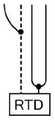
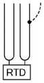
在又一变型中,图6C示出了具有极限传感器208和四线RTD的探针250,其中一个环状物(loop)252由高TCR材料制成以形成电阻加热元件,而第二环状物254由相同材料制成。环状物208形成流体温度传感器。高TCR环状物可以是Balco、镍、铜、钼等。环状物252和254连接至RTD 256,用于提供更精确的电阻测量,以确定液位和流体温度。两个环状物252和254同时用于通过RTD检测流体温度。控制系统配置成通过测量252、254或两者的回路电阻,在通过RTD检测流体温度和流体存在或液位之间快速切换。一个或两个高TCR环状物可用作加热器或传感器,或同时用作加热器和传感器。在图6D所示的另一变型中,探针270不包括极限传感器,而是具有与图6C类似的四线RTD。In yet another variation, Figure 6C shows a
图7A至图7J示出了可在探针中使用以形成流体温度传感器、电阻加热元件和环境温度传感器中的一个或多个的其它导线配置。在图7A至图7J中,虚线表示第一材料(例如,镍铬),实线表示高TCR材料(例如,镍),并且节点示出热电偶接合点。7A-7J illustrate other wire configurations that may be used in a probe to form one or more of a fluid temperature sensor, a resistive heating element, and an ambient temperature sensor. In FIGS. 7A-7J , the dashed line represents the first material (eg, Nichrome), the solid line represents the high TCR material (eg, nickel), and the nodes show thermocouple junctions.
在一种形式中,本公开涉及一种包括探针和控制系统的流体传感器系统。探针的一部分浸入由加热系统加热的流体中。该探针包括电阻加热元件,该电阻加热元件用于确定液位并用于在流体和空气之间产生热梯度。In one form, the present disclosure relates to a fluid sensor system including a probe and a control system. A portion of the probe is immersed in the fluid heated by the heating system. The probe includes a resistive heating element for determining the liquid level and for creating a thermal gradient between the fluid and the air.
如本文所述,流体传感器系统的探针可以以各种合适的方式配置,以至少测量流体温度、液位,并且在流体温度与空气温度相同的情况下提供加热特征。例如,探针可以是具有镍引线的四线矿物绝缘RTD,以测量流体温度和液位,其中集成标准热电偶以测量环境。在这种配置中,RTD具有比热电偶用于流体温度测量的更高的精度。或者,探针可以包括矿物绝缘的镍-镍铬热电偶,其中假定环境是控制系统中的冷端补偿(CJC),则泽贝克效应提供流体的温度,并且镍的高TCR提供液位感测。在这种形式中,减少了设置在探针内的导线的数量。As described herein, the probes of the fluid sensor system can be configured in various suitable ways to measure at least fluid temperature, liquid level, and provide a heating feature if the fluid temperature is the same as the air temperature. For example, the probe can be a four-wire mineral insulated RTD with nickel leads to measure fluid temperature and level, with integrated standard thermocouples to measure the environment. In this configuration, RTDs have higher accuracy than thermocouples for fluid temperature measurement. Alternatively, the probe may comprise a mineral insulated nickel-nickel-chromium thermocouple, where the Seebeck effect provides the temperature of the fluid and the high TCR of nickel provides level sensing assuming the environment is cold junction compensation (CJC) in the control system . In this form, the number of wires disposed within the probe is reduced.
基于前述内容,本公开的流体传感器系统包括有限长度的探针,该探针包括至少一个具有高电阻热系数的电阻加热元件(例如,电阻电路,诸如电阻线、箔、薄膜)和至少一个用于确定流体温度的温度传感器,诸如RTD或热电偶。探针还可以包括用于测量流体上方的环境温度的第二温度传感器,例如RTD或热电偶。Based on the foregoing, fluid sensor systems of the present disclosure include a finite length probe including at least one resistive heating element (eg, a resistive circuit such as resistive wire, foil, film) having a high thermal coefficient of resistance and at least one Temperature sensors, such as RTDs or thermocouples, used to determine fluid temperature. The probe may also include a second temperature sensor, such as an RTD or thermocouple, for measuring the ambient temperature above the fluid.
如本文所述,探针可以以各种合适的方式配置,以至少包括电阻加热元件和流体温度传感器。例如:至少一个导线用于RTD和泽贝克效应温度确定;至少一个导线用于流体温度和液位检测的目的(电阻元件);至少一个导线用于检测流体和环境温度;至少一个导线用于检测环境温度和液位检测;来自四线RTD的引线用于测量液位。As described herein, the probe may be configured in various suitable ways to include at least a resistive heating element and a fluid temperature sensor. For example: at least one lead for RTD and Seebeck effect temperature determination; at least one lead for fluid temperature and level detection purposes (resistive element); at least one lead for fluid and ambient temperature detection; at least one lead for detection Ambient temperature and level detection; leads from a four-wire RTD are used to measure level.
该流体传感器系统还包括控制系统,该控制系统配置成调节功率以提供预定量的功率,例如被施加以加热电阻元件的刺激电流、被施加到电阻元件的低非加热监测电流、和/或如果RTD被包括用于流体温度测量则被施加到RTD的低监测电流。The fluid sensor system also includes a control system configured to regulate power to provide a predetermined amount of power, such as a stimulation current applied to heat the resistive element, a low non-heated monitoring current applied to the resistive element, and/or if RTDs are included for fluid temperature measurement then a low monitoring current is applied to the RTD.
控制系统配置成测量电响应,诸如电阻元件两端的电压、来自热电偶的电压和/或RTD两端的电压。控制系统还配置为将探针的电阻元件操作为:(1)通过将发热刺激电流施加到电阻加热元件以在部分浸没的探针上产生温差的加热器,或(2)如果在流体和周围环境之间已经存在温差,则通过将监测电流(即,刺激电流)施加到电阻加热元件的传感器。将刺激电流施加到电阻元件以感测流体的存在,并且当施加监测电流时电阻元件的响应与流体温度结合用于确定液位。The control system is configured to measure electrical responses, such as the voltage across the resistive element, the voltage from the thermocouple, and/or the voltage across the RTD. The control system is also configured to operate the resistive element of the probe as: (1) a heater by applying a thermal stimulation current to the resistive heating element to create a temperature differential across the partially submerged probe, or (2) if in the fluid and surrounding A temperature difference already exists between the environments, then by applying a monitoring current (ie, stimulation current) to the sensor of the resistive heating element. A stimulation current is applied to the resistive element to sense the presence of the fluid, and the response of the resistive element when the monitoring current is applied is used in conjunction with the fluid temperature to determine the fluid level.
在保持在本公开的范围内时,控制系统可以配置为执行附加操作。例如,控制系统可以存储作为流体历史测量的性能特性,其可以用于形成探针或加热器系统的操作模型。The control system may be configured to perform additional operations while remaining within the scope of the present disclosure. For example, the control system may store performance characteristics as a historical measure of the fluid, which may be used to model the operation of the probe or heater system.
在另一种形式中,本公开涉及一种集成加热器-传感器,用于产生热量且用于测量加热器系统的一个或多个性能特性。因此,在一种形式中,集成加热器-传感器包括至少一个用于产生热量的电阻加热元件和用于测量指定位置处的温度的温度传感器。为了解释的目的,将具有集成加热器-传感器的加热器系统描述为用于加热液体(例如油)的液体加热器系统,并且集成加热器-传感器可操作以测量液位、流体温度中的至少一个作为性能特性。然而,本公开的集成加热器-传感器可以用于其他应用(例如,排气系统、柔性管加热器等),并且不应限于液体加热器系统。另外,如下面进一步描述的,集成加热器-传感器还可用于基于系统特性和预定极限/算法等来确定用于系统的预防性维护调度,或更一般地,确定用于系统的各种维修参数。In another form, the present disclosure relates to an integrated heater-sensor for generating heat and for measuring one or more performance characteristics of a heater system. Thus, in one form, the integrated heater-sensor includes at least one resistive heating element for generating heat and a temperature sensor for measuring the temperature at a designated location. For purposes of explanation, a heater system with an integrated heater-sensor is described as a liquid heater system for heating a liquid (eg, oil), and the integrated heater-sensor is operable to measure at least one of liquid level, fluid temperature One as a performance characteristic. However, the integrated heater-sensor of the present disclosure may be used in other applications (eg, exhaust systems, flexible tube heaters, etc.) and should not be limited to liquid heater systems. Additionally, as described further below, the integrated heater-sensor may also be used to determine preventive maintenance schedules for the system, or more generally, various maintenance parameters for the system based on system characteristics and predetermined limits/algorithms, etc. .
参照图8,加热器系统300包括可作为加热器、传感器或其组合操作的集成加热器-传感器装置302(即集成加热器装置302),以及加热器控制系统304,加热器控制系统配置成基于来自装置302的数据和预定信息来操作集成加热器装置302,预定信息包括但不限于算法、系统模型、预定设定点、查找表等。加热器系统300可操作以加热设置在容器308中的液体306,例如油。更特别地,加热器控制系统302调节来自电源310的功率,以将所需的电功率施加到加热器装置302。基于由加热器装置302测量的一个或多个性能特性来确定施加到加热器装置302的功率量。8,
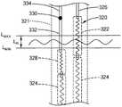
这里,加热器装置302包括由具有不同的TCR的至少两种不同材料限定的至少一个多部分电阻元件。更特别地,在一种形式中,参照图9,加热器装置302配置成包括嵌入在护套321内的多部分电阻元件320。多部分电阻元件320包括总体上由附图标记322标识的第一部分和总体上由附图标记324标识的第二部分324。在一种形式中,第一部分322连接到第一电源引脚326,第二部分322连接到第一部分322并且沿着护套321延伸。Here,
第一部分322由第一导电材料(例如镍)限定,第二部分324由第二导电材料(例如镍铬合金)限定,该第二导电材料具有比第一导电材料低的电阻温度系数(TCR)。更特别地,第一导电材料和第二导电材料都产生热量,但是具有高TCR的第一导电材料由于温度而表现出变化的电阻,因此如本文进一步描述的,第一导电材料进一步用作传感器。虽然提供了用于第一导电材料和第二导电材料的具体示例,但是在保持在本公开的范围内时可以使用其他合适的材料。The
在一种形式中,第一部分322配置成沿着经受温差的指定区域延伸。例如,在图9中,部分322在由最大液位和最小液位(LMax和LMin)限定的液位范围(LR)之间延伸,其中实际液位设置在其间。因此,第一部分322可操作为不仅加热液体302,而且与上述探针类似的方式检测流体的存在,并且如下所述测量液位。In one form, the
在一种形式中,第二部分324配置成当加热器装置302设置在容器308中时完全浸入液体306中。与第一部分322类似,第二部分324可操作为加热液体,但电阻不发生变化。因此,即使在冷启动期间,热部分324的电阻保持基本恒定。在下文中,第一部分和第二部分可以分别被称为液位传感器部分322和加热部分324。In one form, the
通过具有多部分电阻元件,加热器装置302可以表现出以下性质:(1)与整个元件由高TCR材料制成的构造相比,如果多部分电阻元件的一部分由高TCR材料制成,则测量高油位与低油位的电阻变化的比率的信号的强度增加;(2)与整个线圈由高TCR材料制成相比,当使用小段高TCR材料时,与液位变化相关的信号可以从由液体温度变化引起的电阻变化中消除;以及(3)全部高TCR线圈的电阻在室温下(例如,当加热器装置302在空闲周期之后首次启动时)可能是低的,这可在施加设计电压时且直到电阻元件升温到接近工作温度引起高电流时。这种高电流会使电源电路过载。By having a multi-part resistive element, the
在一种形式中,加热器装置302的多部分电阻元件320包括流体温度传感器和/或环境温度传感器。更特别地,多部分电阻元件320包括第三部分,该第三部分总体上由附图标记328标识,并且由具有高TCR的导电材料限定。例如,第三部分328可以由与液位传感器部分322相同的材料制成。第三部分328配置成完全浸入液体306中以在元件320作为传感器操作时测量流体温度。基于第三部分328的电阻的变化确定流体温度,并且由于多部分电阻元件320的大部分由低TCR材料形成,所以与沿着多部分电阻元件320的整个长度的温度分布相关联的误差或模糊量可忽略或至少显著地减少。在下文中,第三部分328可以被称为流体温度传感器部分328。In one form, the multi-part
在一种形式中,多部分电阻元件320连接到位于最大液位上方的热电偶接合点330以测量环境温度。例如,接合点330由第一引脚332和由泽贝克系数与第一引脚332不同的材料制成的第二引脚334限定。这里,第二引脚334还作为连接到加热器控制系统304的另一电源引脚。在一种形式中,第一引脚332由具有与加热部分324的低TCR材料相似或相同的泽贝克系数的材料制成。In one form, the multi-section
作为热电偶的接合点330产生作为温度的函数的电响应(例如,mV信号),并且加热器控制系统304基于预定数据确定温度,预定数据诸如系统模型、预定函数关系和/或将电响应与温度相关联的查找表。这种热电偶(TC)电源引脚在提交于2015年5月29日,名称为“RESISTIVE HEATER WITH TEMPERATURE SENSING POWER PINS”的美国专利申请US14/725,537中公开,该专利与本申请被共同拥有,其内容通过引用并入本文。除了环境温度之外,接合点330处的温度是流体温度、液位和加热器功率的函数。可以如本文所述确定除环境温度之外的值。
基于上述内容,加热器装置302设置为具有多部分电阻元件320,该多部分电阻元件具有液位传感器部分322、流体温度传感器部分328和加热部分324,并且连接到热电偶接合点330以测量环境温度。加热器装置302可以在保持在本公开的范围内时以其它合适的方式配置。例如,参考图10,在一种形式中,除了多部分电阻元件320之外,加热器装置302B还包括至少一个均匀电阻元件340,其平行于多部分电阻元件320延伸并且由低TCR材料制成以产生加热。为了清楚起见,电阻元件320和340都是产生热量的电阻加热元件。然而,与多部分电阻元件320不同,均匀电阻元件340由具有低TCR材料的一种材料制成,并且仅可作为加热器操作;而多部分电阻元件320由不同TCR的多种材料形成以作为加热器或传感器操作。均匀电阻元件340经由电源引脚342和344连接到加热器控制系统304,并且因此,虽然均匀电阻元件与多部分电阻元件320平行延伸,但其是与多部分电阻元件320的电路不同的单独电路。电阻加热元件可以经由导线、箔、薄膜工艺或其它合适的工艺形成。Based on the above,
沿着多部分电阻元件320设置的传感器部分可以分布在多个多部分电阻元件中。例如,图11示出了加热器装置302C,其包括具有液位传感器部分320的第一多部分电阻元件350和具有流体温度传感器部分328的第二多部分电阻元件352。虽然未示出,但加热器320C也可包括一个或多个均匀电阻元件。在另一变型中,本公开的集成加热器-传感器可以不包括本文所述的所有传感器部分。例如,图11的加热器装置302C可以仅包括多部分电阻元件350,而不包括352。The sensor sections disposed along the multi-section
在保持在本公开的范围内时,也可使用集成加热器的其它合适的配置。例如,在一种形式中,热电偶接合点可以设置在均匀电阻元件的电源引脚处,而不是多部分电阻元件处。在另一示例中,代替热电偶接合点,多部分电阻元件可以包括由第一导电材料(即,具有高TCR的材料)制成的部分,该部分位于最大液位之上以测量环境空气的温度并形成环境传感器部分。在一种形式中,第一导电材料的电阻被选择为足够低,以避免在最大占空比、由于加热器操作产生的电流而导致的最大局部产生的功率、以及最大环境温度条件下使加热器的那部分过热。Other suitable configurations of integrated heaters may also be used while remaining within the scope of the present disclosure. For example, in one form, the thermocouple junction may be provided at the power supply pins of the uniform resistive element rather than the multi-section resistive element. In another example, instead of a thermocouple junction, a multi-section resistive element may include a section made of a first conductive material (ie, a material with a high TCR) that sits above the maximum liquid level to measure ambient air temperature and form the environmental sensor part. In one form, the resistance of the first conductive material is selected to be low enough to avoid heating under conditions of maximum duty cycle, maximum locally generated power due to current flow from heater operation, and maximum ambient temperature That part of the appliance is overheating.
基于加热器装置302的配置,加热器控制系统304配置为将加热器装置302作为例如加热器、加热器-传感器或传感器操作。参照图12,在一种形式中,加热器控制系统304包括加热器控制模块380、性能特性模块382和电源模块384。加热器控制模块380配置成控制加热器装置302的操作(例如,作为加热器、传感器、加热器-传感器或关闭状态)。例如,如果加热器装置302包括至少一个多部分电阻元件320和至少一个均匀电阻元件或至少两个多部分电阻元件320,则加热器装置302可作为加热器、加热器-传感器、和传感器操作。可替代地,如果加热器装置302包括一个多部分电阻元件,则加热器装置302可作为加热器或传感器操作。Based on the configuration of
作为加热器,加热器控制模块380具有施加到多部分电阻元件320和/或均匀电阻元件的第一功率水平(例如,75瓦、100+瓦或基于系统特性的其它合适的功率)。作为传感器,加热器控制模块380操作加热器装置,以通过将少量功率(即,刺激功率)施加到多部分电阻元件320(例如,0.1mA电流)来检测多部分电阻元件320中的至少一个的电特性。在一种形式中,作为传感器,加热器控制模块302将刺激功率施加到多部分电阻元件中的至少一个,并且不将功率施加到均匀电阻元件和/或其他的多部分电阻元件。作为加热器-传感器,加热器控制模块380配置为将低刺激功率施加到多部分电阻元件中的至少一个,并且将第一功率水平施加到均匀电阻元件和/或其他的多部分电阻元件。As a heater, the
在一种形式中,加热器控制模块380可以基于预定的循环程序在各种操作状态(例如,加热器、传感器、加热器-传感器、关闭状态)之间切换(例如,每5分钟作为传感器/加热器-传感器操作,然后作为加热器操作)。可以使用其它合适的控制方案来使加热器控制模块380在不同状态之间切换。In one form, the
类似于传感器系统的电源模块152,电源模块152配置成向加热器控制系统304内的电子器件供电,并基于由加热器控制模块380确定的加热器装置302的选定操作,向加热器装置302施加指定的功率极限。例如,电源模块152可以包括功率调节器电路(例如,分压器、电压转换器等),以用于调节来自电源164的功率并将调节的功率施加到探针102和加热器装置302。Similar to the
使用加热器的电响应,性能特性模块382计算加热器装置302的一个或多个性能特性,并将计算出的值提供给加热器控制模块380,以控制加热器装置302。例如,液位是在已知或预定功率水平下的电阻变化幅度和电阻的时间变化率的函数。因此,性能特性模块382使用系统模型、函数关系(例如,预定算法)或查找表来确定液位,该查找表基于电阻变化和时间变化率值将液位映射到电阻变化。电响应是由系统定义的物理特性(几何形状、材料等)的函数。Using the electrical response of the heater, the
在保持在本公开的范围内时,加热器控制系统304可以配置为执行其他操作。例如,在一种形式中,加热器控制系统304可以与外部装置通信,外部装置诸如计算装置、显示器、键盘、按钮、触摸屏等,用于从用户接收数据和/或用于显示关于加热器系统的信息。例如,加热器控制系统304可以经由外部装置接收温度设定点、用于控制加热器的操作状态的命令和/或其他信息。反过来,加热器控制系统可以显示例如图形用户界面,该图形用户界面示出可选择的命令、加热器的当前操作状态、当前流体温度、液位、质量和/或其他合适的信息。The
在一种形式中,具有感测能力的集成加热器可以实施为虚拟感测系统的一部分,以在不使用附加传感器的情况下确定加热系统的参数。例如,具有本公开的集成加热器-传感器的虚拟感测系统可以用于确定参数,例如:(1)流体储存器温度,(2)流体储存器液位,和(3)流体储存器质量,其中至少一个加热器维持系统中流体的温度、液位和质量。在共同未决的申请中提供了一种这样的虚拟感测系统,该申请为于2017年3月2日提交的,名称为“VIRTUAL SENSING SYSTEM”的美国申请US15/447,942,其与本申请被共同拥有,并且其全部内容通过引用并入本文。该申请描述了一种用于设置在排气系统中的加热系统的虚拟感测系统。通常,控制系统配置为基于一组已知变量和预定算法来计算加热系统的一个或多个值。使用加热系统的计算值和物理特性,控制系统控制加热器。这种控制系统可以实施用于流体加热系统,在该流体加热系统中加热液体,例如油。In one form, an integrated heater with sensing capabilities may be implemented as part of a virtual sensing system to determine parameters of the heating system without the use of additional sensors. For example, a virtual sensing system with an integrated heater-sensor of the present disclosure can be used to determine parameters such as: (1) fluid reservoir temperature, (2) fluid reservoir level, and (3) fluid reservoir mass, At least one of the heaters maintains the temperature, level and quality of the fluid in the system. One such virtual sensing system is provided in co-pending application US 15/447,942, filed March 2, 2017, entitled "VIRTUAL SENSING SYSTEM," which is Commonly owned and incorporated herein by reference in its entirety. This application describes a virtual sensing system for a heating system provided in an exhaust system. Typically, the control system is configured to calculate one or more values of the heating system based on a set of known variables and a predetermined algorithm. Using the calculated values and physical properties of the heating system, the control system controls the heater. Such a control system can be implemented for a fluid heating system in which a liquid, such as oil, is heated.
例如,对于本公开的加热系统,如果三个其他参数中的至少两个是已知的,则虚拟感测系统可以用于确定流体温度、液位和/或流体质量。例如:如果流体储存器液位和质量已知,则可以确定流体储存器温度;如果流体储存器温度和质量已知,则可以确定流体储存器液位;以及如果流体储存器温度和液位已知,则可以确定流体质量。For example, with the heating system of the present disclosure, if at least two of the three other parameters are known, the virtual sensing system can be used to determine fluid temperature, level, and/or fluid quality. For example: if the fluid reservoir level and mass are known, the fluid reservoir temperature can be determined; if the fluid reservoir temperature and mass are known, the fluid reservoir level can be determined; and if the fluid reservoir temperature and level have been know, the fluid quality can be determined.
在实施虚拟感测系统时,在一种形式中,本公开的加热器控制系统配置成接收来自以下各项之中的至少一个输入:液位、流体质量、从加热系统的物理特性导出的参数及其组合。该至少一个输入还包括到加热器系统的加热器的功率输入和系统输入中的至少一个。物理特性可以包括,例如,电阻丝直径、MgO(绝缘)厚度、护套厚度、电导率、构造材料的比热和密度、传热系数、加热器和流体管道的发射率,以及其他几何和应用相关信息。In implementing the virtual sensing system, in one form, the heater control system of the present disclosure is configured to receive input from at least one of: liquid level, fluid quality, parameters derived from physical characteristics of the heating system and its combinations. The at least one input also includes at least one of a power input to a heater of the heater system and a system input. Physical properties can include, for example, resistance wire diameter, MgO (insulation) thickness, jacket thickness, electrical conductivity, specific heat and density of materials of construction, heat transfer coefficients, emissivity of heaters and fluid conduits, and other geometries and applications Related Information.
在一种形式中,在加热器具有护套的情况下,控制系统配置成基于从加热系统的物理特性导出的参数来确定加热器的护套温度(Ts)。可替代地,加热器可以是具有加热器表面温度的分层加热器,并且加热器控制系统配置成通过例如以下等式确定加热器表面温度(Ts),其中:In one form, where the heater has a jacket, the control system is configured to determine the jacket temperature (Ts ) of the heater based on parameters derived from physical characteristics of the heating system. Alternatively, the heater may be a layered heater having a heater surface temperature, and the heater control system is configured to determine the heater surface temperature (Ts ) by, for example, the following equation, where:

cs为加热器护套材料的比热cs is the specific heat of the heater sheath material
ms为护套材料的重量ms is the weight of the sheath material
Ts为护套材料的温度Ts is the temperature of the sheath material
Tv为流体(油缸)的温度Tv is the temperature of the fluid (cylinder)
T1为MgO绝缘材料的温度T1 is the temperatureof the MgO insulating material
D1为MgO绝缘材料的厚度D1 is the thicknessof the MgO insulating material
DS为护套材料的厚度DS is the thickness of the sheath material
K1为MgO材料的热阻率K1 is the thermal resistivityof the MgO material
A1为MgO材料的横截面面积A1 is the cross-sectional areaof the MgO material
kS为护套材料的热阻率kS is the thermal resistivity of the sheath material
As为护套的横截面面积As is the cross-sectional area of the sheath
hC1为护套的对流系数hC1 is the convection coefficient of the sheath
AV1为暴露于护套的流体(油缸)的横截面面积AV1 is the cross-sectional area of the fluid (cylinder) exposed to the jacket
加热器控制系统还可以配置成根据加热系统的物理特性计算流体温度(Tv),并且可以通过例如以下等式来确定Tv:The heater control system can also be configured to calculate the fluid temperature (Tv ) based on the physical characteristics of the heating system, and Tv can be determined by, for example, the following equation:

cv为流体储存器的比热cv is the specific heat of the fluid reservoir
mv是流体储存器的重量mv is the weight of the fluid reservoir
Ts为护套材料的温度Ts is the temperature of the sheath material
Tv为流体(油缸)的温度Tv is the temperature of the fluid (cylinder)
Tab为环境温度Tab is the ambient temperature
DS为护套材料的厚度DS is the thickness of the sheath material
K1为MgO材料的热阻率K1 is the thermal resistivityof the MgO material
A1为MgO材料的横截面面积A1 is the cross-sectional areaof the MgO material
kS为护套材料的热阻率kS is the thermal resistivity of the sheath material
As为护套的横截面面积As is the cross-sectional area of the sheath
hC1为护套的对流系数hC1 is the convection coefficient of the sheath
AV1为暴露于护套的流体(油缸)的横截面面积AV1 is the cross-sectional area of the fluid (cylinder) exposed to the jacket
henv为流体储存器对环境的对流系数henv is the convection coefficient of the fluid reservoir to the environment
Aenv为流体储存器暴露于环境的横截面面积Aenv is the cross-sectional area of the fluid reservoir exposed to the environment
因此,从加热系统的物理特性导出的参数可以确定护套温度(Ts)和流体温度(Tv)中的至少一个。流体温度(Tv)可以从本公开的集成加热器和/或本公开的流体传感器系统获得,如本文所述。利用虚拟感测系统,本公开的加热器控制系统可操作以在没有特定传感器的情况下预测与加热器相关联的温度和与流体相关联的温度。应当注意,其它等式可以用作虚拟感测系统的一部分,并且不应当限于所提供的等式。Accordingly, parameters derived from the physical properties of the heating system can determine at least one of the jacket temperature (Ts ) and the fluid temperature (Tv ). The fluid temperature (Tv ) can be obtained from the integrated heater of the present disclosure and/or the fluid sensor system of the present disclosure, as described herein. Using the virtual sensing system, the heater control system of the present disclosure is operable to predict the temperature associated with the heater and the temperature associated with the fluid without specific sensors. It should be noted that other equations may be used as part of the virtual sensing system and should not be limited to the equations provided.
加热器控制系统可基于加热器几何形状、输入功率、高TCR元件电阻、具有系统性质的热电偶电源引脚、油温和系统模型中的至少一个来确定加热器护套温度。或者,TCR和功率映射一起可用于计算护套温度。这些方法提供了如下益处:诸如在瞬时中更快地加热液体而不烧焦、增强的安全性、与传感器被连接的情况相比增加的温度感测准确性、增加的液体寿命、以及减少过度加热液体等。The heater control system may determine the heater jacket temperature based on at least one of heater geometry, input power, high TCR element resistance, thermocouple power pins with system properties, oil temperature and system model. Alternatively, the TCR and power mapping together can be used to calculate the jacket temperature. These methods provide benefits such as faster heating of the liquid in an instant without scorching, enhanced safety, increased temperature sensing accuracy compared to where the sensor is connected, increased liquid life, and reduced overshoot Heating liquids, etc.
在本公开的一种形式中,加热器控制系统配置为执行自校准以校准加热系统。自校准包括在冷却之后测量流体温度以使用,例如,TC电源引脚系统的冷端补偿传感器、小的表面安装RTD或印刷电路板(PCB)上的热敏电阻中的至少一个来获得室温下的稳定状态。在测量稳定状态室温之后,控制系统将精确测量的功率脉冲施加到加热器。测量的功率脉冲应当足够短,以使得温度响应独立于流体储存器中的流体量。接着,将观察的时间-温度响应与形成流体加热系统时(例如在工厂校准期间或在安装流体加热系统期间)测量的预定时间-温度响应进行比较。通过比较时间-温度响应,例如在峰值温度或在预定时间段之后以及在升高的温度(除了室温点之外)获得第二校准点。在一种形式中,电阻斜率响应也可以用于代替或附加于第二校准点。In one form of the present disclosure, the heater control system is configured to perform a self-calibration to calibrate the heating system. Self-calibration involves measuring fluid temperature after cooling to obtain room temperature using, for example, at least one of a cold junction compensation sensor of a TC power pin system, a small surface mount RTD, or a thermistor on a printed circuit board (PCB) stable state. After measuring the steady state room temperature, the control system applies precisely measured power pulses to the heater. The measured power pulses should be short enough to make the temperature response independent of the amount of fluid in the fluid reservoir. Next, the observed time-temperature response is compared to a predetermined time-temperature response measured when the fluid heating system is formed (eg, during factory calibration or during installation of the fluid heating system). A second calibration point is obtained by comparing the time-temperature response, eg, at peak temperature or after a predetermined period of time and at elevated temperature (in addition to the room temperature point). In one form, the resistance slope response may also be used in place of or in addition to the second calibration point.
对于自校准过程,代替等待室温下的稳定状态,测量来自加热器的温度变化率信号(即,电阻或毫伏的变化率),并且使用系统模型来推断信号将稳定到什么稳定状态。然后,将变化率校准到例如PCB处的室温测量值。For the self-calibration process, instead of waiting for a steady state at room temperature, measure the temperature rate signal (ie, the rate of change of resistance or millivolts) from the heater, and use the system model to infer to what steady state the signal will stabilize. The rate of change is then calibrated to, for example, room temperature measurements at the PCB.
在另一种形式中,自校准包括等待直到储存器是空的,将导线加热到居里点以上,以及测量在最大TCR斜率(TCR曲线的导数)的点处的电阻。在一个示例中,如果镍用作高TCR材料,则最大TCR斜率点是358.2℃。校准还包括使用来自功率突发的电阻作为潜在的第二校准点。In another form, self-calibration includes waiting until the reservoir is empty, heating the wire above the Curie point, and measuring the resistance at the point of maximum TCR slope (derivative of the TCR curve). In one example, if nickel is used as a high TCR material, the maximum TCR slope point is 358.2°C. Calibration also includes using the resistance from the power burst as a potential second calibration point.
在另一自校准中,校准点提供为校准点的镍铬电阻的局部最大值(例如,镍铬合金80的550℃)。校准包括等待直到储存器是空的,例如,在过滤或清洁之后,将导线加热到550℃。接着,用高电流刺激加热器,使得导线达到550℃并且护套保持较冷。该护套应该低于液体的闪点,以抑制导线上的高应力并增加加热器的寿命。In another self-calibration, the calibration point is provided as the local maximum of the Nichrome resistance at the calibration point (eg, 550°C for Nichrome 80). Calibration involves waiting until the reservoir is empty, eg, after filtering or cleaning, heating the wire to 550°C. Next, the heater is stimulated with high current so that the wire reaches 550°C and the sheath remains cooler. The jacket should be below the flash point of the liquid to suppress high stress on the wires and increase the life of the heater.
单独的液体温度传感器也可用于自校准。具体地,校准包括等待加热器温度达到与液体的平衡温度,使用单独的液体温度传感器在若干温度下校准,以及使用先验信息来推断上述液体温度的上限。A separate liquid temperature sensor is also available for self-calibration. Specifically, calibration includes waiting for the heater temperature to reach equilibrium temperature with the liquid, calibrating at several temperatures using a separate liquid temperature sensor, and using a priori information to infer the upper limit of the above liquid temperature.
在保持在本公开的范围内时,其它特征/步骤可以用于自校准。例如,以下可以用于自校准:具有独特可调性质如拐点或峰斜率的镍-铁合金;以及诸如启动或在受控冷却期间的功率对电阻响应历史输入;至少一个加热器电路的预定的和可预测的漂移特性可用于消除对现场校准的需要。自校准调节可以在加热系统的寿命期间内周期性地发生。Other features/steps may be used for self-calibration while remaining within the scope of the present disclosure. For example, the following can be used for self-calibration: nickel-iron alloys with unique tunable properties such as inflection point or peak slope; and historical inputs such as power versus resistance response during startup or during controlled cooling; predetermined sums of at least one heater circuit Predictable drift characteristics can be used to eliminate the need for field calibration. Self-calibration adjustments may occur periodically over the life of the heating system.
在一种形式中,控制系统还可以配置成包括用于防止对加热器系统的物理损坏或其它不可预见的影响的系统模型。例如,系统模型配置成预测与各种操作状态相关联的温度的时间变化率或用于测试能量脉冲(例如,在施加测量的能量脉冲之前将加热器冷却到低于目标设定点几度并且观察响应)温度的时间变化率。超出预期范围的电阻或mV变化可能意味着存在问题,并且可以以某种其他方式生成或使用警报或错误代码来促成关于是否允许继续操作的决定。In one form, the control system may also be configured to include a system model for preventing physical damage to the heater system or other unforeseen effects. For example, the system model is configured to predict the time rate of change of temperature associated with various operating states or for testing energy pulses (eg, cooling a heater to a few degrees below a target set point before applying a measured energy pulse and Observe the time rate of change in response) temperature. A change in resistance or mV outside the expected range could indicate a problem, and an alarm or error code could be generated or used in some other way to facilitate a decision on whether to allow continued operation.
关于自校准和虚拟感测特征,可以通过使用系统模型使流体温度与CJC匹配,该系统模型可以是具有参数的指数衰减方程,该参数将根据冷却速率随时间的变化来确定,并且将用于推断最终的稳定状态温度。如果室温不是恒定的,则可能需要更复杂的模型。例如,CJC或小的、便宜的、PCB安装的传感器可以用于测量室温,并且系统模型然后可以基于冷却速率确定流体和房间之间的温差,从而提供用于校准流体或加热器温度感测特征的温度。Regarding the self-calibration and virtual sensing features, the fluid temperature can be matched to the CJC by using a system model, which can be an exponential decay equation with parameters that will be determined from the cooling rate over time and will be used for Infer the final steady state temperature. If the room temperature is not constant, a more complex model may be required. For example, a CJC or a small, inexpensive, PCB-mounted sensor can be used to measure room temperature, and a system model can then determine the temperature difference between the fluid and the room based on the cooling rate, providing a sensing feature for calibrating fluid or heater temperature temperature.
本公开的流体传感器系统和具有集成加热器-传感器的加热器系统可以减少用于加热器系统的独立传感器的数量。本文所述的虚拟感测特征可实施为具有流体传感器系统和/或具有集成加热器-传感器的加热器系统的一部分。The fluid sensor system and heater system with an integrated heater-sensor of the present disclosure can reduce the number of separate sensors for the heater system. The virtual sensing features described herein may be implemented as part of a heater system with a fluid sensor system and/or with an integrated heater-sensor.
应当注意,本公开不限于作为示例描述和示出的实施方式。已经描述了多种修改,并且更多的修改是本领域技术人员的知识的一部分。这些和进一步的修改以及技术等同物的任何替换可以添加到说明书和附图,而不脱离本公开和本专利的保护范围。It should be noted that the present disclosure is not limited to the embodiments described and illustrated as examples. Various modifications have been described, and many more are part of the knowledge of those skilled in the art. These and further modifications and any substitution of technical equivalents may be added to the description and drawings without departing from the scope of protection of this disclosure and this patent.
Claims (9)
Priority Applications (1)
| Application Number | Priority Date | Filing Date | Title |
|---|---|---|---|
| CN202211039578.9ACN115468626A (en) | 2017-07-27 | 2018-07-27 | Sensor system and integrated heater-sensor for measuring and controlling heater system performance |
Applications Claiming Priority (3)
| Application Number | Priority Date | Filing Date | Title |
|---|---|---|---|
| US201762537922P | 2017-07-27 | 2017-07-27 | |
| US62/537,922 | 2017-07-27 | ||
| PCT/US2018/044119WO2019023594A1 (en) | 2017-07-27 | 2018-07-27 | Sensor system and integrated heater-sensor for measuring and controlling performance of a heater system |
Related Child Applications (1)
| Application Number | Title | Priority Date | Filing Date |
|---|---|---|---|
| CN202211039578.9ADivisionCN115468626A (en) | 2017-07-27 | 2018-07-27 | Sensor system and integrated heater-sensor for measuring and controlling heater system performance |
Publications (2)
| Publication Number | Publication Date |
|---|---|
| CN111108350A CN111108350A (en) | 2020-05-05 |
| CN111108350Btrue CN111108350B (en) | 2022-09-16 |
Family
ID=63165562
Family Applications (2)
| Application Number | Title | Priority Date | Filing Date |
|---|---|---|---|
| CN202211039578.9APendingCN115468626A (en) | 2017-07-27 | 2018-07-27 | Sensor system and integrated heater-sensor for measuring and controlling heater system performance |
| CN201880059920.7AActiveCN111108350B (en) | 2017-07-27 | 2018-07-27 | Sensor systems and integrated heater-sensors for measuring and controlling heater system performance |
Family Applications Before (1)
| Application Number | Title | Priority Date | Filing Date |
|---|---|---|---|
| CN202211039578.9APendingCN115468626A (en) | 2017-07-27 | 2018-07-27 | Sensor system and integrated heater-sensor for measuring and controlling heater system performance |
Country Status (7)
| Country | Link |
|---|---|
| US (3) | US11525744B2 (en) |
| EP (2) | EP4075105B1 (en) |
| JP (1) | JP7252194B2 (en) |
| CN (2) | CN115468626A (en) |
| CA (1) | CA3071112A1 (en) |
| TW (2) | TWI707141B (en) |
| WO (1) | WO2019023594A1 (en) |
Families Citing this family (23)
| Publication number | Priority date | Publication date | Assignee | Title |
|---|---|---|---|---|
| US11540358B2 (en)* | 2015-05-29 | 2022-12-27 | Watlow Electric Manufacturing Company | Modular heater assembly with interchangeable auxiliary sensing junctions |
| US11408779B2 (en) | 2019-06-03 | 2022-08-09 | Daily Thermetrics Corporation | Temperature sensor and methods of use |
| CN115211228A (en) | 2020-02-24 | 2022-10-18 | 沃特洛电气制造公司 | Dynamic calibration of control system for controlling heater |
| CN113639829A (en)* | 2020-05-11 | 2021-11-12 | 罗伯特·博世有限公司 | Method for monitoring liquid level of vehicle liquid tank, storage medium, control unit and SCR system |
| JP7731373B2 (en)* | 2020-05-19 | 2025-08-29 | ワトロー エレクトリック マニュファクチュアリング カンパニー | Passive and active calibration methods for resistive heaters |
| CN112067080B (en)* | 2020-07-13 | 2023-04-28 | 重庆材料研究院有限公司 | Method for continuously measuring liquid level in real time in high-temperature and high-pressure environment |
| US11650106B2 (en)* | 2020-12-30 | 2023-05-16 | Rosemount Inc. | Temperature probe with improved response time |
| KR102504842B1 (en)* | 2020-12-31 | 2023-02-28 | 주식회사 케이티앤지 | Aerosol generating device and operation method thereof |
| US20220221194A1 (en)* | 2021-01-14 | 2022-07-14 | Gabriel Ayers | "off" state monitoring for conservation override apparatus and method |
| CN113043750B (en)* | 2021-02-23 | 2022-08-02 | 珠海艾派克微电子有限公司 | Liquid level sensing device and method, consumable verification method and print cartridge |
| US11819163B2 (en) | 2021-03-02 | 2023-11-21 | Henny Penny Corporation | Staged fryer heating system |
| US12098916B1 (en)* | 2021-03-22 | 2024-09-24 | The United States Of America, As Represented By The Secretary Of The Navy | Temperature sensing arrayal for freeboard detection |
| US11678769B2 (en) | 2021-04-29 | 2023-06-20 | Henny Penny Corporation | Automated cooking system and methods of managing basket workflow for food preparation |
| US12262847B2 (en) | 2021-04-29 | 2025-04-01 | Henny Penny Corporation | Automated cooking system and method using basket-gantry interface |
| US11668595B1 (en)* | 2021-09-10 | 2023-06-06 | Consolidated Nuclear Security, LLC | Fluid level and conductivity sensor for high temperature applications |
| US20230152140A1 (en)* | 2021-11-18 | 2023-05-18 | Emerson Electric Co. | Systems and methods for tank level monitoring |
| US20230340952A1 (en)* | 2021-11-21 | 2023-10-26 | Industrial Flow Solutions Operating, Llc | Submersible pump contaminant detection system |
| KR20230144270A (en)* | 2022-04-07 | 2023-10-16 | 한온시스템 주식회사 | Fluid heating heater and driving control method there of |
| CN114877533B (en)* | 2022-06-07 | 2024-10-29 | 温岭琅优电子科技有限公司 | Water level detector for intelligent closestool water temperature heating water tank and detection method thereof |
| US20240418577A1 (en)* | 2023-06-15 | 2024-12-19 | Goodrich Corporation | Dual-use level and temperature probe |
| CN117204621A (en)* | 2023-09-05 | 2023-12-12 | 爱奇迹(香港)有限公司 | Atomization component, atomization device, control method and readable storage medium |
| US12385669B2 (en)* | 2023-09-15 | 2025-08-12 | Robert L. Bullick | Water heater for heating water using various power sources and enhancing energy savings |
| CN120161884B (en)* | 2025-03-25 | 2025-09-16 | 山东汇能新材料科技股份有限公司 | Reactor bed temperature control method and system |
Citations (4)
| Publication number | Priority date | Publication date | Assignee | Title |
|---|---|---|---|---|
| GB2168153A (en)* | 1984-12-06 | 1986-06-11 | Hopkinsons Ltd | Liquid level control and indication |
| US4994780A (en)* | 1988-05-02 | 1991-02-19 | Fluid Components, Inc. | Heated extended resistance temperature sensor, apparatus for sensing and method of making same |
| US5134772A (en)* | 1988-05-02 | 1992-08-04 | Fluid Components, Inc. | Method of making a U-shaped heated extended resistance temperature sensor |
| CN104568053A (en)* | 2014-12-11 | 2015-04-29 | 中国核电工程有限公司 | Self-heating differential thermoresistor liquid level sensor and liquid level measurement method thereof |
Family Cites Families (34)
| Publication number | Priority date | Publication date | Assignee | Title |
|---|---|---|---|---|
| JPS6039510A (en)* | 1983-08-12 | 1985-03-01 | Ngk Insulators Ltd | Liquid level detecting element |
| JPS63139216A (en)* | 1986-12-01 | 1988-06-11 | Mitsubishi Electric Corp | Oil surface detection system |
| US4785665A (en)* | 1987-01-16 | 1988-11-22 | Mcculloch Reg W | Measuring instrument that senses heat transfer along a probe |
| JPS63200482A (en)* | 1987-02-16 | 1988-08-18 | 浜 律雄 | Control circuit of ceramic heater |
| JPH05114460A (en)* | 1991-10-21 | 1993-05-07 | Chichibu Cement Co Ltd | Heating apparatus |
| JPH06324750A (en)* | 1993-05-10 | 1994-11-25 | Arco Giken:Kk | Temperature controller for heater and parts thereof |
| JPH10185652A (en)* | 1996-12-24 | 1998-07-14 | Japan Organo Co Ltd | Device for detecting drop of liquid level |
| JP3787958B2 (en)* | 1997-06-18 | 2006-06-21 | 松下電器産業株式会社 | Water heater |
| JP3369933B2 (en)* | 1997-11-06 | 2003-01-20 | リンナイ株式会社 | Water detection method |
| JP2000009518A (en)* | 1998-06-26 | 2000-01-14 | Harman Co Ltd | Gas/liquid decision device |
| GB9816645D0 (en) | 1998-07-30 | 1998-09-30 | Otter Controls Ltd | Improvements relating to electrically heated water boiling vessels |
| US6202486B1 (en) | 1998-10-01 | 2001-03-20 | Imaging & Sensing Technology Corporation | Analog liquid level sensor |
| US6098457A (en) | 1999-01-18 | 2000-08-08 | Cts Corporation | Fluid level detector using thermoresistive sensor |
| US6331212B1 (en)* | 2000-04-17 | 2001-12-18 | Avansys, Llc | Methods and apparatus for thermally processing wafers |
| CN100516507C (en) | 2002-05-14 | 2009-07-22 | 日本特殊陶业株式会社 | Glow plug control component and glow plug |
| JP4047762B2 (en)* | 2002-05-14 | 2008-02-13 | 日本特殊陶業株式会社 | Glow plug control device |
| JP2004008253A (en)* | 2002-06-03 | 2004-01-15 | Hoshizaki Electric Co Ltd | Fryer |
| JP4356867B2 (en)* | 2003-02-05 | 2009-11-04 | 株式会社山武 | Temperature sensor |
| GB2401183B (en) | 2003-04-29 | 2006-10-18 | Terence Mcburney | Probe |
| US7196295B2 (en)* | 2003-11-21 | 2007-03-27 | Watlow Electric Manufacturing Company | Two-wire layered heater system |
| DE102004026396B4 (en)* | 2004-05-29 | 2007-10-31 | Itw Automotive Products Gmbh & Co. Kg | Device for measuring the level height and / or the temperature in a container |
| US8536496B2 (en)* | 2004-09-15 | 2013-09-17 | Watlow Electric Manufacturing Company | Adaptable layered heater system |
| US7458718B2 (en) | 2006-02-22 | 2008-12-02 | Honeywell International Inc. | Temperature sensor that achieves a fast response in an exhaust gas environment |
| US7804296B2 (en)* | 2007-10-05 | 2010-09-28 | Schlumberger Technology Corporation | Methods and apparatus for monitoring a property of a formation fluid |
| US8267578B2 (en) | 2009-02-04 | 2012-09-18 | Schlumberger Technology Corporation | Methods and systems for temperature compensated temperature measurements |
| CA2806274C (en)* | 2010-07-22 | 2017-01-17 | Watlow Electric Manufacturing Company | Combination fluid sensor system |
| IT1401525B1 (en)* | 2010-08-13 | 2013-07-26 | Isanik S R L | SENSOR DEVICE TO MEASURE THE FLOW AND / OR THE LEVEL OF A FLUID OR A SUBSTANCE PRESENT IN A CONTAINER. |
| GB2491806B (en)* | 2011-05-25 | 2013-07-10 | Microvisk Ltd | Apparatus and method for measuring properties of a fluid |
| CN104575640A (en)* | 2014-12-11 | 2015-04-29 | 中国核电工程有限公司 | Spent fuel water tank liquid level and temperature measuring device |
| US10728956B2 (en)* | 2015-05-29 | 2020-07-28 | Watlow Electric Manufacturing Company | Resistive heater with temperature sensing power pins |
| JP2017015648A (en)* | 2015-07-06 | 2017-01-19 | 日機装株式会社 | Liquid detector |
| US9826574B2 (en)* | 2015-10-28 | 2017-11-21 | Watlow Electric Manufacturing Company | Integrated heater and sensor system |
| EP3423689A1 (en) | 2016-03-02 | 2019-01-09 | Watlow Electric Manufacturing Company | Virtual sensing system |
| CN106768160B (en)* | 2017-03-10 | 2023-06-13 | 中国第一汽车股份有限公司 | Electric heating type urea liquid level sensor |
- 2018
- 2018-07-27CNCN202211039578.9Apatent/CN115468626A/enactivePending
- 2018-07-27EPEP22170811.8Apatent/EP4075105B1/enactiveActive
- 2018-07-27TWTW107126184Apatent/TWI707141B/ennot_activeIP Right Cessation
- 2018-07-27EPEP18753013.4Apatent/EP3658867B1/enactiveActive
- 2018-07-27USUS16/047,702patent/US11525744B2/enactiveActive
- 2018-07-27JPJP2020503943Apatent/JP7252194B2/enactiveActive
- 2018-07-27TWTW108132393Apatent/TWI690706B/ennot_activeIP Right Cessation
- 2018-07-27WOPCT/US2018/044119patent/WO2019023594A1/ennot_activeCeased
- 2018-07-27CACA3071112Apatent/CA3071112A1/enactivePending
- 2018-07-27CNCN201880059920.7Apatent/CN111108350B/enactiveActive
- 2022
- 2022-12-13USUS18/080,381patent/US12135147B2/enactiveActive
- 2024
- 2024-11-04USUS18/936,077patent/US20250060133A1/enactivePending
Patent Citations (4)
| Publication number | Priority date | Publication date | Assignee | Title |
|---|---|---|---|---|
| GB2168153A (en)* | 1984-12-06 | 1986-06-11 | Hopkinsons Ltd | Liquid level control and indication |
| US4994780A (en)* | 1988-05-02 | 1991-02-19 | Fluid Components, Inc. | Heated extended resistance temperature sensor, apparatus for sensing and method of making same |
| US5134772A (en)* | 1988-05-02 | 1992-08-04 | Fluid Components, Inc. | Method of making a U-shaped heated extended resistance temperature sensor |
| CN104568053A (en)* | 2014-12-11 | 2015-04-29 | 中国核电工程有限公司 | Self-heating differential thermoresistor liquid level sensor and liquid level measurement method thereof |
Also Published As
| Publication number | Publication date |
|---|---|
| TWI707141B (en) | 2020-10-11 |
| JP7252194B2 (en) | 2023-04-04 |
| JP2020529010A (en) | 2020-10-01 |
| TWI690706B (en) | 2020-04-11 |
| CN115468626A (en) | 2022-12-13 |
| TW201947218A (en) | 2019-12-16 |
| US11525744B2 (en) | 2022-12-13 |
| EP3658867A1 (en) | 2020-06-03 |
| CA3071112A1 (en) | 2019-01-31 |
| CN111108350A (en) | 2020-05-05 |
| US20230116575A1 (en) | 2023-04-13 |
| EP4075105B1 (en) | 2024-12-25 |
| WO2019023594A1 (en) | 2019-01-31 |
| EP4075105A1 (en) | 2022-10-19 |
| US20250060133A1 (en) | 2025-02-20 |
| EP3658867B1 (en) | 2022-07-06 |
| US12135147B2 (en) | 2024-11-05 |
| TW201910761A (en) | 2019-03-16 |
| US20190032958A1 (en) | 2019-01-31 |
Similar Documents
| Publication | Publication Date | Title |
|---|---|---|
| CN111108350B (en) | Sensor systems and integrated heater-sensors for measuring and controlling heater system performance | |
| CN107852778B (en) | Resistive heater with temperature sensing power pin | |
| JP7374922B2 (en) | Resistive heater with temperature sensing power pin and auxiliary sensing junction | |
| JP2019516207A5 (en) | ||
| JP2022526020A (en) | Thermal system with temperature limiting device | |
| WO2010045221A1 (en) | Temperature monitoring and control system for negative temperature coefficient heaters | |
| JP2012507069A (en) | Adaptive temperature controller | |
| KR20200129119A (en) | Control system for heater control | |
| US11096248B2 (en) | Resistive heater with temperature sensing power pins and auxiliary sensing junction | |
| EP4154680B1 (en) | Passive and active calibration methods for a resistive heater | |
| US20240053209A1 (en) | Thermometer with a diagnostic function | |
| KR200399623Y1 (en) | Non-magnetic field heating wire used in bedding | |
| Moreira et al. | Sensors characterization and control of measurement systems based on thermoresistive sensors via feedback linearization | |
| HK1131851A1 (en) | Adaptive temperature controller |
Legal Events
| Date | Code | Title | Description |
|---|---|---|---|
| PB01 | Publication | ||
| PB01 | Publication | ||
| SE01 | Entry into force of request for substantive examination | ||
| SE01 | Entry into force of request for substantive examination | ||
| GR01 | Patent grant | ||
| GR01 | Patent grant |