CN111095876B - Method, medium, and apparatus for creating virtual networks across multiple public clouds - Google Patents
Method, medium, and apparatus for creating virtual networks across multiple public cloudsDownload PDFInfo
- Publication number
- CN111095876B CN111095876BCN201880058539.9ACN201880058539ACN111095876BCN 111095876 BCN111095876 BCN 111095876BCN 201880058539 ACN201880058539 ACN 201880058539ACN 111095876 BCN111095876 BCN 111095876B
- Authority
- CN
- China
- Prior art keywords
- tenant
- mfn
- public cloud
- address
- virtual
- Prior art date
- Legal status (The legal status is an assumption and is not a legal conclusion. Google has not performed a legal analysis and makes no representation as to the accuracy of the status listed.)
- Active
Links
Images


Classifications
- H—ELECTRICITY
- H04—ELECTRIC COMMUNICATION TECHNIQUE
- H04L—TRANSMISSION OF DIGITAL INFORMATION, e.g. TELEGRAPHIC COMMUNICATION
- H04L63/00—Network architectures or network communication protocols for network security
- H04L63/02—Network architectures or network communication protocols for network security for separating internal from external traffic, e.g. firewalls
- H04L63/0227—Filtering policies
- H04L63/0263—Rule management
- H—ELECTRICITY
- H04—ELECTRIC COMMUNICATION TECHNIQUE
- H04L—TRANSMISSION OF DIGITAL INFORMATION, e.g. TELEGRAPHIC COMMUNICATION
- H04L12/00—Data switching networks
- H04L12/02—Details
- H04L12/14—Charging, metering or billing arrangements for data wireline or wireless communications
- H—ELECTRICITY
- H04—ELECTRIC COMMUNICATION TECHNIQUE
- H04L—TRANSMISSION OF DIGITAL INFORMATION, e.g. TELEGRAPHIC COMMUNICATION
- H04L12/00—Data switching networks
- H04L12/02—Details
- H04L12/14—Charging, metering or billing arrangements for data wireline or wireless communications
- H04L12/1403—Architecture for metering, charging or billing
- H—ELECTRICITY
- H04—ELECTRIC COMMUNICATION TECHNIQUE
- H04L—TRANSMISSION OF DIGITAL INFORMATION, e.g. TELEGRAPHIC COMMUNICATION
- H04L12/00—Data switching networks
- H04L12/02—Details
- H04L12/14—Charging, metering or billing arrangements for data wireline or wireless communications
- H04L12/1428—Invoice generation, e.g. customization, lay-out, database processing, algorithms for calculating the bill or formatting invoices as WWW pages
- H—ELECTRICITY
- H04—ELECTRIC COMMUNICATION TECHNIQUE
- H04L—TRANSMISSION OF DIGITAL INFORMATION, e.g. TELEGRAPHIC COMMUNICATION
- H04L12/00—Data switching networks
- H04L12/28—Data switching networks characterised by path configuration, e.g. LAN [Local Area Networks] or WAN [Wide Area Networks]
- H04L12/2854—Wide area networks, e.g. public data networks
- H04L12/2856—Access arrangements, e.g. Internet access
- H04L12/2858—Access network architectures
- H04L12/2859—Point-to-point connection between the data network and the subscribers
- H—ELECTRICITY
- H04—ELECTRIC COMMUNICATION TECHNIQUE
- H04L—TRANSMISSION OF DIGITAL INFORMATION, e.g. TELEGRAPHIC COMMUNICATION
- H04L12/00—Data switching networks
- H04L12/28—Data switching networks characterised by path configuration, e.g. LAN [Local Area Networks] or WAN [Wide Area Networks]
- H04L12/40—Bus networks
- H04L12/403—Bus networks with centralised control, e.g. polling
- H—ELECTRICITY
- H04—ELECTRIC COMMUNICATION TECHNIQUE
- H04L—TRANSMISSION OF DIGITAL INFORMATION, e.g. TELEGRAPHIC COMMUNICATION
- H04L12/00—Data switching networks
- H04L12/28—Data switching networks characterised by path configuration, e.g. LAN [Local Area Networks] or WAN [Wide Area Networks]
- H04L12/46—Interconnection of networks
- H04L12/4633—Interconnection of networks using encapsulation techniques, e.g. tunneling
- H—ELECTRICITY
- H04—ELECTRIC COMMUNICATION TECHNIQUE
- H04L—TRANSMISSION OF DIGITAL INFORMATION, e.g. TELEGRAPHIC COMMUNICATION
- H04L12/00—Data switching networks
- H04L12/28—Data switching networks characterised by path configuration, e.g. LAN [Local Area Networks] or WAN [Wide Area Networks]
- H04L12/46—Interconnection of networks
- H04L12/4641—Virtual LANs, VLANs, e.g. virtual private networks [VPN]
- H—ELECTRICITY
- H04—ELECTRIC COMMUNICATION TECHNIQUE
- H04L—TRANSMISSION OF DIGITAL INFORMATION, e.g. TELEGRAPHIC COMMUNICATION
- H04L12/00—Data switching networks
- H04L12/66—Arrangements for connecting between networks having differing types of switching systems, e.g. gateways
- H—ELECTRICITY
- H04—ELECTRIC COMMUNICATION TECHNIQUE
- H04L—TRANSMISSION OF DIGITAL INFORMATION, e.g. TELEGRAPHIC COMMUNICATION
- H04L41/00—Arrangements for maintenance, administration or management of data switching networks, e.g. of packet switching networks
- H04L41/04—Network management architectures or arrangements
- H04L41/046—Network management architectures or arrangements comprising network management agents or mobile agents therefor
- H—ELECTRICITY
- H04—ELECTRIC COMMUNICATION TECHNIQUE
- H04L—TRANSMISSION OF DIGITAL INFORMATION, e.g. TELEGRAPHIC COMMUNICATION
- H04L41/00—Arrangements for maintenance, administration or management of data switching networks, e.g. of packet switching networks
- H04L41/08—Configuration management of networks or network elements
- H04L41/0803—Configuration setting
- H—ELECTRICITY
- H04—ELECTRIC COMMUNICATION TECHNIQUE
- H04L—TRANSMISSION OF DIGITAL INFORMATION, e.g. TELEGRAPHIC COMMUNICATION
- H04L41/00—Arrangements for maintenance, administration or management of data switching networks, e.g. of packet switching networks
- H04L41/08—Configuration management of networks or network elements
- H04L41/0895—Configuration of virtualised networks or elements, e.g. virtualised network function or OpenFlow elements
- H—ELECTRICITY
- H04—ELECTRIC COMMUNICATION TECHNIQUE
- H04L—TRANSMISSION OF DIGITAL INFORMATION, e.g. TELEGRAPHIC COMMUNICATION
- H04L43/00—Arrangements for monitoring or testing data switching networks
- H04L43/08—Monitoring or testing based on specific metrics, e.g. QoS, energy consumption or environmental parameters
- H04L43/0823—Errors, e.g. transmission errors
- H04L43/0829—Packet loss
- H—ELECTRICITY
- H04—ELECTRIC COMMUNICATION TECHNIQUE
- H04L—TRANSMISSION OF DIGITAL INFORMATION, e.g. TELEGRAPHIC COMMUNICATION
- H04L43/00—Arrangements for monitoring or testing data switching networks
- H04L43/08—Monitoring or testing based on specific metrics, e.g. QoS, energy consumption or environmental parameters
- H04L43/0852—Delays
- H—ELECTRICITY
- H04—ELECTRIC COMMUNICATION TECHNIQUE
- H04L—TRANSMISSION OF DIGITAL INFORMATION, e.g. TELEGRAPHIC COMMUNICATION
- H04L43/00—Arrangements for monitoring or testing data switching networks
- H04L43/08—Monitoring or testing based on specific metrics, e.g. QoS, energy consumption or environmental parameters
- H04L43/0876—Network utilisation, e.g. volume of load or congestion level
- H04L43/0888—Throughput
- H—ELECTRICITY
- H04—ELECTRIC COMMUNICATION TECHNIQUE
- H04L—TRANSMISSION OF DIGITAL INFORMATION, e.g. TELEGRAPHIC COMMUNICATION
- H04L45/00—Routing or path finding of packets in data switching networks
- H04L45/02—Topology update or discovery
- H04L45/04—Interdomain routing, e.g. hierarchical routing
- H—ELECTRICITY
- H04—ELECTRIC COMMUNICATION TECHNIQUE
- H04L—TRANSMISSION OF DIGITAL INFORMATION, e.g. TELEGRAPHIC COMMUNICATION
- H04L45/00—Routing or path finding of packets in data switching networks
- H04L45/12—Shortest path evaluation
- H—ELECTRICITY
- H04—ELECTRIC COMMUNICATION TECHNIQUE
- H04L—TRANSMISSION OF DIGITAL INFORMATION, e.g. TELEGRAPHIC COMMUNICATION
- H04L45/00—Routing or path finding of packets in data switching networks
- H04L45/14—Routing performance; Theoretical aspects
- H—ELECTRICITY
- H04—ELECTRIC COMMUNICATION TECHNIQUE
- H04L—TRANSMISSION OF DIGITAL INFORMATION, e.g. TELEGRAPHIC COMMUNICATION
- H04L45/00—Routing or path finding of packets in data switching networks
- H04L45/64—Routing or path finding of packets in data switching networks using an overlay routing layer
- H—ELECTRICITY
- H04—ELECTRIC COMMUNICATION TECHNIQUE
- H04L—TRANSMISSION OF DIGITAL INFORMATION, e.g. TELEGRAPHIC COMMUNICATION
- H04L45/00—Routing or path finding of packets in data switching networks
- H04L45/74—Address processing for routing
- H—ELECTRICITY
- H04—ELECTRIC COMMUNICATION TECHNIQUE
- H04L—TRANSMISSION OF DIGITAL INFORMATION, e.g. TELEGRAPHIC COMMUNICATION
- H04L45/00—Routing or path finding of packets in data switching networks
- H04L45/74—Address processing for routing
- H04L45/745—Address table lookup; Address filtering
- H—ELECTRICITY
- H04—ELECTRIC COMMUNICATION TECHNIQUE
- H04L—TRANSMISSION OF DIGITAL INFORMATION, e.g. TELEGRAPHIC COMMUNICATION
- H04L61/00—Network arrangements, protocols or services for addressing or naming
- H04L61/09—Mapping addresses
- H04L61/25—Mapping addresses of the same type
- H—ELECTRICITY
- H04—ELECTRIC COMMUNICATION TECHNIQUE
- H04L—TRANSMISSION OF DIGITAL INFORMATION, e.g. TELEGRAPHIC COMMUNICATION
- H04L61/00—Network arrangements, protocols or services for addressing or naming
- H04L61/09—Mapping addresses
- H04L61/25—Mapping addresses of the same type
- H04L61/2503—Translation of Internet protocol [IP] addresses
- H04L61/2514—Translation of Internet protocol [IP] addresses between local and global IP addresses
- H—ELECTRICITY
- H04—ELECTRIC COMMUNICATION TECHNIQUE
- H04L—TRANSMISSION OF DIGITAL INFORMATION, e.g. TELEGRAPHIC COMMUNICATION
- H04L61/00—Network arrangements, protocols or services for addressing or naming
- H04L61/09—Mapping addresses
- H04L61/25—Mapping addresses of the same type
- H04L61/2503—Translation of Internet protocol [IP] addresses
- H04L61/255—Maintenance or indexing of mapping tables
- H—ELECTRICITY
- H04—ELECTRIC COMMUNICATION TECHNIQUE
- H04L—TRANSMISSION OF DIGITAL INFORMATION, e.g. TELEGRAPHIC COMMUNICATION
- H04L61/00—Network arrangements, protocols or services for addressing or naming
- H04L61/45—Network directories; Name-to-address mapping
- H04L61/4505—Network directories; Name-to-address mapping using standardised directories; using standardised directory access protocols
- H04L61/4511—Network directories; Name-to-address mapping using standardised directories; using standardised directory access protocols using domain name system [DNS]
- H—ELECTRICITY
- H04—ELECTRIC COMMUNICATION TECHNIQUE
- H04L—TRANSMISSION OF DIGITAL INFORMATION, e.g. TELEGRAPHIC COMMUNICATION
- H04L63/00—Network architectures or network communication protocols for network security
- H04L63/02—Network architectures or network communication protocols for network security for separating internal from external traffic, e.g. firewalls
- H04L63/0227—Filtering policies
- H04L63/0245—Filtering by information in the payload
- H—ELECTRICITY
- H04—ELECTRIC COMMUNICATION TECHNIQUE
- H04L—TRANSMISSION OF DIGITAL INFORMATION, e.g. TELEGRAPHIC COMMUNICATION
- H04L63/00—Network architectures or network communication protocols for network security
- H04L63/02—Network architectures or network communication protocols for network security for separating internal from external traffic, e.g. firewalls
- H04L63/0272—Virtual private networks
- H—ELECTRICITY
- H04—ELECTRIC COMMUNICATION TECHNIQUE
- H04L—TRANSMISSION OF DIGITAL INFORMATION, e.g. TELEGRAPHIC COMMUNICATION
- H04L63/00—Network architectures or network communication protocols for network security
- H04L63/02—Network architectures or network communication protocols for network security for separating internal from external traffic, e.g. firewalls
- H04L63/0281—Proxies
- H—ELECTRICITY
- H04—ELECTRIC COMMUNICATION TECHNIQUE
- H04L—TRANSMISSION OF DIGITAL INFORMATION, e.g. TELEGRAPHIC COMMUNICATION
- H04L63/00—Network architectures or network communication protocols for network security
- H04L63/02—Network architectures or network communication protocols for network security for separating internal from external traffic, e.g. firewalls
- H04L63/029—Firewall traversal, e.g. tunnelling or, creating pinholes
- H—ELECTRICITY
- H04—ELECTRIC COMMUNICATION TECHNIQUE
- H04L—TRANSMISSION OF DIGITAL INFORMATION, e.g. TELEGRAPHIC COMMUNICATION
- H04L63/00—Network architectures or network communication protocols for network security
- H04L63/20—Network architectures or network communication protocols for network security for managing network security; network security policies in general
- H—ELECTRICITY
- H04—ELECTRIC COMMUNICATION TECHNIQUE
- H04L—TRANSMISSION OF DIGITAL INFORMATION, e.g. TELEGRAPHIC COMMUNICATION
- H04L67/00—Network arrangements or protocols for supporting network services or applications
- H04L67/01—Protocols
- H04L67/10—Protocols in which an application is distributed across nodes in the network
- H04L67/104—Peer-to-peer [P2P] networks
- H—ELECTRICITY
- H04—ELECTRIC COMMUNICATION TECHNIQUE
- H04L—TRANSMISSION OF DIGITAL INFORMATION, e.g. TELEGRAPHIC COMMUNICATION
- H04L67/00—Network arrangements or protocols for supporting network services or applications
- H04L67/50—Network services
- H—ELECTRICITY
- H04—ELECTRIC COMMUNICATION TECHNIQUE
- H04M—TELEPHONIC COMMUNICATION
- H04M15/00—Arrangements for metering, time-control or time indication ; Metering, charging or billing arrangements for voice wireline or wireless communications, e.g. VoIP
- H—ELECTRICITY
- H04—ELECTRIC COMMUNICATION TECHNIQUE
- H04M—TELEPHONIC COMMUNICATION
- H04M15/00—Arrangements for metering, time-control or time indication ; Metering, charging or billing arrangements for voice wireline or wireless communications, e.g. VoIP
- H04M15/51—Arrangements for metering, time-control or time indication ; Metering, charging or billing arrangements for voice wireline or wireless communications, e.g. VoIP for resellers, retailers or service providers
- G—PHYSICS
- G06—COMPUTING OR CALCULATING; COUNTING
- G06F—ELECTRIC DIGITAL DATA PROCESSING
- G06F9/00—Arrangements for program control, e.g. control units
- G06F9/06—Arrangements for program control, e.g. control units using stored programs, i.e. using an internal store of processing equipment to receive or retain programs
- G06F9/44—Arrangements for executing specific programs
- G06F9/455—Emulation; Interpretation; Software simulation, e.g. virtualisation or emulation of application or operating system execution engines
- G06F9/45533—Hypervisors; Virtual machine monitors
- G06F9/45558—Hypervisor-specific management and integration aspects
- G06F2009/45562—Creating, deleting, cloning virtual machine instances
- G—PHYSICS
- G06—COMPUTING OR CALCULATING; COUNTING
- G06F—ELECTRIC DIGITAL DATA PROCESSING
- G06F9/00—Arrangements for program control, e.g. control units
- G06F9/06—Arrangements for program control, e.g. control units using stored programs, i.e. using an internal store of processing equipment to receive or retain programs
- G06F9/44—Arrangements for executing specific programs
- G06F9/455—Emulation; Interpretation; Software simulation, e.g. virtualisation or emulation of application or operating system execution engines
- G06F9/45533—Hypervisors; Virtual machine monitors
- G06F9/45558—Hypervisor-specific management and integration aspects
- G06F2009/45587—Isolation or security of virtual machine instances
- H—ELECTRICITY
- H04—ELECTRIC COMMUNICATION TECHNIQUE
- H04L—TRANSMISSION OF DIGITAL INFORMATION, e.g. TELEGRAPHIC COMMUNICATION
- H04L2101/00—Indexing scheme associated with group H04L61/00
- H04L2101/30—Types of network names
- H04L2101/35—Types of network names containing special prefixes
- H—ELECTRICITY
- H04—ELECTRIC COMMUNICATION TECHNIQUE
- H04L—TRANSMISSION OF DIGITAL INFORMATION, e.g. TELEGRAPHIC COMMUNICATION
- H04L2212/00—Encapsulation of packets
- H—ELECTRICITY
- H04—ELECTRIC COMMUNICATION TECHNIQUE
- H04L—TRANSMISSION OF DIGITAL INFORMATION, e.g. TELEGRAPHIC COMMUNICATION
- H04L41/00—Arrangements for maintenance, administration or management of data switching networks, e.g. of packet switching networks
- H04L41/40—Arrangements for maintenance, administration or management of data switching networks, e.g. of packet switching networks using virtualisation of network functions or resources, e.g. SDN or NFV entities
- H—ELECTRICITY
- H04—ELECTRIC COMMUNICATION TECHNIQUE
- H04L—TRANSMISSION OF DIGITAL INFORMATION, e.g. TELEGRAPHIC COMMUNICATION
- H04L43/00—Arrangements for monitoring or testing data switching networks
- H04L43/08—Monitoring or testing based on specific metrics, e.g. QoS, energy consumption or environmental parameters
- H—ELECTRICITY
- H04—ELECTRIC COMMUNICATION TECHNIQUE
- H04L—TRANSMISSION OF DIGITAL INFORMATION, e.g. TELEGRAPHIC COMMUNICATION
- H04L61/00—Network arrangements, protocols or services for addressing or naming
- H04L61/09—Mapping addresses
- H04L61/25—Mapping addresses of the same type
- H04L61/2503—Translation of Internet protocol [IP] addresses
- H04L61/256—NAT traversal
- H04L61/2567—NAT traversal for reachability, e.g. inquiring the address of a correspondent behind a NAT server
Landscapes
- Engineering & Computer Science (AREA)
- Computer Networks & Wireless Communication (AREA)
- Signal Processing (AREA)
- Computer Security & Cryptography (AREA)
- Computer Hardware Design (AREA)
- Computing Systems (AREA)
- General Engineering & Computer Science (AREA)
- Environmental & Geological Engineering (AREA)
- Databases & Information Systems (AREA)
- General Business, Economics & Management (AREA)
- Business, Economics & Management (AREA)
- Data Exchanges In Wide-Area Networks (AREA)
- Ultra Sonic Daignosis Equipment (AREA)
- Optical Radar Systems And Details Thereof (AREA)
- Details Of Aerials (AREA)
- Position Fixing By Use Of Radio Waves (AREA)
- Radar Systems Or Details Thereof (AREA)
Abstract
Translated fromChinese
Description
Translated fromChinese背景技术Background technique
如今,公司企业网络是安全地连接公司的不同办公室和部的通信骨干。这种网络通常是广域网(WAN),它连接(1)分支机构和区域园区中的用户、(2)托管业务应用、内联网及其对应数据的公司数据中心,以及(3)通过公司防火墙和DMZ(非军事区)的全球因特网。企业网络包括专用硬件,诸如交换机、路由器和通过昂贵的租用线(诸如帧中继和MPLS(多协议标签交换))互连的中间盒设备。Today, a corporate enterprise network is the communications backbone that securely connects a company's different offices and departments. This network is typically a wide area network (WAN) that connects (1) users in branch offices and regional campuses, (2) corporate data centers hosting business applications, the intranet and its corresponding data, and (3) through corporate firewalls and Global Internet in the DMZ (demilitarized zone). Enterprise networks include specialized hardware such as switches, routers, and middlebox devices interconnected by expensive leased lines such as Frame Relay and MPLS (Multi-Protocol Label Switching).
在最近几年中,公司服务和消费通信服务的方式发生了范式转变。首先,移动性革命已允许用户使用移动设备(主要是智能电话)随时随地访问服务。此类用户通过公共因特网和蜂窝网络访问业务服务。同时,第三方SaaS(软件即服务)供应商(例如,Salesforce、Workday、Zendesk)已取代了传统的本地应用,而托管在私有数据中心中的其它应用已重定位到公共云。虽然这种流量仍在企业网络内承载,但其中很大一部分是在企业网络周边之外发起和终止的并且必须穿越公共因特网(一次或两次)以及企业网络两者。最近的研究表明,有40%的公司网络报告回传流量(即在公司网络中观察到的因特网流量)所占的百分比超过80%。这意味着公司流量的大部分都在昂贵的租用线和消费者因特网上承载。In recent years, there has been a paradigm shift in the way companies serve and consume communication services. First, the mobility revolution has allowed users to access services anytime, anywhere using mobile devices (mainly smartphones). Such users access business services through the public Internet and cellular networks. Meanwhile, third-party SaaS (software as a service) providers (eg, Salesforce, Workday, Zendesk) have replaced traditional on-premises applications, while other applications hosted in private data centers have been relocated to the public cloud. While this traffic is still carried within the corporate network, a significant portion of it originates and terminates outside the corporate network perimeter and must traverse both the public Internet (once or twice) and the corporate network. Recent research shows that 40% of corporate networks report backhaul traffic (ie, Internet traffic observed in corporate networks) as a percentage of over 80%. This means that the bulk of corporate traffic is carried over expensive leased lines and the consumer Internet.
作为以消费者为中心的服务,因特网本身是业务流量的坏媒介。它缺乏关键业务应用所预期的可靠性、QoS(服务质量)保证和安全性。而且,不断增长的消费者流量需求、网络中立法规以及主要参与者(例如,Netflix、Google、公共云)创建的因特网绕过技术降低了每个流量单位的货币回报。这些趋势降低了服务提供者迅速赶上消费者需求并提供适当的业务服务的动机。As a consumer-centric service, the Internet itself is a bad medium for business traffic. It lacks the reliability, QoS (Quality of Service) guarantees and security expected by mission-critical applications. Also, growing consumer traffic demands, net neutrality regulations, and Internet bypassing technologies created by major players (eg, Netflix, Google, public cloud) have reduced the monetary return per unit of traffic. These trends reduce the incentive for service providers to quickly catch up with consumer demand and provide appropriate business services.
鉴于公共云的增长,公司正在将其更多的计算基础设施迁移到公共云数据中心。公共云提供者一直处于计算和联网基础设施投资的前沿。这些云服务已在全球范围内建立了许多数据中心,Azure、AWS、 IBM和Google在2016分别扩展到了38、16、25和14个全球区域。每个公共云提供者都使用昂贵的高速网络来互连自己的数据中心,这些高速网络采用由潜艇部署的暗光纤和海底电缆。Given the growth of public cloud, companies are migrating more of their computing infrastructure to public cloud data centers. Public cloud providers have been at the forefront of computing and networking infrastructure investments. These cloud services have established many data centers around the world, with Azure, AWS, IBM and Google expanding to 38, 16, 25 and 14 global regions respectively in 2016. Each public cloud provider interconnects its data centers using expensive high-speed networks using dark fiber and undersea cables deployed by submarines.
如今,虽然进行了这些改变,但是公司网络策略常常强制所有公司流量通过其安全的WAN网关。随着用户变得移动并且应用迁移到 SaaS和公共云,公司WAN的绕道成本变高,这减慢了所有公司通信的速度。大多数公司WAN的流量都或者来自因特网或者发往因特网。通过因特网发送这种流量的替代安全方案由于性能差且不可靠而不够用。Today, despite these changes, corporate network policies often force all corporate traffic to pass through its secure WAN gateway. As users become mobile and applications migrate to SaaS and public clouds, corporate WAN detours become expensive, slowing down all corporate communications. Most corporate WAN traffic comes either from or to the Internet. Alternative security solutions for sending this traffic over the Internet are insufficient due to poor performance and unreliability.
发明内容SUMMARY OF THE INVENTION
一些实施例在一个或多个区域(例如,若干城市、州、国家等) 中的一个或多个公共云提供者的若干公共云数据中心上为实体建立虚拟网络。可以为其建立这种虚拟网络的实体的示例包括商业实体(例如,公司)、非营利实体(例如,医院、研究机构等)和教育实体(例如,大学、学院等)或任何其它类型的实体。公共云提供者的示例包括Amazon WebServices(AWS)、Google Cloud Platform (GCP)、Microsoft Azure等。Some embodiments establish virtual networks for entities on several public cloud data centers of one or more public cloud providers in one or more regions (eg, several cities, states, countries, etc.). Examples of entities for which such a virtual network may be established include commercial entities (eg, corporations), non-profit entities (eg, hospitals, research institutes, etc.) and educational entities (eg, universities, colleges, etc.) or any other type of entity . Examples of public cloud providers include Amazon Web Services (AWS), Google Cloud Platform (GCP), Microsoft Azure, etc.
在一些实施例中,高速、可靠的私有网络互连公共云数据中心 (公共云)中的两个或更多个。一些实施例将虚拟网络定义为跨越若干公共云以互连私有网络(例如,实体的分支、部(division)、部门(department)或其相关联的数据中心内的网络)、移动用户、 SaaS(软件即服务)提供者的机器、(一个或多个)公共云中的机器和/或服务、以及其它web应用中的一者或多者的覆盖网络。In some embodiments, a high-speed, reliable private network interconnects two or more of the public cloud data centers (public clouds). Some embodiments define a virtual network as spanning several public clouds to interconnect private networks (eg, networks within branches, divisions, departments, or their associated data centers of entities), mobile users, SaaS ( Software as a Service) provider's machines, machines and/or services in public cloud(s), and an overlay network of one or more of other web applications.
在一些实施例中,虚拟网络可以被配置为优化实体的数据消息到其目的地的路由,以获得最佳的端到端性能、可靠性和安全性,同时尝试最小化通过因特网的这种流量的路由。而且,在一些实施例中,虚拟网络可以被配置为优化通过网络的数据消息流的层4处理。例如,在一些实施例中,虚拟网络通过跨连接路径拆分速率控制机制来优化 TCP(传输控制协议)连接的端到端速率。In some embodiments, a virtual network may be configured to optimize the routing of an entity's data messages to their destinations for optimal end-to-end performance, reliability, and security, while attempting to minimize such traffic through the Internet route. Also, in some embodiments, the virtual network may be configured to optimize layer 4 processing of data message flow through the network. For example, in some embodiments, the virtual network optimizes the end-to-end rate of TCP (Transmission Control Protocol) connections by splitting rate control mechanisms across connection paths.
一些实施例通过配置在若干公共云中部署的若干部件来建立虚拟网络。在一些实施例中,这些部件包括基于软件的测量代理、软件转发元件(例如,软件路由器、交换机、网关等)、层4连接代理和中间盒服务机器(例如,设备、VM、容器等)。在一些实施例中,这些部件中的一个或多个使用标准化或通常可用的解决方案,诸如 Open vSwitch、Open VPN、strong Swan和Ryu。Some embodiments establish a virtual network by configuring several components deployed in several public clouds. In some embodiments, these components include software-based measurement agents, software forwarding elements (eg, software routers, switches, gateways, etc.), layer 4 connectivity agents, and middlebox service machines (eg, devices, VMs, containers, etc.). In some embodiments, one or more of these components use standardized or commonly available solutions such as Open vSwitch, Open VPN, strong Swan, and Ryu.
一些实施例利用逻辑上集中的控制器集群(例如,一个或多个控制器服务器的集合),其配置公共云部件以在若干公共云上实现虚拟网络。在一些实施例中,这个集群中的控制器位于各种不同的位置 (例如,位于不同的公共云数据中心中),以便改善冗余性和高可用性。在一些实施例中,控制器集群按比例扩展或收缩用于建立虚拟网络的公共云部件的数量或分配给这些部件的计算或网络资源的数量。Some embodiments utilize a logically centralized controller cluster (eg, a collection of one or more controller servers) that configures public cloud components to implement a virtual network on several public clouds. In some embodiments, the controllers in this cluster are located in various locations (eg, in different public cloud data centers) to improve redundancy and high availability. In some embodiments, the controller cluster scales up or down the number of public cloud components used to establish the virtual network or the amount of computing or network resources allocated to these components.
一些实施例在相同公共云提供者的相同公共云集合上和/或在相同或不同公共云提供者的不同公共云集合上为不同实体建立不同的虚拟网络。在一些实施例中,虚拟网络提供者提供软件和服务,该软件和服务允许不同的租户在相同或不同的公共云上定义不同的虚拟网络。在一些实施例中,相同的控制器集群或不同的控制器集群可以被用于配置公共云部件,以针对若干不同实体在相同或不同的公共云集合上实现不同的虚拟网络。Some embodiments establish different virtual networks for different entities on the same set of public clouds of the same public cloud provider and/or on different sets of public clouds of the same or different public cloud providers. In some embodiments, the virtual network provider provides software and services that allow different tenants to define different virtual networks on the same or different public clouds. In some embodiments, the same controller cluster or different controller clusters may be used to configure public cloud components to implement different virtual networks on the same or different sets of public clouds for several different entities.
为了在一个或多个公共云上为租户部署虚拟网络,控制器集群 (1)基于租户的分支机构、数据中心、移动用户和SaaS提供者的位置来识别用于进入和离开租户的虚拟网络的可能入口和出口路由器,以及(2)识别通过实现虚拟网络的其它中间公共云路由器从识别出的入口路由器遍历到识别出的出口路由器的路由。在识别出这些路由之后,控制器集群将这些路由传播到(一个或多个)公共云中虚拟网络路由器的转发表。在使用基于OVS的虚拟网络路由器的实施例中,控制器通过使用OpenFlow来分发路由。To deploy a virtual network for a tenant on one or more public clouds, the controller cluster (1) identifies the virtual network used to enter and leave the tenant's virtual network based on the location of the tenant's branch offices, data centers, mobile users, and SaaS providers. Possibly ingress and egress routers, and (2) identify routes traversed from the identified ingress router to the identified egress router through other intermediate public cloud routers implementing the virtual network. After identifying these routes, the controller cluster propagates these routes to the forwarding tables of the virtual network routers in the public cloud(s). In an embodiment using an OVS-based virtual network router, the controller distributes routes using OpenFlow.
前面的发明内容旨在用作本发明的一些实施例的简要介绍。它并不意味着是本文档中公开的所有发明性主题的介绍或概述。以下的具体实施方式和在具体实施方式中引用的附图说明将进一步描述在发明内容中描述的实施例以及其它实施例。因而,为了理解本文档描述的所有实施例,需要对发明内容、具体实施方式、附图说明和权利要求书的全面回顾。而且,要求保护的主题不受发明内容、具体实施方式和附图说明中的说明性细节的限制。The foregoing summary is intended to serve as a brief introduction to some embodiments of the present invention. It is not intended to be an introduction or overview of all inventive subject matter disclosed in this document. The following detailed description and the accompanying drawings referenced in the detailed description further describe the embodiments described in this summary, as well as other embodiments. Thus, in order to understand all of the embodiments described in this document, a comprehensive review of the Summary, Detailed Description, Brief Description of the Drawings, and Claims is required. Furthermore, the claimed subject matter is not to be limited by the illustrative details in the Summary, Detailed Description, and Brief Description of the Drawings.
附图说明Description of drawings
在所附权利要求书中阐述了本发明的新颖特征。但是,出于解释的目的,在以下附图中阐述本发明的若干实施例。The novel features of the invention are set forth in the appended claims. However, for purposes of explanation, several embodiments of the invention are set forth in the following figures.
图1A给出了在两个公共云提供者的若干公共云数据中心上为公司定义的虚拟网络。Figure 1A shows a virtual network defined for a company on several public cloud data centers of two public cloud providers.
图1B图示了在公共云上部署的两个公司租户的两个虚拟网络的示例。Figure IB illustrates an example of two virtual networks for two corporate tenants deployed on a public cloud.
图1C可替代地图示了两个虚拟网络的示例,其中一个网络部署在公共云上,而另一个虚拟网络部署在另一对公共云上。Figure 1C alternatively illustrates an example of two virtual networks, where one network is deployed on a public cloud and the other virtual network is deployed on another pair of public clouds.
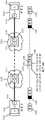
图2图示了本发明一些实施例的受管理的转发节点和控制器集群的示例。Figure 2 illustrates an example of a managed forwarding node and controller cluster of some embodiments of the present invention.
图3图示了在一些实施例中控制器测量处理层产生的测量图的示例。FIG. 3 illustrates an example of a measurement map generated by a controller measurement process layer in some embodiments.
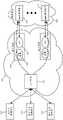
图4A图示了在一些实施例中控制器路径识别层从测量图产生的路由图的示例。4A illustrates an example of a routing graph generated by the controller path identification layer from the measurement graph in some embodiments.
图4B图示了将两个SaaS提供者的已知IP添加到路由图中的数据中心中的最接近这些SaaS提供者的数据中心的两个节点的示例。Figure 4B illustrates an example of adding the known IPs of two SaaS providers to the two nodes in the data centers in the routing graph that are closest to those SaaS providers' data centers.
图4C示出了通过添加两个节点来表示两个SaaS提供者而生成的路由图。Figure 4C shows a routing graph generated by adding two nodes to represent two SaaS providers.
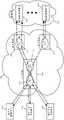
图4D图示了路由图,其中添加了附加节点以表示具有分别连接到两个公共云的已知IP地址的分支机构和数据中心。Figure 4D illustrates a routing graph with additional nodes added to represent branch offices and data centers with known IP addresses connected to the two public clouds, respectively.
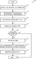
图5图示了控制器路径识别层用来根据从控制器测量层接收到的测量图生成路由图的处理。5 illustrates the process used by the controller path identification layer to generate a routing graph from the measurement graph received from the controller measurement layer.
图6图示了一些实施例的IPsec数据消息格式。Figure 6 illustrates the IPsec data message format of some embodiments.
图7图示了一些实施例的两个封装报头的示例,而图8给出了图示在一些实施例中如何使用这两个报头的示例。Figure 7 illustrates an example of two encapsulation headers for some embodiments, while Figure 8 presents an example illustrating how these two headers are used in some embodiments.
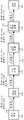
图9-图11图示了当入口、中间和出口MFN接收在两个不同分支机构中的两个计算设备之间发送的消息时分别由入口、中间和出口 MFN执行的消息处置过程。Figures 9-11 illustrate the message handling procedures performed by the ingress, intermediate and egress MFNs, respectively, when messages sent between two computing devices in two different branch offices are received by the ingress, intermediate and egress MFNs.
图12图示了在入口和出口MFN之间不涉及中间MFN的示例。Figure 12 illustrates an example where no intermediate MFN is involved between the ingress and egress MFNs.
图13图示了当入口MFN接收到从分支机构中的公司计算设备发送到另一个分支机构或SaaS提供者数据中心中的另一个设备的消息时,由入口MFN的CFE执行的消息处置处理。13 illustrates the message handling process performed by the CFE of the ingress MFN when the ingress MFN receives a message sent from a corporate computing device in a branch office to another device in another branch office or SaaS provider data center.
图14图示了在出口路由器处执行的NAT操作。Figure 14 illustrates the NAT operation performed at the egress router.
图15图示了由接收从SaaS提供者机器被发送到租户机器的消息的入口路由器执行的消息处置处理。Figure 15 illustrates the message handling process performed by an ingress router that receives messages sent from a SaaS provider machine to a tenant machine.
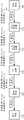
图16图示了被放置在虚拟网络到因特网的出口路径上的每个虚拟网络网关中的此类TM引擎。Figure 16 illustrates such a TM engine placed in each virtual network gateway on the virtual network's egress path to the Internet.
图17图示了在一些实施例中使用的双NAT方法,而不是图16 中示出的单NAT方法。FIG. 17 illustrates the double NAT method used in some embodiments, rather than the single NAT method shown in FIG. 16 .
图18提供了图示入口NAT引擎的源端口翻译的示例。Figure 18 provides an example illustrating source port translation of an ingress NAT engine.
图19图示了SaaS机器响应于其对图18的数据消息的处理而发送的回复消息的处理。FIG. 19 illustrates the processing of a reply message sent by a SaaS machine in response to its processing of the data message of FIG. 18 .
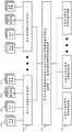
图20给出了示出在一个或多个公共云提供者的N个公共云中具有网络基础设施和(一个或多个)控制器集群的虚拟网络提供者的 M个租户的M个虚拟公司WAN的示例。Figure 20 presents M virtual companies showing M tenants of virtual network providers with network infrastructure and controller cluster(s) in N public clouds of one or more public cloud providers Example of WAN.
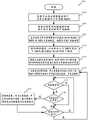
图21概念性地图示了由虚拟网络提供者的控制器集群执行的用于为特定租户部署和管理虚拟WAN的处理。Figure 21 conceptually illustrates the process performed by a virtual network provider's controller cluster to deploy and manage a virtual WAN for a particular tenant.
图22概念性地图示了利用其实现本发明的一些实施例的计算机系统。Figure 22 conceptually illustrates a computer system with which some embodiments of the present invention are implemented.
具体实施方式Detailed ways
在本发明的以下详细描述中,阐述并描述了本发明的许多细节、示例和实施例。但是,对于本领域技术人员而言将显而易见的是,本发明不限于所阐述的实施例,并且可以在不讨论其中一些具体细节和示例的情况下实践本发明。In the following detailed description of the invention, numerous details, examples and embodiments of the invention are set forth and described. However, it will be apparent to those skilled in the art that the invention is not limited to the embodiments set forth and that the invention may be practiced without discussing some of its specific details and examples.
一些实施例在一个或多个区域(例如,若干城市、州、国家等) 中的一个或多个公共云提供者的若干公共云数据中心上为实体建立虚拟网络。可以为其建立这种虚拟网络的实体的示例包括商业实体(例如,公司)、非营利实体(例如,医院、研究机构等)和教育实体(例如,大学、学院等)或任何其它类型的实体。公共云提供者的示例包括Amazon WebServices(AWS)、Google Cloud Platform (GCP)、Microsoft Azure等。Some embodiments establish virtual networks for entities on several public cloud data centers of one or more public cloud providers in one or more regions (eg, several cities, states, countries, etc.). Examples of entities for which such a virtual network may be established include commercial entities (eg, corporations), non-profit entities (eg, hospitals, research institutes, etc.) and educational entities (eg, universities, colleges, etc.) or any other type of entity . Examples of public cloud providers include Amazon Web Services (AWS), Google Cloud Platform (GCP), Microsoft Azure, etc.
一些实施例将虚拟网络定义为跨越若干公共云数据中心(公共云) 以互连私有网络(例如,实体的分支、部、部门或其相关联的数据中心内的网络)、移动用户、SaaS(软件即服务)提供者的机器、 (一个或多个)公共云中的机器和/或服务、以及其它web应用中的一者或多者的覆盖网络。在一些实施例中,高速、可靠的私有网络互连公共云数据中心(公共云)中的两个或更多个。Some embodiments define a virtual network as spanning several public cloud data centers (public clouds) to interconnect private networks (eg, networks within branches, divisions, departments, or their associated data centers of an entity), mobile users, SaaS ( Overlay network of one or more of software as a service) provider's machines, machines and/or services in public cloud(s), and other web applications. In some embodiments, a high-speed, reliable private network interconnects two or more of the public cloud data centers (public clouds).
在一些实施例中,虚拟网络可以被配置为优化实体的数据消息到其目的地的路由,以获得最佳的端到端性能、可靠性和安全性,同时尝试最小化通过因特网的这种流量的路由。而且,在一些实施例中,虚拟网络可以被配置为优化通过网络的数据消息流的层4处理。例如,在一些实施例中,虚拟网络通过跨连接路径拆分速率控制机制来优化 TCP(传输控制协议)连接的端到端速率。In some embodiments, a virtual network may be configured to optimize the routing of an entity's data messages to their destinations for optimal end-to-end performance, reliability, and security, while attempting to minimize such traffic through the Internet route. Also, in some embodiments, the virtual network may be configured to optimize layer 4 processing of data message flow through the network. For example, in some embodiments, the virtual network optimizes the end-to-end rate of TCP (Transmission Control Protocol) connections by splitting rate control mechanisms across connection paths.
一些实施例通过配置在若干公共云中部署的若干部件来建立虚拟网络。在一些实施例中,这些部件包括基于软件的测量代理、软件转发元件(例如,软件路由器、交换机、网关等)、层4连接代理和中间盒服务机器(例如,设备、VM、容器等)。Some embodiments establish a virtual network by configuring several components deployed in several public clouds. In some embodiments, these components include software-based measurement agents, software forwarding elements (eg, software routers, switches, gateways, etc.), layer 4 connectivity agents, and middlebox service machines (eg, devices, VMs, containers, etc.).
一些实施例利用逻辑上集中的控制器集群(例如,一个或多个控制器服务器的集合),其配置公共云部件以在若干公共云上实现虚拟网络。在一些实施例中,这个集群中的控制器位于各种不同的位置 (例如,位于不同的公共云数据中心中),以便改善冗余性和高可用性。当控制器集群中的不同控制器位于不同的公共云数据中心中时,在一些实施例中,控制器共享它们的状态(例如,它们生成以识别租户、通过虚拟网络的路由等的配置数据)。在一些实施例中,控制器集群按比例扩展或收缩用于建立虚拟网络的公共云部件的数量或分配给这些部件的计算或网络资源的数量。Some embodiments utilize a logically centralized controller cluster (eg, a collection of one or more controller servers) that configures public cloud components to implement a virtual network on several public clouds. In some embodiments, the controllers in this cluster are located in various locations (eg, in different public cloud data centers) to improve redundancy and high availability. When different controllers in a controller cluster are located in different public cloud data centers, in some embodiments, the controllers share their state (eg, configuration data they generate to identify tenants, routing through virtual networks, etc.) . In some embodiments, the controller cluster scales up or down the number of public cloud components used to establish the virtual network or the amount of computing or network resources allocated to these components.
一些实施例在相同公共云提供者的相同公共云集合上和/或在相同或不同公共云提供者的不同公共云集合上为不同实体建立不同的虚拟网络。在一些实施例中,虚拟网络提供者提供软件和服务,该软件和服务允许不同的租户在相同或不同的公共云上定义不同的虚拟网络。在一些实施例中,相同的控制器集群或不同的控制器集群可以被用于配置公共云部件,以针对若干不同实体在相同或不同的公共云集合上实现不同的虚拟网络。Some embodiments establish different virtual networks for different entities on the same set of public clouds of the same public cloud provider and/or on different sets of public clouds of the same or different public cloud providers. In some embodiments, the virtual network provider provides software and services that allow different tenants to define different virtual networks on the same or different public clouds. In some embodiments, the same controller cluster or different controller clusters may be used to configure public cloud components to implement different virtual networks on the same or different sets of public clouds for several different entities.
在下面的讨论中提供公司虚拟网络的若干示例。但是,本领域的普通技术人员将认识到的是,一些实施例为其它类型的实体(诸如其它业务实体、非营利组织、教育实体等)定义虚拟网络。而且,如本文档中所使用的,数据消息是指跨网络发送的特定格式的位的集合。本领域普通技术人员将认识到的是,术语“数据消息”在本文档中用于指代跨网络发送的各种格式的位的集合。这些位的格式可以由标准化协议或非标准化协议指定。遵循标准化协议的数据消息的示例包括以太网帧、IP分组、TCP片段、UDP数据报等。而且,如本文档中所使用的,对L2、L3、L4和L7层(或层2、层3、层4或层7)的引用分别是对OSI(开放系统互连)层模型的第二数据链路层、第三网络层、第四传输层和第七应用层的引用。Several examples of corporate virtual networks are provided in the discussion below. However, those of ordinary skill in the art will recognize that some embodiments define virtual networks for other types of entities, such as other business entities, nonprofit organizations, educational entities, and the like. Also, as used in this document, a data message refers to a collection of bits in a particular format sent across a network. One of ordinary skill in the art will recognize that the term "data message" is used in this document to refer to a collection of bits in various formats sent across a network. The format of these bits can be specified by a standardized protocol or a non-standardized protocol. Examples of data messages that follow standardized protocols include Ethernet frames, IP packets, TCP fragments, UDP datagrams, and the like. Also, as used in this document, references to L2, L3, L4, and L7 layers (or Layer 2, Layer 3, Layer 4, or Layer 7), respectively, are the second reference to the OSI (Open Systems Interconnection) layer model References to the data link layer, the third network layer, the fourth transport layer, and the seventh application layer.
图1A给出了虚拟网络100,该虚拟网络100是在两个公共云提供者A和B的若干公共云数据中心105和110上为公司定义的。如图所示,虚拟网络100是安全的覆盖网络,通过在不同的公共云中部署不同的受管理的转发节点150并通过覆盖隧道152将受管理的转发节点(MFN)彼此连接来建立。在一些实施例中,MFN是公共云数据中心中的若干不同部件的概念性分组,其与其它公共云数据中心中的其它MFN(与部件的其它组)一起为一个或多个实体建立一个或多个覆盖虚拟网络。Figure 1A presents a
如以下进一步描述的,在一些实施例中,形成MFN的部件的组包括(1)一个或多个VPN网关,用于与作为公共云数据中心之外的外部机器位置的实体的计算节点(例如,办公室、私有数据中心、远程用户等)建立VPN连接,(2)一个或多个转发元件,用于在彼此之间转发封装后的数据消息,以便在共享的公共云网络架构上定义覆盖虚拟网络,(3)一个或多个服务机器,用于执行中间盒服务操作以及L4-L7优化,以及(4)一个或多个测量代理,用于获得关于公共云数据中心之间的网络连接质量的测量,以便识别通过公共云数据中心的期望路径。在一些实施例中,出于冗余和可扩展性的原因,不同的MFN可以具有不同的布置和不同数量的此类部件,并且一个 MFN可以具有不同数量的此类部件。As described further below, in some embodiments, the set of components that form the MFN includes (1) one or more VPN gateways for communicating with a compute node (eg, an entity that is an external machine location outside of a public cloud data center) , offices, private data centers, remote users, etc.) to establish VPN connections, (2) one or more forwarding elements for forwarding encapsulated data messages between each other to define overlay virtual network, (3) one or more service machines for performing middlebox service operations and L4-L7 optimization, and (4) one or more measurement agents for obtaining information about the quality of network connections between public cloud data centers measurements in order to identify the desired path through the public cloud data center. In some embodiments, different MFNs may have different arrangements and different numbers of such components, and one MFN may have different numbers of such components, for redundancy and scalability reasons.
而且,在一些实施例中,每个MFN的部件组在MFN的公共云数据中心中的不同计算机上执行。在一些实施例中,MFN的若干或全部部件可以在公共云数据中心的一个计算机上执行。在一些实施例中,MFN的部件在还执行其它租户的其它机器的主机上执行。这些其它机器可以是其它租户的其它MFN的其它机器,或者可以是其它租户的不相关的机器(例如,计算VM或容器)。Also, in some embodiments, the component sets of each MFN execute on different computers in the MFN's public cloud data center. In some embodiments, several or all components of MFN may execute on one computer in a public cloud data center. In some embodiments, components of the MFN execute on hosts of other machines that also execute other tenants. These other machines may be other machines of other MFNs of other tenants, or may be unrelated machines of other tenants (eg, compute VMs or containers).
在一些实施例中,虚拟网络100由虚拟网络提供者(VNP)部署,该虚拟网络提供者在相同或不同的公共云数据中心上针对不同实体 (例如,虚拟网络提供者的不同公司客户/租户)部署不同的虚拟网络。在一些实施例中,虚拟网络提供者是部署MFN并提供用于配置和管理这些MFN的控制器集群的实体。In some embodiments, the
虚拟网络100将公司计算端点(诸如数据中心、分支机构和移动用户)彼此连接,并连接到驻留在公共云中或驻留在可通过因特网访问的私有数据中心中的外部服务(例如,公共web服务,或SaaS服务,诸如Office365或Salesforce)。这种虚拟网络充分利用不同公共云的不同位置将不同的公司计算端点(例如,公司的不同私有网络和/或不同移动用户)连接到它们附近的公共云。在下面的讨论中,公司计算端点也称为公司计算节点。
在一些实施例中,虚拟网络100还充分利用将这些公共云互连的高速网络以通过公共云将数据消息转发到它们的目的地或尽可能接近它们的目的地,同时减少它们遍历通过因特网。当公司计算端点在虚拟网络所跨越的公共云数据中心之外时,这些端点被称为外部机器位置。公司分支机构、私有数据中心和远程用户的设备就是这种情况。In some embodiments,
在图1A所示的示例中,虚拟网络100跨越公共云提供者A的六个数据中心105a-105f和公共云提供者B的四个数据中心110a-110d。在跨越这些公共云时,这种虚拟网络连接位于不同地理区域中的公司租户的分支机构、公司数据中心、SaaS提供者和移动用户中的若干个。具体而言,虚拟网络100连接两个不同城市(例如,加利福尼亚州的旧金山和印度的浦那)中的两个分支机构130a和130b、另一个城市(例如,华盛顿州的西雅图)中的公司数据中心134、在另外两个城市(华盛顿的雷德蒙德和法国的巴黎)中的两个SaaS提供者数据中心136a和136b,以及世界各地的移动用户140。照此,这种虚拟网络可以被视为虚拟公司WAN。In the example shown in FIG. 1A, the
在一些实施例中,分支机构130a和130b具有其自己的私有网络 (例如,局域网),该私有网络连接分支位置处的计算机和公共云之外的分支私有数据中心。类似地,在一些实施例中,公司数据中心 134具有其自己的私有网络并且驻留在任何公共云数据中心之外。但是,在其它实施例中,公司数据中心134或分支130a和130b的数据中心可以在公共云内,但是虚拟网络不跨越这个公共云,因为公司或分支数据中心连接到虚拟网络100的边缘。In some embodiments,
如上面所提到的,通过经由覆盖隧道152连接不同公共云中不同的部署的受管理的转发节点150来建立虚拟网络100。每个受管理的转发节点150包括若干可配置的部件。如上面进一步描述和下面进一步描述的,在一些实施例中,MFN部件包括基于软件的测量代理、软件转发元件(例如,软件路由器、交换机、网关等)、层4代理 (例如,TCP代理)和中间盒服务机器(例如,VM、容器等)。在一些实施例中,这些部件中的一个或多个使用标准化或通常可用的方案,诸如Open vSwitch、OpenVPN、strongSwan等。As mentioned above, the
在一些实施例中,每个MFN(即,概念性地形成MFN的部件的组)可以由在公共云数据中心中部署和配置MFN的虚拟网络提供者的不同租户共享。结合地或可替代地,在一些实施例中,虚拟网络提供者可以在一个或多个公共云数据中心中为特定租户部署唯一的 MFN集合。例如,出于安全性原因或服务质量原因,特定租户可能不希望与另一个租户共享MFN资源。对于这样的租户,虚拟网络提供者可以跨若干公共云数据中心部署其自己的MFN集合。In some embodiments, each MFN (ie, the group of components that conceptually form the MFN) may be shared by different tenants of the virtual network provider that deploys and configures the MFN in a public cloud data center. In combination or alternatively, in some embodiments, a virtual network provider may deploy a unique set of MFNs for a particular tenant in one or more public cloud data centers. For example, a particular tenant may not wish to share MFN resources with another tenant for security reasons or quality of service reasons. For such tenants, the virtual network provider may deploy its own set of MFNs across several public cloud data centers.
在一些实施例中,逻辑上集中的控制器集群160(例如,一个或多个控制器服务器的集合)在公共云105和110中的一个或多个的内部或外部操作,并配置受管理的转发节点150的公共云部件,以在公共云105和110上实现虚拟网络。在一些实施例中,这个集群中的控制器位于各种不同的位置(例如,位于不同的公共云数据中心中),以便改善冗余性和高可用性。在一些实施例中,控制器集群按比例扩展或收缩用于建立虚拟网络的公共云部件的数量或分配给这些部件的计算或网络资源的数量。In some embodiments, a logically centralized controller cluster 160 (eg, a collection of one or more controller servers) operates internally or externally to one or more of the
在一些实施例中,控制器集群160或虚拟网络提供者的另一个控制器集群在相同的公共云105和110上和/或在不同公共云提供者的不同公共云上为另一个公司租户建立不同的虚拟网络。除了(一个或多个)控制器集群之外,在其它实施例中,虚拟网络提供者还在公共云中部署转发元件和服务机器,这允许不同租户在相同或不同的公共云上部署不同的虚拟网络。图1B图示了用于在公共云105和110上部署的两个公司租户的两个虚拟网络100和180的示例。图1C可替代地图示了两个虚拟网络100和182的示例,其中一个网络100部署在公共云105和110上,而另一个虚拟网络182部署在另一对公共云 110和115上。In some embodiments, the
通过MFN的经配置的部件,图1A的虚拟网络100允许公司租户的不同私有网络和/或不同移动用户连接到相对于这些私有网络和/ 或移动用户而言处于最优位置(例如,如在物理距离方面,在连接速度、损失、延迟和/或成本方面,和/或在网络连接可靠性方面等等所测量的)的不同公共云。在一些实施例中,这些部件还允许虚拟网络 100使用互连公共云的高速网络,以通过公共云将数据消息转发到其目的地,同时减少它们遍历通过因特网。Through the configured components of the MFN, the
在一些实施例中,MFN部件还被配置为在网络层、传输层和应用层运行新颖的处理,以优化端到端的性能、可靠性和安全性。在一些实施例中,这些处理中的一个或多个实现专有的高性能联网协议,而没有当前的网络协议僵化。照此,在一些实施例中,虚拟网络100 不受因特网自治系统、路由协议或者甚至端到端传输机制的限制。In some embodiments, the MFN components are also configured to run novel processing at the network layer, transport layer, and application layer to optimize end-to-end performance, reliability, and security. In some embodiments, one or more of these processes implement a proprietary high-performance networking protocol without the rigidity of current networking protocols. As such, in some embodiments,
例如,在一些实施例中,MFN 150的部件(1)创建优化的多路径和自适应集中式路由,(2)提供强大的QoS(服务质量)保证,(3)优化通过中间TCP拆分和/或终止的端到端TCP速率,以及 (4)将可扩展的应用级中间盒服务(例如,防火墙、入侵检测系统 (IDS)、入侵防御系统(IPS)、WAN优化等)重新定位到全局网络功能虚拟化(NFV)中云的计算部分。因而,可以优化虚拟网络以适应公司的定制的且不断变化的需求,而不必绑定到现有的网络协议。而且,在一些实施例中,虚拟网络可以被配置为“随用随付”的基础设施,其可以根据连续的要求改变而动态且弹性地在性能能力和地理范围两者上进行扩展和收缩。For example, in some embodiments, components of MFN 150 (1) create optimized multipath and adaptive centralized routing, (2) provide strong QoS (Quality of Service) guarantees, (3) optimize through intermediate TCP splitting and End-to-end TCP rates for termination, and (4) relocation of scalable application-level middlebox services (eg, firewalls, intrusion detection systems (IDS), intrusion prevention systems (IPS), WAN optimization, etc.) to the global The computing part of the cloud in Network Functions Virtualization (NFV). Thus, virtual networks can be optimized to fit a company's customized and changing needs without necessarily being tied to existing network protocols. Also, in some embodiments, a virtual network may be configured as a "pay as you go" infrastructure that can dynamically and elastically expand and contract in both performance capabilities and geographic scope in response to continuous demand changes.
为了实现虚拟网络100,虚拟网络所跨越的每个公共云数据中心 105a-105f和110a-110d中的至少一个受管理的转发节点150必须由控制器集合来配置。图2图示了本发明一些实施例的受管理的转发节点150和控制器集群160的示例。在一些实施例中,每个受管理的转发节点150是在公共云数据中心中的主机计算机上执行的机器(例如, VM或容器)。在其它实施例中,每个受管理的转发节点150由在一个公共云数据中心中的相同主机计算机上执行的多个机器(例如,多个VM或容器)实现。在还有其它实施例中,一个MFN的两个或更多个部件可以由在一个或多个公共云数据中心中的两个或更多个主机计算机上执行的两个或更多个机器来实现。To implement
如图所示,受管理的转发节点150包括测量代理205、防火墙和 NAT中间盒服务引擎210和215、一个或多个优化引擎220、边缘网关225和230以及云转发元件235(例如,云路由器)。在一些实施例中,这些部件205-235中的每一个可以被实现为两个或更多个部件的集群。As shown, managed forwarding
在一些实施例中,控制器集群160可以动态地按比例扩展或收缩每个部件集群(1)以添加或移除机器(例如,VM或容器)以实现每个部件的功能,和/或(2)以向实现那个集群的部件的先前部署的计算机添加或移除计算和/或网络资源。照此,公共云数据中心中的每个部署的MFN 150可以被视为MFN的集群,或者它可以被视为包括执行MFN的不同操作的多个不同部件集群的节点。In some embodiments, the
而且,在一些实施例中,控制器集群在公共云数据中心中为不同的租户部署MFN的不同集合,控制器集群在公共云数据中心上为租户定义了虚拟网络。在这种方法中,任何两个租户的虚拟网络都不共享任何MFN。但是,在下面描述的实施例中,每个MFN可以被用于为不同的租户实现不同的虚拟网络。普通技术人员将认识到的是,在其它实施例中,控制器集群160可以利用其自己的部署的MFN的专用集合来实现第一租户集合中的每个租户的虚拟网络,同时利用部署的MFN的共享集合来实现第二租户集合中的每个租户的虚拟网络。Also, in some embodiments, the controller cluster deploys different sets of MFNs for different tenants in the public cloud data center, and the controller cluster defines virtual networks for the tenants on the public cloud data center. In this approach, no MFN is shared by any two tenants' virtual networks. However, in the embodiments described below, each MFN may be used to implement different virtual networks for different tenants. Those of ordinary skill will appreciate that in other embodiments, the
在一些实施例中,分支网关225和远程设备网关230分别与连接到MFN 150的一个或多个分支机构130和远程设备(例如,移动设备140)建立安全的VPN连接,如图2中所示。这种VPN连接的一个示例是IPsec连接,下面将对其进行进一步描述。但是,本领域普通技术人员将认识到的是,在其它实施例中,此类网关225和/或230 建立不同类型的VPN连接。In some embodiments,
在一些实施例中,MFN 150包括执行一个或多个中间盒服务操作(诸如防火墙操作、NAT操作、IPS操作、IDS操作、负载均衡操作、WAN优化操作等)的一个或多个中间盒引擎。通过在公共云中部署的MFN中结合这些中间盒操作(例如,防火墙操作、WAN优化操作等)中,虚拟网络100在公共云中实现传统上由公司的(一个或多个)数据中心和/或(一个或多个)分支机构处的公司WAN基础设施执行的许多功能。In some embodiments,
因而,对于许多中间盒服务,公司计算节点(例如,远程设备、分支机构和数据中心)不再必须访问私有数据中心或分支机构中公司的WAN基础设施,因为这些服务中的许多现在已部署在公共云中。这种方法加快了公司计算节点(例如,远程设备、分支机构和数据中心)对这些服务的访问,并避免了私有数据中心处原本专用于提供此类服务的昂贵的拥塞网络瓶颈。Thus, for many middlebox services, corporate computing nodes (eg, remote devices, branch offices, and data centers) no longer have to access private data centers or the company's WAN infrastructure in branch offices, since many of these services are now deployed in in the public cloud. This approach speeds up access to these services from corporate computing nodes (eg, remote devices, branch offices, and data centers) and avoids costly congested network bottlenecks at private data centers that would otherwise be dedicated to providing such services.
这种方法有效地将WAN网关功能分发到公共云数据中心中的各种MFN。例如,在一些实施例的虚拟网络100中,大多数或全部传统公司WAN网关安全功能(例如,防火墙操作、入侵检测操作、入侵防御操作等)被移动到公共云MFN(例如,将来自计算端点的数据接收到虚拟网络中的入口MFN)。这有效地允许虚拟网络100具有在实现虚拟网络100的许多不同的MFN处实现的分布式WAN网关。This approach effectively distributes WAN gateway functions to various MFNs in public cloud data centers. For example, in the
在图2所示的示例中,MFN 150被示为包括防火墙引擎210、 NAT引擎215和一个或多个L4-L7优化引擎。普通技术人员将意识到的是,在其它实施例中,MFN 150包括用于执行其它中间盒操作的其它中间盒引擎。在一些实施例中,防火墙引擎210对以下强制实施防火墙规则:(1)其进入虚拟网络的入口路径上的数据消息流 (例如,对网关225和230从分支机构130和移动设备140接收并处理的数据消息流)以及(2)其离开虚拟网络的出口路径上的数据消息流(例如,对通过NAT引擎215和因特网202发送到SaaS提供者数据中心的数据消息流)。In the example shown in FIG. 2,
在一些实施例中,当防火墙引擎属于这样的MFN时,该MFN 是数据消息流进入虚拟网络的入口MFN与数据消息流离开虚拟网络的出口MFN之间的中间跳,MFN 150的防火墙引擎210也强制实施防火墙规则。在其它实施例中,防火墙引擎210仅在它是数据消息流的入口MFN和/或出口MFN的一部分时才强制实施防火墙规则。In some embodiments, when the firewall engine belongs to an MFN that is an intermediate hop between the ingress MFN where data message flows enter the virtual network and the egress MFN where data message flows leave the virtual network,
在一些实施例中,NAT引擎215执行网络地址翻译,以在数据消息流离开虚拟网络通过因特网202到达第三方设备(例如,改变为 SaaS提供者机器)的出口路径上改变数据消息流的源网络地址。此类网络地址翻译确保可以将第三方机器(例如,SaaS机器)正确地配置为处理数据消息流,如果没有地址翻译,则可能会指定租户和/ 或公共云提供者的私有网络地址。由于不同租户和/或云提供者的私有网络地址可能重叠,因此这尤其成问题。地址翻译还确保来自第三方设备(例如,SaaS机器)的回复消息可以被虚拟网络(例如,被消息从其离开虚拟网络的MFN NAT引擎)正确接收。In some embodiments, the
在一些实施例中,MFN的NAT引擎215对离开虚拟网络到达第三方机器或从第三方机器进入虚拟网络的每个数据消息流执行双 NAT操作。如下面进一步描述的,两个NAT操作中的一个NAT操作在数据消息流进入虚拟网络时对其入口MFN处的这种数据消息流执行,而另一个NAT操作在数据消息流离开虚拟网络时对其出口 MFN处的数据消息流执行。In some embodiments, the MFN's
这种双NAT方法允许将更多租户私有网络映射到公共云提供者的网络。这种方法还减轻了用于将关于改变租户私有网络的数据分发给MFN的负担。在入口或出口NAT操作之前,一些实施例执行租户映射操作,该操作使用租户标识符首先将租户的源网络地址映射到另一个源网络地址,然后通过NAT操作将其映射到再另一个源网络地址。执行双NAT操作减轻了用于将关于改变租户私有网络的数据进行分发的数据分发负担。This double NAT approach allows more tenant private networks to be mapped to the public cloud provider's network. This approach also relieves the burden of distributing data to the MFN regarding changes to the tenant's private network. Before an ingress or egress NAT operation, some embodiments perform a tenant mapping operation that uses the tenant identifier to first map the tenant's source network address to another source network address, and then map it to yet another source network through the NAT operation address. Performing a double NAT operation relieves the data distribution burden for distributing data on changing tenant private networks.
优化引擎220执行新颖的处理,该处理优化实体的数据消息到其目的地的转发,以实现最佳的端到端性能和可靠性。其中一些处理实现专有的高性能联网协议,而没有当前的网络协议僵化。例如,在一些实施例中,优化引擎220通过中间TCP拆分和/或终止来优化端到端TCP速率。The
云转发元件235是这样的MFN引擎,当数据消息流必须对另一个公共云进行遍历以到达其目的地时,其负责将数据消息流转发到下一跳MFN的云转发元件(CFE),或者当数据消息流可以通过相同公共云到达其目的地时,其负责将数据消息流转发到相同公共云中的出口路由器。在一些实施例中,MFN 150的CFE 235是软件路由器。
为了转发数据消息,CFE用隧道报头封装消息。不同的实施例使用不同的方法来用隧道报头封装数据消息。当数据消息必须遍历一个或多个中间MFN以到达出口MFN时,以下描述的一些实施例使用一个隧道报头来识别用于进入和离开虚拟网络的网络入口/出口地址,并使用另一个隧道报头来识别下一跳MFN。To forward data messages, the CFE encapsulates the message with a tunnel header. Different embodiments use different methods to encapsulate data messages with tunnel headers. When a data message must traverse one or more intermediate MFNs to reach an egress MFN, some embodiments described below use one tunnel header to identify the network ingress/egress addresses for entering and leaving the virtual network, and another tunnel header to Identify the next-hop MFN.
具体而言,在一些实施例中,CFE发送具有两个隧道报头的数据消息:(1)识别进入和离开虚拟网络的入口CFE和出口CFE的内部报头,以及(2)识别下一跳CFE的外部报头。在一些实施例中,内部隧道报头还包括租户标识符(TID),以便允许虚拟网络提供者的多个不同租户使用虚拟网络提供者的常见的MFN CFE集合。其它实施例以不同方式定义隧道报头,以便定义覆盖虚拟网络。Specifically, in some embodiments, the CFE sends a data message with two tunnel headers: (1) an inner header identifying the ingress CFE and egress CFE entering and leaving the virtual network, and (2) an inner header identifying the next-hop CFE outer header. In some embodiments, the inner tunnel header also includes a tenant identifier (TID) to allow multiple different tenants of the virtual network provider to use the virtual network provider's common set of MFN CFEs. Other embodiments define tunnel headers differently in order to define overlay virtual networks.
为了在一个或多个公共云上为租户部署虚拟网络,控制器集群 (1)基于租户的公司计算节点(例如,分支机构、数据中心、移动用户和SaaS提供者)的位置来识别用于进入和离开租户的虚拟网络的可能入口和出口路由器,以及(2)识别通过实现虚拟网络的其它中间公共云路由器从识别出的入口路由器遍历到识别出的出口路由器的路由。在识别出这些路由之后,控制器集群将这些路由传播到(一个或多个)公共云中的MFN CFE 235的转发表。在使用基于OVS 的虚拟网络路由器的实施例中,控制器通过使用OpenFlow来分发路由。To deploy a virtual network for a tenant on one or more public clouds, the controller cluster (1) identifies the location for the tenant based on the location of the tenant's corporate computing nodes (eg, branch offices, data centers, mobile users, and SaaS providers). and possible ingress and egress routers from the tenant's virtual network, and (2) identify routes to traverse from the identified ingress router to the identified egress router through other intermediate public cloud routers implementing the virtual network. After identifying these routes, the controller cluster propagates these routes to the forwarding table of the
在一些实施例中,控制器集群160还可以配置实现虚拟网络以优化若干网络处理层的每个MFN 150的部件205-235,以便获得最佳的端到端性能、可靠性和安全性。例如,在一些实施例中,这些部件被配置为(1)优化层3流量路由(例如,最短路径、分组重复), (2)优化层4TCP拥塞控制(例如,分段、速率控制),(3)实现安全性特征(例如,加密、深度分组检查、防火墙),以及(4) 实现应用层压缩特征(例如,重复数据删除、高速缓存)。在虚拟网络内,对公司流量进行安全保护、检查和日志记录。In some embodiments, the
在一些实施例中,为公共云数据中心中的每个MFN部署一个测量代理。在其它实施例中,公共云数据中心或数据中心的集合中(例如,附近相关联的数据中心(诸如一个可用区中的数据中心)的集合中)的多个MFN共享一个测量代理。为了优化层3和层4处理,与每个受管理的转发节点150相关联的测量代理205重复生成测量值,该测量值量化其节点与每个若干其它“相邻”节点之间的网络连接的质量。In some embodiments, one measurement agent is deployed for each MFN in the public cloud data center. In other embodiments, multiple MFNs in a public cloud data center or collection of data centers (eg, in a collection of nearby associated data centers (such as data centers in an Availability Zone)) share a single measurement agent. To optimize layer 3 and layer 4 processing, the
不同的实施例以不同方式定义相邻节点。对于特定公共云提供者的一个公共云数据中心中的特定MFN,在一些实施例中,相邻节点包括(1)在特定公共云提供者的任何公共云数据中心中操作的任何其它MFN,以及(2)在与特定MFN处于相同“区域”内的另一个公共云提供者的数据中心中操作的任何其它MFN。Different embodiments define adjacent nodes in different ways. For a particular MFN in one public cloud data center of a particular public cloud provider, in some embodiments, the adjacent nodes include (1) any other MFN operating in any public cloud data center of the particular public cloud provider, and (2) Any other MFN operating in another public cloud provider's data center within the same "region" as the particular MFN.
不同的实施例以不同方式定义相同区域。例如,一些实施例按照距离来定义区域,该距离指定围绕特定受管理的转发节点的边界形状。其它实施例按照城市、州或地区来定义区域,诸如北加利福尼亚、南加利福尼亚等。这种方法的假设是,相同公共云提供者的不同数据中心以非常高速度网络连接被连接,而不同公共云提供者的数据中心之间的网络连接在数据中心位于相同区域内时可能快,而当数据中心位于不同区域中时可能不那么快。当数据中心位于不同区域中时,不同公共云提供者的数据中心之间的连接可能必须遍历公共因特网很长距离。Different embodiments define the same region in different ways. For example, some embodiments define regions in terms of distances that specify the shape of the boundaries around a particular managed forwarding node. Other embodiments define regions by city, state, or region, such as Northern California, Southern California, and the like. The assumption of this approach is that different data centers of the same public cloud provider are connected with very high speed network connections, while network connections between data centers of different public cloud providers may be fast when the data centers are located in the same region, And maybe not so fast when the data centers are in different regions. When data centers are located in different regions, connections between data centers of different public cloud providers may have to traverse long distances over the public Internet.
在不同的实施例中,测量代理205以不同方式生成测量值。在一些实施例中,测量代理周期性地(例如,每秒、每N秒、每分钟、每M分钟等一次)向其相邻的受管理的转发节点的每个测量代理发送ping消息(例如,UDP回声消息)。鉴于ping消息的小尺寸,它们不会导致大的网络连接费用。例如,对于100个节点,每个节点每10秒向每个其它节点发送一次ping,那么对于每个节点生成大约 10kb/s的入口和出口测量流量,并且鉴于当前的公共云价格,这将导致每个节点每年几美元的网络消费费用(例如,5美元)。In different embodiments,
基于其接收到的回复消息的速度,测量代理205计算并更新测量度量值(诸如网络连接吞吐速度、延迟、损失和链路可靠性)。通过重复进行这些操作,测量代理205定义并更新测量结果矩阵,该矩阵表述与其相邻节点的网络连接的质量。当代理205与其相邻节点的测量代理交互时,其测量矩阵仅量化与其本地节点团(clique)的连接的质量。Based on the speed at which it receives reply messages, the
不同的受管理的转发节点的测量代理将其测量矩阵发送到控制器集群160,该控制器集群然后聚合所有不同的团连接数据以获得不同对的受管理的转发节点之间的连接的聚合网格视图。当控制器集群 160为两对转发节点之间的链路收集不同的测量(例如,由一个节点在不同时间进行的测量)时,控制器集群根据不同的测量产生混合的值(例如,产生测量的平均值或加权平均值)。在一些实施例中,聚合网格视图是每对受管理的转发节点之间的所有网络连接的全网格视图,而在其它实施例中,它是比由各个受管理的转发节点的测量代理产生的视图更完整的视图。The measurement agents of the different managed forwarding nodes send their measurement matrices to the
如图2中所示,控制器集群160包括一个或多个测量处理引擎 280、一个或多个路径识别引擎282和一个或多个管理接口284的集群。为了避免用不必要的细节模糊本描述,下面将按照单个引擎或接口层(即,按照测量处理层280、路径识别层282和管理接口层284)提到这些集群中的每一个。As shown in FIG. 2, the
测量处理层280从受管理的转发节点的测量代理205接收测量矩阵,并处理这些测量矩阵以产生表述不同对的受管理的转发节点之间的连接质量的聚合网格矩阵。测量处理层280将聚合网格矩阵提供给路径识别层282。基于聚合网格矩阵,路径识别层282识别用于连接不同公司数据端点(例如,不同分支机构、公司数据中心、SaaS提供者数据中心和/或远程设备)的通过虚拟网络的不同期望路由路径。然后,这个层282在路由表中提供这些路由路径,路由表被分发给受受管理的转发节点150的云转发元件235。The
在一些实施例中,针对每对数据消息端点的识别出的路由路径是基于优化准则集合被认为最优的路由路径,例如,它是最快的路由路径、最短的路由路径或使用因特网最少的路径。在其它实施例中,路径识别引擎可以在相同的两个端点之间识别并提供(在路由表中)多个不同的路由路径。在这些实施例中,受管理的转发节点150的云转发元件235然后基于它们正在强制实施的QoS准则或其它运行时准则来选择路径之一。在一些实施例中,每个CFE 235不接收从CFE 到虚拟网络的出口点的整个路由路径,而是接收该路径的下一跳。In some embodiments, the identified routing path for each pair of data message endpoints is the routing path deemed optimal based on a set of optimization criteria, eg, it is the fastest routing path, the shortest routing path, or the least Internet-using route path. In other embodiments, the path identification engine may identify and provide (in the routing table) multiple distinct routing paths between the same two endpoints. In these embodiments, the
在一些实施例中,路径识别层282使用聚合网格矩阵中的测量值作为其执行以构造全局路由图的路由算法的输入。在一些实施例中,这个全局路由图是测量处理层280产生的测量图的聚合和优化版本。图3图示了在一些实施例中控制器测量处理层280产生的测量图300 的示例。这个图描绘了AWS和GCP公共云310和320中(即, AWS和GCP的数据中心中)各种受管理的转发节点150之间的网络连接。图4A图示了在一些实施例中控制器路径识别层282根据测量图300产生的路由图400的示例。In some embodiments, the
图5图示了控制器路径识别层用来根据从控制器测量层接收到的测量图生成路由图的处理500。当路径识别层282从控制器测量层重复接收到更新后的测量图时,路径识别层282重复执行这个处理500 (例如,每次接收到新测量图时或每第N次接收到新测量图时执行处理500)。在其它实施例中,路径识别层282周期性地执行这个处理(例如,每12小时或24小时一次)。5 illustrates a
如图所示,路径识别层最初将路由图定义(在505处)为与测量图完全相同(即,在相同对的受管理的转发节点之间具有相同的链路)。在510处,该处理从测量图300中移除坏链路。坏链路的示例包括消息丢失过多或可靠性差的链路(例如,最近15分钟内消息丢失大于2%的链路,或最近2分钟内消息丢失大于10%的链路)。图 4A图示了在路由图400中排除了测量图300中的链路302、304和 306。这个图通过用虚线描绘这些链路来图示这些链路的排除。As shown, the path identification layer initially defines (at 505) the routing graph to be identical to the measurement graph (ie, having the same links between the same pair of managed forwarding nodes). At 510 , the process removes bad links from
接下来,在515处,处理500将链路权重得分(成本得分)计算为若干计算出的且特定于提供者的值的加权组合。在一些实施例中,权重得分是链路的以下内容的加权组合:(1)计算出的延迟值、(2) 计算出的损失值、(3)提供者网络连接成本和(4)提供者计算成本。在一些实施例中,由于通过链路连接的受管理的转发节点是在(一个或多个)公共云数据中心中的主机计算机上执行的机器(例如,VM 或容器),因此考虑了提供者的计算成本。Next, at 515, the
在520处,该处理将用于虚拟网络中的数据消息流的已知源IP 地址和目的地IP地址(例如,由公司实体使用的SaaS提供者的已知IP)添加到路由图。在一些实施例中,该处理将可能的消息流端点的每个已知IP地址添加到路由图中最接近那个端点的节点(例如,添加到表示MFN的节点)。在这样做时,在一些实施例中,该处理假设每个这样的端点通过具有零延迟成本和零损失成本的链路连接到虚拟网络。图4B图示了将两个SaaS提供者的已知IP添加到路由图中的两个节点402和404(表示两个MFN)的示例,该两个节点在数据中心中最靠近这些SaaS提供者的数据中心。在这个示例中,一个节点在AWS公共云中,而另一个节点在GCP公共云中。At 520, the process adds known source IP addresses and destination IP addresses for data message flows in the virtual network (eg, known IPs of SaaS providers used by corporate entities) to the routing map. In some embodiments, the process adds each known IP address of a possible message flow endpoint to the node in the routing graph closest to that endpoint (eg, to the node representing the MFN). In doing so, in some embodiments, the process assumes that each such endpoint is connected to the virtual network by a link with zero latency cost and zero loss cost. Figure 4B illustrates an example of adding the known IPs of two SaaS providers to two
可替代地或相结合地,在一些实施例中,通过将节点添加到这个图中以表示源端点和目的地端点、将IP地址指派给这些节点并将权重值指派给将这些添加的节点连接到路由图中的其它节点(例如,连接到路由图中表示公共云中的MFN的节点),处理500将已知的源 IP地址和目的地IP地址添加到路由图。当流的源端点和目的地端点被添加为节点时,路径识别引擎282可以在识别出通过不同源端点和目的地端点之间的虚拟网络的不同路由时考虑到达这些节点的成本 (例如,距离成本、延迟成本和/或财务成本等)。Alternatively or in combination, in some embodiments, these added nodes are connected by adding nodes to this graph to represent source and destination endpoints, assigning IP addresses to these nodes, and assigning weight values to the nodes. To other nodes in the routing graph (eg, nodes connected to the routing graph representing MFNs in the public cloud),
图4C图示了通过将两个节点412和414添加到图4A的节点图 400以便表示两个SaaS提供者而生成的路由图410。在这个示例中,已知的IP地址被指派给节点412和414,并且这些节点通过链路416 和418连接到节点402和404(表示两个MFN),链路416和418 被指派了权重W1和W2。这种方法是用于将两个SaaS提供者的已知IP地址添加到图4B中所示方法的替代方法。Figure 4C illustrates a
图4D图示了更详细的路由图415。在这个更详细的路由图中,添加了附加节点422和424,以表示分别连接到AWS和GCP公共云310和320的具有已知IP地址的外部公司计算节点(例如,分支机构和数据中心)。这些节点422/424中的每一个通过具有相关联的权重值Wi的至少一个链路426连接到路由图节点中的表示MFN的至少一个路由图节点。这些节点中的一些(例如,分支机构中的一些) 通过多条链路连接到相同MFN或不同MFN。FIG. 4D illustrates a more detailed routing diagram 415 . In this more detailed routing graph,
接下来,在525处,处理500计算每个MFN与可以用作公司实体的数据消息流的虚拟网络出口位置的每个其它MFN之间的最低成本路径(例如,最短路径等)。在一些实施例中,出口MFN包括连接到外部公司计算节点(例如,分支机构、公司数据中心和SaaS提供者数据中心)的MFN,以及作为移动设备连接和出口因特网连接的候选位置的MFN。在一些实施例中,这种计算使用传统的最低成本(例如,最短路径)识别处理,该处理识别不同MFN对之间的最短路径。Next, at 525, the
对于每个候选MFN对,当在MFN对之间存在多条这样的路径时,最低成本识别处理使用计算出的权重得分(即,在510处计算出的得分)来识别具有最低得分的路径。下面将进一步描述用于计算最低成本路径的若干方式。如上面所提到的,在一些实施例中,路径识别层282识别两个MFN对之间的多条路径。这是为了允许云转发元件235在不同情况下使用不同路径。因而,在这些实施例中,处理 500可以识别两个MFN对之间的多条路径。For each candidate MFN pair, when there are multiple such paths between the MFN pairs, the lowest cost identification process uses the calculated weight score (ie, the score calculated at 510) to identify the path with the lowest score. Several ways for calculating the least cost path are described further below. As mentioned above, in some embodiments, the
在530处,该处理从路由图中移除在525处识别出的任何最低成本路径都未使用的MFN对之间的链路。接下来,在535处,该处理根据路由图生成用于云转发元件235的路由表。在535处,该处理将这些路由表分发给受管理的转发节点的云转发元件235。在535之后,该处理结束。At 530, the process removes from the routing graph links between pairs of MFNs that are not used by any of the lowest cost paths identified at 525. Next, at 535, the process generates a routing table for
在一些实施例中,虚拟网络具有两种类型的外部连接,它们是:In some embodiments, the virtual network has two types of external connections, which are:
(1)与实体的计算节点(例如,分支机构、数据中心、移动用户等) 的外部安全连接,以及(2)通过因特网到第三方计算机(例如, SaaS提供者服务器)的外部连接。一些实施例通过为终止于虚拟网络之外的源节点和目的地节点处的每条数据路径找到最优虚拟网络入口和出口位置来优化虚拟网络。例如,为了将分支机构连接到SaaS 提供者服务器(例如,salesforce.com服务器),一些实施例将分支机构连接到最优边缘MFN(例如,具有到分支机构最快的网络连接或最接近分支机构的网络连接的MFN),并识别到最优定位的SaaS提供者服务器的最优边缘MFN(例如,对于分支机构而言,最接近边缘MFN的SaaS,或者对于分支机构而言,具有到该边缘MFN的通过被连接到SaaS提供者服务器的边缘MFN的最快路径的SaaS)。(1) External secure connections to the entity's computing nodes (eg, branch offices, data centers, mobile users, etc.), and (2) external connections to third-party computers (eg, SaaS provider servers) over the Internet. Some embodiments optimize virtual networks by finding optimal virtual network entry and exit locations for each data path at source and destination nodes that terminate outside of the virtual network. For example, to connect a branch office to a SaaS provider server (eg, a salesforce.com server), some embodiments connect the branch office to an optimal edge MFN (eg, having the fastest network connection to the branch office or closest to the branch office) network-connected MFN) and identify the optimal edge MFN to the optimally located SaaS provider server (e.g., for the branch, the SaaS closest to the edge MFN, or for the branch, the MFN's SaaS) is the fastest path through the edge MFN that is connected to the SaaS provider's server.
为了通过VPN连接将实体的每个计算节点(例如,分支机构、移动用户等)关联到最近的MFN,在一些实施例中,虚拟网络提供者在公共云中部署一个或多个权威域名服务器(DNS)供计算节点联系。在一些实施例中,每次当一些实施例中的公司计算节点需要建立到虚拟网络提供者的MFN的VPN连接(即,为了初始化或重新初始化VPN连接)时,计算节点首先用这个权威DNS服务器解析与其虚拟网络(例如,virtualnetworkX.net)相关联的地址,以便从这个服务器获得这个服务器识别为最接近公司计算节点的MFN的MFN 的身份。为了识别这个MFN,在一些实施例中,权威DNS服务器提供MFN标识符(例如,MFN的IP地址)。然后,公司计算节点建立到这个受管理的转发节点的VPN连接。To associate each computing node of an entity (eg, branch office, mobile user, etc.) to the nearest MFN through a VPN connection, in some embodiments, the virtual network provider deploys one or more authoritative domain name servers ( DNS) for computing nodes to contact. In some embodiments, each time a corporate computing node in some embodiments needs to establish a VPN connection to the virtual network provider's MFN (ie, in order to initialize or reinitialize a VPN connection), the computing node first uses this authoritative DNS server The address associated with its virtual network (eg, virtualnetworkX.net) is resolved to obtain from this server the identity of the MFN that this server identifies as the MFN closest to the company's computing node. To identify this MFN, in some embodiments, the authoritative DNS server provides the MFN identifier (eg, the MFN's IP address). The corporate computing node then establishes a VPN connection to this managed forwarding node.
在其它实施例中,公司计算节点在每次需要建立与VNP的MFN 的VPN连接时没有首先执行DNS解析(即,不首先解析特定域的网络地址)。例如,在一些实施例中,公司计算节点在特定持续时间 (例如,一天、一周等)内坚持使用DNS解析的MFN,然后执行另一个DNS解析以确定这个MFN是否仍然是应当连接的最优MFN。In other embodiments, the corporate computing node does not first perform DNS resolution (ie, does not first resolve the network address of a particular domain) each time it needs to establish a VPN connection with the VNP's MFN. For example, in some embodiments, a corporate computing node sticks to a DNS-resolved MFN for a certain duration (eg, a day, a week, etc.), and then performs another DNS resolution to determine if this MFN is still the optimal MFN to connect to .
当DNS请求中的源IP地址是公司计算节点的本地DNS服务器的源IP地址而不是节点本身的源IP地址时,在一些实施例中,权威 DNS服务器识别最接近本地DNS服务器的MFN而不是最接近公司计算节点的MFN。为了解决这个问题,在一些实施例中,DNS请求按照域名来识别公司计算节点,该域名包括一个或多个由点连接和定界的部分(标签),其中这些部分之一识别公司,而另一个部分识别公司的计算节点。When the source IP address in the DNS request is the source IP address of the company computing node's local DNS server and not the source IP address of the node itself, in some embodiments, the authoritative DNS server identifies the MFN closest to the local DNS server rather than the closest MFN close to company computing nodes. To address this problem, in some embodiments, DNS requests identify corporate computing nodes by domain names that include one or more parts (labels) connected and delimited by dots, where one of the parts identifies the company and the other One part identifies the company's computing nodes.
在一些实施例中,这个域名指定从域名中的右标签到左标签降序的域和子域的层次结构。最右侧的第一个标签识别特定的域,第一个标签左侧的第二个标签识别公司实体,并且如果实体有多于一个外部机器位置,那么第二个标签左侧的第三个标签识别实体的外部机器位置。例如,在一些实施例中,DNS请求将公司计算节点识别为公司 myCompany的myNode,并请求解析地址 myNode.myCompany.virtualnetwork.net。然后,DNS服务器使用myNode标识符更好地选择公司计算节点应当建立向其的VPN连接的入口MFN。在不同的实施例中,myNode标识符以不同方式表述。例如,可以将其寻址为IP地址、位置的纬度/经度描述、GPS(全球定位系统)位置、街道地址等。In some embodiments, this domain name specifies a hierarchy of domains and subdomains in descending order from the right label to the left label in the domain name. The first label on the far right identifies a specific domain, the second label to the left of the first label identifies the corporate entity, and if the entity has more than one external machine location, the third label to the left of the second label The label identifies the external machine location of the entity. For example, in some embodiments, the DNS request identifies the company computing node as myNode for company myCompany, and requests to resolve the address myNode.myCompany.virtualnetwork.net. The DNS server then uses the myNode identifier to better select the entry MFN to which the corporate computing node should establish a VPN connection. In different embodiments, the myNode identifier is expressed differently. For example, it can be addressed as an IP address, a latitude/longitude description of the location, a GPS (Global Positioning System) location, a street address, and the like.
即使IP地址正确地反映了位置,也可能存在若干个潜在的入口路由器,例如,属于相同云中的不同数据中心或属于相同区域中的不同云。在这种情况下,在一些实施例中,虚拟网络权威服务器发回潜在的MFN CFE的IP列表(例如,C5、C8、C12)。然后,在一些实施例中,公司计算节点对列表中的不同CFE执行ping操作,以产生测量(例如,距离或速度测量),并通过在CFE候选的集合之间比较测量来选择最接近的一个。Even if the IP address correctly reflects the location, there may be several potential ingress routers, eg belonging to different data centers in the same cloud or to different clouds in the same region. In this case, in some embodiments, the virtual network authority server sends back a list of IPs of potential MFN CFEs (eg, C5, C8, C12). Then, in some embodiments, the corporate computing node pings the different CFEs in the list to generate measurements (eg, distance or velocity measurements) and selects the closest one by comparing the measurements among the set of CFE candidates .
此外,公司计算节点可以通过识别由企业实体的其它计算节点当前使用的MFN来建立这种选择。例如,在一些实施例中,公司计算节点将连接成本添加到每个MFN,因此,如果许多公司分支已经连接到给定的云,那么新的计算节点将具有连接到相同云的动机,从而在处理、时延和美元成本方面最小化云间成本。Furthermore, the corporate computing node may establish this selection by identifying the MFN currently used by other computing nodes of the enterprise entity. For example, in some embodiments, corporate compute nodes add a connection cost to each MFN, so if many corporate branches are already connected to a given cloud, new compute nodes will have an incentive to connect to the same cloud, resulting in Minimize inter-cloud costs in terms of processing, latency and dollar costs.
其它实施例使用其它DNS解析技术。例如,每次当公司计算节点(例如,分支机构、数据中心、移动用户等)需要执行DNS解析时,公司计算节点(例如,分支机构或数据中心处的移动设备或本地 DNS解析器)与DNS服务提供者进行通信,该DNS服务提供者充当许多实体的权威DNS解析器。在一些实施例中,这个DNS服务提供者具有位于一个或多个私有数据中心中的DNS解析器,而在其它实施例中,它是一个或多个公共云数据中心的一部分。Other embodiments use other DNS resolution techniques. For example, each time a corporate computing node (eg, a branch office, data center, mobile user, etc.) needs to perform DNS resolution, the corporate computing node (eg, a mobile device or local DNS resolver at the branch office or data center) communicates with the DNS communicates with a service provider that acts as the authoritative DNS resolver for many entities. In some embodiments, this DNS service provider has DNS resolvers located in one or more private data centers, while in other embodiments it is part of one or more public cloud data centers.
为了识别应当使用直接连接到因特网的N个受管理的转发节点中的哪一个来到达SaaS提供者服务器,在一些实施例中,虚拟网络 (例如,入口MFN或配置该MFN的控制器集群)识别来自N个受管理的转发节点的一个或多个候选边缘MFN的集合。如以下进一步描述的,在一些实施例中,每个候选边缘MFN是基于准则集合(诸如到SaaS提供者服务器的距离、网络连接速度、成本、延迟和/或损失、网络计算成本等)被认为是最优的边缘MFN。To identify which of the N managed forwarding nodes directly connected to the Internet should be used to reach the SaaS provider server, in some embodiments, the virtual network (eg, the portal MFN or the cluster of controllers configuring the MFN) identifies A set of one or more candidate edge MFNs from N managed forwarding nodes. As described further below, in some embodiments, each candidate edge MFN is considered based on a set of criteria (such as distance to the SaaS provider server, network connection speed, cost, delay and/or loss, network computing cost, etc.) is the optimal edge MFN.
为了帮助识别最优边缘点,一些实施例的控制器集群为实体维护最流行的SaaS提供者和消费者web目的地及其IP地址子网的列表。对于每个这样的目的地,控制器集群将最优MFN(再次根据物理距离、网络连接速度、成本、损失和/或延迟、计算成本等进行判断) 中的一个或多个指派为候选出口节点。对于每个候选出口MFN,控制器集群然后计算从每个可能的入口MFN到该候选MFN的最佳路由,并相应地在MFN中设置结果产生的下一跳表,使得因特网 SaaS提供者或web目的地被关联到正确的虚拟网络下一跳节点。To help identify optimal edge points, the controller cluster of some embodiments maintains a list of the most popular SaaS provider and consumer web destinations and their IP address subnets for the entity. For each such destination, the controller cluster assigns one or more of the optimal MFNs (again judged by physical distance, network connection speed, cost, loss and/or delay, computational cost, etc.) as candidate exit nodes . For each candidate egress MFN, the controller cluster then computes the best route from each possible ingress MFN to that candidate MFN, and sets the resulting next-hop table in the MFN accordingly, such that the Internet SaaS provider or web The destination is associated to the correct virtual network next hop node.
鉴于常常可以通过位于若干位置处的若干IP子网(如由权威 DNS服务器提供的)到达服务目的地,存在若干潜在的出口节点,以最小化时延并提供负载均衡。因而,在一些实施例中,控制器集群为每个MFN计算最佳位置和出口节点,并相应地更新下一跳。而且,到达SaaS提供者(例如,office365.com)的最佳出口节点可以是通过一个公共云提供者(例如,Microsoft Azure)的,但是单纯从距离或连接速度上来看,最佳入口MFN可以是在另一个公共云提供者 (例如,AWS)中。在此类情况下,就时延、处理和成本而言,离开虚拟网络之前遍历另一个云(即,具有最佳出口MFN的公共云) 可能不是最优的。在这种情况下,提供多个候选边缘节点将允许选择最优边缘MFN和到所选择的边缘MFN的最优路径。Given that a service destination can often be reached through several IP subnets (as provided by authoritative DNS servers) at several locations, there are several potential exit nodes to minimize latency and provide load balancing. Thus, in some embodiments, the controller cluster calculates the best location and exit node for each MFN and updates the next hop accordingly. Also, the best egress node to a SaaS provider (eg, office365.com) may be through a public cloud provider (eg, Microsoft Azure), but purely in terms of distance or connection speed, the best ingress MFN could be in another public cloud provider (e.g. AWS). In such cases, traversing another cloud (ie, the public cloud with the best egress MFN) before leaving the virtual network may not be optimal in terms of latency, processing, and cost. In this case, providing multiple candidate edge nodes would allow the selection of the optimal edge MFN and the optimal path to the selected edge MFN.
为了识别通过虚拟网络到连接到因特网或连接到公司实体的公司计算节点的出口MFN的最优路径,控制器集群识别MFN之间的最优路由路径。如上面所提到的,在一些实施例中,控制器集群通过例如基于反映估计的时延和财务成本的加权总和的度量得分首先对一对直接连接的MFN之间的每个链路进行成本计算(costing)来识别任何两个MFN之间的最佳路径。在一些实施例中,时延和财务成本包括(1)链路延迟测量、(2)估计的消息处理时延、(3)从特定数据中心或者到相同公共云提供者的另一个数据中心或者离开公共云 (PC)提供者的云(例如,到另一个公共云提供者的另一个公共云数据中心或到因特网)的传出流量的云费用,以及(4)估计的与在公共云中的主机计算机上执行的MFN相关联的消息处理成本。In order to identify optimal paths through the virtual network to egress MFNs connected to the Internet or to corporate computing nodes connected to corporate entities, the controller cluster identifies optimal routing paths between MFNs. As mentioned above, in some embodiments, the controller cluster first costs each link between a pair of directly connected MFNs by, for example, a metric score based on a metric score reflecting a weighted sum of estimated latency and financial cost Costing to identify the best path between any two MFNs. In some embodiments, latency and financial costs include (1) link latency measurements, (2) estimated message processing latency, (3) travel from a particular data center or to another data center of the same public cloud provider, or Cloud charges for outgoing traffic leaving a public cloud (PC) provider's cloud (e.g., to another public cloud provider's other public cloud data center or to the Internet), and (4) estimated and in the public cloud The message processing cost associated with executing MFN on the host computer.
使用这些成对链路的计算出的成本,控制器集群可以通过聚合路由路径所使用的各个成对链路的成本来计算使用这些成对链路中的一个或多个的每条路由路径的成本。如上所述,控制器集群然后基于计算出的路由路径成本来定义其路由图,并基于定义的路由图来生成 MFN的云路由器的转发表。而且,如上面所提到的,控制器集群周期性地(例如,每12小时、24小时等)或者在从MFN的测量代理接收到测量更新时重复执行这些成本计算、图构建以及转发表更新和分发操作。Using the calculated costs of these paired links, the controller cluster can calculate the cost of each routing path using one or more of these paired links by aggregating the cost of the individual paired links used by the routing paths. cost. As described above, the controller cluster then defines its routing graph based on the calculated routing path costs, and generates a forwarding table for the MFN's cloud routers based on the defined routing graph. Also, as mentioned above, the controller cluster performs these cost calculations, graph building, and forwarding table updates periodically (eg, every 12 hours, 24 hours, etc.) or when measurement updates are received from the MFN's measurement agent. and distribution operations.
每当在MFN CFE Ci处的转发表指向下一跳MFN CFE Cj时,CFE Ci就将Cj视为邻居。在一些实施例中,CFE Ci建立到CFE Cj的安全、主动维护的VPN隧道。在一些实施例中,安全隧道是要求对封装的数据消息的有效载荷进行加密的隧道。而且,在一些实施例中,隧道通过隧道的一个或两个端点向另一个端点发送保持活动信号来主动维护。Whenever the forwarding table at MFN CFE Ci points to the next-hop MFN CFE Cj , CFE Ci regards Cj as a neighbor. In some embodiments, CFE Ci establishes a secure, actively maintained VPN tunnel to CFE Cj . In some embodiments, the secure tunnel is a tunnel that requires encryption of the payload of the encapsulated data message. Also, in some embodiments, the tunnel is actively maintained by one or both endpoints of the tunnel sending keep-alive signals to the other endpoint.
在其它实施例中,CFE不建立安全、主动维护的VPN隧道。例如,在一些实施例中,CFE之间的隧道是静态隧道,其不通过保持活动信号的传输而被主动监视。而且,在一些实施例中,CFE之间的这些隧道不对其有效载荷进行加密。在一些实施例中,成对的 CFE之间的隧道包括两个封装报头,其中内部报头识别租户ID以及用于数据消息进入和离开虚拟网络(即,进入和离开公共云)的入口和出口CFE,而外部封装报头指定从入口CFE到出口CFE遍历通过零个或多个CFE的源网络地址和目的地网络地址(例如,IP地址)。In other embodiments, the CFE does not establish a secure, actively maintained VPN tunnel. For example, in some embodiments, the tunnels between CFEs are static tunnels that are not actively monitored through the transmission of keep-alive signals. Also, in some embodiments, these tunnels between CFEs do not encrypt their payloads. In some embodiments, the tunnel between paired CFEs includes two encapsulation headers, where the inner header identifies the tenant ID and the ingress and egress CFEs for data messages entering and leaving the virtual network (ie, entering and leaving the public cloud) , while the outer encapsulation header specifies the source and destination network addresses (eg, IP addresses) for traversing through zero or more CFEs from the ingress CFE to the egress CFE.
除了内部隧道之外,在一些实施例中,虚拟网络还使用VPN隧道将公司计算节点连接到其边缘MFN,如上面所提到的。因此,在使用安全隧道连接CFE的实施例中,数据消息使用完全安全的VPN 路径通过虚拟网络运送(transit)。In addition to internal tunnels, in some embodiments, the virtual network also uses VPN tunnels to connect corporate computing nodes to its edge MFNs, as mentioned above. Thus, in embodiments using a secure tunnel to connect the CFEs, data messages transit through the virtual network using a fully secure VPN path.
当使用虚拟网络内的封装来转发虚拟网络数据消息时,在一些实施例中,虚拟网络使用其自己的唯一网络地址,该网络地址不同于租户的不同私有网络所使用的私有地址。在其它实施例中,虚拟网络使用在其上定义它的公共云的私有和公共网络地址空间。在还有其它实施例中,对于虚拟网络的一些部件(例如,其MFN、CFE和/或服务中的一些),虚拟网络使用自身唯一网络地址,而对于虚拟网络的其它部件,使用公共云的私有和公共网络地址空间。When forwarding virtual network data messages using encapsulation within a virtual network, in some embodiments, the virtual network uses its own unique network address that is different from the private addresses used by the tenant's different private networks. In other embodiments, the virtual network uses the private and public network address spaces of the public cloud on which it is defined. In still other embodiments, for some components of the virtual network (eg, some of its MFNs, CFEs, and/or services), the virtual network uses its own unique network address, while for other components of the virtual network, the public cloud's Private and public network address spaces.
而且,在一些实施例中,虚拟网络使用具有其自己的专有协议的清洁(clean-slate)通信平台。在数据消息完全通过软件MFN路由器(例如,通过软件CFE)转发的实施例中,虚拟网络可以为长距离端到端连接提供优化的速率控制。在一些实施例中,这是通过在每个MFN 150处操作TCP优化代理引擎220来实现的。在不破坏 TCP本身(例如,使用HTTPS)的其它实施例中,这是通过代理引擎220使用中间每流缓冲以及TCP接收器窗口和ACK操纵来分割速率控制来实现的。Also, in some embodiments, the virtual network uses a clean-slate communication platform with its own proprietary protocol. In embodiments where data messages are forwarded entirely through software MFN routers (eg, through software CFEs), the virtual network may provide optimized rate control for long distance end-to-end connections. In some embodiments, this is accomplished by operating the TCP
由于其清洁性质,在一些实施例中,虚拟网络优化了其许多部件以提供甚至更好的服务。例如,在一些实施例中,虚拟网络使用多路径路由来支持跨虚拟网络进行路由的高级带宽保证的VPN设置。在一些实施例中,类似于ATM/MPLS路由,此类VPN在每个MFN 中包括状态数据,并且它们的建立和移除是集中控制的。一些实施例或者通过直接测量(通过分组对或类似处理)或者通过具有针对链路的给定容量并从这个容量中减少已经通过这个链路发送的流量来识别每个传出链路的可用带宽。Due to its clean nature, in some embodiments, the virtual network optimizes many of its components to provide even better service. For example, in some embodiments, virtual networks use multi-path routing to support VPN setups with advanced bandwidth guarantees for routing across virtual networks. In some embodiments, similar to ATM/MPLS routing, such VPNs include state data in each MFN, and their establishment and removal are centrally controlled. Some embodiments identify the available bandwidth of each outgoing link, either by direct measurement (by packet pair or similar processing) or by having a given capacity for the link and reducing the traffic already sent over this link from this capacity .
一些实施例使用链路的剩余带宽作为约束。例如,当链路不具有至少2Mbps的可用带宽时,一些实施例的控制器集群从用于计算到任何目的地的最低成本路径(例如,最短路径)的链路集合中移除该链路(例如,从路由图(诸如图400)中移除该链路)。如果在移除这个链路之后端到端路由仍然可用,那么新的VPN将跨这个新路由进行路由。VPN的移除可以使给定链路的可用容量恢复,这进而可以使得能够将这个链路包括在最低成本路径(例如,最短路径)计算中。一些实施例将其它选项用于多路径路由,诸如跨多路径的流量的负载均衡,例如,使用MPTCP(多路径TCP)。Some embodiments use the remaining bandwidth of the link as a constraint. For example, when a link does not have at least 2 Mbps of available bandwidth, the controller cluster of some embodiments removes the link (eg, the shortest path) from the set of links used to calculate the least cost path (eg, shortest path) to any destination. For example, remove the link from a routing map (such as diagram 400). If the end-to-end route is still available after the link is removed, the new VPN will route across this new route. Removal of the VPN may restore the available capacity of a given link, which in turn may enable the inclusion of this link in the least cost path (eg, shortest path) calculation. Some embodiments use other options for multipath routing, such as load balancing of traffic across multiple paths, eg, using MPTCP (Multipath TCP).
一些实施例通过利用路径并行性和廉价的云链路通过虚拟网络内的两个不相交的路径(例如,最大不相交的路径)复制从入口MFN 到出口MFN的流量来为高级客户提供更好的服务。在这种方法下,最早到达的消息被接受,之后的消息被丢弃。这种方法以增加出口处理复杂性为代价增加了虚拟网络可靠性并减少了延迟。在一些此类实施例中,使用前向纠错(FEC)技术来增加可靠性,同时减少重复流量。由于其清洁性质,一些实施例的虚拟网络执行其它上层优化,诸如应用层优化(例如,重复数据删除和高速缓存操作)和安全性优化 (例如,加密的添加)、DPI(深度分组检查)和防火墙)。Some embodiments provide better benefits for advanced customers by duplicating traffic from ingress MFN to egress MFN through two disjoint paths (eg, maximally disjoint paths) within the virtual network using path parallelism and inexpensive cloud links service. Under this method, the earliest arriving message is accepted, and later messages are discarded. This approach increases virtual network reliability and reduces latency at the cost of increased egress processing complexity. In some such embodiments, forward error correction (FEC) techniques are used to increase reliability while reducing duplicate traffic. Due to its clean nature, the virtual network of some embodiments performs other upper layer optimizations such as application layer optimizations (eg, deduplication and caching operations) and security optimizations (eg, the addition of encryption), DPI (Deep Packet Inspection) and firewall).
一些实施例的虚拟网络考虑了与云提供者的协作,以通过使用任播消息传递来进一步改善虚拟网络设置。例如,在一些实施例中,当所有MFN获得相同的外部IP地址时,使用任播连接将任何新的公司计算节点连接到最优边缘节点(例如,最接近的边缘节点)更容易。同样,任何SaaS提供者都可以获得这个IP地址并连接到最优MFN (例如,最接近的MFN)。The virtual network of some embodiments allows for collaboration with cloud providers to further improve the virtual network setup by using anycast messaging. For example, in some embodiments, it is easier to connect any new corporate computing node to the optimal edge node (eg, the closest edge node) using anycast connections when all MFNs obtain the same external IP address. Likewise, any SaaS provider can obtain this IP address and connect to the optimal MFN (eg, the closest MFN).
如上面所提到的,不同的实施例使用不同类型的VPN连接将公司计算节点(例如,分支和移动设备)连接到建立公司实体的虚拟网络的MFN。一些实施例使用IPsec来设置这些VPN连接。图6图示了一些实施例的IPsec数据消息格式。具体而言,该图图示了由机器在公司计算节点处生成的数据消息605的原始格式,以及在数据消息 605已被封装之后(例如,在公司计算节点或MFN处)的IPsec经封装的数据消息610,用于通过IPsec隧道传输(例如,传输到MFN 或传输到公司计算节点)。As mentioned above, different embodiments use different types of VPN connections to connect corporate computing nodes (eg, branches and mobile devices) to MFNs that establish a virtual network of corporate entities. Some embodiments use IPsec to set up these VPN connections. Figure 6 illustrates the IPsec data message format of some embodiments. Specifically, the figure illustrates the original format of a
在这个示例中,利用ESP隧道模式(端口50)设置IPsec隧道。如图所示,在这个示例中通过利用ESP协议标识符替换IP报头中的 TCP协议标识符来设置这个模式。ESP报头识别消息615的开始 (即,报头620和有效载荷625)。消息615必须由IPsec经封装的数据消息的接收者(例如,由MFN的IPsec网关)认证。有效载荷 625的开始由消息615的下一字段622的值识别。而且,有效载荷 625被加密。这个有效载荷包括原始数据消息605的IP报头、TCP 报头和有效载荷,以及包括下一字段622的填充字段630。In this example, an IPsec tunnel is set up with ESP tunnel mode (port 50). As shown, this mode is set in this example by replacing the TCP protocol identifier in the IP header with the ESP protocol identifier. The ESP header identifies the beginning of message 615 (ie,
在一些实施例中,每个MFN IPsec网关可以为相同或不同的虚拟网络租户(例如,为相同公司或为不同公司)处置多个IPsec连接。因而,在一些实施例中,MFN IPsec网关(例如,网关230)按照隧道ID、租户ID(TID)和公司计算节点子网来识别每个IPsec连接。在一些实施例中,租户的不同公司节点(例如,不同的分支机构)不具有重叠的IP子网(根据RFC1579)。在一些实施例中,IPsec网关具有将每个IPsec隧道ID(其包含在IPsec隧道报头中)映射到租户ID的表。对于IPsec网关被配置为处置的给定租户,该IPsec网关还具有那个租户的所有子网的映射,这些子网连接到由MFN及其云转发元件建立的虚拟网络。In some embodiments, each MFN IPsec gateway may handle multiple IPsec connections for the same or different virtual network tenants (eg, for the same company or for different companies). Thus, in some embodiments, the MFN IPsec gateway (eg, gateway 230 ) identifies each IPsec connection by tunnel ID, tenant ID (TID), and company compute node subnet. In some embodiments, the tenant's different company nodes (eg, different branch offices) do not have overlapping IP subnets (per RFC1579). In some embodiments, the IPsec gateway has a table that maps each IPsec tunnel ID (which is contained in the IPsec tunnel header) to a tenant ID. For a given tenant that the IPsec gateway is configured to handle, the IPsec gateway also has a mapping of all subnets for that tenant connected to the virtual network established by the MFN and its cloud forwarding elements.
当第一公共云数据中心中的入口第一MFN通过IPsec隧道接收到与租户ID相关联并被发往连接到第二公共云数据中心中的出口第二MFN的目的地(例如,分支或数据中心子网或SaaS提供者)的数据消息时,第一MFN的IPsec网关移除IPsec隧道报头。在一些实施例中,第一MFN的CFE然后利用两个封装报头来封装消息,这两个封装报头允许消息遍历从入口第一MFN直接地或者通过一个或多个其它中间MFN到出口第二MFN的路径。第一MFN的CFE通过使用其控制器配置的路由表来识别这条路径。When the ingress first MFN in the first public cloud data center receives the IPsec tunnel associated with the tenant ID and is sent to the destination (eg branch or data) connected to the egress second MFN in the second public cloud data center central subnet or SaaS provider), the IPsec gateway of the first MFN removes the IPsec tunnel header. In some embodiments, the CFE of the first MFN then encapsulates the message with two encapsulation headers that allow the message to traverse from the ingress first MFN directly or through one or more other intermediate MFNs to the egress second MFN path of. The CFE of the first MFN identifies this path by using the routing table configured by its controller.
如上面所提到的,在一些实施例中,两个封装报头包括(1)外部报头,该外部报头指定下一跳MFN CFE,以允许封装的数据消息遍历通过虚拟网络的MFN以到达出口MFN CFE,以及(2)内部报头,该内部报头指定租户ID以及识别数据消息进入和离开虚拟网络的MFN的入口和出口MFN CFE。As mentioned above, in some embodiments, the two encapsulation headers include (1) an outer header that specifies the next-hop MFN CFE to allow the encapsulated data message to traverse the MFN through the virtual network to reach the egress MFN CFE, and (2) an inner header that specifies the tenant ID and the ingress and egress MFN CFEs that identify the MFN for data messages entering and leaving the virtual network.
具体而言,在一些实施例中,内部封装报头包括有效IP报头,其具有出口第二MFN的CFE的目的地IP地址和入口第一MFN的 CFE的源IP地址。这种方法允许在MFN的每个CFE中使用标准 IP路由器软件。封装还包括租户ID(例如,客户CID)。当消息到达出口第二MFN的CFE时,它被解封装并由第二MFN发送到其目的地(例如,由第二MFN的IPsec网关经由与消息的租户ID和目的地子网相关联的另一个IPsec隧道将其发送到目的地)。Specifically, in some embodiments, the inner encapsulation header includes a valid IP header with the destination IP address of the CFE of the egress second MFN and the source IP address of the CFE of the ingress first MFN. This approach allows the use of standard IP router software in each CFE of the MFN. The package also includes the tenant ID (eg, customer CID). When the message arrives at the CFE egressing the second MFN, it is decapsulated and sent by the second MFN to its destination (eg, by the IPsec gateway of the second MFN via another MFN associated with the message's tenant ID and destination subnet). an IPsec tunnel to send it to the destination).
某些云提供者禁止机器“欺骗”源IP,和/或对TCP和UDP流量施加其它限制。为了应对此类可能的限制,一些实施例使用外部报头来连接由一个或多个路由使用的MFN的相邻对。在一些实施例中,这个报头是指定源和目的地IP地址以及UDP协议参数的UDP报头。在一些实施例中,入口MFN CFE将其IP地址指定为外部报头的源 IP地址,同时将下一个MFN CFE跳的IP地址指定为外部报头的目的地IP地址。Some cloud providers prohibit machines from "spoofing" source IPs, and/or impose other restrictions on TCP and UDP traffic. To address such possible limitations, some embodiments use outer headers to connect adjacent pairs of MFNs used by one or more routes. In some embodiments, this header is a UDP header specifying source and destination IP addresses and UDP protocol parameters. In some embodiments, the ingress MFN CFE specifies its IP address as the source IP address of the outer header, while specifying the IP address of the next MFN CFE hop as the destination IP address of the outer header.
当到出口MFN的CFE的路径包括一个或多个中间MFN CFE 时,中间CFE用其IP地址替换其接收到的双重封装消息的外部报头中的源IP地址。它还使用内部报头中的目的地IP地址在其路由表中执行路由查找,以识别位于到该内部报头的目的地IP地址的路径上的下一跳MFN CFE的目的地IP地址。然后,中间CFE将外部报头中的目的地IP地址替换为其通过其路由表查找所识别出的IP地址。When the path to the CFE of the egress MFN includes one or more intermediate MFN CFEs, the intermediate CFE replaces the source IP address in the outer header of the double encapsulated message it receives with its IP address. It also performs a route lookup in its routing table using the destination IP address in the inner header to identify the destination IP address of the next-hop MFN CFE on the path to the inner header's destination IP address. The intermediate CFE then replaces the destination IP address in the outer header with the IP address it identified through its routing table lookup.
当双重封装的数据消息到达出口MFN的CFE时,CFE在检索内部报头中的目的地IP地址并确定这个目的地IP地址属于它时确定它是该数据消息的出口节点。然后,这个CFE从数据消息中移除两个封装报头,然后将其发送到目的地(例如,通过其MFN的IPsec 网关到达目的地,经由与数据消息的原始报头中的租户ID和目的地 IP地址或子网相关联的另一个IPsec隧道)。When the double encapsulated data message arrives at the CFE of the egress MFN, the CFE determines that it is the egress node for the data message when it retrieves the destination IP address in the inner header and determines that this destination IP address belongs to it. This CFE then removes the two encapsulation headers from the data message and sends it to the destination (eg, via its MFN's IPsec gateway to the destination via the same tenant ID and destination IP in the original header of the data message) address or subnet associated with another IPsec tunnel).
图7图示了一些实施例的两个封装报头的示例,而图8给出了图示在一些实施例中如何使用这两个报头的示例。在下面的讨论中,内部报头称为租户报头,因为它包括租户ID以及与租户的公司计算端节点相连的虚拟网络入口/出口节点的身份。外部报头在下文中被称为VN-hop隧道报头,因为当数据消息遍历通过入口和出口MFN CFE之间的虚拟网络的路径时,它用于识别通过虚拟网络的下一跳。Figure 7 illustrates an example of two encapsulation headers for some embodiments, while Figure 8 presents an example illustrating how these two headers are used in some embodiments. In the following discussion, the inner header is called the tenant header because it includes the tenant ID and the identity of the virtual network ingress/egress node connected to the tenant's corporate computing end node. The outer header is hereinafter referred to as the VN-hop tunnel header because it is used to identify the next hop through the virtual network as the data message traverses the path through the virtual network between the ingress and egress MFN CFEs.
图7示出了VN-hop隧道报头705和租户隧道报头720,其封装了具有原始头755和有效载荷760的原始数据消息750。如图所示,在一些实施例中,VN-hop隧道报头705包括UDP报头710和IP报头715。在一些实施例中,UDP报头是根据UDP协议定义的。在一些实施例中,VN-hop隧道是标准UDP隧道,而在其它实施例中,这个隧道是专有UDP隧道。在还有其它实施例中,这个隧道是标准或专有的TCP隧道。在一些实施例中,隧道报头705是加密其有效载荷的加密的隧道报头,而在其它实施例中,它是未加密的隧道。FIG. 7 shows a VN-
如以下进一步描述的,在一些实施例中,隧道报头705被用于定义覆盖VNP网络,并且被每个MFN CFE用于在底层公共云网络上到达下一跳MFN CFE。照此,隧道报头705的IP报头715识别由 VNP隧道连接的第一和第二相邻MFN的第一和第二CFE的源IP地址和目的地IP地址。在一些情况下(例如,当下一跳目的地MFN 与源MFN在不同公共云供应商的不同公共云中时),源IP地址和目的地IP地址是由包括MFN的公共云数据中心使用的公共IP地址。在其它情况下,当源MFN CFE和目的地MFN CFE属于相同公共云时,源IP地址和目的地IP地址可以是仅在公共云中使用的私有IP 地址。可替代地,在此类情况下,源IP地址和目的地IP地址仍可能是公共云供应商的公共IP地址。As described further below, in some embodiments, the
如图7中所示,租户隧道报头720包括IP报头725、租户ID字段730和虚拟电路标签(VCL)735。在入口跳CFE之后由每一跳 CFE使用租户隧道报头720来识别下一跳,以将数据消息转发到出口MFN的出口CFE。照此,IP报头725包括作为入口CFE的IP 地址的源IP地址和作为出口CFE的IP地址的目的地IP地址。与 VN-hop报头705的源IP地址和目的地IP地址一样,租户报头720 的源IP地址和目的地IP地址可以或者是一个公共云提供者的私有 IP地址(当数据消息遍历仅通过一个公共云提供者的数据中心的路由时),或者是一个或多个公共云提供者的公共IP地址(例如,当数据消息遍历通过两个或更多个公共云提供者的数据中心的路由时)。As shown in FIG. 7 , the
在一些实施例中,可以通过使用任何标准的软件路由器和IP路由表来路由租户报头720的IP报头。租户ID字段730包含租户ID,该租户ID是唯一的租户标识符,其可以在入口和出口MFN处使用以唯一地识别租户。在一些实施例中,虚拟网络提供者为作为提供者的租户的不同公司实体定义不同的租户ID。VCL字段735是可选的路由字段,一些实施例使用该字段来提供用于将消息转发通过网络的替代方式(基于非IP的方式)。在一些实施例中,租户隧道报头 720是GUE(通用UDP封装)报头。In some embodiments, the IP header of the
图8给出了图示在一些实施例中如何使用这两个隧道报头705和 710的示例。在这个示例中,数据消息800从公司的第一分支机构 805中的第一机器802(例如,第一VM)发送到公司的第二分支机构810中的第二机器804(例如,第二VM)。这两个机器位于两个不同的子网中,分别是10.1.0.0和10.2.0.0,其中第一个机器的IP地址为10.1.0.17,而第二个机器的IP地址为10.2.0.22。在这个示例中,第一分支805连接到第一公共云数据中心830中的入口MFN 850,而第二分支810连接到第二公共云数据中心838中的出口MFN 855。而且,在这个示例中,第一和第二公共云数据中心的入口和出口 MFN 850和855通过第三公共云数据中心836的中间MFN 857间接连接。Figure 8 presents an example illustrating how these two
如图所示,来自机器802的数据消息800沿着IPsec隧道870被发送到入口MFN 850,该IPsec隧道870将第一分支机构805连接到入口MFN 850。这个IPsec隧道870在第一分支机构的IPsec网关 848和入口MFN 850的IPsec网关852之间建立。通过利用IPsec隧道报头806封装数据消息800来建立这个隧道。As shown, a
MFN 850的IPsec网关852对数据消息进行解封装(即,移除 IPsec隧道报头806),并将解封装后的消息直接地或通过一个或多个中间盒服务机器(例如,通过防火墙机器,诸如图2的机器210) 传递给这个MFN的CFE 832。在传递这个消息时,在一些实施例中, MFN850的IPsec网关或某个其它模块将该消息与IPsec隧道的隧道 ID和公司的租户ID相关联。这个租户ID在虚拟网络提供者的记录中识别公司。The
基于相关联的租户ID和/或IPsec隧道ID,入口MFN 850的 CFE 832识别消息通过虚拟网络到达其目的地计算机的子网(即,到达第二分支机构810)的路由,该路由由不同公共云数据中心中的 MFN建立。例如,CFE 832使用租户ID和/或IPsec隧道ID来识别公司的路由表。然后,在这个路由表中,CFE 832使用接收到的消息的目的地IP地址10.2.022来识别记录,该记录将公共云数据中心 838的出口MFN 855的CFE 853识别为用于数据消息800的目的地出口转发节点。在一些实施例中,识别出的记录将第二分支机构810 的整个子网10.2.0.0/16映射到MFN 855的CFE 853。Based on the associated tenant ID and/or IPsec tunnel ID, the
在识别出出口CFE 853之后,入口MFN 850的CFE 832用租户隧道报头860封装接收到的数据消息,该租户隧道报头860在其IP 报头725中包括入口CFE 832的源IP和出口CFE853的目的地IP。在一些实施例中,这些IP地址在公共IP地址空间中定义。隧道报头 860还包括与入口MFN 850处的数据消息相关联的租户ID。如上面所提到的,在一些实施例中,这个隧道报头还包括VCL报头值。After identifying the
在一些实施例中,入口CFE 832还识别在到出口CFE 853的期望CFE路由路径上的下一跳MFN。在一些实施例中,入口CFE 832 通过使用出口CFE 853的目的地IP地址在其路由表中识别这个下一跳CFE。在这个示例中,下一跳MFN CFE是第三公共云数据中心 836的第三MFN 857的CFE 856。In some embodiments,
在识别出下一跳MFN CFE之后,入口MFN CFE用VN-hop、第二隧道报头862封装经封装的数据消息800。这个隧道报头允许消息路由到下一跳CFE 856。在这个外部报头862的IP报头715中,入口MFN CFE 832将源IP地址和目的地IP地址指定为入口CFE 832的源IP和中间CFE 856的目的地IP。在一些实施例中,它还将其层4协议指定为UDP。After identifying the next-hop MFN CFE, the ingress MFN CFE encapsulates the encapsulated
当第三MFN 857的CFE 856接收到双重封装的数据消息时,它移除VN-hop、第二隧道报头862,并且从租户报头860中提取出口MFN 855的CFE 853的目的地IP地址。由于这个IP地址未与CFE 856相关联,因此该数据消息仍必须遍历到另一个MFN以到达其目的地。因而,CFE 856使用提取出的目的地IP地址来识别其路由表中识别下一跳MFN CFE 853的记录。然后,它利用外部报头705改变重新封装数据消息,并在其IP报头715中将源IP地址和目的地 IP地址指定为其自己的IP地址和MFN CFE 853的目的地IP地址。接下来,CFE 856通过公共云数据中心836和838的介入路由架构将双重封装的数据消息800转发到出口CFE 853。When the
在接收到封装的数据消息之后,当出口CFE 853检索内部报头 860中的目的地IP地址并确定这个目的地IP地址属于它时,出口 CFE 853确定封装的消息是指向它的。出口CFE 853从数据消息800 中移除两个封装报头860和862,并在数据消息的原始报头中提取目的地IP地址。这个目的地IP地址识别第二分支机构的子网中的第二机器804的IP地址。After receiving the encapsulated data message,
使用经移除的租户隧道报头860中的租户ID,出口CFE 853识别要搜索的正确路由表,然后基于从接收到的数据消息的原始报头值中提取出的目的地IP地址来搜索这个路由表。根据这种搜索,出口 CFE 853识别了识别用于将数据消息转发到其目的地的IPsec连接的记录。然后,它将数据消息以及IPsec连接标识符提供给第二MFN 的IPsec网关858,后者再用IPsec隧道报头859封装这个消息,然后将其转发到第二分支机构810的IPsec网关854。然后,网关854 移除IPsec隧道报头,并将数据消息转发到其目的地机器804。Using the tenant ID in the removed
现在将参考图9-图15描述若干更详细的消息处理示例。在这些示例中,假设每个租户IPsec接口在相同本地公共IP地址上,如同 VNP隧道那样。照此,在一些实施例中,接口被附接到单个VRF (虚拟路由和转发)命名空间。这个VRF命名空间在下文中被称为 VNP命名空间。Several more detailed message processing examples will now be described with reference to Figures 9-15. In these examples, it is assumed that each tenant IPsec interface is on the same local public IP address as the VPN tunnel. As such, in some embodiments, interfaces are attached to a single VRF (Virtual Routing and Forwarding) namespace. This VRF namespace is hereinafter referred to as the VPN namespace.
图9-图11图示了消息处置处理900-1100,它们分别在入口、中间和出口MFN接收到在租户的两个不同的外部机器位置(例如,分支机构、数据中心等)中的两个计算设备之间发送的消息时由入口、中间和出口MFN执行。在一些实施例中,当每个下述这样的CFE 是用作用于租户的不同数据消息流的入口、中间和出口CFE的候选时,控制器集群160将每个MFN的CFE配置为作为入口、中间和出口CFE来操作。Figures 9-11 illustrate message handling processes 900-1100 received at ingress, intermediate, and egress MFNs, respectively, in two of the tenant's two different external machine locations (eg, branch offices, data centers, etc.) Messages sent between computing devices are executed by ingress, intermediate and egress MFNs. In some embodiments,
下面将参考图8和图12中的两个示例来解释处理900-1100。如上面所提到的,图8图示了当数据消息经过中间MFN到达出口 MFN时的示例。图12图示了在入口和出口MFN之间不涉及中间 MFN的示例。具体而言,图12图示了当两个分支机构利用两个直接连接的MFN1250和1255连接到两个公共云数据中心1230和1238 时,数据消息1200从第一分支机构1205中的第一设备1202发送到第二分支机构1220中的第二设备1210。如图所示,在这些示例中, MFN的CFE 1232和1253执行与每个MFN相关联的路由操作。The processes 900-1100 will be explained below with reference to the two examples in Figures 8 and 12 . As mentioned above, Figure 8 illustrates an example when a data message arrives at an egress MFN through an intermediate MFN. Figure 12 illustrates an example where no intermediate MFN is involved between the ingress and egress MFNs. Specifically, Figure 12 illustrates the
在一些实施例中,入口MFN 850和1250的入口CFE(例如,入口CFE 832或1232)执行处理900。如图9中所示,入口处理900 通过基于接收到的数据消息中的IPsec隧道的标识符(例如,806或 1206)最初识别(在905处)租户路由上下文而开始。在一些实施例中,IPsec网关或其它MFN模块在映射表中存储针对IPsec隧道ID 的租户ID。每当沿着特定IPsec隧道接收到数据消息时,IPsec网关都会提取IPsec隧道ID,这个网关或另一个MFN模块随后将使用这个IPsec隧道ID通过参考其映射表来识别相关联的租户ID。通过识别租户ID,该处理识别租户路由表或VRF命名空间的租户部分以便使用。In some embodiments, the ingress CFE of
在910处,该处理递增识别出的IPsec隧道的RX(接收)计数器,以考虑接收这个数据消息。接下来,在915处,该处理在识别出的租户路由上下文中(例如,在VRF命名空间的租户的部分中)执行路由查找(例如,最长前缀匹配(LPM)查找)以识别用于离开在公共云数据中心上构建的租户的虚拟网络的出口接口的IP地址。对于分支到分支的示例,出口接口是连接到目的地分支的MFN的出口CFE(例如,CFE 853或1253)的IP地址。At 910, the process increments the RX (receive) counter of the identified IPsec tunnel to account for receipt of this data message. Next, at 915, the process performs a route lookup (eg, a longest prefix match (LPM) lookup) in the identified tenant routing context (eg, in the tenant's portion of the VRF namespace) to identify a route for leaving The IP address of the egress interface of the tenant's virtual network built on the public cloud data center. For the branch-to-branch example, the egress interface is the IP address of the egress CFE (eg,
在920处,处理将租户隧道报头(例如,报头860或1260)添加到接收到的数据消息,并且嵌入入口CFE(例如,入口CFE 832 或1252)的源IP地址和出口CFE(例如,出口CFE 853或1253) 的目的地IP地址作为这个隧道报头中的源IP地址和目的地IP地址。在租户报头中,该处理还将租户ID(在905处识别)存储在租户报头中。在920处,该处理在租户报头之外添加VN-hop隧道报头(例如,报头862或1262),并将其IP地址作为源IP地址存储在这个报头中。该处理还指定(在920处)VNP隧道报头的UDP参数(例如,UDP端口)。At 920, the process adds a tenant tunnel header (eg,
接下来,在925处,该处理递增租户的VN传输计数器,以考虑这个数据消息的传输。在930处,该处理在识别出的VNP路由上下文中(例如,在VRF命名空间的VNP的部分中)执行路由查找 (例如,LPM查找),以识别这个数据消息的下一跳接口。在一些实施例中,这个路由查找是至少部分地基于出口CFE的目的地IP的 LPM查找(例如,在VRF命名空间的VNP的部分中)。Next, at 925, the process increments the tenant's VN transfer counter to account for the transfer of this data message. At 930, the process performs a route lookup (eg, LPM lookup) in the identified VNP routing context (eg, in the VNP portion of the VRF namespace) to identify the next hop interface for this data message. In some embodiments, this route lookup is an LPM lookup based at least in part on the destination IP of the egress CFE (eg, in the VNP portion of the VRF namespace).
在935处,该处理确定下一跳出口接口是否是入口CFE的本地接口(例如,物理或虚拟端口)。如果是,那么该处理将VN-hop外部隧道报头中的目的地IP地址定义(在937处)为915处识别出的出口接口IP地址。接下来,在940处,该处理将双重封装的数据消息提供给其本地接口,以便可以将其转发到目的地出口CFE。在940 之后,处理900结束。At 935, the process determines whether the next-hop egress interface is a local interface (eg, a physical or virtual port) of the ingress CFE. If so, the process defines (at 937 ) the destination IP address in the VN-hop outer tunnel header as the egress interface IP address identified at 915 . Next, at 940, the process provides the double encapsulated data message to its local interface so that it can be forwarded to the destination egress CFE. After 940,
图12图示了入口CFE 1232从第一分支机构1205的设备1202 接收的数据消息1200的操作905-940的示例。如图所示,这个CFE 的MFN 1250在其IPsec网关1252处从第一分支机构1205的IPsec 网关1248接收这个数据消息作为IPsec封装的消息。入口CFE 1232 用VN-hop隧道报头1262和租户隧道报头1260封装接收到的消息 1200(在其IPsec报头已被IPsec网关1252移除之后),并将这个双重封装的消息转发到公共云1238的MFN 1255的出口CFE 1253。如图所示,在这个示例中,两个隧道报头1260和1262的源IP地址和目的地IP地址都完全相同。鉴于这两个IP地址集合是完全相同的,一些实施例在数据消息未通过任何中间CFE(诸如CFE 856)进行路由时将放弃使用外部IP报头1262。12 illustrates an example of operations 905-940 of the
当该处理确定(在935处)下一跳出口接口不是入口CFE的本地接口而是另一个路由器的目的地IP地址时,该处理在VN-hop隧道中报头中嵌入(在945处)下一跳中间CFE(例如,中间CFE 856)的目的地IP地址作为VN-hop隧道报头的目的地IP地址。When the process determines (at 935) that the next hop egress interface is not the local interface of the ingress CFE but the destination IP address of another router, the process embeds (at 945) the next hop in the VN-hop tunnel header The destination IP address of the hop intermediate CFE (eg, intermediate CFE 856) is used as the destination IP address of the VN-hop tunnel header.
接下来,在950处,该处理在识别出的VNP路由上下文中(例如,在VRF命名空间的VNP的部分中)执行另一个路由查找(例如,LPM查找)。这次,查找是基于VNP隧道报头中识别出的中间 CFE的IP地址。由于中间CFE(例如,CFE 856)是虚拟网络中用于入口CFE(例如,CFE 832)的下一跳CFE,因此路由表识别用于被发送到中间CFE的数据消息的本地接口(例如,本地端口)。因此,在VNP路由上下文中的这种查找识别入口CFE向其提供(在 950处)双重封装的消息的本地接口。然后,该处理递增(在955处) VN中间计数器以考虑这个数据消息的传输。在955之后,该处理结束。Next, at 950, the process performs another routing lookup (eg, an LPM lookup) in the identified VNP routing context (eg, in the VNP's portion of the VRF namespace). This time, the lookup is based on the IP address of the intermediate CFE identified in the VPN tunnel header. Since the intermediate CFE (eg, CFE 856) is the next-hop CFE in the virtual network for the ingress CFE (eg, CFE 832), the routing table identifies the local interface (eg, local interface) for data messages sent to the intermediate CFE port). Thus, this lookup in the VNP routing context identifies the local interface to which the ingress CFE provides (at 950) the double encapsulated message. The process then increments (at 955) the VN intermediate counter to account for the transmission of this data message. After 955, the process ends.
图10图示了在一些实施例中出口MFN的CFE(例如,CFE 853或1253)在接收到应当转发到被连接到该MFN的公司计算节点 (例如,分支机构、数据中心、远程用户位置)的数据消息时执行的处理1000。如图所示,该处理最初在与虚拟网络相关联的接口上接收(在1005处)数据消息。这个消息用VN-hop隧道报头(例如,报头862或1262)和租户隧道报头(例如,报头860或1260)封装。Figure 10 illustrates that in some embodiments a CFE (eg,
在1010处,该处理确定VN-hop隧道报头中的目的地IP地址是其CFE的目的地IP地址(例如,CFE 853或1253的IP地址)。接下来,在1015处,该处理移除两个隧道报头。然后,该处理从被移除的租户隧道报头中检索(在1020处)租户ID。为了考虑接收到的数据消息,CFE然后递增(在1025处)它维护的由提取出的租户 ID指定的租户的RX(接收)计数器。At 1010, the process determines that the destination IP address in the VN-hop tunnel header is the destination IP address of its CFE (eg, the IP address of
接下来,在1030处,该处理在识别出的租户路由上下文中(即,在由在1020处提取出的租户ID识别出的租户的路由上下文中)执行路由查找(例如,LPM查找)以识别用于这个数据消息的下一跳接口。在一些实施例中,该处理基于接收到的数据消息的原始报头 (例如,报头755)中的目的地IP地址来执行这个查找。从通过这种查找识别出的记录中,处理1000识别IPsec接口,数据消息必须通过该IPsec接口发送到其目的地。因而,处理1000将解封装的、接收到的数据消息发送到其MFN的IPsec网关(例如,网关858或 1258)。Next, at 1030, the process performs a route lookup (eg, an LPM lookup) in the identified tenant routing context (ie, in the routing context of the tenant identified by the tenant ID extracted at 1020) to identify Next-hop interface for this data message. In some embodiments, the process performs this lookup based on the destination IP address in the original header (eg, header 755) of the received data message. From the records identified by this lookup,
然后,这个网关用IPsec隧道报头(例如,隧道报头859或1259) 封装该数据消息,并将其转发到目的地公司计算节点(例如,目的地分支机构)中的网关(例如,网关854或1254),在这里将其解封装并转发到其目的地。在1030之后,CFE或其MFN递增(在1035 处)它维护的计数器,用于沿着IPsec连接向目的地公司计算节点 (例如,网关854和858之间或网关1254和1258之间的IPsec连接) 传输消息。This gateway then encapsulates the data message with an IPsec tunnel header (eg,
图11图示了在一些实施例中中间MFN的CFE(例如,CFE 856)在接收到应当转发到另一个MFN的另一个CFE的数据消息时执行的处理1100。如图所示,该处理最初在与虚拟网络相关联的接口上接收(在1105处)数据消息。在一些实施例中,这个消息用两个隧道报头,VN隧道报头(例如,报头862)和租户隧道报头(例如,报头860),进行封装。11 illustrates a
在1110处,当处理确定这个隧道报头中的目的地IP地址是其CFE的目的地IP地址(例如,是CFE 856的目的地IP地址),该处理终止VN-hop隧道。接下来,在1115处,该处理确定VN-hop 隧道报头是否指定了正确的UDP端口。如果不是,那么该处理结束。否则,在1120处,该处理移除VN-hop隧道报头。为了考虑接收到的数据消息,CFE然后递增(在1125处)它维护的RX(接收)计数器,以量化其作为中间跳CFE已经接收到的消息的数量。At 1110, when the process determines that the destination IP address in this tunnel header is the destination IP address of its CFE (eg, the destination IP address of CFE 856), the process terminates the VN-hop tunnel. Next, at 1115, the process determines whether the VN-hop tunnel header specifies the correct UDP port. If not, the process ends. Otherwise, at 1120, the process removes the VN-hop tunnel header. To account for received data messages, the CFE then increments (at 1125) the RX (received) counter it maintains to quantify the number of messages it has received as an intermediate hop CFE.
在1130处,该处理在识别出的VNP路由上下文中(例如,在 VRF命名空间的VNP的部分中)执行路由查找(例如,LPM查找),以识别用于这个数据消息的下一跳接口。在一些实施例中,这个路由查找是至少部分地基于在内部租户隧道报头中识别的出口 CFE的目的地IP的LPM查找(例如,在VRF命名空间的VNP的部分中)。At 1130, the process performs a route lookup (eg, LPM lookup) in the identified VNP routing context (eg, in the VNP portion of the VRF namespace) to identify the next hop interface for this data message. In some embodiments, this route lookup is an LPM lookup based at least in part on the destination IP of the egress CFE identified in the inner tenant tunnel header (eg, in the VNP portion of the VRF namespace).
然后,该处理确定(在1135处)下一跳出口接口是否是中间 CFE的本地接口。如果是,那么该处理将VN-hop隧道报头添加 (在1140处)到数据消息,该数据消息已经用租户隧道报头进行了封装。该处理将VN-hop隧道报头中的目的地IP地址设置(在1142 处)为在租户隧道报头中指定的出口CFE的目的地IP地址。还将 VN-hop隧道报头中的源IP地址设置(在1142处)为其CFE的IP 地址。在这个隧道报头中,该处理还设置UDP属性(例如,UDP端口等)。The process then determines (at 1135) whether the next hop egress interface is the local interface of the intermediate CFE. If so, the process adds (at 1140) the VN-hop tunnel header to the data message, which has been encapsulated with the tenant tunnel header. The process sets (at 1142) the destination IP address in the VN-hop tunnel header to the destination IP address of the egress CFE specified in the tenant tunnel header. The source IP address in the VN-hop tunnel header is also set (at 1142) to its CFE's IP address. In this tunnel header, the process also sets UDP attributes (eg, UDP port, etc.).
接下来,在1144处,该处理将该双重封装的数据消息提供给其本地接口(在1130处识别出的),以便可以将其转发到目的地出口 CFE。上面参考图8中的CFE 856的操作描述了这种VN-hop隧道解封装和转发的示例。为了考虑接收到的数据消息,CFE然后递增 (在1146处)它维护的TX(传输)计数器,以量化它作为中间跳 CFE已传输的消息的数量。在1146之后,处理1100结束。Next, at 1144, the process provides the double encapsulated data message to its local interface (identified at 1130) so that it can be forwarded to the destination egress CFE. An example of such VN-hop tunnel decapsulation and forwarding is described above with reference to the operation of
另一方面,当该处理确定(在1135处)下一跳出口接口不是其 CFE的本地接口而是另一个路由器的目的地IP地址时,该处理将VN-hop隧道报头添加(在1150处)到它先前从中移除了VN-hop隧道报头的数据消息。在新的VN-hop隧道报头中,处理1100嵌入 (在1150处)其CFE的源IP地址和下一跳中间CFE的目的地IP 地址(在1130处识别出的)作为VN-hop隧道报头的源IP地址和目的地IP地址。这个VNP隧道报头还指定了具有UDP目的地端口的 UDP层4协议。On the other hand, when the process determines (at 1135) that the next-hop egress interface is not the local interface of its CFE but the destination IP address of another router, the process adds (at 1150) a VN-hop tunnel header to the data message from which it previously removed the VN-hop tunnel header. In the new VN-hop tunnel header,
接下来,在1155处,该处理在识别出的VNP路由上下文中(例如,在VRF命名空间的VNP的部分中)执行另一个路由查找(例如,LPM查找)。这次,查找是基于新VN-hop隧道报头中识别出的下一跳中间CFE的IP地址。由于这个中间CFE是虚拟网络中当前中间CFE的下一跳,因此路由表识别用于发送到下一跳中间CFE 的数据消息的本地接口。因此,VNP路由上下文中的这个查找识别当前中间CFE向其提供双重封装的消息的本地接口。然后,该处理递增(在1160处)VN中间TX(传输)计数器,以考虑这个数据消息的传输。在1160之后,该处理结束。Next, at 1155, the process performs another route lookup (eg, an LPM lookup) in the identified VNP routing context (eg, in the VNP's portion of the VRF namespace). This time, the lookup is based on the IP address of the next-hop intermediate CFE identified in the new VN-hop tunnel header. Since this intermediate CFE is the next hop of the current intermediate CFE in the virtual network, the routing table identifies the local interface for data messages sent to the next hop intermediate CFE. Thus, this lookup in the VNP routing context identifies the local interface to which the current intermediate CFE provides double encapsulated messages. The process then increments (at 1160) the VN intermediate TX (transmission) counter to account for the transmission of this data message. After 1160, the process ends.
图13图示了当入口MFN接收到从租户的公司计算设备(例如,在分支机构中)发送到另一个租户机器(例如,在另一个分支机构、租户数据中心或SaaS提供者数据中心中)的针对租户的消息时由入口MFN的CFE执行的消息处置处理1300。如下面进一步描述的,图9的处理900是这个处理1300的子集。如图13中所示,处理 1300通过基于传入IPsec隧道的标识符最初识别(在905处)租户路由上下文而开始。Figure 13 illustrates when an ingress MFN receives a transmission from a tenant's corporate computing device (eg, in a branch office) to another tenant machine (eg, in another branch office, tenant data center, or SaaS provider data center)
在1310处,该处理确定接收到的数据消息的报头中的源IP地址和目的地IP地址两者是否均为公共IP地址。如果是,那么该处理 (在1315处)丢弃该数据消息,并递增其维护的所接收到的数据消息的IPsec隧道的丢弃计数器。在1315处,该处理丢弃计数器,因为当它通过租户的IPsec隧道接收消息时,它不应当接收被寻址到公共IP地址的消息和来自公共IP地址的消息。在一些实施例中,处理1300还将ICMP错误消息发送回源公司计算机器。At 1310, the process determines whether both the source IP address and the destination IP address in the header of the received data message are public IP addresses. If so, the process discards (at 1315) the data message and increments the discard counter of the IPsec tunnel it maintains for the received data message. At 1315, the process discards the counter because when it receives messages through the tenant's IPsec tunnel, it should not receive messages addressed to and from public IP addresses. In some embodiments,
另一方面,当该处理确定(在1310处)数据消息不是来自公共 IP地址和去往另一个公共IP地址时,该处理确定(在1320处)接收到的数据消息的报头中的目的地IP地址是否是公共IP地址。如果是,那么,该处理转移到1325以执行图9的处理900,除了在处理 1300的开始已经执行的操作905之外。在1325之后,处理1300结束。另一方面,当处理1300确定(在1320处)接收到的数据消息的报头中的目的地IP地址不是公共IP地址时,该处理递增(在1330 处)识别出的IPsec隧道的RX(接收)计数器,以考虑接收这个数据消息。On the other hand, when the process determines (at 1310) that the data message is not from a public IP address and is destined for another public IP address, the process determines (at 1320) the destination IP in the header of the received data message Whether the address is a public IP address. If so, then the process transfers to 1325 to perform
然后,处理1300在识别出的租户路由上下文中(例如,在VRF 命名空间的租户的部分中)执行(在1335处)路由查找(例如, LPM查找)。这个查找识别用于离开在公共云数据中心之上构建的租户的虚拟网络的出口接口的IP地址。在图13所示的示例中,当数据消息旨在针对SaaS提供者数据中心中的机器时,处理1300到达查找操作1335。因此,这个查找识别用于离开租户的虚拟网络以到达SaaS提供者机器的出口路由器的IP地址。在一些实施例中,所有SaaS提供者路由都被安装在一个路由表中或VRF命名空间的一个部分中,而在其它实施例中,用于不同SaaS提供者的路由被存储在不同的路由表或不同的VRF命名空间部分中。
在1340处,该处理将租户隧道报头添加到所接收到的数据消息,并嵌入入口CFE的源IP地址和出口路由器的目的地IP地址作为这个隧道报头中的源IP地址和目的地IP地址。接下来,在1345处,该处理递增租户的VN-传输计数器,以考虑这个数据消息的传输。在1350处,该处理在VNP路由上下文中(例如,在VRF命名空间的 VNP的部分中)执行路由查找(例如,LPM查找)以将其本地接口之一识别为用于这个数据消息的下一跳接口。当下一跳是另一个 CFE(例如,在其它公共云数据中心中)时,在一些实施例中,该处理还用VN-hop报头封装数据消息,并且嵌入其CFE的IP地址和该另一个CFE的IP地址作为VN-hop报头的源地址和目的地地址。在 1355处,该处理将封装的数据消息提供给其识别出的本地接口,以便可以将数据消息转发到其出口路由器。在1355之后,处理1300结束。At 1340, the process adds a tenant tunnel header to the received data message and embeds the source IP address of the ingress CFE and the destination IP address of the egress router as the source and destination IP addresses in this tunnel header. Next, at 1345, the process increments the tenant's VN-transfer counter to account for the transfer of this data message. At 1350, the process performs a route lookup (eg, an LPM lookup) in the VPN routing context (eg, in the VNP's portion of the VRF namespace) to identify one of its local interfaces as the next one for this data message Jump interface. When the next hop is another CFE (eg, in other public cloud data centers), in some embodiments, the process also encapsulates the data message with a VN-hop header and embeds the IP address of its CFE and the other CFE The IP address is used as the source address and destination address of the VN-hop header. At 1355, the process provides the encapsulated data message to its identified local interface so that the data message can be forwarded to its egress router. After 1355,
在一些情况下,入口MFN可以接收其CFE可以直接转发到数据消息的目的地机器而无需通过另一个MFN的CFE的租户的数据消息。在一些此类情况下,当CFE不需要将任何特定于租户的信息中继到任何其它后续的VN处理模块或者所需的信息可以通过其它机制提供给后续的VN处理模块时,不需要用租户报头或VN-hop报头来封装数据消息。In some cases, an ingress MFN may receive a data message for a tenant whose CFE may forward the data message directly to the destination machine without going through another MFN's CFE. In some such cases, when the CFE does not need to relay any tenant-specific information to any other subsequent VN processing modules or the required information can be provided to subsequent VN processing modules through other mechanisms, the tenant need not be used. header or VN-hop header to encapsulate data messages.
例如,为了将租户的数据消息直接转发到外部SaaS提供者数据中心,入口MFN的NAT引擎215将必须基于租户标识符执行NAT 操作,如下面进一步描述的。入口CFE或入口MFN中的另一个模块必须将租户标识符提供给入口MFN的相关联的NAT引擎215。当入口CFE和NAT引擎在相同计算机上执行时,一些实施例通过将这个信息存储在共享存储器位置中而在这两个模块之间共享这个信息。另一方面,当CFE和NAT引擎不在相同计算机上执行时,一些实施例使用其它机制(例如,带外通信)在入口CFE和NAT引擎之间共享租户ID。但是,在此类情况下,其它实施例使用封装报头(即,使用带内通信)在入口MFN的不同模块之间存储和共享租户ID。For example, in order to forward the tenant's data messages directly to the external SaaS provider data center, the
如以下进一步描述的,一些实施例在将数据消息发送到租户的虚拟网络之外之前,对数据消息的源IP/端口地址执行一个或两个源 NAT操作。图14图示了在出口路由器处执行的NAT操作。但是,如下面进一步描述的,即使以上没有参考图13描述这个额外的NAT操作,一些实施例也在入口路由器处对数据消息执行另一个NAT操作。As described further below, some embodiments perform one or two source NAT operations on the source IP/port address of the data message before sending the data message out of the tenant's virtual network. Figure 14 illustrates the NAT operation performed at the egress router. However, as described further below, even though this additional NAT operation is not described above with reference to FIG. 13, some embodiments perform another NAT operation on the data message at the ingress router.
图14图示了在一些实施例中出口路由器在接收到应当通过因特网被转发到SaaS提供者数据中心的数据消息时执行的处理1400。如图所示,该处理最初在与虚拟网络相关联的接口上接收(在1405处) 数据消息。这个消息用租户隧道报头进行封装。14 illustrates a
在1410处,该处理确定这个隧道报头中的目的地IP地址是其路由器的目的地IP地址,因此它移除租户隧道报头。然后,该处理从被移除的隧道报头中检索(在1415处)租户ID。为了考虑接收到的数据消息,该处理递增(在1420处)它维护的由提取出的租户ID 指定的租户的RX(接收)计数器。At 1410, the process determines that the destination IP address in this tunnel header is the destination IP address of its router, so it removes the tenant tunnel header. The process then retrieves (at 1415) the tenant ID from the removed tunnel header. To account for the received data message, the process increments (at 1420) the RX (received) counter it maintains for the tenant specified by the extracted tenant ID.
接下来,在1425处,该处理确定数据消息的原始报头中的目的地IP是否是可通过出口路由器的本地接口(例如,本地端口)可达的公共IP。这个本地接口是不与VNP隧道相关联的接口。如果不是,那么该处理结束。否则,该处理执行(在1430处)源NAT操作,以改变这个消息的报头中的数据消息的源IP/端口地址。NAT操作及执行它的原因将在下面参考图16和图17进一步描述。Next, at 1425, the process determines whether the destination IP in the original header of the data message is a public IP reachable through the local interface (eg, local port) of the egress router. This local interface is the interface not associated with the VPN tunnel. If not, the process ends. Otherwise, the process performs (at 1430) a source NAT operation to change the source IP/port address of the data message in the header of this message. The operation of NAT and the reasons for performing it will be described further below with reference to FIGS. 16 and 17 .
在1430之后,该处理在因特网路由上下文中(即,在路由数据的因特网路由部分中,例如路由器的因特网VRF命名空间)中执行 (在1435处)路由查找(例如,LPM查找)以识别用于这个数据消息的下一跳接口。在一些实施例中,该处理基于接收到的数据消息的原始报头的目的网络地址(例如,目的地IP地址)执行这个查找。从通过这个查找识别出的记录中,处理1400识别数据消息必须通过其被发送到其目的地的本地接口。因而,在1435处,处理1400将源网络地址翻译的数据消息提供给其识别出的本地接口,用于转发到其目的地。在1435之后,该处理递增(在1440处)其维护的用于将消息传输到SaaS提供者的计数器,然后结束。After 1430, the process performs (at 1435) a route lookup (eg, an LPM lookup) in the Internet routing context (ie, in the Internet routing portion of the routing data, such as the router's Internet VRF namespace) to identify the The next hop interface for this data message. In some embodiments, the process performs this lookup based on the destination network address (eg, destination IP address) of the original header of the received data message. From the records identified by this lookup,
图15图示了由入口路由器执行的消息处置处理1500,该入口路由器接收从SaaS提供者机器发送到租户机器的消息。如图所示,入口处理1500通过最初在具有用于若干或全部SaaS提供者通信的公共IP地址的专用输入接口上接收(在1505处)数据消息而开始。在一些实施例中,这个输入接口是具有与用于与虚拟网络进行通信的 IP地址不同的IP地址的不同接口。Figure 15 illustrates a
在接收到消息之后,该处理通过使用包含在接收到的数据消息的报头中的目的地IP地址在公共因特网路由上下文中执行(在1510处) 路由查找。基于这个查找,该处理确定(在1515处)目的地IP地址是否是本地IP地址并且与启用的NAT操作相关联。如果不是,那么该处理结束。否则,该处理递增(在1520处)因特网RX(接收) 计数器,以考虑接收数据消息。After the message is received, the process performs (at 1510) a route lookup in a public Internet routing context by using the destination IP address contained in the header of the received data message. Based on this lookup, the process determines (at 1515) whether the destination IP address is a local IP address and is associated with an enabled NAT operation. If not, the process ends. Otherwise, the process increments (at 1520) the Internet RX (receive) counter to account for the received data message.
接下来,在1525处,该处理执行反向NAT操作,该操作将数据消息的目的地IP/端口地址翻译成虚拟网络与特定租户相关联的新目的地IP/端口地址。这个NAT操作还产生租户ID(例如,从将租户ID与经翻译的目的地IP相关联的映射表中检索租户ID,或者从用于获得新目的地IP/端口地址的相同映射表中检索租户ID)。在一些实施例中,处理1500使用处理1400在其执行(在1430处)其 SNAT操作时创建的连接记录来执行(在1525处)其反向NAT操作。这个连接记录包含由SNAT和DNAT操作使用的内部和外部IP/端口地址之间的映射。Next, at 1525, the process performs a reverse NAT operation that translates the destination IP/port address of the data message into a new destination IP/port address for the virtual network associated with the particular tenant. This NAT operation also generates a tenant ID (eg, retrieve the tenant ID from the mapping table that associates the tenant ID with the translated destination IP, or retrieve the tenant ID from the same mapping table used to obtain the new destination IP/port address ID). In some embodiments,
基于经翻译的目的地网络地址,该处理然后在识别出的租户路由上下文(即,由租户ID指定的路由上下文)中执行(在1530处) 路由查找(例如,LPM查找)以识别用于离开租户的虚拟网络并到达公司计算节点中(例如,分支机构中)租户的机器的出口接口的 IP地址。在一些实施例中,这个出口接口是出口MFN的出口CFE 的IP地址。在1530处,该处理将租户隧道报头添加到接收到的数据消息,并嵌入入口路由器的IP地址和出口CFE的IP地址作为这个隧道报头中的源IP地址和目的地IP地址。接下来,在1535处,该处理递增租户的VN-传输计数器,以考虑这个数据消息的传输。Based on the translated destination network address, the process then performs (at 1530) a route lookup (eg, an LPM lookup) in the identified tenant routing context (ie, the routing context specified by the tenant ID) to identify the route for leaving The IP address of the tenant's virtual network and to the egress interface of the tenant's machine in a corporate computing node (eg, in a branch office). In some embodiments, this egress interface is the IP address of the egress CFE of the egress MFN. At 1530, the process adds a tenant tunnel header to the received data message and embeds the IP address of the ingress router and the IP address of the egress CFE as the source and destination IP addresses in this tunnel header. Next, at 1535, the process increments the tenant's VN-transfer counter to account for the transfer of this data message.
在1540处,该处理在识别出的VNP路由上下文中(例如,在路由数据的VNP的部分中,诸如在路由器的VRF命名空间中)执行路由查找(例如,LPM查找),以识别入口路由器向其提供封装的消息的其本地接口(例如,其物理端口或虚拟端口)。然后,该处理向接收到的数据消息添加(在1540处)VN-hop报头,并嵌入入口路由器的IP地址和下一跳CFE的IP地址作为这个VN-hop报头的源IP地址和目的地IP地址。在1555之后,该处理结束。At 1540, the process performs a route lookup (eg, an LPM lookup) in the identified VNP routing context (eg, in the VNP portion of the routing data, such as in the router's VRF namespace) to identify the ingress router to It provides its local interface (eg, its physical port or virtual port) for the encapsulated message. The process then adds (at 1540) a VN-hop header to the received data message and embeds the IP address of the ingress router and the IP address of the next-hop CFE as the source and destination IP addresses of this VN-hop header address. After 1555, the process ends.
如上面所提到的,在一些实施例中,MFN包括NAT引擎215,该NAT引擎215在进出虚拟网络的数据消息的入口和/或出口路径上执行NAT操作。如今,NAT操作通常在许多上下文中并且由许多设备(例如,路由器、防火墙等)执行。例如,通常在流量离开私有网络时执行NAT操作,以将内部IP地址空间与因特网中使用的受管制的公共IP地址空间隔离开。NAT操作通常将一个IP地址映射到另一个IP地址。As mentioned above, in some embodiments, the MFN includes a
随着连接到因特网的计算机的激增,挑战在于计算机的数量将超过IP地址的可用数量。遗憾的是,即使有4294967296个可能的唯一地址,为每个计算机指派唯一的公共IP地址也已经不切实际。解决方式之一是仅将公共IP地址指派给私有网络的边缘点处的路由器,而网络内部的其它设备获得仅在其内部私有网络中是唯一的地址。当设备想要与其内部私有网络之外的设备进行通信时,其流量通常通过因特网网关,该因特网网关执行NAT操作,以将这个流量的源IP 替换为该因特网网关的公共源IP地址。With the proliferation of computers connected to the Internet, the challenge is that the number of computers will exceed the number of IP addresses available. Sadly, even with 4294967296 possible unique addresses, assigning a unique public IP address to every computer has become impractical. One solution is to only assign public IP addresses to routers at the edge points of the private network, while other devices inside the network get addresses that are unique only within their internal private network. When a device wants to communicate with a device outside its internal private network, its traffic typically goes through an Internet gateway that performs a NAT operation to replace the source IP of this traffic with the Internet gateway's public source IP address.
虽然私有网络的因特网网关在因特网上获得注册的公共地址,但是连接到这个网关的私有网络内部的每个设备都会接收到未注册的私有地址。内部私有网络的私有地址可以在任何IP地址范围内。但是,因特网工程任务组(IETF)已建议用于私有网络的若干私有地址范围以供使用。这些范围一般在公共因特网上不可用,因此路由器可以容易地区分私有地址与公共地址。这些私有地址范围被称为RFC 1918,并且是:(1)A类10.0.0.0-10.255.255.255,(2)B类172.16.0.0-172.31.255.255,和(3)C类192.168.0.0-192.168.255.255。While the private network's Internet gateway gets a registered public address on the Internet, every device inside the private network connected to this gateway receives an unregistered private address. Private addresses for internal private networks can be in any range of IP addresses. However, the Internet Engineering Task Force (IETF) has proposed several private address ranges for private networks for use. These ranges are generally not available on the public Internet, so routers can easily distinguish private addresses from public addresses. These private address ranges are called RFC 1918 and are: (1) Class A 10.0.0.0-10.255.255.255, (2) Class B 172.16.0.0-172.31.255.255, and (3) Class C 192.168.0.0-192.168 .255.255.
重要的是对离开私有网络的数据消息流执行源IP翻译,以便外部设备可以区分不同私有网络内使用相同内部IP地址的不同设备。当外部设备必须将回复消息发送到私有网络内部的设备时,外部设备必须将其回复发送到因特网上唯一且可路由的公共地址。它无法使用可能被众多私有网络中的众多设备使用的内部设备的原始IP地址。外部设备将其回复发送到公共IP地址,原始NAT操作用该公共IP 地址替换内部设备的私有源IP地址。在接收到这个回复消息之后,私有网络(例如,网络的网关)执行另一个NAT操作,以将回复中的公共目的地IP地址替换为内部设备的IP地址。It is important to perform source IP translation on data message flows leaving the private network so that external devices can distinguish between different devices within different private networks using the same internal IP address. When an external device must send a reply message to a device inside the private network, the external device must send its reply to a unique and routable public address on the Internet. It cannot use the original IP addresses of internal devices that may be used by numerous devices in numerous private networks. The outside device sends its reply to the public IP address, and the original NAT operation replaces the private source IP address of the inside device with that public IP address. After receiving this reply message, the private network (eg, the network's gateway) performs another NAT operation to replace the public destination IP address in the reply with the IP address of the internal device.
私有网络内部的许多设备以及在这些设备上执行的许多应用必须共享一个或有限数量的与私有网络相关联的公共IP地址。因而, NAT操作通常还翻译层4端口地址(例如,UDP地址、TCP地址、 RTP地址等),以便能够将外部消息流与在不同的内部机器和/或这些机器上的不同应用上开始或终止的内部消息流唯一地关联。NAT 操作还常常是有状态操作,因为在许多上下文中,这些操作需要跟踪连接并动态地处置表、消息重组、超时、强制终止到期的被跟踪连接等。Many devices inside a private network, and many applications executing on those devices, must share one or a limited number of public IP addresses associated with the private network. Thus, NAT operations typically also translate layer 4 port addresses (eg, UDP addresses, TCP addresses, RTP addresses, etc.) to be able to connect external message flows with starting or ending on different internal machines and/or different applications on those machines The internal message flow of the is uniquely associated. NAT operations are also often stateful because in many contexts these operations require tracking connections and dynamically disposing of tables, message reassembly, timeouts, forcibly terminating expired tracked connections, etc.
如上面所提到的,一些实施例的虚拟网络提供者通过多个公共云将虚拟网络作为服务提供给不同的租户。这些租户可能在其私有网络中使用公共IP地址,并且它们共享虚拟网络提供者的网络资源的共同集合(例如,公共IP地址)。在一些实施例中,不同租户的数据流量通过隧道在覆盖网络的CFE之间承载,并且该隧道用唯一的租户ID来标记每个消息。这些租户标识符允许将消息发送回源设备,即使当私有租户IP空间重叠时也是如此。例如,租户标识符允许从具有源地址为10.5.12.1的租户17的分支机构发送到Amazon.com的消息与从具有相同源地址(并且甚至具有相同的源端口号55331)的租户235的分支机构发送到Amazon.com的消息区分开。As mentioned above, the virtual network provider of some embodiments provides virtual networks as a service to different tenants through multiple public clouds. These tenants may use public IP addresses in their private networks, and they share a common set (eg, public IP addresses) of the virtual network provider's network resources. In some embodiments, data traffic for different tenants is carried between CFEs of the overlay network through a tunnel, and the tunnel tags each message with a unique tenant ID. These tenant identifiers allow messages to be sent back to the source device, even when private tenant IP spaces overlap. For example, the tenant identifier allows a message sent to Amazon.com from the branch office of tenant 17 with source address 10.5.12.1 to be sent from the branch office of
根据RFC 1631实现的标准NAT不支持租用的概念,因此无法区分具有相同私有IP地址的两个消息。但是,在一些实施例的许多虚拟网络部署中,使用标准的NAT引擎是有益的,因为当今存在许多成熟的开源高性能实施方式。实际上,当今许多Linux内核都具有运行的NAT引擎作为标准特征。Standard NAT, implemented according to RFC 1631, does not support the concept of leases and thus cannot distinguish two messages with the same private IP address. However, in many virtual network deployments of some embodiments, it may be beneficial to use a standard NAT engine, as many mature open source high performance implementations exist today. In fact, many Linux kernels today have a running NAT engine as a standard feature.
为了对租户虚拟网络的不同租户使用标准NAT引擎,一些实施例的虚拟网络提供者在使用标准NAT引擎之前使用租户映射(TM) 引擎。图16图示了此类TM引擎1605,该引擎被放置在虚拟网络到因特网的出口路径上的每个虚拟网络网关1602中。如图所示,每个 TM引擎1605在通过因特网1625到SaaS提供者数据中心1620的消息出口路径上被放置在NAT引擎1610之前。在一些实施例中, MFN的每个NAT引擎215包括TM引擎(如TM引擎1605)和标准NAT引擎(如NAT引擎1610)。In order to use a standard NAT engine for different tenants of a tenant virtual network, the virtual network provider of some embodiments uses a tenant mapping (TM) engine before using the standard NAT engine. Figure 16 illustrates such a
在图16所示的示例中,消息流来自两个虚拟网络租户的两个分支机构1655和1660及数据中心1665,并且通过相同的入口网关 1670进入虚拟网络1600,但是情况不一定是这样。在一些实施例中,虚拟网络1600是在多个公共云供应商的多个公共云数据中心上定义的。在一些实施例中,虚拟网络网关是受管理的转发节点的一部分,并且TM引擎在出口MFN中被放置在NAT引擎1610之前。In the example shown in Figure 16, the message flows from two
当数据消息到达出口网关1602以在通往SaaS提供者数据中心 1620的路上离开虚拟网络时,每个TM引擎1605将这些数据消息的源网络地址(例如,源IP和/或端口地址)映射到新的源网络地址 (例如,源IP和/或端口地址),并且NAT引擎1610将新的源网络地址映射到再另一个源网络地址(例如,另一个源IP和/或端口地址)。在一些实施例中,TM引擎是无状态元素并且通过静态表为每个消息执行映射,而无需查看任何动态数据结构。作为无状态元素, TM引擎在其处理数据消息流的第一个数据消息时不创建连接记录以在执行其地址映射用于处理数据消息流的后续消息时使用这个连接记录。As data messages arrive at
另一方面,在一些实施例中,NAT引擎1605是有状态元素,其通过参考存储反映其先前SNAT映射的连接记录的连接存储装置来执行其映射。当NAT引擎接收到数据消息时,在一些实施例中,这个引擎首先检查其连接存储装置,以确定其先前是否为接收到的消息的流创建了连接记录。如果是,那么NAT引擎使用这个记录中包含的映射来执行其SNAT操作。否则,它基于准则集合来执行SNAT 操作,它使用该准则集合为新的数据消息流导出新的地址映射。为此,在一些实施例中,NAT引擎使用共同的的网络地址翻译技术。On the other hand, in some embodiments, the
在一些实施例中,当NAT引擎从SaaS提供者机器接收到回复数据消息时,在一些实施例中NAT引擎还可以使用连接存储装置,以便执行DNAT操作以将回复数据消息转发到发送了原始消息的租户机器。在一些实施例中,用于每个经处理的数据消息流的连接记录具有包括该流的标识符的记录标识符(例如,具有经翻译的源网络地址的五个元组标识符)。In some embodiments, when the NAT engine receives the reply data message from the SaaS provider machine, in some embodiments the NAT engine may also use the connection store in order to perform DNAT operations to forward the reply data message to the original message that was sent the tenant machine. In some embodiments, the connection record for each processed data message flow has a record identifier (eg, a five-tuple identifier with the translated source network address) that includes the identifier for that flow.
在进行映射时,TM引擎确保来自使用相同源IP和端口地址的不同租户的数据消息流被映射到唯一的非重叠地址空间。对于每个消息,TM引擎都识别租户ID并基于这个标识符执行其地址映射。在一些实施例中,TM引擎将不同租户的源IP地址映射到不同的IP范围,使得来自不同租户的任何两个消息将不被映射到相同的IP地址。When mapping, the TM engine ensures that data message flows from different tenants using the same source IP and port address are mapped into a unique non-overlapping address space. For each message, the TM engine identifies the tenant ID and performs its address mapping based on this identifier. In some embodiments, the TM engine maps the source IP addresses of different tenants to different IP ranges such that any two messages from different tenants will not be mapped to the same IP address.
因此,具有不同租户ID的每个网络类型将映射到IP地址的完整232区域(0.0.0.0-255.255.255.255)内的唯一地址。A类和B类网络的可能IP地址比C类网络多256倍和16倍。根据A类、B类和 C类网络的尺寸比例,可以按以下方式分配256个A类网络:(1) 240,以映射240个具有A类网络的租户,(2)15,以映射240个具有B类网络的租户,以及(3)单个A类网络,以映射240个具有 C类网络的租户。更具体而言,在一些实施例中,最低范围的A类网络(以0.x.x.x/24开始,1.x.x.x/24...直到239.x.x.x/24)将被用于将来自10.x A类网络的地址映射到240个不同的目标A类网络。接下来的15个A类网络240.x.x.x/24至254.x.x.x/24各自将被用于各自包括16个B类网络(例如,总共240个网络(15*16))。最后一个 A类网络255.x.x.x/24将被用于包括至多256个私有C类网络。即使可以容纳256个租户,也只有240个被使用,并且16个C类网络不被使用。总而言之,一些实施例使用以下映射:Therefore, each network type with a different tenant ID will map to a unique address within the full 232 range of IP addresses (0.0.0.0-255.255.255.255). Class A and B networks have 256 times and 16 times more possible IP addresses than class C networks. Depending on the size ratio of Class A, B, and C networks, 256 Class A networks can be allocated as follows: (1) 240 to map 240 tenants with Class A networks, (2) 15 to map 240 Tenants with class B networks, and (3) a single class A network to map 240 tenants with class C networks. More specifically, in some embodiments, the lowest range class A network (starting at 0.xxx/24, 1.xxx/24...until 239.xxx/24) will be used to convert data from 10.x The addresses of the class A networks are mapped to 240 different target class A networks. The next 15 Class A networks 240.xxx/24 to 254.xxx/24 will each be used to include 16 Class B networks each (eg, a total of 240 networks (15*16)). The last Class A network 255.xxx/24 will be used to include up to 256 private Class C networks. Even though 256 tenants can be accommodated, only 240 are used and 16 Class C networks are not used. In summary, some embodiments use the following mappings:
·10.x.x.x/24网络→1.x.x.x/24-239.x.x.x/24,导致每个租户有 240个不同的映射;10.x.x.x/24 network → 1.x.x.x/24-239.x.x.x/24, resulting in 240 different mappings per tenant;
·172.16-31.x.x/12网络→240x.x.x/24-254.x.x.x/24,导致每个租户有240个不同的映射;172.16-31.x.x/12 network → 240x.x.x/24-254.x.x.x/24, resulting in 240 different mappings per tenant;
·192.168.x.x/16→255.x.x.x/24网络,导致每个租户有256个可能的映射中的240个。192.168.x.x/16 → 255.x.x.x/24 network, resulting in 240 of 256 possible mappings per tenant.
假设事先不知道租户将使用什么类型的网络类别,上述方案可以支持至多240个租户。在一些实施例中,公共云网络使用私有IP地址。在这种情况下,期望不再次映射到私有地址空间中。由于一些实施例移除了A类网络和B类网络,因此在这些实施例中仅可以支持 239个不同的租户。为了实现唯一映射,一些实施例将所有租户ID 从1编号到239,然后以240为模,将私有域的未掩码部分的最低有效8位添加到租户ID(以8位表述)。在这种情况下,对于A类地址,第一个租户(编号1)将被映射到11.xx.xx.xx/24,并且最后一个 (239)被映射到9.xx.xx.xx/24。The above scheme can support up to 240 tenants, assuming it is not known in advance what type of network class the tenants will use. In some embodiments, the public cloud network uses private IP addresses. In this case, the expectation is not to map into the private address space again. Since some embodiments remove class A and class B networks, only 239 different tenants can be supported in these embodiments. To achieve a unique mapping, some embodiments number all tenant IDs from 1 to 239, then modulo 240, add the least significant 8 bits of the unmasked portion of the private domain to the tenant ID (expressed in 8 bits). In this case, for class A addresses, the first tenant (number 1) will be mapped to 11.xx.xx.xx/24 and the last (239) to 9.xx.xx.xx/ twenty four.
在图16所示的实施方式中,一些实施例向每个TM引擎1605 提供任何潜在的租户ID子网,以及将消息路由回到每个这种子网中任何具体IP地址的方式。当添加或移除租户、分支机构和移动设备时,这个信息可以动态改变。因此,这个信息必须被动态地分发到虚拟网络的因特网出口网关中的TM引擎。由于虚拟网络提供者的出口因特网网关可能被大量租户使用,因此分发的和定期更新的信息的量可以大。而且,租户的ID的240(或239)的限制是全局限制,并且只能通过将多个IP地址添加到出口点来解决。In the embodiment shown in Figure 16, some embodiments provide each
图17图示了在一些实施例中使用的双NAT方法,而不是图16 中所示的单NAT方法。图17中所示的方法要求将更少租户数据分发到大多数(如果不是全部)TM引擎并允许将更多私有租户网络被映射到虚拟网络提供者的内部网络。对于从租户机器遍历通过虚拟网络1700然后通过因特网1625到达另一个机器(例如,到达SaaS提供者数据中心1620中的机器)的数据消息流,图17中所示的方法将 NAT引擎放置在数据消息流的进入虚拟网络的入口网关1770处,和在这个流的离开虚拟网络并进入因特网1625的出口网关1702或 1704处。这种方法还将TM引擎1705放置在入口网关1770的NAT 引擎1712之前。FIG. 17 illustrates the double NAT method used in some embodiments, rather than the single NAT method shown in FIG. 16 . The method shown in Figure 17 requires less tenant data to be distributed to most, if not all, TM engines and allows more private tenant networks to be mapped to the virtual network provider's internal network. For a data message flow from a tenant machine traversing through the
在图17所示的示例中,消息流来自两个虚拟网络租户的两个分支机构1755和1760及数据中心1765,并且通过相同的入口网关 1770进入虚拟网络1700,但是情况不一定是这样。像虚拟网络1600 一样,在一些实施例中,虚拟网络1700在多个公共云供应商的多个公共云数据中心上定义。而且,在一些实施例中,虚拟网络网关 1702、1704和1770是受管理的转发节点的一部分,并且在这些实施例中,TM引擎被放置在这些MFN中的NAT引擎215之前。In the example shown in Figure 17, the message flows from two
TM引擎1605和1705在图16和图17中类似地操作。像TM引擎1605一样,当数据消息去往SaaS提供者数据中心1620(即,具有针对其的目的地IP地址)时,TM引擎1705将进入虚拟网络的数据消息的源IP和端口地址映射到新的源IP和端口地址。对于每个这样的数据消息,TM引擎1705识别租户ID,并基于这个标识符执行其地址映射。
像TM引擎1605一样,在一些实施例中,TM引擎1705是无状态元素,并且通过静态表为每个消息执行映射,而无需查看任何动态数据结构。作为无状态元素,TM引擎在处理数据消息流的第一个数据消息时不创建连接记录以在执行其地址映射用于处理数据消息流的后续消息时使用这个连接记录。Like the
在进行其映射时,入口网关1770中的TM引擎1705确保来自使用相同源IP和端口地址的不同租户的数据消息流被映射到唯一的非重叠地址空间。在一些实施例中,TM引擎将不同租户的源IP地址映射到不同的IP范围,使得来自不同租户的任何两个消息将不被映射到相同的IP地址。在其它实施例中,TM引擎1705可能将两个不同租户的源IP地址映射到相同的源IP范围,但是不同的源端口范围。在还有其它实施例中,TM引擎将两个租户映射到不同的源IP 范围,而将另外两个租户映射到相同的源IP范围但不同的源端口范围。In doing its mapping, the
与TM引擎1605不同,虚拟网络入口网关处的TM引擎1705 只需要识别连接到入口网关的分支机构、公司数据中心和公司计算节点的租户。这显著减少了最初需要供应给每个TM引擎并为其周期性更新的租户数据。而且,像前面一样,每个TM引擎只能将 239/240个租户映射到唯一的地址空间。但是,由于TM引擎被放置在虚拟网络提供者的入口网关处,因此TM引擎各自可以唯一地映射239/240个租户。Unlike the
在一些实施例中,入口网关1770的NAT引擎1712可以使用或者外部公共IP地址或特定于入口网关1770所驻留的公共云(例如, AWS、GCP或Azure)的内部IP地址。在任一种情况下,NAT引擎1712都将传入的消息(即,进入虚拟网络1700的消息)的源网络地址映射到其入口网关的私有云网络内唯一的IP地址。在一些实施例中,NAT引擎1712将每个租户的数据消息流的源IP地址翻译成不同的唯一IP地址。但是,在其它实施例中,NAT引擎1712将不同租户的数据消息流的源IP地址翻译成相同的IP地址,但使用源端口地址来区分不同租户的数据消息流。在还有其它实施例中,NAT 引擎将两个租户的源IP地址映射到不同的源IP范围,而将另外两个租户的源IP地址映射到相同的源IP范围但不同的源端口范围。In some embodiments, the
在一些实施例中,NAT引擎1712是有状态元素,其通过参考存储反映其先前SNAT映射的连接记录的连接存储装置来执行其映射。在一些实施例中,当NAT引擎从SaaS提供者机器接收到回复数据消息时,在一些实施例中NAT引擎还可以使用连接存储装置,以便执行DNAT操作以将回复数据消息转发到发送了原始消息的租户机器。在一些实施例中,TM和NAT引擎1705、1710和1712由控制器集群160配置(例如,提供有用于描述要用于不同租户和网络地址空间的不同范围的映射的表)。In some embodiments, the
图18给出了图示入口NAT引擎1712的源端口翻译的示例。具体而言,该图示出了当数据消息1800通过入口网关1770进入虚拟网络1700和当数据消息1800在出口网关1702处离开虚拟网络时,租户映射引擎1705和入口NAT引擎1712对数据消息1800执行的源地址映射。如图所示,租户网关1810发送数据消息1800,该数据消息到达具有源IP地址10.1.1.13和源端口地址4432的IPsec网关 1805。在一些实施例中,这些源地址是租户机器(未示出)所使用的地址,而在其它实施例中,这些源地址中的一个或两个是由租户网关或租户数据中心中的另一个网络元件执行的源NAT操作所产生的源地址。FIG. 18 presents an example illustrating source port translation of the
在这个消息已经被IPsec网关1805处理之后,这个网关或入口 MFN的另一个模块将这个消息与租户ID 15相关联,该租户ID 15 识别消息1800所属的虚拟网络租户。如图所示,基于这个租户ID,租户映射引擎1705然后将源IP和端口地址映射到15.1.1.13和253 的源IP和端口地址对。这个源IP和端口地址唯一地识别数据消息 1800的消息流。在一些实施例中,TM引擎1705以无状态方式(即,不参考连接跟踪记录)执行这个映射。在其它实施例中,TM引擎以有状态的方式执行这个映射。After the message has been processed by the
入口NAT引擎1712接下来(1)将数据消息1800的源IP地址翻译成唯一私有或公共(内部或外部)IP地址198.15.4.33,以及(2) 将这个消息的源端口地址翻译成端口地址714。在一些实施例中,虚拟网络将这个IP地址用于相同或不同租户的其它数据消息流。因此,在这些实施例中,NAT引擎1712的源网络地址翻译(SNAT)操作使用源端口地址来区分在虚拟网络内使用相同IP地址的不同租户的不同消息流。
在一些实施例中,由入口NAT引擎的SNAT操作指派的源端口地址也是被用于区分虚拟网络1700外部的不同消息流的源端口地址。在图18所示的示例中就是这种情况。如图所示,这个示例中的出口 NAT引擎1710在执行SNAT操作时不改变数据消息的源端口地址。代替地,它只是将源IP地址改变为外部IP地址198.15.7.125,在一些实施例中,这个外部IP地址是虚拟网络的(一个或多个)出口网关的公共IP地址。在一些实施例中,这个公共IP地址也是入口网关和出口网关1770和1702在其中操作的公共云数据中心的IP地址。In some embodiments, the source port address assigned by the SNAT operation of the ingress NAT engine is also the source port address that is used to distinguish different message flows outside of
利用源IP和端口地址198.15.7.125和714,数据消息被路由通过因特网以到达SaaS提供者的数据中心的网关1815。在这个数据中心中,SaaS提供者机器基于这个消息执行操作并发回回复消息1900,下面将参考图19描述其处理。在一些实施例中,SaaS提供者机器基于通过参考源IP和端口地址198.15.7.125和714定义的一个或多个服务规则对数据消息执行一个或多个服务操作(例如,中间盒服务操作,诸如防火墙操作、IDS操作、IPS操作等)。在这些实施例中的一些实施例中,用于不同租户的不同服务规则可以在规则标识符中指定相同的源IP地址(例如,198.15.7.125),同时在这些规则标识符中指定不同的源端口地址。规则标识符指定属性集,用于在执行识别与数据消息匹配的规则的查找操作时与数据消息流属性进行比较。Using source IP and port addresses 198.15.7.125 and 714, the data message is routed through the Internet to reach
图19图示了SaaS机器(未示出)响应于SaaS机器对数据消息 1800的处理而发送的回复消息1900的处理。在一些实施例中,回复消息1900可以与原始数据消息1800完全相同,它可以是原始数据消息1800的经修改的版本,或者它可以是全新的数据消息。如图所示,SaaS网关1815基于目的地IP地址和目的地端口地址198.15.7.125 和714发送消息1900,其中198.15.7.125和714是数据消息1800到达SaaS网关1815时数据消息1800的源IP地址和源端口地址。19 illustrates the processing of a
在虚拟网络的网关(未示出)处接收消息1900,并且这个网关将数据消息提供给NAT引擎1710,该NAT引擎在消息1800被发送到SaaS提供者之前对这个消息执行最后的SNAT操作。虽然在图19 所示的示例中数据消息1900是在执行最后一个SNAT操作的相同 NAT引擎1710处接收的,但是不必在每种部署中都如此。The
NAT引擎1710(现在充当入口NAT引擎)对数据消息1900执行DNAT(目的地NAT)操作。这个操作将外部目的地IP地址 198.15.7.125改变为目的地IP地址198.15.4.33,虚拟网络使用该目的地IP地址198.15.4.33通过公共云路由架构并在虚拟网络部件之间转发数据消息1900。再次,在一些实施例中,IP地址198.15.4.33可以是公共IP地址或私有IP地址。NAT engine 1710 (now acting as an ingress NAT engine) performs DNAT (destination NAT) operations on
如图所示,在NAT引擎1710已经翻译消息1900的目的地IP 地址之后,NAT引擎1712(现在充当出口NAT引擎)接收消息 1900。NAT引擎1712然后对这个消息1900执行第二DNAT操作,它将消息1900的目的地IP地址和目的地端口地址替换为15.1.1.13 和253。这些地址是TM引擎1705辨别出的地址。TM引擎1705将这些地址替换为目的地IP地址和目的地端口地址10.1.1.13和4432,将数据消息1900与租户ID 15相关联,并将消息1900连同这个租户 ID提供给IPsec网关1805用于转发到租户网关1810。As shown, NAT engine 1712 (now acting as an egress NAT engine) receives
在一些实施例中,虚拟网络提供者使用上述处理、系统和部件来在相同或不同的公共云提供者的多个公共云上为多个不同租户提供多个虚拟WAN(例如,多个公司的多个不同公司WAN)。图20给出了示例,该示例示出了在一个或多个公共云提供者的N个公共云2005中具有网络基础设施和(一个或多个)控制器集群2010的虚拟网络提供者的M个租户的M个虚拟公司WAN 2015。In some embodiments, a virtual network provider uses the processes, systems, and components described above to provide multiple virtual WANs (eg, multiple companies' virtual WANs) for multiple different tenants on multiple public clouds of the same or different public cloud providers multiple different companies WAN). Figure 20 presents an example showing M of virtual network providers with network infrastructure and controller cluster(s) 2010 in N
每个租户的虚拟WAN 2015可以跨越所有N个公共云2005或这些公共云的子集。每个租户的虚拟WAN 2015连接租户的分支机构 2020、数据中心2025、SaaS提供者数据中心2030和远程设备中的一个或多个。在一些实施例中,每个租户的虚拟WAN跨越VNP的控制器集群认为对于在租户的不同计算节点2020-2035之间高效转发数据消息所必需的任何公共云2005。在选择公共云时,在一些实施例中,控制器集群还考虑租户选择的公共云和/或租户或租户的至少一个SaaS提供者在其中具有一个或多个机器的公共云。Each tenant's
每个租户的虚拟WAN 2015允许租户的远程设备2035(例如,移动设备或远程计算机)避免与任何分支机构或租户数据中心处的租户的WAN网关进行交互,以便访问SaaS提供者服务(即,访问 SaaS提供者机器或机器集群)。在一些实施例中,通过将这些WAN 网关(例如,WAN安全网关)的功能移至虚拟WAN所跨越的公共云中的一个或多个机器,租户的虚拟WAN允许远程设备避开分支机构和租户数据中心处的WAN网关。Each tenant's
例如,为了允许远程设备访问租户或其SaaS提供者服务的计算资源,在一些实施例中,WAN网关必须强制实施控制远程设备如何能够访问租户的计算机资源或其SaaS提供者服务的防火墙规则。为了避开租户的分支机构或数据中心WAN网关,将租户的防火墙引擎210放置在由租户的虚拟WAN跨越的一个或多个公共云中的虚拟网络MFN中。For example, in order to allow remote devices to access computing resources of a tenant or its SaaS provider services, in some embodiments, the WAN gateway must enforce firewall rules that control how remote devices can access the tenant's computer resources or its SaaS provider services. To avoid the tenant's branch office or data center WAN gateway, the tenant's
这些MFN中的防火墙引擎210对往返于远程设备的数据消息流执行防火墙服务操作。通过在部署在一个或多个公共云上的虚拟网络中执行这些操作,与租户的远程设备相关联的数据消息流量无需不必要地通过租户的(一个或多个)数据中心或分支机构进行路由即可接收防火墙规则处理。这减轻了租户数据中心和分支机构中的流量拥塞,并避免了在这些位置上消耗昂贵的入口/出口网络带宽来处理不去往这些位置处的计算资源的流量。由于这种方法允许在数据消息流遍历到它们的目的地(例如,在它们的入口MFN、出口MFN或中间跳 MFN处)时在虚拟网络内进行介入式防火墙规则处理,因此它还有助于加快往返于远程设备的数据消息流量的转发。
在一些实施例中,MFN的防火墙强制实施引擎210(例如,防火墙服务VM)从VNP中央控制器160接收防火墙规则。在一些实施例中,防火墙规则包括规则标识符和动作。在一些实施例中,规则标识符包括要与数据消息属性(诸如层2属性(例如,MAC地址)、层3属性(例如,五元组标识符等)、租户ID、位置ID(例如,办公位置ID、数据中心ID、远程用户ID等))进行比较的一个或多个匹配值,以便确定防火墙规则是否与数据消息匹配。In some embodiments, the
在一些实施例中,防火墙规则的动作指定当防火墙规则与数据消息的属性匹配时防火墙强制实施引擎210对数据消息必须采取的动作 (例如,允许、丢弃、重定向等)。为了解决多个防火墙规则匹配一条数据消息的可能性,防火墙强制实施引擎210将(从控制器集群 160接收的)防火墙规则以分层的方式存储在防火墙规则数据存储装置中,以便一个防火墙规则可以比另一个防火墙规则具有更高优先级。在一些实施例中,当一条数据消息与两个防火墙规则匹配时,防火墙强制实施引擎应用具有更高优先级的规则。在其它实施例中,防火墙强制实施引擎根据防火墙规则的层次结构检查防火墙规则(即,在较低优先级规则之前检查较高优先级规则),以便确保在另一个较低优先级规则也可能是针对数据消息的匹配的情况下,它首先与较高优先级规则匹配。In some embodiments, the action of the firewall rule specifies the action that the
一些实施例允许控制器集群配置MFN部件,以使防火墙服务引擎在数据消息进入虚拟网络时在入口节点(例如,节点850)处、在虚拟网络上的中间节点(例如,节点857)处或者在数据消息离开虚拟网络时在出口节点(例如,节点855)处检查数据消息。在一些实施例中,在这些节点中的每个节点处,CFE(例如,832、856或858) 调用其相关联的防火墙服务引擎210以对CFE接收到的数据消息执行防火墙服务操作。在一些实施例中,防火墙服务引擎将防火墙服务引擎的决定返回给调用防火墙服务引擎的模块(例如,返回给 CFE),以便这个模块可以对数据消息执行防火墙操作,而在其它实施例中,防火墙服务引擎对数据消息执行其防火墙动作。Some embodiments allow the controller cluster to configure the MFN component so that the firewall service engine is at the ingress node (eg, node 850 ), at an intermediate node (eg, node 857 ) on the virtual network, or at the ingress node (eg, node 857 ) when a data message enters the virtual network. The data message is inspected at the egress node (eg, node 855) as it leaves the virtual network. In some embodiments, at each of these nodes, a CFE (eg, 832, 856, or 858) invokes its associated
在一些实施例中,其它MFN部件指导防火墙服务引擎执行其操作。例如,在一些实施例中,在入口节点处,VPN网关(例如,225 或230)指示其相关联的防火墙服务引擎执行其操作,以便确定是否应当将数据消息传递到入口节点的CFE。而且,在一些实施例中,在出口节点处,CFE将数据消息传递到其关联的防火墙服务引擎,如果它决定允许数据消息通过,那么防火墙服务引擎将数据消息传递通过外部网络(例如,因特网)以到达其目的地或将数据消息传递到其相关联的NAT引擎215,以在通过外部网络将数据消息传递到其目的地之前执行其NAT操作。In some embodiments, other MFN components direct the firewall service engine to perform its operations. For example, in some embodiments, at the ingress node, the VPN gateway (eg, 225 or 230) instructs its associated firewall service engine to perform its operations in order to determine whether the data message should be passed to the ingress node's CFE. Also, in some embodiments, at the egress node, the CFE passes the data message to its associated firewall service engine, and if it decides to allow the data message to pass, the firewall service engine passes the data message through the external network (eg, the Internet) to reach its destination or pass the data message to its associated
一些实施例的虚拟网络提供者允许在公共云中定义的租户的 WAN安全网关实现除防火墙服务之外或代替防火墙服务的其它安全服务。例如,租户的分布式WAN安全网关(在一些实施例中,该分布式WAN安全网关分布在由租户的虚拟网络跨越的每个公共云数据中心上)不仅包括防火墙服务引擎,而且还包括入侵检测引擎和入侵防御引擎。在一些实施例中,入侵检测引擎和入侵防御引擎在体系架构上被结合在MFN 150中以占据与防火墙服务引擎210相似的位置。The virtual network provider of some embodiments allows a tenant's WAN security gateway defined in the public cloud to implement other security services in addition to or instead of firewall services. For example, a tenant's distributed WAN security gateway (in some embodiments distributed on each public cloud data center spanned by the tenant's virtual network) includes not only a firewall service engine, but also intrusion detection engine and intrusion prevention engine. In some embodiments, the intrusion detection engine and the intrusion prevention engine are architecturally integrated in
在一些实施例中,这些引擎中的每一个包括存储由中央控制器集群160分发的入侵检测/预防策略的一个或多个存储装置。在一些实施例中,这些策略将引擎配置为检测/防止对租户的虚拟网络(部署在多个公共云数据中心上的)的未经授权的入侵,并响应于检测到的入侵事件而采取动作(例如,生成日志、发送出通知、关闭服务或机器等)。就像防火墙规则,可以在其上定义虚拟网络的各种不同的受管理的转发节点(例如,数据消息流的入口MFN、中间MFN和/或出口MFN)处强制实施入侵检测/预防策略。In some embodiments, each of these engines includes one or more storage devices that store intrusion detection/prevention policies distributed by the
如上面所提到的,虚拟网络提供者通过在由虚拟WAN跨越的每个公共云中部署至少一个MFN并将已部署的MFN配置为定义MFN 之间允许租户的消息流进入和离开虚拟WAN的路由来部署每个租户的虚拟WAN。而且,如上面所提到的,在一些实施例中,每个 MFN可以由不同的租户共享,而在其它实施例中,每个MFN仅为一个特定的租户部署。As mentioned above, the virtual network provider allows the tenant's message flow into and out of the virtual WAN by deploying at least one MFN in each public cloud spanned by the virtual WAN and configuring the deployed MFN to define the flow of messages between the MFNs to allow tenants to enter and leave the virtual WAN. Route to deploy each tenant's virtual WAN. Also, as mentioned above, in some embodiments, each MFN may be shared by different tenants, while in other embodiments, each MFN is deployed for only one particular tenant.
在一些实施例中,每个租户的虚拟WAN是通过经由覆盖隧道连接由那个WAN使用的MFN来建立的安全虚拟WAN。在一些实施例中,这种覆盖隧道方法用每个租户唯一的隧道报头(例如,包含唯一地识别该租户的租户标识符)封装每个租户的数据消息流。对于租户,在一些实施例中,虚拟网络提供者的CFE使用一个隧道报头来识别用于进入/离开租户的虚拟WAN的入口/出口转发元件,并使用另一个隧道报头来遍历虚拟网络的中间转发元件。在其它实施例中,虚拟WAN的CFE使用不同的覆盖封装机制。In some embodiments, each tenant's virtual WAN is a secure virtual WAN established by connecting the MFN used by that WAN via an overlay tunnel. In some embodiments, this overlay tunneling approach encapsulates each tenant's data message flow with a tunnel header unique to each tenant (eg, containing a tenant identifier that uniquely identifies the tenant). For tenants, in some embodiments, the virtual network provider's CFE uses one tunnel header to identify ingress/egress forwarding elements for entering/leaving the tenant's virtual WAN, and another tunnel header to traverse intermediate forwarding of the virtual network element. In other embodiments, the CFE of the virtual WAN uses a different overlay encapsulation mechanism.
为了在一个或多个公共云上为租户部署虚拟WAN,VNP的控制器集群(1)基于租户的公司计算节点(例如,分支机构、数据中心、移动用户和SaaS提供者)的位置为租户识别可能的边缘MFN(其可以用作用于不同数据消息流的入口或出口MFN),并且(2)识别所有可能的边缘MFN之间的路由。一旦识别出这些路由,它们就被传播到CFE的转发表(例如,使用OpenFlow传播到不同的基于 OVS的虚拟网络路由器)。具体而言,为了识别通过租户的虚拟WAN的最佳路由,与这个WAN相关联的MFN生成量化它们与它们的相邻MFN之间的网络连接的质量的测量值,并定期将其测量提供给VNP的控制器集群。To deploy a virtual WAN for a tenant on one or more public clouds, the VNP's controller cluster (1) is identified for the tenant based on the location of the tenant's corporate computing nodes (eg, branch offices, data centers, mobile users, and SaaS providers) Possible edge MFNs (which can be used as ingress or egress MFNs for different data message flows), and (2) identify routes between all possible edge MFNs. Once these routes are identified, they are propagated to the CFE's forwarding table (eg, using OpenFlow to different OVS-based virtual network routers). Specifically, to identify the best route through a tenant's virtual WAN, MFNs associated with this WAN generate measurements that quantify the quality of network connections between them and their neighboring MFNs, and periodically provide their measurements to Controller cluster for VPN.
如上面所提到的,控制器集群然后聚合来自不同MFN的测量、基于这些测量生成路由图、定义通过租户的虚拟WAN的路由,然后将这些路由分发到MFN的CFE的转发元件。为了动态地更新用于租户的虚拟WAN的已定义路由,与这个WAN相关联的MFN周期性地生成其测量并将这些测量提供给控制器集群,然后控制器集群基于它接收到的更新后的测量周期性地重复其测量聚合、路由图生成、路由识别和路由分发。As mentioned above, the controller cluster then aggregates measurements from different MFNs, generates a routing map based on these measurements, defines routes through the tenant's virtual WAN, and distributes these routes to the forwarding elements of the MFN's CFE. In order to dynamically update the defined routes for the tenant's virtual WAN, the MFN associated with this WAN periodically generates its measurements and provides these measurements to the controller cluster, which then based on the updated A measurement periodically repeats its measurement aggregation, route map generation, route identification and route distribution.
在定义通过租户的虚拟WAN的路由时,VNP的控制器集群针对期望的端到端性能、可靠性和安全性优化路由,同时尝试最小化通过因特网的租户的消息流的路由。控制器集群还配置MFN部件,以优化传递通过网络的数据消息流的层4处理(例如,通过跨连接路径拆分速率控制机制来优化TCP连接的端到端速率)。In defining the routing through the tenant's virtual WAN, the VNP's controller cluster optimizes the routing for the desired end-to-end performance, reliability, and security, while trying to minimize the routing of the tenant's message flow through the Internet. The controller cluster also configures the MFN components to optimize layer 4 processing of data message flows passing through the network (eg, by splitting rate control mechanisms across connection paths to optimize the end-to-end rate of TCP connections).
随着公共云的激增,常常很容易在公司的每个分支机构附近找到主要的公共云数据中心。类似地,SaaS供应商越来越多地将其应用托管在公共云内,或者类似地位于某个公共云数据中心附近。因此,虚拟公司WAN 2015安全地使用公共云2005作为在公司计算节点(例如,分支机构、数据中心、远程设备和SaaS提供者)附近存在的公司网络基础设施。With the proliferation of public clouds, it's often easy to find major public cloud data centers near every branch of a company. Similarly, SaaS providers are increasingly hosting their applications within the public cloud, or similarly located near some public cloud data center. Thus, the virtual
公司WAN要求带宽保证,以便始终以可接受的性能提供关键业务应用。此类应用可以是交互式数据应用,例如:ERP、财务或采购、面向最后期限的应用(例如,工业或IoT控制)、实时应用(例如, VoIP或视频会议)。因此,传统的WAN基础设施(例如,帧中继或MPLS)提供了这样的保证。Corporate WANs require bandwidth guarantees to consistently deliver business-critical applications with acceptable performance. Such applications may be interactive data applications such as: ERP, finance or procurement, deadline-oriented applications (eg industrial or IoT control), real-time applications (eg VoIP or video conferencing). Therefore, traditional WAN infrastructures (eg, Frame Relay or MPLS) provide such guarantees.
在多租户网络中提供带宽保证的主要障碍是需要在一条或多条路径上为某个客户预留带宽。在一些实施例中,VNP提供QoS服务,并提供入口承诺速率(ICR)保证和出口承诺速率(ECR)保证。 ICR是指进入虚拟网络的流量速率,而ECR是指离开虚拟网络到租户站点的流量速率。The main obstacle to providing bandwidth guarantees in a multi-tenant network is the need to reserve bandwidth for a customer on one or more paths. In some embodiments, the VPN provides QoS services and provides ingress committed rate (ICR) guarantees and egress committed rate (ECR) guarantees. ICR refers to the rate of traffic entering the virtual network, while ECR refers to the rate of traffic leaving the virtual network to the tenant site.
只要流量不超过ICR和ECR限制,在一些实施例中,虚拟网络就可以提供带宽和延迟保证。例如,只要HTTP入口或出口流量不超过1Mbps,就可以保证带宽和低延迟。这是点到云模型,因为出于QoS的目的,只要流量目的地在ICR/ECR界限之内,VNPh就无需跟踪流量目的地。这个模型有时被称为软管模型(hose model)。As long as the traffic does not exceed the ICR and ECR limits, in some embodiments, the virtual network can provide bandwidth and latency guarantees. For example, bandwidth and low latency are guaranteed as long as HTTP ingress or egress traffic does not exceed 1Mbps. This is a point-to-cloud model because for QoS purposes, VPNh does not need to track traffic destinations as long as they are within the ICR/ECR boundaries. This model is sometimes referred to as the hose model.
对于更严格的应用,其中客户期望点对点保证,那么需要构建虚拟数据管道来递送高度关键的流量。例如,企业可能想要两个以高服务水平协议保证连接的集线器站点或数据中心。为此,VNP路由自动选择满足每个客户带宽约束的路由路径。这被称为点对点模型或管道模型。For more stringent applications, where customers expect peer-to-peer guarantees, then virtual data pipelines need to be built to deliver highly critical traffic. For example, an enterprise might want two hub sites or data centers that guarantee connectivity with a high service level agreement. To this end, VPN routing automatically chooses a routing path that satisfies each customer's bandwidth constraints. This is called a peer-to-peer model or pipeline model.
VNP在向终端用户提供有保证的带宽方面的主要优点是根据变化的带宽需求来调整VNP基础设施的能力。大多数公共云在位于相同云的不同区域的每两个实例之间提供最小带宽保证。如果当前网络没有足够的未使用容量来为新请求提供有保证的带宽,那么VNP为其设施添加新资源。例如,VNP可以在高需求区域中添加新的CFE。The main advantage of VPNs in providing guaranteed bandwidth to end users is the ability to adapt the VPN infrastructure to changing bandwidth demands. Most public clouds offer a minimum bandwidth guarantee between every two instances located in different regions of the same cloud. If the current network does not have enough unused capacity to provide guaranteed bandwidth for new requests, the VPN adds new resources to its facility. For example, VPNs can add new CFEs in high demand areas.
一个挑战是在规划路由以及扩展和收缩基础设施时优化这个新维度的性能和成本。为了促进算法和带宽核算,一些实施例假设不拆分端到端带宽预留。以其它方式,如果在某个租户的分支机构A和分支机构B之间预留了一定的带宽(例如,10Mbps),那么在从分支机构A所连接的入口CFE开始然后遍历零个或多个中间CFE的集合到达被连接到分支B的出口CFE的单条路径上分配带宽。一些实施例还假设带宽有保证的路径仅遍历单个公共云。One challenge is optimizing the performance and cost of this new dimension when planning routing and expanding and contracting infrastructure. To facilitate algorithms and bandwidth accounting, some embodiments assume that end-to-end bandwidth reservations are not split. Alternatively, if a certain amount of bandwidth (eg, 10Mbps) is reserved between a tenant's branch A and branch B, then start at the ingress CFE where branch A is connected and then traverse zero or more The set of intermediate CFEs allocate bandwidth on a single path to the egress CFE connected to branch B. Some embodiments also assume that bandwidth-guaranteed paths only traverse a single public cloud.
为了考虑在网络拓扑上相交的各种带宽预留,在一些实施例中, VNP静态地定义在预留的带宽路径上的路由,使得数据消息流总是遍历通过为该带宽要求而预留了的相同路由。在一些实施例中,用单个标签来识别每条路由,该路由所遍历的每个CFE将该标签与和这条路由相关联的单个传出接口匹配。具体而言,每个CFE将单个传出接口与在数据消息的报头中具有这个标签并从具体传入接口到达的每个数据消息匹配。To account for various bandwidth reservations that intersect on network topologies, in some embodiments, the VNP statically defines routes on reserved bandwidth paths such that data message flows always traverse through the bandwidth reserved for that bandwidth requirement. the same route. In some embodiments, each route is identified by a single label, and each CFE traversed by the route matches the label to a single outgoing interface associated with the route. Specifically, each CFE matches a single outgoing interface to every data message that has this label in the header of the data message and arrives from a particular incoming interface.
在一些实施例中,控制器集群维护由若干互连节点形成的网络图。图中的每个节点n都具有与这个节点相关联的已分配的总的有保证的带宽(TBWn),以及这个节点已经预留(分配给某条预留路径) 的带宽量(RBWn)。此外,对于每个节点,该图包括以分/千兆字节为单位的成本(Cij),以及与这个节点和图中所有其它节点之间发送流量相关联的以毫秒为单位的延迟(Dij)。与节点i和节点j之间发送流量相关联的权重为Wij=a*Cij+Dij,其中a是通常在1到10之间的系统参数。In some embodiments, the controller cluster maintains a network graph formed by several interconnected nodes. Each node n in the graph has an allocated total guaranteed bandwidth (TBWn ) associated with this node, and an amount of bandwidth (RBWn ) that this node has reserved (assigned to a reserved path). ). Additionally, for each node, the graph includes the cost in cents/gigabytes (Cij ), and the delay in milliseconds associated with sending traffic between this node and all other nodes in the graph (Dij ). The weight associated with sending traffic between node i and node j is Wij = a* Cij + Dij , where a is a system parameter typically between 1 and 10.
当对于分支A和B之间的值为BW的带宽预留请求被接受时,控制器集群首先将该请求映射到分别绑定到分支A和B的具体入口和出口路由器n和m。然后,控制器集群执行路由处理,该处理在n 和m之间进行两次最低成本(例如,最短路径)的计算。第一次是 n和m之间的最低成本(例如,最短路径)的路由,与沿着计算出的路由的可用带宽无关。这条路线的总权重被计算为W1。When a bandwidth reservation request with a value of BW between branches A and B is accepted, the controller cluster first maps the request to specific ingress and egress routers n and m bound to branches A and B, respectively. The controller cluster then performs a routing process that performs two least cost (eg, shortest path) computations between n and m. The first time is the route with the lowest cost (eg, the shortest path) between n and m, regardless of the available bandwidth along the calculated route. The total weight of this route is calculated as W1 .
第二最低成本(例如,最短路径)计算最初通过消除 RW>TBWi-RBWi的所有节点i来修改图。经修改的图被称为经修剪的图。然后,控制器集群在经修剪的图上执行第二次最低成本(例如,最短路径)路线计算。如果第二条路由的权重不超过第一条路由的K% (K通常为10%-30%),那么选择第二条路由作为优选路径。另一方面,当不满足这个要求时,控制器集群将具有TBWi-RBWi的最小值的节点i添加到第一条路径,然后重复两次最低成本(例如,最短路径)的计算。控制器集群将继续添加更多路由器,直到满足条件为止。那时,预留的带宽BW被添加到所有RBWi,其中i是所选择的路由上的路由器。The second least cost (eg, shortest path) computation initially modifies the graph by eliminating all nodes i with RW > TBWi - RBWi . The modified graph is called a trimmed graph. The controller cluster then performs a second least cost (eg, shortest path) route computation on the pruned graph. If the weight of the second route does not exceed K% of the first route (K is usually 10%-30%), then the second route is selected as the preferred path. On the other hand, when this requirement is not met, the controller cluster adds the node i with the minimum value of TBWi -RBWi to the first path, and then repeats the computation of the lowest cost (eg, the shortest path) twice. The controller cluster will continue to add more routers until the conditions are met. At that time, the reserved bandwidth BW is added to all RBWi , where i is the router on the selected route.
对于为已经具有预留带宽的路由请求附加带宽的特殊情况,控制器集群将首先删除节点A和B之间的当前带宽预留,并将针对总带宽请求计算这些节点之间的路径。为此,在一些实施例中为每个节点保存的信息还包括为每个标签或每个源和目的地分支预留的带宽,而不仅仅是预留的总带宽。在将带宽预留添加到网络之后,只要通过虚拟网络的已测量的网络延迟或成本没有重大改变,一些实施例就不会重新访问路由。但是,当测量和/或成本改变时,这些实施例重复带宽预留和路由计算处理。For the special case of requesting additional bandwidth for a route that already has reserved bandwidth, the controller cluster will first delete the current bandwidth reservation between nodes A and B, and will calculate the path between these nodes for the total bandwidth request. To this end, in some embodiments the information maintained for each node also includes the bandwidth reserved for each tag or each source and destination branch, rather than just the total bandwidth reserved. After adding a bandwidth reservation to a network, some embodiments do not revisit routes as long as the measured network delay or cost through the virtual network does not change significantly. However, these embodiments repeat the bandwidth reservation and route calculation process when measurements and/or costs change.
图21概念性地图示了由虚拟网络提供者的控制器集群160执行以便为特定租户部署和管理虚拟WAN的处理2100。在一些实施例中,处理2100由在控制器集群160上执行的若干不同的控制器程序执行。这个处理的操作不一定必须遵循图21中所示的顺序,因为这些操作可以由不同程序并行或以不同顺序执行。因而,在这个图中示出这些操作仅是为了描述由控制器集群执行的操作的一个示例性序列。21 conceptually illustrates a
如图所示,控制器集群最初在若干不同的公共云提供者(例如, Amazon AWS、Google GCP等)的若干公共云数据中心中部署(在 2105处)若干MFN。在一些实施例中,控制器集群为一个或多个其它租户配置(在2105处)这些部署的MFN,这一个或多个其它租户与为其示出了处理2100的特定租户不同。As shown, the controller cluster is initially deployed (at 2105) several MFNs in several public cloud data centers of several different public cloud providers (eg, Amazon AWS, Google GCP, etc.). In some embodiments, the controller cluster configures (at 2105) these deployed MFNs for one or more other tenants that are different from the particular tenant for which
在2110处,控制器集群从特定租户接收关于外部机器属性和特定租户的位置的数据。在一些实施例中,这个数据包括由特定租户使用的私有子网以及该特定租户在其处具有外部机器的一个或多个租户办公室和数据中心的标识符。在一些实施例中,控制器集群可以通过 API或通过控制器集群提供的用户接口来接收租户数据。At 2110, the controller cluster receives data from the particular tenant regarding external machine properties and the location of the particular tenant. In some embodiments, this data includes private subnets used by a particular tenant and identifiers of one or more tenant offices and data centers where the particular tenant has external machines. In some embodiments, the controller cluster may receive tenant data through an API or through a user interface provided by the controller cluster.
接下来,在2115处,控制器集群根据由作为用于为特定租户建立虚拟网络的候选MFN的MFN 150的测量代理205所收集的测量,为特定租户生成路由图。如上面所提到的,路由图具有表示MFN的节点,以及表示MFN之间的网络连接的节点之间的链路。链路具有相关联的权重,该权重是量化使用由链路表示的网络连接的质量和/ 或成本的成本值。如上面所提到的,控制器集群首先根据所收集的测量生成测量图,然后通过从测量图中移除不是最优的链路(例如,具有大的延迟或丢包率的链路)来生成路由图。Next, at 2115, the controller cluster generates a routing graph for the particular tenant based on measurements collected by the
在构造路由图之后,控制器集群执行(在2120处)路径搜索,以识别不同对的候选入口和出口节点(即,MFN)之间、租户的外部机器可以用来将数据消息发送到(由MFN部署的)虚拟网络中并从虚拟网络接收数据消息的可能路由。在一些实施例中,控制器集群使用已知的路径搜索算法来识别节点的每个候选入口/出口对之间的不同路径。用于此类对的每条路径都使用一个或多个链路,这一个或多个链路在被级联时从入口节点通过零个或多个中间节点遍历到出口节点。After constructing the routing graph, the controller cluster performs (at 2120) a path search to identify different pairs of candidate ingress and egress nodes (ie, MFNs) that the tenant's external machines can use to send data messages to (by Possible routes for receiving data messages in and from a virtual network deployed by an MFN. In some embodiments, the controller cluster uses known path search algorithms to identify different paths between each candidate entry/exit pair of a node. Each path for such a pair uses one or more links that, when concatenated, traverse from an entry node through zero or more intermediate nodes to an exit node.
在一些实施例中,任何两个MFN之间的成本包括两个MFN之间的连接链路的估计时延和财务成本的加权和。在一些实施例中,时延和财务成本包括以下一项或多项:(1)链路延迟测量、(2)估计的消息处理时延、(3)从特定数据中心或者到相同公共云提供者的的另一个数据中心或者离开公共云(PC)提供者的云(例如,到达另一个公共云提供者的另一个公共云数据中心或到达因特网)的传出流量的云费用,以及(4)与在公共云中的主机计算机上执行的MFN 相关联的估计的消息处理成本。In some embodiments, the cost between any two MFNs includes a weighted sum of the estimated latency and financial cost of the connecting link between the two MFNs. In some embodiments, latency and financial cost include one or more of: (1) link latency measurement, (2) estimated message processing latency, (3) provisioning from a particular data center or to the same public cloud cloud charges for outgoing traffic to another data center of another public cloud (PC) provider or to the cloud of a public cloud (PC) provider (e.g., to another public cloud data center of another public cloud provider or to the Internet), and (4 ) the estimated message processing cost associated with MFN executing on a host computer in the public cloud.
一些实施例评估遍历公共因特网的两个MFN之间的连接链路的损失,以便在任何可能的情况下最小化这种遍历。一些实施例还激励两个数据中心之间的私有网络连接的使用(例如,通过降低连接链路成本),以便使路由生成偏向使用这种连接。使用这些成对链路的计算出的成本,控制器集群可以通过聚合由路由路径使用的各个成对链路的成本来计算使用这些成对链路中的一个或多个的每条路由路径的成本。Some embodiments evaluate the loss of connecting links between two MFNs traversing the public Internet in order to minimize such traversal wherever possible. Some embodiments also incentivize the use of private network connections between two data centers (eg, by reducing connection link costs) in order to bias routing generation towards the use of such connections. Using the calculated costs of these paired links, the controller cluster can calculate the cost of each routing path using one or more of these paired links by aggregating the costs of the individual paired links used by the routing paths. cost.
控制器集群然后基于每个候选入口/出口对节点对之间识别出的候选路径的计算出的成本(例如,最低聚合成本)来选择(在2120 处)一条或多达N条识别出的路径(其中N是大于1的整数)。在一些实施例中,如上面所提到的,每条路径的计算出的成本基于该路径使用的每个链路的权重成本(例如,是每个链路的相关联的权重值之和)。当两个MFN之间需要多于一条路由以允许入口MFN或中间MFN执行多路径操作时,控制器集群可以选择一对入口/出口节点之间的多于一条路径。The controller cluster then selects (at 2120) one or up to N identified paths based on the calculated cost (eg, the lowest aggregated cost) of the identified candidate paths between each candidate entry/exit pair node pair (where N is an integer greater than 1). In some embodiments, as mentioned above, the calculated cost for each path is based on the weighted cost of each link used by that path (eg, the sum of the associated weight values for each link) . When more than one route is required between two MFNs to allow the ingress MFN or the intermediate MFN to perform multipath operation, the controller cluster may select more than one path between a pair of ingress/egress nodes.
在为每个候选的入口/出口节点对选择(在2120处)一条或N条路径之后,控制器集群基于所选择的路径定义一条或N条路由,然后为实现特定租户的虚拟网络的MFN生成路由表或路由表部分。生成的路由记录识别到达特定租户的不同子网的边缘MFN,并识别用于遍历从入口MFN到出口MFN的路由的下一跳MFN。After selecting (at 2120) one or N paths for each candidate ingress/egress node pair, the controller cluster defines one or N routes based on the selected paths, and then generates an MFN for implementing a tenant-specific virtual network Routing table or routing table section. The generated routing records identify edge MFNs to different subnets for a particular tenant, and identify next-hop MFNs for traversing the route from the ingress MFN to the egress MFN.
在2125处,控制器集群将路由记录分发到MFN,以便配置这些 MFN的转发元件235以实现用于特定租户的虚拟网络。在一些实施例中,控制器集群通过使用当前在软件定义的多租户数据中心中用于配置在主机计算机上执行的软件路由器以实现跨越主机计算机的逻辑网络的通信协议来与转发元件通信以传递路由记录。At 2125, the controller cluster distributes routing records to MFNs in order to configure the forwarding
一旦已经配置了MFN并且虚拟网络可操作用于特定租户,边缘 MFN就从租户的外部机器(即,虚拟网络之外的机器)接收数据消息并将这些数据消息转发到虚拟网络中的边缘MFN,该边缘MFN 进而将数据消息转发到租户的其它外部机器。在执行此类转发操作时,入口、中间和出口MFN收集关于其转发操作的统计信息。而且,在一些实施例中,每个MFN上的一个或多个模块在一些实施例中收集关于公共云数据中心中的网络或计算消耗的其它统计信息。在一些实施例中,公共云提供者收集此类消耗数据,并将收集的数据传递给虚拟网络提供者。Once the MFN has been configured and the virtual network is operational for a particular tenant, the edge MFN receives data messages from the tenant's external machines (ie, machines outside the virtual network) and forwards these data messages to the edge MFN in the virtual network, The edge MFN in turn forwards data messages to other external machines of the tenant. When performing such forwarding operations, ingress, intermediate and egress MFNs collect statistics about their forwarding operations. Also, in some embodiments, one or more modules on each MFN collect, in some embodiments, other statistical information about network or computing consumption in the public cloud data center. In some embodiments, the public cloud provider collects such consumption data and communicates the collected data to the virtual network provider.
当接近计费周期时,控制器集群收集(例如,在2130处)由 MFN收集的统计信息,和/或由MFN收集或由公共云提供者提供的网络/计算消耗数据。基于收集的统计信息,和/或提供的网络/计算消耗数据,控制器集群生成(在2130处)计费报告,并将计费报告发送给特定租户。As the billing period approaches, the controller cluster collects (eg, at 2130) statistics collected by the MFN, and/or network/computing consumption data collected by the MFN or provided by a public cloud provider. Based on the collected statistics, and/or provided network/computing consumption data, the controller cluster generates (at 2130) a billing report and sends the billing report to the particular tenant.
如上面所提到的,在计费报告中的计费金额考虑控制器集群接收 (例如,在2130处)的统计信息和网络/消耗数据。而且,在一些实施例中,账单考虑虚拟网络提供者运营MFN(为特定租户实现虚拟网络)所产生的成本加上回报率(例如,增加10%)。这种计费方案对于特定租户而言是方便的,因为特定租户不必处理来自其上部署了租户的虚拟网络的多个不同公共云提供者的账单。在一些实施例中, VNP的所发生的成本包括由公共云提供者向VNP收取的成本。在 2130处,控制器集群还收取信用卡的费用或针对反映在计费报告中的费用以电子方式从银行账户中提取资金。As mentioned above, the billing amount in the billing report takes into account statistics and network/consumption data received (eg, at 2130) by the controller cluster. Also, in some embodiments, the bill takes into account the costs incurred by the virtual network provider to operate the MFN (implementing the virtual network for a particular tenant) plus the rate of return (eg, a 10% increase). This billing scheme is convenient for a particular tenant because the particular tenant does not have to deal with billing from multiple different public cloud providers on which the tenant's virtual network is deployed. In some embodiments, the costs incurred for the VPN include costs charged to the VPN by the public cloud provider. At 2130, the controller cluster also charges the credit card or electronically withdraws funds from the bank account for the charges reflected in the billing report.
在2135处,控制器集群确定它是否已经从测量代理205接收到新的测量。如果不是,那么处理过渡到2145,这将在下面进行描述。另一方面,当控制器集群确定它已经从测量代理接收到新的测量时,它确定(在2140处)它是否需要基于新的测量为特定租户重新检查其路由图。在没有MFN故障的情况下,在一些实施例中,控制器集群最多在特定时间段期间(例如,每24小时或每周一次)基于接收到的更新后的测量为每个租户更新一次其路由图。At 2135, the controller cluster determines whether it has received new measurements from the
当控制器集群基于其已接收到的新测量确定(在2140处)它需要重新检查路由图时,该处理基于新接收到的测量生成(在2145处) 新的测量图。在一些实施例中,控制器集群使用加权和将每个新测量与先前测量混合,以便确保与测量图的链路相关联的测量值不会在每次接收到新的测量集时剧烈波动。When the controller cluster determines (at 2140) that it needs to recheck the routing graph based on the new measurements it has received, the process generates (at 2145) a new measurement graph based on the newly received measurements. In some embodiments, the controller cluster mixes each new measurement with previous measurements using a weighted sum to ensure that the measurement values associated with the links of the measurement graph do not fluctuate wildly each time a new set of measurements is received.
在2145处,控制器集群还基于经调整的测量图来确定是否需要调整路由图(例如,由于与链路相关联的经调整的测量值,是否需要为路由图链路调整权重值,或者在路由图中添加还是移除链路)。如果是,那么控制器集群(在2145处)调整路由图、执行路径搜索操作(诸如操作2120)以识别入口/出口节点对之间的路由、基于识别出的路由生成路由记录,并将路由记录分发到MFN。从2145,处理过渡到2150。At 2145, the controller cluster also determines whether the routing map needs to be adjusted based on the adjusted measurement map (eg, whether weight values need to be adjusted for the routing map links due to the adjusted measurement values associated with the links, or if adding or removing links from the routing map). If so, the controller cluster (at 2145) adjusts the routing map, performs path search operations (such as operation 2120) to identify routes between ingress/egress node pairs, generates routing records based on the identified routes, and converts the routing records to Distributed to MFN. From 2145, the process transitions to 2150.
当控制器集群确定(在2140处)它不需要重新检查路由图时,处理也过渡到2150。在2150处,控制器集群确定它是否正在接近另一个计费周期,对于该计费周期,它必须收集关于被处理的数据消息和消耗的网络/计算资源的统计信息。如果不是,那么处理返回到2135,以确定它是否已经从MFN测量代理接收到新的测量。否则,处理返回到2130,以收集统计信息、网络/计算消耗数据并生成和发送计费报告。在一些实施例中,控制器集群重复执行处理2100的操作,直到特定租户不再需要跨公共云数据中心部署的虚拟网络。Processing also transitions to 2150 when the controller cluster determines (at 2140) that it does not need to recheck the routing map. At 2150, the controller cluster determines if it is approaching another billing period for which it must collect statistics on processed data messages and consumed network/computing resources. If not, the process returns to 2135 to determine if it has received new measurements from the MFN measurement agent. Otherwise, processing returns to 2130 to collect statistics, network/computing consumption data and generate and send billing reports. In some embodiments, the controller cluster repeatedly performs the operations of
在一些实施例中,控制器集群不仅在公共云数据中心中为租户部署虚拟网络,而且还协助租户在公共云数据中心中部署和配置计算节点机器和服务机器。所部署的服务机器可以是与MFN的服务机器分开的机器。在一些实施例中,发给特定租户的控制器集群计费报告还考虑了由部署的计算和服务机器消耗的计算资源。再次,与从多个公共云提供者接收多个账单相比,对于租户而言,对于在多个公共云提供者的多个公共云数据中心中消耗的网络和计算资源具有来自一个虚拟网络提供者的一个账单是更优选的。In some embodiments, the controller cluster not only deploys virtual networks for tenants in the public cloud data center, but also assists tenants in deploying and configuring compute node machines and service machines in the public cloud data center. The deployed service machine may be a separate machine from the MFN's service machine. In some embodiments, the controller cluster billing report issued to a particular tenant also takes into account the computing resources consumed by the deployed computing and service machines. Again, compared to receiving multiple bills from multiple public cloud providers, for tenants, having network and computing resources consumed in multiple public cloud data centers of multiple public cloud providers have the A bill for the user is more preferred.
许多上述特征和应用被实现为被指定为记录在计算机可读存储介质(也称为计算机可读介质)上的指令集的软件处理。当这些指令由一个或多个处理单元(例如,一个或多个处理器、处理器的核或其它处理单元)执行时,它们使(一个或多个)处理单元执行指令中指示的动作。计算机可读介质的示例包括但不限于CD-ROM、闪存驱动器、RAM芯片、硬盘驱动器、EPROM等。计算机可读介质不包括无线地或通过有线连接传递的载波和电子信号。Many of the above-described features and applications are implemented as software processes specified as sets of instructions recorded on a computer-readable storage medium (also referred to as a computer-readable medium). When executed by one or more processing units (eg, one or more processors, cores of processors, or other processing units), they cause the processing unit(s) to perform the actions indicated in the instructions. Examples of computer readable media include, but are not limited to, CD-ROMs, flash drives, RAM chips, hard drives, EPROMs, and the like. Computer-readable media do not include carrier waves and electronic signals transmitted wirelessly or through wired connections.
在本说明书中,术语“软件”意在包括驻留在只读存储器中的固件或存储在磁性存储装置中的应用,其可以被读入存储器以供处理器处理。而且,在一些实施例中,可以将多个软件发明实现为更大程序的子部分,同时保留不同的软件发明。在一些实施例中,多个软件发明也可以被实现为分开的程序。最后,一起实现这里描述的软件发明的分开的程序的任意组合都在本发明的范围内。在一些实施例中,软件程序在被安装以在一个或多个电子系统上操作时定义执行并进行软件程序的操作的一种或多种具体机器实施方式。In this specification, the term "software" is intended to include firmware resident in read-only memory or applications stored in magnetic storage that can be read into memory for processing by a processor. Also, in some embodiments, multiple software inventions may be implemented as sub-portions of a larger program, while retaining different software inventions. In some embodiments, multiple software inventions may also be implemented as separate programs. Finally, any combination of separate programs that together implement the software invention described herein is within the scope of the invention. In some embodiments, a software program, when installed to operate on one or more electronic systems, defines one or more specific machine implementations that execute and carry out the operations of the software program.
图22概念性地图示了计算机系统2200,利用该计算机系统2200 来实现本发明的一些实施例。计算机系统2200可以被用于实现任何上述主机、控制器和管理器。照此,它可以被用于执行任何上述处理。这个计算机系统包括各种类型的非暂态机器可读介质以及用于各种其它类型的机器可读介质的接口。计算机系统2200包括总线2205、 (一个或多个)处理单元2210、系统存储器2225、只读存储器2230、永久存储设备2235、输入设备2240和输出设备2245。Figure 22 conceptually illustrates a
总线2205共同表示通信地连接计算机系统2200的众多内部设备的所有系统总线、外围和芯片集总线。例如,总线2205将(一个或多个)处理单元2210与只读存储器2230、系统存储器2225和永久存储设备2235通信地连接。
(一个或多个)处理单元2210从这些各种存储单元中检索要执行的指令和要处理的数据,以便执行本发明的处理。在不同的实施例中,(一个或多个)处理单元可以是单个处理器或多核处理器。只读存储器(ROM)2230存储(一个或多个)处理单元2210和计算机系统的其它模块所需的静态数据和指令。另一方面,永久存储设备 2235是读写存储器设备。这个设备是非易失性存储器单元,即使计算机系统2200关闭,它也存储指令和数据。本发明的一些实施例使用大容量存储设备(诸如磁盘或光盘及其对应的盘驱动器)作为永久存储设备2235。The processing unit(s) 2210 retrieves instructions to execute and data to process from these various storage units in order to perform the processing of the present invention. In different embodiments, the processing unit(s) may be a single processor or a multi-core processor. Read only memory (ROM) 2230 stores static data and instructions required by processing unit(s) 2210 and other modules of the computer system. On the other hand,
其它实施例使用可移动存储设备(诸如软盘、闪存驱动器等)作为永久存储设备。就像永久存储设备2235一样,系统存储器2225是读写存储器设备。但是,与存储设备2235不同,系统存储器是易失性读写存储器,诸如随机存取存储器。系统存储器存储处理器在运行时所需的一些指令和数据。在一些实施例中,本发明的处理被存储在系统存储器2225、永久存储设备2235和/或只读存储器2230中。 (一个或多个)处理单元2210从这些各种存储器单元中检索要执行的指令和要处理的数据,以便执行一些实施例的处理。Other embodiments use removable storage devices (such as floppy disks, flash drives, etc.) as permanent storage devices. Like
总线2205还连接到输入和输出设备2240和2245。输入设备使用户能够向计算机系统传达信息并选择命令。输入设备2240包括字母数字键盘和指点设备(也称为“光标控制设备”)。输出设备 2245显示由计算机系统生成的图像。输出设备包括打印机和显示设备,诸如阴极射线管(CRT)或液晶显示器(LCD)。一些实施例包括诸如触摸屏之类的设备,其既充当输入设备又充当输出设备。
最后,如图22中所示,总线2205还通过网络适配器(未示出) 将计算机系统2200耦合到网络2265。以这种方式,计算机可以是计算机网络(诸如局域网(LAN)、广域网(WAN)或内联网)的一部分,或网络的网络(诸如因特网)。计算机系统2200的任何或所有部件可以与本发明结合使用。Finally, as shown in Figure 22,
一些实施例包括电子部件,诸如微处理器、将计算机程序指令存储在机器可读或计算机可读介质(可替代地称为计算机可读存储介质、机器可读介质、或机器可读存储介质)的存储装置和存储器。此类计算机可读介质的一些示例包括RAM、ROM、只读光盘(CD-ROM)、可记录光盘(CD-R)、可重写光盘(CD-RW)、只读数字多功能光盘(例如,DVD-ROM、双层DVD-ROM)、各种可记录 /可重写DVD(例如,DVD-RAM、DVD-RW、DVD+RW等)、闪存(例如,SD卡、mini-SD卡、micro-SD卡等)、磁性和/或固态硬盘驱动器、只读和可记录的
虽然以上讨论主要是指执行软件的微处理器或多核处理器,但是一些实施例是由一个或多个集成电路(诸如专用集成电路(ASIC) 或现场可编程门阵列(FPGA))执行的。在一些实施例中,此类集成电路执行存储在电路本身上的指令。Although the above discussion refers primarily to microprocessors or multi-core processors executing software, some embodiments are implemented by one or more integrated circuits, such as application specific integrated circuits (ASICs) or field programmable gate arrays (FPGAs). In some embodiments, such integrated circuits execute instructions stored on the circuit itself.
如本说明书中使用的,术语“计算机”、“服务器”、“处理器”和“存储器”均指电子或其它技术设备。这些术语不包括一个人或一群人。为了本说明书的目的,术语“显示”是指在电子设备上显示。如本说明书中所使用的,术语“计算机可读介质”、“计算机可读介质”和“机器可读介质”完全限于以计算机可读的形式存储信息的有形物理对象。这些术语不包括任何无线信号、有线下载信号以及任何其它短暂或暂态的信号。As used in this specification, the terms "computer," "server," "processor," and "memory" all refer to electronic or other technological devices. These terms do not include a person or group of people. For the purposes of this specification, the term "display" refers to display on an electronic device. As used in this specification, the terms "computer-readable medium," "computer-readable medium," and "machine-readable medium" are entirely limited to tangible physical objects that store information in a computer-readable form. These terms do not include any wireless signals, wired download signals, and any other transient or transient signals.
虽然已经参考许多具体细节描述了本发明,但是本领域普通技术人员将认识到的是,在不脱离本发明的精神的情况下,可以以其它具体形式来实施本发明。例如,上述示例中的若干示例说明了虚拟网络提供者的公司租户的虚拟公司WAN。本领域普通技术人员将认识到的是,在一些实施例中,虚拟网络提供者在一个或多个公共云提供者的若干公共云数据中心上为非公司租户(例如,为学校、学院、大学、非营利实体等)部署虚拟网络。这些虚拟网络是连接非公司实体的多个计算端点(例如,办公室、数据中心、远程用户的计算机和设备等) 的虚拟WAN。Although the present invention has been described with reference to numerous specific details, those of ordinary skill in the art will recognize that the invention may be embodied in other specific forms without departing from the spirit of the invention. For example, several of the above examples illustrate a virtual corporate WAN for a corporate tenant of a virtual network provider. Those of ordinary skill in the art will recognize that, in some embodiments, virtual network providers are non-corporate tenants (eg, schools, colleges, universities) on several public cloud data centers of one or more public cloud providers , non-profit entities, etc.) to deploy virtual networks. These virtual networks are virtual WANs that connect multiple computing endpoints of non-corporate entities (eg, offices, data centers, computers and devices of remote users, etc.).
上述若干实施例在覆盖封装报头中包括各种数据。普通技术人员将认识到的是,其它实施例可能不使用封装报头来中继所有这种数据。例如,代替在覆盖封装报头中包括租户标识符,其它实施例从转发数据消息的CFE的地址中导出租户标识符,例如,在一些实施例中,其中不同租户在公共云中部署了其自己的MFN,租户身份与处理租户消息的MFN相关联。Several of the above-described embodiments include various data in the overlay encapsulation header. One of ordinary skill will recognize that other embodiments may not use encapsulation headers to relay all such data. For example, instead of including the tenant identifier in the overlay encapsulation header, other embodiments derive the tenant identifier from the address of the CFE forwarding the data message, eg, in some embodiments where different tenants deploy their own in the public cloud MFN, the tenant identity is associated with the MFN that handles tenant messages.
而且,若干附图概念性地图示了本发明的一些实施例的处理。在其它实施例中,这些处理的具体操作可以不按照这些图中所示和描述的确切次序来执行。具体操作可以不在一个连续的操作系列中执行,并且不同的具体操作可以在不同实施例中执行。此外,处理可以使用若干子处理来实现,或者作为更大的宏处理的一部分来实现。因此,本领域普通技术人员将理解的是,本发明不限于前述说明性细节,而是由所附权利要求书限定。Furthermore, the several figures conceptually illustrate the processing of some embodiments of the invention. In other embodiments, the specific operations of the processes may be performed out of the exact order shown and described in the figures. The specific operations may not be performed in one continuous series of operations, and different specific operations may be performed in different embodiments. Furthermore, processing may be implemented using several sub-processing, or as part of a larger macro-processing. Accordingly, it will be understood by those of ordinary skill in the art that the invention is not limited to the foregoing illustrative details, but is instead defined by the appended claims.
Claims (14)
Priority Applications (1)
| Application Number | Priority Date | Filing Date | Title |
|---|---|---|---|
| CN202210719316.0ACN115051869B (en) | 2017-10-02 | 2018-10-01 | Create virtual networks across multiple public clouds |
Applications Claiming Priority (27)
| Application Number | Priority Date | Filing Date | Title |
|---|---|---|---|
| US201762566524P | 2017-10-02 | 2017-10-02 | |
| US62/566,524 | 2017-10-02 | ||
| US15/972,103US10841131B2 (en) | 2017-10-02 | 2018-05-04 | Distributed WAN security gateway |
| US15/972,083 | 2018-05-04 | ||
| US15/972,095US10958479B2 (en) | 2017-10-02 | 2018-05-04 | Selecting one node from several candidate nodes in several public clouds to establish a virtual network that spans the public clouds |
| US15/972,104 | 2018-05-04 | ||
| US15/972,083US11005684B2 (en) | 2017-10-02 | 2018-05-04 | Creating virtual networks spanning multiple public clouds |
| US15/972,102US11855805B2 (en) | 2017-10-02 | 2018-05-04 | Deploying firewall for virtual network defined over public cloud infrastructure |
| US15/972,091US10608844B2 (en) | 2017-10-02 | 2018-05-04 | Graph based routing through multiple public clouds |
| US15/972,088US11102032B2 (en) | 2017-10-02 | 2018-05-04 | Routing data message flow through multiple public clouds |
| US15/972,086 | 2018-05-04 | ||
| US15/972,091 | 2018-05-04 | ||
| US15/972,102 | 2018-05-04 | ||
| US15/972,088 | 2018-05-04 | ||
| US15/972,100 | 2018-05-04 | ||
| US15/972,095 | 2018-05-04 | ||
| US15/972,093 | 2018-05-04 | ||
| US15/972,090 | 2018-05-04 | ||
| US15/972,093US10594516B2 (en) | 2017-10-02 | 2018-05-04 | Virtual network provider |
| US15/972,086US11516049B2 (en) | 2017-10-02 | 2018-05-04 | Overlay network encapsulation to forward data message flows through multiple public cloud datacenters |
| US15/972,104US10686625B2 (en) | 2017-10-02 | 2018-05-04 | Defining and distributing routes for a virtual network |
| US15/972,098 | 2018-05-04 | ||
| US15/972,100US10778466B2 (en) | 2017-10-02 | 2018-05-04 | Processing data messages of a virtual network that are sent to and received from external service machines |
| US15/972,090US10666460B2 (en) | 2017-10-02 | 2018-05-04 | Measurement based routing through multiple public clouds |
| US15/972,098US10805114B2 (en) | 2017-10-02 | 2018-05-04 | Processing data messages of a virtual network that are sent to and received from external service machines |
| US15/972,103 | 2018-05-04 | ||
| PCT/US2018/053811WO2019070611A1 (en) | 2017-10-02 | 2018-10-01 | Creating virtual networks spanning multiple public clouds |
Related Child Applications (1)
| Application Number | Title | Priority Date | Filing Date |
|---|---|---|---|
| CN202210719316.0ADivisionCN115051869B (en) | 2017-10-02 | 2018-10-01 | Create virtual networks across multiple public clouds |
Publications (2)
| Publication Number | Publication Date |
|---|---|
| CN111095876A CN111095876A (en) | 2020-05-01 |
| CN111095876Btrue CN111095876B (en) | 2022-07-05 |
Family
ID=65896280
Family Applications (2)
| Application Number | Title | Priority Date | Filing Date |
|---|---|---|---|
| CN201880058539.9AActiveCN111095876B (en) | 2017-10-02 | 2018-10-01 | Method, medium, and apparatus for creating virtual networks across multiple public clouds |
| CN202210719316.0AActiveCN115051869B (en) | 2017-10-02 | 2018-10-01 | Create virtual networks across multiple public clouds |
Family Applications After (1)
| Application Number | Title | Priority Date | Filing Date |
|---|---|---|---|
| CN202210719316.0AActiveCN115051869B (en) | 2017-10-02 | 2018-10-01 | Create virtual networks across multiple public clouds |
Country Status (10)
| Country | Link |
|---|---|
| US (13) | US10841131B2 (en) |
| EP (2) | EP3662619B1 (en) |
| JP (3) | JP6991646B2 (en) |
| KR (3) | KR102368063B1 (en) |
| CN (2) | CN111095876B (en) |
| AU (3) | AU2018345729B2 (en) |
| BR (1) | BR112020006724A2 (en) |
| CA (2) | CA3074501C (en) |
| ES (1) | ES2920281T3 (en) |
| WO (1) | WO2019070611A1 (en) |
Families Citing this family (164)
| Publication number | Priority date | Publication date | Assignee | Title |
|---|---|---|---|---|
| US8560634B2 (en)* | 2007-10-17 | 2013-10-15 | Dispersive Networks, Inc. | Apparatus, systems and methods utilizing dispersive networking |
| US10749711B2 (en) | 2013-07-10 | 2020-08-18 | Nicira, Inc. | Network-link method useful for a last-mile connectivity in an edge-gateway multipath system |
| US10454714B2 (en) | 2013-07-10 | 2019-10-22 | Nicira, Inc. | Method and system of overlay flow control |
| US10148484B2 (en) | 2013-10-10 | 2018-12-04 | Nicira, Inc. | Host side method of using a controller assignment list |
| US10425382B2 (en) | 2015-04-13 | 2019-09-24 | Nicira, Inc. | Method and system of a cloud-based multipath routing protocol |
| US10135789B2 (en) | 2015-04-13 | 2018-11-20 | Nicira, Inc. | Method and system of establishing a virtual private network in a cloud service for branch networking |
| US10498652B2 (en) | 2015-04-13 | 2019-12-03 | Nicira, Inc. | Method and system of application-aware routing with crowdsourcing |
| US9942131B2 (en)* | 2015-07-29 | 2018-04-10 | International Business Machines Corporation | Multipathing using flow tunneling through bound overlay virtual machines |
| US10826805B2 (en)* | 2016-07-11 | 2020-11-03 | Acronis International Gmbh | System and method for dynamic online backup optimization |
| US10992568B2 (en) | 2017-01-31 | 2021-04-27 | Vmware, Inc. | High performance software-defined core network |
| US11252079B2 (en) | 2017-01-31 | 2022-02-15 | Vmware, Inc. | High performance software-defined core network |
| US11706127B2 (en) | 2017-01-31 | 2023-07-18 | Vmware, Inc. | High performance software-defined core network |
| US10992558B1 (en) | 2017-11-06 | 2021-04-27 | Vmware, Inc. | Method and apparatus for distributed data network traffic optimization |
| US20180219765A1 (en) | 2017-01-31 | 2018-08-02 | Waltz Networks | Method and Apparatus for Network Traffic Control Optimization |
| US20200036624A1 (en) | 2017-01-31 | 2020-01-30 | The Mode Group | High performance software-defined core network |
| US11121962B2 (en) | 2017-01-31 | 2021-09-14 | Vmware, Inc. | High performance software-defined core network |
| US10574528B2 (en) | 2017-02-11 | 2020-02-25 | Nicira, Inc. | Network multi-source inbound quality of service methods and systems |
| US10778528B2 (en) | 2017-02-11 | 2020-09-15 | Nicira, Inc. | Method and system of connecting to a multipath hub in a cluster |
| US10523539B2 (en) | 2017-06-22 | 2019-12-31 | Nicira, Inc. | Method and system of resiliency in cloud-delivered SD-WAN |
| US10841131B2 (en) | 2017-10-02 | 2020-11-17 | Vmware, Inc. | Distributed WAN security gateway |
| US11115480B2 (en) | 2017-10-02 | 2021-09-07 | Vmware, Inc. | Layer four optimization for a virtual network defined over public cloud |
| US11089111B2 (en) | 2017-10-02 | 2021-08-10 | Vmware, Inc. | Layer four optimization for a virtual network defined over public cloud |
| US10999100B2 (en) | 2017-10-02 | 2021-05-04 | Vmware, Inc. | Identifying multiple nodes in a virtual network defined over a set of public clouds to connect to an external SAAS provider |
| US10959098B2 (en) | 2017-10-02 | 2021-03-23 | Vmware, Inc. | Dynamically specifying multiple public cloud edge nodes to connect to an external multi-computer node |
| US10999165B2 (en) | 2017-10-02 | 2021-05-04 | Vmware, Inc. | Three tiers of SaaS providers for deploying compute and network infrastructure in the public cloud |
| US11223514B2 (en) | 2017-11-09 | 2022-01-11 | Nicira, Inc. | Method and system of a dynamic high-availability mode based on current wide area network connectivity |
| US10523450B2 (en)* | 2018-02-28 | 2019-12-31 | Oracle International Corporation | Overlay network billing |
| US11115330B2 (en)* | 2018-03-14 | 2021-09-07 | Juniper Networks, Inc. | Assisted replication with multi-homing and local bias |
| WO2019213427A1 (en)* | 2018-05-04 | 2019-11-07 | Laibson Benjamin William | Emulation of cloud computing service regions |
| US10594782B2 (en) | 2018-06-07 | 2020-03-17 | Level 3 Communications, Llc | Load distribution across superclusters |
| US10812337B2 (en) | 2018-06-15 | 2020-10-20 | Vmware, Inc. | Hierarchical API for a SDDC |
| US10942788B2 (en) | 2018-06-15 | 2021-03-09 | Vmware, Inc. | Policy constraint framework for an sddc |
| US11310107B2 (en)* | 2018-06-20 | 2022-04-19 | NEC Laboratories Europe GmbH | Multi-access edge computing, MEC, system and method for operating the same |
| WO2020001743A1 (en)* | 2018-06-26 | 2020-01-02 | Telefonaktiebolaget Lm Ericsson (Publ) | A proxy network with self-erasing processing elements |
| CN110661896B (en)* | 2018-06-29 | 2021-06-22 | 网宿科技股份有限公司 | Method for determining mapping address of data stream and server |
| US11522835B2 (en)* | 2018-07-03 | 2022-12-06 | Vmware, Inc. | Context based firewall service for agentless machines |
| US11184327B2 (en)* | 2018-07-05 | 2021-11-23 | Vmware, Inc. | Context aware middlebox services at datacenter edges |
| US10999220B2 (en) | 2018-07-05 | 2021-05-04 | Vmware, Inc. | Context aware middlebox services at datacenter edge |
| US11086700B2 (en)* | 2018-08-24 | 2021-08-10 | Vmware, Inc. | Template driven approach to deploy a multi-segmented application in an SDDC |
| US20200067829A1 (en)* | 2018-08-27 | 2020-02-27 | Ca, Inc. | Methods and devices for intelligent selection of channel interfaces |
| US10708125B1 (en)* | 2018-09-05 | 2020-07-07 | Amazon Technologies, Inc. | Gateway configuration using a network manager |
| US20200106793A1 (en)* | 2018-10-02 | 2020-04-02 | Olympus Infotech, LLC | Methods, systems, and computer program products for continuous cyber risk monitoring |
| US11095558B2 (en) | 2018-12-28 | 2021-08-17 | Alibaba Group Holding Limited | ASIC for routing a packet |
| US10708770B1 (en)* | 2019-06-06 | 2020-07-07 | NortonLifeLock Inc. | Systems and methods for protecting users |
| US10911330B2 (en)* | 2019-06-12 | 2021-02-02 | Cisco Technology, Inc. | Intent based application fabric |
| WO2021021169A1 (en) | 2019-07-31 | 2021-02-04 | Huawei Technologies Co., Ltd | Transporting mtnc-id over srv6-enabled dataplane for 5g transport |
| EP3991366B1 (en)* | 2019-07-31 | 2024-10-02 | Huawei Technologies Co., Ltd. | Transporting a multi-transport network context-identifier (mtnc-id) across multiple domains |
| CN114128228B (en) | 2019-07-31 | 2023-06-06 | 华为技术有限公司 | Transmission of MTNC-ID via SRv6 header for 5G transmission |
| CN110532789B (en)* | 2019-08-13 | 2021-04-06 | 南京芯驰半导体科技有限公司 | Hierarchical system firewall and configuration method |
| US10659310B1 (en)* | 2019-08-16 | 2020-05-19 | LogicMonitor, Inc. | Discovering and mapping the relationships between macro-clusters of a computer network topology for an executing application |
| US11171885B2 (en) | 2019-08-27 | 2021-11-09 | Vmware, Inc. | Providing recommendations for implementing virtual networks |
| CN110650092B (en)* | 2019-09-24 | 2022-05-03 | 网易(杭州)网络有限公司 | Data processing method and device |
| US11363060B2 (en)* | 2019-10-24 | 2022-06-14 | Microsoft Technology Licensing, Llc | Email security in a multi-tenant email service |
| US11611507B2 (en) | 2019-10-28 | 2023-03-21 | Vmware, Inc. | Managing forwarding elements at edge nodes connected to a virtual network |
| CN110784398B (en)* | 2019-11-01 | 2022-05-17 | 锱云(上海)物联网科技有限公司 | Data acquisition system and data analysis method for industrial Internet of things processing equipment |
| US10979534B1 (en) | 2019-11-29 | 2021-04-13 | Amazon Technologies, Inc. | Latency-based placement of cloud compute instances within communications service provider networks |
| US10965737B1 (en)* | 2019-11-29 | 2021-03-30 | Amazon Technologies, Inc. | Cloud computing in communications service provider networks |
| US11470047B1 (en)* | 2019-11-29 | 2022-10-11 | Amazon Technologies, Inc. | Managed virtual networks for computing cloud edge locations |
| US11418995B2 (en) | 2019-11-29 | 2022-08-16 | Amazon Technologies, Inc. | Mobility of cloud compute instances hosted within communications service provider networks |
| US11394640B2 (en) | 2019-12-12 | 2022-07-19 | Vmware, Inc. | Collecting and analyzing data regarding flows associated with DPI parameters |
| US11489783B2 (en) | 2019-12-12 | 2022-11-01 | Vmware, Inc. | Performing deep packet inspection in a software defined wide area network |
| US11057315B1 (en)* | 2020-01-06 | 2021-07-06 | International Business Machines Corporation | Generating a scaling plan for external systems during cloud tenant onboarding/offboarding |
| US11411777B2 (en)* | 2020-01-14 | 2022-08-09 | Vmware, Inc. | Port mapping for bonded interfaces of ECMP group |
| US11323918B2 (en)* | 2020-01-24 | 2022-05-03 | Cisco Technology, Inc. | Switch and backhaul capacity-based radio resource management |
| US11418997B2 (en) | 2020-01-24 | 2022-08-16 | Vmware, Inc. | Using heart beats to monitor operational state of service classes of a QoS aware network link |
| US11588693B2 (en)* | 2020-02-26 | 2023-02-21 | Red Hat, Inc. | Migrating networking configurations |
| CN111404801B (en)* | 2020-03-27 | 2021-09-28 | 四川虹美智能科技有限公司 | Data processing method, device and system for cross-cloud manufacturer |
| CN115380514B (en) | 2020-04-01 | 2024-03-01 | 威睿有限责任公司 | Automatic deployment of network elements for heterogeneous computing elements |
| US11233824B2 (en) | 2020-04-06 | 2022-01-25 | Vmware, Inc. | Site aware policy-based proximity routing and policy-based proximity routing |
| CN116016315A (en)* | 2020-05-25 | 2023-04-25 | 华为技术有限公司 | A routing management method, device and system |
| CN111683086B (en)* | 2020-06-05 | 2022-11-01 | 北京百度网讯科技有限公司 | Network data processing method and device, electronic equipment and storage medium |
| CN113965579B (en)* | 2020-06-29 | 2023-03-24 | 华为云计算技术有限公司 | Resource distribution method of cloud service and related equipment |
| US11245641B2 (en) | 2020-07-02 | 2022-02-08 | Vmware, Inc. | Methods and apparatus for application aware hub clustering techniques for a hyper scale SD-WAN |
| US11803408B2 (en) | 2020-07-29 | 2023-10-31 | Vmware, Inc. | Distributed network plugin agents for container networking |
| US11863352B2 (en) | 2020-07-30 | 2024-01-02 | Vmware, Inc. | Hierarchical networking for nested container clusters |
| US11363124B2 (en) | 2020-07-30 | 2022-06-14 | Vmware, Inc. | Zero copy socket splicing |
| US10911407B1 (en) | 2020-08-04 | 2021-02-02 | Palo Alto Networks, Inc. | Localization at scale for a cloud-based security service |
| US11552930B2 (en) | 2020-08-31 | 2023-01-10 | Equinix, Inc. | Virtual domains within a shared device |
| US11171878B1 (en)* | 2020-09-21 | 2021-11-09 | Vmware, Inc. | Allocating additional bandwidth to resources in a datacenter through deployment of dedicated gateways |
| US11095612B1 (en) | 2020-10-30 | 2021-08-17 | Palo Alto Networks, Inc. | Flow metadata exchanges between network and security functions for a security service |
| US11785048B2 (en) | 2020-10-30 | 2023-10-10 | Palo Alto Networks, Inc. | Consistent monitoring and analytics for security insights for network and security functions for a security service |
| US11444865B2 (en) | 2020-11-17 | 2022-09-13 | Vmware, Inc. | Autonomous distributed forwarding plane traceability based anomaly detection in application traffic for hyper-scale SD-WAN |
| US11575600B2 (en) | 2020-11-24 | 2023-02-07 | Vmware, Inc. | Tunnel-less SD-WAN |
| US11929903B2 (en) | 2020-12-29 | 2024-03-12 | VMware LLC | Emulating packet flows to assess network links for SD-WAN |
| CN114760167A (en)* | 2020-12-29 | 2022-07-15 | 华为技术有限公司 | Message forwarding method, device and network system |
| CN116783874A (en) | 2021-01-18 | 2023-09-19 | Vm维尔股份有限公司 | Network aware load balancing |
| US12218845B2 (en) | 2021-01-18 | 2025-02-04 | VMware LLC | Network-aware load balancing |
| US11979325B2 (en) | 2021-01-28 | 2024-05-07 | VMware LLC | Dynamic SD-WAN hub cluster scaling with machine learning |
| US11848985B2 (en)* | 2021-01-29 | 2023-12-19 | Salesforce, Inc. | Mass electronic mail sending system with flexible public sending network addresses |
| EP4275450A4 (en)* | 2021-02-08 | 2024-10-23 | Samsung Electronics Co., Ltd. | METHOD AND COMMUNICATIONS NETWORK FOR PROVIDING ACCESS TO LOCALIZED SERVICES (PALS) |
| JP7631858B2 (en)* | 2021-02-09 | 2025-02-19 | 住友電気工業株式会社 | NETWORK RELAY DEVICE, NETWORK RELAY METHOD, AND NETWORK RELAY PROGRAM |
| CN113225405A (en)* | 2021-02-25 | 2021-08-06 | 紫光云技术有限公司 | NAT (network Address translation) suspension and opening operation method under public cloud platform and electronic equipment |
| KR102270143B1 (en)* | 2021-03-02 | 2021-06-28 | 주식회사 아라드네트웍스 | Method and apparatus for controlling communicationfor isolating network |
| US11888740B2 (en) | 2021-03-05 | 2024-01-30 | Cisco Technology, Inc. | Classification and forwarding node for integrating disparate headend traffic ingress services with disparate backend services |
| US11606290B2 (en) | 2021-03-25 | 2023-03-14 | Vmware, Inc. | Connectivity between virtual datacenters |
| CN112948132B (en)* | 2021-04-07 | 2022-09-06 | 广西师范大学 | A vectorization method for cloud service event and service level contract data |
| US20220329576A1 (en)* | 2021-04-09 | 2022-10-13 | Hewlett Packard Enterprise Development Lp | Securing communication between a cloud platform and an application hosted on an on-premise private network |
| US12368676B2 (en) | 2021-04-29 | 2025-07-22 | VMware LLC | Methods for micro-segmentation in SD-WAN for virtual networks |
| US12009987B2 (en) | 2021-05-03 | 2024-06-11 | VMware LLC | Methods to support dynamic transit paths through hub clustering across branches in SD-WAN |
| WO2022235303A1 (en) | 2021-05-03 | 2022-11-10 | Vmware, Inc. | On demand routing mesh for routing packets through sd-wan edge forwarding nodes in an sd-wan |
| US11637768B2 (en) | 2021-05-03 | 2023-04-25 | Vmware, Inc. | On demand routing mesh for routing packets through SD-WAN edge forwarding nodes in an SD-WAN |
| US11729065B2 (en) | 2021-05-06 | 2023-08-15 | Vmware, Inc. | Methods for application defined virtual network service among multiple transport in SD-WAN |
| US11582147B2 (en) | 2021-05-24 | 2023-02-14 | Vmware, Inc. | Allocating additional bandwidth to resources in a datacenter through deployment of dedicated gateways |
| US12231312B2 (en)* | 2021-05-24 | 2025-02-18 | Cisco Technology, Inc. | Autonomous system bottleneck detection |
| CN117178259B (en)* | 2021-05-24 | 2024-12-03 | 威睿有限责任公司 | Allocating additional bandwidth to resources in a data center through deployment of dedicated gateways |
| CN113259174B (en)* | 2021-06-07 | 2021-10-19 | 上海慧捷智能技术有限公司 | Contact center system based on multi-cloud architecture and implementation method thereof |
| US11606254B2 (en) | 2021-06-11 | 2023-03-14 | Vmware, Inc. | Automatic configuring of VLAN and overlay logical switches for container secondary interfaces |
| US11635903B2 (en)* | 2021-06-15 | 2023-04-25 | International Business Machines Corporation | Cloud data migration |
| US11917041B1 (en)* | 2021-06-15 | 2024-02-27 | Amazon Technologies, Inc. | Symmetric communication for asymmetric environments |
| US12015536B2 (en) | 2021-06-18 | 2024-06-18 | VMware LLC | Method and apparatus for deploying tenant deployable elements across public clouds based on harvested performance metrics of types of resource elements in the public clouds |
| US20220407915A1 (en)* | 2021-06-18 | 2022-12-22 | Vmware, Inc. | Method and apparatus for deploying tenant deployable elements across public clouds based on harvested performance metrics |
| US11489720B1 (en) | 2021-06-18 | 2022-11-01 | Vmware, Inc. | Method and apparatus to evaluate resource elements and public clouds for deploying tenant deployable elements based on harvested performance metrics |
| US12250114B2 (en) | 2021-06-18 | 2025-03-11 | VMware LLC | Method and apparatus for deploying tenant deployable elements across public clouds based on harvested performance metrics of sub-types of resource elements in the public clouds |
| US11611566B2 (en) | 2021-06-25 | 2023-03-21 | Microsoft Technology Licensing, Llc | Automatic verification of safety for virtualized networks |
| US11765244B1 (en)* | 2021-06-30 | 2023-09-19 | Amazon Technologies, Inc. | Latency-based service discovery and routing for multi-location service-oriented applications |
| US11729094B2 (en) | 2021-07-02 | 2023-08-15 | Vmware, Inc. | Source-based routing for virtual datacenters |
| US12047282B2 (en) | 2021-07-22 | 2024-07-23 | VMware LLC | Methods for smart bandwidth aggregation based dynamic overlay selection among preferred exits in SD-WAN |
| US12267364B2 (en) | 2021-07-24 | 2025-04-01 | VMware LLC | Network management services in a virtual network |
| US11375005B1 (en) | 2021-07-24 | 2022-06-28 | Vmware, Inc. | High availability solutions for a secure access service edge application |
| US20230025586A1 (en)* | 2021-07-24 | 2023-01-26 | Vmware, Inc. | Network management services in a secure access service edge application |
| WO2023015311A1 (en)* | 2021-08-05 | 2023-02-09 | Juniper Networks, Inc. | Multiplexing tenant tunnels in software-as-a-service deployments |
| KR102763960B1 (en)* | 2021-08-05 | 2025-02-07 | 한국전자통신연구원 | Method for setting virtual network based on user-defined |
| CN113472598B (en)* | 2021-08-31 | 2022-02-25 | 阿里云计算有限公司 | Cloud service method, electronic device, and computer-readable storage medium |
| US11943146B2 (en) | 2021-10-01 | 2024-03-26 | VMware LLC | Traffic prioritization in SD-WAN |
| US11803569B2 (en)* | 2021-10-05 | 2023-10-31 | Procore Technologies, Inc. | Computer system and method for accessing user data that is distributed within a multi-zone computing platform |
| US12010022B1 (en)* | 2021-10-18 | 2024-06-11 | Aviatrix Systems, Inc. | Global multi-cloud overlay network with regional preference |
| JP7695548B2 (en)* | 2021-10-27 | 2025-06-19 | エフサステクノロジーズ株式会社 | PROGRAM, INFORMATION PROCESSING METHOD AND INFORMATION PROCESSING APPARATUS |
| US20250039017A1 (en)* | 2021-12-06 | 2025-01-30 | Nippon Telegraph And Telephone Corporation | Packet relay system and packet relay method |
| US12184557B2 (en) | 2022-01-04 | 2024-12-31 | VMware LLC | Explicit congestion notification in a virtual environment |
| US11902245B2 (en) | 2022-01-14 | 2024-02-13 | VMware LLC | Per-namespace IP address management method for container networks |
| US12425395B2 (en) | 2022-01-15 | 2025-09-23 | VMware LLC | Method and system of securely adding an edge device operating in a public network to an SD-WAN |
| EP4494314A1 (en) | 2022-03-18 | 2025-01-22 | VMware LLC | Mapping vlan of container network to logical network in hypervisor to support flexible ipam and routing container traffic |
| US12132660B2 (en) | 2022-04-12 | 2024-10-29 | Cisco Technology, Inc. | Systems and methods for handling asymmetric SDWAN traffic flows |
| US11909815B2 (en) | 2022-06-06 | 2024-02-20 | VMware LLC | Routing based on geolocation costs |
| US11962493B2 (en) | 2022-06-21 | 2024-04-16 | VMware LLC | Network address translation in active-active edge cluster |
| US12237989B2 (en) | 2022-06-29 | 2025-02-25 | VMware LLC | Route aggregation for virtual datacenter gateway |
| US12166661B2 (en) | 2022-07-18 | 2024-12-10 | VMware LLC | DNS-based GSLB-aware SD-WAN for low latency SaaS applications |
| US12316524B2 (en) | 2022-07-20 | 2025-05-27 | VMware LLC | Modifying an SD-wan based on flow metrics |
| CN119404482A (en)* | 2022-07-29 | 2025-02-07 | 华为技术有限公司 | A message sending and receiving method and device |
| US11924046B1 (en) | 2022-08-23 | 2024-03-05 | Cisco Technology, Inc. | Network hierarchy constructs enabling instant global wide area network connectivity |
| US12177124B2 (en) | 2022-10-04 | 2024-12-24 | VMware LLC | Using CRDs to create externally routable addresses and route records for pods |
| US11962429B1 (en)* | 2022-11-02 | 2024-04-16 | Cisco Technology, Inc. | Sharing transport interfaces between tenants on multi-tenant edge devices |
| US12040955B2 (en)* | 2022-11-08 | 2024-07-16 | Be Broadband Technologies (Bbt.Live) Ltd. | System and method for the management and optimization of software defined networks |
| US11848910B1 (en) | 2022-11-11 | 2023-12-19 | Vmware, Inc. | Assigning stateful pods fixed IP addresses depending on unique pod identity |
| US20240179066A1 (en)* | 2022-11-29 | 2024-05-30 | VMware LLC | Defining service policies for third-party container clusters |
| US12199833B2 (en) | 2022-11-29 | 2025-01-14 | VMware LLC | Network controller as a service (NCaaS) to define network policies for third-party container clusters |
| US12267212B2 (en) | 2022-11-29 | 2025-04-01 | VMware LLC | Implementing defined service policies in a third-party container cluster |
| US12401602B2 (en) | 2022-12-20 | 2025-08-26 | Versa Networks, Inc. | Method and apparatus for flow identifier of packet sequence in tunnel-less SDWAN |
| US11831511B1 (en) | 2023-01-17 | 2023-11-28 | Vmware, Inc. | Enforcing network policies in heterogeneous systems |
| US11843536B1 (en) | 2023-01-18 | 2023-12-12 | Bank Of America Corporation | Systems, methods, and apparatuses for determining data routing in an electronic environment |
| CN116170406B (en)* | 2023-01-18 | 2024-10-11 | 阿里云计算有限公司 | System and method for implementing virtual machine to public network communication |
| US12170609B2 (en) | 2023-01-23 | 2024-12-17 | Bank Of America Corporation | Systems, methods, and apparatuses for determining data transmission destinations across an electronic network |
| US12057993B1 (en) | 2023-03-27 | 2024-08-06 | VMware LLC | Identifying and remediating anomalies in a self-healing network |
| US12425332B2 (en) | 2023-03-27 | 2025-09-23 | VMware LLC | Remediating anomalies in a self-healing network |
| US12034587B1 (en) | 2023-03-27 | 2024-07-09 | VMware LLC | Identifying and remediating anomalies in a self-healing network |
| US12212494B2 (en) | 2023-04-21 | 2025-01-28 | VMware LLC | Dynamic grouping of network segments for forwarding data message flows from machines of network segment groups to an external network through different edge forwarding elements |
| US11929838B1 (en)* | 2023-05-11 | 2024-03-12 | VMware LLC | Egress cost optimization for multi-cloud network |
| US12009998B1 (en)* | 2023-05-25 | 2024-06-11 | Cisco Technology, Inc. | Core network support for application requested network service level objectives |
| US12034726B1 (en)* | 2023-05-31 | 2024-07-09 | Cloudflare, Inc. | Logging access types based on inserting tenant control headers into requests |
| US12407614B2 (en) | 2023-06-06 | 2025-09-02 | Cisco Technology, Inc. | End-to-end neutral host network-as-a-service |
| WO2024254734A1 (en) | 2023-06-12 | 2024-12-19 | Vmware Information Technology (China) Co., Ltd. | Layer 7 network security for container workloads |
| US12355655B2 (en) | 2023-08-16 | 2025-07-08 | VMware LLC | Forwarding packets in multi-regional large scale deployments with distributed gateways |
| US12261777B2 (en) | 2023-08-16 | 2025-03-25 | VMware LLC | Forwarding packets in multi-regional large scale deployments with distributed gateways |
| US12363031B2 (en) | 2023-10-31 | 2025-07-15 | Cisco Technology, Inc. | Systems and methods for optimizing access to cloud resources using preferential localization |
Citations (2)
| Publication number | Priority date | Publication date | Assignee | Title |
|---|---|---|---|---|
| US9154327B1 (en)* | 2011-05-27 | 2015-10-06 | Cisco Technology, Inc. | User-configured on-demand virtual layer-2 network for infrastructure-as-a-service (IaaS) on a hybrid cloud network |
| US9306949B1 (en)* | 2013-03-12 | 2016-04-05 | Amazon Technologies, Inc. | Configure interconnections between networks hosted in datacenters |
Family Cites Families (851)
| Publication number | Priority date | Publication date | Assignee | Title |
|---|---|---|---|---|
| US5652751A (en) | 1996-03-26 | 1997-07-29 | Hazeltine Corporation | Architecture for mobile radio networks with dynamically changing topology using virtual subnets |
| JP2964957B2 (en) | 1996-08-15 | 1999-10-18 | 日本電気株式会社 | High-speed routing control method |
| US5909553A (en) | 1997-02-19 | 1999-06-01 | International Business Machines Corporation | Systems and methods for controlling the transmission of relatively large data objects in a communications system |
| US6157648A (en) | 1997-03-06 | 2000-12-05 | Bell Atlantic Network Services, Inc. | Network session management |
| US20080055241A1 (en) | 1998-03-26 | 2008-03-06 | Immersion Corporation | Systems and Methods for Haptic Feedback Effects for Control Knobs |
| US6154465A (en) | 1998-10-06 | 2000-11-28 | Vertical Networks, Inc. | Systems and methods for multiple mode voice and data communications using intelligenty bridged TDM and packet buses and methods for performing telephony and data functions using the same |
| AU6385699A (en) | 1998-09-11 | 2000-04-03 | Sharewave, Inc. | Method and apparatus for controlling communication within a computer network |
| US6445682B1 (en)* | 1998-10-06 | 2002-09-03 | Vertical Networks, Inc. | Systems and methods for multiple mode voice and data communications using intelligently bridged TDM and packet buses and methods for performing telephony and data functions using the same |
| US6363378B1 (en) | 1998-10-13 | 2002-03-26 | Oracle Corporation | Ranking of query feedback terms in an information retrieval system |
| US6578083B2 (en) | 1999-02-05 | 2003-06-10 | Pluris, Inc. | Method for monitoring data flow at a node on a network facilitating data transfer on at least one link having at least one class of service |
| US6930983B2 (en) | 2000-03-15 | 2005-08-16 | Texas Instruments Incorporated | Integrated circuits, systems, apparatus, packets and processes utilizing path diversity for media over packet applications |
| US6744775B1 (en) | 1999-09-27 | 2004-06-01 | Nortel Networks Limited | State information and routing table updates in large scale data networks |
| EP1758311B1 (en) | 2000-06-16 | 2009-08-19 | Fujitsu Limited | Communication device including VPN accomodation function |
| US20020087716A1 (en) | 2000-07-25 | 2002-07-04 | Shakeel Mustafa | System and method for transmitting customized multi priority services on a single or multiple links over data link layer frames |
| US7003481B2 (en) | 2000-08-25 | 2006-02-21 | Flatrock Ii, Inc. | Method and apparatus for providing network dependent application services |
| US7320017B1 (en) | 2000-09-06 | 2008-01-15 | Cisco Technology, Inc. | Media gateway adapter |
| US9525696B2 (en) | 2000-09-25 | 2016-12-20 | Blue Coat Systems, Inc. | Systems and methods for processing data flows |
| US6876988B2 (en) | 2000-10-23 | 2005-04-05 | Netuitive, Inc. | Enhanced computer performance forecasting system |
| US6976087B1 (en) | 2000-11-24 | 2005-12-13 | Redback Networks Inc. | Service provisioning methods and apparatus |
| US7333512B2 (en) | 2000-12-18 | 2008-02-19 | Rmi Corporation | Dynamic mixing TDM data with data packets |
| US7519048B2 (en) | 2000-12-28 | 2009-04-14 | Nec Corporation | Communication system and packet switching method thereof |
| US7536715B2 (en) | 2001-05-25 | 2009-05-19 | Secure Computing Corporation | Distributed firewall system and method |
| JP3737385B2 (en) | 2001-06-07 | 2006-01-18 | 富士通株式会社 | Optimization path setting method and network management system using the same |
| JP3621987B2 (en) | 2001-09-07 | 2005-02-23 | 独立行政法人情報通信研究機構 | Seamless integrated network system for wireless systems |
| US20030061269A1 (en) | 2001-09-17 | 2003-03-27 | Flow Engines, Inc. | Data flow engine |
| DE60140471D1 (en) | 2001-12-13 | 2009-12-24 | Sony Deutschland Gmbh | Adaptive service quality reservation with prior resource allocation for mobile systems |
| US20030112808A1 (en) | 2001-12-13 | 2003-06-19 | Net Reality Ltd | Automatic configuration of IP tunnels |
| WO2003073701A1 (en) | 2002-02-22 | 2003-09-04 | The Trustees Of The University Of Pennsylvania | System and method for distributing traffic in a network |
| JP2003258854A (en) | 2002-02-27 | 2003-09-12 | Toshiba Corp | Router device and Internet service provider selection method |
| US7751409B1 (en) | 2002-03-20 | 2010-07-06 | Oracle America, Inc. | Logical service domains for enabling network mobility |
| US7289456B2 (en) | 2002-04-08 | 2007-10-30 | Telcordia Technologies, Inc. | Determining and provisioning paths within a network of communication elements |
| US7280476B2 (en) | 2002-06-04 | 2007-10-09 | Lucent Technologies Inc. | Traffic control at a network node |
| ATE443291T1 (en) | 2002-06-19 | 2009-10-15 | Ericsson Telefon Ab L M | NETWORK DEVICE DRIVER ARCHITECTURE |
| US7086061B1 (en) | 2002-08-01 | 2006-08-01 | Foundry Networks, Inc. | Statistical tracking of global server load balancing for selecting the best network address from ordered list of network addresses based on a set of performance metrics |
| US8656050B2 (en) | 2002-09-24 | 2014-02-18 | Alcatel Lucent | Methods and systems for efficiently configuring IP-based, virtual private networks |
| US7440573B2 (en) | 2002-10-08 | 2008-10-21 | Broadcom Corporation | Enterprise wireless local area network switching system |
| US7606156B2 (en) | 2003-10-14 | 2009-10-20 | Delangis Eric M | Residential communications gateway (RCG) for broadband communications over a plurality of standard POTS lines, with dynamic allocation of said bandwidth, that requires no additional equipment or modifications to the associated class 5 offices or the PSTN at large |
| US8154581B2 (en) | 2002-10-15 | 2012-04-10 | Revolutionary Concepts, Inc. | Audio-video communication system for receiving person at entrance |
| US7386605B2 (en) | 2002-11-05 | 2008-06-10 | Enterasys Networks, Inc. | Methods and apparatus for automated edge device configuration in a heterogeneous network |
| EP1570604A4 (en) | 2002-12-13 | 2008-05-07 | Internap Network Services Corp | ROUTE CONTROL IN ACCORDANCE WITH TOPOLOGY |
| US7397795B2 (en) | 2003-02-24 | 2008-07-08 | Intel California | Method and system for label-based packet forwarding among multiple forwarding elements |
| JP4354201B2 (en) | 2003-03-18 | 2009-10-28 | 富士通株式会社 | Unauthorized access countermeasure system and unauthorized access countermeasure processing program |
| US7452278B2 (en)* | 2003-05-09 | 2008-11-18 | Microsoft Corporation | Web access to secure data |
| US7373660B1 (en) | 2003-08-26 | 2008-05-13 | Cisco Technology, Inc. | Methods and apparatus to distribute policy information |
| US7313629B1 (en) | 2003-11-06 | 2007-12-25 | Sprint Communications Company L.P. | Method for altering link weights in a communication network within network parameters to provide traffic information for improved forecasting |
| US7903555B2 (en) | 2003-12-17 | 2011-03-08 | Intel Corporation | Packet tracing |
| JP4398263B2 (en) | 2004-01-13 | 2010-01-13 | 富士通株式会社 | Route design method |
| US7246256B2 (en) | 2004-01-20 | 2007-07-17 | International Business Machines Corporation | Managing failover of J2EE compliant middleware in a high availability system |
| US20050159166A1 (en) | 2004-01-21 | 2005-07-21 | Telefonaktiebolaget Lm Ericsson (Publ) | Quality of service controlled link adaptation |
| US8145785B1 (en) | 2004-02-13 | 2012-03-27 | Habanero Holdings, Inc. | Unused resource recognition in real time for provisioning and management of fabric-backplane enterprise servers |
| US7376122B2 (en)* | 2004-02-23 | 2008-05-20 | Microsoft Corporation | System and method for link quality source routing |
| US7428214B2 (en) | 2004-03-04 | 2008-09-23 | Cisco Technology, Inc. | Methods and devices for high network availability |
| US7496661B1 (en) | 2004-03-29 | 2009-02-24 | Packeteer, Inc. | Adaptive, application-aware selection of differentiated network services |
| US7957266B2 (en) | 2004-05-28 | 2011-06-07 | Alcatel-Lucent Usa Inc. | Efficient and robust routing independent of traffic pattern variability |
| US7561534B2 (en) | 2004-06-30 | 2009-07-14 | Alcatel-Lucent Usa Inc. | Methods of network routing having improved resistance to faults affecting groups of links subject to common risks |
| US7684374B2 (en) | 2004-07-28 | 2010-03-23 | Broadcom Corporation | Handling of multimedia call sessions and attachments using multi-network simulcasting |
| US8572234B2 (en) | 2004-11-30 | 2013-10-29 | Hewlett-Packard Development, L.P. | MPLS VPN fault management using IGP monitoring system |
| US7936762B2 (en) | 2004-12-09 | 2011-05-03 | The Boeing Company | QOS provisioning in a network having dynamic link states |
| US8250214B2 (en) | 2004-12-20 | 2012-08-21 | Vmware, Inc. | System, method and computer program product for communicating with a private network |
| US8954595B2 (en) | 2004-12-30 | 2015-02-10 | Citrix Systems, Inc. | Systems and methods for providing client-side accelerated access to remote applications via TCP buffering |
| WO2006070197A2 (en) | 2004-12-31 | 2006-07-06 | British Telecommunications Public Limited Company | Method to run a connectionless network as a connection oriented network |
| EP1679835A1 (en) | 2005-01-07 | 2006-07-12 | Koninklijke KPN N.V. | Method, device and system for predicting a data session time |
| US7395277B2 (en) | 2005-01-25 | 2008-07-01 | International Business Machines Corporation | Content framework method |
| US20060171365A1 (en) | 2005-02-02 | 2006-08-03 | Utstarcom, Inc. | Method and apparatus for L2TP dialout and tunnel switching |
| US9306831B2 (en) | 2005-02-14 | 2016-04-05 | Cisco Technology, Inc. | Technique for efficient load balancing of TE-LSPs |
| US7710865B2 (en) | 2005-02-25 | 2010-05-04 | Cisco Technology, Inc. | Disaster recovery for active-standby data center using route health and BGP |
| US7609619B2 (en) | 2005-02-25 | 2009-10-27 | Cisco Technology, Inc. | Active-active data center using RHI, BGP, and IGP anycast for disaster recovery and load distribution |
| US7701851B2 (en) | 2005-07-20 | 2010-04-20 | Vidyo, Inc. | System and method for the control of the transmission rate in packet-based digital communications |
| CN1909501A (en) | 2005-08-05 | 2007-02-07 | 华为技术有限公司 | Method for end to end service rapid convergence and route device |
| US7945678B1 (en) | 2005-08-05 | 2011-05-17 | F5 Networks, Inc. | Link load balancer that controls a path for a client to connect to a resource |
| US7426626B2 (en) | 2005-08-23 | 2008-09-16 | Qualcomm Incorporated | TLB lock indicator |
| US7920572B2 (en) | 2005-09-20 | 2011-04-05 | Cisco Technology, Inc. | Modifying operation of peer-to-peer networks based on integrating network routing information |
| US8259566B2 (en) | 2005-09-20 | 2012-09-04 | Qualcomm Incorporated | Adaptive quality of service policy for dynamic networks |
| US7401198B2 (en) | 2005-10-06 | 2008-07-15 | Netapp | Maximizing storage system throughput by measuring system performance metrics |
| US20070091794A1 (en) | 2005-10-20 | 2007-04-26 | Clarence Filsfils | Method of constructing a backup path in an autonomous system |
| US20070115812A1 (en) | 2005-11-22 | 2007-05-24 | Silver Peak Systems, Inc. | Sequence numbers for multiple quality of service levels |
| US7693047B2 (en) | 2005-11-28 | 2010-04-06 | Cisco Technology, Inc. | System and method for PE-node protection |
| US20070162639A1 (en) | 2005-11-30 | 2007-07-12 | Chu Hsiao-Keng J | TCP-offload-engine based zero-copy sockets |
| US7673042B2 (en) | 2005-12-06 | 2010-03-02 | Shunra Software, Ltd. | System and method for comparing service levels to a service level objective |
| US8141156B1 (en) | 2005-12-28 | 2012-03-20 | At&T Intellectual Property Ii, L.P. | Method and apparatus for mitigating routing misbehavior in a network |
| US7581022B1 (en) | 2005-12-29 | 2009-08-25 | At&T Corp. | Method for tunable inter domain egress selection |
| US8549098B2 (en) | 2006-01-12 | 2013-10-01 | Broadcom Israel Research, Ltd. | Method and system for protocol offload and direct I/O with I/O sharing in a virtualized network environment |
| US7633956B1 (en) | 2006-01-19 | 2009-12-15 | Cisco Technology, Inc. | System and method for providing support for multipoint L2VPN services in devices without local bridging |
| US9015299B1 (en) | 2006-01-20 | 2015-04-21 | Cisco Technology, Inc. | Link grouping for route optimization |
| US7680925B2 (en) | 2006-01-24 | 2010-03-16 | Cisco Technology, Inc. | Method and system for testing provisioned services in a network |
| US7633882B2 (en) | 2006-02-02 | 2009-12-15 | Eaton Corporation | Ad-hoc network and method employing globally optimized routes for packets |
| US20150003240A1 (en) | 2006-02-21 | 2015-01-01 | Rockstar Consortium Us Lp | Adaptive call routing in ip networks |
| US7873025B2 (en) | 2006-02-23 | 2011-01-18 | Cisco Technology, Inc. | Network device that determines application-level network latency by monitoring option values in a transport layer message |
| US7729257B2 (en) | 2006-03-30 | 2010-06-01 | Alcatel-Lucent Usa Inc. | Method and apparatus for link transmission scheduling for handling traffic variation in wireless mesh networks |
| US7865615B2 (en) | 2006-05-08 | 2011-01-04 | Cisco Technology, Inc. | Maintaining IGP transparency of VPN routes when BGP is used as a PE-CE protocol |
| US7953020B2 (en) | 2006-05-22 | 2011-05-31 | At&T Intellectual Property Ii, L.P. | Method for implementing and reporting one-way network measurements |
| US8488447B2 (en) | 2006-06-30 | 2013-07-16 | Centurylink Intellectual Property Llc | System and method for adjusting code speed in a transmission path during call set-up due to reduced transmission performance |
| DE102006032832A1 (en) | 2006-07-14 | 2008-01-17 | Fraunhofer-Gesellschaft zur Förderung der angewandten Forschung e.V. | Network system and method for controlling distributed memory |
| WO2008011354A2 (en) | 2006-07-18 | 2008-01-24 | Gordon Bolt | Controlled incremental multi-protocol label switching (mpls) traffic engineering |
| US8566452B1 (en) | 2006-08-03 | 2013-10-22 | F5 Networks, Inc. | Intelligent HTTP based load-balancing, persistence, and application traffic management of SSL VPN tunnels |
| US7907595B2 (en) | 2006-09-29 | 2011-03-15 | Avaya, Inc. | Method and apparatus for learning endpoint addresses of IPSec VPN tunnels |
| KR100817798B1 (en) | 2006-10-20 | 2008-03-31 | 한국정보보호진흥원 | Estimation of Available Network Link Bandwidth Using Timestamp Function of Internet Control Message Protocol |
| US7885180B2 (en) | 2006-12-15 | 2011-02-08 | Check Point Software Technologies Inc. | Address resolution request mirroring |
| US8027347B2 (en) | 2007-01-17 | 2011-09-27 | Nortel Networks Limited | Border gateway protocol extended community attribute for layer-2 and layer-3 virtual private networks using 802.1ah-based tunnels |
| US7830804B2 (en) | 2007-01-17 | 2010-11-09 | Sierra Wireless, Inc. | Quality of service application programming interface over socket |
| CN100484037C (en) | 2007-03-14 | 2009-04-29 | 华为技术有限公司 | Device tracking system, device and method |
| US8205246B2 (en) | 2007-05-10 | 2012-06-19 | Cisco Technology, Inc. | User sensitive filtering of network application layer resources |
| US8111692B2 (en) | 2007-05-31 | 2012-02-07 | Embarq Holdings Company Llc | System and method for modifying network traffic |
| WO2008156782A2 (en) | 2007-06-19 | 2008-12-24 | Sand Holdings, Llc | Devices and methods for automatic reset of monitored network network equipment |
| US8094659B1 (en) | 2007-07-09 | 2012-01-10 | Marvell Israel (M.I.S.L) Ltd. | Policy-based virtual routing and forwarding (VRF) assignment |
| US7974264B2 (en) | 2007-07-13 | 2011-07-05 | Michael Rothschild | Method and a system for determining the spatial location of nodes in a wireless network |
| JP5427181B2 (en) | 2007-10-03 | 2014-02-26 | ヴァーテラ テクノロジー サーヴィシズ インコーポレイテッド | Virtualization application acceleration infrastructure |
| US8560634B2 (en) | 2007-10-17 | 2013-10-15 | Dispersive Networks, Inc. | Apparatus, systems and methods utilizing dispersive networking |
| WO2009061855A2 (en) | 2007-11-05 | 2009-05-14 | Intelli-Check--Mobilisa, Inc. | Dynamic access control in response to flexible rules |
| US8667095B2 (en) | 2007-11-09 | 2014-03-04 | Cisco Technology, Inc. | Local auto-configuration of network devices connected to multipoint virtual connections |
| US8503334B2 (en) | 2007-12-14 | 2013-08-06 | Level 3 Communications, Llc | System and method for providing network services over shared virtual private network (VPN) |
| US9130968B2 (en) | 2008-01-16 | 2015-09-08 | Netapp, Inc. | Clustered cache appliance system and methodology |
| GB2458154B (en) | 2008-03-07 | 2012-06-27 | Hewlett Packard Development Co | Routing across a virtual network |
| US8681709B2 (en) | 2008-03-27 | 2014-03-25 | At&T Mobility Ii Llc | Dynamic allocation of communications resources |
| US8281377B1 (en) | 2008-04-15 | 2012-10-02 | Desktone, Inc. | Remote access manager for virtual computing services |
| US8964548B1 (en) | 2008-04-17 | 2015-02-24 | Narus, Inc. | System and method for determining network application signatures using flow payloads |
| US8395989B2 (en) | 2008-04-23 | 2013-03-12 | Verizon Patent And Licensing Inc. | Method and system for network backbone analysis |
| US8001413B2 (en) | 2008-05-05 | 2011-08-16 | Microsoft Corporation | Managing cluster split-brain in datacenter service site failover |
| US8160063B2 (en) | 2008-06-09 | 2012-04-17 | Microsoft Corporation | Data center interconnect and traffic engineering |
| US8125907B2 (en) | 2008-06-12 | 2012-02-28 | Talari Networks Incorporated | Flow-based adaptive private network with multiple WAN-paths |
| US7962458B2 (en) | 2008-06-12 | 2011-06-14 | Gravic, Inc. | Method for replicating explicit locks in a data replication engine |
| US9717021B2 (en) | 2008-07-03 | 2017-07-25 | Silver Peak Systems, Inc. | Virtual network overlay |
| US8098663B2 (en) | 2008-07-08 | 2012-01-17 | Cisco Technology, Inc. | Carrier's carrier without customer-edge-to-customer-edge border gateway protocol |
| US8243589B1 (en) | 2008-08-14 | 2012-08-14 | United Services Automobile Association (Usaa) | Systems and methods for data center load balancing |
| JP5074327B2 (en) | 2008-08-21 | 2012-11-14 | 株式会社日立製作所 | Routing system |
| US9715401B2 (en) | 2008-09-15 | 2017-07-25 | International Business Machines Corporation | Securing live migration of a virtual machine from a secure virtualized computing environment, over an unsecured network, to a different virtualized computing environment |
| US7974219B2 (en) | 2008-09-26 | 2011-07-05 | Hewlett-Packard Development Company, L.P. | Network troubleshooting using path topology |
| US8006129B2 (en) | 2008-10-03 | 2011-08-23 | Cisco Technology, Inc. | Detecting and preventing the split-brain condition in redundant processing units |
| US9270595B2 (en) | 2008-10-10 | 2016-02-23 | Hewlett Packard Enterprise Development Lp | Method and system for controlling a delay of packet processing using loop paths |
| US7978612B2 (en) | 2008-10-13 | 2011-07-12 | Cisco Technology, Inc. | Two-hop relay for reducing distance vector routing information |
| US8116225B2 (en) | 2008-10-31 | 2012-02-14 | Venturi Wireless | Method and apparatus for estimating channel bandwidth |
| US8155158B2 (en) | 2008-11-12 | 2012-04-10 | Patricio Humberto Saavedra | System, apparatus and method for providing aggregated network connections |
| US9929964B2 (en) | 2008-11-12 | 2018-03-27 | Teloip Inc. | System, apparatus and method for providing aggregation of connections with a secure and trusted virtual network overlay |
| US20100128600A1 (en) | 2008-11-26 | 2010-05-27 | A T & T Intellectual Property I, L.P. | Automated Network Fault Analysis |
| US8442043B2 (en) | 2008-12-29 | 2013-05-14 | Cisco Technology, Inc. | Service selection mechanism in service insertion architecture data plane |
| US20110299544A1 (en) | 2010-06-04 | 2011-12-08 | David Lundgren | Method and system for managing bandwidth by a broadband gateway |
| US10057775B2 (en) | 2009-01-28 | 2018-08-21 | Headwater Research Llc | Virtualized policy and charging system |
| US8893009B2 (en) | 2009-01-28 | 2014-11-18 | Headwater Partners I Llc | End user device that secures an association of application to service policy with an application certificate check |
| US8289997B2 (en) | 2009-02-02 | 2012-10-16 | Novara Technology, LLC | Bandwidth sharing in a distributed wireless client application using inverse multiplexing termination |
| US7961599B2 (en) | 2009-03-03 | 2011-06-14 | Alcatel Lucent | Pseudowire tunnel redundancy |
| US8094575B1 (en) | 2009-03-24 | 2012-01-10 | Juniper Networks, Inc. | Routing protocol extension for network acceleration service-aware path selection within computer networks |
| JP5391777B2 (en) | 2009-03-30 | 2014-01-15 | 日本電気株式会社 | Route selection method, route selection system, and router used therefor |
| US8582502B2 (en) | 2009-06-04 | 2013-11-12 | Empire Technology Development Llc | Robust multipath routing |
| US8199753B2 (en) | 2009-06-05 | 2012-06-12 | Juniper Networks, Inc. | Forwarding frames in a computer network using shortest path bridging |
| US9069727B2 (en) | 2011-08-12 | 2015-06-30 | Talari Networks Incorporated | Adaptive private network with geographically redundant network control nodes |
| US10447543B2 (en) | 2009-06-11 | 2019-10-15 | Talari Networks Incorporated | Adaptive private network (APN) bandwith enhancements |
| US9210065B2 (en) | 2009-06-22 | 2015-12-08 | Alcatel Lucent | Providing cloud-based services using dynamic network virtualization |
| US8489744B2 (en) | 2009-06-29 | 2013-07-16 | Red Hat Israel, Ltd. | Selecting a host from a host cluster for live migration of a virtual machine |
| US8885667B2 (en) | 2009-07-10 | 2014-11-11 | Time Warner Cable Enterprises Llc | Destination based methodology for managing network resources |
| US8744807B2 (en) | 2009-08-10 | 2014-06-03 | Siemens Aktiengesellschaft | Scalable and extensible framework for storing and analyzing sensor data |
| JP5398410B2 (en) | 2009-08-10 | 2014-01-29 | アラクサラネットワークス株式会社 | Network system, packet transfer apparatus, packet transfer method, and computer program |
| US8346808B2 (en) | 2009-08-12 | 2013-01-01 | Westell Technologies, Inc. | System and method of accessing resources in a computer network |
| JP2013502190A (en) | 2009-08-20 | 2013-01-17 | エヌイーシー ヨーロッパ リミテッド | Method and network structure for controlling traffic within a network structure |
| CN102025591B (en) | 2009-09-18 | 2013-12-18 | 中兴通讯股份有限公司 | Method and system for implementing virtual private network |
| US8619779B2 (en) | 2009-09-30 | 2013-12-31 | Alcatel Lucent | Scalable architecture for enterprise extension in a cloud topology |
| CN102035814B (en) | 2009-09-30 | 2014-08-27 | 瞻博网络公司 | Method and device for guaranteeing service quality by VPN (Virtual Private Network) IPSEC (Internet Protocol Security) tunnel |
| IN2012DN02858A (en) | 2009-10-13 | 2015-07-24 | Ericsson Telefon Ab L M | |
| US8260830B2 (en) | 2009-11-09 | 2012-09-04 | Middlecamp William J | Adapting a timer bounded arbitration protocol |
| US8488491B2 (en) | 2009-11-12 | 2013-07-16 | Cisco Technology, Inc. | Compressed virtual routing and forwarding in a communications network |
| JP5392049B2 (en) | 2009-12-11 | 2014-01-22 | 富士通株式会社 | Route control method, communication system, and communication apparatus |
| US8422379B2 (en) | 2009-12-15 | 2013-04-16 | At&T Intellectual Property I, Lp | Method of simple and efficient failure resilient load balancing |
| US20110153909A1 (en) | 2009-12-22 | 2011-06-23 | Yao Zu Dong | Efficient Nested Virtualization |
| US8224971B1 (en) | 2009-12-28 | 2012-07-17 | Amazon Technologies, Inc. | Using virtual networking devices and routing information to initiate external actions |
| US8452932B2 (en) | 2010-01-06 | 2013-05-28 | Storsimple, Inc. | System and method for efficiently creating off-site data volume back-ups |
| WO2011103293A2 (en) | 2010-02-17 | 2011-08-25 | Rubenstein, Allen | Content and application delivery network aggregation |
| WO2011112126A1 (en) | 2010-03-10 | 2011-09-15 | Telefonaktiebolaget Lm Ericsson (Publ) | Sub-path e2e probing |
| US8588066B2 (en) | 2010-03-26 | 2013-11-19 | Citrix Systems, Inc. | Systems and methods for link load balancing on a multi-core device |
| US8665722B2 (en) | 2010-03-29 | 2014-03-04 | Ted Szymanski | Method to achieve bounded buffer sizes and quality of service guarantees in the internet network |
| US8885457B2 (en) | 2010-04-15 | 2014-11-11 | Vonage Network, Llc | Systems and methods of improving the quality of VOIP communications |
| US9300576B2 (en) | 2010-05-03 | 2016-03-29 | Pluribus Networks Inc. | Methods, systems, and fabrics implementing a distributed network operating system |
| US8407366B2 (en)* | 2010-05-14 | 2013-03-26 | Microsoft Corporation | Interconnecting members of a virtual network |
| US8724456B1 (en) | 2010-05-19 | 2014-05-13 | Juniper Networks, Inc. | Network path selection for multi-homed edges to ensure end-to-end resiliency |
| US8799504B2 (en) | 2010-07-02 | 2014-08-05 | Netgear, Inc. | System and method of TCP tunneling |
| US8705530B2 (en) | 2010-07-29 | 2014-04-22 | At&T Intellectual Property I, L.P. | Methods and apparatus to implement multipoint and replicated communication paths using upstream and recursive downstream label mappings |
| EP2601757B1 (en) | 2010-08-05 | 2017-10-04 | Thomson Licensing | Method and apparatus for converting a multicast session to a unicast session |
| US9323561B2 (en) | 2010-08-13 | 2016-04-26 | International Business Machines Corporation | Calibrating cloud computing environments |
| CN103081418B (en) | 2010-09-09 | 2015-07-08 | 日本电气株式会社 | Computer system and communication method in computer system |
| WO2012038722A1 (en) | 2010-09-24 | 2012-03-29 | Bae Systems Plc | Admission control in a self aware network |
| US8547835B2 (en) | 2010-10-21 | 2013-10-01 | Telefonaktiebolaget L M Ericsson (Publ) | Controlling IP flows to bypass a packet data network gateway using multi-path transmission control protocol connections |
| US8589558B2 (en) | 2010-11-29 | 2013-11-19 | Radware, Ltd. | Method and system for efficient deployment of web applications in a multi-datacenter system |
| CN103250205B (en) | 2010-12-07 | 2017-05-10 | 英派尔科技开发有限公司 | Audio fingerprint differences for end-to-end quality of experience measurement |
| US8385225B1 (en) | 2010-12-14 | 2013-02-26 | Google Inc. | Estimating round trip time of a network path |
| US9031059B2 (en) | 2010-12-17 | 2015-05-12 | Verizon Patent And Licensing Inc. | Fixed mobile convergence and voice call continuity using a mobile device/docking station |
| WO2012084025A1 (en) | 2010-12-21 | 2012-06-28 | Telefonaktiebolaget Lm Ericsson (Publ) | Method and apparatus for providing temporal context for recommending content for consumption by a user device |
| US9009217B1 (en) | 2011-01-06 | 2015-04-14 | Amazon Technologies, Inc. | Interaction with a virtual network |
| US8806482B1 (en) | 2011-01-06 | 2014-08-12 | Amazon Technologies, Inc. | Interaction with a virtual network |
| US9135037B1 (en) | 2011-01-13 | 2015-09-15 | Google Inc. | Virtual network protocol |
| US10637782B2 (en) | 2011-03-23 | 2020-04-28 | Hughes Network Systems, Llc | System and method for policy-based multipath WAN transports for improved quality of service over broadband networks |
| US8774213B2 (en) | 2011-03-30 | 2014-07-08 | Amazon Technologies, Inc. | Frameworks and interfaces for offload device-based packet processing |
| US8462780B2 (en) | 2011-03-30 | 2013-06-11 | Amazon Technologies, Inc. | Offload device-based stateless packet processing |
| US8661295B1 (en) | 2011-03-31 | 2014-02-25 | Amazon Technologies, Inc. | Monitoring and detecting causes of failures of network paths |
| US20120266026A1 (en) | 2011-04-18 | 2012-10-18 | Ramya Malanai Chikkalingaiah | Detecting and diagnosing misbehaving applications in virtualized computing systems |
| US8848640B2 (en) | 2011-05-06 | 2014-09-30 | Interdigital Patent Holdings, Inc. | Method and apparatus for bandwidth aggregation for IP flow |
| US9253252B2 (en) | 2011-05-06 | 2016-02-02 | Citrix Systems, Inc. | Systems and methods for cloud bridging between intranet resources and cloud resources |
| US9054999B2 (en) | 2012-05-09 | 2015-06-09 | International Business Machines Corporation | Static TRILL routing |
| US8873398B2 (en) | 2011-05-23 | 2014-10-28 | Telefonaktiebolaget L M Ericsson (Publ) | Implementing EPC in a cloud computer with openflow data plane |
| JP5672154B2 (en) | 2011-05-31 | 2015-02-18 | 株式会社バッファロー | Network system, gateway device, route determination method, program, and storage medium |
| US20140341109A1 (en) | 2011-06-02 | 2014-11-20 | Interdigital Patent Holdings, Inc. | Methods, Apparatus and Systems for Managing Converged Gateway Communications |
| EP2719124B1 (en) | 2011-06-07 | 2018-04-11 | Hewlett-Packard Enterprise Development LP | A scalable multi-tenant network architecture for virtualized datacenters |
| US20120317270A1 (en) | 2011-06-10 | 2012-12-13 | Alcatel-Lucent Usa Inc. | Intelligent presence cost management based upon congestion status and subscriber profile |
| US20120331160A1 (en) | 2011-06-22 | 2012-12-27 | Telefonaktiebolaget L M Ericsson (Publ) | Multi-path transmission control protocol proxy service |
| US8804745B1 (en) | 2011-06-27 | 2014-08-12 | Amazon Technologies, Inc. | Virtualization mapping |
| US8661287B2 (en) | 2011-06-30 | 2014-02-25 | Rackspace Us, Inc. | Automatically performing failover operations with a load balancer |
| US9100305B2 (en) | 2011-07-12 | 2015-08-04 | Cisco Technology, Inc. | Efficient admission control for low power and lossy networks |
| JP5863076B2 (en) | 2011-08-17 | 2016-02-16 | ▲ホア▼▲ウェイ▼技術有限公司 | Method, apparatus, and system for reconstructing and reordering packets |
| AU2012296329B2 (en) | 2011-08-17 | 2015-08-27 | Nicira, Inc. | Logical L3 routing |
| US9137052B2 (en) | 2011-08-17 | 2015-09-15 | Nicira, Inc. | Federating interconnection switching element network to two or more levels |
| US8630291B2 (en) | 2011-08-22 | 2014-01-14 | Cisco Technology, Inc. | Dynamic multi-path forwarding for shared-media communication networks |
| CA2750345C (en) | 2011-08-24 | 2013-06-18 | Guest Tek Interactive Entertainment Ltd. | Method of allocating bandwidth between zones according to user load and bandwidth management system thereof |
| US10044678B2 (en) | 2011-08-31 | 2018-08-07 | At&T Intellectual Property I, L.P. | Methods and apparatus to configure virtual private mobile networks with virtual private networks |
| US8797874B2 (en) | 2011-09-09 | 2014-08-05 | Futurewei Technologies, Inc. | Apparatus and system for packet routing and forwarding in an interior network |
| US8811212B2 (en) | 2012-02-22 | 2014-08-19 | Telefonaktiebolaget L M Ericsson (Publ) | Controller placement for fast failover in the split architecture |
| CN102377630A (en) | 2011-10-13 | 2012-03-14 | 华为技术有限公司 | Traffic engineering tunnel-based virtual private network implementation method and traffic engineering tunnel-based virtual private network implementation system |
| US9923826B2 (en) | 2011-10-14 | 2018-03-20 | Citrix Systems, Inc. | Systems and methods for dynamic adaptation of network accelerators |
| US9300548B2 (en) | 2011-10-14 | 2016-03-29 | Alcatel Lucent | Providing dynamic reliability and security in communications environments |
| US20130103834A1 (en) | 2011-10-21 | 2013-04-25 | Blue Coat Systems, Inc. | Multi-Tenant NATting for Segregating Traffic Through a Cloud Service |
| US8700683B2 (en) | 2011-10-24 | 2014-04-15 | Nokia Corporation | Method and apparatus for providing a key-value based storage interface |
| US8745177B1 (en) | 2011-11-01 | 2014-06-03 | Edgecast Networks, Inc. | End-to-end monitoring and optimization of a content delivery network using anycast routing |
| KR20130050156A (en) | 2011-11-07 | 2013-05-15 | 한국전자통신연구원 | Apparatus for translating virtual address space |
| CN103095543B (en) | 2011-11-07 | 2016-10-05 | 华为技术有限公司 | The method and apparatus of VPN (virtual private network) docking between territory |
| US8874974B2 (en) | 2011-11-15 | 2014-10-28 | International Business Machines Corporation | Synchronizing a distributed communication system using diagnostic heartbeating |
| US8756453B2 (en) | 2011-11-15 | 2014-06-17 | International Business Machines Corporation | Communication system with diagnostic capabilities |
| US8769089B2 (en) | 2011-11-15 | 2014-07-01 | International Business Machines Corporation | Distributed application using diagnostic heartbeating |
| US20130142201A1 (en) | 2011-12-02 | 2013-06-06 | Microsoft Corporation | Connecting on-premise networks with public clouds |
| CN103166824B (en) | 2011-12-13 | 2016-09-28 | 华为技术有限公司 | A kind of interconnected method, device and system |
| US9411655B2 (en) | 2011-12-30 | 2016-08-09 | Dell Products, Lp | System and method for detection and deployment of virtualization capable assets in a managed datacenter |
| CN102413061B (en) | 2011-12-31 | 2015-04-15 | 杭州华三通信技术有限公司 | Message transmission method and equipment |
| US8855071B1 (en) | 2012-01-04 | 2014-10-07 | Juniper Networks, Inc. | Handling errors in subscriber session management within mobile networks |
| US20130185729A1 (en) | 2012-01-13 | 2013-07-18 | Rutgers, The State University Of New Jersey | Accelerating resource allocation in virtualized environments using workload classes and/or workload signatures |
| US8908698B2 (en) | 2012-01-13 | 2014-12-09 | Cisco Technology, Inc. | System and method for managing site-to-site VPNs of a cloud managed network |
| US9106555B2 (en) | 2012-01-25 | 2015-08-11 | Cisco Technology, Inc. | Troubleshooting routing topology based on a reference topology |
| US8660129B1 (en) | 2012-02-02 | 2014-02-25 | Cisco Technology, Inc. | Fully distributed routing over a user-configured on-demand virtual network for infrastructure-as-a-service (IaaS) on hybrid cloud networks |
| EP2817926B1 (en) | 2012-02-24 | 2020-02-12 | Huawei Technologies Co., Ltd. | Delegate forwarding and address resolution in fragmented network |
| US20130223226A1 (en) | 2012-02-29 | 2013-08-29 | Dell Products, Lp | System and Method for Providing a Split Data Plane in a Flow-Based Switching Device |
| US20130238782A1 (en) | 2012-03-09 | 2013-09-12 | Alcatel-Lucent Usa Inc. | Method and apparatus for identifying an application associated with an ip flow using dns data |
| US8730793B2 (en) | 2012-03-16 | 2014-05-20 | Avaya Inc. | Method and apparatus providing network redundancy and high availability to remote network nodes |
| US8892936B2 (en) | 2012-03-20 | 2014-11-18 | Symantec Corporation | Cluster wide consistent detection of interconnect failures |
| US8885562B2 (en) | 2012-03-28 | 2014-11-11 | Telefonaktiebolaget L M Ericsson (Publ) | Inter-chassis redundancy with coordinated traffic direction |
| US8730806B2 (en) | 2012-04-03 | 2014-05-20 | Telefonaktiebolaget L M Ericsson (Publ) | Congestion control and resource allocation in split architecture networks |
| US8856339B2 (en) | 2012-04-04 | 2014-10-07 | Cisco Technology, Inc. | Automatically scaled network overlay with heuristic monitoring in a hybrid cloud environment |
| US8923149B2 (en) | 2012-04-09 | 2014-12-30 | Futurewei Technologies, Inc. | L3 gateway for VXLAN |
| US9996370B1 (en) | 2012-04-18 | 2018-06-12 | Open Invention Network Llc | Page swapping in virtual machine environment |
| US9203784B2 (en) | 2012-04-24 | 2015-12-01 | Cisco Technology, Inc. | Distributed virtual switch architecture for a hybrid cloud |
| US9071541B2 (en) | 2012-04-25 | 2015-06-30 | Juniper Networks, Inc. | Path weighted equal-cost multipath |
| US9389920B2 (en) | 2012-05-02 | 2016-07-12 | Futurewei Technologies, Inc. | Intelligent data center cluster selection |
| JP5991013B2 (en) | 2012-05-08 | 2016-09-14 | 富士通株式会社 | Base station and radio resource allocation method |
| US9379971B2 (en) | 2012-05-11 | 2016-06-28 | Simula Inovation AS | Method and apparatus for determining paths between source/destination pairs |
| WO2013171552A1 (en) | 2012-05-15 | 2013-11-21 | Telefonaktiebolaget L M Ericsson (Publ) | Methods and apparatus for detecting and handling split brain issues in a link aggregation group |
| WO2013173973A1 (en) | 2012-05-22 | 2013-11-28 | 华为技术有限公司 | Network communication method and device |
| TWI482469B (en) | 2012-05-23 | 2015-04-21 | Gemtek Technology Co Ltd | Routing device |
| US10063443B2 (en) | 2012-05-29 | 2018-08-28 | Openet Telecom Ltd. | System and method for managing VoLTE session continuity information using logical scalable units |
| US8959185B2 (en) | 2012-06-06 | 2015-02-17 | Juniper Networks, Inc. | Multitenant server for virtual networks within datacenter |
| US9898317B2 (en) | 2012-06-06 | 2018-02-20 | Juniper Networks, Inc. | Physical path determination for virtual network packet flows |
| US9729424B2 (en) | 2012-06-11 | 2017-08-08 | Futurewei Technologies, Inc. | Defining data flow paths in software-defined networks with application-layer traffic optimization |
| US9647938B2 (en) | 2012-06-11 | 2017-05-09 | Radware, Ltd. | Techniques for providing value-added services in SDN-based networks |
| US10031782B2 (en) | 2012-06-26 | 2018-07-24 | Juniper Networks, Inc. | Distributed processing of network device tasks |
| US9100329B1 (en) | 2012-06-28 | 2015-08-04 | Juniper Networks, Inc. | Providing non-interrupt failover using a link aggregation mechanism |
| US9203764B2 (en) | 2012-07-11 | 2015-12-01 | Telefonaktiebolaget L M Ericsson (Publ) | Quality of experience enhancement through feedback for adjusting the quality of service in communication networks |
| US9819658B2 (en) | 2012-07-12 | 2017-11-14 | Unisys Corporation | Virtual gateways for isolating virtual machines |
| EP2837161B1 (en) | 2012-08-13 | 2018-05-30 | Unify GmbH & Co. KG | Method and apparatus for indirectly assessing a status of an active entity |
| US9210079B2 (en) | 2012-08-14 | 2015-12-08 | Vmware, Inc. | Method and system for virtual and physical network integration |
| US9563480B2 (en)* | 2012-08-21 | 2017-02-07 | Rackspace Us, Inc. | Multi-level cloud computing system |
| US9331940B2 (en) | 2012-08-28 | 2016-05-03 | Alcatel Lucent | System and method providing distributed virtual routing and switching (DVRS) |
| CN103259727B (en) | 2012-08-31 | 2016-12-28 | 杭州华三通信技术有限公司 | A kind of message forwarding method and equipment |
| CN103685026A (en) | 2012-08-31 | 2014-03-26 | 中兴通讯股份有限公司 | Virtual network access method and system |
| US9807613B2 (en) | 2012-09-06 | 2017-10-31 | Dell Products, Lp | Collaborative method and system to improve carrier network policies with context aware radio communication management |
| US9106548B2 (en) | 2012-09-11 | 2015-08-11 | Telefonaktiebolaget L M Ericsson (Publ) | Network fault localization |
| US9521067B2 (en) | 2012-09-28 | 2016-12-13 | Cornell University | System and methods for improved network routing |
| CN103731407B (en) | 2012-10-12 | 2017-08-11 | 华为技术有限公司 | The method and system of IKE message negotiations |
| CN105190557B (en) | 2012-10-16 | 2018-09-14 | 思杰系统有限公司 | For by multistage API set in the public system and method bridged between private clound |
| US20140112171A1 (en) | 2012-10-23 | 2014-04-24 | Mr. Babak PASDAR | Network system and method for improving routing capability |
| US9223635B2 (en) | 2012-10-28 | 2015-12-29 | Citrix Systems, Inc. | Network offering in cloud computing environment |
| US9497250B2 (en) | 2012-10-29 | 2016-11-15 | International Business Machines Corporation | Runtime grouping of tuples in a streaming application |
| US9930011B1 (en) | 2012-11-30 | 2018-03-27 | United Services Automobile Association (Usaa) | Private network request forwarding |
| US9417922B2 (en) | 2012-12-03 | 2016-08-16 | Cutting Edge Consulting Associates, Inc. | Systems and methods for protecting an identity in network communications |
| WO2014085952A1 (en) | 2012-12-03 | 2014-06-12 | 华为技术有限公司 | Policy processing method and network device |
| US9185114B2 (en) | 2012-12-05 | 2015-11-10 | Symantec Corporation | Methods and systems for secure storage segmentation based on security context in a virtual environment |
| KR20140073243A (en) | 2012-12-06 | 2014-06-16 | 삼성전자주식회사 | Apparatus and method for processing http massage |
| US9338225B2 (en) | 2012-12-06 | 2016-05-10 | A10 Networks, Inc. | Forwarding policies on a virtual service network |
| US20140164718A1 (en) | 2012-12-07 | 2014-06-12 | Open Kernel Labs, Inc. | Methods and apparatus for sharing memory between multiple processes of a virtual machine |
| EP2929717A4 (en) | 2012-12-07 | 2016-07-20 | Hewlett Packard Entpr Dev Lp | Network resource management |
| US9055000B1 (en) | 2012-12-17 | 2015-06-09 | Juniper Networks, Inc. | Distributed network subnet |
| US9515899B2 (en) | 2012-12-19 | 2016-12-06 | Veritas Technologies Llc | Providing optimized quality of service to prioritized virtual machines and applications based on quality of shared resources |
| US9053058B2 (en) | 2012-12-20 | 2015-06-09 | Apple Inc. | QoS inband upgrade |
| US9563423B1 (en) | 2012-12-21 | 2017-02-07 | EMC IP Holding Company LLC | System and method for simultaneous shared access to data buffers by two threads, in a connection-oriented data proxy service |
| US9203748B2 (en) | 2012-12-24 | 2015-12-01 | Huawei Technologies Co., Ltd. | Software defined network-based data processing method, node, and system |
| US9680870B2 (en) | 2012-12-28 | 2017-06-13 | Verizon Patent And Licensing Inc. | Software-defined networking gateway |
| US10432528B2 (en) | 2013-01-08 | 2019-10-01 | Telefonaktiebolaget Lm Ericsson (Publ) | Distributed traffic inspection in a telecommunications network |
| US9621460B2 (en) | 2013-01-14 | 2017-04-11 | Versa Networks, Inc. | Connecting multiple customer sites over a wide area network using an overlay network |
| JP6024474B2 (en) | 2013-01-23 | 2016-11-16 | 富士通株式会社 | Multi-tenant system, management apparatus, management program, and control method of multi-tenant system |
| EP2763362A1 (en) | 2013-01-31 | 2014-08-06 | Thomson Licensing | A method for connecting a multi-homed and MPTCP capable client with a regular TCP server |
| US9060025B2 (en) | 2013-02-05 | 2015-06-16 | Fortinet, Inc. | Cloud-based security policy configuration |
| JP6014279B2 (en) | 2013-02-06 | 2016-10-25 | 華為技術有限公司Huawei Technologies Co.,Ltd. | Method, device and routing system for network virtualization data transmission |
| US9225647B2 (en) | 2013-02-11 | 2015-12-29 | Vmware, Inc. | Distributed deep packet inspection |
| WO2014127280A2 (en) | 2013-02-14 | 2014-08-21 | Huawei Technologies Co., Ltd. | System and method for network resource allocation considering user experience, satisfaction and operator interest |
| JP5953421B2 (en) | 2013-02-25 | 2016-07-20 | 株式会社日立製作所 | Management method of tenant network configuration in virtual server and non-virtual server mixed environment |
| US9525564B2 (en) | 2013-02-26 | 2016-12-20 | Zentera Systems, Inc. | Secure virtual network platform for enterprise hybrid cloud computing environments |
| US9699034B2 (en) | 2013-02-26 | 2017-07-04 | Zentera Systems, Inc. | Secure cloud fabric to connect subnets in different network domains |
| US10348767B1 (en) | 2013-02-26 | 2019-07-09 | Zentera Systems, Inc. | Cloud over IP session layer network |
| US9065734B2 (en) | 2013-03-08 | 2015-06-23 | Telefonaktiebolaget L M Ericsson (Publ) | Network bandwidth allocation in multi-tenancy cloud computing networks |
| US20140269690A1 (en) | 2013-03-13 | 2014-09-18 | Qualcomm Incorporated | Network element with distributed flow tables |
| US9794854B2 (en) | 2013-03-14 | 2017-10-17 | Google Inc. | Optimizing packet/frame forwarding or routing in a wireless backhaul transport system |
| US20160020844A1 (en) | 2013-03-14 | 2016-01-21 | Google Inc. | Systems and methods for wireless backhaul transport |
| US9075771B1 (en) | 2013-03-15 | 2015-07-07 | Symantec Corporation | Techniques for managing disaster recovery sites |
| US9354983B1 (en) | 2013-03-15 | 2016-05-31 | Entreda, Inc. | Integrated it service provisioning and management |
| US8818892B1 (en) | 2013-03-15 | 2014-08-26 | Palantir Technologies, Inc. | Prioritizing data clusters with customizable scoring strategies |
| US9477500B2 (en) | 2013-03-15 | 2016-10-25 | Avi Networks | Managing and controlling a distributed network service platform |
| US9628328B2 (en) | 2013-03-15 | 2017-04-18 | Rackspace Us, Inc. | Network controller with integrated resource management capability |
| US9832205B2 (en) | 2013-03-15 | 2017-11-28 | International Business Machines Corporation | Cross provider security management functionality within a cloud service brokerage platform |
| US9450817B1 (en) | 2013-03-15 | 2016-09-20 | Juniper Networks, Inc. | Software defined network controller |
| US10263848B2 (en) | 2013-03-20 | 2019-04-16 | Wolting Holding B.V. | Compiler for and method for software defined networks |
| EP2784996A1 (en) | 2013-03-27 | 2014-10-01 | British Telecommunications public limited company | Deadline driven content delivery |
| JP5977706B2 (en) | 2013-03-29 | 2016-08-24 | 株式会社日立ソリューションズ | Data exchange system and method for setting environment that enables data exchange between virtual private clouds |
| US9432245B1 (en) | 2013-04-16 | 2016-08-30 | Amazon Technologies, Inc. | Distributed load balancer node architecture |
| US10021027B2 (en) | 2013-04-30 | 2018-07-10 | Comcast Cable Communications, Llc | Network validation with dynamic tunneling |
| US20140337674A1 (en) | 2013-05-10 | 2014-11-13 | Nec Laboratories America, Inc. | Network Testing |
| US20140355441A1 (en) | 2013-05-29 | 2014-12-04 | Ashok Kumar Jain | Method and apparatus of delivering assured services over unreliable internet infrastructure by using virtual overlay network architecture over a public cloud backbone |
| US9699062B2 (en) | 2013-05-31 | 2017-07-04 | Telecom Italia S.P.A. | Performance measurement of a link of a packet-switched communication network |
| CN104219147B (en) | 2013-06-05 | 2018-10-16 | 中兴通讯股份有限公司 | The VPN of edge device realizes processing method and processing device |
| US9529692B2 (en) | 2013-06-07 | 2016-12-27 | Apple Inc. | Memory management tools |
| US9471356B2 (en) | 2013-06-12 | 2016-10-18 | Dell Products L.P. | Systems and methods for providing VLAN-independent gateways in a network virtualization overlay implementation |
| US9313188B2 (en)* | 2013-06-14 | 2016-04-12 | Microsoft Technology Licensing, Llc | Providing domain-joined remote applications in a cloud environment |
| US9264289B2 (en) | 2013-06-27 | 2016-02-16 | Microsoft Technology Licensing, Llc | Endpoint data centers of different tenancy sets |
| US9648547B1 (en) | 2013-06-28 | 2017-05-09 | Google Inc. | Self-organizing topology management |
| US9608962B1 (en)* | 2013-07-09 | 2017-03-28 | Pulse Secure, Llc | Application-aware connection for network access client |
| US10749711B2 (en) | 2013-07-10 | 2020-08-18 | Nicira, Inc. | Network-link method useful for a last-mile connectivity in an edge-gateway multipath system |
| US9722815B2 (en) | 2013-07-10 | 2017-08-01 | Sunil Mukundan | Edge-gateway multipath method and system |
| US10454714B2 (en) | 2013-07-10 | 2019-10-22 | Nicira, Inc. | Method and system of overlay flow control |
| US9344349B2 (en) | 2013-07-12 | 2016-05-17 | Nicira, Inc. | Tracing network packets by a cluster of network controllers |
| US10003536B2 (en) | 2013-07-25 | 2018-06-19 | Grigore Raileanu | System and method for managing bandwidth usage rates in a packet-switched network |
| US9979622B2 (en) | 2013-07-30 | 2018-05-22 | Cisco Technology, Inc. | Elastic WAN optimization cloud services |
| US9203781B2 (en) | 2013-08-07 | 2015-12-01 | Cisco Technology, Inc. | Extending virtual station interface discovery protocol (VDP) and VDP-like protocols for dual-homed deployments in data center environments |
| US9641551B1 (en) | 2013-08-13 | 2017-05-02 | vIPtela Inc. | System and method for traversing a NAT device with IPSEC AH authentication |
| US9311140B2 (en) | 2013-08-13 | 2016-04-12 | Vmware, Inc. | Method and apparatus for extending local area networks between clouds and migrating virtual machines using static network addresses |
| US9338223B2 (en) | 2013-08-14 | 2016-05-10 | Verizon Patent And Licensing Inc. | Private cloud topology management system |
| CN103703724B (en) | 2013-08-15 | 2015-06-10 | 华为技术有限公司 | A method of distributing resources |
| US9559951B1 (en) | 2013-08-29 | 2017-01-31 | Cisco Technology, Inc. | Providing intra-subnet and inter-subnet data center connectivity |
| US9875355B1 (en) | 2013-09-17 | 2018-01-23 | Amazon Technologies, Inc. | DNS query analysis for detection of malicious software |
| WO2015041706A1 (en) | 2013-09-23 | 2015-03-26 | Mcafee, Inc. | Providing a fast path between two entities |
| US20150089628A1 (en) | 2013-09-24 | 2015-03-26 | Michael Lang | System and Method for Provision of a Router / Firewall in a Network |
| US20150088942A1 (en)* | 2013-09-25 | 2015-03-26 | Westell Technologies, Inc. | Methods and Systems for Providing File Services |
| US9379981B1 (en) | 2013-09-27 | 2016-06-28 | Google Inc. | Flow level dynamic load balancing |
| US9461969B2 (en) | 2013-10-01 | 2016-10-04 | Racemi, Inc. | Migration of complex applications within a hybrid cloud environment |
| US9635580B2 (en) | 2013-10-08 | 2017-04-25 | Alef Mobitech Inc. | Systems and methods for providing mobility aspects to applications in the cloud |
| US9628290B2 (en) | 2013-10-09 | 2017-04-18 | International Business Machines Corporation | Traffic migration acceleration for overlay virtual environments |
| US20160212773A1 (en) | 2013-10-10 | 2016-07-21 | Telefonaktiebolaget L M Ericsson (Publ) | Pool of network gateways |
| US9465834B2 (en) | 2013-10-11 | 2016-10-11 | Vmware, Inc. | Methods and apparatus to manage virtual machines |
| US9608917B1 (en) | 2013-10-21 | 2017-03-28 | Google Inc. | Systems and methods for achieving high network link utilization |
| US9397946B1 (en) | 2013-11-05 | 2016-07-19 | Cisco Technology, Inc. | Forwarding to clusters of service nodes |
| JP2015095784A (en) | 2013-11-12 | 2015-05-18 | 富士通株式会社 | Information processing system, control method for information processing system, and control program for information processor |
| WO2015071888A1 (en) | 2013-11-18 | 2015-05-21 | Telefonaktiebolaget L M Ericsson (Publ) | Multi-tenant isolation in a cloud environment using software defined networking |
| US9231871B2 (en) | 2013-11-25 | 2016-01-05 | Versa Networks, Inc. | Flow distribution table for packet flow load balancing |
| DE102013113023A1 (en) | 2013-11-25 | 2015-05-28 | Reiner Kunz | Innovative surgical light for operating rooms, which is able to exchange data with other operating room equipment |
| US9813343B2 (en)* | 2013-12-03 | 2017-11-07 | Akamai Technologies, Inc. | Virtual private network (VPN)-as-a-service with load-balanced tunnel endpoints |
| TWI528755B (en) | 2013-12-06 | 2016-04-01 | 財團法人工業技術研究院 | A controller for delay measurement, a delay measurement system and a delay measurement method in sdn |
| US9461923B2 (en) | 2013-12-06 | 2016-10-04 | Algoblu Holdings Limited | Performance-based routing in software-defined network (SDN) |
| US9288135B2 (en) | 2013-12-13 | 2016-03-15 | International Business Machines Corporation | Managing data flows in software-defined network using network interface card |
| US9363178B2 (en) | 2013-12-18 | 2016-06-07 | Telefonaktiebolaget L M Ericsson (Publ) | Method, apparatus, and system for supporting flexible lookup keys in software-defined networks |
| US9612854B2 (en) | 2013-12-18 | 2017-04-04 | Telefonaktiebolaget Lm Ericsson (Publ) | System and method for virtualizing a remote device |
| US9467478B1 (en) | 2013-12-18 | 2016-10-11 | vIPtela Inc. | Overlay management protocol for secure routing based on an overlay network |
| US20150189009A1 (en) | 2013-12-30 | 2015-07-02 | Alcatel-Lucent Canada Inc. | Distributed multi-level stateless load balancing |
| US9450852B1 (en) | 2014-01-03 | 2016-09-20 | Juniper Networks, Inc. | Systems and methods for preventing split-brain scenarios in high-availability clusters |
| US10097372B2 (en) | 2014-01-09 | 2018-10-09 | Ciena Corporation | Method for resource optimized network virtualization overlay transport in virtualized data center environments |
| JP6328432B2 (en) | 2014-01-16 | 2018-05-23 | クラリオン株式会社 | Gateway device, file server system, and file distribution method |
| US9436813B2 (en)* | 2014-02-03 | 2016-09-06 | Ca, Inc. | Multi-tenancy support for a product that does not support multi-tenancy |
| US20150257081A1 (en) | 2014-02-04 | 2015-09-10 | Architecture Technology, Inc. | Hybrid autonomous network and router for communication between heterogeneous subnets |
| US9825822B1 (en) | 2014-02-13 | 2017-11-21 | Amazon Technologies, Inc. | Group networking in an overlay network |
| US20150236962A1 (en) | 2014-02-14 | 2015-08-20 | Exinda Networks PTY, Ltd. of Australia | Method and system for using dynamic bandwidth detection to drive quality of service control refinement |
| US8989199B1 (en) | 2014-02-24 | 2015-03-24 | Level 3 Communications, Llc | Control device discovery in networks having separate control and forwarding devices |
| WO2015133327A1 (en) | 2014-03-07 | 2015-09-11 | 日本電気株式会社 | Network system, inter-site network cooperation control device, network control method, and program |
| US9479481B2 (en) | 2014-03-14 | 2016-10-25 | Soha Systems, Inc. | Secure scalable multi-tenant application delivery system and associated method |
| US9479424B2 (en) | 2014-03-18 | 2016-10-25 | Telefonaktiebolaget Lm Ericsson (Publ) | Optimized approach to IS-IS LFA computation with parallel links |
| US10476698B2 (en) | 2014-03-20 | 2019-11-12 | Avago Technologies International Sales Pte. Limited | Redundent virtual link aggregation group |
| US9647883B2 (en) | 2014-03-21 | 2017-05-09 | Nicria, Inc. | Multiple levels of logical routers |
| US9787559B1 (en) | 2014-03-28 | 2017-10-10 | Juniper Networks, Inc. | End-to-end monitoring of overlay networks providing virtualized network services |
| US9401851B2 (en) | 2014-03-28 | 2016-07-26 | Verizon Patent And Licensing Inc. | Network management system |
| US9807004B2 (en) | 2014-04-01 | 2017-10-31 | Google Inc. | System and method for software defined routing of traffic within and between autonomous systems with enhanced flow routing, scalability and security |
| US10846257B2 (en) | 2014-04-01 | 2020-11-24 | Endance Technology Limited | Intelligent load balancing and high speed intelligent network recorders |
| US9226156B2 (en) | 2014-04-28 | 2015-12-29 | Stad.Io, Llc | Authenticated registration of participants for web access at live events |
| US9407541B2 (en) | 2014-04-24 | 2016-08-02 | International Business Machines Corporation | Propagating a flow policy by control packet in a software defined network (SDN) based network |
| WO2015171469A1 (en) | 2014-05-04 | 2015-11-12 | Midfin Systems Inc. | Constructing and operating high-performance unified compute infrastructure across geo-distributed datacenters |
| WO2015175567A1 (en) | 2014-05-12 | 2015-11-19 | Futurewei Technologies, Inc. | Partial software defined network switch replacement in ip networks |
| US9455922B2 (en) | 2014-05-19 | 2016-09-27 | Intel Corporation | Technologies for moderating packet ingress interrupt generation |
| WO2015180084A1 (en) | 2014-05-29 | 2015-12-03 | 华为技术有限公司 | Packet forwarding method and vxlan gateway |
| US9961545B2 (en) | 2014-06-03 | 2018-05-01 | Qualcomm Incorporated | Systems, methods, and apparatus for authentication during fast initial link setup |
| US11399063B2 (en) | 2014-06-04 | 2022-07-26 | Pure Storage, Inc. | Network authentication for a storage system |
| US9866487B2 (en) | 2014-06-05 | 2018-01-09 | KEMP Technologies Inc. | Adaptive load balancer and methods for intelligent data traffic steering |
| US9413659B2 (en) | 2014-06-11 | 2016-08-09 | Cisco Technology, Inc. | Distributed network address and port translation for migrating flows between service chains in a network environment |
| US10062045B2 (en) | 2014-06-12 | 2018-08-28 | International Business Machines Corporation | Project workspace prioritization |
| US9350710B2 (en) | 2014-06-20 | 2016-05-24 | Zscaler, Inc. | Intelligent, cloud-based global virtual private network systems and methods |
| US10019278B2 (en) | 2014-06-22 | 2018-07-10 | Cisco Technology, Inc. | Framework for network technology agnostic multi-cloud elastic extension and isolation |
| US10075329B2 (en) | 2014-06-25 | 2018-09-11 | A 10 Networks, Incorporated | Customizable high availability switchover control of application delivery controllers |
| US9379956B2 (en)* | 2014-06-30 | 2016-06-28 | Nicira, Inc. | Identifying a network topology between two endpoints |
| US9634936B2 (en) | 2014-06-30 | 2017-04-25 | Juniper Networks, Inc. | Service chaining across multiple networks |
| US9876723B2 (en) | 2014-12-21 | 2018-01-23 | Pismo Labs Technology Limited | Methods and systems for evaluating network performance of an aggregated connection |
| US20160019317A1 (en) | 2014-07-16 | 2016-01-21 | Commvault Systems, Inc. | Volume or virtual machine level backup and generating placeholders for virtual machine files |
| CN105323136B (en) | 2014-07-31 | 2020-01-10 | 中兴通讯股份有限公司 | Information processing method and device |
| US20160035183A1 (en) | 2014-07-31 | 2016-02-04 | Wms Gaming Inc. | Electronic gaming machine service bus |
| EP3175647B1 (en) | 2014-08-03 | 2018-12-12 | Hughes Network Systems, LLC | Centralized ground-based route determination and traffic engineering for software defined satellite communications networks |
| US10609159B2 (en) | 2014-08-04 | 2020-03-31 | Microsoft Technology Licensing, Llc | Providing higher workload resiliency in clustered systems based on health heuristics |
| US9356943B1 (en) | 2014-08-07 | 2016-05-31 | Symantec Corporation | Systems and methods for performing security analyses on network traffic in cloud-based environments |
| US9665432B2 (en) | 2014-08-07 | 2017-05-30 | Microsoft Technology Licensing, Llc | Safe data access following storage failure |
| CN105684382A (en) | 2014-08-11 | 2016-06-15 | 华为技术有限公司 | Packet control method, switch and controller |
| US10038629B2 (en) | 2014-09-11 | 2018-07-31 | Microsoft Technology Licensing, Llc | Virtual machine migration using label based underlay network forwarding |
| US9336040B2 (en) | 2014-09-15 | 2016-05-10 | Intel Corporation | Techniques for remapping sessions for a multi-threaded application |
| US10153940B2 (en) | 2014-09-16 | 2018-12-11 | CloudGenix, Inc. | Methods and systems for detection of asymmetric network data traffic and associated network devices |
| EP3198931B1 (en) | 2014-09-23 | 2020-10-21 | Nokia Solutions and Networks Oy | Transmitting data based on flow input from base station |
| US9935829B1 (en) | 2014-09-24 | 2018-04-03 | Amazon Technologies, Inc. | Scalable packet processing service |
| US10038601B1 (en) | 2014-09-26 | 2018-07-31 | Amazon Technologies, Inc. | Monitoring a multi-tier network fabric |
| US9825905B2 (en) | 2014-10-13 | 2017-11-21 | Vmware Inc. | Central namespace controller for multi-tenant cloud environments |
| US10757170B2 (en)* | 2014-10-13 | 2020-08-25 | Vmware, Inc. | Cross-cloud namespace management for multi-tenant environments |
| US9723065B2 (en) | 2014-10-13 | 2017-08-01 | Vmware, Inc. | Cross-cloud object mapping for hybrid clouds |
| JP6721166B2 (en) | 2014-10-14 | 2020-07-08 | ミド ホールディングス リミテッド | System and method for distributed flow state P2P configuration in virtual networks |
| US20160164886A1 (en) | 2014-10-17 | 2016-06-09 | Computer Sciences Corporation | Systems and methods for threat analysis of computer data |
| EP3215939B1 (en) | 2014-11-07 | 2019-04-24 | British Telecommunications public limited company | Method and device for secure communication with shared cloud services |
| US9590902B2 (en) | 2014-11-10 | 2017-03-07 | Juniper Networks, Inc. | Signaling aliasing capability in data centers |
| KR102233645B1 (en) | 2014-11-11 | 2021-03-30 | 한국전자통신연구원 | System and method for virtual network-based distributed multi-domain routing |
| US9930013B2 (en) | 2014-11-14 | 2018-03-27 | Cisco Technology, Inc. | Control of out-of-band multipath connections |
| US9983936B2 (en) | 2014-11-20 | 2018-05-29 | Commvault Systems, Inc. | Virtual machine change block tracking |
| US10135956B2 (en) | 2014-11-20 | 2018-11-20 | Akamai Technologies, Inc. | Hardware-based packet forwarding for the transport layer |
| US9602544B2 (en)* | 2014-12-05 | 2017-03-21 | Viasat, Inc. | Methods and apparatus for providing a secure overlay network between clouds |
| US9560018B2 (en) | 2014-12-08 | 2017-01-31 | Cisco Technology, Inc. | Autonomic locator/identifier separation protocol for secure hybrid cloud extension |
| EP3238401B1 (en) | 2014-12-23 | 2019-02-20 | Huawei Technologies Co., Ltd. | Network extended tcp splicing |
| US10367875B2 (en) | 2014-12-23 | 2019-07-30 | Telecom Italia S.P.A. | Method and system for dynamic rate adaptation of a stream of multimedia contents in a wireless communication network |
| US9747249B2 (en) | 2014-12-29 | 2017-08-29 | Nicira, Inc. | Methods and systems to achieve multi-tenancy in RDMA over converged Ethernet |
| US20160192403A1 (en) | 2014-12-30 | 2016-06-30 | Qualcomm Incorporated | Mechanism to provide lte voice, internet and embms services over ethernet for connected home architecture |
| CN105812260B (en) | 2014-12-31 | 2019-03-19 | 华为技术有限公司 | A kind of method, apparatus and system that control mac address forwarding table is sent |
| US9787573B2 (en) | 2014-12-31 | 2017-10-10 | Juniper Networks, Inc. | Fast convergence on link failure in multi-homed Ethernet virtual private networks |
| US20160197834A1 (en) | 2015-01-02 | 2016-07-07 | Siegfried Luft | Architecture and method for traffic engineering between diverse cloud providers |
| US20160198003A1 (en) | 2015-01-02 | 2016-07-07 | Siegfried Luft | Architecture and method for sharing dedicated public cloud connectivity |
| US20160197835A1 (en) | 2015-01-02 | 2016-07-07 | Siegfried Luft | Architecture and method for virtualization of cloud networking components |
| US10257021B2 (en) | 2015-01-12 | 2019-04-09 | Telefonaktiebolaget Lm Ericsson (Publ) | Method and apparatus for router maintenance |
| US10061664B2 (en) | 2015-01-15 | 2018-08-28 | Cisco Technology, Inc. | High availability and failover |
| US9722906B2 (en) | 2015-01-23 | 2017-08-01 | Cisco Technology, Inc. | Information reporting for anomaly detection |
| US9819565B2 (en) | 2015-01-26 | 2017-11-14 | Ciena Corporation | Dynamic policy engine for multi-layer network management |
| EP3251295A1 (en) | 2015-01-27 | 2017-12-06 | Nokia Solutions and Networks Oy | Traffic flow monitoring |
| US10630505B2 (en) | 2015-01-28 | 2020-04-21 | Umbra Technologies Ltd. | System and method for a global virtual network |
| WO2016123314A1 (en) | 2015-01-28 | 2016-08-04 | Hewlett-Packard Development Company, L.P. | Data loop determination in a software-defined network |
| US10313428B2 (en) | 2015-02-07 | 2019-06-04 | Vmware, Inc. | Multi-subnet participation for network gateway in a cloud environment |
| CN104639639B (en) | 2015-02-09 | 2018-04-27 | 华为技术有限公司 | A kind of method of adjustment of deploying virtual machine position, apparatus and system |
| US9800507B2 (en) | 2015-02-10 | 2017-10-24 | Verizon Patent And Licensing Inc. | Application-based path computation |
| US20160255169A1 (en) | 2015-02-27 | 2016-09-01 | Futurewei Technologies, Inc. | Method and system for smart object eviction for proxy cache |
| US11121967B2 (en) | 2015-03-05 | 2021-09-14 | Algoblu Holdings Limited | Data routing across multiple autonomous network systems |
| US9628380B2 (en) | 2015-03-06 | 2017-04-18 | Telefonaktiebolaget L M Ericsson (Publ) | Method and system for routing a network function chain |
| US9729451B2 (en) | 2015-03-06 | 2017-08-08 | Juniper Networks, Inc. | Managing routing information in a hub-and-spokes network |
| US10491525B2 (en) | 2015-03-10 | 2019-11-26 | Huawei Technologies Co., Ltd. | Traffic engineering feeder for packet switched networks |
| US10614056B2 (en) | 2015-03-24 | 2020-04-07 | NetSuite Inc. | System and method for automated detection of incorrect data |
| EP3280101A4 (en)* | 2015-03-31 | 2018-09-05 | Nec Corporation | Control device, control method, and program |
| CN107637037B (en) | 2015-04-07 | 2021-09-28 | 安博科技有限公司 | System and method for virtual interfaces and advanced intelligent routing in a global virtual network |
| US10579406B2 (en) | 2015-04-08 | 2020-03-03 | Avago Technologies International Sales Pte. Limited | Dynamic orchestration of overlay tunnels |
| US10425382B2 (en) | 2015-04-13 | 2019-09-24 | Nicira, Inc. | Method and system of a cloud-based multipath routing protocol |
| US10135789B2 (en) | 2015-04-13 | 2018-11-20 | Nicira, Inc. | Method and system of establishing a virtual private network in a cloud service for branch networking |
| US10498652B2 (en) | 2015-04-13 | 2019-12-03 | Nicira, Inc. | Method and system of application-aware routing with crowdsourcing |
| US9948552B2 (en) | 2015-04-17 | 2018-04-17 | Equinix, Inc. | Cloud-based services exchange |
| EP3289752B1 (en) | 2015-05-01 | 2019-08-21 | PCMS Holdings, Inc. | Systems, methods, and devices to defend against attacks |
| US9848041B2 (en) | 2015-05-01 | 2017-12-19 | Amazon Technologies, Inc. | Automatic scaling of resource instance groups within compute clusters |
| US9769065B2 (en) | 2015-05-06 | 2017-09-19 | Telefonaktiebolaget Lm Ericsson (Publ) | Packet marking for L4-7 advanced counting and monitoring |
| US9954799B2 (en) | 2015-05-14 | 2018-04-24 | International Business Machines Corporation | Adaptive service chain management |
| US10110481B2 (en)* | 2015-05-19 | 2018-10-23 | Cisco Technology, Inc. | Virtual network functions with high availability in public clouds |
| US10701037B2 (en) | 2015-05-27 | 2020-06-30 | Ping Identity Corporation | Scalable proxy clusters |
| US10349240B2 (en) | 2015-06-01 | 2019-07-09 | Huawei Technologies Co., Ltd. | Method and apparatus for dynamically controlling customer traffic in a network under demand-based charging |
| US9729348B2 (en) | 2015-06-04 | 2017-08-08 | Cisco Technology, Inc. | Tunnel-in-tunnel source address correction |
| US10397277B2 (en) | 2015-06-14 | 2019-08-27 | Avocado Systems Inc. | Dynamic data socket descriptor mirroring mechanism and use for security analytics |
| US9563514B2 (en) | 2015-06-19 | 2017-02-07 | Commvault Systems, Inc. | Assignment of proxies for virtual-machine secondary copy operations including streaming backup jobs |
| WO2016206742A1 (en) | 2015-06-25 | 2016-12-29 | Nec Europe Ltd. | Method and system for managing data traffic in a computing network |
| US20160380886A1 (en) | 2015-06-25 | 2016-12-29 | Ciena Corporation | Distributed data center architecture |
| US10503532B2 (en) | 2015-06-26 | 2019-12-10 | Vmware, Inc. | Creating a virtual machine clone of the host computing device and handling of virtual machine clone requests via an I/O filter |
| US10498664B2 (en) | 2015-06-29 | 2019-12-03 | Vmware, Inc. | Hybrid cloud resource scheduling |
| US9787641B2 (en) | 2015-06-30 | 2017-10-10 | Nicira, Inc. | Firewall rule management |
| US10136359B2 (en) | 2015-06-30 | 2018-11-20 | Qualcomm Incorporated | Traffic flow migration in backhaul networks |
| US10550093B2 (en) | 2015-07-01 | 2020-02-04 | The Research Foundation For The State University Of New York | Third generation taxoids and methods of using same |
| US9462010B1 (en) | 2015-07-07 | 2016-10-04 | Accenture Global Services Limited | Threat assessment level determination and remediation for a cloud-based multi-layer security architecture |
| US10797992B2 (en) | 2015-07-07 | 2020-10-06 | Cisco Technology, Inc. | Intelligent wide area network (IWAN) |
| US10397283B2 (en) | 2015-07-15 | 2019-08-27 | Oracle International Corporation | Using symmetric and asymmetric flow response paths from an autonomous system |
| US10050951B2 (en) | 2015-07-20 | 2018-08-14 | Cisco Technology, Inc. | Secure access to virtual machines in heterogeneous cloud environments |
| CN106375231B (en) | 2015-07-22 | 2019-11-05 | 华为技术有限公司 | A kind of flow switching method, equipment and system |
| US10637889B2 (en) | 2015-07-23 | 2020-04-28 | Cisco Technology, Inc. | Systems, methods, and devices for smart mapping and VPN policy enforcement |
| US10298489B2 (en) | 2015-07-24 | 2019-05-21 | International Business Machines Corporation | Adding multi-tenant awareness to a network packet processing device on a software defined network (SDN) |
| US9942131B2 (en) | 2015-07-29 | 2018-04-10 | International Business Machines Corporation | Multipathing using flow tunneling through bound overlay virtual machines |
| CN106412628B (en) | 2015-07-30 | 2020-07-24 | 华为技术有限公司 | Bandwidth adjusting method and related equipment |
| US9819581B2 (en) | 2015-07-31 | 2017-11-14 | Nicira, Inc. | Configuring a hardware switch as an edge node for a logical router |
| US10567347B2 (en) | 2015-07-31 | 2020-02-18 | Nicira, Inc. | Distributed tunneling for VPN |
| EP3754960A1 (en) | 2015-08-04 | 2020-12-23 | NEC Corporation | Data center including virtual mobile core network |
| US10630749B2 (en) | 2015-08-14 | 2020-04-21 | Cisco Technology, Inc. | Timely delivery of real-time media problem when TCP must be used |
| US9763054B2 (en) | 2015-08-19 | 2017-09-12 | Locix Inc. | Systems and methods for determining locations of wireless sensor nodes in a tree network architecture having mesh-based features |
| US10198724B2 (en) | 2015-08-21 | 2019-02-05 | Mastercard International Incorporated | Payment networks and methods for facilitating data transfers within payment networks |
| CN106487534B (en) | 2015-08-24 | 2019-08-13 | 华为技术有限公司 | Generation method, device and the network controller of network control strategy |
| US10038650B2 (en) | 2015-08-25 | 2018-07-31 | Futurewei Technologies, Inc. | System and method for tunnel stitching transport |
| US10397275B2 (en) | 2015-08-28 | 2019-08-27 | Nicira, Inc. | Creating and using remote device management attribute rule data store |
| US10547540B2 (en) | 2015-08-29 | 2020-01-28 | Vmware, Inc. | Routing optimization for inter-cloud connectivity |
| JP6440203B2 (en) | 2015-09-02 | 2018-12-19 | Kddi株式会社 | Network monitoring system, network monitoring method and program |
| US9733973B2 (en) | 2015-09-16 | 2017-08-15 | Cisco Technology, Inc. | Automatically determining sensor location in a virtualized computing environment |
| JP2017059991A (en) | 2015-09-16 | 2017-03-23 | 株式会社日立製作所 | Network control device, network control method, and network control program |
| CN107925920B (en) | 2015-09-23 | 2021-04-13 | 谷歌有限责任公司 | System and method for mobility management in a distributed software-defined network packet core system |
| US10225331B1 (en) | 2015-09-23 | 2019-03-05 | EMC IP Holding Company LLC | Network address translation load balancing over multiple internet protocol addresses |
| PL3353989T3 (en) | 2015-09-25 | 2021-08-30 | Ubiquiti Inc. | Compact and integrated key control device for network monitoring |
| US10229017B1 (en) | 2015-10-01 | 2019-03-12 | EMC IP Holding Company LLC | Resetting fibre channel devices for failover in high availability backup systems |
| US10067780B2 (en) | 2015-10-06 | 2018-09-04 | Cisco Technology, Inc. | Performance-based public cloud selection for a hybrid cloud environment |
| US9998563B2 (en)* | 2015-10-12 | 2018-06-12 | Fujitsu Limited | Vertex-centric service function chaining in multi-domain networks |
| US10462136B2 (en) | 2015-10-13 | 2019-10-29 | Cisco Technology, Inc. | Hybrid cloud security groups |
| US10033607B2 (en) | 2015-10-13 | 2018-07-24 | Nxp Usa, Inc. | Packet loss debug system and method |
| US9838284B2 (en) | 2015-10-14 | 2017-12-05 | At&T Intellectual Property I, L.P. | Dedicated software-defined networking network for performance monitoring of production software-defined networking network |
| US9672074B2 (en) | 2015-10-19 | 2017-06-06 | Vmware, Inc. | Methods and systems to determine and improve cost efficiency of virtual machines |
| US10333897B2 (en) | 2015-10-23 | 2019-06-25 | Attala Systems Corporation | Distributed firewalls and virtual network services using network packets with security tags |
| US9948503B2 (en) | 2015-10-23 | 2018-04-17 | Hughes Network Systems, Llc | Gateway redundancy protocol for communications networks |
| JP2017085369A (en)* | 2015-10-28 | 2017-05-18 | 富士通株式会社 | Network controller and network system |
| CN106656801B (en) | 2015-10-28 | 2019-11-15 | 华为技术有限公司 | Redirection method and device of service flow forwarding path, and service flow forwarding system |
| US9747179B2 (en) | 2015-10-29 | 2017-08-29 | Netapp, Inc. | Data management agent for selective storage re-caching |
| US11025514B2 (en) | 2015-10-30 | 2021-06-01 | Nicira, Inc. | Automatic health check and performance monitoring for applications and protocols using deep packet inspection in a datacenter |
| US10027530B2 (en) | 2015-10-30 | 2018-07-17 | Telefonaktiebolaget Lm Ericsson (Publ) | System and method for troubleshooting SDN networks using flow statistics |
| WO2017070970A1 (en) | 2015-10-31 | 2017-05-04 | 华为技术有限公司 | Route determining method and corresponding apparatus and system |
| US9794370B2 (en) | 2015-11-09 | 2017-10-17 | Telefonaktiebolaget Lm Ericsson (Publ) | Systems and methods for distributed network-aware service placement |
| US9916214B2 (en) | 2015-11-17 | 2018-03-13 | International Business Machines Corporation | Preventing split-brain scenario in a high-availability cluster |
| KR20170058201A (en) | 2015-11-18 | 2017-05-26 | 한국전자통신연구원 | System for providing virtual network service in multi cloud environment and method thereof |
| US9825911B1 (en) | 2015-11-18 | 2017-11-21 | Amazon Technologies, Inc. | Security policy check based on communication establishment handshake packet |
| US10904142B2 (en) | 2015-11-19 | 2021-01-26 | Adaptiv Networks Inc. | System, apparatus and method for providing a virtual network edge and overlay with virtual control plane |
| WO2017083975A1 (en) | 2015-11-19 | 2017-05-26 | Teloip Inc. | System, apparatus and method for providing a virtual network edge and overlay with virtual control plane |
| US9602389B1 (en) | 2015-11-21 | 2017-03-21 | Naveen Maveli | Method and system for defining logical channels and channel policies in an application acceleration environment |
| US10425302B2 (en) | 2015-11-23 | 2019-09-24 | International Business Machines Corporation | Scalable end-to-end quality of service monitoring and diagnosis in software defined networks |
| US9992091B2 (en) | 2015-11-30 | 2018-06-05 | Cisco Technology, Inc. | Performing network topology traces with minimal data collection |
| US9843485B2 (en) | 2015-11-30 | 2017-12-12 | International Business Machines Coprporation | Monitoring dynamic networks |
| US10257019B2 (en) | 2015-12-04 | 2019-04-09 | Arista Networks, Inc. | Link aggregation split-brain detection and recovery |
| US10148756B2 (en) | 2015-12-09 | 2018-12-04 | At&T Intellectual Property I, L.P. | Latency virtualization in a transport network using a storage area network |
| US9426030B1 (en) | 2015-12-11 | 2016-08-23 | International Business Machines Coporation | Automatically generating configuration images and deploying computer components in a computing environment that comprises a shared pool of configurable computing resources |
| US10117285B2 (en) | 2015-12-16 | 2018-10-30 | Verizon Patent And Licensing Inc. | Cloud WAN overlay network |
| US9542219B1 (en) | 2015-12-17 | 2017-01-10 | International Business Machines Corporation | Automatic analysis based scheduling of jobs to appropriate cloud resources |
| US20170180220A1 (en) | 2015-12-18 | 2017-06-22 | Intel Corporation | Techniques to Generate Workload Performance Fingerprints for Cloud Infrastructure Elements |
| US10187289B1 (en) | 2015-12-28 | 2019-01-22 | Amazon Technologies, Inc. | Route advertisement management using tags in directly connected networks |
| EP3398068B1 (en) | 2015-12-31 | 2021-08-11 | Microsoft Technology Licensing, LLC | Network redundancy and failure detection |
| US11025477B2 (en) | 2015-12-31 | 2021-06-01 | Akamai Technologies, Inc. | Overlay network ingress edge region selection |
| JP6835444B2 (en) | 2015-12-31 | 2021-02-24 | ホアウェイ・テクノロジーズ・カンパニー・リミテッド | Software-defined data center and service cluster scheduling method and traffic monitoring method for that purpose |
| WO2017119950A1 (en) | 2016-01-08 | 2017-07-13 | Inspeed Networks, Inc. | Bidirectional data traffic control |
| US10103947B2 (en) | 2016-01-08 | 2018-10-16 | Universal Research Solutions, Llc | Processing of portable device data |
| US9866637B2 (en) | 2016-01-11 | 2018-01-09 | Equinix, Inc. | Distributed edge processing of internet of things device data in co-location facilities |
| US10439743B2 (en) | 2016-01-12 | 2019-10-08 | Telefonaktiebolaget Lm Ericsson (Publ) | System, method and apparatus for managing co-channel interference |
| US20170214701A1 (en)* | 2016-01-24 | 2017-07-27 | Syed Kamran Hasan | Computer security based on artificial intelligence |
| US10367655B2 (en) | 2016-01-25 | 2019-07-30 | Alibaba Group Holding Limited | Network system and method for connecting a private network with a virtual private network |
| US10389639B1 (en) | 2016-01-30 | 2019-08-20 | Innovium, Inc. | Dynamic weighted cost multipathing |
| US10764889B2 (en) | 2016-02-03 | 2020-09-01 | Mitsubishi Electric Corporation | Communication system |
| WO2017141078A1 (en) | 2016-02-15 | 2017-08-24 | Telefonaktiebolaget Lm Ericsson (Publ) | Ospf extensions for flexible path stitching and selection for traffic transiting segment routing and mpls networks |
| US9842045B2 (en) | 2016-02-19 | 2017-12-12 | International Business Machines Corporation | Failure recovery testing framework for microservice-based applications |
| US10200278B2 (en) | 2016-03-02 | 2019-02-05 | Arista Networks, Inc. | Network management system control service for VXLAN on an MLAG domain |
| US10142163B2 (en) | 2016-03-07 | 2018-11-27 | Cisco Technology, Inc | BFD over VxLAN on vPC uplinks |
| EP3249862B1 (en) | 2016-03-09 | 2019-01-09 | Huawei Technologies Co., Ltd. | Flow table processing method and device |
| EP3262571B1 (en) | 2016-03-11 | 2022-03-02 | Hewlett Packard Enterprise Development LP | Hardware accelerators for calculating node values of neural networks |
| US10158727B1 (en) | 2016-03-16 | 2018-12-18 | Equinix, Inc. | Service overlay model for a co-location facility |
| US9942787B1 (en) | 2016-03-22 | 2018-04-10 | Amazon Technologies, Inc. | Virtual private network connection quality analysis |
| US10404727B2 (en) | 2016-03-25 | 2019-09-03 | Cisco Technology, Inc. | Self organizing learning topologies |
| US9935955B2 (en) | 2016-03-28 | 2018-04-03 | Zscaler, Inc. | Systems and methods for cloud based unified service discovery and secure availability |
| US10313241B2 (en) | 2016-03-28 | 2019-06-04 | Cox Communications, Inc. | Systems and methods for routing internet packets between enterprise network sites |
| US10205683B2 (en) | 2016-03-28 | 2019-02-12 | Mellanox Technologies Tlv Ltd. | Optimizing buffer allocation for network flow control |
| US10250466B2 (en) | 2016-03-29 | 2019-04-02 | Juniper Networks, Inc. | Application signature generation and distribution |
| US10277505B2 (en) | 2016-03-30 | 2019-04-30 | Juniper Networks, Inc. | Routing inter-AS LSPs with centralized controller |
| US20170289002A1 (en) | 2016-03-31 | 2017-10-05 | Mrittika Ganguli | Technologies for deploying dynamic underlay networks in cloud computing infrastructures |
| US10187292B2 (en) | 2016-04-15 | 2019-01-22 | Microsoft Technology Licensing, Llc | Data center topology having multiple classes of reliability |
| US10819630B1 (en) | 2016-04-20 | 2020-10-27 | Equinix, Inc. | Layer three instances for a cloud-based services exchange |
| CN109479068B (en) | 2016-04-26 | 2021-09-28 | 安博科技有限公司 | Network ejection via tapestry slingshot |
| CN105827623B (en) | 2016-04-26 | 2019-06-07 | 山石网科通信技术股份有限公司 | Data center systems |
| US10333849B2 (en) | 2016-04-28 | 2019-06-25 | Nicira, Inc. | Automatic configuration of logical routers on edge nodes |
| US10484515B2 (en) | 2016-04-29 | 2019-11-19 | Nicira, Inc. | Implementing logical metadata proxy servers in logical networks |
| US10841273B2 (en) | 2016-04-29 | 2020-11-17 | Nicira, Inc. | Implementing logical DHCP servers in logical networks |
| CN107332812B (en) | 2016-04-29 | 2020-07-07 | 新华三技术有限公司 | Method and device for realizing network access control |
| US10305807B2 (en) | 2016-05-03 | 2019-05-28 | Citrix Systems, Inc. | Systems and methods to choose an optimal path from multiple high latency links |
| WO2017193427A1 (en) | 2016-05-10 | 2017-11-16 | 华为技术有限公司 | Packet switching service recognition method and terminal |
| US20170339022A1 (en) | 2016-05-17 | 2017-11-23 | Brocade Communications Systems, Inc. | Anomaly detection and prediction in a packet broker |
| US10129177B2 (en) | 2016-05-23 | 2018-11-13 | Cisco Technology, Inc. | Inter-cloud broker for hybrid cloud networks |
| WO2017205099A1 (en) | 2016-05-24 | 2017-11-30 | Level 3 Communications, Llc | Route selection system for a communication network and method of operating the same |
| US10200264B2 (en) | 2016-05-31 | 2019-02-05 | 128 Technology, Inc. | Link status monitoring based on packet loss detection |
| US10275325B2 (en) | 2016-06-17 | 2019-04-30 | Weixu Technology Co., Ltd. | Method of site isolation protection, electronic device and system using the same method |
| CN109565471A (en) | 2016-06-18 | 2019-04-02 | 科里维网络有限公司 | High performance intelligent adaptive transport layer is proposed using multichannel |
| US10404827B2 (en) | 2016-06-22 | 2019-09-03 | Cisco Technology, Inc. | Client network information service |
| US10200343B2 (en) | 2016-06-29 | 2019-02-05 | Nicira, Inc. | Implementing logical network security on a hardware switch |
| CN113395210B (en) | 2016-06-29 | 2022-09-16 | 华为技术有限公司 | Method for calculating forwarding path and network equipment |
| US9992154B2 (en) | 2016-06-30 | 2018-06-05 | Juniper Networks, Inc. | Layer 3 convergence for EVPN link failure |
| US10404788B2 (en) | 2016-06-30 | 2019-09-03 | Alibaba Group Holding Limited | Express route transmissions between virtual machines and cloud service computing devices |
| US9888278B2 (en) | 2016-07-07 | 2018-02-06 | Telefonaktiebolaget Lm Ericsson (Publ) | Bandwidth and ABR video QoE management based on OTT video providers and devices |
| US20180013636A1 (en) | 2016-07-07 | 2018-01-11 | Cisco Technology, Inc. | System and method for scaling application containers in cloud environments |
| US10320664B2 (en) | 2016-07-21 | 2019-06-11 | Cisco Technology, Inc. | Cloud overlay for operations administration and management |
| US11005750B2 (en) | 2016-08-05 | 2021-05-11 | Huawei Technologies Co., Ltd. | End point to edge node interaction in wireless communication networks |
| US10972437B2 (en) | 2016-08-08 | 2021-04-06 | Talari Networks Incorporated | Applications and integrated firewall design in an adaptive private network (APN) |
| JP6505172B2 (en) | 2016-08-25 | 2019-04-24 | エヌエイチエヌ エンターテインメント コーポレーションNHN Entertainment Corporation | Method and system for handling load balancing utilizing virtual switches in a virtual network environment |
| US10367757B2 (en) | 2016-08-27 | 2019-07-30 | Nicira, Inc. | Extension of network control system into public cloud |
| US10681131B2 (en) | 2016-08-29 | 2020-06-09 | Vmware, Inc. | Source network address translation detection and dynamic tunnel creation |
| US10225103B2 (en) | 2016-08-29 | 2019-03-05 | Vmware, Inc. | Method and system for selecting tunnels to send network traffic through |
| US10454758B2 (en) | 2016-08-31 | 2019-10-22 | Nicira, Inc. | Edge node cluster network redundancy and fast convergence using an underlay anycast VTEP IP |
| US10326830B1 (en) | 2016-09-02 | 2019-06-18 | Amazon Technologies, Inc. | Multipath tunneling to a service offered at several datacenters |
| US10491531B2 (en) | 2016-09-13 | 2019-11-26 | Gogo Llc | User directed bandwidth optimization |
| US10552267B2 (en) | 2016-09-15 | 2020-02-04 | International Business Machines Corporation | Microcheckpointing with service processor |
| US10587700B2 (en) | 2016-09-16 | 2020-03-10 | Oracle International Corporation | Cloud operation reservation system |
| CN107864168B (en) | 2016-09-22 | 2021-05-18 | 华为技术有限公司 | Method and system for classifying network data streams |
| US10116593B1 (en) | 2016-09-23 | 2018-10-30 | Amazon Technologies, Inc. | Transmission and storage of routing path information and routing topology information using a single routing protocol |
| JP6763267B2 (en) | 2016-09-29 | 2020-09-30 | 株式会社リコー | Information processing system, information processing device, program and report creation method |
| CN106230650A (en) | 2016-09-30 | 2016-12-14 | 赛特斯信息科技股份有限公司 | SDN Overlay network fault positioning system and method |
| US10148564B2 (en) | 2016-09-30 | 2018-12-04 | Juniper Networks, Inc. | Multiple paths computation for label switched paths |
| US10250498B1 (en) | 2016-10-03 | 2019-04-02 | Sprint Communications Company L.P. | Session aggregator brokering of data stream communication |
| US9667619B1 (en) | 2016-10-14 | 2017-05-30 | Akamai Technologies, Inc. | Systems and methods for utilizing client side authentication to select services available at a given port number |
| US10355944B2 (en) | 2016-10-31 | 2019-07-16 | Riverbed Technology, Inc. | Minimally invasive monitoring of path quality |
| US10263882B2 (en) | 2016-10-31 | 2019-04-16 | Riverbed Technology, Inc. | Dynamically influencing route re-distribution between an exterior gateway protocol and an interior gateway protocol |
| US10778722B2 (en) | 2016-11-08 | 2020-09-15 | Massachusetts Institute Of Technology | Dynamic flow system |
| US9906401B1 (en) | 2016-11-22 | 2018-02-27 | Gigamon Inc. | Network visibility appliances for cloud computing architectures |
| US10749856B2 (en) | 2016-11-23 | 2020-08-18 | Ingram Micro, Inc. | System and method for multi-tenant SSO with dynamic attribute retrieval |
| US10560431B1 (en) | 2016-12-05 | 2020-02-11 | Amazon Technologies, Inc. | Virtual private gateway for encrypted communication over dedicated physical link |
| US10826905B2 (en) | 2016-12-05 | 2020-11-03 | Citrix Systems, Inc. | Secure access to on-premises web services from multi-tenant cloud services |
| US10298619B2 (en) | 2016-12-16 | 2019-05-21 | Nicira, Inc. | Application template generation and deep packet inspection approach for creation of micro-segmentation policy for network applications |
| US10868760B2 (en) | 2016-12-19 | 2020-12-15 | Vmware, Inc. | System and method for managing public IP addresses for virtual data centers |
| US10237123B2 (en) | 2016-12-21 | 2019-03-19 | Nicira, Inc. | Dynamic recovery from a split-brain failure in edge nodes |
| US10887173B2 (en) | 2016-12-21 | 2021-01-05 | Juniper Networks, Inc. | Communicating state information in distributed operating systems |
| US10503536B2 (en) | 2016-12-22 | 2019-12-10 | Nicira, Inc. | Collecting and storing threat level indicators for service rule processing |
| US10263832B1 (en) | 2016-12-29 | 2019-04-16 | Juniper Networks, Inc. | Physical interface to virtual interface fault propagation |
| CN108306831B (en) | 2017-01-13 | 2021-12-03 | 华为技术有限公司 | Routing method and device |
| US10440049B2 (en) | 2017-01-19 | 2019-10-08 | Paypal, Inc. | Network traffic analysis for malware detection and performance reporting |
| US20180219766A1 (en) | 2017-01-31 | 2018-08-02 | Waltz Networks | Method and Apparatus for Network Traffic Control Optimization |
| US20190238449A1 (en) | 2017-01-31 | 2019-08-01 | The Mode Group | High performance software-defined core network |
| US11252079B2 (en) | 2017-01-31 | 2022-02-15 | Vmware, Inc. | High performance software-defined core network |
| US20180219765A1 (en) | 2017-01-31 | 2018-08-02 | Waltz Networks | Method and Apparatus for Network Traffic Control Optimization |
| US20200021514A1 (en) | 2017-01-31 | 2020-01-16 | The Mode Group | High performance software-defined core network |
| US20200021515A1 (en) | 2017-01-31 | 2020-01-16 | The Mode Group | High performance software-defined core network |
| US11706127B2 (en) | 2017-01-31 | 2023-07-18 | Vmware, Inc. | High performance software-defined core network |
| US20200296026A1 (en) | 2017-01-31 | 2020-09-17 | The Mode Group | High performance software-defined core network |
| US20190280962A1 (en) | 2017-01-31 | 2019-09-12 | The Mode Group | High performance software-defined core network |
| US10992568B2 (en) | 2017-01-31 | 2021-04-27 | Vmware, Inc. | High performance software-defined core network |
| US20190280963A1 (en) | 2017-01-31 | 2019-09-12 | The Mode Group | High performance software-defined core network |
| US20190372889A1 (en) | 2017-01-31 | 2019-12-05 | The Mode Group | High performance software-defined core network |
| US20190280964A1 (en) | 2017-01-31 | 2019-09-12 | The Mode Group | High performance software-defined core network |
| US11121962B2 (en) | 2017-01-31 | 2021-09-14 | Vmware, Inc. | High performance software-defined core network |
| US20200106696A1 (en) | 2017-01-31 | 2020-04-02 | The Mode Group | High performance software-defined core network |
| US20200036624A1 (en) | 2017-01-31 | 2020-01-30 | The Mode Group | High performance software-defined core network |
| US10992558B1 (en) | 2017-11-06 | 2021-04-27 | Vmware, Inc. | Method and apparatus for distributed data network traffic optimization |
| US10574528B2 (en) | 2017-02-11 | 2020-02-25 | Nicira, Inc. | Network multi-source inbound quality of service methods and systems |
| US10778528B2 (en) | 2017-02-11 | 2020-09-15 | Nicira, Inc. | Method and system of connecting to a multipath hub in a cluster |
| US10506926B2 (en)* | 2017-02-18 | 2019-12-17 | Arc Devices Limited | Multi-vital sign detector in an electronic medical records system |
| US10382492B2 (en) | 2017-03-02 | 2019-08-13 | Draios Inc. | Automated service-oriented performance management |
| US11032248B2 (en) | 2017-03-07 | 2021-06-08 | Nicira, Inc. | Guest thin agent assisted host network encryption |
| US10002530B1 (en) | 2017-03-08 | 2018-06-19 | Fujitsu Limited | Traffic signal control using multiple Q-learning categories |
| US10503427B2 (en) | 2017-03-10 | 2019-12-10 | Pure Storage, Inc. | Synchronously replicating datasets and other managed objects to cloud-based storage systems |
| CN106656847B (en) | 2017-03-10 | 2019-05-24 | 重庆邮电大学 | The maximized SDN load-balancing method of network utility |
| CN110447209A (en) | 2017-03-16 | 2019-11-12 | 英特尔公司 | System, method and apparatus for user plane traffic forwarding |
| US9832128B1 (en) | 2017-03-20 | 2017-11-28 | Engine Media, Llc | Dynamic advertisement routing |
| US10367712B2 (en) | 2017-03-20 | 2019-07-30 | Citrix Systems, Inc. | Auto tuning of hybrid wan links by adaptive duplication of packets on alternate links |
| US10959124B2 (en) | 2017-03-23 | 2021-03-23 | Guangdong Oppo Mobile Telecommunications Corp., Ltd. | Uplink data transmission method, terminal, network side device and system |
| US10873794B2 (en) | 2017-03-28 | 2020-12-22 | Cisco Technology, Inc. | Flowlet resolution for application performance monitoring and management |
| US10172020B2 (en) | 2017-04-06 | 2019-01-01 | Common Networks, Inc. | Systems and methods for networking and wirelessly routing communications |
| CN108696434B (en) | 2017-04-11 | 2022-01-14 | 华为技术有限公司 | Method, equipment and system for forwarding data message |
| US20180307851A1 (en) | 2017-04-13 | 2018-10-25 | Iot Cloud Technologies Inc. | Method and System to Sanitize, Recover, Analyze and Wipe Data Stored on Non-Transitory Memory Devices Connected to a Dedicated Embedded Microcomputer System with a Network Connection |
| US10333836B2 (en) | 2017-04-13 | 2019-06-25 | Cisco Technology, Inc. | Convergence for EVPN multi-homed networks |
| US10498810B2 (en) | 2017-05-04 | 2019-12-03 | Amazon Technologies, Inc. | Coordinating inter-region operations in provider network environments |
| US10142226B1 (en) | 2017-05-24 | 2018-11-27 | Amazon Technologies, Inc. | Direct network connectivity with scalable forwarding and routing fleets |
| US10382333B2 (en) | 2017-05-31 | 2019-08-13 | Juniper Networks, Inc. | Fabric path context-based forwarding for virtual nodes |
| US10476817B2 (en) | 2017-05-31 | 2019-11-12 | Juniper Networks, Inc. | Transport LSP setup using selected fabric path between virtual nodes |
| US10432523B2 (en) | 2017-05-31 | 2019-10-01 | Juniper Networks, Inc. | Routing protocol signaling of multiple next hops and their relationship |
| US10164873B1 (en) | 2017-06-01 | 2018-12-25 | Ciena Corporation | All-or-none switchover to address split-brain problems in multi-chassis link aggregation groups |
| US10462042B2 (en) | 2017-06-20 | 2019-10-29 | Cisco Technology, Inc. | Network path selection |
| US10523539B2 (en) | 2017-06-22 | 2019-12-31 | Nicira, Inc. | Method and system of resiliency in cloud-delivered SD-WAN |
| US10616379B2 (en) | 2017-06-23 | 2020-04-07 | Futurewei Technologies, Inc. | Seamless mobility and session continuity with TCP mobility option |
| US10742447B2 (en) | 2017-07-10 | 2020-08-11 | Level 3 Communications, Llc | Connecting to multiple cloud instances in a telecommunications network |
| JP6904127B2 (en) | 2017-07-19 | 2021-07-14 | 富士通株式会社 | Relay node determination program, relay node determination method and parallel processing device |
| US10742750B2 (en)* | 2017-07-20 | 2020-08-11 | Cisco Technology, Inc. | Managing a distributed network of function execution environments |
| US10454812B2 (en) | 2017-07-28 | 2019-10-22 | Juniper Networks, Inc. | Service level agreement based next-hop selection |
| US10523560B2 (en) | 2017-07-28 | 2019-12-31 | Juniper Networks, Inc. | Service level agreement based next-hop selection |
| US10461993B2 (en) | 2017-07-31 | 2019-10-29 | Cisco Technology, Inc. | Network hub site redundancy and failover |
| US20190046056A1 (en) | 2017-08-10 | 2019-02-14 | VVVital Patent Holdings Limited | Multi-Vital Sign Detector in an Electronic Medical Records System |
| US20190058709A1 (en) | 2017-08-16 | 2019-02-21 | Telefonaktiebolaget Lm Ericsson (Publ) | Tenant management method and system in a cloud computing environment |
| CN109412964B (en) | 2017-08-18 | 2022-04-29 | 华为技术有限公司 | Message control method and network device |
| WO2019037846A1 (en) | 2017-08-23 | 2019-02-28 | NEC Laboratories Europe GmbH | Method for supporting service level agreement monitoring in a software defined network and corresponding software defined network |
| US10491516B2 (en) | 2017-08-24 | 2019-11-26 | Nicira, Inc. | Packet communication between logical networks and public cloud service providers native networks using a single network interface and a single routing table |
| WO2019046071A1 (en) | 2017-08-27 | 2019-03-07 | Nicira, Inc. | Performing in-line service in public cloud |
| EP3677000B1 (en) | 2017-08-30 | 2022-11-16 | Telefonaktiebolaget LM Ericsson (PUBL) | Method and system for tracing packets in software defined networks |
| EP3518479B1 (en) | 2017-08-30 | 2021-12-01 | NTT Communications Corporation | Network control device, communication system, network control method, program, and recording medium |
| US10616085B2 (en) | 2017-08-31 | 2020-04-07 | Zte Corporation | Residence time measurement for optimizing network services |
| US10554538B2 (en) | 2017-09-12 | 2020-02-04 | Adara Networks, Inc. | Dynamic link state routing protocol |
| US10511546B2 (en) | 2017-09-29 | 2019-12-17 | Juniper Networks, Inc. | Connecting virtual nodes in a network device using abstract fabric interfaces |
| US11115480B2 (en) | 2017-10-02 | 2021-09-07 | Vmware, Inc. | Layer four optimization for a virtual network defined over public cloud |
| US11089111B2 (en) | 2017-10-02 | 2021-08-10 | Vmware, Inc. | Layer four optimization for a virtual network defined over public cloud |
| US10999165B2 (en) | 2017-10-02 | 2021-05-04 | Vmware, Inc. | Three tiers of SaaS providers for deploying compute and network infrastructure in the public cloud |
| US10841131B2 (en) | 2017-10-02 | 2020-11-17 | Vmware, Inc. | Distributed WAN security gateway |
| US10959098B2 (en) | 2017-10-02 | 2021-03-23 | Vmware, Inc. | Dynamically specifying multiple public cloud edge nodes to connect to an external multi-computer node |
| US10999100B2 (en) | 2017-10-02 | 2021-05-04 | Vmware, Inc. | Identifying multiple nodes in a virtual network defined over a set of public clouds to connect to an external SAAS provider |
| US10608887B2 (en) | 2017-10-06 | 2020-03-31 | Nicira, Inc. | Using packet tracing tool to automatically execute packet capture operations |
| US11444864B2 (en) | 2017-10-27 | 2022-09-13 | Telefonaktiebolaget Lm Ericsson (Publ) | Optimized datapath troubleshooting with trace policy engine |
| US10805181B2 (en) | 2017-10-29 | 2020-10-13 | Nicira, Inc. | Service operation chaining |
| US11223514B2 (en) | 2017-11-09 | 2022-01-11 | Nicira, Inc. | Method and system of a dynamic high-availability mode based on current wide area network connectivity |
| US10778651B2 (en) | 2017-11-15 | 2020-09-15 | Nicira, Inc. | Performing context-rich attribute-based encryption on a host |
| US10644978B2 (en) | 2017-11-22 | 2020-05-05 | Hughes Network Systems, Llc | Latency increase estimated rate limiter adjustment |
| US10565464B2 (en) | 2017-12-21 | 2020-02-18 | At&T Intellectual Property I, L.P. | Adaptive cloud offloading of mobile augmented reality |
| US20190207844A1 (en) | 2018-01-03 | 2019-07-04 | Hewlett Packard Enterprise Development Lp | Determining routing decisions in a software-defined wide area network |
| US10797910B2 (en) | 2018-01-26 | 2020-10-06 | Nicira, Inc. | Specifying and utilizing paths through a network |
| US10439927B2 (en) | 2018-01-31 | 2019-10-08 | International Business Machines Corporation | Distributed storage path configuration |
| US10673781B2 (en) | 2018-01-31 | 2020-06-02 | Hewlett Packard Enterprise Development Lp | Dedicated virtual local area network for peer-to-peer traffic transmitted between switches |
| EP3747161A1 (en) | 2018-01-31 | 2020-12-09 | Assia Spe, Llc | Systems and methods for broadband communication link performance monitoring |
| WO2019161206A1 (en) | 2018-02-19 | 2019-08-22 | Futurewei Technologies, Inc. | Multi-cloud vpc routing and registration |
| US10932322B2 (en) | 2018-02-23 | 2021-02-23 | Cisco Technology, Inc. | Policy mapping methods and apparatus for use in interconnecting software-defined wide area network (SD-WAN) fabrics with mobile networks for communications with UEs |
| US11792307B2 (en) | 2018-03-28 | 2023-10-17 | Apple Inc. | Methods and apparatus for single entity buffer pool management |
| US20190319881A1 (en) | 2018-04-13 | 2019-10-17 | Microsoft Technology Licensing, Llc | Traffic management based on past traffic arrival patterns |
| US11102079B2 (en) | 2018-04-17 | 2021-08-24 | Microsoft Technology Licensing, Llc | Cross-regional virtual network peering |
| US10778464B2 (en) | 2018-04-20 | 2020-09-15 | Futurewei Technologies, Inc. | NSH encapsulation for traffic steering establishing a tunnel between virtual extensible local area network (VxLAN) tunnel end points (VTEPS) using a NSH encapsulation header comprising a VxLAN header whose VNI field has been replaced by an NSH shim |
| US20200301764A1 (en) | 2018-04-23 | 2020-09-24 | SCRRD, Inc. | Operating system on a computing system |
| US10715427B2 (en) | 2018-04-27 | 2020-07-14 | Hewlett Packard Enterprise Development Lp | Determining routing decisions in a software-defined wide area network overlay |
| US20190334786A1 (en) | 2018-04-30 | 2019-10-31 | Hewlett Packard Enterprise Development Lp | Predicting Workload Patterns in a Data Storage Network |
| US11388096B2 (en) | 2018-05-04 | 2022-07-12 | T-Mobile Usa, Inc. | Performance driven software defined networking |
| WO2019239190A1 (en) | 2018-06-13 | 2019-12-19 | Telefonaktiebolaget Lm Ericsson (Publ) | Apparatus and method to trace packets in a packet processing pipeline of a software defined networking switch |
| US10666497B2 (en) | 2018-06-22 | 2020-05-26 | Intel Corporation | Localized service resiliency |
| US11184327B2 (en) | 2018-07-05 | 2021-11-23 | Vmware, Inc. | Context aware middlebox services at datacenter edges |
| US10749773B2 (en) | 2018-07-06 | 2020-08-18 | International Business Machines Corporation | Determining a location of optimal computing resources for workloads |
| WO2020012491A1 (en) | 2018-07-10 | 2020-01-16 | Telefonaktiebolaget L M Ericsson (Publ) | Mechanism for hitless resynchronization during sdn controller upgrades between incompatible versions |
| WO2020018704A1 (en) | 2018-07-18 | 2020-01-23 | The Mode Group | High performance software-defined core network |
| US10892958B2 (en) | 2018-08-03 | 2021-01-12 | Huawei Technologies Co., Ltd. | Methods and functions of network performance monitoring and service assurance |
| US10999163B2 (en) | 2018-08-14 | 2021-05-04 | Juniper Networks, Inc. | Multi-cloud virtual computing environment provisioning using a high-level topology description |
| US11233778B2 (en) | 2018-08-15 | 2022-01-25 | Juniper Networks, Inc. | Secure forwarding of tenant workloads in virtual networks |
| US10992654B2 (en) | 2018-08-17 | 2021-04-27 | Cisco Technology, Inc. | Secure WAN path selection at campus fabric edge |
| US11115327B2 (en) | 2018-08-24 | 2021-09-07 | Oracle International Corporation | Methods, systems, and computer readable media for providing mobile device connectivity |
| US11271905B2 (en) | 2018-09-21 | 2022-03-08 | Google Llc | Network architecture for cloud computing environments |
| US11182209B2 (en) | 2018-09-21 | 2021-11-23 | Google Llc | Distributed job scheduling system |
| US10834004B2 (en) | 2018-09-24 | 2020-11-10 | Netsia, Inc. | Path determination method and system for delay-optimized service function chaining |
| US10911374B1 (en) | 2018-09-28 | 2021-02-02 | Riverbed Technology, Inc. | Software defined wide area network (SD WAN) enabled network fabric for containers |
| US11108664B2 (en) | 2018-10-19 | 2021-08-31 | Comcast Cable Communications, Llc | Prioritized message routing |
| WO2020091777A1 (en) | 2018-11-01 | 2020-05-07 | Hewlett Packard Enterprise Development Lp | Modifying resource allocation or policy responsive to control information from a virtual network function |
| US11102113B2 (en) | 2018-11-08 | 2021-08-24 | Sap Se | Mapping of internet protocol addresses in a multi-cloud computing environment |
| US10708144B2 (en) | 2018-11-14 | 2020-07-07 | Juniper Networks, Inc. | Predicting application quality of experience metrics using adaptive machine learned probes |
| EP3878160B1 (en) | 2018-11-15 | 2025-01-01 | VMware LLC | Layer four optimization in a virtual network defined over public cloud |
| US10795817B2 (en) | 2018-11-16 | 2020-10-06 | Western Digital Technologies, Inc. | Cache coherence for file system interfaces |
| US10893004B2 (en) | 2018-11-20 | 2021-01-12 | Amazon Technologies, Inc. | Configurable detection of network traffic anomalies at scalable virtual traffic hubs |
| US10715402B2 (en) | 2018-11-27 | 2020-07-14 | Servicenow, Inc. | Systems and methods for enhanced monitoring of a distributed computing system |
| US11201854B2 (en) | 2018-11-30 | 2021-12-14 | Cisco Technology, Inc. | Dynamic intent-based firewall |
| US11233822B2 (en) | 2018-11-30 | 2022-01-25 | Cisco Technology, Inc. | Dynamic honeypots |
| US10999197B2 (en) | 2018-11-30 | 2021-05-04 | Cisco Technology, Inc. | End-to-end identity-aware routing across multiple administrative domains |
| US11115426B1 (en) | 2018-12-13 | 2021-09-07 | Cisco Technology, Inc. | Distributed packet capture for network anomaly detection |
| US10951529B2 (en) | 2018-12-13 | 2021-03-16 | Fortinet, Inc. | Dynamic service-based load balancing in a software-defined wide area network (SD-WAN) |
| US11095558B2 (en) | 2018-12-28 | 2021-08-17 | Alibaba Group Holding Limited | ASIC for routing a packet |
| US11032175B2 (en) | 2018-12-31 | 2021-06-08 | Hughes Network Systems | Packet loss isolation test |
| US11099873B2 (en) | 2019-01-04 | 2021-08-24 | Microsoft Technology Licensing, Llc | Network configuration updates for virtual machine |
| US11012299B2 (en) | 2019-01-18 | 2021-05-18 | Cisco Technology, Inc. | Seamless multi-cloud routing and policy interconnectivity |
| US10892989B2 (en) | 2019-01-18 | 2021-01-12 | Vmware, Inc. | Tunnel-based service insertion in public cloud environments |
| US11552874B1 (en) | 2019-01-18 | 2023-01-10 | Keysight Technologies, Inc. | Methods, systems and computer readable media for proactive network testing |
| US20200244721A1 (en) | 2019-01-30 | 2020-07-30 | Hewlett Packard Enterprise Development Lp | Deploying a workload |
| US11336482B2 (en) | 2019-01-31 | 2022-05-17 | Juniper Networks, Inc. | Policy-driven on-demand tunnel creation/deletion based on traffic information in a wide area network (WAN) |
| US11271795B2 (en) | 2019-02-08 | 2022-03-08 | Ciena Corporation | Systems and methods for proactive network operations |
| US10911517B2 (en) | 2019-02-17 | 2021-02-02 | Cisco Technology, Inc. | Determining end times for single page applications |
| US11165828B2 (en) | 2019-02-28 | 2021-11-02 | Cisco Technology, Inc. | Systems and methods for on-demand flow-based policy enforcement in multi-cloud environments |
| US11134126B2 (en) | 2019-03-06 | 2021-09-28 | Hewlett Packard Enterprise Development Lp | Adaptive routing of branch traffic in software-defined wide area network (SDWAN) deployments |
| US10855575B2 (en) | 2019-03-06 | 2020-12-01 | Hewlett Packard Enterprise Development Lp | Adaptive traffic routing in a software-defined wide area network |
| US11005729B2 (en) | 2019-03-14 | 2021-05-11 | Juniper Networks, Inc. | Satisfying service level agreement metrics for unknown applications |
| US11423254B2 (en) | 2019-03-28 | 2022-08-23 | Intel Corporation | Technologies for distributing iterative computations in heterogeneous computing environments |
| US12082086B2 (en) | 2019-03-29 | 2024-09-03 | Apple Inc. | Systems and methods for autonomous vehicle communication |
| US10972386B2 (en) | 2019-03-29 | 2021-04-06 | Juniper Networks, Inc. | Scalable multi-tenant underlay network supporting multi-tenant overlay network |
| US11201800B2 (en) | 2019-04-03 | 2021-12-14 | Cisco Technology, Inc. | On-path dynamic policy enforcement and endpoint-aware policy enforcement for endpoints |
| US11128492B2 (en) | 2019-04-16 | 2021-09-21 | Hewlett Packard Enterprise Development Lp | Automated gateway selection in SD-WAN |
| CN113228573A (en) | 2019-04-18 | 2021-08-06 | 慧与发展有限责任合伙企业 | Heuristic-based SD-WAN route reconfiguration |
| US11128490B2 (en) | 2019-04-26 | 2021-09-21 | Microsoft Technology Licensing, Llc | Enabling access to dedicated resources in a virtual network using top of rack switches |
| US11212223B2 (en) | 2019-04-27 | 2021-12-28 | Hewlett Packard Enterprise Development Lp | Uplink selection in a SD-WAN |
| US11303727B2 (en) | 2019-04-30 | 2022-04-12 | Jio Platforms Limited | Method and system for routing user data traffic from an edge device to a network entity |
| US11050644B2 (en) | 2019-04-30 | 2021-06-29 | Hewlett Packard Enterprise Development Lp | Dynamic device anchoring to SD-WAN cluster |
| US11025522B2 (en) | 2019-05-04 | 2021-06-01 | Juniper Networks, Inc. | Path monitoring system (PMS) controller or ingress node based multiprotocal label switching (MPLS) ping and traceroute in inter- autonomous system (AS) segment routing (SR) networks |
| US11093287B2 (en) | 2019-05-24 | 2021-08-17 | Intel Corporation | Data management for edge architectures |
| US10693739B1 (en) | 2019-05-29 | 2020-06-23 | Accenture Global Solutions Limited | Network design platform |
| US10979316B2 (en) | 2019-05-31 | 2021-04-13 | Juniper Networks, Inc. | Dynamic application SLA metric generation, distribution, and intent-based SD-WAN link selection |
| US10826775B1 (en) | 2019-06-19 | 2020-11-03 | Cisco Technology, Inc. | Policy plane integration across multiple domains |
| US11258628B2 (en) | 2019-06-24 | 2022-02-22 | Cisco Technology, Inc. | Plug and play at sites using TLOC-extension |
| US11526434B1 (en) | 2019-06-25 | 2022-12-13 | Amazon Technologies, Inc. | Network-level garbage collection in an on-demand code execution system |
| US12057939B2 (en) | 2019-06-25 | 2024-08-06 | Cisco Technology, Inc. | XOR forward error correction for isolated and burst losses over a software-defined-wide area network |
| US11071005B2 (en) | 2019-06-27 | 2021-07-20 | Cisco Technology, Inc. | Congestion avoidance with adaptive QoS policy enforcement from SD-WAN controller in SD-WAN networks |
| US11032107B2 (en) | 2019-06-28 | 2021-06-08 | Juniper Networks, Inc. | GRE tunneling with reduced packet encryption at intermediate routers |
| US10498665B1 (en) | 2019-07-15 | 2019-12-03 | Capital One Services, Llc | Method for managing state of cloud-based systems |
| US11184273B2 (en) | 2019-07-24 | 2021-11-23 | Vmware, Inc. | Machine learning-based path priority determination for routing data in software-defined networks |
| JP7388032B2 (en) | 2019-07-29 | 2023-11-29 | 富士フイルムビジネスイノベーション株式会社 | Information processing systems and control programs for information processing systems |
| US11374791B2 (en) | 2019-07-31 | 2022-06-28 | Hewlett Packard Enterprise Development Lp | Orchestration of subnetwork extensions across a wide area network |
| US11329950B2 (en) | 2019-08-02 | 2022-05-10 | Cisco Technology, Inc. | Wide area network edge device connectivity for high availability and extensibility |
| EP4011100A4 (en) | 2019-08-09 | 2023-03-29 | Hewlett-Packard Development Company L.P. | Network connectivity performance determination on computing devices |
| US10691728B1 (en) | 2019-08-13 | 2020-06-23 | Datadog, Inc. | Transforming a data stream into structured data |
| US11171885B2 (en) | 2019-08-27 | 2021-11-09 | Vmware, Inc. | Providing recommendations for implementing virtual networks |
| US10938717B1 (en) | 2019-09-04 | 2021-03-02 | Cisco Technology, Inc. | Policy plane integration across multiple domains |
| US11169816B2 (en) | 2019-09-05 | 2021-11-09 | Facebook Technologies, Llc | System and method for key value store |
| US20210092062A1 (en) | 2019-09-20 | 2021-03-25 | Citrix Systems, Inc. | Quality of experience (qoe) enhancement device and related techniques |
| US11082304B2 (en) | 2019-09-27 | 2021-08-03 | Oracle International Corporation | Methods, systems, and computer readable media for providing a multi-tenant software-defined wide area network (SD-WAN) node |
| US11115347B2 (en) | 2019-10-14 | 2021-09-07 | Hewlett Packard Enterprise Development Lp | Dynamic monitoring and migration of applications |
| US11153119B2 (en) | 2019-10-15 | 2021-10-19 | Cisco Technology, Inc. | Dynamic discovery of peer network devices across a wide area network |
| US11509534B2 (en) | 2019-10-23 | 2022-11-22 | Juniper Networks, Inc. | Collection of error packet information for network policy enforcement |
| US20210126854A1 (en) | 2019-10-23 | 2021-04-29 | Arista Networks, Inc. | Tcp performance model based in-band network telemetry |
| US11611507B2 (en) | 2019-10-28 | 2023-03-21 | Vmware, Inc. | Managing forwarding elements at edge nodes connected to a virtual network |
| US11411857B2 (en) | 2019-11-25 | 2022-08-09 | Cisco Technology, Inc. | Multicast performance routing and policy control in software defined wide area networks |
| US11483796B2 (en) | 2019-11-25 | 2022-10-25 | Cisco Technology, Inc. | Systems and methods for dynamically generating a mobile software-defined wide area network gateway location for remote users |
| US11316869B2 (en) | 2019-12-10 | 2022-04-26 | Cisco Technology, Inc. | Systems and methods for providing attestation of data integrity |
| WO2021118717A1 (en) | 2019-12-12 | 2021-06-17 | Vmware, Inc. | Collecting an analyzing data regarding flows associated with dpi parameters |
| US11394640B2 (en) | 2019-12-12 | 2022-07-19 | Vmware, Inc. | Collecting and analyzing data regarding flows associated with DPI parameters |
| US11489783B2 (en) | 2019-12-12 | 2022-11-01 | Vmware, Inc. | Performing deep packet inspection in a software defined wide area network |
| FR3105681B1 (en) | 2019-12-20 | 2021-12-03 | Sagemcom Broadband Sas | Method and device for determining a topology of a network of wireless access points |
| CN118445060A (en) | 2019-12-31 | 2024-08-06 | 江苏省未来网络创新研究院 | SDN-based load balancing realization system and method |
| US11398969B2 (en) | 2020-01-22 | 2022-07-26 | Cisco Technology, Inc. | Network conversation testing of flow level operations |
| US11418997B2 (en) | 2020-01-24 | 2022-08-16 | Vmware, Inc. | Using heart beats to monitor operational state of service classes of a QoS aware network link |
| US11665095B2 (en) | 2020-02-21 | 2023-05-30 | Cisco Technology, Inc. | Fine-grained SD-WAN optimization services for cloud-native applications |
| US11556349B2 (en) | 2020-03-04 | 2023-01-17 | International Business Machines Corporation | Booting a secondary operating system kernel with reclaimed primary kernel memory |
| US11374850B2 (en) | 2020-04-06 | 2022-06-28 | Vmware, Inc. | Tunnel endpoint group records |
| US20210314385A1 (en) | 2020-04-07 | 2021-10-07 | Cisco Technology, Inc. | Integration of hyper converged infrastructure management with a software defined network control |
| US11108851B1 (en) | 2020-04-10 | 2021-08-31 | Hewlett Packard Enterprise Development Lp | Dynamic application routing in a software defined wide area network |
| EP4120647A4 (en) | 2020-04-14 | 2023-05-03 | Huawei Cloud Computing Technologies Co., Ltd. | Packet transmission method, device, and system |
| US12153962B2 (en) | 2020-04-15 | 2024-11-26 | Intel Corporation | Storage transactions with predictable latency |
| WO2021211906A1 (en) | 2020-04-15 | 2021-10-21 | Gunuganta Ramakanth | Application-agnostic tenant onboarding onto a multi-tenant system |
| US11750512B2 (en) | 2020-04-22 | 2023-09-05 | Hewlett Packard Enterprise Development Lp | Identifying a dynamic network parameter probe interval in an SD-WAN |
| US11394606B2 (en) | 2020-05-26 | 2022-07-19 | Cisco Technology, Inc. | Auto-provisioning of SD-WAN hubs and spokes |
| US20200322287A1 (en) | 2020-06-18 | 2020-10-08 | Intel Corporation | Switch-managed resource allocation and software execution |
| US11297513B2 (en) | 2020-06-23 | 2022-04-05 | T-Mobile Usa, Inc. | System for administering test cases from a mobile device for a telecommunications network |
| US11398948B2 (en) | 2020-06-29 | 2022-07-26 | Cisco Technology, Inc. | Generation and deployment of inherited network topology models |
| US11245641B2 (en) | 2020-07-02 | 2022-02-08 | Vmware, Inc. | Methods and apparatus for application aware hub clustering techniques for a hyper scale SD-WAN |
| US11595282B2 (en) | 2020-07-21 | 2023-02-28 | Google Llc | Network anomaly detection |
| US11363124B2 (en) | 2020-07-30 | 2022-06-14 | Vmware, Inc. | Zero copy socket splicing |
| US11240153B1 (en) | 2020-07-31 | 2022-02-01 | Cisco Technology, Inc. | Scoring policies for predictive routing suggestions |
| US11516104B2 (en) | 2020-08-10 | 2022-11-29 | Cisco Technology, Inc. | Systems and methods for determining a network path trace |
| US11588711B2 (en) | 2020-08-14 | 2023-02-21 | Cisco Technology, Inc. | Intent-driven cloud branches |
| US11337227B2 (en) | 2020-08-24 | 2022-05-17 | Amazon Technologies, Inc. | Distributed network connectivity monitoring of provider network edge location resources from cellular networks |
| US11356319B2 (en) | 2020-09-11 | 2022-06-07 | Arista Networks, Inc. | Distinguishing network vs server issues when diagnosing application performance problems |
| CN116325900A (en) | 2020-10-22 | 2023-06-23 | 华为技术有限公司 | Communication method and device |
| US20220131807A1 (en) | 2020-10-28 | 2022-04-28 | Vmware, Inc. | Identification of faulty sd-wan segment |
| US11095612B1 (en) | 2020-10-30 | 2021-08-17 | Palo Alto Networks, Inc. | Flow metadata exchanges between network and security functions for a security service |
| CN115918139A (en) | 2020-11-16 | 2023-04-04 | 瞻博网络公司 | Active assurance of network slicing |
| US11444865B2 (en) | 2020-11-17 | 2022-09-13 | Vmware, Inc. | Autonomous distributed forwarding plane traceability based anomaly detection in application traffic for hyper-scale SD-WAN |
| US11575600B2 (en) | 2020-11-24 | 2023-02-07 | Vmware, Inc. | Tunnel-less SD-WAN |
| US11522780B1 (en) | 2020-12-10 | 2022-12-06 | Amazon Technologies, Inc. | Monitoring networks by detection of noisy agents |
| JP2024502944A (en) | 2020-12-21 | 2024-01-24 | ジェネシス クラウド サービシーズ インコーポレイテッド | Systems and methods related to applied anomaly detection and contact center computing environments |
| US11929903B2 (en) | 2020-12-29 | 2024-03-12 | VMware LLC | Emulating packet flows to assess network links for SD-WAN |
| US11765057B2 (en) | 2020-12-30 | 2023-09-19 | Oracle International Corporation | Systems and methods for performing end-to-end link-layer and IP-layer health checks between a host machine and a network virtualization device |
| US11575651B2 (en) | 2020-12-31 | 2023-02-07 | Palo Alto Networks, Inc. | Dynamically scalable application firewall deployment for cloud native applications |
| US11381474B1 (en) | 2020-12-31 | 2022-07-05 | Juniper Networks, Inc. | Wan link selection for SD-WAN services |
| US11595231B2 (en) | 2021-01-07 | 2023-02-28 | Hewlett Packard Enterprise Development Lp | Metric based dynamic virtual private network (VPN) tunnel between branch gateway devices |
| CN116783874A (en) | 2021-01-18 | 2023-09-19 | Vm维尔股份有限公司 | Network aware load balancing |
| US12218845B2 (en) | 2021-01-18 | 2025-02-04 | VMware LLC | Network-aware load balancing |
| WO2022154850A1 (en) | 2021-01-18 | 2022-07-21 | Vmware, Inc. | Network-aware load balancing |
| EP4189935A1 (en) | 2021-01-21 | 2023-06-07 | VMware, Inc. | Proactive optimization across network segments to maintain end-to-end performance |
| US11979325B2 (en) | 2021-01-28 | 2024-05-07 | VMware LLC | Dynamic SD-WAN hub cluster scaling with machine learning |
| US11797510B2 (en) | 2021-04-20 | 2023-10-24 | Netapp, Inc. | Key-value store and file system integration |
| EP4248627A1 (en) | 2021-04-29 | 2023-09-27 | VMware, Inc. | Methods for micro-segmentation in sd-wan for virtual networks |
| US12368676B2 (en) | 2021-04-29 | 2025-07-22 | VMware LLC | Methods for micro-segmentation in SD-WAN for virtual networks |
| WO2022235303A1 (en) | 2021-05-03 | 2022-11-10 | Vmware, Inc. | On demand routing mesh for routing packets through sd-wan edge forwarding nodes in an sd-wan |
| US12009987B2 (en) | 2021-05-03 | 2024-06-11 | VMware LLC | Methods to support dynamic transit paths through hub clustering across branches in SD-WAN |
| US11637768B2 (en) | 2021-05-03 | 2023-04-25 | Vmware, Inc. | On demand routing mesh for routing packets through SD-WAN edge forwarding nodes in an SD-WAN |
| US11729065B2 (en) | 2021-05-06 | 2023-08-15 | Vmware, Inc. | Methods for application defined virtual network service among multiple transport in SD-WAN |
| EP4282136A1 (en) | 2021-06-18 | 2023-11-29 | VMware, Inc. | Method and apparatus for deploying tenant deployable elements across public clouds based on harvested performance metrics |
| US20220407790A1 (en) | 2021-06-18 | 2022-12-22 | Vmware, Inc. | Method and apparatus for deploying tenant deployable elements across public clouds based on harvested performance metrics |
| US20220407915A1 (en) | 2021-06-18 | 2022-12-22 | Vmware, Inc. | Method and apparatus for deploying tenant deployable elements across public clouds based on harvested performance metrics |
| US12015536B2 (en) | 2021-06-18 | 2024-06-18 | VMware LLC | Method and apparatus for deploying tenant deployable elements across public clouds based on harvested performance metrics of types of resource elements in the public clouds |
| US11489720B1 (en) | 2021-06-18 | 2022-11-01 | Vmware, Inc. | Method and apparatus to evaluate resource elements and public clouds for deploying tenant deployable elements based on harvested performance metrics |
| US20220407774A1 (en) | 2021-06-18 | 2022-12-22 | Vmware, Inc. | Method and apparatus for modifying the deployment of resource elements in public clouds based on harvested performance metrics |
| US12250114B2 (en) | 2021-06-18 | 2025-03-11 | VMware LLC | Method and apparatus for deploying tenant deployable elements across public clouds based on harvested performance metrics of sub-types of resource elements in the public clouds |
| US12047282B2 (en) | 2021-07-22 | 2024-07-23 | VMware LLC | Methods for smart bandwidth aggregation based dynamic overlay selection among preferred exits in SD-WAN |
| US20230026330A1 (en) | 2021-07-24 | 2023-01-26 | Vmware, Inc. | Network management services in a point-of-presence |
| US11375005B1 (en) | 2021-07-24 | 2022-06-28 | Vmware, Inc. | High availability solutions for a secure access service edge application |
| WO2023009159A1 (en) | 2021-07-24 | 2023-02-02 | Vmware, Inc. | Network management services in a point-of-presence |
| US12267364B2 (en) | 2021-07-24 | 2025-04-01 | VMware LLC | Network management services in a virtual network |
| US20230025586A1 (en) | 2021-07-24 | 2023-01-26 | Vmware, Inc. | Network management services in a secure access service edge application |
| US11943146B2 (en) | 2021-10-01 | 2024-03-26 | VMware LLC | Traffic prioritization in SD-WAN |
| US20230216768A1 (en) | 2022-01-04 | 2023-07-06 | Vmware, Inc. | Enhanced path selection using online detection of paths overlaps |
| US20230216804A1 (en) | 2022-01-04 | 2023-07-06 | Vmware, Inc. | Efficient mechanism for the transmission of multipath duplicate packets |
| US12184557B2 (en) | 2022-01-04 | 2024-12-31 | VMware LLC | Explicit congestion notification in a virtual environment |
- 2018
- 2018-05-04USUS15/972,103patent/US10841131B2/enactiveActive
- 2018-05-04USUS15/972,090patent/US10666460B2/enactiveActive
- 2018-05-04USUS15/972,100patent/US10778466B2/enactiveActive
- 2018-05-04USUS15/972,083patent/US11005684B2/enactiveActive
- 2018-05-04USUS15/972,086patent/US11516049B2/enactiveActive
- 2018-05-04USUS15/972,093patent/US10594516B2/enactiveActive
- 2018-05-04USUS15/972,098patent/US10805114B2/enactiveActive
- 2018-05-04USUS15/972,088patent/US11102032B2/enactiveActive
- 2018-05-04USUS15/972,091patent/US10608844B2/enactiveActive
- 2018-05-04USUS15/972,102patent/US11855805B2/enactiveActive
- 2018-05-04USUS15/972,104patent/US10686625B2/enactiveActive
- 2018-05-04USUS15/972,095patent/US10958479B2/enactiveActive
- 2018-10-01CNCN201880058539.9Apatent/CN111095876B/enactiveActive
- 2018-10-01EPEP18796521.5Apatent/EP3662619B1/enactiveActive
- 2018-10-01KRKR1020207012165Apatent/KR102368063B1/enactiveActive
- 2018-10-01CACA3074501Apatent/CA3074501C/enactiveActive
- 2018-10-01BRBR112020006724-5Apatent/BR112020006724A2/enunknown
- 2018-10-01CNCN202210719316.0Apatent/CN115051869B/enactiveActive
- 2018-10-01ESES18796521Tpatent/ES2920281T3/enactiveActive
- 2018-10-01CACA3200752Apatent/CA3200752A1/enactivePending
- 2018-10-01KRKR1020227006008Apatent/KR102535288B1/enactiveActive
- 2018-10-01KRKR1020237016778Apatent/KR102735761B1/enactiveActive
- 2018-10-01AUAU2018345729Apatent/AU2018345729B2/enactiveActive
- 2018-10-01WOPCT/US2018/053811patent/WO2019070611A1/ennot_activeCeased
- 2018-10-01JPJP2020505426Apatent/JP6991646B2/enactiveActive
- 2018-10-01EPEP22166144.0Apatent/EP4106280B1/enactiveActive
- 2021
- 2021-08-25AUAU2021221592Apatent/AU2021221592B2/enactiveActive
- 2021-12-06JPJP2021197848Apatent/JP7275237B2/enactiveActive
- 2023
- 2023-05-02JPJP2023076202Apatent/JP2023109797A/enactivePending
- 2023-07-13AUAU2023204664Apatent/AU2023204664A1/ennot_activeAbandoned
- 2023-10-02USUS18/375,925patent/US20240039760A1/ennot_activeAbandoned
Patent Citations (2)
| Publication number | Priority date | Publication date | Assignee | Title |
|---|---|---|---|---|
| US9154327B1 (en)* | 2011-05-27 | 2015-10-06 | Cisco Technology, Inc. | User-configured on-demand virtual layer-2 network for infrastructure-as-a-service (IaaS) on a hybrid cloud network |
| US9306949B1 (en)* | 2013-03-12 | 2016-04-05 | Amazon Technologies, Inc. | Configure interconnections between networks hosted in datacenters |
Also Published As
Similar Documents
| Publication | Publication Date | Title |
|---|---|---|
| CN111095876B (en) | Method, medium, and apparatus for creating virtual networks across multiple public clouds | |
| US20230179445A1 (en) | Identifying multiple nodes in a virtual network defined over a set of public clouds to connect to an external saas provider | |
| US10999165B2 (en) | Three tiers of SaaS providers for deploying compute and network infrastructure in the public cloud | |
| US10959098B2 (en) | Dynamically specifying multiple public cloud edge nodes to connect to an external multi-computer node | |
| CN114303342A (en) | Providing recommendations for implementing virtual networks | |
| RU2766313C9 (en) | Creating virtual networks spanning multiple public clouds |
Legal Events
| Date | Code | Title | Description |
|---|---|---|---|
| PB01 | Publication | ||
| PB01 | Publication | ||
| SE01 | Entry into force of request for substantive examination | ||
| SE01 | Entry into force of request for substantive examination | ||
| GR01 | Patent grant | ||
| GR01 | Patent grant | ||
| CP03 | Change of name, title or address | Address after:California, USA Patentee after:Weirui LLC Country or region after:U.S.A. Address before:California, USA Patentee before:VMWARE, Inc. Country or region before:U.S.A. | |
| CP03 | Change of name, title or address |