CN111093822B - UV-LED photoreactors with controlled radiation and hydrodynamics and methods of making and using the same - Google Patents
UV-LED photoreactors with controlled radiation and hydrodynamics and methods of making and using the sameDownload PDFInfo
- Publication number
- CN111093822B CN111093822BCN201880059220.8ACN201880059220ACN111093822BCN 111093822 BCN111093822 BCN 111093822BCN 201880059220 ACN201880059220 ACN 201880059220ACN 111093822 BCN111093822 BCN 111093822B
- Authority
- CN
- China
- Prior art keywords
- fluid
- emitter
- channel
- solid state
- radiation
- Prior art date
- Legal status (The legal status is an assumption and is not a legal conclusion. Google has not performed a legal analysis and makes no representation as to the accuracy of the status listed.)
- Active
Links
Images


Classifications
- A—HUMAN NECESSITIES
- A61—MEDICAL OR VETERINARY SCIENCE; HYGIENE
- A61L—METHODS OR APPARATUS FOR STERILISING MATERIALS OR OBJECTS IN GENERAL; DISINFECTION, STERILISATION OR DEODORISATION OF AIR; CHEMICAL ASPECTS OF BANDAGES, DRESSINGS, ABSORBENT PADS OR SURGICAL ARTICLES; MATERIALS FOR BANDAGES, DRESSINGS, ABSORBENT PADS OR SURGICAL ARTICLES
- A61L2/00—Methods or apparatus for disinfecting or sterilising materials or objects other than foodstuffs or contact lenses; Accessories therefor
- A61L2/02—Methods or apparatus for disinfecting or sterilising materials or objects other than foodstuffs or contact lenses; Accessories therefor using physical phenomena
- A61L2/08—Radiation
- A61L2/10—Ultraviolet radiation
- B—PERFORMING OPERATIONS; TRANSPORTING
- B01—PHYSICAL OR CHEMICAL PROCESSES OR APPARATUS IN GENERAL
- B01J—CHEMICAL OR PHYSICAL PROCESSES, e.g. CATALYSIS OR COLLOID CHEMISTRY; THEIR RELEVANT APPARATUS
- B01J19/00—Chemical, physical or physico-chemical processes in general; Their relevant apparatus
- B01J19/08—Processes employing the direct application of electric or wave energy, or particle radiation; Apparatus therefor
- B01J19/12—Processes employing the direct application of electric or wave energy, or particle radiation; Apparatus therefor employing electromagnetic waves
- B01J19/122—Incoherent waves
- B01J19/123—Ultraviolet light
- A—HUMAN NECESSITIES
- A61—MEDICAL OR VETERINARY SCIENCE; HYGIENE
- A61L—METHODS OR APPARATUS FOR STERILISING MATERIALS OR OBJECTS IN GENERAL; DISINFECTION, STERILISATION OR DEODORISATION OF AIR; CHEMICAL ASPECTS OF BANDAGES, DRESSINGS, ABSORBENT PADS OR SURGICAL ARTICLES; MATERIALS FOR BANDAGES, DRESSINGS, ABSORBENT PADS OR SURGICAL ARTICLES
- A61L2/00—Methods or apparatus for disinfecting or sterilising materials or objects other than foodstuffs or contact lenses; Accessories therefor
- A61L2/26—Accessories or devices or components used for biocidal treatment
- A—HUMAN NECESSITIES
- A61—MEDICAL OR VETERINARY SCIENCE; HYGIENE
- A61L—METHODS OR APPARATUS FOR STERILISING MATERIALS OR OBJECTS IN GENERAL; DISINFECTION, STERILISATION OR DEODORISATION OF AIR; CHEMICAL ASPECTS OF BANDAGES, DRESSINGS, ABSORBENT PADS OR SURGICAL ARTICLES; MATERIALS FOR BANDAGES, DRESSINGS, ABSORBENT PADS OR SURGICAL ARTICLES
- A61L9/00—Disinfection, sterilisation or deodorisation of air
- A61L9/16—Disinfection, sterilisation or deodorisation of air using physical phenomena
- A61L9/18—Radiation
- A61L9/20—Ultraviolet radiation
- B—PERFORMING OPERATIONS; TRANSPORTING
- B01—PHYSICAL OR CHEMICAL PROCESSES OR APPARATUS IN GENERAL
- B01J—CHEMICAL OR PHYSICAL PROCESSES, e.g. CATALYSIS OR COLLOID CHEMISTRY; THEIR RELEVANT APPARATUS
- B01J19/00—Chemical, physical or physico-chemical processes in general; Their relevant apparatus
- B01J19/24—Stationary reactors without moving elements inside
- B01J19/2415—Tubular reactors
- B01J19/244—Concentric tubes
- C—CHEMISTRY; METALLURGY
- C02—TREATMENT OF WATER, WASTE WATER, SEWAGE, OR SLUDGE
- C02F—TREATMENT OF WATER, WASTE WATER, SEWAGE, OR SLUDGE
- C02F1/00—Treatment of water, waste water, or sewage
- C02F1/30—Treatment of water, waste water, or sewage by irradiation
- C02F1/32—Treatment of water, waste water, or sewage by irradiation with ultraviolet light
- C02F1/325—Irradiation devices or lamp constructions
- A—HUMAN NECESSITIES
- A61—MEDICAL OR VETERINARY SCIENCE; HYGIENE
- A61L—METHODS OR APPARATUS FOR STERILISING MATERIALS OR OBJECTS IN GENERAL; DISINFECTION, STERILISATION OR DEODORISATION OF AIR; CHEMICAL ASPECTS OF BANDAGES, DRESSINGS, ABSORBENT PADS OR SURGICAL ARTICLES; MATERIALS FOR BANDAGES, DRESSINGS, ABSORBENT PADS OR SURGICAL ARTICLES
- A61L2202/00—Aspects relating to methods or apparatus for disinfecting or sterilising materials or objects
- A61L2202/10—Apparatus features
- A61L2202/11—Apparatus for generating biocidal substances, e.g. vaporisers, UV lamps
- A—HUMAN NECESSITIES
- A61—MEDICAL OR VETERINARY SCIENCE; HYGIENE
- A61L—METHODS OR APPARATUS FOR STERILISING MATERIALS OR OBJECTS IN GENERAL; DISINFECTION, STERILISATION OR DEODORISATION OF AIR; CHEMICAL ASPECTS OF BANDAGES, DRESSINGS, ABSORBENT PADS OR SURGICAL ARTICLES; MATERIALS FOR BANDAGES, DRESSINGS, ABSORBENT PADS OR SURGICAL ARTICLES
- A61L2202/00—Aspects relating to methods or apparatus for disinfecting or sterilising materials or objects
- A61L2202/10—Apparatus features
- A61L2202/12—Apparatus for isolating biocidal substances from the environment
- A61L2202/122—Chambers for sterilisation
- A—HUMAN NECESSITIES
- A61—MEDICAL OR VETERINARY SCIENCE; HYGIENE
- A61L—METHODS OR APPARATUS FOR STERILISING MATERIALS OR OBJECTS IN GENERAL; DISINFECTION, STERILISATION OR DEODORISATION OF AIR; CHEMICAL ASPECTS OF BANDAGES, DRESSINGS, ABSORBENT PADS OR SURGICAL ARTICLES; MATERIALS FOR BANDAGES, DRESSINGS, ABSORBENT PADS OR SURGICAL ARTICLES
- A61L2209/00—Aspects relating to disinfection, sterilisation or deodorisation of air
- A61L2209/10—Apparatus features
- A61L2209/12—Lighting means
- B—PERFORMING OPERATIONS; TRANSPORTING
- B01—PHYSICAL OR CHEMICAL PROCESSES OR APPARATUS IN GENERAL
- B01J—CHEMICAL OR PHYSICAL PROCESSES, e.g. CATALYSIS OR COLLOID CHEMISTRY; THEIR RELEVANT APPARATUS
- B01J2219/00—Chemical, physical or physico-chemical processes in general; Their relevant apparatus
- B01J2219/00049—Controlling or regulating processes
- B01J2219/00164—Controlling or regulating processes controlling the flow
- B—PERFORMING OPERATIONS; TRANSPORTING
- B01—PHYSICAL OR CHEMICAL PROCESSES OR APPARATUS IN GENERAL
- B01J—CHEMICAL OR PHYSICAL PROCESSES, e.g. CATALYSIS OR COLLOID CHEMISTRY; THEIR RELEVANT APPARATUS
- B01J2219/00—Chemical, physical or physico-chemical processes in general; Their relevant apparatus
- B01J2219/08—Processes employing the direct application of electric or wave energy, or particle radiation; Apparatus therefor
- B01J2219/0873—Materials to be treated
- B01J2219/0877—Liquid
- B—PERFORMING OPERATIONS; TRANSPORTING
- B01—PHYSICAL OR CHEMICAL PROCESSES OR APPARATUS IN GENERAL
- B01J—CHEMICAL OR PHYSICAL PROCESSES, e.g. CATALYSIS OR COLLOID CHEMISTRY; THEIR RELEVANT APPARATUS
- B01J2219/00—Chemical, physical or physico-chemical processes in general; Their relevant apparatus
- B01J2219/08—Processes employing the direct application of electric or wave energy, or particle radiation; Apparatus therefor
- B01J2219/0873—Materials to be treated
- B01J2219/0892—Materials to be treated involving catalytically active material
- C—CHEMISTRY; METALLURGY
- C02—TREATMENT OF WATER, WASTE WATER, SEWAGE, OR SLUDGE
- C02F—TREATMENT OF WATER, WASTE WATER, SEWAGE, OR SLUDGE
- C02F2201/00—Apparatus for treatment of water, waste water or sewage
- C02F2201/32—Details relating to UV-irradiation devices
- C02F2201/322—Lamp arrangement
- C02F2201/3222—Units using UV-light emitting diodes [LED]
- C—CHEMISTRY; METALLURGY
- C02—TREATMENT OF WATER, WASTE WATER, SEWAGE, OR SLUDGE
- C02F—TREATMENT OF WATER, WASTE WATER, SEWAGE, OR SLUDGE
- C02F2201/00—Apparatus for treatment of water, waste water or sewage
- C02F2201/32—Details relating to UV-irradiation devices
- C02F2201/322—Lamp arrangement
- C02F2201/3227—Units with two or more lamps
- C—CHEMISTRY; METALLURGY
- C02—TREATMENT OF WATER, WASTE WATER, SEWAGE, OR SLUDGE
- C02F—TREATMENT OF WATER, WASTE WATER, SEWAGE, OR SLUDGE
- C02F2201/00—Apparatus for treatment of water, waste water or sewage
- C02F2201/32—Details relating to UV-irradiation devices
- C02F2201/322—Lamp arrangement
- C02F2201/3228—Units having reflectors, e.g. coatings, baffles, plates, mirrors
- C—CHEMISTRY; METALLURGY
- C02—TREATMENT OF WATER, WASTE WATER, SEWAGE, OR SLUDGE
- C02F—TREATMENT OF WATER, WASTE WATER, SEWAGE, OR SLUDGE
- C02F2303/00—Specific treatment goals
- C02F2303/04—Disinfection
Landscapes
- Health & Medical Sciences (AREA)
- Chemical & Material Sciences (AREA)
- Life Sciences & Earth Sciences (AREA)
- Organic Chemistry (AREA)
- General Health & Medical Sciences (AREA)
- Toxicology (AREA)
- Epidemiology (AREA)
- Veterinary Medicine (AREA)
- Public Health (AREA)
- Animal Behavior & Ethology (AREA)
- Chemical Kinetics & Catalysis (AREA)
- Hydrology & Water Resources (AREA)
- Water Supply & Treatment (AREA)
- Environmental & Geological Engineering (AREA)
- Engineering & Computer Science (AREA)
- Physics & Mathematics (AREA)
- Electromagnetism (AREA)
- Physical Water Treatments (AREA)
- Physical Or Chemical Processes And Apparatus (AREA)
Abstract
Translated fromChinese
Description
Translated fromChinese技术领域technical field
本发明涉及紫外线(UV)光反应器,并且更具体地涉及利用一个或多个紫外线发光二极管(UV-LED)工作的UV反应器。特定的实施方案提供了用于增强输送移动通过UV-LED光反应器的流体的剂量均匀性的方法和设备。The present invention relates to ultraviolet (UV) photoreactors, and more particularly to UV reactors operating with one or more ultraviolet light emitting diodes (UV-LEDs). Certain embodiments provide methods and apparatus for enhancing dose uniformity in delivery of fluids moving through a UV-LED photoreactor.
背景技术Background technique
紫外(UV)反应器—管理UV辐射的反应器——应用于许多光反应、光催化反应和光引发反应中。UV反应器的一个应用是用于水和空气净化。特别地,近年来UV反应器作为最有前景的水处理技术之一而出现。现有技术的UV反应器系统通常使用低压和中压汞灯来产生UV辐射。Ultraviolet (UV) reactors—reactors that manage UV radiation—are used in many photoreactions, photocatalytic reactions, and photoinitiated reactions. One application of UV reactors is for water and air purification. In particular, UV reactors have emerged as one of the most promising water treatment technologies in recent years. Prior art UV reactor systems typically use low and medium pressure mercury lamps to generate UV radiation.
发光二极管(LED)通常发出这种窄带宽的辐射,使得由LED发出的辐射(对于许多应用)可以被认为是单色的(即,具有单个波长)。随着LED技术的最新进展,LED可以被设计为产生不同波长下的UV辐射,所述不同波长包括用于DNA吸收的波长以及可以用于光催化剂活化的波长。Light emitting diodes (LEDs) typically emit such narrow bandwidth radiation that (for many applications) the radiation emitted by an LED can be considered monochromatic (ie, having a single wavelength). With recent advances in LED technology, LEDs can be designed to generate UV radiation at different wavelengths, including wavelengths for DNA absorption and wavelengths that can be used for photocatalyst activation.
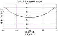
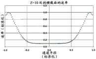
对于诸如水消毒的应用,UV-LED反应器通常可用于照射流体。然而,在典型的UV-LED反应器中,辐射功率分布存在相当大的变化,导致不均匀的辐射通量率分布(轮廓),这在一些情况下可能非常明显。通量率(单位为W/m2)是从所有方向通过无限小的横截面积dA的球体的辐射通量(功率)除以dA。此外,通常存在流体速率分布的变化,在流体行进通过反应器时导致流体的停留时间分布。这两种通量率分布和速率分布现象中的任何一种或这两种现象的组合可能导致在流体元件通过反应器时相当宽的UV剂量分布范围递送给流体元件。UV通量率分布和速率分布的变化(速率分布与停留时间分布有关)可能导致部分流体穿过UV反应器而没有接收到足够的UV剂量(UV通量率和停留时间的乘积),这在UV反应器领域中是已知的问题并且可以称为“短路”。短路会对UV反应器的性能产生明显不利的影响。For applications such as water disinfection, UV-LED reactors can often be used to irradiate fluids. However, in a typical UV-LED reactor, there is considerable variation in the radiant power distribution, resulting in an inhomogeneous radiant flux rate distribution (profile), which can be very pronounced in some cases. The flux rate (in W/m2 ) is the radiant flux (power) from all directions through a sphere of infinitesimal cross-sectional area dA divided by dA. In addition, there are typically variations in the fluid velocity profile, resulting in a residence time profile of the fluid as it travels through the reactor. Either or a combination of these two phenomena of flux rate distribution and velocity distribution may result in the delivery of a relatively wide range of UV dose distributions to the fluidic element as it passes through the reactor. Variations in UV flux rate distribution and velocity distribution (velocity distribution is related to residence time distribution) may result in part of the fluid passing through the UV reactor without receiving sufficient UV dose (product of UV flux rate and residence time), which in This is a known problem in the field of UV reactors and may be referred to as "shorting". Short circuits can have a significant adverse effect on the performance of the UV reactor.
人们普遍希望提高或增强在流体通过UV反应器时输送到流体的剂量均匀性。It is generally desirable to improve or enhance the uniformity of dose delivered to a fluid as it passes through a UV reactor.
相关技术的前述示例和与其相关的限制旨在是说明性的而且是非排他性的。在阅读说明书并研究附图之后,相关技术的其它限制对于本领域技术人员将变得显而易见。The foregoing examples of related art and limitations associated therewith are intended to be illustrative and not exclusive. Other limitations of the related art will become apparent to those skilled in the art upon reading the specification and studying the drawings.
发明内容Contents of the invention
结合系统、工具和方法来描述和说明以下方面,这些系统、工具和方法旨在是示例性和说明性的而不限制范围。在一些方面,已经减少或消除了一个或多个上述问题,而其它方面则针对于其它改进。The following aspects are described and illustrated in conjunction with systems, tools and methods, which are intended to be exemplary and illustrative and not limiting in scope. In some aspects, one or more of the above-mentioned problems have been reduced or eliminated, while other aspects are directed to other improvements.
本发明的一个方面提供了一种同时控制流体和光学环境的UV-LED反应器。该UV-LED反应器可以有利地以小占地面积向流体流提供具有高均匀度(相对于现有技术的UV反应器)的辐射剂量,并且可以有利地提供比至少一些现有技术的反应器更高效和紧凑的UV-LED反应器。可以将该UV-LED反应器结合到用于各种UV光反应应用——包括例如基于UV的水处理等(如下文进一步详细说明)——的装置中。One aspect of the present invention provides a UV-LED reactor that simultaneously controls the fluid and optical environment. The UV-LED reactor can advantageously provide a radiation dose to a fluid stream with high uniformity (relative to prior art UV reactors) in a small footprint, and can advantageously provide better response than at least some prior art LED reactors. A more efficient and compact UV-LED reactor. The UV-LED reactor can be incorporated into devices for various UV light reaction applications including, for example, UV-based water treatment, etc. (as further detailed below).
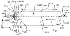
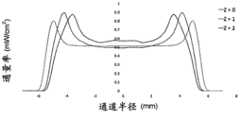
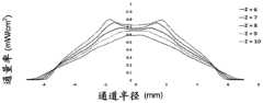
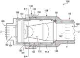
本公开的一个方面提供了一种紫外线(UV)反应器,其包括:流体管道,该流体管道至少部分地由限定管道的外壁限定,以容许流体流过其中;固态UV发射器(例如紫外线发光二极管或UV-LED);以及包括一个或多个透镜的辐射聚焦元件。流体管道可包括流体入口和流体出口以及位于入口与出口之间的纵向延伸的流体流动通道。流体流动通道可沿纵向方向延伸,以容许流体在纵向方向上流过流体流动通道的内孔。流体流动通道可具有通道中心轴线,该通道中心轴线至少在内孔的纵向中间部分中在纵向方向上延伸穿过的内孔的横截面的形心。可以将一个或多个透镜定位在从固态UV发射器发射的辐射的辐射路径中,以引导来自固态UV发射器的辐射入射在流体流动通道中并由此提供流体流动通道的内孔内的辐射通量率分布。所述一个或多个透镜可以构造成提供辐射通量率分布,其中,当固态UV发射器发射辐射时,对于流体流动通道的内孔的相对靠近固态UV发射器定位的截面而言(例如,对于第一截面而言),辐射通量率分布在离通道中心轴线(即,流体流动通道的内孔的中心轴线或至少流体流动通道的内孔纵向中间部分的中心轴线)相对远的位置处相对高,并且在较靠近通道中心轴线的位置处相对较低,并且其中,对于流体流动通道的内孔的相对远离固态UV发射器定位的横截面而言(例如,对于比第一横截面更远离固态UV发射器定位的第二横截面而言),辐射通量率分布在离通道中心轴线相对远的位置处相对低并且在相对靠近通道中心轴线的位置处相对高。One aspect of the present disclosure provides an ultraviolet (UV) reactor comprising: a fluid conduit at least partially defined by an outer wall defining the conduit to allow fluid to flow therethrough; a solid state UV emitter (e.g., an ultraviolet light emitting diodes or UV-LEDs); and a radiation focusing element comprising one or more lenses. The fluid conduit may include a fluid inlet and a fluid outlet and a longitudinally extending fluid flow channel between the inlet and the outlet. The fluid flow channel may extend in a longitudinal direction to allow fluid to flow through the bore of the fluid flow channel in the longitudinal direction. The fluid flow channel may have a channel center axis extending at least in the longitudinal middle portion of the inner bore in the longitudinal direction through the centroid of a cross-section of the inner bore. One or more lenses may be positioned in the radiation path of the radiation emitted from the solid state UV emitter to direct the radiation from the solid state UV emitter to be incident in the fluid flow channel and thereby provide radiation within the bore of the fluid flow channel Flux rate distribution. The one or more lenses may be configured to provide a radiant flux rate distribution wherein, when the solid-state UV emitter emits radiation, for a section of the bore of the fluid flow channel that is located relatively close to the solid-state UV emitter (e.g., For the first section), the radiation flux rate is distributed at a position relatively far from the central axis of the channel (i.e., the central axis of the inner bore of the fluid flow channel or at least the central axis of the inner bore longitudinal middle portion of the fluid flow channel) relatively high, and relatively low at a position closer to the central axis of the channel, and wherein, for cross-sections of the inner bore of the fluid flow channel that are positioned relatively far from the solid-state UV emitter (for example, for For a second cross-section located away from the solid-state UV emitter), the radiant flux rate distribution is relatively low at locations relatively far from the central axis of the channel and relatively high at locations relatively close to the central axis of the channel.
本公开的另一方面是一种紫外线(UV)反应器,其包括:流体管道,该流体管道至少部分地由限定管道的外壁限定,以容许流体流过其中;固态UV发射器(例如紫外线发光二极管或UV-LED);以及包括一个或多个透镜的辐射聚焦元件;其中,所述流体管道包括流体入口、流体出口和位于入口与出口之间的纵向延伸的流体流动通道,流体流动通道在纵向方向上延伸,以容许所述流体在纵向方向上流过流体流动通道的内孔;其中,所述一个或多个透镜位于从固态UV发射器发射的辐射的辐射路径中,以引导来自固态UV发射器的辐射入射在流体流动通道中并由此提供流体流动通道的内孔内的辐射通量率分布;并且其中,固态UV发射器在UV发射器的辐射路径中具有中心光轴,该中心光轴在纵向方向上从固态UV发射器的发射区域的形心延伸通过一个或多个光学透镜的形心,并且当固态UV发射器正在发射辐射时:对于固态UV发射器的辐射路径中相对靠近固态UV发射器的位置,辐射通量率分布在离中心光轴较远的位置处相对高,而在较靠近中心光轴的位置处相对低;并且对于固态UV发射器的辐射路径中离固态UV发射器相对远的位置处,辐射通量率分布在离中心光轴相对远的位置处相对低,而在较靠近中心光轴的位置处相对高。Another aspect of the present disclosure is an ultraviolet (UV) reactor comprising: a fluid conduit at least partially defined by an outer wall defining the conduit to allow fluid to flow therethrough; a solid state UV emitter (e.g., an ultraviolet light emitting diode or UV-LED); and a radiation focusing element comprising one or more lenses; wherein the fluid conduit comprises a fluid inlet, a fluid outlet, and a longitudinally extending fluid flow channel between the inlet and the outlet, the fluid flow channel being Extending in a longitudinal direction to allow the fluid to flow through the inner bore of the fluid flow channel in the longitudinal direction; wherein the one or more lenses are positioned in the radiation path of the radiation emitted from the solid state UV emitter to guide radiation from the solid state UV emitter. Radiation from the emitter is incident on the fluid flow channel and thereby provides a radiant flux rate distribution within the bore of the fluid flow channel; and wherein the solid state UV emitter has a central optical axis in the radiation path of the UV emitter, the center The optical axis extends in the longitudinal direction from the centroid of the emitting area of the solid-state UV emitter through the centroid of the one or more optical lenses, and when the solid-state UV emitter is emitting radiation: for the opposite in the radiation path of the solid-state UV emitter Closer to the solid-state UV emitter, the radiant flux rate distribution is relatively high at positions farther from the central optical axis and relatively lower at positions closer to the central optical axis; Where the solid state UV emitter is relatively far away, the radiant flux rate distribution is relatively low at positions relatively far from the central optical axis and relatively high at positions closer to the central optical axis.
固态UV发射器可以包括多个固态发射器。所述一个或多个透镜可以通过以下一者或多者而被构造,以提供具有这些特性的辐射通量率分布:从多种透镜类型中选择一个或多个透镜、一个或多个透镜的形状(例如,透镜的厚度和透镜表面的曲率)、一个或多个透镜的位置和一个或多个透镜的折射率。在一些方面,透镜可以包括光学上邻近UV发射器的会聚透镜和与会聚透镜相距某个合适距离的准直透镜。在一些方面,透镜可以包括会聚透镜和准直透镜,该会聚透镜被定位成接收来自UV发射器的辐射,其中该准直透镜可以被定位在与从会聚透镜发出的辐射的焦点的距离小于其焦距的距离处(例如,相差距离差Δ)。在一些方面,透镜可以包括:接收来自UV发射器的辐射的半球形透镜以及接收来自该半球形透镜的辐射的平凸透镜,两者的平面侧都面向UV发射器,且两者的光轴都与通道中心轴线同轴。在一些方面,在平凸透镜与流体流动通道的内孔中的流体之间存在气隙。在一些方面,在平凸透镜与流体流动通道的内孔中的流体之间存在气隙和透UV(例如石英)窗口。A solid state UV emitter may include multiple solid state emitters. The one or more lenses may be configured to provide a radiant flux rate distribution having these properties by one or more of: selecting one or more lenses from a variety of lens types; The shape (eg, the thickness of the lens and the curvature of the lens surface), the location of the one or more lenses, and the refractive index of the one or more lenses. In some aspects, the lens can include a converging lens optically adjacent to the UV emitter and a collimating lens some suitable distance from the converging lens. In some aspects, the lens can include a converging lens positioned to receive radiation from the UV emitter and a collimating lens, wherein the collimating lens can be positioned less than a distance from the focal point of the radiation emitted from the converging lens. At the distance of the focal length (for example, the difference distance difference Δ). In some aspects, the lens can include a hemispherical lens receiving radiation from the UV emitter and a plano-convex lens receiving radiation from the hemispherical lens, both with their planar sides facing the UV emitter and with their optical axes Coaxial with the central axis of the channel. In some aspects, an air gap exists between the plano-convex lens and the fluid in the bore of the fluid flow channel. In some aspects, there is an air gap and a UV transparent (eg, quartz) window between the plano-convex lens and the fluid in the bore of the fluid flow channel.
在一些方面,平凸透镜可被定位在与从半球形透镜发射的辐射的焦点的距离小于其固有焦距f1的距离f’处。平凸透镜相对于半球形透镜的焦点的间距(f’)可以比平凸透镜的固有焦距(f1)小距离差(Δ)。在一些方面,该距离差Δ在平凸透镜的焦距f1的10%-35%的范围内。在一些方面,该距离差Δ在平凸透镜的焦距(f1)的15%-30%的范围内。在一些方面,该距离差Δ在平凸透镜的焦距(f1)的20%-30%的范围内。透镜可以包括双凸、双凹、平凸、平凹、弯月形或半球形透镜的任何合适的组合。透镜可以包括第一透镜(位置较靠近UV发射器)和第二透镜(位置相对远离UV发射器)。从第一透镜发射的辐射可以具有焦点,并且第二透镜可以具有固有焦距(f1),但第二透镜可以不位于离第一透镜的焦点的距离(f1)处。替代地,第二透镜可以位于离第一透镜的焦点的距离(f’)处,其中f’比f1小距离差Δ。在一些方面,该距离差Δ在第二透镜的焦距f1的10%-35%的范围内。在一些方面,该距离差Δ在第二透镜的焦距f1的15%-30%的范围内。在一些方面,该距离差Δ在第二透镜的焦距f1的20%-30%的范围内。In some aspects, the plano-convex lens can be positioned at a distance f' from the focal point of radiation emitted from the hemispherical lens that is less than its intrinsic focal length fl. The distance (f') of the plano-convex lens relative to the focal point of the hemispherical lens can be smaller than the intrinsic focal length (f1) of the plano-convex lens by a distance difference (Δ). In some aspects, the distance difference Δ is in the range of 10%-35% of the focal length fl of the plano-convex lens. In some aspects, the distance difference Δ is in the range of 15%-30% of the focal length (f1) of the plano-convex lens. In some aspects, the distance difference Δ is in the range of 20%-30% of the focal length (f1) of the plano-convex lens. The lenses may comprise any suitable combination of biconvex, biconcave, plano-convex, plano-concave, meniscus, or hemispherical lenses. The lenses may include a first lens (located closer to the UV emitter) and a second lens (located relatively far from the UV emitter). Radiation emitted from the first lens may have a focus and the second lens may have an intrinsic focal length (f1), but the second lens may not be located at a distance (f1) from the focus of the first lens. Alternatively, the second lens may be located at a distance (f') from the focus of the first lens, where f' is smaller than f1 by a distance difference Δ. In some aspects, the distance difference Δ is in the range of 10%-35% of the focal length fl of the second lens. In some aspects, the distance difference Δ is in the range of 15%-30% of the focal length fl of the second lens. In some aspects, the distance difference Δ is in the range of 20%-30% of the focal length fl of the second lens.
限定内孔的壁可以被成形为将流体流动通道的内孔限定为在流体流动通道的至少纵向中间部分上具有柱形形状,该纵向中间部分与流体入口和流体出口间隔开。该柱形形状可以包括具有圆形横截面的圆柱体或具有某种其它(例如矩形或另一种多边形)横截面的柱体。固态UV发射器的主光轴(例如,LED的主光轴)、一个或多个透镜的光轴和通道中心轴线可以是共线的或同轴的。流体入口可以包括:一个或多个入口孔口,流体入口在此处通入流体流动通道中;一个或多个连接孔口,UV反应器可以通过所述连接孔口连接到向反应器提供流体的外部流体系统;以及可以在入口孔口与连接孔口之间延伸的一个或多个入口管道。类似地,流体出口可以包括:一个或多个出口孔口,流体出口在此处通入流体流动通道中;一个或多个连接孔口,UV反应器可以通过所述连接孔口连接到从反应器向其提供流体的外部流体输出系统;以及可以在出口孔口与连接孔口之间延伸的一个或多个出口管道。The wall defining the bore may be shaped to define the bore of the fluid flow channel to have a cylindrical shape over at least a longitudinally intermediate portion of the fluid flow channel that is spaced from the fluid inlet and the fluid outlet. The cylindrical shape may comprise a cylinder with a circular cross-section or a cylinder with some other (eg rectangular or another polygonal) cross-section. The principal optical axis of the solid state UV emitter (eg, that of the LED), the optical axis of the one or more lenses, and the central axis of the channel can be collinear or coaxial. The fluid inlet may include: one or more inlet orifices, where the fluid inlet opens into the fluid flow channel; one or more connection orifices, through which the UV reactor may be connected to supply fluid to the reactor; and one or more inlet conduits that may extend between the inlet port and the connection port. Similarly, the fluid outlet can include: one or more outlet ports, where the fluid outlet opens into the fluid flow channel; one or more connection ports, through which the UV reactor can be connected to the an external fluid output system to which the device provides fluid; and one or more outlet conduits which may extend between the outlet aperture and the connection aperture.
固态UV发射器和辐射聚焦元件可以容纳在合适的壳体中,该壳体可以包括透UV部件,例如石英窗,用于将电子器件和光学器件与流体流分开。The solid state UV emitter and radiation focusing elements may be housed in a suitable housing which may include UV transparent components, such as quartz windows, to separate the electronics and optics from the fluid flow.
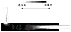
在一些方面,固态UV发射器可以定位成相对靠近流体出口并且相对远离流体入口,其中固态发射器的主光轴定向为大致与纵向流体流动方向逆平行。流体管道可在其一个端部处包括横截面壁,该横截面壁可限定流体入口的入口孔口(在此流体入口通入流体流动通道中)或可以其它方式支承流体入口。入口孔口和/或流体入口可以居中地位于横截面壁中。通道中心轴线可穿过入口孔口和/或流体入口伸出。入口孔口和/或流体入口的横截面可以关于位于通道中心轴线上的点呈圆形对称。在入口孔口和/或流体入口显示出这些特性的情况下,对于流体流动通道的内孔的位置相对远离固态UV发射器或靠近入口孔口的横截面而言,流体速率在相对远离通道中心轴线的位置处相对低并且在相对靠近通道中心轴线的位置处相对高。固态UV发射器可以被支承在壳体中,使得固态UV发射器的主光轴至少大致与通道中心轴线对齐。在一些方面,外壳本身可以被支承(例如,由一个或多个托架支承),使得固态UV发射器的主光轴至少大致与通道中心轴线对齐。一个或多个托架可以从流体管道的限定管道的外壁延伸到壳体。所述一个或多个托架可跨流体出口的出口管道延伸。流体出口的出口孔口可以由限定管道的外壁(可能包括限定内孔的壁)、壳体和/或所述一个或多个托架(如果存在)的组合限定,或者流体出口可以由限定管道的外壁(可能包括限定内孔的壁)、壳体和/或所述一个或多个托架(如果存在)的组合以其它方式支承。在一些方面,流体出口的出口管道可以在出口孔口与连接孔口之间的位置处具有大致环形的横截面,其中这些横截面可由限定管道的外壁和壳体(该环形形状被所述一个或多个托架中断的区域除外)限定。这种横截面(用于出口管道的大致环形的横截面)不是必须的。利用这些构型,出口孔口可以位于与通道中心轴线横向间隔开的位置处(例如,流体流动通道的内孔或一般而言流体管道所容许的尽可能横向远离)。因此,在出口孔口和/或流体出口表现出这些特性的情况下,对于流体流动通道的内孔的位置相对靠近固态UV发射器或靠近出口孔口的横截面而言,流体速率在离通道中心轴线相对远的至少一些位置处(例如,在出口孔口的直接上游或附近的位置处)相对高,而在相对靠近通道中心轴线的位置处则相对低。In some aspects, the solid state UV emitters can be positioned relatively close to the fluid outlet and relatively far from the fluid inlet, wherein the major optical axis of the solid state emitter is oriented generally antiparallel to the longitudinal fluid flow direction. The fluid conduit may include at one end thereof a cross-sectional wall which may define an inlet aperture of the fluid inlet where it opens into the fluid flow channel or which may otherwise support the fluid inlet. The inlet orifice and/or the fluid inlet may be located centrally in the cross-sectional wall. The channel central axis may protrude through the inlet aperture and/or the fluid inlet. The cross-section of the inlet orifice and/or the fluid inlet may be circularly symmetrical about a point lying on the central axis of the channel. Where the inlet orifice and/or fluid inlet exhibit these characteristics, for a cross-section of the bore of the fluid flow channel located relatively far from the solid-state UV emitter or close to the inlet orifice, the fluid velocity is relatively far from the center of the channel. The axis is relatively low at a position and relatively high at a position relatively close to the central axis of the channel. The solid state UV emitter may be supported in the housing such that the principal optical axis of the solid state UV emitter is at least approximately aligned with the central axis of the channel. In some aspects, the housing itself can be supported (eg, by one or more brackets) such that the major optical axis of the solid state UV emitter is at least approximately aligned with the channel central axis. One or more brackets may extend from the conduit-defining outer wall of the fluid conduit to the housing. The one or more brackets may extend across the outlet conduit of the fluid outlet. The outlet orifice of the fluid outlet may be defined by a combination of the outer wall defining the duct (possibly including the wall defining the inner bore), the housing and/or the one or more brackets (if present), or the fluid outlet may be defined by the duct The combination of the outer wall (possibly including the wall defining the inner bore), the housing and/or the one or more brackets (if present) is otherwise supported. In some aspects, the outlet conduit of the fluid outlet can have a generally annular cross-section at a location between the outlet aperture and the connection aperture, wherein these cross-sections can be defined by the outer wall of the conduit and the housing (the annular shape being defined by the one or multiple bays interrupted by the area) defined. This cross section (substantially circular cross section for the outlet duct) is not necessary. With these configurations, the outlet orifice may be located at a location laterally spaced from the central axis of the channel (eg, as laterally as far away as the bore of the fluid flow channel or generally the fluid conduit will allow). Thus, where the outlet orifice and/or fluid outlet exhibit these characteristics, for a cross-section of the bore of the fluid flow channel that is located relatively close to the solid state UV emitter or close to the outlet orifice, the fluid velocity varies from channel to channel. At least some locations relatively far from the central axis (eg, at locations immediately upstream or near the outlet orifice) are relatively high, and relatively low at locations relatively close to the central axis of the channel.
在一些方面,固态UV发射器可以定位成相对靠近流体入口并且相对远离流体出口,其中固态发射器的主光轴定向成大致平行于纵向流体流动方向。流体管道可在其一个端部处包括横截面壁,该横截面壁可限定流体出口的出口孔口(在此流体出口通向流体流动通道中)或可以其它方式支承流体出口。出口孔口和/或流体出口可以居中地位于横截面壁中。通道中心轴线可穿过出口孔口和/或流体出口伸出。出口孔口和/或流体出口的横截面可以关于位于通道中心轴线上的点呈圆形对称。在出口孔口和/或流体出口表现出这些特性的情况下,对于流体流动通道的内孔的位置相对靠近出口孔口的横截面而言,流体速率在相对远离通道中心轴线的位置处相对低,而在相对靠近通道中心轴线的位置处则相对高。固态UV发射器可以被支承在壳体中,使得固态UV发射器的主光轴至少大致与通道中心轴线对齐。在一些方面,壳体本身可以被支承(例如,由一个或多个托架40支承),以使得固态UV发射器的主光轴至少大致与通道中心轴线对齐。所述一个或多个托架可以从流体管道的限定管道的外壁延伸到壳体。所述一个或多个托架可跨流体入口的入口管道延伸。流体入口的入口孔口可以由限定管道的外壁(可能包括限定内孔的壁)、壳体和/或所述一个或多个托架(如果存在)的组合限定,或者流体入口可以由限定管道的外壁(可能包括限定内孔的壁)、壳体和/或所述一个或多个托架(如果存在)的组合以其它方式支承。在一些方面,流体入口的入口管道可在入口孔口与连接孔口之间的位置处具有大致环形的横截面,其中这些横截面可由限定管道的外壁和壳体(该环形形状被所述一个或多个托架中断的区域除外)限定。这种横截面(用于入口管道的大致环形的横截面)不是必要的。利用这些构型,入口孔口可以位于与通道中心轴线横向间隔开的位置处(例如,流体流动通道的内孔或一般而言流体管道所容许的尽可能横向远离)。因此,在入口孔口和/或流体入口表现出这些特性的情况下,对于流体流动通道的内孔的位置相对靠近固态UV发射器或靠近入口孔口的横截面而言,流体速率在离通道中心轴线相对远的至少一些位置处(例如,在入口孔口的直接下游或附近的位置处)相对高,而在相对靠近通道中心轴线的位置处则相对低。In some aspects, the solid state UV emitters can be positioned relatively close to the fluid inlet and relatively far from the fluid outlet, wherein the major optical axes of the solid state emitters are oriented generally parallel to the longitudinal fluid flow direction. The fluid conduit may include at one end thereof a cross-sectional wall which may define an outlet aperture of the fluid outlet (where the fluid outlet opens into the fluid flow channel) or may otherwise support the fluid outlet. The outlet orifice and/or the fluid outlet may be located centrally in the cross-sectional wall. The channel central axis may protrude through the outlet aperture and/or the fluid outlet. The cross-section of the outlet orifice and/or the fluid outlet may be circularly symmetrical about a point lying on the central axis of the channel. Where the outlet orifice and/or fluid outlet exhibits these characteristics, for a fluid flow channel where the bore is located relatively close to the cross-section of the outlet orifice, the fluid velocity is relatively low at a location relatively far from the central axis of the channel , while it is relatively high at a position relatively close to the central axis of the channel. The solid state UV emitter may be supported in the housing such that the principal optical axis of the solid state UV emitter is at least approximately aligned with the central axis of the channel. In some aspects, the housing itself can be supported (eg, by one or more brackets 40 ) such that the major optical axis of the solid state UV emitter is at least approximately aligned with the channel central axis. The one or more brackets may extend from a conduit-defining outer wall of the fluid conduit to the housing. The one or more brackets may extend across the inlet conduit of the fluid inlet. The inlet aperture of the fluid inlet may be defined by a combination of the outer wall defining the duct (possibly including the wall defining the inner bore), the housing and/or the one or more brackets (if present), or the fluid inlet may be defined by the duct The combination of the outer wall (possibly including the wall defining the inner bore), the housing and/or the one or more brackets (if present) is otherwise supported. In some aspects, the inlet conduit of the fluid inlet can have a generally annular cross-section at a location between the inlet aperture and the connection aperture, wherein these cross-sections can be defined by the outer wall of the conduit and the housing (the annular shape being defined by the one or multiple bays interrupted by the area) defined. Such a cross-section (a substantially circular cross-section for the inlet duct) is not necessary. With these configurations, the inlet orifice may be located at a location spaced laterally from the central axis of the channel (eg, as laterally as far away as the bore of the fluid flow channel or, in general, the fluid conduit will allow). Thus, where the inlet orifice and/or the fluid inlet exhibits these characteristics, for a cross-section of the bore of the fluid flow channel that is located relatively close to the solid state UV emitter or close to the inlet orifice, the fluid velocity varies from channel to channel. At least some locations relatively far from the central axis (eg, at locations immediately downstream of or near the inlet orifice) are relatively high, and relatively low at locations relatively close to the central axis of the channel.
UV反应器可包括可位于流体流动通道中的一个或多个流动调节器(例如静态混合器或其它类型的流动调节器)。流动调节器可以相对贴近流体入口定位,并且可以成形为利用流体流的动量来引导流体流。在一些方面,可以将平坦或弯曲形状的挡板或环定位在流体的朝向低辐射通量率的区域的那部分的路径中,以重定向流体流的至少一部分的流动路线或降低在朝向低辐射通量率的区域的方向上的流速。由此,这样的流动调节器可以在流体流动通道的一部分上引起流体流动通道的辐射通量率相对低的区域中的相对低的流体速率和/或在流体流动通道的辐射通量率相对低和相对高的区域之间产生流动混合。在入口孔口和/或流体入口居中地位于横截面壁中的情况下,所述一个或多个流动调节器可以位于流体流动通道的存在流体流膨胀(例如,从具有比纵向中间部分的横截面小的横截面的入口起)的区域中,并且可以使用流动动量,该流动动量是入口或流体流动通道的入口附近的区域处的相对高的速率的结果。在这些区域中,可以将平坦或弯曲形状的挡板或环定位在流体的走向低辐射通量率的区域的那部分的路径中,以重定向至少一部分的流体流的流动路线或降低在朝向低辐射通量率的区域的方向上的流速。由此,这样的流动调节器可以在流体流动通道的一部分上引起流体流动通道的辐射通量率相对低的区域中的相对低的流体速率和/或在流体流动通道的辐射通量率相对低和相对高的区域之间产生流动混合。静态混合器形式的流动调节器可导致流体流中形成涡流或旋涡。例如,由于将三角翼形状的混合器和/或扭带形状的混合器定位在流体流的路径中,所以可在流体流动通道中产生反向旋转的涡流。The UV reactor can include one or more flow regulators (eg, static mixers or other types of flow regulators) that can be located in the fluid flow channels. The flow conditioner can be positioned relatively close to the fluid inlet and can be shaped to use the momentum of the fluid flow to direct the fluid flow. In some aspects, a baffle or ring of flat or curved shape can be positioned in the path of that portion of the fluid towards the region of low radiant flux rate to redirect at least a portion of the flow path of the fluid flow or reduce the flow path in the direction of the low radiant flux rate. The radiant flux rate is the flow velocity in the direction of the area. Thus, such a flow conditioner may induce a relatively low fluid velocity in a region of the fluid flow channel where the radiant flux rate is relatively low over a portion of the fluid flow channel and/or where the radiant flux rate is relatively low in the fluid flow channel. and relatively high areas generate flow mixing. Where the inlet orifice and/or fluid inlet is centrally located in the cross-sectional wall, the one or more flow regulators may be located in the presence of fluid flow expansion of the fluid flow channel (e.g., In the region from the inlet of the small cross-section), and the flow momentum may be used as a result of the relatively high velocity at the inlet or the region near the inlet of the fluid flow channel. In these regions, baffles or rings of flat or curved shape may be positioned in the path of that portion of the fluid towards the region of low radiant flux rate to redirect at least a portion of the flow path of the fluid flow or reduce the flow path towards the Flow velocity in the direction of the region of low radiant flux rate. Thus, such a flow conditioner may induce a relatively low fluid velocity in a region of the fluid flow channel where the radiant flux rate is relatively low over a portion of the fluid flow channel and/or where the radiant flux rate is relatively low in the fluid flow channel. and relatively high areas generate flow mixing. Flow regulators in the form of static mixers can cause vortices or eddies to form in the fluid stream. For example, counter-rotating vortices may be created in the fluid flow channel due to the positioning of delta wing shaped mixers and/or twisted ribbon shaped mixers in the path of the fluid flow.
流动调节器可包括一个或多个静态混合器,其又可包括一个或组合的、彼此相邻的多个三角翼形状的混合器和/或扭带形状的混合器。三角翼形状的混合器和/或扭带形状的混合器可以在一些部位彼此连接;例如,在基部或顶点处。在流体流动通道的一部分上产生涡流或旋涡,特别是反向旋转的涡流,可以提供流体流的混合,并且可以导致流体的相同部分在较高和较低辐射通量率的区域中行进。在一些方面,可以应用一个或多个流动调节器来防止流体在流体流动通道的具有低通量率的区域中高速流动或使流动从流体流动通道的这些具有低通量率的区域重定向到流体流动通道的具有较高通量率的区域。例如,如果流体流动通道的靠近限定内孔的壁的一些区域中的通量率低,则可以设置从限定内孔的壁向通道中心轴线突伸的环,以将流体流朝向通道中心轴线重定向并增强混合。在一些方面,可以将一个或多个流动调节器放置在流体流动通道的辐射通量率低的区域,例如,在管道12的一些部位的、限定管道的壁附近(例如,限定内孔的壁附近),或在流体入口中。在流体流动通道的具有低通量率的区域中配置流动调节器(例如静态混合器)可以使流动调节器对阻挡UV辐射的影响最小化。在一些方面,流动调节器可以由UV反射材料制成。在一些方面,流动调节器可以由透UV材料制成。The flow conditioner may comprise one or more static mixers, which in turn may comprise one or a combination of a plurality of delta wing shaped mixers and/or twisted ribbon shaped mixers adjacent to each other. Delta wing shaped mixers and/or twisted ribbon shaped mixers may be connected to each other at some point; for example, at the base or apex. Creating a vortex or vortex, particularly a counter-rotating vortex, on a portion of a fluid flow channel can provide mixing of the fluid flow and can cause the same portion of the fluid to travel in regions of higher and lower radiant flux rates. In some aspects, one or more flow regulators may be employed to prevent high velocity fluid flow in or redirect flow from these regions of the fluid flow channel with low flux rates to A region of a fluid flow channel with a higher flux rate. For example, if the flux rate is low in some regions of the fluid flow channel near the walls defining the bore, an annulus projecting from the walls defining the bore toward the central axis of the channel may be provided to redirect the fluid flow toward the central axis of the channel. Orients and enhances mixing. In some aspects, one or more flow regulators may be placed in areas of the fluid flow path where the radiant flux rate is low, for example, near portions of the
UV反应器可以包括第二固态UV发射器;以及第二辐射聚焦元件,其包括一个或多个辅助/第二透镜。一个或多个辅助/第二透镜可以位于从第二固态UV发射器发射的辐射的第二辐射路径中,以引导来自第二固态UV发射器的辐射入射在于流体流动通道中流动的流体上并由此提供流体流动通道的内孔内的第二辐射通量率分布。所述一个或多个第二透镜可以构造成提供第二辐射通量率分布,其中,对于流体流动通道的内孔的位置相对靠近第二固态UV发射器的第二横截面而言(例如,对于第一辅助横截面而言),第二辐射通量率分布在离通道中心轴线相对远的位置处相对高,而在较靠近通道中心轴线的位置处则相对低,并且其中,对于流体流动通道的内孔的位置相对远离第二固态UV发射器的辅助横截面而言(例如,对于位置比第一辅助横截面更远离第二固态UV发射器的第二辅助横截面而言),第二辐射通量率分布在离通道中心轴线相对远的位置处相对低,而在较靠近通道中心轴线的位置处相对高。第二固态UV发射器的主光轴可以与(第一)固态UV发射器的主光轴逆平行。(第一)固态UV发射器的主光轴(例如,第一LED的主光轴)、第二固态UV发射器的主光轴(例如,第二LED的主光轴)、所述一个或多个透镜的光轴、所述一个或多个辅助/第二透镜的光轴以及流体流动通道的至少纵向中间部分的中心轴线可以是共线的或同轴的。第二固态UV发射器、第二辐射聚焦元件和所述一个或多个辅助/第二透镜可包括固态发射器、辐射聚焦元件和所述一个或多个透镜的任何特征。The UV reactor may include a second solid state UV emitter; and a second radiation focusing element including one or more auxiliary/secondary lenses. One or more auxiliary/secondary lenses may be located in the second radiation path of the radiation emitted from the second solid state UV emitter to direct the radiation from the second solid state UV emitter to be incident on the fluid flowing in the fluid flow channel and A second radiant flux rate distribution within the bore of the fluid flow channel is thereby provided. The one or more second lenses may be configured to provide a second radiant flux rate distribution wherein for a location of the bore of the fluid flow channel relatively close to a second cross-section of the second solid state UV emitter (e.g., For the first auxiliary cross-section), the second radiation flux rate distribution is relatively high at a position relatively far from the central axis of the channel, and relatively low at a position closer to the central axis of the channel, and wherein, for the fluid flow For the location of the bore of the channel relative to the auxiliary cross-section of the second solid-state UV emitter (e.g., for the second auxiliary cross-section located farther from the second solid-state UV emitter than the first auxiliary cross-section), the second The second radiation flux rate distribution is relatively low at positions relatively far from the central axis of the channel, and relatively high at positions closer to the central axis of the channel. The main optical axis of the second solid state UV emitter may be antiparallel to the main optical axis of the (first) solid state UV emitter. The principal optical axis of the (first) solid state UV emitter (e.g., the principal optical axis of the first LED), the principal optical axis of the second solid state UV emitter (e.g., the principal optical axis of the second LED), the one or The optical axes of the plurality of lenses, the optical axes of the one or more secondary/secondary lenses and the central axis of at least the longitudinal middle portion of the fluid flow channel may be collinear or coaxial. The second solid state UV emitter, the second radiation focusing element and the one or more secondary/second lenses may comprise any of the features of the solid state emitter, the radiation focusing element and the one or more lenses.
在一些方面,流体出口可以包括流体出口管道,该流体出口管道可以部分地由壳体限定或以其它方式与壳体直接或间接地热接触,壳体又可以直接或间接地(例如,经由印刷电路板(PCB))与固态UV发射器热接触(即在壳体或其一部分的横向侧面以及固态UV发射器的与固态UV发射器或其一部分的主光轴相反的侧面上),以从固态UV发射器中除去热量并将这种热量传递给流体。在一些方面,流体出口可包括流体出口管道,该流体出口管道以其它方式与固态UV发射器直接或间接地(例如,经由印刷电路板(PCB))热接触,以从固态UV发射器除去热量并将这种热量传递给流体。在一些方面,UV发射器安装在其上的印刷电路板(PCB)可以提供壳体和/或出口管道或其一部分的壁,使得流体与UV发射器安装在其上的PCB直接热接触。当流体从流体流动通道的内孔被引入相对窄的流体出口时,由于流动收缩和流体速率的突然变化导致的高混合程度,这种散热可以是特别有效的。在一些方面,流体入口可包括流体入口管道,该流体入口管道可部分地由壳体限定或以其它方式与壳体直接或间接地热接触,壳体又可以与固态UV发射器直接或间接地(例如,经由印刷电路板(PCB))进行热接触(即在壳体或其一部分的横向侧面上和/或在固态UV发射器的与固态UV发射器或其一部分的主光轴相反的侧面上),以从固态UV发射器中除去热量并将这种热量传递给流体。在一些方面,流体入口可包括流体入口管道,该流体入口管道以其它方式与固态UV发射器直接或间接地(例如,经由印刷电路板(PCB))热接触,以从固态UV发射器除去热量并将这种热量传递给流体。在一些方面,UV发射器安装在其上的印刷电路板(PCB)可以提供壳体和/或入口管道或其一部分的壁,使得流体与UV发射器安装在其上的PCB直接热接触。当流体流从窄流体入口被引入流体流动通道的内孔的相关侧时,由于流动扩展和流体速率的突然变化导致的高混合程度,这种散热可以是特别有效的。由于热量是从壳体的许多表面和相应的表面区域中除去的,所以这种热传递(从壳体或其一部分的周壁)会是特别有效的。而且,通过控制入口/出口管道的横截面,可以在壳体壁附近获得更高的流体速率,以进一步增强热传递。In some aspects, the fluid outlet can include a fluid outlet conduit that can be partially defined by or otherwise be in direct or indirect thermal contact with the housing, which in turn can be directly or indirectly (e.g., via a printed circuit board (PCB)) in thermal contact with the solid-state UV emitter (i.e. on the lateral sides of the housing or a portion thereof and on the side of the solid-state UV emitter opposite the principal optical axis of the solid-state UV emitter or a portion thereof) to Heat is removed from the UV emitter and transferred to the fluid. In some aspects, the fluid outlet can include a fluid outlet conduit that is otherwise in direct or indirect thermal contact (e.g., via a printed circuit board (PCB)) with the solid state UV emitter to remove heat from the solid state UV emitter and transfer this heat to the fluid. In some aspects, the printed circuit board (PCB) on which the UV emitters are mounted may provide the walls of the housing and/or outlet conduit, or a portion thereof, such that the fluid is in direct thermal contact with the PCB on which the UV emitters are mounted. This heat dissipation can be particularly effective when fluid is introduced from the bore of the fluid flow channel into a relatively narrow fluid outlet, due to the high degree of mixing caused by flow constrictions and sudden changes in fluid velocity. In some aspects, the fluid inlet can include a fluid inlet conduit that can be partially defined by or otherwise be in direct or indirect thermal contact with the housing, which in turn can be in direct or indirect contact with the solid state UV emitter ( For example, thermal contact is made via a printed circuit board (PCB) (i.e. on a lateral side of the housing or a portion thereof and/or on the side of the solid-state UV emitter opposite the main optical axis of the solid-state UV emitter or a portion thereof ) to remove heat from the solid state UV emitter and transfer this heat to the fluid. In some aspects, the fluid inlet can comprise a fluid inlet conduit that is otherwise in direct or indirect thermal contact (e.g., via a printed circuit board (PCB)) with the solid state UV emitter to remove heat from the solid state UV emitter and transfer this heat to the fluid. In some aspects, the printed circuit board (PCB) on which the UV emitters are mounted may provide the walls of the housing and/or inlet conduit or a portion thereof such that the fluid is in direct thermal contact with the PCB on which the UV emitters are mounted. Such heat dissipation may be particularly effective when fluid flow is introduced from a narrow fluid inlet into the relevant side of the bore of the fluid flow channel due to the high degree of mixing caused by flow expansion and sudden changes in fluid velocity. Such heat transfer (from the surrounding walls of the housing or a portion thereof) can be particularly effective since heat is removed from many surfaces and corresponding surface areas of the housing. Also, by controlling the cross-section of the inlet/outlet ducts, higher fluid velocities can be achieved near the housing walls to further enhance heat transfer.
在一些方面,反应器可包括纵向延伸的流体流动通道的阵列,任何数量的流体流动通道可包括类似于本文中描述的纵向延伸的流体流动通道的性质。在一些方面,每个这样的流体流动通道可以由一个或多个相应的固态UV发射器通过相应的辐射聚焦元件照射。相应的固态UV发射器和/或相应的辐射聚焦元件可以位于它们相应的纵向延伸的流体流动通道的纵向端部处,以使得照射方向大致平行于流体流的方向并与之对向,同时提供具有本文中描述特征的相应辐射通量率分布。具体而言,对于每个流体流动通道的内孔的位置相对靠近固态UV发射器的横截面而言,辐射通量率分布在较远离流体流动通道的通道中心轴线的位置处相对高,而在较靠近通道中心轴线的位置处则相对低,并且其中,对于每个流体流动通道的内孔的位置相对远离固态UV发射器的横截面而言,辐射通量率分布在离流体流动通道的通道中心轴线较远的位置处相对低,而在靠近通道中心轴线的位置处相对高。In some aspects, a reactor can include an array of longitudinally extending fluid flow channels, any number of which can include properties similar to the longitudinally extending fluid flow channels described herein. In some aspects, each such fluid flow channel can be illuminated by one or more corresponding solid state UV emitters through a corresponding radiation focusing element. Respective solid state UV emitters and/or corresponding radiation focusing elements may be located at the longitudinal ends of their respective longitudinally extending fluid flow channels such that the direction of illumination is substantially parallel to and opposite the direction of fluid flow, while providing Corresponding radiant flux rate distributions with the characteristics described herein. Specifically, for the position of the inner hole of each fluid flow channel relatively close to the cross-section of the solid-state UV emitter, the radiation flux rate distribution is relatively high at positions farther from the central axis of the channel of the fluid flow channel, while at Positions closer to the central axis of the channel are relatively low, and wherein, for the position of the inner hole of each fluid flow channel relatively far away from the cross-section of the solid-state UV emitter, the radiant flux rate is distributed in the channel away from the fluid flow channel The position farther from the central axis is relatively low, while the position close to the central axis of the channel is relatively high.
反应器可以包括发射不同的UV波长的多个UV-LED。反应器可包括载持在反应器中的结构上的光催化剂。反应器可包括添加到反应器的化学试剂。可以通过外部信号自动打开和关闭UV-LED。The reactor may comprise multiple UV-LEDs emitting different UV wavelengths. The reactor may include a photocatalyst supported on a structure in the reactor. The reactor may include chemical reagents added to the reactor. The UV-LED can be turned on and off automatically by an external signal.
本公开的另一方面是一种用于使用紫外线(UV)反应器来利用UV辐射照射行进通过反应器的流体以由此处理流体的方法。该方法包括提供UV反应器,该UV反应器包括:流体管道,该流体管道至少部分地由限定管道的外壁限定以容许流体流过其中;固态UV发射器(例如,紫外线发光二极管或UV-LED);以及包括一个或多个透镜的辐射聚焦元件。该方法包括:经由流体入口将流体引入到纵向延伸的流体流动通道中;允许流体沿纵向方向流过纵向延伸的流体流动通道;以及经由流体出口从流体流动通道中除去流体,流体出口位于流体流动通道的与入口纵向对置的端部处。该方法包括引导来自固态UV发射器的辐射穿过一个或多个透镜并由此使辐射入射在于流体流动通道中流动的流体上,从而提供流体流动通道的内孔内的辐射通量率分布。所述一个或多个透镜可以构造成提供辐射通量率分布,其中,对于流体流动通道的内孔的位置相对靠近固态UV发射器的横截面而言(例如对于第一横截面而言),辐射通量率分布在离通道中心轴线(即,流体流动通道的内孔的中心轴线或至少流体流动通道的内孔的纵向中间部分的中心轴线)相对远的位置处相对高,而在相对靠近通道中心轴线的位置处相对低,并且其中,对于流体流动通道的内孔的位置相对远离固态UV发射器的横截面而言(例如,对于位置比第一横截面离固态UV发射器远的第二横截面而言),辐射通量率分布在离通道中心轴线相对远的位置处相对低,而在较靠近通道中心轴线的位置处相对高。Another aspect of the present disclosure is a method for using an ultraviolet (UV) reactor to irradiate a fluid traveling through the reactor with UV radiation to thereby treat the fluid. The method includes providing a UV reactor comprising: a fluid conduit at least partially defined by an outer wall defining the conduit to allow fluid to flow therethrough; a solid state UV emitter (e.g., an ultraviolet light emitting diode or UV-LED ); and a radiation focusing element comprising one or more lenses. The method includes: introducing fluid into a longitudinally extending fluid flow channel via a fluid inlet; allowing fluid to flow in a longitudinal direction through the longitudinally extending fluid flow channel; and removing fluid from the fluid flow channel via a fluid outlet located at the fluid flow channel. At the end of the channel longitudinally opposite the inlet. The method includes directing radiation from a solid state UV emitter through one or more lenses and thereby making the radiation incident on fluid flowing in the fluid flow channel, thereby providing a radiant flux rate profile within the bore of the fluid flow channel. The one or more lenses may be configured to provide a radiant flux rate distribution wherein, for a cross-section of the bore of the fluid flow channel located relatively close to the solid-state UV emitter (eg, for the first cross-section), The radiant flux rate distribution is relatively high at positions relatively far from the central axis of the channel (i.e., the central axis of the inner bore of the fluid flow channel or at least the central axis of the longitudinal middle portion of the inner bore of the fluid flow channel), and relatively close to the central axis of the inner bore of the fluid flow channel. The location of the central axis of the channel is relatively low, and wherein, for the fluid flow channel, the bore is located relatively far from the cross-section of the solid-state UV emitter (e.g., for the first cross-section located farther from the solid-state UV emitter In terms of two cross-sections), the radiation flux rate distribution is relatively low at a position relatively far from the central axis of the channel, and relatively high at a position closer to the central axis of the channel.
该方法可以包括使用本文描述的UV反应器的任何特征。The method can include using any of the features of the UV reactor described herein.
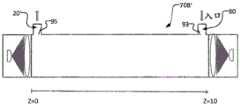
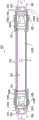
本公开的另一方面是一种用于利用UV辐射来照射流体流的紫外线(UV)反应器,该UV反应器包括:流体管道,该流体管道至少部分地由限定管道的外壁限定,用于容许流体流过其中;第一固态UV发射器(例如紫外线发光二极管或UV-LED);第一辐射聚焦元件,其包括一个或多个第一透镜;第二固态UV发射器;以及包括一个或多个第二透镜的第二辐射聚焦元件。流体管道包括流体入口、流体出口和位于入口与出口之间的纵向延伸的流体流动通道,该流体流动通道在纵向方向上延伸,以容许流体在纵向方向上流过流体流动通道的内孔,并且流体流动通道具有通道中心轴线,该通道中心轴线至少在内孔的纵向中间部分中在纵向方向上延伸通过内孔的横截面的形心。所述一个或多个第一透镜被定位在从第一固态UV发射器发射的第一辐射的辐射路径中,以引导来自第一固态UV发射器的第一辐射沿与流体流的纵向方向大致对向的方向从流体流动通道的出口端入射在于流体流动通道中流动的流体上。所述一个或多个第二透镜被定位在从第二固态UV发射器发射的第二辐射的辐射路径中,以引导来自第二固态UV发射器的第二辐射沿与流体流的纵向方向大致对齐的方向并沿与其相同的方向从流体流动通道的入口端入射在于流体流动通道中流动的流体上。该反应器包括:第一壳体,其用于支承第一固态UV发射器,使得第一固态UV发射器的主光轴至少大致与通道中心轴线同轴,并且其中流体出口的出口孔口——在此处流体出口通向流体流动通道的内孔中——由限定管道的外壁和第一壳体的组合限定;和第二壳体,其用于支承第二固态UV发射器,使得第二固态UV发射器的主光轴至少与通道中心轴线大致同轴,并且其中,流体入口的入口孔口——在此处流体入口通向流体流动通道的内孔——由限定管道的外壁和第二壳体的组合限定。Another aspect of the present disclosure is an ultraviolet (UV) reactor for irradiating a fluid flow with UV radiation, the UV reactor comprising: a fluid conduit defined at least in part by an outer wall defining the conduit for Allowing fluid to flow therethrough; a first solid state UV emitter (such as an ultraviolet light emitting diode or UV-LED); a first radiation focusing element comprising one or more first lenses; a second solid state UV emitter; and comprising one or Second radiation focusing elements of the plurality of second lenses. The fluid conduit includes a fluid inlet, a fluid outlet, and a longitudinally extending fluid flow channel between the inlet and the outlet, the fluid flow channel extending in the longitudinal direction to allow fluid to flow through the inner bore of the fluid flow channel in the longitudinal direction, and the fluid The flow channel has a channel center axis which extends through the centroid of the cross-section of the inner bore in the longitudinal direction at least in the longitudinal middle portion of the inner bore. The one or more first lenses are positioned in the radiation path of the first radiation emitted from the first solid-state UV emitter to direct the first radiation from the first solid-state UV emitter in a direction approximately parallel to the longitudinal direction of the fluid flow. The opposing direction is incident on fluid flowing in the fluid flow channel from the outlet end of the fluid flow channel. The one or more second lenses are positioned in the radiation path of the second radiation emitted from the second solid-state UV emitter to direct the second radiation from the second solid-state UV emitter in a direction approximately parallel to the longitudinal direction of the fluid flow. The aligned directions and in the same direction as are incident on the fluid flowing in the fluid flow channels from the inlet ends of the fluid flow channels. The reactor includes a first housing for supporting a first solid state UV emitter such that a major optical axis of the first solid state UV emitter is at least approximately coaxial with the central axis of the channel, and wherein the outlet orifice of the fluid outlet— - in the bore where the fluid outlet opens into the fluid flow channel - defined by the combination of the outer wall defining the conduit and the first housing; and a second housing for supporting a second solid state UV emitter such that the first The principal optical axis of the two solid state UV emitters is at least approximately coaxial with the central axis of the channel, and wherein the inlet orifice of the fluid inlet - where the fluid inlet leads to the inner bore of the fluid flow channel - is defined by the outer wall of the duct and The combination of the second housing is defined.
UV反应器可包括本文描述的UV反应器的任何特征。The UV reactor can include any of the features of the UV reactors described herein.
本公开的另一方面是一种用于使用紫外线(UV)反应器来利用UV辐射照射行进通过反应器的流体以由此处理流体的方法。该方法包括:提供UV反应器,该UV反应器包括:流体管道,该流体管道至少部分地由限定管道的外壁限定以容许流体流过其中;第一固态UV发射器(例如,紫外线发光二极管或UV-LED);包括一个或多个第一透镜的第一辐射聚焦元件;第二固态UV发射器;以及包括一个或多个第二透镜的第二辐射聚焦元件;经由流体入口将流体引入到纵向延伸的流体流动通道的内孔中;允许流体沿纵向方向流过纵向延伸的流体流动通道;以及经由流体出口从流体流动通道中除去流体,流体出口位于流体流动通道的与入口纵向对置的端部处,其中流体流动通道具有通道中心轴线,该通道中心轴线至少在内孔的纵向中间部分中沿纵向方向延伸通过内孔的横截面的形心;引导来自第一固态UV发射器的第一辐射通过所述一个或多个第一透镜并由此使第一辐射沿与流体流的纵向方向大致相反的方向从流体流动通道的出口端入射在于流体流动通道中流动的流体上;引导来自第二固态UV发射器的第二辐射通过所述一个或多个第二透镜并由此使第二辐射沿与流体流的纵向方向大致对齐的方向并沿与其相同的方向从流体流动通道的入口端入射在于流体流动通道中流动的流体上;将第一固态UV发射器支承在第一壳体中,使得第一固态UV发射器的主光轴至少与通道中心轴线大致同轴,并且其中流体出口的出口孔口——在此处流体出口通向流体流动通道的内孔中——由限定管道的外壁和第一壳体的组合限定;以及将第二固态UV发射器支承在第二壳体中,使得第二固态UV发射器的主光轴至少与通道中心轴线大致同轴,并且其中流体入口的入口孔口——在此处流体入口通向流体流动通道的内孔中——由限定管道的外壁和第二壳体的组合限定。Another aspect of the present disclosure is a method for using an ultraviolet (UV) reactor to irradiate a fluid traveling through the reactor with UV radiation to thereby treat the fluid. The method includes: providing a UV reactor comprising: a fluid conduit at least partially defined by an outer wall defining the conduit to allow fluid to flow therethrough; a first solid state UV emitter (e.g., an ultraviolet light emitting diode or UV-LED); a first radiation focusing element comprising one or more first lenses; a second solid state UV emitter; and a second radiation focusing element comprising one or more second lenses; fluid is introduced into the In the bore of the longitudinally extending fluid flow channel; allowing fluid to flow in a longitudinal direction through the longitudinally extending fluid flow channel; and removing fluid from the fluid flow channel via a fluid outlet located at a longitudinally opposite side of the fluid flow channel from the inlet At the end, wherein the fluid flow channel has a channel central axis extending in the longitudinal direction through the centroid of the cross-section of the inner bore at least in the longitudinal middle portion of the inner bore; guiding the first solid-state UV emitter from the first passing a radiation through the one or more first lenses and thereby causing the first radiation to be incident on the fluid flowing in the fluid flow channel from the outlet end of the fluid flow channel in a direction substantially opposite to the longitudinal direction of the fluid flow; The second radiation of the second solid state UV emitter passes through the one or more second lenses and thereby directs the second radiation from the inlet of the fluid flow channel in a direction substantially aligned with and in the same direction as the longitudinal direction of the fluid flow. end incident on fluid flowing in the fluid flow channel; supporting the first solid state UV emitter in the first housing such that the principal optical axis of the first solid state UV emitter is at least approximately coaxial with the central axis of the channel, and wherein the fluid an outlet orifice for the outlet—where the fluid outlet opens into the bore of the fluid flow channel—defined by the combination of the outer wall defining the conduit and the first housing; and supporting the second solid state UV emitter in the second housing body, such that the principal optical axis of the second solid-state UV emitter is at least substantially coaxial with the central axis of the channel, and wherein the inlet orifice of the fluid inlet—where the fluid inlet opens into the inner bore of the fluid flow channel—by The outer wall defining the duct is defined in combination with the second housing.
该方法可以包括将UV反应器安装在沿第一方向延伸的已有流体流动管道中。将UV反应器安装在现有流体流动管道中可以包括:从现有管道中移除一部分现有管道,以露出现有管道的上游部分和现有管道的下游部分,上游部分和下游部分在第一方向上彼此大致对齐;将UV反应器的流体入口连接到现有管道的上游部分的端部;以及将UV反应器的流体出口连接到现有管道的下游部分的端部。将UV反应器的流体入口连接到现有管道的上游部分的端部并将UV反应器的流体出口连接到现有管道的下游部分的端部可以共同包括使流体流的纵向方向与第一方向对齐。The method may include installing a UV reactor in an existing fluid flow conduit extending in a first direction. Installing the UV reactor in existing fluid flow piping may include removing a portion of the existing piping from the existing piping to expose an upstream portion of the existing piping and a downstream portion of the existing piping, the upstream portion and the downstream portion being in substantially aligned with each other in one direction; connecting the fluid inlet of the UV reactor to the end of the upstream portion of the existing piping; and connecting the fluid outlet of the UV reactor to the end of the downstream portion of the existing piping. Connecting the fluid inlet of the UV reactor to the end of the upstream portion of the existing conduit and connecting the fluid outlet of the UV reactor to the end of the downstream portion of the existing conduit may collectively comprise aligning the longitudinal direction of the fluid flow with the first direction align.
该方法可以包括使用本文描述的UV反应器的任何特征。The method can include using any of the features of the UV reactor described herein.
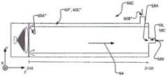
本公开的另一方面是一种用于用UV辐射照射流体流的紫外线(UV)反应器。该反应器包括:流体管道,该流体管道至少部分地由限定管道的外壁限定,以容许流体流过其中;固态UV发射器(例如紫外发光二极管或UV-LED);以及包括一个或多个透镜的辐射聚焦元件。流体管道包括流体入口、流体出口和位于入口与出口之间的纵向延伸的流体流动通道。流体流动通道沿纵向方向延伸,以容许流体沿纵向方向流过流体流动通道的内孔。流体流动通道具有通道中心轴线,该通道中心轴线至少在内孔的纵向中间部分中沿纵向方向延伸通过内孔的横截面的形心。所述一个或多个透镜位于从固态UV发射器发射的辐射的辐射路径中,以引导来自固态UV发射器的辐射入射在于流体流动通道中流动的流体上并由此提供流体流动通道的内孔内的辐射通量率分布。所述一个或多个透镜可以包括被定位成接收来自UV发射器的辐射的半球形透镜和被定位成接收来自半球形透镜的辐射的平凸透镜或菲涅耳透镜。半球形透镜和平凸透镜或菲涅耳透镜的平面侧可以面向UV发射器。固态UV发射器、半球形透镜和平凸透镜或菲涅耳透镜的光轴可以与通道中心轴线平行,并且在一些情况下可以与通道中心轴线同轴。Another aspect of the present disclosure is an ultraviolet (UV) reactor for irradiating a fluid stream with UV radiation. The reactor includes: a fluid conduit at least partially defined by an outer wall defining the conduit to allow fluid to flow therethrough; a solid state UV emitter (such as an ultraviolet light emitting diode or UV-LED); and one or more lenses radiation focusing elements. The fluid conduit includes a fluid inlet, a fluid outlet, and a longitudinally extending fluid flow channel between the inlet and the outlet. The fluid flow channel extends in a longitudinal direction to allow fluid to flow through the bore of the fluid flow channel in the longitudinal direction. The fluid flow channel has a channel center axis extending through the centroid of the cross-section of the inner bore in the longitudinal direction at least in the longitudinal middle portion of the inner bore. The one or more lenses are positioned in the radiation path of the radiation emitted from the solid state UV emitter to direct the radiation from the solid state UV emitter to be incident on the fluid flowing in the fluid flow channel and thereby provide the bore of the fluid flow channel Radiant flux rate distribution in . The one or more lenses may include a hemispherical lens positioned to receive radiation from the UV emitter and a plano-convex or Fresnel lens positioned to receive radiation from the hemispherical lens. The flat side of the hemispherical lens, plano-convex lens or Fresnel lens may face the UV emitter. The optical axis of the solid-state UV emitter, hemispherical lens, plano-convex lens, or Fresnel lens can be parallel to, and in some cases can be coaxial with, the central axis of the channel.
平凸透镜可被定位在离从半球形透镜发射的辐射的焦点小于其固有焦距f1的距离f’处。平凸透镜相对于半球形透镜的焦点的距离/间距f’可以比平凸透镜的固有焦距f1小距离差Δ。距离差Δ可以在平凸透镜的焦距f1的10%-35%的范围内。距离差Δ可以在平凸透镜的焦距f1的15%-30%的范围内。距离差Δ可以在平凸透镜的焦距f1的20%-30%的范围内。The plano-convex lens may be positioned at a distance f' from the focal point of radiation emitted from the hemispherical lens which is less than its intrinsic focal length f1. The distance/spacing f' of the plano-convex lens relative to the focal point of the hemispherical lens can be smaller than the intrinsic focal length f1 of the plano-convex lens by a distance difference Δ. The distance difference Δ may be in the range of 10%-35% of the focal length f1 of the plano-convex lens. The distance difference Δ may be in the range of 15%-30% of the focal length f1 of the plano-convex lens. The distance difference Δ may be in the range of 20%-30% of the focal length f1 of the plano-convex lens.
UV反应器可以包括:第二固态UV发射器,该第二固态UV发射器具有与固态UV发射器的主光轴逆平行地定向的第二/辅助主光轴;和第二辐射聚焦元件,该第二辐射聚焦元件包括一个或多个辅助/第二透镜,所述第二透镜被定位在从第二固态UV发射器发射的辐射的第二辐射路径中,以引导来自第二固态UV发射器的辐射入射在于流体流动通道中流动的流体上并由此提供流体流动通道的内孔内的第二辐射通量率分布。所述一个或多个辅助/第二透镜可以包括被定位成接收来自第二UV发射器的辐射的辅助/第二半球形透镜和被定位成接收来自第二半球形透镜的辐射的辅助/第二平凸透镜。第二半球形透镜和第二平凸透镜两者都可以使其平面侧面向第二UV发射器。第二固态UV发射器、第二半球形透镜和第二平凸透镜的光轴可以与通道中心轴线平行,并且在一些情况下可以与通道中心轴线同轴。辅助/第二平凸透镜可以被定位在离从第二半球形透镜发射的辐射的焦点的距离小于其固有焦距f2的第二距离f2’处。第二平凸透镜相对于辅助/第二半球形透镜的焦点的第二间距/距离f2’可以比第二平凸透镜的固有焦距f2小第二距离差Δ2。第二距离差Δ2可以在辅助/第二平凸透镜的焦距f2的10%-35%的范围内。第二距离差Δ2可以在第二平凸透镜的焦距f2的15%-30%的范围内。第二距离差Δ2可以在第二平凸透镜的焦距f2的20%-30%的范围内。The UV reactor may comprise: a second solid state UV emitter having a second/auxiliary principal optical axis oriented antiparallel to the principal optic axis of the solid state UV emitter; and a second radiation focusing element, The second radiation focusing element includes one or more auxiliary/secondary lenses positioned in the second radiation path of the radiation emitted from the second solid state UV emitter to direct radiation emitted from the second solid state UV emitter. The radiation of the detector is incident on the fluid flowing in the fluid flow channel and thereby provides a second radiant flux rate distribution within the bore of the fluid flow channel. The one or more secondary/secondary lenses may include a secondary/second hemispherical lens positioned to receive radiation from the second UV emitter and a secondary/second hemispherical lens positioned to receive radiation from the second hemispherical lens Two plano-convex lenses. Both the second hemispherical lens and the second plano-convex lens may have their planar sides facing the second UV emitter. The optical axes of the second solid state UV emitter, the second hemispherical lens, and the second plano-convex lens can be parallel to, and in some cases can be coaxial with, the channel central axis. The secondary/second plano-convex lens may be positioned at a second distance f2' from the focal point of radiation emitted from the second hemispherical lens at a distance less than its intrinsic focal length f2. The second spacing/distance f2' of the second plano-convex lens relative to the focal point of the auxiliary/second hemispherical lens may be smaller than the intrinsic focal length f2 of the second plano-convex lens by a second distance difference Δ2. The second distance difference Δ2 may be in the range of 10%-35% of the focal length f2 of the auxiliary/second plano-convex lens. The second distance difference Δ2 may be in the range of 15%-30% of the focal length f2 of the second plano-convex lens. The second distance difference Δ2 may be in the range of 20%-30% of the focal length f2 of the second plano-convex lens.
该UV反应器可包括本文中描述的UV反应器的任何特征。The UV reactor can include any of the features of the UV reactors described herein.
本公开的另一方面是一种使用紫外线(UV)反应器来利用UV辐射照射行进通过反应器的流体以由此处理流体的方法。该方法包括:提供UV反应器,该UV反应器包括:流体管道,该流体管道至少部分地由限定管道的外壁限定,以容许流体流过其中;固态UV发射器(例如,紫外线发光二极管或UV-LED);以及包括一个或多个透镜的辐射聚焦元件;经由流体入口将流体引入到纵向延伸的流体流动通道的内孔中,从而允许流体沿纵向方向流过纵向延伸的流体流动通道,并经由流体出口从流体流动通道中除去流体,流体出口位于流体流动通道的与入口纵向对置的端部处,其中流体流动通道具有通道中心轴线,该通道中心轴线至少在内孔的纵向中间部分中沿纵向方向延伸通过内孔的横截面的形心;引导来自固态UV发射器的辐射通过所述一个或多个透镜并由此使辐射入射在于流体流动通道中流动的流体上,从而提供流体流动通道的内孔内的辐射通量率分布;其中所述一个或多个透镜包括半球形透镜和平凸透镜,并且该方法包括:将半球形透镜定位成接收来自UV发射器的辐射,将平凸透镜定位成接收来自半球形透镜的辐射,使半球形透镜和平凸透镜两者的平面侧都定向为面向UV发射器,以及使固态UV发射器、半球形透镜和平凸透镜的光轴与通道中心轴线平行并且在一些情况下与通道中心轴线同轴。Another aspect of the present disclosure is a method of using an ultraviolet (UV) reactor to treat a fluid traveling through the reactor by irradiating it with UV radiation. The method includes providing a UV reactor comprising: a fluid conduit at least partially defined by an outer wall defining the conduit to allow fluid to flow therethrough; a solid state UV emitter (e.g., an ultraviolet light emitting diode or UV - LED); and a radiation focusing element comprising one or more lenses; introducing fluid into the inner bore of the longitudinally extending fluid flow channel via the fluid inlet, thereby allowing the fluid to flow in a longitudinal direction through the longitudinally extending fluid flow channel, and fluid is removed from the fluid flow channel via a fluid outlet located at an end of the fluid flow channel longitudinally opposite the inlet, wherein the fluid flow channel has a channel center axis at least in a longitudinally central portion of the inner bore extending in the longitudinal direction through the centroid of the cross-section of the bore; directing radiation from the solid state UV emitter through the one or more lenses and thereby making the radiation incident on the fluid flowing in the fluid flow channel, thereby providing fluid flow A radiant flux rate distribution within the bore of the channel; wherein the one or more lenses comprise a hemispherical lens and a plano-convex lens, and the method comprises: positioning the hemispherical lens to receive radiation from the UV emitter, positioning the plano-convex lens To receive radiation from the hemispherical lens, with the planar sides of both the hemispherical lens and the plano-convex lens oriented to face the UV emitter, and with the optical axes of the solid-state UV emitter, the hemispherical lens and the plano-convex lens parallel to the central axis of the channel and in In some cases coaxial with the channel central axis.
该方法可以包括使用本文描述的UV反应器的任何特征。The method can include using any of the features of the UV reactor described herein.
本公开的另一方面是一种用于通过将本文中的任何其它权利要求的UV反应器安装在沿第一方向延伸的现有流体流动管道中来使用该UV反应器的方法。将UV反应器安装在现有流体流动管道中包括:从现有管道中移除一部分现有管道,以露出现有管道的上游部分和现有管道的下游部分,该上游部分和下游部分在第一方向上彼此大致对齐;将UV反应器的流体入口连接到现有管道的上游部分的端部;以及将UV反应器的流体出口连接到现有管道的下游部分的端部;其中将UV反应器的流体入口连接到现有管道的上游部分的端部并将UV反应器的流体出口连接到现有管道的下游部分的端部共同包括将流体流的纵向方向与第一方向对齐。Another aspect of the present disclosure is a method for using the UV reactor of any other claim herein by installing the UV reactor in an existing fluid flow conduit extending in a first direction. Installing a UV reactor in an existing fluid flow pipeline includes removing a portion of the existing pipeline from the existing pipeline to expose an upstream portion of the existing pipeline and a downstream portion of the existing pipeline, the upstream and downstream portions being in roughly aligned with each other in one direction; connecting the fluid inlet of the UV reactor to the end of the upstream portion of the existing pipeline; and connecting the fluid outlet of the UV reactor to the end of the downstream portion of the existing pipeline; wherein the UV reaction Connecting the fluid inlet of the UV reactor to the end of the upstream portion of the existing pipeline and connecting the fluid outlet of the UV reactor to the end of the downstream portion of the existing pipeline together comprise aligning the longitudinal direction of the fluid flow with the first direction.
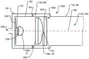
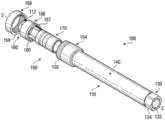
本公开的另一方面是一种流体处理设备,该流体处理设备包括:主体,该主体沿着流动路径在第一端部和沿着流动路径与第一端部对置的第二端部之间延伸,第一端部包括沿着流动路径的入口,第二端部包括沿着流动路径的出口;流动通道,该流动通道在主体内沿着流动路径延伸,以将流体从入口引导到出口;和固态辐射源,该固态辐射源可安装在流动通道的空腔中以沿着流动路径将辐射发射到流动通道中,该固态辐射源包括导热部分,该导热部分被定位成当流体在从入口流向出口并且固态辐射源安装在空腔中时与流体接触。Another aspect of the present disclosure is a fluid treatment device comprising a body between a first end along a flow path and a second end opposite the first end along the flow path extending between the first end portion including an inlet along the flow path, the second end portion including an outlet along the flow path; a flow channel extending within the body along the flow path to guide fluid from the inlet to the outlet and a solid-state radiation source mountable in the cavity of the flow channel to emit radiation into the flow channel along the flow path, the solid-state radiation source comprising a thermally conductive portion positioned so that when the fluid is flowing from The inlet flows to the outlet and the solid state radiation source is in contact with the fluid when installed in the cavity.
固态辐射源可以包括固态UV发射器。该设备还可包括一个或多个可定位成折射来自固态辐射源的辐射的透镜。例如,所述一个或多个透镜可以构造成使流动通道中的一个位置处的辐射强度与当流体正在从入口流向出口并且固态辐射源安装在空腔中时、在流动通道中的该位置处的流体的速率关联。空腔可以由流动通道的内表面限定,所述内表面构造成当流体正在从入口流向出口并且固态辐射源安装在空腔中时使流体围绕固态辐射源流动并与固态辐射源的导热部分接触。例如,空腔的内表面可以与固态辐射源的外表面接合,以在流体正在从入口流向出口并且固态辐射源安装在空腔中时保持固态辐射源相对于流动通道的位置。Solid state radiation sources may include solid state UV emitters. The device may also include one or more lenses positionable to refract radiation from the solid state radiation source. For example, the one or more lenses may be configured to compare the radiation intensity at a location in the flow channel to that position in the flow channel when the fluid is flowing from the inlet to the outlet and the solid state radiation source is mounted in the cavity. The velocity correlation of the fluid. The cavity may be defined by an inner surface of the flow channel configured to allow the fluid to flow around the solid state radiation source and contact the thermally conductive portion of the solid state radiation source when the fluid is flowing from the inlet to the outlet and the solid state radiation source is installed in the cavity . For example, the inner surface of the cavity may engage the outer surface of the solid state radiation source to maintain the position of the solid state radiation source relative to the flow channel when fluid is flowing from the inlet to the outlet and the solid state radiation source is mounted in the cavity.
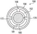
该设备还可包括安装结构,该安装结构在空腔的内表面与光学单元的外表面之间延伸以维持固态辐射源的位置。例如,安装结构可以沿着流动路径延伸,并且包括多个部分,所述多个部分围绕流动路径在周向上间隔开,以限定沿着流动路径延伸并在固态辐射源位于空腔中时与导热部分接触的多个流动通道。每个流动路径可以改变流过其中的流体的速率。在一些方面,固态辐射源的外表面可以包括固态辐射源的导热部分的外表面;并且当固态辐射源位于空腔中时,安装结构可以不延伸到固态辐射源的导热部分,以在流体从入口流向出口时,防止固态辐射源的导热部分、主体和流体之间的热传递。或者,固态辐射源的外表面可以包括固态辐射源的导热部分的外表面;并且安装结构可以延伸到导热部分的外表面,以在流体从入口流向出口时,容许固态辐射源的导热部分、主体和流体之间的热传递。例如,安装结构、空腔的内表面和/或固态辐射源的导热部分中的一者或多者可以包含金属材料。The apparatus may also include a mounting structure extending between the inner surface of the cavity and the outer surface of the optical unit to maintain the position of the solid state radiation source. For example, the mounting structure may extend along the flow path and include a plurality of portions spaced circumferentially about the flow path to define a thermally conductive surface extending along the flow path and compatible with heat conduction when the solid state radiation source is located in the cavity. Multiple flow channels in partial contact. Each flow path can vary the rate of fluid flowing through it. In some aspects, the exterior surface of the solid state radiation source may comprise the exterior surface of the thermally conductive portion of the solid state radiation source; and when the solid state radiation source is located in the cavity, the mounting structure may not extend to the thermally conductive portion of the solid state radiation source to allow for fluid flow from the Prevents heat transfer between the thermally conductive portion of the solid state radiation source, the body, and the fluid as the inlet flows to the outlet. Alternatively, the outer surface of the solid state radiation source may comprise the outer surface of the thermally conductive portion of the solid state radiation source; and the mounting structure may extend to the outer surface of the thermally conductive portion to allow the thermally conductive portion, body, and heat transfer between fluids. For example, one or more of the mounting structure, the interior surface of the cavity, and/or the thermally conductive portion of the solid state radiation source may comprise a metallic material.
在一些方面,固态辐射源可以被容纳在光学单元中,该光学单元包括导热部分和一个或多个透镜,所述一个或多个透镜可定位成折射来自固态辐射源的辐射,和/或光学单元可以可拆卸地安装在空腔中。例如,该设备还可包括安装结构,该安装结构在空腔的内表面与光学单元的外表面之间延伸,以在流体正在从入口流向出口并且光学单元安装在空腔中时保持光学单元相对于流动通道的位置。当将光学单元安装在空腔中时,光学单元的导热部分可以与空腔的内表面间隔开。例如,主体可以包括套接机构,并且套接机构可以包括:第一端部部分;第二端部部分;和联接器,该联接器可与第一端部部分和第二端部部分接合以限定空腔。当环与套接机构接合时,光学单元可以可拆卸地定位在空腔中。例如,光学单元可以可拆卸地安装和/或定位在套接机构的第二端部部分中和/或入口和出口可以与管成一直线安装。In some aspects, the solid state radiation source can be housed in an optical unit that includes a thermally conductive portion and one or more lenses that can be positioned to refract radiation from the solid state radiation source, and/or optically The unit can be removably mounted in the cavity. For example, the device may also include mounting structure extending between the inner surface of the cavity and the outer surface of the optical unit to hold the optical unit relative to each other when the fluid is flowing from the inlet to the outlet and the optical unit is mounted in the cavity. position in the flow channel. When the optical unit is mounted in the cavity, the thermally conductive portion of the optical unit may be spaced apart from an inner surface of the cavity. For example, the body may include a socket mechanism, and the socket mechanism may include: a first end portion; a second end portion; and a coupler engageable with the first end portion and the second end portion to Define the cavity. The optical unit may be removably positioned in the cavity when the ring is engaged with the socket mechanism. For example, the optical unit may be removably mounted and/or positioned in the second end portion of the socket mechanism and/or the inlet and outlet may be mounted in line with the tube.
在一些方面,空腔可以是第一空腔,固态辐射源可以是第一固态辐射源,辐射可以是第一辐射,流动通道可以限定第二空腔,并且该设备还可包括:第二固态辐射源,该第二固态辐射源可安装在第二空腔中以沿着流动路径向流动通道中发射第二辐射,该第二固态辐射源包括定位成当流体正在从入口流向出口并且第二固态辐射源安装在第二空腔中时与流体接触的导热部分。在一些方面,第一固态辐射源被安装在第一空腔中,并且第二固态辐射源定位在第二空腔中,第一固态辐射源被定位成在第一方向上沿着流动路径发射第一辐射,第二固态辐射源被定位成在第二方向上沿着流动路径发射第二辐射,并且第一方向不同于第二方向。In some aspects, the cavity can be a first cavity, the solid state radiation source can be a first solid state radiation source, the radiation can be a first radiation, the flow channel can define a second cavity, and the device can further include: a second solid state radiation source a radiation source, the second solid state radiation source mountable in the second cavity to emit a second radiation along the flow path into the flow channel, the second solid state radiation source comprising a second solid state radiation source positioned so that when the fluid is flowing from the inlet to the outlet and the second The thermally conductive portion of the solid state radiation source that is in contact with the fluid when installed in the second cavity. In some aspects, a first solid state radiation source is mounted in the first cavity and a second solid state radiation source is positioned in the second cavity, the first solid state radiation source being positioned to emit along the flow path in a first direction The first radiation, the second solid state radiation source are positioned to emit the second radiation in a second direction along the flow path, and the first direction is different from the second direction.
在一些方面,所述一个或多个透镜可包括:会聚透镜,该会聚透镜被定位成接收来自固态辐射源的辐射;以及准直透镜,该准直透镜被定位成接收由会聚透镜折射的辐射。例如,准直透镜可以被定位在离由会聚透镜折射的辐射的焦点的距离小于其焦距的距离处。例如,准直透镜离由会聚透镜折射的辐射的焦点的距离与准直透镜的焦距之差可以近似等于准直透镜的焦距的10%-35%。作为又一示例,准直透镜相对于焦点的位置f’与准直透镜相对于焦点的焦距f1之间的距离差Δ=f-f’可以在焦距f1的10%-35%的范围内。In some aspects, the one or more lenses may include: a converging lens positioned to receive radiation from the solid state radiation source; and a collimating lens positioned to receive radiation refracted by the converging lens . For example, the collimating lens may be positioned at a distance from the focal point of radiation refracted by the converging lens that is less than its focal length. For example, the difference between the distance of the collimating lens from the focal point of the radiation refracted by the converging lens and the focal length of the collimating lens may be approximately equal to 10%-35% of the focal length of the collimating lens. As yet another example, the distance difference Δ=f-f' between the position f' of the collimator lens relative to the focal point and the focal length f1 of the collimator lens relative to the focal point may be in the range of 10%-35% of the focal length f1.
在另一些示例中,会聚透镜可以与固态辐射源一体化。所述一个或多个透镜包括至少具有局部的凸面透镜的透镜、穹顶透镜、平凸透镜和菲涅耳透镜中的一者或或者。作为又一示例,固态辐射源包括多个固态辐射源,并且导热部分对于多个固态辐射源而言是公共的或各自单独的。In other examples, the converging lens can be integrated with the solid state radiation source. The one or more lenses include one or either of a lens having at least a partially convex lens, a dome lens, a plano-convex lens, and a Fresnel lens. As yet another example, the solid-state radiation source includes a plurality of solid-state radiation sources, and the thermally conductive portion is common to or separate from each of the plurality of solid-state radiation sources.
本公开的另一方面是一种方法,该方法包括:引导来自入口的流体通过反应器的沿着流动轴线延伸的流动通道;使流体暴露于从光学单元发射到流动通道中的UV辐射,该光学单元位于流动通道的空腔中,该空腔包括用于发射UV辐射的固态辐射源和与固态辐射源热耦合的至少一个导热部分;使流体至少部分地围绕光学单元流到出口,以使得光学单元的至少一个导热部分与流体热耦合;并用流体冷却光学单元。Another aspect of the present disclosure is a method comprising: directing fluid from an inlet through a flow channel of a reactor extending along a flow axis; exposing the fluid to UV radiation emitted from an optical unit into the flow channel, the The optical unit is positioned in a cavity of the flow channel, the cavity including a solid state radiation source for emitting UV radiation and at least one thermally conductive portion thermally coupled to the solid state radiation source; the fluid flows at least partially around the optical unit to the outlet such that At least one thermally conductive portion of the optical unit is thermally coupled to the fluid; and the fluid is used to cool the optical unit.
该方法可以包括使固态辐射源发射UV辐射,并且其中,固态辐射源是固态UV发射器;和/或用光学单元中的至少一个透镜折射发射的UV辐射。例如,折射UV辐射可包括使UV辐射穿过光学单元中的至少一个透镜,该至少一个透镜构造成使流动通道中的一个位置处的辐射强度与流动通道中的该位置处的流体的速率相匹配。冷却光学单元可以包括将热量从光学单元经光学单元的至少一个导热部分传递到与表面热接触的流体。例如,反应器可以至少部分地由导热材料构成,并且冷却光学单元可以包括通过与导热部分热耦合的安装结构将热量从光学单元经光学单元的导热部分传递到反应器,所述安装结构由导热材料构成。The method may comprise causing a solid state radiation source to emit UV radiation, and wherein the solid state radiation source is a solid state UV emitter; and/or refracting the emitted UV radiation with at least one lens in the optical unit. For example, refracting UV radiation can include passing UV radiation through at least one lens in an optical unit configured to match the intensity of the radiation at a location in the flow channel to the velocity of the fluid at that location in the flow channel. match. Cooling the optical unit may include transferring heat from the optical unit to a fluid in thermal contact with the surface via at least one thermally conductive portion of the optical unit. For example, the reactor can be constructed at least in part of a thermally conductive material, and cooling the optical unit can include transferring heat from the optical unit to the reactor via the thermally conductive portion of the optical unit via a mounting structure thermally coupled to the thermally conductive portion, the mounting structure being thermally coupled to the reactor. Material composition.
在一些方面,反应器可以由非导热材料构成,并且冷却光学单元仅包括将来自光学单元的热量经光学单元的至少一个导热部分传递到与表面热接触的流体。使流体至少部分地围绕光学单元流动可以包括使流体围绕光学单元的表面流动。该方法可以进一步包括:使流体以与从光学单元发射的UV辐射的强度正相关的速率流动。例如,使流体至少部分地围绕光学单元流动可以包括使流体至少部分地围绕可拆卸的光学单元流动和/或使流体至少部分地围绕整体式光学单元流动。In some aspects, the reactor can be constructed of a thermally non-conductive material, and cooling the optical unit simply includes transferring heat from the optical unit via at least one thermally conductive portion of the optical unit to a fluid in thermal contact with the surface. Flowing the fluid at least partially around the optical unit may comprise flowing the fluid around a surface of the optical unit. The method may further comprise flowing the fluid at a rate that is positively related to the intensity of the UV radiation emitted from the optical unit. For example, flowing fluid at least partially around the optical unit may include flowing fluid at least partially around a detachable optical unit and/or flowing fluid at least partially around a monolithic optical unit.
作为又一示例,该方法可以进一步包括:在引导流体通过流动通道之前从附接到入口上的与流动轴线同轴的第一管接收流体;以及在用流体冷却光学单元之后,将流体输送到附接到出口上的与流动轴线同轴的第二管。例如,光学单元可以是第一光学单元,并且该方法可以进一步包括:使流体从入口至少部分地围绕第二光学单元流动,第二光学单元包括至少一个导热部分,使得第二光学单元的所述至少一个导热部分在引导流体通过流动通道之前与流体热耦合;使流体暴露于从第二光学单元发射到流动通道中的UV辐射,第二光学单元包括用于发射UV辐射的第二固态辐射源,第二固态辐射源与第二光学单元的所述至少一个导热部分热耦合;以及用流体冷却第二光学单元。As yet another example, the method may further include: receiving fluid from a first tube attached to the inlet coaxial with the flow axis prior to directing the fluid through the flow channel; and delivering the fluid to the A second tube coaxial with the flow axis is attached to the outlet. For example, the optical unit may be a first optical unit, and the method may further comprise: flowing fluid from an inlet at least partially around a second optical unit, the second optical unit including at least one thermally conductive portion such that the second optical unit at least one thermally conductive portion is thermally coupled to the fluid prior to directing the fluid through the flow channel; exposing the fluid to UV radiation emitted into the flow channel from a second optical unit comprising a second solid state radiation source for emitting UV radiation , a second solid state radiation source thermally coupled to the at least one thermally conductive portion of the second optical unit; and cooling the second optical unit with a fluid.
本公开的另一方面是一种光学单元,该光学单元包括:包括空腔的壳体;以及PCB,该PCB在空腔的第一端部处附接到壳体的第一端部上;空腔中的固态辐射源,该固态辐射源附接到PCB上并与PCB的导热部分热耦合;空腔中的第一透镜,该第一透镜被定位成与固态辐射源相邻,以折射由固态辐射源发射的辐射;空腔中的第二透镜,其与第一透镜间隔开,并且被定位成折射由固态辐射源发射并由第一透镜折射的辐射;和透UV部件,该透UV部件在空腔的第二端处附接到壳体的第二端部上。Another aspect of the present disclosure is an optical unit comprising: a housing including a cavity; and a PCB attached to the first end of the housing at the first end of the cavity; a solid state radiation source in a cavity attached to the PCB and thermally coupled to a thermally conductive portion of the PCB; a first lens in the cavity positioned adjacent to the solid state radiation source to refract Radiation emitted by the solid-state radiation source; a second lens in the cavity spaced apart from the first lens and positioned to refract the radiation emitted by the solid-state radiation source and refracted by the first lens; and a UV-transmissive component that transmits The UV component is attached to the second end of the housing at the second end of the cavity.
在一些方面,光学单元可以可拆卸地安装在流体管道的空腔中,使得在流体管道中流动的流体围绕该单元流动。例如,在流体管道中流动的流体可以围绕光学单元流动并与光学单元的壳体的外表面的至少一个导热部分热耦合。光学单元通过从与光学单元的外表面接合的、空腔的内表面延伸的一个或多个结构可拆卸地安装到流体管道的空腔上。例如,光学单元的外表面可以由光学单元的非导热部分的外表面限定,并且所述一个或多个结构延伸到非导热部分的外表面,防止光学单元的导热部分与主体之间的热传递,并且允许导热部分与流体之间的热传递。作为又一示例,固态辐射源可以包括多个固态辐射源,并且导热部分对于多个固态辐射源可以是公共的或各自单独的。In some aspects, the optical unit can be removably mounted in the cavity of the fluid conduit such that fluid flowing in the fluid conduit flows around the unit. For example, a fluid flowing in the fluid conduit may flow around the optical unit and be thermally coupled with at least one thermally conductive portion of the outer surface of the housing of the optical unit. The optical unit is removably mounted to the cavity of the fluid conduit by one or more structures extending from the inner surface of the cavity engaging the outer surface of the optical unit. For example, the outer surface of the optical unit may be defined by the outer surface of the thermally non-conductive portion of the optical unit, and the one or more structures extend to the outer surface of the non-thermally conductive portion, preventing heat transfer between the thermally conductive portion of the optical unit and the body , and allow heat transfer between the heat conducting part and the fluid. As yet another example, the solid state radiation source may include multiple solid state radiation sources, and the thermally conductive portion may be common to or each separate from the multiple solid state radiation sources.
除了上述示例性方面之外,通过参考附图并研究以下详细描述,其它方面将变得显而易见。In addition to the exemplary aspects described above, further aspects will become apparent by reference to the drawings and by study of the following detailed description.
附图说明Description of drawings
示例性实施方式在附图的参考图中示出。本文公开的实施方式和附图旨在被认为是说明性的而不是限制性的。Exemplary embodiments are shown in the reference figures of the drawings. The embodiments and drawings disclosed herein are intended to be considered as illustrative rather than restrictive.
图1A-1D示出了根据特定示例性实施例的UV反应器的截面图。1A-1D illustrate cross-sectional views of UV reactors according to certain exemplary embodiments.
图2A、2B和2C示出了图1A的反应器的流体流动通道的内孔的截面的辐射通量率分布。图2D示出了图1A的反应器的整个纵向方向的辐射通量图。Figures 2A, 2B and 2C show the radiant flux rate distribution for a cross-section of the inner bore of the fluid flow channel of the reactor of Figure 1A. Fig. 2D shows a radiation flux diagram for the entire longitudinal direction of the reactor of Fig. 1A.
图3A-3D示出了根据特定示例性实施例的UV反应器的截面图。3A-3D illustrate cross-sectional views of UV reactors according to certain exemplary embodiments.
图4A-4C示出了图1A的反应器的流体速率分布的各种模拟图。4A-4C show various simulations of fluid velocity profiles for the reactor of FIG. 1A.
图5A-5C示出了图1B的反应器的流体速率分布的各种模拟图。Figures 5A-5C show various simulations of fluid velocity profiles for the reactor of Figure IB.
图6A-6C示出了图1C的反应器的流体速率分布的各种模拟图。Figures 6A-6C show various simulations of fluid velocity profiles for the reactor of Figure 1C.
图7A和7B示出了根据特定示例性实施例的UV反应器的截面图。7A and 7B show cross-sectional views of UV reactors according to certain exemplary embodiments.
图8A-8C针对具有特定长度的特定流体流动通道示出了图7A的反应器的流体流动通道的内孔的横截面的辐射通量率分布。8A-8C illustrate radiant flux rate distributions for a cross-section of an inner bore of a fluid flow channel of the reactor of FIG. 7A for a specific fluid flow channel of a specific length.
图9A-9D针对具有特定长度的特定流体流动通道示出了图7A的反应器的流体流动通道的内孔的横截面的辐射通量率分布。9A-9D illustrate the radiant flux rate distribution for a cross-section of an inner bore of a fluid flow channel of the reactor of FIG. 7A for a particular fluid flow channel of a particular length.
图10A-10D示出了图7A的反应器的流体速率分布的各种图示。10A-10D show various representations of fluid velocity profiles for the reactor of FIG. 7A.
图11A-11C示出了根据特定实施例的结合了流动调节器的多个示例性反应器。11A-11C illustrate various exemplary reactors incorporating flow regulators, according to certain embodiments.
图12A是根据特定实施例的图1A的反应器的一端的示意图,示出了其壳体、固态UV发射器和透镜。图12B是描绘了根据一特定实施例定位的透镜的特性的示意图。12A is a schematic diagram of one end of the reactor of FIG. 1A showing its housing, solid state UV emitters, and lenses, according to certain embodiments. Figure 12B is a schematic diagram depicting the characteristics of a lens positioned according to a particular embodiment.
图13示出了UV反应器的示例性实施例。Figure 13 shows an exemplary embodiment of a UV reactor.
图14示出了图13的UV反应器的分解图。FIG. 14 shows an exploded view of the UV reactor of FIG. 13 .
图15示出了沿着图13所示的截面线A-A截取的图13的UV反应器的详细截面。FIG. 15 shows a detailed cross-section of the UV reactor of FIG. 13 taken along the section line A-A shown in FIG. 13 .
图16示出了示例性光学单元的详细截面。Figure 16 shows a detailed cross-section of an exemplary optical unit.
图17示出了沿着图15所示的剖面线B-B截取的图13的UV反应器的截面。FIG. 17 shows a section of the UV reactor of FIG. 13 taken along the section line B-B shown in FIG. 15 .
图18示出了另一UV反应器的示例性实施例。Figure 18 shows another exemplary embodiment of a UV reactor.
图19示出了示例性消毒方法。Figure 19 illustrates an exemplary disinfection method.
图20示出了UV反应器的另一示例性实施例。Figure 20 shows another exemplary embodiment of a UV reactor.
具体实施方式Detailed ways
在全部以下描述中,阐述了具体细节以便为本领域技术人员提供更透彻的理解。然而,可能未详细示出或描述众所周知的元件以避免不必要地使本公开模糊。因此,说明书和附图应被视为是在说明的意义上而不是在限制的意义上。Throughout the following description, specific details are set forth in order to provide a thorough understanding to those skilled in the art. However, well known elements may not have been shown or described in detail to avoid unnecessarily obscuring the disclosure. Accordingly, the specification and drawings are to be regarded in an illustrative rather than a restrictive sense.
本公开的实施例针对于通过控制流体和光学环境两者来提供增强的剂量均匀性的UV-LED反应器的实施例。参考特定的辐射源、流体和辐射类型描述一些实施例。例如,辐射源可以是诸如UV-LED的固态辐射源,流体可以是水,并且辐射可以包括UV辐射。除非要求保护,否则提供这些示例是为了方便,而不是要限制本公开。因此,本公开中描述的任何结构实施例可以与任何类似的辐射源、流体和/或辐射类型一起使用。Embodiments of the present disclosure are directed to embodiments of UV-LED reactors that provide enhanced dose uniformity by controlling both the fluidic and optical environments. Some embodiments are described with reference to particular radiation sources, fluids, and radiation types. For example, the radiation source may be a solid state radiation source such as a UV-LED, the fluid may be water, and the radiation may include UV radiation. These examples are provided for convenience and are not intended to limit the disclosure unless claimed. Accordingly, any of the structural embodiments described in this disclosure may be used with any similar radiation source, fluid, and/or radiation type.
在此描述了许多轴线,包括示例性的Z轴。无论在何处使用,用语“横向”是指:躺卧或横穿;横向设置;或与Z轴成直角并且包括垂直和非垂直的布置。用语“纵向”可以用来描述相对的部件和特征结构。例如,纵向可以指的是沿Z轴的第一尺寸或长度长于沿Z轴的第二尺寸或宽度的物体。提供这些用语是为了方便,而不是限制本公开,除非要求保护。A number of axes are described herein, including an exemplary Z-axis. Wherever used, the term "transverse" means: recumbent or transverse; a lateral arrangement; or at right angles to the Z-axis and includes vertical and non-perpendicular arrangements. The term "longitudinal" may be used to describe relative components and features. For example, longitudinal may refer to an object that has a first dimension or length along the Z-axis that is longer than a second dimension or width along the Z-axis. These terms are provided for convenience and not to limit the disclosure unless claimed.
如本文中所使用的,用语“包括”、“包含”或其任何其它变型旨在涵盖非排他性的包含,使得包括元件列表的设备、方法或其元件不仅包括这些元件,而是可以包括未明确列出或设备或方法固有的其它元件。除非另有说明,否则用语“示例性”在“示例”的意义上而非“理想”的意义上使用。在本公开中可以使用各种近似术语,包括“近似地”和“一般地”。近似地是指在述及数的±10%以内。As used herein, the words "comprises," "comprises," or any other variation thereof are intended to cover a non-exclusive inclusion such that an apparatus, method, or element thereof that includes a list of elements includes not only those elements, but may also include an unspecified other elements listed or inherent to the apparatus or method. Unless stated otherwise, the term "exemplary" is used in the sense of "example" rather than "ideal". Various approximating terms may be used in this disclosure, including "approximately" and "generally." Approximately means within ±10% of the stated number.
图1A是根据一个特定实施例的示例性UV反应器10A的截面图。反应器10A可包括至少部分地由限定管道的外壁13限定以容许流体流通过其中的流体管道12、固态紫外线(UV)发射器14(例如,UV-LED)以及包括一个或多个透镜16A的辐射聚焦元件16。除了光学部件(例如,UV发射器14和透镜16A)之外,反应器10A可以由不锈钢、合适的聚合物、塑料、玻璃、石英、这些材料的组合和/或其它合适的材料制成。如图所示,流体管道12可包括流体入口18、流体出口20以及位于入口18与出口20之间的纵向延伸的流体流动通道22。FIG. 1A is a cross-sectional view of an
在图示的实施例中,纵向方向被示为与Z轴对齐;并且流体可以大致沿由箭头24所示的纵向方向流过流体流动通道22。例如,流体可以沿纵向方向24流过流体流动通道22的内孔22A;并且流体流动通道22可具有通道中心轴线30,该通道中心轴线30至少在内孔22A的纵向中间部分22B中沿纵向方向24延伸通过内孔22A的横截面的形心。流体入口18可以包括:一个或多个入口孔口18A,其中流体入口18通向流体流动通道22;一个或多个连接孔口18B,UV反应器10A可经由其连接到向反应器10A提供流体的外部流体系统(未示出);和一个或多个入口管道18C,其可以在入口孔口18A与连接孔口18B之间延伸。类似地,流体出口20可以包括:一个或多个入口孔口20A,在此处流体出口20通向流体流动通道22中;一个或多个连接孔口20B,UV反应器10A可经由其连接到从反应器10A向其提供流体的外部输出流体系统(未示出);和一个或多个出口管道28C,其可以在出口孔口20A与连接孔口20B之间延伸。In the illustrated embodiment, the longitudinal direction is shown aligned with the Z-axis; and fluid may flow through fluid flow channel 22 generally in the longitudinal direction shown by
透镜16A可以位于从紫外线(UV)发射器14发射的辐射26的辐射路径中,以引导来自UV发射器14的辐射26入射在于流体流动通道22中流动的流体上并由此在由限定内孔的表面28限定的流体流动通道22的内孔22A内提供辐射通量率分布(图1A中未示出)。
透镜16A可以构造成提供辐射通量率分布,其中,对于流体流动通道22的内孔22A的相对靠近UV发射器14(例如,在所示的视图中相对接近Z=0)的位置处的横截面而言,辐射通量率分布在离流体流动通道22的内孔22A的通道中心轴线30相对远的位置处相对高,而在较靠近通道中心轴线30的位置处则相对低。通道中心轴线30可包括流体流动通道22的内孔22A或至少流体流动通道22的内孔22A的纵向中间部分22B的中心轴线(例如,圆柱对称轴线)。透镜16A可以进一步构造成提供辐射通量率分布,其中对于流体流动通道22的内孔22A的相对远离UV发射器14(例如,在所示视图中相对接近Z=10)的位置处的横截面而言,辐射通量率分布在离通道中心轴线30相对远的位置处相对低,而在较靠近通道中心轴线30的位置处相对高。
辐射通量率分布的示例性特性在图2A-2D中示出。图2A-2C针对图1A的反应器10A的流体流动通道22的内孔22A在沿着通道中心轴线30的不同位置(例如,在不同的Z值处)的各个横截面示出了辐射通量率分布。图2D示出了用代表较高通量率的较亮区域和代表较低通量率的较暗区域渲染图1A的反应器10A的流体流动通道22的整个纵向方向上的通量率分布。图2A-2C的图示的Y轴代表辐射通量率(以mW/cm2为单位)。图2A-2C的图示的X轴表示离通道中心轴线30的径向距离(例如,在内孔22A的横截面为圆形的情况下,沿着图1A所示的X轴或沿着任何其它合适的径向方向)。图2A-2C的图示的X轴的原点表示通道中心轴线30上的位置;而图2A-2C的图示上的较大的X值表示相对远离通道中心轴线30的位置。Exemplary properties of radiant flux rate distributions are shown in Figures 2A-2D. 2A-2C illustrate the radiant flux for various cross-sections of the inner bore 22A of the fluid flow channel 22 of the
图2A针对相对靠近UV发射器14处的横截面(Z=0,Z=1,Z=2)示出了通量率分布。从图2A中可以看出,对于这些横截面中的每个横截面,通量率在离通道中心轴线30相对远的位置处相对高,而在通道中心轴线30处的相对低。例如,图2B针对离UV发射器14相对远的横截面(Z=6,7,8,9,10)示出了通量率分布。从图2B可以看出,对于这些横截面中的每个横截面,通量率在离通道中心轴线30相对远(例如|x|>2)的位置处相对低,而在较靠近通道中心轴线30(例如|x|<2)的位置处则相对高。对于与Z=9和Z=10对应的图2B的图示,通量率在离通道中心轴线30相对远的所有位置处都较低,而在通道中心轴线30处相对高。图2C针对位置居中的横截面(Z=3,Z=4,Z=5)示出了通量率分布,并且示出了即使在这些中间的横截面中,内孔22A的横截面也设置有相对高的通量率。图2D示出了用代表较高通量率(较高辐照度)的较亮区域和代表较低通量率(较低辐照度)的较暗区域渲染图1A的反应器10A的流体流动通道22的整个纵向方向上的通量率分布。FIG. 2A shows the flux rate distribution for a cross-section relatively close to the UV emitter 14 (Z=0, Z=1, Z=2). As can be seen in FIG. 2A , for each of these cross-sections, the flux rate is relatively high at locations relatively far from the channel
透镜16A可以构造成通过以下中的一者或多者来提供具有上述特征的通量率分布:从多种透镜类型中选择一个或多个透镜;所述一个或多个透镜的形状,例如透镜的厚度和/或透镜的光学表面的曲率;所述一个或多个透镜的位置;以及所述一个或多个透镜的折射率,以提供具有这些特征的辐射通量率分布。辐射聚焦元件16可包括聚焦透镜16A或贴近UV发射器14设置的两个或更多个聚焦透镜16A的组合。聚焦透镜16A可包括会聚透镜、发散透镜和任何其它类型的透镜的任何组合。在一些实施例中,聚焦透镜16A可包括光学上邻近UV发射器14的会聚透镜和与会聚透镜相距某个合适距离的准直透镜。在一些实施例中,透镜16A可以包括会聚透镜和准直透镜,该会聚透镜被定位成接收来自UV发射器14的辐射26,其中该准直透镜可以被定位在离从会聚透镜发出的辐射的焦点小于其焦距(例如,小了距离差Δ)的距离处。
在一些实施例中,透镜16A可以包括半球形透镜和平凸透镜。图12A是根据特定实施例的反应器10A的一端的示意图,其更详细地示出了壳体32、固态UV发射器14和透镜16A。如图12A所示,例如,固态UV发射器14可以与用以向UV发射器14供电的合适的电子器件(未示出)一起安装在电路板14A上。在本例中,透镜16A可以包括:半球形透镜17,其成形和/或定位成接收来自UV发射器14的辐射;和平凸透镜19,其成形和/或定位成接收来自半球形透镜17的辐射。两个透镜17、19各自的平面侧17A,19A可以面向UV发射器14;并且两个透镜17和19的光轴可以与通道中心轴线30同轴,如图12A所示。In some embodiments,
在一些实施例中,在平凸透镜19与流体流动通道22的内孔22A中(例如,壳体32内)的流体之间存在气隙21。在一些实施例中,在平凸透镜19与流体流动通道22的内孔22A中的流体之间存在气隙21和透UV(例如石英)窗口32A。在一些实施例中,平凸透镜19可以定位在离从半球形透镜17发射的辐射的焦点23小于其焦距f1的距离f’处。这在特定实施例的图12B中被示意性地示出,其中从半球形透镜17发出的辐射具有焦点23,并且平凸透镜19具有固有焦距f1,但平凸透镜19不位于离焦点23的距离f1处。作为替代,在图示的实施例中,平凸透镜19位于离焦点23的距离f’处,其中f’比f1小了距离差Δ。在一些实施例中,该距离差Δ在平凸透镜19的焦距f1的10%-35%的范围内。在一些实施例中,该距离差Δ在平凸透镜19的焦距f1的15%-30%的范围内。在一些实施例中,该距离差Δ在平凸透镜19的焦距f1的20%-30%的范围内。In some embodiments, an
图12A和12B的实施例的壳体32、固态UV发射器14和透镜17、19的特征可用于本文中描述的任何反应器的壳体、发射器和/或透镜中的任何一者。一般而言,透镜16A不限于图12A和12B所示的特定透镜。例如,透镜16A可包括双凸、双凹、平凸、平凹、弯月形或半球形透镜的任何合适的组合。透镜16A可包括第一透镜(位置较靠近UV发射器14)和第二透镜(位置离UV发射器14相对远)。例如,从第一透镜发射的辐射可以具有焦点23,并且第二透镜可以具有固有焦距f1,但是第二透镜可以不位于离第一透镜的焦点的距离f1处。替代地,第二透镜可以位于离第一透镜的焦点的距离f’处,其中f’比f1小了距离差Δ。在一些实施例中,该距离差Δ在第二透镜的焦距f1的10%-35%的范围内。在一些实施例中,该距离差Δ在第二透镜的焦距f1的15%-30%的范围内。在一些实施例中,该距离差Δ在第二透镜的焦距f1的20%-30%的范围内。The features of the
限定内孔的壁28可以成形为限定内孔22A,以在流体流动通道22的至少纵向中间部分22B上具有柱状形状。纵向中间部分22B可以与流体入口18和流体出口20间隔开。圆柱形状可以包括具有圆形横截面的圆柱体或具有某种其它(例如矩形或其它多边形)横截面的柱体。在一些实施例中,UV发射器14的主光轴、透镜16A的光轴和通道中心轴线30可以是共线的或同轴的。The bore-defining wall 28 may be shaped to define the bore 22A to have a cylindrical shape over at least the longitudinally
在一些实施例中,UV发射器14可以被容纳在壳体32中,该壳体32可以包括透UV构件32A(例如,石英窗),以将辐射从壳体32传输到流体流动通道22中。例如,透镜16A也可以被容纳在壳体32中,但这不是必要的。In some embodiments,
在一些实施例中,UV发射器14可以相对靠近流体出口20定位(例如,定位在内孔22A的出口端34处);并且离流体入口18相对远,其中UV发射器14的主光轴大致逆平行于纵向流体流动方向24定向。流体管道12可以在内孔22A的一个端部(例如,入口端)38处包括横截面壁36。横截面壁36可以限定流体入口18的入口孔口18A,或者可以以其它方式支承流体入口18。在一些实施例中,横截面壁36可以是反射性的,但这不是必要的。入口孔口18A和/或流体入口18可居中地位于横截面壁36中。通道中心轴线30可穿过入口孔口18A和/或流体入口18伸出。入口孔口18A和/或流体入口18的横截面可以关于位于通道中心轴线30上的一个点呈圆形对称。在入口孔口18A和/或流体入口18表现出这些特性的情况下,对于流体流动通道22的内孔22A的相对靠近入口孔口18A(并且在所示实施例的情况下,离发射器14相对远)的位置处的横截面而言,流体速率将在离通道中心轴线30相对远的位置处相对低,而在相对靠近通道中心轴线30的位置处相对高。In some embodiments,
在一些实施例中,UV发射器14可以由一个或多个托架40支承,该托架支承UV发射器14(和/或壳体32),使得:UV发射器14的主光轴可以至少大致与通道中心轴线30对齐;并且流体仍可流过流体出口20。托架40可以从流体管道12的限定管道的外壁13延伸到壳体32。在一些实施例中,托架40可以由容许流体流通过其中的穿孔材料制成;包括一个或多个穿孔材料的环形环;和/或附加地或替代地在横向(例如,周向)上彼此间隔开。In some embodiments,
在一些实施例中,流体出口20的出口孔口20A可以由限定管道的外壁13(例如,限定内孔的壁28)和壳体32的组合限定。托架40也可以限定出口孔口20A的一部分。流体出口20可以由以下的任意组合支承:限定管道的外壁13(可能包括限定内孔的壁28);壳体32;和/或托架40。流体出口20的出口管道20C可在出口孔口20A与连接孔口20C之间的位置处具有大致环形的横截面。除了其中所述环形形状被托架40中断的区域之外,这些环形的横截面可以由限定管道的外壁13和壳体32限定。In some embodiments, the
利用该示例性构型,出口孔口20A和/或流体出口20可位于与通道中心轴线30横向地间隔开(即,朝向流体管道12的横截面边缘)的位置处。在一些实施例中,出口孔口20A和/或流体出口20的这些位置可以在横向上远离通道中心轴线30,如流体流动通道22的内孔22A或一般而言流体管道12所容许的那样。因此,在出口孔口20A和/或流体出口20表现出这些特性的情况下,对于流体流动通道22的内孔22A的位置相对靠近UV发射器14或靠近出口孔口20A处的横截面而言,流体速率可以:在离通道中心轴线30相对远的一些位置处(例如,在出口孔口20A的直接上游或附近的位置处)相对高;而在相对靠近通道中心轴线30的一些位置处则相对低。With this exemplary configuration,
图1A的反应器10A的流体速率分布的示例性特性在图4A-4C中示出。图4A是流体速率脉谱图,针对反应器10A的不同区域示出了流体速率,其中相对高的局部流体速率具有较亮的颜色,而相对低的局部流体速率具有较暗的颜色。图4B示出了在对应于Z=0.5(即,相对靠近UV发射器14)的横截面处流体速率对距通道中心轴线30的距离的图示,而图4C示出了在对应于Z=10(即,离UV发射器14相对远)的横截面处流体速率对距通道中心轴线30的距离的图示。在图4B和4C的图示中,通道中心轴线30对应于X轴的原点。图4A-4C示出了对于图1A的实施例的反应器10A而言,对于较靠近UV发射器14的横截面(在所示实施例中,Z值较低(例如,图4B))而言,流体速率在离通道中心轴线30相对远的一些位置处可以较高,而在较靠近通道中心轴线30的一些位置处可以较低;而且,对于远离UV发射器14的横截面(在所示实施例中,Z值较高(例如,图4C)),流体速率在与通道中心轴线30横向地间隔开的位置处可以较低,而在较靠近通道中心轴线30的位置处可以较高。Exemplary characteristics of the fluid velocity profile for
对于反应器10A而言,流体入口18可以在横向上靠近通道中心轴线30定位,并且流体出口20可以朝向流体管道12的横截面边缘定位。因此UV反应器10A的组合效果可以是:(1)对于流体流动通道22的内孔22A的位置相对靠近流体入口18的横截面而言,流体速率在离通道中心轴线30相对远的位置处可以相对低,而在相对靠近通道中心轴线30的位置处可以相对高;(2)对于流体流动通道22的内孔22A的位置相对靠近流体出口20的横截面而言,流体速率在离通道中心轴线30相对远的一些位置处(例如,在出口孔口20A直接上游或邻近出口孔口20A的位置处)可能相对高,而在相对靠近通道中心轴线30的一些位置处可能相对低。For
如上所述,反应器10A的UV发射器14和透镜16A可以位于流体管道12的出口端34处,并且构造成沿与通过流体管道12的流体流动方向逆平行和/或相反的大体方向引导辐射。另外,UV反应器10A的透镜16A可构造成使得:(1)对于流体流动通道22的内孔22A的位置相对远离UV发射器14或相对靠近流体入口18的横截面而言,辐射通量率分布在离通道中心轴线30相对远的位置处可以相对低,而在较靠近通道中心轴线30的位置处则可以相对高;并且(2)对于流体流动通道22的内孔22A的位置相对靠近UV发射器14或靠近流体出口20的横截面而言,辐射通量率分布在离通道中心轴线30相对远的位置可以相对高,而在较靠近通道中心轴线30的位置处则可以相对低。因此,反应器10A中的辐射通量率在流体速率相对高的区域中可以相对高;而在流体速率相对低的区域中可以相对低。因此,当流体穿过反应器10A的流体流动通道22的内孔22A时施加在流体上的UV通量(UV剂量)——其为UV通量率和停留时间(速率的倒数)的函数——可以相对均匀。As noted above,
在一些实施例中,流体出口管道20C可以被成形为使得其部分地由壳体32限定或者以其它方式与壳体32直接或间接热接触,壳体32又可以与UV发射器14直接或间接(例如,经由印刷电路板(PCB)14A(图12A))热接触(即,在壳体32或其一部分的横向侧面上和/或在UV发射器14的与固态UV发射器或其一部分的主光轴对向的侧面上),以从UV发射器14除去热量并将这些热量传递到从反应器10A去除的流体中。在一些实施例中,UV发射器14可安装在其上的印刷电路板(PCB)14A(图12A)提供了壳体32和/或出口管道20C或其一部分的壁,从而使得流体可以与UV发射器14安装在其上的PCB 14A直接接触。当流体流从流体流动通道22的内孔22A被引入相对窄的流体出口20时,由于流动收缩和流体速率的突然变化导致的高混合程度,这种散热可以是特别有效的。由于热量是从壳体32的许多表面和相应的表面区域中除去的,所以这种(从壳体32的周壁的)热传递是特别有效的。而且,通过控制出口管道20C的横截面,可以在壳体32的壁附近实现更高的流体速率,以进一步增强热传递。In some embodiments,
图1B示出了根据另一特定示例性实施例的UV反应器10B的截面图。反应器10B在许多方面类似于反应器10A,并且反应器10B的相似特征用与反应器10A的附图标记相似的附图标记表示。反应器10B与反应器10A的主要区别在于反应器10B具有流体出口20’,其以与反应器10A的出口20不同的方式定位和成形。如从图1B中可以看出的,反应器10B可以包括从流体流动通道22大致横向(即,正交于纵向流体流动方向24)延伸的流体出口20’。流体出口20’可以包括出口孔口20A’,其位于反应器10B的出口端34处;并由流体流动管道22的限定内孔的壁28限定,或由限定内孔的壁28和壳体32的组合限定。虽然在所示的实施例中未示出,但是反应器10B可以包括多个流体出口20’,它们从流体流动通道22沿不同的并且在横向(例如,周向)上间隔开的方向延伸。这些流体出口20’中的每一个都可以类似于文中示出和描述的流体出口20’。与反应器10A的流体出口20的情况一样,流体出口20’和/或出口孔口20A’可以与通道中心轴线30横向地间隔开(即,朝向流体管道12的横截面边缘)。在一些实施例中,出口孔口20A’和/或流体出口20’的这些位置可横向地远离通道中心轴线30,如流体流动通道22的内孔22A或一般而言流体管道12所容许的那样。FIG. 1B shows a cross-sectional view of a
在出口孔口20A’和/或流体出口20’表现出这些特性的情况下,反应器10B可以表现出与反应器10A相同的特性,即对于流体流动通道22的内孔22A的位置相对靠近UV发射器14或靠近出口孔口20A’处的横截面而言,流体速率在离通道中心轴线30相对远的一些位置处(例如,在出口孔口20A’的直接上游或附近的位置处)可以相对高,而在相对靠近通道中心轴线30的一些位置处相对低。在另一些方面,反应器10B可具有与本文中描述的反应器10A相似的特征。图5A-5C示出了类似于图4A-4C的反应器10B的仿真图,图5C是在z=8处截取的(与图4C中的Z=10不同)除外。图5A-5C示出,对于较靠近UV发射器14的横截面(在所示实施例中为低Z值(例如,图5B)),流体速率在相对远离通道中心轴线30的一些位置处(例如,在出口孔口20A’的直接上游或附近的位置处)可以较高,而在较靠近通道中心轴线30的一些位置处可以较低;而且,对于远离UV发射器14的横截面(在所示实施例中为高Z值(例如,图5C))而言,流体速率在与通道中心轴线30横向间隔开的位置处可以较低,而在较靠近通道中心轴线30的位置处可以较高。Where
图1C示出了根据另一特定示例性实施例的UV反应器10C的截面图。反应器10C在许多方面类似于反应器10A,并且反应器10C的相似特征用与反应器10A相似的附图标记表示。反应器10C与反应器10A的不同之处主要在于,反应器10C具有流体出口20”,其以与反应器10A的出口20不同的方式定位和成形。如从图1C可以看出,反应器10C可以包括流体出口20”,该流体出口20”使流体从流体流动通道22的内孔22A横向地离开,然后可以具有出口管道20C”,该出口管道20C”在横向地延伸向其连接孔口20B’之前在纵向方向上沿大致逆平行于纵向流体流动方向24的方向延伸返回一定距离。流体出口20”可以包括出口孔口20A”,该出口孔口20A”位于反应器10B的出口端34处并且可以由流体流动管道22的限定内孔的壁28或由限定内孔的壁28与壳体32的组合限定。虽然在所示实施例中未示出,但是反应器10C可以包括多个流体出口20”,其从流体流动通道22沿不同的并且在横向(例如,周向)上间隔开的多个方向延伸。这些流体出口20”中的每一个都可以类似于本文中示出和描述的流体出口20”。与反应器10A的流体出口20的情况一样,流体出口20”和/或出口孔口20A”可以与通道中心轴线30横向地(即,朝向流体管道12的横截面边缘)间隔开。在一些实施例中,出口孔口20A”和/或流体出口20”的这些位置可以横向地远离通道中心轴线30,如流体流动通道22的内孔22A或一般而言流体管道12所容许的那样。FIG. 1C shows a cross-sectional view of a
在出口孔口20A”和/或流体出口20”表现出这些性质的情况下,反应器10C可以表现出与反应器10A相同的特性,即对于流体流动通道22的内孔22A的位置相对靠近UV发射器14或靠近出口孔口20A”处的横截面而言,流体速率在离通道中心轴线30相对远的一些位置处(例如,在出口孔口20A”的直接上游或附近的位置处)可以相对高,而在相对靠近通道中心轴线30的位置处可以相对低。在其它方面,反应器10C可以具有类似于本文描述的反应器10A的特征。图6A-6C示出了与图4A-4C的反应器10C类似的图示,图6B是在z=0.2处截取的(与图4B中的Z=0.5不同)并且图6C是在z=8处截取的(与图4C中的z=10不同)除外。图6A-6C示出,对于较靠近UV发射器14的横截面(在所示实施例中为低Z值(例如,图6B)),流体速率在离通道中心轴线30相对远的一些位置处可以较高,而在较靠近通道中心轴线30的位置处可以较低,并且对于UV发射器14远侧的横截面(在所示实施例中为高Z值(例如,图6C))而言,流体速率在与通道中心轴线30横向间隔开的位置处可以较低,而在较靠近通道中心轴线30的位置处可以较高。With
图1D示出了根据另一特定示例性实施例的UV反应器10D的截面图。反应器10D在许多方面与反应器10C相似,并且反应器10D的相似特征用与反应器10C相似的附图标记表示。反应器10D与反应器10C的不同之处仅在于其出口管道20C”’在远离其出口孔口20A”’的位置处的形状。具体地,反应器10D的出口管道20C”’不横向延伸以到达其连接孔口20B”’,而是纵向地(逆平行于流动方向)延伸以到达其连接孔口20B”’。一般而言,在远离其出口孔口的位置处,本文描述的任何反应器的流体出口的出口管道可具有任何合适的形状。在其它方面,反应器10D可具有与本文描述的反应器10C的特征相似的特征。FIG. 1D shows a cross-sectional view of a
图3A-3D示出了根据特定示例性实施例的UV反应器50A、50B、50C、50D的截面图。图3A-3D的反应器50A、50B、50C,50D分别类似于图1A-1D的反应器10A、10B、10C、10D,流动方向颠倒(例如,纵向流动方向24颠倒而变为纵向流动方向64)并且反应器10A、10B、10C、10D的流体入口18、18’、18”、18”’变成反应器50A、50B、50C、50D的流体出口58、58’、58”、58”’(并且具有其特征)且反应器10A、10B、10C、10D的流体出口20、20’、20”、20”’成为反应器50A、50B、50C、50D的流体入口60、60’、60”、60”’(并具有其特征)除外。反应器50A、50B、50C、50D的其它特征具有与反应器10A、10B、10C、10D的特征相似的特征,并且在本文中可以使用与对反应器10A、10B、10C、10D使用的附图标记相似的附图标记来表示(并非所有这些都在图3A-3D的图示中明确显示)。3A-3D illustrate cross-sectional views of
在图3A-3D的实施例中,UV发射器14可以在内孔22A的入口端处相对靠近流体入口60、60’、60”、60”’(以下统称并分别称为流体入口60)并相对远离流体出口58、58’、58”、58”’(以下统称并分别称为流体出口58)定位,其中UV发射器14的主光轴大致平行于纵向流体流动方向64定向并定向在与该方向相同的方向上。流体管道12可在其一个端部处包括横截面壁36。横截面壁36可限定用于流体出口58的出口孔口58A(其中流体出口58通向流体流动通道22中)或以其它方式支承流体出口58。出口孔口58A和/或流体出口58可以居中地位于横截面壁36中。通道中心轴线30可以穿过出口孔口58A和/或流体出口58伸出。出口孔口58A和/或流体出口58的横截面可以关于位于通道中心轴线30上的一个点呈圆形对称。在出口孔口58A和/或流体出口58表现出这些特性的情况下,对于流体流动通道22的内孔22A的位置相对远离UV发射器14或靠近出口孔口58的截面而言,流体速率在离通道中心轴线30相对远的位置处可以相对低,而在相对靠近通道中心轴线30的位置处可以相对高。In the embodiment of FIGS. 3A-3D ,
固态UV发射器14可以被支承在壳体32中,使得固态UV发射器14的主光轴至少大致与通道中心轴线30对齐。在一些实施例中(例如在图3A的反应器50A中),壳体32本身可以被自行支承(例如,由一个或多个托架40支承),以使得固态UV发射器14的主光轴至少大致与通道中心轴线30对齐,并且使得流体仍然可以流过流体入口60。所述一个或多个托架40可以从流体管道12的限定管道的外壁13延伸到壳体32。所述一个或多个托架40可以延伸穿过流体入口60的入口管道60C。在一些实施例中,托架40可以由容许流体流通过其中的穿孔材料制成。在一些实施例中,托架40可包括一个或多个穿孔材料构成的环形环。用于流体入口60、60’、60”、60”’的入口孔口60A、60A’、60A”、60A”’可以由限定管道的外壁13(可以包括限定内孔的壁28)、外壳32和/或所述一个或多个托架40(如果存在)的组合限定,或者流体入口60、60’、60”、60”’可以由限定管道的外壁13(可以包括限定内孔的壁28)、壳体32和/或所述一个或多个托架40(如果存在)的组合以其它方式支承。在一些实施例中,图3A的反应器50A的流体入口60的入口管道60C可以在入口孔口60A与连接孔口60B之间的位置处具有大致环形的横截面,其中这些横截面可由限定管道的外壁13和壳体32限定(该环形形状被所述一个或多个托架40中断的区域除外)。这种(入口管道60、60’、60”、60”’的大致环形的横截面)可能不是必要的。对于这些构型,入口孔口60A、60A’、60A”、60A”’可以位于与通道中心轴线30横向地间隔开的位置处(例如,如流体流动通道22的内孔22A或一般而言流体管道12所容许的那样)。因此,利用表现出这些特性的入口孔口60A、60A’、60A”、60A”’和/或流体入口60、60’、60”、60”’而言,对于流体流动通道22的内孔22A的位置相对于靠近UV发射器14或靠近入口孔口60A、60A’、60A”、60A”’的横截面而言,流体速率在离通道中心轴线30相对远的一些位置处(例如,在入口孔口60A、60A’、60A”、60A”’的直接下游或附近的位置处)可以相对高,而在相对靠近通道中心轴线30的位置处则可以相对低。Solid
因此,当成形为具有在横向上靠近通道中心轴线30定位的流体出口58和朝向流体管道12的横截面边缘定位的流体入口60、60’、60”、60”’时,UV反应器50A、50B、50C、50D的综合效果可以是:(1)对于流体流动通道22的内孔22A的位置相对靠近流体出口58的横截面而言,流体速率在相对远离通道中心轴线30的位置处可以相对低,而在相对靠近通道中心轴线30的位置处可以相对高;以及(2)对于流体流动通道22的内孔22A的位置相对靠近流体入口60、60’、60”、60”’的横截面而言,流体速率在离通道中心轴线30相对远的一些位置处(例如,在入口孔口60A,60A’、60A”、60A”’的直接下游或附近的位置处)可以相对高,而在相对靠近通道中心轴线30的位置处则可以相对低。UV发射器14和反应器50A、50B、50C、50D的透镜16A位于流体管道12的入口端处,以引导辐射沿与流体流动方向64平行的大体方向通过流体管道12。此外,UV反应器50A、50B、50C、50D的透镜16A可以构造成使得:(1)对于流体流动通道22的内孔22A的位置相对远离UV发射器14或相对靠近流体出口58的横截面而言,辐射通量率分布可以在离通道中心轴线30相对远的位置相对低,而在较靠近通道中心轴线30的位置处则相对高;以及(2)对于流体流动通道22的内孔22A的位置相对靠近UV发射器14或靠近流体入口60、60’、60”、60”’的横截面而言,辐射通量率分布可以在离通道中心轴线30相对远的位置处相对高,而在较靠近通道中心轴线30的位置处则相对低。因此,反应器50A、50B、50C、50D中的辐射通量率在流体速率相对高的区域中可以相对高,并且反应器50A、50B、50C、50D中的辐射通量率在流体速率相对低的区域中可以相对低。因此,当流体穿过反应器50A、50B、50C、50D的流体流动通道22的内孔22A时施加在流体上的UV通量(UV剂量,其为UV通量率和停留时间(速率的倒数)的函数)可以相对均匀。Thus, when shaped with a
图7A示出了根据另一实施例的反应器70A的截面图。反应器70A在许多方面类似于反应器10A(图1A)和反应器50A(图3A),并且反应器70A的相似特征用与反应器10A和50A的附图标记相似的附图标记表示,在附图中并未明确示出全部附图标记。反应器70A与反应器10A的不同之处在于,反应器70A结合了第二固态UV发射器74;以及第二辐射聚焦元件76,其包括一个或多个辅助/第二透镜76A,第二透镜76A可以与UV发射器14和透镜16A基本上相似(但是定向在与之逆平行的方向上)。第二UV发射器74的主光轴可以与第一UV发射器14的主光轴逆平行。第一UV发射器14的主光轴、第二UV发射器74的主光轴、所述一个或多个透镜16A的光轴、所述一个或多个第二透镜76A的光轴和与流体流动通道22的至少纵向中间部分22B的通道中心轴线30可以是共线的或同轴的。第二固态UV发射器74、第二辐射聚焦元件76和第二透镜76A可以包括固态发射器14、辐射聚焦元件16和透镜16的任何特征。透镜76A可以被定位在从第二UV发射器74发射的辐射的第二辐射路径中,以引导来自第二UV发射器76的辐射入射在于流体流动通道22中流动的流体上,并由此在流体流动通道22的内孔22A内提供第二辐射通量率分布。透镜76A可以构造成提供第二辐射通量率分布,其中,对于流体流动通道22的内孔22A的位置相对靠近第二UV发射器74的辅助/第二横截面(例如,在图7A所示的实施例中为高Z值)而言,第二辐射通量率分布在离通道中心轴线30相对远的位置处可相对高,而在较靠近通道中心轴线30的位置处则可相对低,并且其中,对于流体流动通道22的内孔22A的位置相对远离第二UV发射器74的辅助/第二横截面(例如,在图7A所示的实施例中为低Z值)而言,第二辐射通量率分布可以在离通道中心轴线30相对远的位置处相对低,而在较靠近通道中心轴线30的位置处则相对高。Figure 7A shows a cross-sectional view of a
如上所述,透镜16A可以构造成提供第一辐射通量率分布,其中,对于流体流动通道22的内孔22A的位置相对靠近第一UV发射器14的横截面(例如,在图7A所示的实施例中为低Z值)而言,第一辐射通量率分布可以在离通道中心轴线30相对远的位置处相对高,而在较靠近通道中心轴线30的位置处则相对低,并且其中,对于流体流动通道22的内孔22A的位置相对远离第一UV发射器14的横截面(例如,在图7A所示的实施例中为高Z值)而言,第一辐射通量率分布可以在离通道中心轴线30相对远的位置处相对低,而在较靠近通道中心轴线30的位置处则相对高。As noted above,
因此,对于反应器70A而言,总辐射通量率于是可以是第一辐射通量率分布(由从第一UV发射器14发射的辐射引起并由透镜16A成形)和第二辐射通量率分布(由从第二UV发射器74发射的辐射引起并由透镜76A成形)的叠加。图8A-8C示出了图7A的反应器10A的流体流动通道22的内孔22A在总纵向长度(在Z方向上)L=10cm的反应器70A的各个横截面位置(例如处于各个Z值)处的各个横截面的总辐射通量率分布,其中流体的UV透射率被设定为95%。图8A-8C类似于以上讨论的图2A-2C对反应器10A、10B、10C、10D和50A、50B、50C、50D的图示。图8A-8C的图示的Y轴表示总辐射通量率(以mW/cm2为单位)。图8A-8C的图示的X轴表示离通道中心轴线30的径向距离(例如,沿着图7A所示的X轴或在内孔22A的横截面为圆形的情况下沿着任何其它合适的径向方向)。应当理解,图8A-8C的图示的X轴的原点表示通道中心轴线30上的位置,并且图8A-8C的图示上的X的较大值代表相对远离通道中心轴线30的位置。Thus, for
图9A-9D针对总纵向长度(在Z方向上)L=18cm的反应器70A示出了图7A的反应器10A的流体流动通道22的内孔22A在各个横截面位置(例如,在各个Z值处)处的各个横截面的总辐射通量率分布,其中流体的UV透射率被设定为95%。图9A-9D也类似于以上讨论的图2A-2C针对反应器10A、10B、10C、10D和50A、50B、50C、50D的图示。将图8A-8C的图示与图9A-9D的图示进行比较,可以看出,对于具有较短纵向长度的反应器70A(图8A-8C)而言,相对靠近第一和第二UV发射器14、74的横截面(即,图8A的相对低的Z值和图8C的相对高的Z值)的总辐照度分布表现出在相对靠近通道中心轴线30的位置处可以相对高的总通量率,并且表现出在离通道中心轴线30相对远的位置处可以相对低的总通量率。然而,相比之下,对于具有较长纵向长度的反应器70A(图9A-9D)而言,相对靠近第一和第二UV发射器14、74的横截面(即图9A的相对低的Z值和图9D的相对高的Z值)的总辐照度分布表现出在与通道中心轴线30横向地间隔开(远离)的一些位置处可以相对高的总通量率和在较靠近通道中心轴线30的位置处可以相对低的总通量率。而且,图9B和9C示出,对于具有较长纵向长度的反应器70A而言,相对靠近反应器70A的纵向中心的横截面的总辐照度分布(例如对于在图9B和9C所示的图示中Z=4到Z=14)在与通道中心轴线30相对横向地间隔开的位置处可以表现出相对低的总通量率,而在较靠近通道中心轴线30的位置处可能显示出相对高的总通量率。FIGS. 9A-9D show the inner bore 22A of the fluid flow channel 22 of the
图8A-8C和9A-9D共同示出可以通过调节反应器70A或至少内孔22A的纵向长度来调整反应器70A的辐射通量率分布。有利地,对于图9A-9D所示的相对长的反应器70A:(1)相对靠近第一和第二UV发射器14、74的横截面的总辐照度分布表现出在与通道中心轴线30横向间隔开(远离)的一些位置处可以相对高以及在较靠近通道中心轴线30的位置处可以相对低的总通量率;以及(2)相对靠近反应器70A的纵向中心的横截面的总辐照度分布在与通道中心轴线30相对横向间隔开的位置处可以表现出相对低的总通量率,并且在较靠近通道中心轴线30的位置处可以表现出相对高的总通量率。如下文将更详细地解释的,由于反应器70A中的流体速率分布,该通量率分布可在反应器70A中产生相对均匀的UV剂量分布。Figures 8A-8C and 9A-9D collectively show that the radiant flux rate distribution of
图7A的反应器70A与反应器10A的不同之处还在于,反应器70A包括任选地由托架84支承的辅助/第二壳体82,该第二壳体82与反应器10A的壳体32基本上相似,第二壳体82逆平行于壳体32定向并且第二壳体82容纳第二UV发射器74和第二透镜76A除外。图7A的反应器70A还包括流体入口80(其具有与反应器50A的流体入口60的特征相似的特征,包括类似于入口孔口60A、连接孔口60B和入口管道60C的入口孔口80A、连接孔口80B和入口管道80C)。反应器70A可包括流体出口20,该流体出口20基本上类似于本文描述的反应器10A的流体出口20。利用流体入口80和流体出口20的这种构型,对于内孔22A的相对靠近流体入口80的横截面(例如,在图7A所示的实施例中为高Z值)以及内孔22A的相对靠近流体出口20(例如,在图7所示的实施例中为低Z值)的横截面而言,在远离通道中心轴线30的横向位置处的流体速率将趋于较大。此外,利用流体入口80和流体出口20的这种构型,对于内孔22A的相对居中的横截面(例如,与流体入口80和流体出口20两者间隔开并且为相对中间范围的Z值)而言,流体速率在与通道中心轴线30进一步间隔开的横向位置处将趋于相对低,而在相对较靠近通道中心轴线30的横向位置处则相对高。
图10A-10D示出了类似于图4A-4C的反应器70A的仿真图示,其中长度为L=10cm。图10A是示出了反应器70A的不同区域的流体速率的流体速率脉谱图,其中相对高的局部流体速率具有较亮的颜色,而相对低的局部流体速率具有较暗的颜色。图10B示出了在对应于Z=0.5(即,相对靠近第一UV发射器14)的反应器70A的横截面处流体速率对距通道中心轴线30的距离的图示,图10C示出了在对应于Z=10(即,相对靠近第二UV发射器74)的横截面处流体速率对距通道中心轴线30的距离的图示。图10D示出了在Z=5处(即,在与第一UV发射器14和第二UV发射器74两者都间隔开的相对中间纵向位置处)的流体速率的图示。在图10B-10D的图示中,通道中心轴线30对应于X轴的原点。图10A-10D示出对于图7A实施例的反应器70A,对于较靠近第一UV发射器14的横截面(在所示实施例中(例如图10B)中为低Z值)以及较靠近第二UV发射器74的横截面(在所示的实施例(例如,图10C)中为高Z值)而言,流体速率在相对远离通道中心轴线30的一些位置处可以较高,而在较靠近通道中心轴线30的位置处可以较低;并且对于在第一和第二UV发射器14、74远侧的横截面(在所示实施例(例如图10D)中为中范围Z值)而言,流体速率在与通道中心轴线30横向地间隔开的位置处可以较低,而在较靠近通道中心轴线30的位置处可以较高。对于更长的反应器(例如,长度L≥10cm的反应器),对于小于或等于约3的Z和大于或等于Lmax-3的Z,流体速率类似于图10B和10C的流体速率,而对于介于中间的Z值,流体速率类似于图10D的流体速率。Figures 10A-10D show simulated representations of
因此,当使用具有朝向流体管道12的横截面边缘定位的入口孔口和出口孔口的图7A所示的流体入口80和流体出口20成形时,UV反应器70A的组合效果是:(1)对于流体流动通道22的内孔22A的位置相对靠近流体入口80和相对靠近流体出口20(例如,相对靠近第一和第二发射器14、74)的横截面而言,流体速率在离通道中心轴线30相对远的一些位置处(例如,在出口孔口20A的直接上游或附近的位置处以及在入口孔口80A的直接下游或附近的位置处)可以相对高,而在相对靠近通道中心轴线30的位置处则可以相对低;以及(2)对于流体流动通道22的内孔22A的纵向中间位置的横截面(与流体入口80和流体出口20以及第一和第二发射器14、74间隔开)而言,流体速率在离通道中心轴线30相对远的位置处可以相对低,而在相对靠近通道中心轴线30的位置处可以相对高。此外,UV反应器70A的透镜16A、76A和反应器70A的纵向尺寸可以配置成使得:(1)对于流体流动通道22的内孔22A的位置相对靠近第一UV发射器14的横截面以及流体流动通道22的内孔22A的位置相对靠近第二UV发射器74的横截面而言,辐射通量率分布在离通道中心轴线30相对远的位置处可以相对高,而在较靠近通道中心轴线30的位置处则可以相对低(参见图9A和9D);以及(2)对于流体流动通道22的内孔22A的纵向中间位置的横截面(即与流体入口80、流体出口20间隔开并与第一和第二UV发射器14、74间隔开的横截面)而言,辐射通量率分布可以在离通道中心轴线30相对远的位置处相对低,而在较靠近通道中心轴线30的位置处则相对高(参见图9B和9C)。因此,反应器70A中的辐射通量率可以配置成在流体速率相对高的区域中相对高,并且反应器70A中的辐射通量率可以配置成在流体速率相对低的区域中相对低。因此,当流体穿过反应器70A的流体流动通道22的内孔22A时施加在流体上的UV通量(UV剂量)——其为UV通量率和停留时间(速率的倒数)的函数——可以相对均匀。Thus, when shaped using the
图7B示出了根据另一特定示例性实施例的UV反应器70B的截面图。反应器70B在许多方面与反应器70A相似,并且反应器70B的相似特征用与反应器70A的附图标记相似的附图标记表示,尽管在图7B的图示中未示出所有这些附图标记。反应器70B与反应器70A的不同之处主要在于,反应器70B具有以与反应器70A的出口20不同的方式定位和成形的流体出口20’和以与反应器70A的入口80不同的方式定位和成形的流体入口80’。具体而言,反应器70B的出口20’与本文描述的反应器10B(图1B)的出口20’相同,并且入口80’与本文描述的反应器50B(图3B)的入口60’相同,入口80’逆平行于反应器50B的入口60’定向除外。FIG. 7B shows a cross-sectional view of a
从图7B可以看出,反应器70B可以包括从流体流动通道22大致横向地(即正交于纵向流体流动方向24)延伸的流体出口20’。流体出口20’可以包括出口孔口20A’,其位于反应器70B的出口端34处并由流体流动管道22的限定内孔的壁28或由限定内孔的壁28和壳体32的组合限定。虽然在图示的实施例中未示出,但反应器70B可以包括多个流体出口20’,其从流体流动通道22沿不同的并且在横向(例如,周向)上间隔开的方向上延伸。这些流体出口20’中的每一个都可以类似于本文中示出和描述的流体出口20’。与反应器10A的流体出口20一样,流体出口20’和/或出口孔口20A’可以与通道中心轴线30横向地间隔开(即,朝向流体管道12的横截面边缘)。在一些实施例中,出口孔口20A’和/或流体出口20’的这些位置可横向地远离通道中心轴线30,如流体流动通道22的内孔22A或一般而言流体管道12所容许的那样。As can be seen in Figure 7B,
如从图7B可以看出的,反应器70B可以包括从流体流动通道22大致横向地(即正交于纵向流体流动方向24)延伸的流体入口80’。流体入口80’可以包括入口孔口80A’,其位于反应器70B的入口端38处并由流体流动管道22的限定内孔的壁28或由限定内孔的壁28与壳体82的组合限定。尽管在所示的实施例中未示出,但是反应器70B可以包括多个流体入口80’,其从流体流动通道22沿不同的并且在横向(例如,周向)上间隔开的方向上延伸。这些流体入口80’中的每一个可以类似于本文中示出和描述的流体入口80’。与反应器50B的流体入口60一样,流体入口80’和/或入口孔口80A’可以与通道中心轴线30横向地间隔开(即,朝向流体管道12的横截面边缘)。在一些实施例中,入口孔口80A’和/或流体入口80’的这些位置可横向地远离通道中心轴线30,如流体流动通道22的内孔22A或一般而言流体管道12所容许的那样。As can be seen from FIG. 7B ,
在出口孔口20A’和/或流体出口20’以及入口孔口80A’和/或流体入口80’表现出这些特性的情况下,反应器70B可以表现出与反应器70A相同的特性,即对于流体流动通道22的内孔22A的位置相对靠近出口20’(和第一UV发射器14)的横截面以及流体流动通道22的内孔22A的位置相对靠近入口80’(和第二UV发射器74)的横截面而言,流体速率可以在离通道中心轴线30相对远的一些位置处(例如,在出口孔口20A’的直接上游或附近的位置处和/或在入口孔口80A’的直接下游或附近的位置处)相对高,而在相对靠近通道中心轴线30的位置处则相对低。对于流体流动通道22的内孔22A的纵向中间位置的横截面(即,与入口80’和出口20’间隔开的横截面)而言,流体速率可以在离通道中心轴线30相对远的位置处相对低,而在相对靠近通道中心轴线30的位置处则相对高。在其它方面,反应器70B可具有与本文中描述的反应器70A的特征相似的特征。With
图11A-11C示出了根据特定实施例的加入了流动调节器的多个示例性反应器。图11A示出了反应器10B’,其与反应器10B(图1B)基本上相似,图11A的反应器10B’在流体入口18附近包括流动调节器91除外。具体地,流动调节器91位于入口孔口18A的直接下游,然而流动调节器91也可以位于流体入口18的入口管道18C中。流动调节器91可以是挡板,该挡板可以被成形和/或定位在流向低通量率区域的一部分流的路径上,以引导流(至少部分地)远离低通量率区域。此外,流动调节器91可以被成形和/或定位成在低和高通量率区域之间向流体提供混合,以防止流在接收低剂量UV时通过反应器。例如,流动调节器91可包括三角翼形状的混合器、扭带形状的混合器和/或另一种形式的涡流发生器,以在流中产生涡流并有助于流混合。可以对流动调节器91进行适当的修改,以在本文描述的任何反应器的流体入口附近(例如刚好在其入口孔口的下游)使用。图11B示出了反应器70B’,其与反应器70B(图7B)基本上相似,图11B的反应器70B’在流体入口80附近包括流动调节器93并在流体出口20’附近包括流动调节器95除外。具体地,流动调节器93可以刚好位于入口孔口80A的上游,尽管流动调节器93也可以位于流体入口80附近的其它位置处。流动调节器93可以帮助增强流体在流动通道22中的混合。流动调节器93可以附加地或替代地重新引导流,以由此帮助防止流体流被引向反应器的底部,在该底部,反应器(底部)的中间的横向位置处可能存在相对低的通量率。此外,任何显著的引流都可以有效地使一部分流体在反应器中的停留时间最小化,并导致对流体的UV剂量不均匀。类似地,流动调节器95可以刚好位于出口孔口20A’的下游,尽管流动调节器95也可以位于流体出口20’附近的其它位置。流动调节器95可以对离开反应器的流体流提供一定阻力,由此有助于流在出口附近的混合。可以对流动调节器93进行适当的修改,以在本文中描述的任何反应器的流体入口附近使用。可以对流动调节器95进行适当的修改,以在本文中描述的任何反应器的流体出口附近使用。图11C示出了反应器70A’,其与反应器70A(图7A)基本上相似,图11C的反应器70A’包括从其限定内孔的壁28向内(例如朝向通道中心轴线30)延伸的流动调节器97除外。流动调节器97可以以环的形式设置,并且可以向通道中心轴线30重新引导流体流,在通道中心轴线30处存在比反应器壁附近大的通量率,并且可以增强混合。可以将诸如流动调节器97的流动调节器放置在流体流动通道22的辐射通量率低的区域,例如限定管道的壁13附近,以使流动调节器对阻挡UV辐射的影响最小化。流动调节器97可用于本文中描述的任何反应器的流体流动通道22中。流动调节器91、93、95、97中的任何一者都可以由UV反射或透UV材料制成。11A-11C illustrate various exemplary reactors incorporating flow regulators, according to certain embodiments. 11A shows a reactor 10B' which is substantially similar to
本文中描述的任何UV-LED反应器的实施例的主体或壳体可以由铝、不锈钢或任何其它足够刚硬和坚固的材料如金属、合金、高强度塑料等制成。在一些实施例中,例如,类似于管道的单通道反应器也可以由诸如耐UV的PVC等柔性材料制成。而且,UV-LED反应器的各种部件可以由不同的材料制成。此外,光催化剂结构可用于本文中描述的任何UV反应器中,以用于UV活化的光催化反应。可以通过将光催化剂固定在流体通过其中的多孔基质上和/或通过将光催化剂固定在流体在其上流过的固体基质上来将光催化剂结合到反应器中。此外,光催化剂可以与静态混合器组合,以为本文中描述的任何UV反应器提供多功能部件。The body or housing of any of the UV-LED reactor embodiments described herein may be made of aluminum, stainless steel, or any other sufficiently rigid and strong material such as metal, alloy, high strength plastic, or the like. In some embodiments, for example, single channel reactors similar to pipes can also be made of flexible materials such as UV resistant PVC. Also, various components of a UV-LED reactor can be made of different materials. In addition, the photocatalyst structure can be used in any of the UV reactors described herein for UV-activated photocatalytic reactions. The photocatalyst may be incorporated into the reactor by immobilizing the photocatalyst on a porous substrate through which a fluid passes and/or by immobilizing the photocatalyst on a solid substrate over which a fluid flows. Furthermore, photocatalysts can be combined with static mixers to provide a multifunctional component for any of the UV reactors described herein.
此外,UV-LED反应器可以结合不同峰值波长的UV-LED以产生协同作用,从而提高光反应效率。In addition, UV-LED reactors can combine UV-LEDs with different peak wavelengths to create a synergistic effect, thereby improving the photoreaction efficiency.
各种反应器实施例的流动通道和UV-LED阵列可以以使流暴露于所需数量的LED的方式布置。该设计可以是单个流动通道、先后或并行排列的多个流动通道、或多个流动通道的堆叠。可以通过调节流速和/或调整UV-LED功率和/或打开/关闭一定数量的UV-LED来控制输送到流体的总UV剂量。这种设计使得能够制造薄型平面UV-LED反应器。例如,在一些实施例中,就几何形状和尺寸而言,UV-LED反应器的尺寸可以接近于毡尖标记/毡制粗头笔(felt-tip marker)的尺寸,具有用于接收来自外部系统的流体并将经处理的流体输出到外部系统的入口连接孔口和出口连接孔口。The flow channels and UV-LED arrays of various reactor embodiments can be arranged in such a way that the flow is exposed to as many LEDs as desired. The design can be a single flow channel, multiple flow channels arranged sequentially or in parallel, or a stack of multiple flow channels. The total UV dose delivered to the fluid can be controlled by adjusting the flow rate and/or adjusting the UV-LED power and/or turning on/off a certain number of UV-LEDs. This design enables the fabrication of thin planar UV-LED reactors. For example, in some embodiments, the UV-LED reactor may be approximately the size of a felt-tip marker/felt-tip marker in terms of geometry and size, with The fluid of the system and outputs the treated fluid to the inlet connection port and the outlet connection port of the external system.
通道的内壁可以由具有高UV反射率的材料制成或涂覆有高UV反射率的材料,以便于将辐射传递至流体并有助于实现本文中描述的剂量均匀性。合适的反射材料举例而言可以包括铝、聚四氟乙烯(PTFE)、石英和/或类似材料。两个相邻的流体流动通道可以在一端连接,以使流体从一个通道来到另一通道(流体多次通过反应器)。The inner walls of the channels may be made of or coated with a material with high UV reflectivity to facilitate delivery of radiation to the fluid and to help achieve the dose uniformity described herein. Suitable reflective materials may include, for example, aluminum, polytetrafluoroethylene (PTFE), quartz, and/or similar materials. Two adjacent fluid flow channels can be connected at one end so that fluid passes from one channel to the other (multiple passes of the fluid through the reactor).
在一些实施例中,反应器的辐射通量率很小或没有的部分可以被阻塞(例如填充),以使得流体不在这些区域中流动。这样(有效地成型/形成流体流动通道)可有助于防止一部分流体由于在这样的区域中消耗了其一部分停留时间而接收低剂量。In some embodiments, portions of the reactor with little or no radiant flux rate may be blocked (eg, filled) so that fluid does not flow in these regions. This (effectively shaping/forming the fluid flow channels) may help prevent a portion of the fluid from receiving a low dose due to spending a portion of its residence time in such regions.
图13至18和20示出了根据其它特定实施例的示例性UV反应器100、示例性UV反应器200和示例性UV反应器300的视图。UV反应器100、200和300的一些实施例可以类似于上述UV反应器10A、10B、10B’、10C、70A和/或70B的实施例。为了便于描述,可以类似于反应器10A、10B、10B’、10C、70A和70B中的任何一者的对应实施例来描述反应器100和200的一些实施例。这些实施例的任何组合是本公开的一部分,使得反应器100、200和/或300的实施例可以与反应器10A、10B、10B’、10C、70A和/或70B的实施例互换,反之亦然。13 to 18 and 20 show views of
现在参考图13和14描述UV反应器100的实施例。如图所示,反应器100可以包括流体动力学和光学实施例,其可操作以将一定剂量的消毒辐射(例如UV辐射)输送到流经反应器100的流体F。描述了许多示例性的流体动力学和光学实施例。在一些实施例中,反应器100可包括:主体110;和安装在主体110中的光学单元170。例如,光学单元170可以沿延伸穿过主体110的第一方向将消毒辐射引导到一个或多个流动通道中,和/或当流体F沿第二方向流经所述通道时被流体F冷却,其中第一方向可以与第二方向逆平行和/或相反。已经想到并且现在描述主体110和光学单元170的许多示例性实施例。An embodiment of a
如图13和14所示,主体110可包括:入口130;流动通道140;套接机构150;和出口160。现在描述主体110的每个元件的示例。主体110可以包括多个连接部分,并且多个连接部分的全部或至少一些可以由导热或非导热的材料制成。例如,主体110的每个连接部分可以由耐UV和耐热的聚合物材料制成,包括任何已知的PVC材料。如在图14的分解图和图15的截面图中所示,可以通过将多个连接部分组装在一起来制造反应器100。As shown in FIGS. 13 and 14 ,
入口130可包括:在主体110的一个端部处的开口132;和邻近开口132的接合结构134。如图13和14所示,开口132可沿着Z轴延伸到主体110的一个端部中,以将流体F从流体输入端引导到流动通道140。开口132可以与流动通道140和/或流体输入装置的输入流动通道同轴。接合结构134可以被构造成使开口132与输入流动通道连通,从而允许流体流入流动通道140。例如,可通过使接合结构134与流体输入装置的相应接合结构接合来将流体F从输入流动通道输入到流动通道140。如图13和14所示,流体输入装置可以是输入管;并且接合结构134可以包括可接纳在输入管的相应成形的接合结构(例如,相应的多边形形状)中的形状(例如,多边形形状)。The
流动通道140可包括一个或多个部分,其将流体F沿着Z轴引导通过主体110。如图15所示,流动通道140可包括:第一部分142,该第一部分142具有在入口130与套接机构150之间沿着Z轴延伸的第一横截面区域;和第二部分144,该第二部分144具有在套接机构150与出口160之间沿着Z轴延伸的第二横截面区域。第一部分142的第一横截面区域可以不同于第二部分144的第二横截面区域,以便限定内部空腔152和/或流体动力学地改变在沿Z轴的方向上流经通道140的流体F。例如,在图15中,第一部分142的第一横截面区域是圆形的,第二部分144的第二横截面区域是环形的,并且通道140包括在第一横截面区域与第二横截面区域之间延伸的过渡区146。如图所示,过渡区146可以包括截头圆锥形,第二部分142可以包括圆柱形,并且这两个形状均可以与Z轴同轴。也可以使用任何合适的圆形或非圆形形状。
主体110的多个连接部分可限定内部空腔152并将光学单元170可拆卸地安装在空腔152中。例如,作为主体110的一部分,套接机构150还可包括可组装在一起并可拆开的多个连接部分。如图14和15所示,套接机构150可包括:第一端部部分154;第二端部部分156;和联接器158。第一端部部分154和第二端部部分156可与联接器158接合,以在流动通道140的第二部分144内限定内部空腔152;并且将光学单元170可拆卸地安装在空腔152中。例如,第一端部部分154可以包括第一组螺纹155,第二端部156可以包括第二组螺纹157,并且联接器158可以包括可与第一和第二螺纹155和157啮合的第三组螺纹159。螺纹的任何构型可被用在任何位置。如图14和15所示,第一组螺纹155可位于第一端部部分154的外表面上;第二螺纹157可以位于第二端部部分156的外表面上;并且第三组螺纹159可以位于联接器158的内表面上并且可与螺纹155和157接合以组装套接机构150的多个连接部分。A plurality of connection parts of the
套接机构150的内部空腔152可以包括安装结构180,该安装结构180构造成通过保持光学单元170定位于空腔152中来安装光学单元170。如图14和16所示,安装结构180可以包括多个托架181,托架181从内部空腔152的内表面向外延伸并朝向Z轴延伸以接合光学单元170的外表面。当流体F正在流过流动通道140时,结构180可以防止光学单元170沿着Z轴侧向或轴向地移动。例如,光学单元170可以包括垂直于Z轴定向的端面;当流体F从流动通道140的第一部分142流入通道140的第二部分144时,流体F会向单元170施加运动力;并且安装结构180可以抵抗该运动力。The
一个或多个传感器151可以位于内部空腔152中,并且配置成测量流体F和/或光学单元170的特性。例如,一个或多个传感器151可以包括UV传感器;并且UV传感器可以定位在光学单元170的一个端部的附近,以测量由单元170发射的消毒辐射的量。可以使用任何类型的传感器151。例如,一个或多个传感器151可以包括以下各项的任意组合:污染传感器;消毒级别传感器;流体速率传感器;温度传感器;和/或任何其它已知的测量技术。传感器121可以通过任何方式来供电,包括延伸通过部分套接机构150和/或嵌入部分套接机构150中的任何数量的电线112。One or
如图15所示,第一端部部分154的端面可以抵靠在第二端部部分156的端面上,使得第一螺纹155沿着Z轴与第二螺纹157相邻,从而形成一排螺纹。在这种构型中,联接器158可以相对于套接机构150的第一端部部分154和第二端部部分156转动,使得第三螺纹159可以与该排螺纹接合以限定内部空腔152,将光学单元170和传感器151密封在空腔152中并防止流体F从空腔152泄漏出来。例如,螺纹159可以与螺纹155和157接合,以在沿Z轴的方向上施加保持力,从而在部分154和156的相应端面之间形成密封。可以使用粘合剂、胶带和/或其它密封剂来加强密封。As shown in FIG. 15 , the end face of the
非常类似于入口130,出口160可包括:开口162,其与流动通道140和/或流体输出装置的输出流动通道同轴。接合结构164可以使出口160与输出流动通道连通。例如,通过使接合结构164与流体输出装置的相应接合结构接合,可以将流体F从内部空腔152输出到输出流动通道。如图13和14所示,流体输出装置可以是管;并且接合结构164可以包括可接纳在管的相应成形的接合结构中的形状(例如,多边形)。Much like
如图16所示,光学单元170可以包括:壳体172;发射器组件174;一个或多个透镜182;和透UV窗口188。如图16所示,光学单元170可以是可拆卸地安装在套接机构150的内部空腔152内的独立装置。例如,如图17所示,空腔152的一个或多个内表面可以被附接到壳体172的一个或多个外表面上,从而通过拆开套接机构150的多个连接部分而允许独立于反应器100移除和/或更换光学单元170。As shown in FIG. 16 ,
光学单元170的壳体172可以包括内部腔室173。如图16所示,内部腔室173的内表面可以在多个透镜182中的两个或更多个之间从Z轴向外逐渐变细。腔室173的内表面可以维持所述一个或多个透镜182中的两个或更多个之间;和/或透镜182中的至少一个与发射器组件174之间的空间布置。例如,一个或多个透镜182可包括与第二透镜186间隔开的第一透镜184;并且腔室173的内表面可以包括用于第一透镜184的第一安装结构185和用于第二透镜186的第二安装结构187。在该示例中,第一安装结构185可以保持第一透镜184的位置,并且第二安装结构187可以保持第二透镜186的位置。腔室173的内表面也可以引导消毒辐射。例如,腔室173的内表面可以包括在第一结构185与第二结构187之间从Z轴向外逐渐变细的截头圆锥形和/或构造成将辐射从透镜184引导到透镜186的反射表面或涂层。The
如图16所示,发射器组件174可以包括:发射器175;印刷电路板或PCB 178;和散热器179。发射器175可以包括根据本公开的固态UV发射器,包括根据本文提供的任何示例的任何数量的UV-LED。在图16中,发射器175包括附接到PCB 178上的发热面176和朝向一个或多个透镜182定向的辐射发射面177。PCB 178可以密封腔室173的一端。例如,如图16所示,可以通过粘合剂或用于密封腔室173的其它附接手段将PCB 178的端面附接到壳体172的一端上。As shown in FIG. 16 ,
至少一部分PCB 178可以是导热的。例如,PCB 178可以包括导热部分,并且发射器175的发热面176可以附接到导热部分上,从而提供面176与PCB 178之间的直接热传递手段。如图16所示,散热器179可以由与PCB 178的导热部分热耦合的导热材料(例如,金属)制成。散热器179可以限定光学单元170的导热外表面,该导热外表面构造成与流体F接触,从而允许发射器175至少与PCT 178、散热器179和流体F热耦合。在此构型中,安装结构180可以防止散热器179与主体110之间的热传递。如图15所示,安装结构180的每个托架181可以由非导热材料制成并且在内部空腔152的非导热表面和光学单元170之间延伸,从而使散热器179与主体110热隔离,但仍被空腔152中的流体F包围。At least a portion of
一个或多个透镜182可以包括沿Z轴间隔开以改变消毒辐射的不同透镜。如图16所示,第一透镜184可以是会聚透镜;并且第二透镜186可以是准直透镜。会聚透镜184可以与发射器175的辐射发射面176相邻,并且被定位成接收和折射从辐射发射面176发射的辐射。准直透镜186可以与会聚透镜间隔开并且被定位成接收并进一步折射从面176发射的辐射。例如,准直透镜186可以具有焦距f1并且可以定位在离由会聚透镜184折射的辐射的焦点小于焦距f1的距离f’处。在该示例中,焦距f1与准直透镜186相对于由会聚透镜184折射的辐射的焦点的距离f’之间的的距离差(Δ=f-f’)可以在焦距f1的10%-35%的范围内。The one or
如上所述,光学单元170可以包括垂直于Z轴定向的端面。透UV窗口188可以限定该端面。例如,窗口188可以由构造成成抵抗流体F在流过流动通道140时施加的力的任何透UV材料制成,包括石英和类似材料。如图16所示,透UV窗口188可以限定光学单元170的端面并密封腔室173的另一端。例如,窗口188可以具有圆柱形形状,并且腔室173的内表面可以包括构造成接纳窗口188的圆柱形形状的安装结构。单元170的端面可以由窗口188的面向流体的表面限定。同样如图16所示,例如,窗口188可以与壳体172的外边沿189一起操作,以将流体F从流动通道140的过渡区146引导到通道140的第二部分144中。As described above, the
当反应器100运转时,流体F可以从输入源(例如,附接到入口130的管)经入口30的开口132沿Z轴方向流入并进入流动通道140的第一部分142中,其中流体F在开口132处的流动特性可以类似于第一部分142中的流体F的特性。在通道140的第一部分142中,流体F可以暴露于从发射器174和一个或多个透镜182输出的一定剂量的消毒辐射。然后,流体F可以从第一部分142经流动通道140的过渡区146流入通道140的第二部分144中,流体F在开口132处的该流动特性可以不同于第二部分144中的流体F的流动特性。如图16所示,流体F可以通过窗口188和/或过渡区146内的边沿189引导离开Z轴并进入第二部分144。When the
第二部分144可以将流体F引导到光学单元170的外表面周围。例如,第二部分144的上述第二横截面区域可以由空腔152的内表面和光学单元170的外表面限定,以将流体F引导到光学单元170的导热部分(例如散热器179和/或PCB 178)周围。这种构型允许将来自发射器175的热量从导热面176传递到PCB 178的导热部分中;传递到散热器179中;最后,传递到流体F中,流体F可以足够快地流动以散发热量,而不会同时加热主体110的一部分。然后,流体F可以沿着Z轴从出口160流出并流入流体输出装置(例如,附接在出口160上的管)中。The
光学单元170可以将消毒辐射输出到流动通道140中和/或输出到流过通道140的任何流体F上。例如,辐射可以由发射器175发射,并且在经透UV窗口189进入通道140之前由一个或多个透镜182进一步修改。当运转时,来自发射器组件174的热量可以从发射器175排放到PCB 178的导热部分、排放到散热片179,然后排放到流体F。因此,在反应器100运转期间,当通过流经出口160的流体F将热量从光学单元170带走时可以通过使用流体F的流动来冷却发射器175。
现在参考在图18中概念性示出的UV反应器设备200和在图20中概念性地示出的UV反应器设备300描述其它实施例。UV反应器设备100的每个变型,例如设备200和300,可以包括与设备100的元件类似的元件,但是在各自的200或300系列数字内,而无论是否示出了这些元件。Further embodiments are now described with reference to
如图18所示,示例性的UV反应器设备200可以包括:主体210;和安装在主体210中的多个光学单元270。类似于以上,每个光学单元270都可以将消毒辐射引导到延伸穿过主体210的一个或多个流动通道中;并由流经所述通道的流体F冷却。可以想到主体210和光学单元270的许多示例性构型。As shown in FIG. 18 , an exemplary
如图18所示,主体210可包括:入口230;流动通道240;第一套接机构250A;第二套接机构250B;和出口260。反应器200的入口230和出口260可以类似于反应器100的入口130和出口160。例如,入口230可类似地包括:开口232,该开口232沿Z轴延伸到主体210的一个端部中,以将流体F从输入管201引导到流动通道240;以及可与输入管201接合的接合结构234。而且出口260可类似地包括:开口262,该开口262沿着Z轴延伸到主体210的另一端,以将流体F引导到输出管203中;以及可与输出管203接合的接合结构264。如图18所示,反应器200的实施例可与输入管201和输出管203成一直线安装和/或与Z轴同轴地布置。As shown in FIG. 18 , the
流动通道240可以类似于流动通道140。在一些实施例中,流动通道240可以同样地包括多个部分,该多个部分构造成引导流体F沿着Z轴通过主体110。如图18所示,流动通道240可以包括:第一部分240A,该第一部分具有在入口230与套接机构250A之间沿着Z轴延伸的第一横截面区域;第二部分240B,该第二部分240B具有在套接机构250B与出口260之间沿着Z轴延伸的第二横截面区域;和第三部分240C,该第三部分240C具有在套接机构250A与套接机构250B之间沿着Z轴延伸的第三横截面区域。根据本公开,流动通道240的每个部分240A、240B和240C的布置和尺寸可以改变流经通道240的流体F的特性,包括流体F在每个部分240A、240B和240C中的停留时间。
反应器200可以包括多个光学单元270。如图18所示,第一光学单元270A可以可拆卸地安装在第一套接机构250A中;并且第二光学单元270B可以可拆卸地安装在第二套接机构250B中。反应器200的光学单元270A、270B和套接机构250A、250B以及反应器100的光学单元170和套接机构150可以彼此相似或甚至相同。例如,套接机构250A可以是与套接机构250B相反的镜像,而光学单元270A可以与光学单元270B相同,任一光学单元可以互换地安装在套接机构250A或250B中的一者中,从而允许流体F沿任一Z轴方向流动。
在运转中,流体F可以:从输入管201被引导到入口230的开口232中;被引导到流动通道240的第一部分240A中的第一光学单元270A周围,从而根据本文中描述的任何实施例用流体F冷却单元270A;被引导到通道240的第三部分240C中,从而使流体F暴露于来自光学单元270A和270B中的一者或两者的消毒辐射;被引导到通道240的第二部分240B中的第二光学单元250B周围,从而根据本文中描述的任何实施例用流体F冷却单元270B;并且被引导到出口260的开口262中以输送到输出管203。例如,消毒辐射可以由第一光学单元270A和第二光学单元270B沿Z轴在相反的方向上同时发射到通道240的部分240C中。In operation, fluid F may be: directed from
如图18所示,来自光学单元270A和270B的热量可以经由附接到其上的散热器279A或279B传递到流体F。散热器279A和279B可以与主体210热隔离。例如,如上所述,光学单元270A和270B可以通过在主体210的非导热部分与光学单元270A和270B之间延伸的安装结构280安装在流动通道240的相应部分240A和240B中,从而防止热量传递到主体210。如果需要额外的冷却,则主体210可以用作额外的散热器。例如,安装结构280可以是导热的并且在主体210的导热部分与单元270A和270B之间延伸,从而允许向主体210进行热传递。As shown in FIG. 18, heat from
同样如图18所示,一个或多个传感器251可位于流动通道240的每个部分240A和240B中并且构造成测量流体F和/或光学单元170的特性。例如,一个或多个传感器251可以类似地包括UV传感器;并且该UV传感器可以定位在光学单元170的一端附近,以测量由单元270A和/或270B发出的消毒辐射的量。可以通过任何方式使用任何类型的传感器251并为其供电。对于反应器200而言,各部分240A和240B的相应传感器251可以测量来自光学单元270A和270B中的一者或两者的消毒辐射,并且可以与一个或多个处理器一起操作以相应地修改单元270A或270B的性能。As also shown in FIG. 18 , one or
如图20所示,示例性的UV反应器设备300可以包括:主体310;和安装在主体310中的多个光学单元370。类似于上述,每个光学单元370可以将消毒辐射引导到延伸穿过主体310的一个或多个流动通道中;并由流经所述通道的流体F冷却。可以想到主体310和光学单元370的许多示例性构型。As shown in FIG. 20 , an exemplary
如图20所示,主体310可包括:入口330;流动通道340;第一套接机构350A;第二套接机构350B;和出口360。反应器300的入口330、流动通道340和出口360可类似于反应器200的入口230、流动通道240和出口260。例如,流动通道340同样可以包括构造成引导流体F沿着Z轴通过主体110的多个部分。As shown in FIG. 20 , the
反应器300可以包括多个光学单元,并且每个光学单元可以包括至少一个辐射源。如图20所示,第一光学单元370A可以可拆卸地安装在第一套接机构350A中;并且第二光学单元370B可以可拆卸地安装在第二套接机构350B中。反应器300的光学单元370A、370B和套接机构350A、350B可以不同或相似。例如,套接机构350A可以是与套接机构350B相对的镜像,并且光学单元370A可以与光学单元370B不同,它们可以互换地安装在套接机构350A或350B中的一者中,从而允许流体F沿Z轴在两个方向中的任一方向上流动。
与光学单元170相似,第一光学单元370A可以包括至少一个固态辐射源373A。相比之下,第二光学单元370B可以包括容纳多个固态辐射源373B的框架371B。如图20中参考源373B所示,每个源373B可以包括:壳体372B;发射器组件374B;一个或多个透镜382B;和透UV窗口388B。框架371B可以组装在一起或与每个壳体372B一体形成。例如,每个源373B可以是类似于图16的独立装置。每个发射器组件374B可以被安装到反应器300的导热部分上。例如,类似于上述,图20的每个发射器组件374B可以包括被安装到公共PCB 378B的导热部分上的发射器375B,PCB378B又可以附接到类似于反应器100的散热器179的散热器379B上。作为又一示例,根据本公开,每个发射器375B可以利用它自己的一组透镜382B和窗口388B操作。仍然可替代地,每个发射器375B可以包括附接到公共散热器379上的单独的PCB板378B。Similar to
现在参考示例性的消毒方法500描述另外的实施例。为了便于描述,参考UV反应器设备100描述方法500的实施例,但是类似的实施例同样可以参考本文中描述的任何设备来描述。如图19所示,方法500可以包括:将流体F从入口130引导通过反应器100的流动通道140(“引导步骤520”);将流体F暴露于从光学单元170发射到流动通道140中的UV辐射,光学单元170被安装在流动通道140的空腔152中并且包括:用于发射UV辐射的固态辐射源,以及至少一个导热部分,其热耦合至固态辐射源(“暴露步骤”540);使流体F至少部分地围绕光学单元170流到出口160,使得光学单元170的至少一个导热部分与流体F热耦合(“转移步骤”560);以及用流体F冷却光学单元170(“冷却步骤”580)。现在描述步骤520、540、560和580的示例性实施例。Additional embodiments are now described with reference to
引导步骤520可以包括用于接收和/或引导流体F的中间步骤。如上所述,流动通道140的每个部分的布置和尺寸、光学单元140在空腔152中的位置以及安装结构180和/或托架181的形状可以被单独或一起配置以在步骤520期间改变流体F。因此,步骤520可以进一步包括使流体F以与从光学单元170发射的UV辐射的强度正相关的速率流动。The directing
暴露步骤540可以包括用于使流体F暴露于消毒辐射剂量的中间步骤。例如,固态辐射源可以包括固态UV发射器(例如,发射器175),并且步骤540可以包括使固态UV发射器发射UV辐射。步骤540还可以包括通过所述一个或多个透镜182中的一个或多个——例如会聚透镜184和/或准直透镜186——来输出辐射。例如,步骤540可以包括用所述一个或多个透镜182折射所发射的UV辐射。作为又一示例,暴露步骤540还可包括通过透UV窗口188输出UV辐射和/或使流动通道140中的一个位置处的辐射强度与流动通道140中的该位置处的流体F的速率匹配。例如,一个或多个透镜182可以构造成使强度与通道140中的速率匹配。Exposing
转移步骤560可以包括用于使流体F围绕光学单元170流动和/或流出出口160的中间步骤。例如,步骤560可以包括将光学单元170安装在空腔152中和/或改变流经通道140的各部分的流体F的特性,例如速率或温度。The diverting
冷却步骤580可以包括用于从光学单元170去除热量的中间步骤。例如,步骤580可以包括通过光学单元170的导热部分将热量从光学单元170传递到流体F。在一些实施例中,步骤580可以包括通过在光学单元170的导热部分与主体110的导热部分之间延伸的导热安装结构(例如,类似于结构180)将一部分热量从光学单元170传递到主体110。Cooling
方法500还可包括另外的步骤。例如,光学单元170可以可拆卸地安装在空腔152中,并且方法500可以进一步包括:使流体F至少部分地围绕安装的单元170流动;从空腔152中移除并更换单元170;以及有关的中间步骤。
根据本文中描述的实施例,可以使用设备10A、10B、10B’、10C、70A、70B、100、200或300的任何组合以及适用于此的方法500的任何迭代对流体F进行消毒。已经参考特定的辐射源和流体描述了一些实施例。例如,辐射源可以包括诸如UV-LED的固态辐射源,并且流体可以包括水。如上所述,提供这些示例是为了方便,而不是要限制本公开。例如,辐射源可替代地包括任何替代的UV辐射源,例如包含透UV材料的光纤光缆,其构造成透射来自诸如UV激光发生器的源的UV辐射。可以对任何类型的流体进行类似的修改。例如,消毒辐射可以包括适合与特定流体一起使用或去除特定污染物的UV和/或非UV辐射的任何组合。Fluid F may be sterilized using any combination of
现在描述多个另外的设备和方法实施例。在一些实施例中,提供了一种用于用UV辐射照射流体流的紫外线(UV)反应器。该反应器可以包括:流体管道,该流体管道至少部分地由限定管道的外壁限定,以容许流体流过其中;固态UV发射器(例如紫外线发光二极管或UV-LED);以及包括一个或多个透镜的辐射聚焦元件;其中流体管道包括流体入口、流体出口以及位于入口与出口之间的纵向延伸的流体流动通道,该流体流动通道沿纵向方向延伸,以容许流体在纵向方向上流过流体流动通道的内孔,并且流体流动通道具有通道中心轴线,该通道中心轴线至少在内孔的纵向中间部分中在纵向方向上延伸穿过内孔的横截面的形心;其中将所述一个或多个透镜定位在从固态UV发射器发射的辐射的辐射路径中,以引导来自固态UV发射器的辐射入射在于流体流动通道中流动的流体上并由此提供流体流动通道的内孔内的辐射通量率分布;并且其中所述一个或多个透镜可以构造成提供辐射通量率分布,其中,对于流体流动通道的内孔的相对靠近固态UV发射器定位的横截面而言(例如,对于第一横截面而言),辐射通量率分布可以在离通道中心轴线相对远的位置处相对高,而在较靠近通道中心轴线的位置处则相对低;并且对于流体流动通道的内孔的相对远离固态UV发射器定位的横截面而言(例如,对于比第一横截面更远离固态UV发射器定位的第二横截面而言),辐射通量率分布可以在离通道中心轴线相对远的位置处相对低,而在较靠近通道中心轴线的位置处则相对高。A number of additional apparatus and method embodiments are now described. In some embodiments, an ultraviolet (UV) reactor for irradiating a fluid stream with UV radiation is provided. The reactor may include: a fluid conduit at least partially defined by an outer wall defining the conduit to allow fluid flow therethrough; a solid-state UV emitter (such as an ultraviolet light-emitting diode or UV-LED); and one or more A radiation focusing element of a lens; wherein the fluid conduit includes a fluid inlet, a fluid outlet, and a longitudinally extending fluid flow channel between the inlet and the outlet, the fluid flow channel extending in a longitudinal direction to allow fluid to flow through the fluid flow channel in the longitudinal direction The inner hole of the inner hole, and the fluid flow channel has a channel central axis, which extends through the centroid of the cross-section of the inner hole in the longitudinal direction at least in the longitudinal middle part of the inner hole; wherein the one or more A lens is positioned in the radiation path of the radiation emitted from the solid state UV emitter to direct the radiation from the solid state UV emitter to be incident on the fluid flowing in the fluid flow channel and thereby provide a flux of radiation within the bore of the fluid flow channel and wherein the one or more lenses may be configured to provide a radiant flux rate distribution wherein, for a cross-section of the bore of the fluid flow channel positioned relatively close to the solid-state UV emitter (e.g., for the first In terms of cross-section), the radiation flux rate distribution can be relatively high at a position relatively far from the central axis of the channel, and relatively low at a position closer to the central axis of the channel; and for the relative distance from the inner hole of the fluid flow channel For a cross-section where the solid-state UV emitter is positioned (e.g., for a second cross-section positioned farther from the solid-state UV emitter than the first cross-section), the radiant flux rate distribution can be at a location relatively far from the central axis of the channel It is relatively low at the position and relatively high at the position closer to the central axis of the channel.
在一些实施例中,提供了一种UV反应器,其中所述一个或多个透镜可构造成通过以下中的一者或多者来提供辐射通量分布:从多种透镜类型中选择所述一个或多个透镜、所述一个或多个透镜的形状、所述一个或多个透镜的位置以及所述一个或多个透镜的折射率。In some embodiments, a UV reactor is provided, wherein the one or more lenses can be configured to provide a radiant flux distribution by one or more of: selecting the The one or more lenses, the shape of the one or more lenses, the position of the one or more lenses, and the refractive index of the one or more lenses.
在一些实施例中,提供了一种UV反应器,其中,所述一个或多个透镜可以包括:会聚透镜,该会聚透镜被定位成接收来自UV发射器的辐射;以及准直透镜,该准直透镜被定位成接收从会聚透镜发射的辐射,并且其中该准直透镜被定位在离从会聚透镜发射的辐射的焦点小于其焦距f1的距离f’处。In some embodiments, a UV reactor is provided, wherein the one or more lenses may include: a converging lens positioned to receive radiation from a UV emitter; and a collimating lens The straight lens is positioned to receive radiation emitted from the converging lens, and wherein the collimating lens is positioned at a distance f' from the focal point of the radiation emitted from the converging lens which is smaller than its focal length fl.
在一些实施例中,提供了一种UV反应器,其中准直透镜相对于焦点的位置f’与准直透镜相对于焦点的焦距f1之间的距离差(Δ=f-f’)可以在焦距f1的10%-35%的范围内。In some embodiments, a UV reactor is provided, wherein the distance difference (Δ=f−f') between the position f' of the collimator lens relative to the focal point and the focal length f1 of the collimator lens relative to the focal point can be in In the range of 10%-35% of the focal length f1.
在一些实施例中,提供了一种UV反应器,其中所述一个或多个透镜可以包括被定位成接收来自UV发射器的辐射的半球形透镜和被定位成接收来自该半球形透镜的辐射的平凸透镜,其中半球形透镜和平凸透镜两者的平面侧面都面向UV发射器,并且固态UV发射器、半球形透镜和平凸透镜的光轴与通道中心轴线同轴。In some embodiments, a UV reactor is provided, wherein the one or more lenses may include a hemispherical lens positioned to receive radiation from a UV emitter and a hemispherical lens positioned to receive radiation from the hemispherical lens A plano-convex lens, wherein the planar sides of both the hemispherical lens and the plano-convex lens face the UV emitter, and the optical axes of the solid-state UV emitter, the hemispherical lens, and the plano-convex lens are coaxial with the central axis of the channel.
UV反应器可包括在平凸透镜的与固态UV发射器侧相反的一侧上的气隙和将该气隙与流体流动通道中的流体流分开的透UV窗口。The UV reactor may include an air gap on the side of the plano-convex lens opposite the solid-state UV emitter side and a UV transparent window separating the air gap from the fluid flow in the fluid flow channel.
在一些实施例中,提供了一种UV反应器,其中,平凸透镜可被定位在离从半球形透镜发射的辐射的焦点小于其固有焦距f1的距离f’处。In some embodiments, a UV reactor is provided wherein the plano-convex lens can be positioned at a distance f' from the focal point of radiation emitted from the hemispherical lens that is less than its intrinsic focal length f1.
在一些实施例中,提供了一种UV反应器,其中,平凸透镜相对于半球形透镜的焦点的间距f’可以比平凸透镜的固有焦距f1小距离差Δ,并且距离差Δ在平凸透镜的焦距f1的10%-35%的范围内。In some embodiments, a UV reactor is provided, wherein the distance f' of the plano-convex lens relative to the focal point of the hemispherical lens can be smaller than the intrinsic focal length f1 of the plano-convex lens by a distance difference Δ, and the distance difference Δ is within the distance difference Δ of the plano-convex lens In the range of 10%-35% of the focal length f1.
在一些实施例中,提供了一种UV反应器,其中所述一个或多个透镜可包括相对靠近UV发射器定位以接收来自UV发射器的辐射的第一透镜和相对远离UV发射器定位以接收来自第一透镜的辐射的第二透镜,其中,固态UV发射器、第一透镜和第二透镜的光轴与通道中心轴线同轴。In some embodiments, a UV reactor is provided, wherein the one or more lenses may include a first lens positioned relatively close to the UV emitter to receive radiation from the UV emitter and a first lens positioned relatively far from the UV emitter to receive radiation from the UV emitter. A second lens that receives radiation from the first lens, wherein the optical axes of the solid state UV emitter, the first lens, and the second lens are coaxial with the central axis of the channel.
在一些实施例中,第二透镜可以被定位在离从第一透镜发射的辐射的焦点小于其固有焦距f1的距离f’处。In some embodiments, the second lens may be positioned at a distance f' from the focal point of radiation emitted from the first lens that is less than its intrinsic focal length f1.
在一些实施例中,提供了一种UV反应器,其中,第二透镜相对于第一透镜的焦点的间距f’可以比第二透镜的固有焦距f1小距离差Δ,并且该距离差Δ在第二透镜的焦距f1的10%-35%的范围内。In some embodiments, a UV reactor is provided, wherein the distance f' of the second lens relative to the focal point of the first lens can be smaller than the intrinsic focal length f1 of the second lens by a distance difference Δ, and the distance difference Δ is at The range of 10%-35% of the focal length f1 of the second lens.
在一些实施例中,提供了一种UV反应器,其中,流体流动通道的内孔至少在其纵向中间部分中可具有圆形的横截面,并且其中,固态UV发射器的主光轴、所述一个或多个透镜的光轴和通道中心轴线是共线的。In some embodiments, a UV reactor is provided, wherein the inner bore of the fluid flow channel may have a circular cross-section at least in its longitudinal middle portion, and wherein the main optical axis of the solid-state UV emitter, the The optical axes of the one or more lenses and the channel central axis are collinear.
在一些实施例中,提供了一种UV反应器,其中:流体入口可以包括:一个或多个入口孔口,在此处流体入口通入流体流动通道的内孔中;一个或多个连接孔口,UV反应器可经其与用于向反应器提供流体的外部流体系统连接;和一个或多个入口管道,其在所述一个或多个入口孔口与所述一个或多个连接孔口之间延伸;并且流体出口可包括:一个或多个出口孔口,在此处流体出口通入流体流动通道的内孔中;一个或多个连接孔口,UV反应器可经其连接到外部流体输出系统,流体从反应器流到该外部流体输出系统;和一个或多个出口管道,其在所述一个或多个出口孔口与所述一个或多个连接孔口之间延伸。In some embodiments, a UV reactor is provided, wherein: the fluid inlet can include: one or more inlet orifices, where the fluid inlet opens into the inner bore of the fluid flow channel; one or more connection holes mouth, through which the UV reactor can be connected with an external fluid system for providing fluid to the reactor; and the fluid outlet can include: one or more outlet orifices, where the fluid outlet opens into the inner bore of the fluid flow channel; one or more connection orifices, through which the UV reactor can be connected to an external fluid output system to which fluid flows from the reactor; and one or more outlet conduits extending between the one or more outlet ports and the one or more connection ports.
在一些实施例中,UV反应器可包括壳体,其用于支承固态UV发射器和辐射聚焦元件,使得固态UV发射器的主光轴与通道中心轴线至少大致对齐,壳体包括用于将固态UV发射器和辐射聚焦元件与流体流动通道中的流体流分开的透UV窗口。在一些实施例中,提供了一种UV反应器,其中:固态UV发射器的位置可以相对靠近流体出口并且相对远离流体入口,其中固态发射器的主光轴大致逆平行于纵向流体流动方向定向;并且流体管道可在其一个端部处包括横截面壁,该横截面壁限定流体入口的一个或多个入口孔口,该一个或多个入口孔口居中地位于横截面壁中,使得通道中心轴线从所述一个或多个入口孔口的中心通过。In some embodiments, the UV reactor may include a housing for supporting the solid-state UV emitter and the radiation focusing element such that the principal optical axis of the solid-state UV emitter is at least approximately aligned with the central axis of the channel, the housing including a housing for The solid state UV emitter and radiation focusing element are separated from the UV transmissive window by the fluid flow in the fluid flow channel. In some embodiments, a UV reactor is provided wherein: a solid state UV emitter can be located relatively close to the fluid outlet and relatively far from the fluid inlet, wherein the principal optical axis of the solid state emitter is oriented approximately antiparallel to the longitudinal fluid flow direction and the fluid conduit may comprise a cross-sectional wall at one end thereof defining one or more inlet orifices of the fluid inlet, the one or more inlet orifices being centrally located in the cross-sectional wall such that the channel A central axis passes through the center of the one or more inlet apertures.
在一些实施例中,提供了一种UV反应器,其中:固态UV发射器的位置可以相对靠近流体出口并且相对远离流体入口,固态发射器的主光轴大致逆平行于纵向流体流动方向定向;并且流体管道可在其一个端部处包括横截面壁,该横截面壁支承流体入口,流体入口的一个或多个入口孔口居中地位于内孔的横截面中,使得通道中心轴线从所述一个或多个入口孔口的中心通过。In some embodiments, a UV reactor is provided wherein: a solid state UV emitter can be located relatively close to the fluid outlet and relatively far from the fluid inlet, the solid state emitter having its principal optical axis oriented generally antiparallel to the longitudinal fluid flow direction; And the fluid conduit may comprise at one end thereof a cross-sectional wall supporting a fluid inlet with one or more inlet orifices centrally located in the cross-section of the inner bore such that the channel central axis extends from said The center of one or more inlet orifices passes through.
在一些实施例中,所述一个或多个入口孔口可以居中地位于横截面壁中,使得通道中心轴线从所述一个或多个入口孔口的中心通过。例如,所述一个或多个入口孔口可以居中地位于横截面壁中,使得所述一个或多个入口孔口关于位于通道中心轴线上的点呈圆形对称。In some embodiments, the one or more inlet apertures may be centrally located in the cross-sectional wall such that a channel central axis passes through the center of the one or more inlet apertures. For example, the one or more inlet orifices may be centrally located in the cross-sectional wall such that the one or more inlet orifices are circularly symmetrical about a point lying on the central axis of the channel.
在一些实施例中,提供了一种UV反应器,其中,流体出口的出口孔口可以由限定管道的外壁和壳体的组合限定,使得出口孔口位于与通道中心轴线横向间隔开的位置处。例如,流体出口可由限定管道的外壁和壳体的组合支承,使得流体出口的出口孔口位于与通道中心轴线横向间隔开的位置处。In some embodiments, a UV reactor is provided wherein the outlet orifice of the fluid outlet can be defined by the combination of the outer wall defining the duct and the housing such that the outlet orifice is located at a position spaced laterally from the central axis of the channel . For example, the fluid outlet may be supported by the combination of the outer wall defining the conduit and the housing such that the outlet orifice of the fluid outlet is located at a location spaced laterally from the central axis of the channel.
在一些实施例中,流体出口的出口孔口的位置可以尽可能远离通道中心轴线,如由流体流动通道的内孔所容许的那样;壳体可以由从流体管道的限定管道的外壁延伸到壳体的一个或多个托架支承;和/或所述一个或多个托架可跨流体出口的出口管道延伸。在一些实施例中,流体出口的出口管道可以在出口孔口与所述一个或多个连接孔口之间的位置处具有大致环形的横截面,其中这些横截面由限定管道的外壁和壳体限定。In some embodiments, the outlet orifice of the fluid outlet may be located as far from the channel central axis as is permitted by the bore of the fluid flow channel; the housing may be formed by extending from the outer wall of the fluid conduit defining the conduit to the shell The body is supported by one or more brackets; and/or the one or more brackets may extend across the outlet conduit of the fluid outlet. In some embodiments, the outlet conduit of the fluid outlet may have a generally circular cross-section at a location between the outlet aperture and the one or more connection apertures, wherein these cross-sections are determined by the outer wall defining the conduit and the housing limited.
在一些实施例中,提供了一种UV反应器,其中:对于流体流动通道的内孔的位置相对靠近所述一个或多个入口孔口的横截面而言,流体速率在相对远离通道中心轴线的位置处可以相对低,而在相对靠近通道中心轴线的位置处相对高;并且对于流体流动通道的内孔的位置相对靠近出口孔口的横截面而言,流体速率在相对远离通道中心轴线的一些位置处可以相对高,而在相对靠近通道中心轴线的位置处则相对低。例如,相对远离通道中心轴线的至少一些位置可以包括在出口孔口的直接上游或附近的位置。In some embodiments, a UV reactor is provided wherein: for a fluid flow channel bore located relatively close to a cross-section of the one or more inlet orifices, the fluid velocity is relatively far from the channel central axis can be relatively low at a position relatively high at a position relatively close to the central axis of the channel; Some locations may be relatively high and relatively low at locations relatively close to the central axis of the channel. For example, at least some locations relatively remote from the central axis of the channel may include locations directly upstream or near the outlet orifice.
在一些实施例中,提供了一种UV反应器,其中,流体出口的流体出口管道可以部分地由壳体限定或以其它方式与壳体热接触,并且其中壳体又直接或间接(例如,经由固态UV发射器安装在其上的印刷电路板)与固态UV发射器进行热接触,以从固态UV发射器中除去热量并将这些热量传递到流体。例如,UV发射器安装在其上的印刷电路板(PCB)可提供壳体或出口管道的壁的至少一部分,以使得流体与UV发射器安装在其上的PCB热接触。In some embodiments, a UV reactor is provided wherein the fluid outlet conduit of the fluid outlet may be partially defined by or otherwise in thermal contact with the housing, and wherein the housing is in turn directly or indirectly (e.g., thermal contact with the solid-state UV emitter via a printed circuit board on which the solid-state UV emitter is mounted to remove heat from the solid-state UV emitter and transfer this heat to the fluid. For example, a printed circuit board (PCB) on which the UV emitters are mounted may provide at least a portion of the wall of the housing or outlet conduit such that the fluid is in thermal contact with the PCB on which the UV emitters are mounted.
在一些实施例中,提供了一种UV反应器,其中:固态UV发射器的位置可以相对靠近流体入口并且相对远离流体出口,其中固态UV发射器的主光轴大致平行于纵向流动方向定向并定向在与纵向流动方向相同的方向上;并且该流体管道可在其一个端部处包括横截面壁,该横截面壁限定流体出口的一个或多个出口孔口,该一个或多个出口孔口居中地位于横截面壁中,使得通道中心轴线从所述一个或多个出口孔口的中心通过。In some embodiments, a UV reactor is provided wherein: a solid-state UV emitter can be located relatively close to the fluid inlet and relatively far from the fluid outlet, wherein the solid-state UV emitter's principal optical axis is oriented approximately parallel to the longitudinal flow direction and Oriented in the same direction as the longitudinal flow direction; and the fluid conduit may include, at one end thereof, a cross-sectional wall that defines one or more outlet orifices of the fluid outlet, the one or more outlet orifices The mouth is centrally located in the cross-sectional wall such that a channel center axis passes through the center of the one or more outlet orifices.
在一些实施例中,提供了一种UV反应器,其中:固态UV发射器的位置可以相对靠近流体入口并且相对远离流体出口,其中固态UV发射器的主光轴大致平行于纵向流动方向定向并定向在与纵向流动方向相同的方向上;并且该流体管道可在其一个端部处包括横截面壁,该横截面壁支承流体出口,流体出口的一个或多个出口孔口居中地位于内孔的横截面中,使得通道中心轴线从所述一个或多个出口孔口的中心通过。例如,所述一个或多个出口孔口可以居中地位于横截面壁中,使得通道中心轴线从所述一个或多个出口孔口的中心通过。In some embodiments, a UV reactor is provided wherein: a solid-state UV emitter can be located relatively close to the fluid inlet and relatively far from the fluid outlet, wherein the solid-state UV emitter's principal optical axis is oriented approximately parallel to the longitudinal flow direction and Oriented in the same direction as the longitudinal flow direction; and the fluid conduit may include, at one end thereof, a cross-sectional wall supporting a fluid outlet with one or more outlet orifices centrally located in the inner bore in a cross-section such that the channel central axis passes through the center of the one or more outlet orifices. For example, the one or more outlet orifices may be centrally located in the cross-sectional wall such that a channel center axis passes through the center of the one or more outlet orifices.
作为进一步的示例,所述一个或多个出口孔口可以居中地位于横截面壁中,使得所述一个或多个出口孔口关于位于通道中心轴线上的一个点呈圆形对称;流体入口的入口孔口可以由限定管道的外壁和壳体的组合限定,使得入口孔口位于与通道中心轴线横向间隔开的位置处;流体入口可由限定管道的外壁和壳体的组合支承,使得流体入口的入口孔口位于与通道中心轴线横向间隔开的位置处;流体入口的入口孔口的位置可以尽可能远离通道中心轴线,如流体流动通道的内孔所容许的那样;壳体可以由从流体管道的限定管道的外壁延伸到壳体的一个或多个托架支承;和/或所述一个或多个托架可跨流体出口的入口管道延伸。As a further example, the one or more outlet orifices may be centrally located in the cross-sectional wall such that the one or more outlet orifices are circularly symmetrical about a point on the central axis of the channel; The inlet orifice may be defined by the combination of the outer wall defining the duct and the housing such that the inlet orifice is located at a position transversely spaced from the central axis of the channel; the fluid inlet may be supported by the combination of the outer wall defining the duct and the housing such that the fluid inlet The inlet orifice is located at a position transversely spaced from the central axis of the channel; the position of the inlet orifice of the fluid inlet may be as far from the central axis of the channel as the bore of the fluid flow channel allows; the housing may be formed from the fluid conduit The outer wall defining the duct extends to one or more bracket supports of the housing; and/or the one or more brackets may extend across the inlet duct of the fluid outlet.
在一些实施例中,流体入口的入口管道可以在入口孔口与所述一个或多个连接孔口之间的位置处具有大致环形的横截面,其中这些横截面由限定管道的外壁和壳体限定。在一些实施例中,提供了一种UV反应器,其中:对于流体流动通道的内孔的位置相对靠近所述一个或多个出口孔口的横截面而言,流体速率在相对远离通道中心轴线的位置处可以相对低,而在相对靠近通道中心轴线的位置处相对高;并且对于流体流动通道的内孔的位置相对靠近入口孔口的横截面而言,流体速率可以在相对远离通道中心轴线的一些位置处相对高,而在相对靠近通道中心轴线的位置处则相对低。In some embodiments, the inlet conduit of the fluid inlet may have a generally circular cross-section at a location between the inlet aperture and the one or more connection apertures, wherein these cross-sections are determined by the outer wall defining the conduit and the housing limited. In some embodiments, there is provided a UV reactor wherein: for a cross-section of the bore of the fluid flow channel located relatively close to the one or more outlet orifices, the fluid velocity is relatively far from the central axis of the channel can be relatively low at a position relatively close to the central axis of the channel, and relatively high at a position relatively close to the central axis of the channel; Some positions are relatively high, while positions relatively close to the central axis of the channel are relatively low.
在一些实施例中,相对远离通道中心轴线的至少一些位置可以包括在入口孔口的直接下游或附近的位置。例如,流体入口的流体入口管道可以部分地壳体限定或者以其它方式直接或间接(例如,经由固态UV发射器安装在其上的印刷电路板)与壳体进行了热接触,并且其中壳体又与固态UV发射器进行热接触,以从固态UV发射器中除去热量并将这些热量传递到流体。In some embodiments, at least some locations relatively remote from the central axis of the channel may include locations immediately downstream or near the inlet orifice. For example, the fluid inlet conduit of the fluid inlet may be partially defined by the housing or otherwise be in thermal contact with the housing directly or indirectly (e.g., via a printed circuit board on which the solid state UV emitter is mounted), and wherein the housing in turn Thermal contact is made with the solid state UV emitter to remove heat from the solid state UV emitter and transfer this heat to the fluid.
在一些实施例中,提供了一种UV反应器,其中UV发射器安装在其上的印刷电路板(PCB)可以提供壳体或入口管道的壁的至少一部分,使得流体与UV发射器安装在其上的PCB进行热接触。在一些实施例中,提供了一种UV反应器,其可以包括位于流体流动通道中的一个或多个流动调节器,该一个或多个流动调节器成形和/或定位成用于改变流体流在流体流动通道的邻近所述一个或多个流动调节器的区域中的局部速率特性。例如,所述一个或多个流动调节器可以包括:从流体流动通道的限定内孔的壁延伸的环或挡板;位于入口孔口的直接下游的环或挡板;位于流体出口的出口管道中的环或挡板;和/或位于流体入口的入口管道中的环或挡板。在一些实施例中,所述一个或多个流动调节器可以包括三角翼形状的混合器和扭带形状的混合器中的一者或多者,以在流体流中产生涡旋。In some embodiments, a UV reactor is provided wherein a printed circuit board (PCB) on which the UV emitter is mounted may provide at least a portion of the wall of the housing or inlet conduit such that the fluid and UV emitter are mounted on The PCB on it makes thermal contact. In some embodiments, a UV reactor is provided that may include one or more flow regulators in a fluid flow channel shaped and/or positioned to vary the fluid flow A local velocity characteristic in a region of the fluid flow channel adjacent to the one or more flow regulators. For example, the one or more flow regulators may include: a ring or baffle extending from a wall of the fluid flow channel defining the bore; a ring or baffle located directly downstream of the inlet orifice; an outlet conduit located at the fluid outlet and/or a ring or baffle in the inlet conduit of the fluid inlet. In some embodiments, the one or more flow modifiers may include one or more of delta wing shaped mixers and twisted ribbon shaped mixers to create swirl in the fluid flow.
在一些实施例中,提供了一种UV反应器,其可以包括:第二固态UV发射器,其具有逆平行于固态UV发射器的主光轴定向的第二/辅助主光轴;和第二辐射聚焦元件,其包括一个或多个辅助/第二透镜,所述第二透镜位于从第二固态UV发射器发射的辐射的第二辐射路径中,以引导来自第二固态UV发射器的辐射入射在于流体流动通道中流动的流体上并由此提供流体流动通道的内孔内的第二辐射通量率分布;其中所述一个或多个第二透镜构造成提供辐射通量率分布,其中:对于流体流动通道的内孔的位置相对靠近第二固态UV发射器的辅助/第二横截面而言,第二辐射通量率分布在离通道中心轴线相对远的位置处相对高,而在较靠近通道中心轴线的位置处则相对低;并且对于流体流动通道的内孔的位置相对远离第二固态UV发射器的第二横截面而言,第二辐射通量率分布在相对远离通道中心轴线的位置处相对低,而在较靠近通道中心轴线的位置处相对高。例如,固态UV发射器的主光轴、第二固态UV发射器的主光轴、所述一个或多个透镜的光轴、所述一个或多个第二透镜的光轴以及通道中心轴线可以是同轴的。In some embodiments, a UV reactor is provided that may include: a second solid state UV emitter having a second/auxiliary principal optical axis oriented antiparallel to the principal optical axis of the solid state UV emitter; and a second Two radiation focusing elements comprising one or more secondary/secondary lenses positioned in the second radiation path of radiation emitted from the second solid state UV emitter to direct radiation from the second solid state UV emitter radiation is incident on fluid flowing in the fluid flow channel and thereby providing a second radiant flux rate distribution within the bore of the fluid flow channel; wherein the one or more second lenses are configured to provide the radiant flux rate distribution, Wherein: for the location of the inner hole of the fluid flow channel relatively close to the auxiliary/second cross-section of the second solid-state UV emitter, the second radiant flux rate distribution is relatively high at a position relatively far from the central axis of the channel, and It is relatively low at a position closer to the central axis of the channel; and for a position of the inner hole of the fluid flow channel relatively far away from the second cross-section of the second solid-state UV emitter, the second radiant flux rate distribution is relatively far away from the channel The position of the central axis is relatively low, and the position closer to the central axis of the channel is relatively high. For example, the principal optical axis of the solid state UV emitter, the principal optical axis of the second solid state UV emitter, the optical axis of the one or more lenses, the optical axis of the one or more second lenses, and the channel central axis can be are coaxial.
在一些实施例中,提供了一种用于使用紫外线(UV)反应器来利用UV辐射照射行进通过反应器的流体以由此处理流体的方法。该方法可以包括:提供UV反应器,该UV反应器包括:流体管道,该流体管道至少部分地由限定管道的外壁限定以容许流体流过其中,固态UV发射器(例如,紫外线发光二极管或UV-LED),以及包括一个或多个透镜的辐射聚焦元件;经由流体入口将流体引入到纵向延伸的流体流动通道的内孔中;允许流体沿纵向方向流过纵向延伸的流体流动通道;以及经由流体出口从流体流动通道中除去流体,流体出口位于流体流动通道的与入口纵向对置的端部处,其中流体流动通道具有至少在内孔的纵向中间部分中沿纵向方向延伸通过内孔的横截面的形心的通道中心轴线;引导来自固态UV发射器的辐射穿过一个或多个透镜并由此使辐射入射在于流体流动通道中流动的流体上,从而提供流体流动通道的内孔内的辐射通量率分布;其中所述一个或多个透镜可以构造成提供辐射通量率分布,其中,对于流体流动通道的内孔的位置相对靠近固态UV发射器的横截面而言(例如对于第一横截面而言),辐射通量率分布在离通道中心轴线相对远的位置处相对高,而在相对靠近通道中心轴线的位置处相对低;并且对于流体流动通道的内孔的位置相对远离固态UV发射器的横截面而言(例如,对于位置比第一横截面离固态UV发射器远的第二横截面而言),辐射通量率分布在离通道中心轴线相对远的位置处相对低,而在较靠近通道中心轴线的位置处相对高。In some embodiments, there is provided a method for using an ultraviolet (UV) reactor to irradiate a fluid traveling through the reactor with UV radiation to thereby treat the fluid. The method may include providing a UV reactor comprising: a fluid conduit at least partially defined by an outer wall defining the conduit to allow fluid flow therethrough, a solid state UV emitter (e.g., an ultraviolet light emitting diode or UV - LED), and a radiation focusing element comprising one or more lenses; introducing fluid into the inner bore of the longitudinally extending fluid flow channel via a fluid inlet; allowing fluid to flow in a longitudinal direction through the longitudinally extending fluid flow channel; and via A fluid outlet removes fluid from a fluid flow channel, the fluid outlet being located at an end of the fluid flow channel longitudinally opposite the inlet, wherein the fluid flow channel has a transverse groove extending longitudinally through the inner hole at least in a longitudinal middle portion of the inner hole. channel central axis of the centroid of the cross-section; directing radiation from the solid state UV emitter through one or more lenses and thereby making the radiation incident on the fluid flowing in the fluid flow channel, thereby providing A radiant flux rate distribution; wherein the one or more lenses may be configured to provide a radiant flux rate distribution wherein, for a location of the bore of the fluid flow channel relatively close to the cross-section of the solid-state UV emitter (e.g., for the first In terms of a cross-section), the radiation flux rate distribution is relatively high at a position relatively far from the central axis of the channel, and relatively low at a position relatively close to the central axis of the channel; and for the position of the inner hole of the fluid flow channel, it is relatively far away from For a cross-section of a solid-state UV emitter (e.g., for a second cross-section located farther from the solid-state UV emitter than the first cross-section), the radiant flux rate distribution is relative at a position relatively far from the central axis of the channel. Low, and relatively high at a position closer to the central axis of the channel.
在一些实施例中,提供一种用于利用UV辐射来照射流体流的紫外线(UV)反应器。该UV反应器可以包括:流体管道,该流体管道至少部分地由限定管道的外壁限定,用于容许流体流过其中;第一固态UV发射器(例如紫外线发光二极管或UV-LED);第一辐射聚焦元件,其包括一个或多个第一透镜;第二固态UV发射器;以及包括一个或多个第二透镜的第二辐射聚焦元件;其中流体管道包括流体入口、流体出口和位于入口与出口之间的纵向延伸的流体流动通道,该流体流动通道在纵向方向上延伸,以容许流体在纵向方向上流过流体流动通道的内孔,并且流体流动通道具有通道中心轴线,该通道中心轴线至少在内孔的纵向中间部分中在纵向方向上延伸通过内孔的横截面的形心;其中所述一个或多个第一透镜被定位在从第一固态UV发射器发射的第一辐射的辐射路径中,以引导来自第一固态UV发射器的第一辐射沿与流体流的纵向方向大致相反的方向、从流体流动通道的出口端入射在于流体流动通道中流动的流体上;其中所述一个或多个第二透镜被定位在从第二固态UV发射器发射的第二辐射的辐射路径中,以引导来自第二固态UV发射器的第二辐射沿与流体流的纵向方向大致对齐的方向并沿与其相同的方向从流体流动通道的入口端入射在于流体流动通道中流动的流体上;第一壳体,用于支承第一固态UV发射器,使得第一固态UV发射器的主光轴至少大致与通道中心轴线同轴,并且其中流体出口的出口孔口——在此处流体出口通入流体流动通道的内孔中——由限定管道的外壁和第一壳体的组合限定;和第二壳体,用于支承第二固态UV发射器,使得第二固态UV发射器的主光轴与通道中心轴线至少大致同轴,并且其中,流体入口的入口孔口——在此处流体入口通入流体流动通道的内孔——由限定管道的外壁和第二壳体的组合限定。例如,流体出口的出口管道和流体入口的入口管道的横截面可以是环形的。In some embodiments, an ultraviolet (UV) reactor for irradiating a fluid flow with UV radiation is provided. The UV reactor may include: a fluid conduit at least partially defined by an outer wall defining the conduit for allowing fluid to flow therethrough; a first solid state UV emitter (such as an ultraviolet light emitting diode or UV-LED); a first A radiation focusing element comprising one or more first lenses; a second solid state UV emitter; and a second radiation focusing element comprising one or more second lenses; wherein the fluid conduit comprises a fluid inlet, a fluid outlet, and a fluid conduit between the inlet and A longitudinally extending fluid flow channel between the outlets, the fluid flow channel extending in the longitudinal direction to allow fluid to flow through the inner bore of the fluid flow channel in the longitudinal direction, and the fluid flow channel has a channel center axis at least The centroid of the cross-section extending through the bore in the longitudinal direction in the longitudinal middle portion of the bore; wherein the one or more first lenses are positioned at the radiation of the first radiation emitted from the first solid state UV emitter In a path, the first radiation from the first solid-state UV emitter is incident on the fluid flowing in the fluid flow channel from the outlet end of the fluid flow channel in a direction substantially opposite to the longitudinal direction of the fluid flow; wherein the one or a plurality of second lenses positioned in the radiation path of the second radiation emitted from the second solid state UV emitter to direct the second radiation from the second solid state UV emitter in a direction substantially aligned with the longitudinal direction of the fluid flow and incident on the fluid flowing in the fluid flow channel from the inlet end of the fluid flow channel in the same direction; the first housing is used to support the first solid-state UV emitter such that the main optical axis of the first solid-state UV emitter at least approximately coaxial with the channel central axis, and wherein the outlet aperture of the fluid outlet, where the fluid outlet opens into the bore of the fluid flow channel, is defined by the combination of the outer wall defining the conduit and the first housing; and A second housing for supporting a second solid state UV emitter such that the principal optical axis of the second solid state UV emitter is at least approximately coaxial with the central axis of the channel, and wherein the inlet orifice of the fluid inlet—where the fluid The inlet opens into the inner bore of the fluid flow passage - defined by the combination of the outer wall defining the conduit and the second housing. For example, the outlet duct of the fluid outlet and the inlet duct of the fluid inlet may be annular in cross-section.
在一些实施例中,流体入口的入口孔口和流体出口的出口孔口可以朝向流体管道的横截面边缘定位,并且:对于流体流动通道的内孔的位置相对靠近流体入口并且相对靠近流体出口的横截面而言,流体速率在离通道中心轴线相对远的一些位置处(例如,在出口孔口的直接上游或附近的位置处以及在在入口孔口的直接下游或附近的位置处)可以相对高,而在相对靠近通道中心轴线的位置处则相对低;并且对于流体流动通道的内孔的纵向中间(处)的横截面而言,流体速率在离通道中心轴线相对远的位置处可以相对低,而在相对靠近通道中心轴线的位置处则相对高。In some embodiments, the inlet orifice of the fluid inlet and the outlet orifice of the fluid outlet may be positioned towards the cross-sectional edge of the fluid conduit, and: for the fluid flow channel, the bore is located relatively close to the fluid inlet and relatively close to the fluid outlet In cross-section, the fluid velocity may be relatively large at locations relatively far from the central axis of the channel (e.g., at locations immediately upstream or near the outlet orifice and at locations immediately downstream or near the inlet orifice). High, and relatively low at positions relatively close to the central axis of the channel; and for the cross-section of the longitudinal middle (at) of the inner hole of the fluid flow channel, the fluid velocity can be relatively far away from the central axis of the channel. Low, and relatively high at a position relatively close to the central axis of the channel.
在一些实施例中,流体流动通道的纵向尺寸、所述一个或多个第一透镜、和所述一个或多个第二透镜可以配置成使得:对于流体流动通道的内孔的位置相对靠近第一UV发射器的横截面和流体流动通道的内孔的位置相对靠近第二UV发射器的横截面而言,辐射通量率分布在离通道中心轴线相对远的位置可以相对高,而在较靠近通道中心轴线的位置处则相对低;并且对于流体流动通道的内孔的纵向中间的横截面而言,辐射通量率分布可以在离通道中心轴线相对远的位置处相对低,而在较靠近通道中心轴线处的位置处则相对高。In some embodiments, the longitudinal dimension of the fluid flow channel, the one or more first lenses, and the one or more second lenses may be configured such that the location of the inner bore of the fluid flow channel is relatively close to the first The cross-section of a UV emitter and the position of the inner hole of the fluid flow channel are relatively close to the cross-section of the second UV emitter, and the radiation flux rate distribution can be relatively high at a position relatively far from the central axis of the channel, and relatively high at a position relatively far from the central axis of the channel. The position near the central axis of the channel is relatively low; and for the cross-section of the longitudinal middle of the inner hole of the fluid flow channel, the radiation flux rate distribution can be relatively low at a position relatively far away from the central axis of the channel, and relatively low at a relatively long distance from the central axis of the channel. The position close to the central axis of the channel is relatively high.
在一些实施例中,提供了一种用于使用紫外线(UV)反应器来利用UV辐射照射行进通过反应器的流体以由此处理流体的方法。该方法可以包括:提供UV反应器,该UV反应器包括:流体管道,该流体管道至少部分地由限定管道的外壁限定以容许流体流过其中;第一固态UV发射器(例如,紫外线发光二极管或UV-LED);包括一个或多个第一透镜的第一辐射聚焦元件;第二固态UV发射器;以及包括一个或多个第二透镜的第二辐射聚焦元件;经由流体入口将流体引入到纵向延伸的流体流动通道的内孔中;允许流体沿纵向方向流过纵向延伸的流体流动通道;以及经由流体出口从流体流动通道中除去流体,流体出口位于流体流动通道的与入口纵向对置的端部处,其中流体流动通道具有通道中心轴线,该通道中心轴线至少在内孔的纵向中间部分中沿纵向方向延伸通过内孔的横截面的形心;引导来自第一固态UV发射器的第一辐射通过所述一个或多个第一透镜并由此使第一辐射沿与流体流的纵向方向大致相反的方向、从流体流动通道的出口端入射在于流体流动通道中流动的流体上;引导来自第二固态UV发射器的第二辐射通过所述一个或多个第二透镜并由此使第二辐射沿与流体流的纵向方向大致对齐的方向并沿与其相同的方向从流体流动通道的入口端入射在于流体流动通道中流动的流体上;将第一固态UV发射器支承在第一壳体中,使得第一固态UV发射器的主光轴与通道中心轴线至少大致同轴,其中流体出口的出口孔口——在此处流体出口通入流体流动通道的内孔中——由限定管道的外壁和第一壳体的组合限定;以及将第二固态UV发射器支承在第二壳体中,使得第二固态UV发射器的主光轴与通道中心轴线至少大致同轴,其中流体入口的入口孔口——在此处流体入口通入流体流动通道的内孔中——由限定管道的外壁和第二壳体的组合限定。In some embodiments, there is provided a method for using an ultraviolet (UV) reactor to irradiate a fluid traveling through the reactor with UV radiation to thereby treat the fluid. The method may include providing a UV reactor comprising: a fluid conduit at least partially defined by an outer wall defining the conduit to allow fluid to flow therethrough; a first solid state UV emitter (e.g., an ultraviolet light emitting diode or UV-LED); a first radiation focusing element comprising one or more first lenses; a second solid-state UV emitter; and a second radiation focusing element comprising one or more second lenses; fluid is introduced via a fluid inlet into the bore of the longitudinally extending fluid flow channel; allowing fluid to flow in a longitudinal direction through the longitudinally extending fluid flow channel; and removing fluid from the fluid flow channel via a fluid outlet located longitudinally opposite the inlet of the fluid flow channel , wherein the fluid flow channel has a channel center axis that extends in the longitudinal direction through the centroid of the cross-section of the inner hole at least in the longitudinal middle portion of the inner hole; directing light from the first solid-state UV emitter passing the first radiation through the one or more first lenses and thereby causing the first radiation to be incident on the fluid flowing in the fluid flow channel from the outlet end of the fluid flow channel in a direction substantially opposite to the longitudinal direction of the fluid flow; directing second radiation from the second solid state UV emitter through the one or more second lenses and thereby causing the second radiation to flow from the fluid flow channel in a direction substantially aligned with the longitudinal direction of the fluid flow and in the same direction as that The inlet end of is incident on the fluid flowing in the fluid flow channel; the first solid state UV emitter is supported in the first housing such that the principal optical axis of the first solid state UV emitter is at least approximately coaxial with the channel central axis, wherein The outlet aperture of the fluid outlet—where the fluid outlet opens into the bore of the fluid flow channel—is defined by the combination of the outer wall defining the conduit and the first housing; and supporting the second solid-state UV emitter on the second In the housing, the main optical axis of the second solid-state UV emitter is at least approximately coaxial with the central axis of the channel, wherein the inlet orifice of the fluid inlet—where the fluid inlet opens into the inner bore of the fluid flow channel—by The outer wall defining the duct is defined in combination with the second housing.
在一些实施例中,提供了一种用于用UV辐射照射流体流的紫外线(UV)反应器。该反应器可以包括:流体管道,该流体管道至少部分地由限定管道的外壁限定,以容许流体流过其中;固态UV发射器(例如紫外发光二极管或UV-LED);以及包括一个或多个透镜的辐射聚焦元件;其中流体管道包括流体入口、流体出口和位于入口与出口之间的纵向延伸的流体流动通道,流体流动通道沿纵向方向延伸,以容许流体沿纵向方向流过流体流动通道的内孔,并且流体流动通道具有通道中心轴线,该通道中心轴线至少在内孔的纵向中间部分中沿纵向方向延伸通过内孔的横截面的形心;其中所述一个或多个透镜位于从固态UV发射器发射的辐射的辐射路径中,以引导来自固态UV发射器的辐射入射在于流体流动通道中流动的流体上并由此提供流体流动通道的内孔内的辐射通量率分布;并且其中所述一个或多个透镜包括被定位成接收来自UV发射器的辐射的半球形透镜和被定位成接收来自半球形透镜的辐射的平凸透镜,其中半球形透镜和平凸透镜两者的平面侧面向UV发射器,并且其中固态UV发射器、半球形透镜和平凸透镜的光轴与通道中心轴线平行,并且在一些情况下可以与通道中心轴线同轴。In some embodiments, an ultraviolet (UV) reactor for irradiating a fluid stream with UV radiation is provided. The reactor may include: a fluid conduit at least partially defined by an outer wall defining the conduit to allow fluid to flow therethrough; a solid state UV emitter (such as an ultraviolet light emitting diode or UV-LED); and one or more A radiation focusing element of a lens; wherein the fluid conduit includes a fluid inlet, a fluid outlet, and a longitudinally extending fluid flow channel between the inlet and the outlet, the fluid flow channel extending in the longitudinal direction to allow fluid to flow through the fluid flow channel in the longitudinal direction An inner hole, and the fluid flow channel has a channel central axis extending in the longitudinal direction through the centroid of the cross-section of the inner hole at least in the longitudinal middle portion of the inner hole; wherein the one or more lenses are positioned from the solid state in the radiation path of the radiation emitted by the UV emitter to direct the radiation from the solid state UV emitter to be incident on the fluid flowing in the fluid flow channel and thereby provide a radiant flux rate distribution within the bore of the fluid flow channel; and wherein The one or more lenses include a hemispherical lens positioned to receive radiation from the UV emitter and a plano-convex lens positioned to receive radiation from the hemispherical lens, wherein the planar sides of both the hemispherical lens and the plano-convex lens face the UV emitter, and wherein the solid-state UV emitter, the optical axis of the hemispherical lens and the plano-convex lens are parallel to, and in some cases may be coaxial with, the channel central axis.
在一些实施例中,平凸透镜可被定位在离从半球形透镜发射的辐射的焦点小于其固有焦距f1的距离f’处。在一些实施例中,提供了一种UV反应器,其中平凸透镜相对于半球形透镜的焦点的距离/间距f’可以比平凸透镜的固有焦距f1小距离差Δ,并且距离差Δ在平凸透镜的焦距f1的10%-35%的范围内。在一些实施例中,提供了一种UV反应器,该UV反应器可以包括:第二固态UV发射器,该第二固态UV发射器具有可以与固态UV发射器的主光轴逆平行地定向的第二主光轴;和第二辐射聚焦元件,该第二辐射聚焦元件包括一个或多个辅助/第二透镜,所述第二透镜被定位在从第二固态UV发射器发射的辐射的第二辐射路径中,以引导来自第二固态UV发射器的辐射入射在于流体流动通道中流动的流体上并由此提供流体流动通道的内孔内的第二辐射通量率分布;其中,所述一个或多个辅助/第二透镜可以包括被定位成接收来自第二UV发射器的辐射的辅助/第二半球形透镜和被定位成接收来自第二半球形透镜的辐射的辅助/第二平凸透镜,其中第二半球形透镜和第二平凸透镜两者都使其平面侧面向第二UV发射器,并且第二固态UV发射器、第二半球形透镜和第二平凸透镜的光轴与通道中心轴线平行,并且在一些情况下可以与通道中心轴线同轴。例如,第二平凸透镜可以被定位在离从第二半球形透镜发射的辐射的焦点小于其固有焦距f2的第二距离f2’处;并且第二平凸透镜相对于第二半球形透镜的焦点的第二间距f2’可以比第二平凸透镜的固有焦距f2小第二距离差Δ2,并且第二距离差Δ2可以在第二平凸透镜的焦距f2的10%-35%的范围内。In some embodiments, the plano-convex lens may be positioned at a distance f' from the focal point of radiation emitted from the hemispherical lens that is less than its intrinsic focal length f1. In some embodiments, a UV reactor is provided, wherein the distance/spacing f' of the plano-convex lens relative to the focal point of the hemispherical lens can be smaller than the intrinsic focal length f1 of the plano-convex lens by a distance difference Δ, and the distance difference Δ is greater than that of the plano-convex lens The range of 10%-35% of the focal length f1. In some embodiments, a UV reactor is provided that can include: a second solid state UV emitter having an and a second radiation focusing element comprising one or more auxiliary/secondary lenses positioned in the direction of the radiation emitted from the second solid state UV emitter In a second radiation path to direct radiation from a second solid state UV emitter incident on fluid flowing in the fluid flow channel and thereby provide a second radiant flux rate distribution within the bore of the fluid flow channel; wherein the The one or more auxiliary/second lenses may include an auxiliary/second hemispherical lens positioned to receive radiation from the second UV emitter and an auxiliary/second hemispherical lens positioned to receive radiation from the second hemispherical lens a plano-convex lens, wherein both the second hemispherical lens and the second plano-convex lens have their planar sides facing the second UV emitter, and the optical axes of the second solid-state UV emitter, the second hemispherical lens, and the second plano-convex lens are aligned with The channel central axis is parallel, and in some cases may be coaxial with the channel central axis. For example, the second plano-convex lens may be positioned at a second distancef2 ' from the focus of radiation emitted from the second hemispherical lens, which is less than its intrinsic focal length f2; and the second plano-convex lens is relative to the focus of the second hemispherical lens The second spacing f2 ' of the second plano-convex lens may be smaller than the second distance difference Δ2 of the intrinsic focal length f2 of the second plano-convex lens, and the second distance difference Δ2 may be in the range of 10%-35% of the focal length f2 of the second plano-convex lens .
在一些实施例中,提供了一种使用紫外线(UV)反应器来利用UV辐射照射行进通过反应器的流体以由此处理流体的方法。该方法可以包括:提供UV反应器,该UV反应器包括:流体管道,该流体管道至少部分地由限定管道的外壁限定,以容许流体流过其中、固态UV发射器(例如,紫外发光二极管或UV-LED)以及包括一个或多个透镜的辐射聚焦元件;经由流体入口将流体引入到纵向延伸的流体流动通道的内孔中,从而允许流体沿纵向方向流过纵向延伸的流体流动通道,并经由流体出口从流体流动通道中除去流体,流体出口位于流体流动通道的与入口纵向对置的端部处,其中流体流动通道具有通道中心轴线,该通道中心轴线至少在内孔的纵向中间部分中沿纵向方向延伸通过内孔的横截面的形心;引导来自固态UV发射器的辐射通过所述一个或多个透镜并由此使辐射入射在于流体流动通道中流动的流体上,从而提供流体流动通道的内孔内的辐射通量率分布;其中所述一个或多个透镜包括半球形透镜和平凸透镜,并且该方法包括:将半球形透镜定位成接收来自UV发射器的辐射,将平凸透镜定位成接收来自半球形透镜的辐射,使半球形透镜和平凸透镜两者的平面侧都定向为面向UV发射器,以及使固态UV发射器、半球形透镜和平凸透镜的光轴与通道中心轴线平行并且在一些情况下与通道中心轴线同轴。In some embodiments, there is provided a method of using an ultraviolet (UV) reactor to irradiate a fluid traveling through the reactor with UV radiation to thereby treat the fluid. The method may include providing a UV reactor comprising: a fluid conduit at least partially defined by an outer wall defining the conduit to allow fluid to flow therethrough, a solid state UV emitter (e.g., an ultraviolet light emitting diode or UV-LED) and a radiation focusing element comprising one or more lenses; fluid is introduced into the bore of the longitudinally extending fluid flow channel via the fluid inlet, thereby allowing the fluid to flow through the longitudinally extending fluid flow channel along the longitudinal direction, and fluid is removed from the fluid flow channel via a fluid outlet located at an end of the fluid flow channel longitudinally opposite the inlet, wherein the fluid flow channel has a channel center axis at least in a longitudinally central portion of the inner bore extending in the longitudinal direction through the centroid of the cross-section of the bore; directing radiation from the solid state UV emitter through the one or more lenses and thereby making the radiation incident on the fluid flowing in the fluid flow channel, thereby providing fluid flow A radiant flux rate distribution within the bore of the channel; wherein the one or more lenses comprise a hemispherical lens and a plano-convex lens, and the method comprises: positioning the hemispherical lens to receive radiation from the UV emitter, positioning the plano-convex lens To receive radiation from the hemispherical lens, with the planar sides of both the hemispherical lens and the plano-convex lens oriented to face the UV emitter, and with the optical axes of the solid-state UV emitter, the hemispherical lens and the plano-convex lens parallel to the central axis of the channel and in In some cases coaxial with the channel central axis.
例如,定位平凸透镜可以包括将平凸透镜定位在离从半球形透镜发射的辐射的焦点小于其固有焦距f1的距离f’处。在一些实施例中,平凸透镜相对于半球形透镜的焦点的间距f’可以比平凸透镜的固有焦距f1小距离差Δ并且该距离差Δ可以在平凸透镜的焦距f1的10%-35%的范围内。For example, positioning the plano-convex lens may include positioning the plano-convex lens at a distance f' from the focal point of radiation emitted from the hemispherical lens that is less than its intrinsic focal length f1. In some embodiments, the spacing f' of the plano-convex lens relative to the focal point of the hemispherical lens may be smaller than the intrinsic focal length f1 of the plano-convex lens by a distance difference Δ and the distance difference Δ may be within 10%-35% of the focal length f1 of the plano-convex lens within range.
在一些实施例中,该方法可以包括:第二固态UV发射器,其具有逆平行于固态UV发射器的主光轴定向的辅助/第二主光轴;以及提供第二固态发射器(例如,紫外发光二极管或UV-LED),其逆平行于固态UV发射器的主光轴定向;和第二辐射聚焦元件,其包括一个或多个第二透镜;引导来自第二固态UV发射器的第二辐射通过所述一个或多个第二透镜,从而使第二辐射入射在于流体流动通道中流动的流体上并从而提供流体流动通道的内孔内的第二辐射通量率分布;其中,所述一个或多个第二透镜包括辅助/第二半球形透镜和辅助/第二平凸透镜,并且该方法包括:将第二半球形透镜定位成接收来自第二UV发射器的第二辐射,将第二平凸透镜定位成接收来自第二半球形透镜的第二辐射,将第二半球形透镜和第二平凸透镜两者都定向成使其平面侧面向第二UV发射器,并使第二固态UV发射器、第二半球形透镜和第二平凸透镜对齐以使它们的光轴与通道中心轴线同轴。In some embodiments, the method may include: a second solid state UV emitter having an auxiliary/second primary optical axis oriented antiparallel to the primary optical axis of the solid state UV emitter; and providing a second solid state emitter (e.g. , ultraviolet light-emitting diode or UV-LED), which is oriented antiparallel to the principal optical axis of the solid-state UV emitter; and a second radiation focusing element, which includes one or more second lenses; directs radiation from the second solid-state UV emitter The second radiation is passed through the one or more second lenses such that the second radiation is incident on the fluid flowing in the fluid flow channel and thereby provides a second radiant flux rate distribution within the bore of the fluid flow channel; wherein, The one or more second lenses comprise an auxiliary/second hemispherical lens and an auxiliary/second plano-convex lens, and the method comprises: positioning the second hemispherical lens to receive second radiation from a second UV emitter, The second plano-convex lens is positioned to receive second radiation from the second hemispherical lens, both the second hemispherical lens and the second plano-convex lens are oriented so that their planar sides face the second UV emitter, and the second The solid state UV emitter, second hemispherical lens, and second plano-convex lens are aligned such that their optical axes are coaxial with the central axis of the channel.
例如,定位第二平凸透镜可以包括将第二平凸透镜定位在离从第二半球透镜发射的辐射的焦点小于其固有焦距f2的第二距离f2’处。在一些实施例中,该方法可以包括第二平凸透镜相对于第二半球形透镜的焦点的第二间距f2’可以比第二平凸透镜的固有焦距f2小第二距离差Δ2并且第二距离差Δ2可以在第二平凸透镜的焦距f2的10%-35%的范围内。For example, positioning the second plano-convex lens may include positioning the second plano-convex lens at a second distancef2 ' from the focus of radiation emitted from the second hemispherical lens that is less than its intrinsic focal length f2. In some embodiments, the method may include that the second spacing f2 ′ of the second plano-convex lens relative to the focal point of the second hemispherical lens may be smaller than the intrinsic focal length f2 of the second plano-convex lens by a second distance differenceΔ2 and the second The distance differenceΔ2 may be in the range of 10%-35% of the focal length f2 of the second plano-convex lens.
在一些实施例中,提供了一种用于使用UV反应器的方法,该方法包括将UV反应器安装在沿第一方向延伸的现有流体流动管道中,其中将UV反应器安装在现有流体流动管道中可以包括:从现有管道中移除一部分现有管道,以露出现有管道的上游部分和现有管道的下游部分,该上游部分和下游部分在第一方向上彼此大致对齐;将UV反应器的流体入口连接到现有管道的上游部分的端部;以及将UV反应器的流体出口连接到现有管道的下游部分的端部;其中将UV反应器的流体入口连接到现有管道的上游部分的端部和将UV反应器的流体出口连接到现有管道的下游部分的端部共同包括将流体流的纵向方向与第一方向对齐。In some embodiments, a method for using a UV reactor is provided, the method comprising installing the UV reactor in an existing fluid flow conduit extending in a first direction, wherein the UV reactor is installed in the existing The fluid flow conduit may include: removing a portion of the existing conduit from the existing conduit to expose an upstream portion of the existing conduit and a downstream portion of the existing conduit, the upstream portion and downstream portion being substantially aligned with each other in a first direction; Connecting the fluid inlet of the UV reactor to the end of the upstream portion of the existing pipeline; and connecting the fluid outlet of the UV reactor to the end of the downstream portion of the existing pipeline; wherein the fluid inlet of the UV reactor is connected to the existing The end of the upstream portion with the conduit and the end of the downstream portion connecting the fluid outlet of the UV reactor to the downstream portion of the existing conduit together comprise aligning the longitudinal direction of the fluid flow with the first direction.
虽然本文中描述的实施方式具有特定特征以及流体流动通道构型或透镜构型等,但是应当理解,本文中描述的特征或构型的任何其它合适的组合可以存在于UV-LED反应器及其使用方法和/或制造方法中。虽然已经描述了许多示例性实施方式,但是本领域技术人员将认识到其某些修改、置换、增加和子组合。因此,以下所附权利要求和在下文中引入的权利要求的范围不应受在实例中阐述的实施方式的限制,而应被给予与整个说明书一致的最宽泛的解释。Although the embodiments described herein have specific features and fluid flow channel configurations or lens configurations, etc., it should be understood that any other suitable combination of features or configurations described herein may be present in UV-LED reactors and their In the method of use and/or the method of manufacture. While a number of exemplary embodiments have been described, those skilled in the art will recognize certain modifications, permutations, additions and subcombinations thereof. Accordingly, the scope of the following appended claims and the claims incorporated hereinafter should not be limited by the implementations set forth in the examples, but are to be given the broadest interpretation consistent with the entire specification.
Claims (57)
Translated fromChineseApplications Claiming Priority (3)
| Application Number | Priority Date | Filing Date | Title |
|---|---|---|---|
| US201762534637P | 2017-07-19 | 2017-07-19 | |
| US62/534,637 | 2017-07-19 | ||
| PCT/CA2018/050879WO2019014770A1 (en) | 2017-07-19 | 2018-07-19 | Uv-led photoreactors with controlled radiation and hydrodynamics and methods for fabrication and use of same |
Publications (2)
| Publication Number | Publication Date |
|---|---|
| CN111093822A CN111093822A (en) | 2020-05-01 |
| CN111093822Btrue CN111093822B (en) | 2023-05-02 |
Family
ID=65014885
Family Applications (1)
| Application Number | Title | Priority Date | Filing Date |
|---|---|---|---|
| CN201880059220.8AActiveCN111093822B (en) | 2017-07-19 | 2018-07-19 | UV-LED photoreactors with controlled radiation and hydrodynamics and methods of making and using the same |
Country Status (7)
| Country | Link |
|---|---|
| US (1) | US20200230270A1 (en) |
| EP (1) | EP3655151A4 (en) |
| KR (1) | KR20200033285A (en) |
| CN (1) | CN111093822B (en) |
| CA (1) | CA3069755A1 (en) |
| TW (1) | TW201908902A (en) |
| WO (1) | WO2019014770A1 (en) |
Cited By (1)
| Publication number | Priority date | Publication date | Assignee | Title |
|---|---|---|---|---|
| US11850336B2 (en) | 2020-05-22 | 2023-12-26 | Molekule Group, Inc. | UV sterilization apparatus, system, and method for aircraft air systems |
Families Citing this family (23)
| Publication number | Priority date | Publication date | Assignee | Title |
|---|---|---|---|---|
| US10639393B1 (en)* | 2015-11-16 | 2020-05-05 | Stephen J. Sustrick | Fluid system with integrated disinfecting optics |
| KR102612777B1 (en) | 2017-08-31 | 2023-12-13 | 에어로클린 테크놀로지스, 엘엘씨 | Air treatment systems and methods |
| JP7230624B2 (en)* | 2019-03-25 | 2023-03-01 | 東芝ライテック株式会社 | Fluid sterilizer |
| EP3986607A4 (en)* | 2019-06-24 | 2023-05-10 | The University of British Columbia | MULTIPLE REFLECTOR PHOTOREACTOR FOR CONTROLLED FLUID IRRRADATION |
| JP7609845B2 (en) | 2019-07-31 | 2025-01-07 | アクセス ビジネス グループ インターナショナル リミテッド ライアビリティ カンパニー | Water Treatment Systems |
| DK180477B1 (en)* | 2019-10-01 | 2021-05-18 | Lyras As | An UV-reactor instrument and a cassette system for germicidal treatment of liquids |
| EP4069982A4 (en)* | 2019-10-28 | 2023-07-26 | The University of British Columbia | Fluid flow conduit with controlled hydrodynamics |
| JP7398243B2 (en)* | 2019-10-30 | 2023-12-14 | スタンレー電気株式会社 | Fluid sterilizer |
| MX2022009083A (en)* | 2020-01-22 | 2022-08-16 | Strauss Water Ltd | Liquid disinfecting module. |
| DE102020108265A1 (en) | 2020-03-25 | 2021-09-30 | Hytecon Ag | Device for disinfecting a fluid |
| DE102020114809A1 (en)* | 2020-06-04 | 2021-12-09 | EKATO Rühr- und Mischtechnik GmbH | Stirring device and method for operating a stirring device |
| JP2023544252A (en) | 2020-09-14 | 2023-10-23 | モレキュール グループ インコーポレイテッド | Integrated air sterilizer and surface sterilizer |
| US11779675B2 (en) | 2020-10-19 | 2023-10-10 | Molekule Group, Inc. | Air sterilization insert for heating, ventilation, and air conditioning (HVAC) systems |
| EP4247544A1 (en)* | 2020-11-17 | 2023-09-27 | Teva Czech Industries s.r.o. | Uv-leds photoreactor apparatus and associated methods |
| CN112915247A (en)* | 2021-01-28 | 2021-06-08 | 智时空(苏州)光学科技有限公司 | Sterilization unit, sterilization mask, sterilization system and control method thereof |
| TW202244008A (en)* | 2021-04-30 | 2022-11-16 | 英屬哥倫比亞大學 | Water treatment device with internal chamber |
| IT202100012404A1 (en)* | 2021-05-13 | 2022-11-13 | D Orbit S P A | PURIFIER DEVICE |
| CN113401970B (en)* | 2021-06-18 | 2022-08-30 | 重庆昕晟环保科技有限公司 | Ultraviolet disinfection device for secondary water supply |
| DE102021133731A1 (en)* | 2021-12-17 | 2023-06-22 | Delo Industrie Klebstoffe Gmbh & Co. Kgaa | Device for preactivating and dosing an actinically hardenable mass and use of the device |
| US11987508B2 (en)* | 2022-01-05 | 2024-05-21 | Access Business Group International Llc | Water treatment system |
| DE102022100957A1 (en) | 2022-01-17 | 2023-07-20 | Paul Binder | Device for exciting and/or breaking chemical bonds |
| FR3131916B3 (en)* | 2022-01-18 | 2024-01-19 | Thomas Zunino Innovation Conseil | ULTRAVIOLET IRRADIATION WATER DISINFECTION AND TREATMENT SYSTEM |
| WO2024031198A1 (en)* | 2022-08-12 | 2024-02-15 | Acuva Technologies Inc. | Methods and systems for using ultraviolet light-emitting diodes for air disinfection |
Citations (2)
| Publication number | Priority date | Publication date | Assignee | Title |
|---|---|---|---|---|
| CN101341095A (en)* | 2005-09-06 | 2009-01-07 | 安特兰德水技术有限公司 | Method, device and system of illumination-based disinfection |
| WO2017055093A1 (en)* | 2015-09-28 | 2017-04-06 | Philips Lighting Holding B.V. | An in-flow fluid purification system and method |
Family Cites Families (14)
| Publication number | Priority date | Publication date | Assignee | Title |
|---|---|---|---|---|
| US6342188B1 (en)* | 1998-11-03 | 2002-01-29 | Trojan Technologies, Inc. | Radiation source module and cleaning apparatus therefor |
| US7692170B2 (en)* | 2004-05-04 | 2010-04-06 | Advanced Photonics Technologies Ag | Radiation apparatus |
| US8672518B2 (en)* | 2009-10-05 | 2014-03-18 | Lighting Science Group Corporation | Low profile light and accessory kit for the same |
| US9951909B2 (en)* | 2012-04-13 | 2018-04-24 | Cree, Inc. | LED lamp |
| WO2014115146A1 (en)* | 2013-01-24 | 2014-07-31 | Atlantium Technologies Ltd. | Method and apparatus for liquid disinfection by light emitted from light emitting diodes |
| KR20140095875A (en)* | 2013-01-25 | 2014-08-04 | 서울바이오시스 주식회사 | Air purifying apparatus using ultraviolet light emitting diode |
| US10040699B2 (en)* | 2013-07-08 | 2018-08-07 | Sensor Electronics Technology, Inc. | Ultraviolet water disinfection system |
| CN110422906A (en)* | 2013-09-05 | 2019-11-08 | 首尔伟傲世有限公司 | Sterilizing unit |
| US9938165B2 (en)* | 2013-10-28 | 2018-04-10 | The University Of British Columbia | UV-LED collimated radiation photoreactor |
| WO2016016603A1 (en)* | 2014-07-28 | 2016-02-04 | Typhon Treatment Systems Limited | A method, system and apparatus for treatment of fluids |
| US9540252B1 (en)* | 2015-06-08 | 2017-01-10 | Rayvio Corporation | Ultraviolet disinfection system |
| BR112018014690A2 (en)* | 2016-01-19 | 2018-12-26 | Univ British Columbia | method and apparatus for regulating the radiation dose to fluids in led-uv photoreactors |
| SG11201805817VA (en)* | 2016-01-19 | 2018-08-30 | Univ British Columbia | Heat dissipation apparatus and methods for uv-led photoreactors |
| KR102399952B1 (en)* | 2017-04-25 | 2022-05-20 | 서울바이오시스 주식회사 | Deodorizing module |
- 2018
- 2018-07-19KRKR1020207004650Apatent/KR20200033285A/ennot_activeWithdrawn
- 2018-07-19TWTW107125012Apatent/TW201908902A/enunknown
- 2018-07-19CNCN201880059220.8Apatent/CN111093822B/enactiveActive
- 2018-07-19WOPCT/CA2018/050879patent/WO2019014770A1/ennot_activeCeased
- 2018-07-19EPEP18835521.8Apatent/EP3655151A4/ennot_activeWithdrawn
- 2018-07-19USUS16/632,203patent/US20200230270A1/enactivePending
- 2018-07-19CACA3069755Apatent/CA3069755A1/ennot_activeAbandoned
Patent Citations (2)
| Publication number | Priority date | Publication date | Assignee | Title |
|---|---|---|---|---|
| CN101341095A (en)* | 2005-09-06 | 2009-01-07 | 安特兰德水技术有限公司 | Method, device and system of illumination-based disinfection |
| WO2017055093A1 (en)* | 2015-09-28 | 2017-04-06 | Philips Lighting Holding B.V. | An in-flow fluid purification system and method |
Cited By (1)
| Publication number | Priority date | Publication date | Assignee | Title |
|---|---|---|---|---|
| US11850336B2 (en) | 2020-05-22 | 2023-12-26 | Molekule Group, Inc. | UV sterilization apparatus, system, and method for aircraft air systems |
Also Published As
| Publication number | Publication date |
|---|---|
| US20200230270A1 (en) | 2020-07-23 |
| TW201908902A (en) | 2019-03-01 |
| CA3069755A1 (en) | 2019-01-24 |
| CN111093822A (en) | 2020-05-01 |
| EP3655151A4 (en) | 2021-03-24 |
| WO2019014770A1 (en) | 2019-01-24 |
| EP3655151A1 (en) | 2020-05-27 |
| KR20200033285A (en) | 2020-03-27 |
Similar Documents
| Publication | Publication Date | Title |
|---|---|---|
| CN111093822B (en) | UV-LED photoreactors with controlled radiation and hydrodynamics and methods of making and using the same | |
| CN108698857B (en) | Fluid purification system and method | |
| CN110170061B (en) | Fluid treatment device with multiple rectifying plates | |
| CN108883390B (en) | Method and apparatus for controlling fluid radiation dose in a UV-LED photoreactor | |
| CN110944679B (en) | Fluid disinfection apparatus and method | |
| CN108472396B (en) | Fluid sterilization device | |
| CN114340778A (en) | Multi-reflector photoreactor for controlled irradiation of fluids | |
| TWI702190B (en) | A method, system and apparatus for treatment of fluids | |
| CN105268386B (en) | Ultraviolet transparent shell | |
| US20180346349A1 (en) | Ultraviolet Water Disinfection System | |
| JP6374403B2 (en) | Method and apparatus for liquid disinfection with light emitted from light emitting diodes | |
| JP7270371B2 (en) | Fluid sterilizer | |
| CN110384809B (en) | UV irradiation device | |
| KR20160035265A (en) | UV LED Sterilizer for Fluid | |
| JP6826070B2 (en) | Fluid sterilization module | |
| JP6986618B2 (en) | UV irradiation device | |
| US20220268301A1 (en) | Fluid flow conduit with controlled hydrodynamics | |
| US20240140831A1 (en) | Water treatment device with internal chamber | |
| JP7275671B2 (en) | Fluid sterilizer | |
| JP2022163644A (en) | Fluid sterilization device | |
| JP2020147461A (en) | Ultraviolet irradiation device and ozone generator | |
| CN120136237A (en) | Fluid sterilization device |
Legal Events
| Date | Code | Title | Description |
|---|---|---|---|
| PB01 | Publication | ||
| PB01 | Publication | ||
| SE01 | Entry into force of request for substantive examination | ||
| SE01 | Entry into force of request for substantive examination | ||
| GR01 | Patent grant | ||
| GR01 | Patent grant |