CN111093573B - Surgical instrument for minimally invasive aspiration of tissue - Google Patents
Surgical instrument for minimally invasive aspiration of tissueDownload PDFInfo
- Publication number
- CN111093573B CN111093573BCN201880055421.0ACN201880055421ACN111093573BCN 111093573 BCN111093573 BCN 111093573BCN 201880055421 ACN201880055421 ACN 201880055421ACN 111093573 BCN111093573 BCN 111093573B
- Authority
- CN
- China
- Prior art keywords
- tissue
- optical fiber
- optical waveguide
- laser
- laser radiation
- Prior art date
- Legal status (The legal status is an assumption and is not a legal conclusion. Google has not performed a legal analysis and makes no representation as to the accuracy of the status listed.)
- Active
Links
Images


Classifications
- A—HUMAN NECESSITIES
- A61—MEDICAL OR VETERINARY SCIENCE; HYGIENE
- A61F—FILTERS IMPLANTABLE INTO BLOOD VESSELS; PROSTHESES; DEVICES PROVIDING PATENCY TO, OR PREVENTING COLLAPSING OF, TUBULAR STRUCTURES OF THE BODY, e.g. STENTS; ORTHOPAEDIC, NURSING OR CONTRACEPTIVE DEVICES; FOMENTATION; TREATMENT OR PROTECTION OF EYES OR EARS; BANDAGES, DRESSINGS OR ABSORBENT PADS; FIRST-AID KITS
- A61F9/00—Methods or devices for treatment of the eyes; Devices for putting in contact-lenses; Devices to correct squinting; Apparatus to guide the blind; Protective devices for the eyes, carried on the body or in the hand
- A61F9/007—Methods or devices for eye surgery
- A61F9/008—Methods or devices for eye surgery using laser
- A61F9/00802—Methods or devices for eye surgery using laser for photoablation
- A—HUMAN NECESSITIES
- A61—MEDICAL OR VETERINARY SCIENCE; HYGIENE
- A61F—FILTERS IMPLANTABLE INTO BLOOD VESSELS; PROSTHESES; DEVICES PROVIDING PATENCY TO, OR PREVENTING COLLAPSING OF, TUBULAR STRUCTURES OF THE BODY, e.g. STENTS; ORTHOPAEDIC, NURSING OR CONTRACEPTIVE DEVICES; FOMENTATION; TREATMENT OR PROTECTION OF EYES OR EARS; BANDAGES, DRESSINGS OR ABSORBENT PADS; FIRST-AID KITS
- A61F9/00—Methods or devices for treatment of the eyes; Devices for putting in contact-lenses; Devices to correct squinting; Apparatus to guide the blind; Protective devices for the eyes, carried on the body or in the hand
- A61F9/007—Methods or devices for eye surgery
- A61F9/008—Methods or devices for eye surgery using laser
- A61F9/00821—Methods or devices for eye surgery using laser for coagulation
- A—HUMAN NECESSITIES
- A61—MEDICAL OR VETERINARY SCIENCE; HYGIENE
- A61F—FILTERS IMPLANTABLE INTO BLOOD VESSELS; PROSTHESES; DEVICES PROVIDING PATENCY TO, OR PREVENTING COLLAPSING OF, TUBULAR STRUCTURES OF THE BODY, e.g. STENTS; ORTHOPAEDIC, NURSING OR CONTRACEPTIVE DEVICES; FOMENTATION; TREATMENT OR PROTECTION OF EYES OR EARS; BANDAGES, DRESSINGS OR ABSORBENT PADS; FIRST-AID KITS
- A61F9/00—Methods or devices for treatment of the eyes; Devices for putting in contact-lenses; Devices to correct squinting; Apparatus to guide the blind; Protective devices for the eyes, carried on the body or in the hand
- A61F9/007—Methods or devices for eye surgery
- A61F9/008—Methods or devices for eye surgery using laser
- A61F9/00825—Methods or devices for eye surgery using laser for photodisruption
- A61F9/00834—Inlays; Onlays; Intraocular lenses [IOL]
- A—HUMAN NECESSITIES
- A61—MEDICAL OR VETERINARY SCIENCE; HYGIENE
- A61F—FILTERS IMPLANTABLE INTO BLOOD VESSELS; PROSTHESES; DEVICES PROVIDING PATENCY TO, OR PREVENTING COLLAPSING OF, TUBULAR STRUCTURES OF THE BODY, e.g. STENTS; ORTHOPAEDIC, NURSING OR CONTRACEPTIVE DEVICES; FOMENTATION; TREATMENT OR PROTECTION OF EYES OR EARS; BANDAGES, DRESSINGS OR ABSORBENT PADS; FIRST-AID KITS
- A61F9/00—Methods or devices for treatment of the eyes; Devices for putting in contact-lenses; Devices to correct squinting; Apparatus to guide the blind; Protective devices for the eyes, carried on the body or in the hand
- A61F9/007—Methods or devices for eye surgery
- A61F9/008—Methods or devices for eye surgery using laser
- A61F9/009—Auxiliary devices making contact with the eyeball and coupling in laser light, e.g. goniolenses
- A—HUMAN NECESSITIES
- A61—MEDICAL OR VETERINARY SCIENCE; HYGIENE
- A61B—DIAGNOSIS; SURGERY; IDENTIFICATION
- A61B17/00—Surgical instruments, devices or methods
- A61B17/00234—Surgical instruments, devices or methods for minimally invasive surgery
- A—HUMAN NECESSITIES
- A61—MEDICAL OR VETERINARY SCIENCE; HYGIENE
- A61B—DIAGNOSIS; SURGERY; IDENTIFICATION
- A61B18/00—Surgical instruments, devices or methods for transferring non-mechanical forms of energy to or from the body
- A61B18/18—Surgical instruments, devices or methods for transferring non-mechanical forms of energy to or from the body by applying electromagnetic radiation, e.g. microwaves
- A61B18/20—Surgical instruments, devices or methods for transferring non-mechanical forms of energy to or from the body by applying electromagnetic radiation, e.g. microwaves using laser
- A61B18/22—Surgical instruments, devices or methods for transferring non-mechanical forms of energy to or from the body by applying electromagnetic radiation, e.g. microwaves using laser the beam being directed along or through a flexible conduit, e.g. an optical fibre; Couplings or hand-pieces therefor
- A—HUMAN NECESSITIES
- A61—MEDICAL OR VETERINARY SCIENCE; HYGIENE
- A61B—DIAGNOSIS; SURGERY; IDENTIFICATION
- A61B18/00—Surgical instruments, devices or methods for transferring non-mechanical forms of energy to or from the body
- A61B2018/00053—Mechanical features of the instrument of device
- A61B2018/00184—Moving parts
- A61B2018/00196—Moving parts reciprocating lengthwise
- A—HUMAN NECESSITIES
- A61—MEDICAL OR VETERINARY SCIENCE; HYGIENE
- A61B—DIAGNOSIS; SURGERY; IDENTIFICATION
- A61B18/00—Surgical instruments, devices or methods for transferring non-mechanical forms of energy to or from the body
- A61B2018/00571—Surgical instruments, devices or methods for transferring non-mechanical forms of energy to or from the body for achieving a particular surgical effect
- A61B2018/00577—Ablation
- A—HUMAN NECESSITIES
- A61—MEDICAL OR VETERINARY SCIENCE; HYGIENE
- A61B—DIAGNOSIS; SURGERY; IDENTIFICATION
- A61B18/00—Surgical instruments, devices or methods for transferring non-mechanical forms of energy to or from the body
- A61B2018/00636—Sensing and controlling the application of energy
- A61B2018/00642—Sensing and controlling the application of energy with feedback, i.e. closed loop control
- A—HUMAN NECESSITIES
- A61—MEDICAL OR VETERINARY SCIENCE; HYGIENE
- A61B—DIAGNOSIS; SURGERY; IDENTIFICATION
- A61B18/00—Surgical instruments, devices or methods for transferring non-mechanical forms of energy to or from the body
- A61B2018/00636—Sensing and controlling the application of energy
- A61B2018/00696—Controlled or regulated parameters
- A61B2018/00732—Frequency
- A—HUMAN NECESSITIES
- A61—MEDICAL OR VETERINARY SCIENCE; HYGIENE
- A61B—DIAGNOSIS; SURGERY; IDENTIFICATION
- A61B18/00—Surgical instruments, devices or methods for transferring non-mechanical forms of energy to or from the body
- A61B2018/00636—Sensing and controlling the application of energy
- A61B2018/00773—Sensed parameters
- A61B2018/00863—Fluid flow
- A—HUMAN NECESSITIES
- A61—MEDICAL OR VETERINARY SCIENCE; HYGIENE
- A61B—DIAGNOSIS; SURGERY; IDENTIFICATION
- A61B18/00—Surgical instruments, devices or methods for transferring non-mechanical forms of energy to or from the body
- A61B18/18—Surgical instruments, devices or methods for transferring non-mechanical forms of energy to or from the body by applying electromagnetic radiation, e.g. microwaves
- A61B18/20—Surgical instruments, devices or methods for transferring non-mechanical forms of energy to or from the body by applying electromagnetic radiation, e.g. microwaves using laser
- A61B2018/2005—Surgical instruments, devices or methods for transferring non-mechanical forms of energy to or from the body by applying electromagnetic radiation, e.g. microwaves using laser with beam delivery through an interstitially insertable device, e.g. needle
- A—HUMAN NECESSITIES
- A61—MEDICAL OR VETERINARY SCIENCE; HYGIENE
- A61B—DIAGNOSIS; SURGERY; IDENTIFICATION
- A61B2218/00—Details of surgical instruments, devices or methods for transferring non-mechanical forms of energy to or from the body
- A61B2218/001—Details of surgical instruments, devices or methods for transferring non-mechanical forms of energy to or from the body having means for irrigation and/or aspiration of substances to and/or from the surgical site
- A61B2218/002—Irrigation
- A—HUMAN NECESSITIES
- A61—MEDICAL OR VETERINARY SCIENCE; HYGIENE
- A61B—DIAGNOSIS; SURGERY; IDENTIFICATION
- A61B2218/00—Details of surgical instruments, devices or methods for transferring non-mechanical forms of energy to or from the body
- A61B2218/001—Details of surgical instruments, devices or methods for transferring non-mechanical forms of energy to or from the body having means for irrigation and/or aspiration of substances to and/or from the surgical site
- A61B2218/007—Aspiration
- A—HUMAN NECESSITIES
- A61—MEDICAL OR VETERINARY SCIENCE; HYGIENE
- A61F—FILTERS IMPLANTABLE INTO BLOOD VESSELS; PROSTHESES; DEVICES PROVIDING PATENCY TO, OR PREVENTING COLLAPSING OF, TUBULAR STRUCTURES OF THE BODY, e.g. STENTS; ORTHOPAEDIC, NURSING OR CONTRACEPTIVE DEVICES; FOMENTATION; TREATMENT OR PROTECTION OF EYES OR EARS; BANDAGES, DRESSINGS OR ABSORBENT PADS; FIRST-AID KITS
- A61F9/00—Methods or devices for treatment of the eyes; Devices for putting in contact-lenses; Devices to correct squinting; Apparatus to guide the blind; Protective devices for the eyes, carried on the body or in the hand
- A61F9/007—Methods or devices for eye surgery
- A61F9/008—Methods or devices for eye surgery using laser
- A61F2009/00861—Methods or devices for eye surgery using laser adapted for treatment at a particular location
- A61F2009/0087—Lens
- A—HUMAN NECESSITIES
- A61—MEDICAL OR VETERINARY SCIENCE; HYGIENE
- A61F—FILTERS IMPLANTABLE INTO BLOOD VESSELS; PROSTHESES; DEVICES PROVIDING PATENCY TO, OR PREVENTING COLLAPSING OF, TUBULAR STRUCTURES OF THE BODY, e.g. STENTS; ORTHOPAEDIC, NURSING OR CONTRACEPTIVE DEVICES; FOMENTATION; TREATMENT OR PROTECTION OF EYES OR EARS; BANDAGES, DRESSINGS OR ABSORBENT PADS; FIRST-AID KITS
- A61F9/00—Methods or devices for treatment of the eyes; Devices for putting in contact-lenses; Devices to correct squinting; Apparatus to guide the blind; Protective devices for the eyes, carried on the body or in the hand
- A61F9/007—Methods or devices for eye surgery
- A61F9/008—Methods or devices for eye surgery using laser
- A61F2009/00861—Methods or devices for eye surgery using laser adapted for treatment at a particular location
- A61F2009/00872—Cornea
- A—HUMAN NECESSITIES
- A61—MEDICAL OR VETERINARY SCIENCE; HYGIENE
- A61F—FILTERS IMPLANTABLE INTO BLOOD VESSELS; PROSTHESES; DEVICES PROVIDING PATENCY TO, OR PREVENTING COLLAPSING OF, TUBULAR STRUCTURES OF THE BODY, e.g. STENTS; ORTHOPAEDIC, NURSING OR CONTRACEPTIVE DEVICES; FOMENTATION; TREATMENT OR PROTECTION OF EYES OR EARS; BANDAGES, DRESSINGS OR ABSORBENT PADS; FIRST-AID KITS
- A61F9/00—Methods or devices for treatment of the eyes; Devices for putting in contact-lenses; Devices to correct squinting; Apparatus to guide the blind; Protective devices for the eyes, carried on the body or in the hand
- A61F9/007—Methods or devices for eye surgery
- A61F9/008—Methods or devices for eye surgery using laser
- A61F2009/00885—Methods or devices for eye surgery using laser for treating a particular disease
- A61F2009/00887—Cataract
- A—HUMAN NECESSITIES
- A61—MEDICAL OR VETERINARY SCIENCE; HYGIENE
- A61F—FILTERS IMPLANTABLE INTO BLOOD VESSELS; PROSTHESES; DEVICES PROVIDING PATENCY TO, OR PREVENTING COLLAPSING OF, TUBULAR STRUCTURES OF THE BODY, e.g. STENTS; ORTHOPAEDIC, NURSING OR CONTRACEPTIVE DEVICES; FOMENTATION; TREATMENT OR PROTECTION OF EYES OR EARS; BANDAGES, DRESSINGS OR ABSORBENT PADS; FIRST-AID KITS
- A61F9/00—Methods or devices for treatment of the eyes; Devices for putting in contact-lenses; Devices to correct squinting; Apparatus to guide the blind; Protective devices for the eyes, carried on the body or in the hand
- A61F9/007—Methods or devices for eye surgery
- A61F9/008—Methods or devices for eye surgery using laser
- A61F2009/00897—Scanning mechanisms or algorithms
Landscapes
- Health & Medical Sciences (AREA)
- Ophthalmology & Optometry (AREA)
- Physics & Mathematics (AREA)
- Optics & Photonics (AREA)
- Life Sciences & Earth Sciences (AREA)
- Surgery (AREA)
- Heart & Thoracic Surgery (AREA)
- Biomedical Technology (AREA)
- Engineering & Computer Science (AREA)
- Nuclear Medicine, Radiotherapy & Molecular Imaging (AREA)
- Animal Behavior & Ethology (AREA)
- General Health & Medical Sciences (AREA)
- Public Health (AREA)
- Veterinary Medicine (AREA)
- Vascular Medicine (AREA)
- Laser Surgery Devices (AREA)
- Materials For Medical Uses (AREA)
- Medical Informatics (AREA)
- Molecular Biology (AREA)
Abstract
Translated fromChinese
Description
Translated fromChinese相关申请的交叉引用CROSS-REFERENCE TO RELATED APPLICATIONS
本申请要求于2017年9月27日提交美国临时专利申请号62/564,019、题为“用于微创抽吸组织的外科器械”的优先权,其整体通过引用并入本文。This application claims priority to US Provisional Patent Application No. 62/564,019, entitled "Surgical Instrument for Minimally Invasive Tissue Aspiration," filed on September 27, 2017, which is incorporated herein by reference in its entirety.
技术领域technical field
本发明大体涉及在白内障外科手术中使用的设备和方法。本发明尤其涉及用于破坏和抽吸白内障晶状体组织的外科激光消融装置和方法。The present invention generally relates to apparatus and methods for use in cataract surgery. In particular, the present invention relates to surgical laser ablation devices and methods for destroying and aspirating cataractous lens tissue.
背景技术Background technique
白内障手术发展用于治疗由人眼中晶状体组织混浊所引起的失明。虽然大多数的白内障的案例与老化过程有关,但偶尔会出现孩童出生时即存在此情形,或是可能在眼部受伤、发炎及其它眼疾后产生白内障。白内障晶状体组织的治疗为最常进行的手术之一。Cataract surgery was developed to treat blindness caused by clouding of the lens tissue in the human eye. Although most cases of cataracts are related to the aging process, occasionally a child is born with the condition, or cataracts may develop after eye injury, inflammation, and other eye disorders. Treatment of cataract lens tissue is one of the most commonly performed surgeries.
在现代小切口的白内障手术中,眼外科医生使用手持式金属或金刚石刀片在巩膜与角膜相接处形成切口。白内障外科手术的下一步为移除囊的前部以接近白内障。一旦囊被切开,器械就可以伸入以在移除之前先将白内障分离并破坏。用于分离晶状体的工具包括机械工具例如′切碎器′或用于将组织分离的镊子以及较近期已经采用包含超声换能器的工具以在抽吸处理之前乳化组织。例如US8454551B2已经提出了多种单次使用的超声抽吸针。In modern small-incision cataract surgery, the eye surgeon uses a hand-held metal or diamond blade to make an incision where the sclera meets the cornea. The next step in cataract surgery is to remove the front of the capsule to access the cataract. Once the capsule is incised, instruments can be advanced to separate and destroy the cataract prior to removal. Tools for separating the lens include mechanical tools such as 'mincers' or forceps for separating tissue and more recently tools incorporating ultrasonic transducers have been employed to emulsify tissue prior to suction treatment. For example US8454551B2 has proposed a variety of single-use ultrasonic aspiration needles.
已经提出一种装置,其使用激光辐射通过加热效应或是光声产生的超声能来破坏组织(例如美国专利6083192A)。还有人采用此种技术即其中来自未在眼组织中充分吸收的非常短的脉冲激光的辐射聚焦于白内障晶状体的体积内,以在抽吸之前达到组织的光破坏(photo-disruption)。后一种技术受到需要投影系统的影响,且由于对此种短脉冲缺乏有效的光波导束传输,而未被实现于手持式器械中。A device has been proposed that uses laser radiation to destroy tissue through a heating effect or photoacoustically generated ultrasonic energy (eg US Pat. No. 6,083,192A). This technique has also been employed in which radiation from a very short pulsed laser that is not sufficiently absorbed in the ocular tissue is focused within the volume of the cataractous lens to achieve photo-disruption of the tissue prior to aspiration. The latter technique suffers from the need for a projection system and is not implemented in hand-held instruments due to the lack of efficient optical waveguide beam delivery for such short pulses.
微秒及更长脉冲的中红外线激光已被用于消融晶状体组织。美国专利8,029,501中(其整体内容并入本申请)描述了一种激光消融机构(脉冲热沉积、),其中通过激发组织内部的振动模式形成的快速加热引起了暴露组织的汽化。此种新机构所需的激光源可与特定的光纤束传输系统兼容。Mid-infrared lasers with microsecond and longer pulses have been used to ablate lens tissue. A laser ablation mechanism (pulsed thermal deposition, ) is described in US Pat. No. 8,029,501, which is incorporated herein in its entirety, in which rapid heating by excitation of vibrational modes within the tissue induces vaporization of the exposed tissue. The laser sources required for this new mechanism are compatible with specific fiber optic beam delivery systems.
WO2016041086A1(其全文被纳入本申请)提出了一种外科手术设备及方法,其中上述激光机构可被用于通过一种手持器械来破坏及移除晶状体组织,该手持器械包括一种用于接触式组织破坏的光纤束传输系统。在该发明的一个实施例中,光纤的远端被传输至具有更大直径的抽吸针内的组织。WO2016041086A1, which is incorporated herein in its entirety, proposes a surgical apparatus and method in which the above-described laser mechanism can be used to destroy and remove lens tissue with a hand-held instrument comprising a Fiber optic bundle delivery system for tissue destruction. In one embodiment of the invention, the distal end of the optical fiber is delivered to tissue within an aspiration needle having a larger diameter.
发明内容SUMMARY OF THE INVENTION
在一些示例中,本发明描述了一种用于破坏晶状体组织中的白内障的设备。该设备包括壳体;脉冲激光辐射源和光波导。光波导至少部分容置于该壳体内且包括柔性光纤。光波导被构造用于传送脉冲激光辐射以对白内障造成破坏,光波导能够在光波导的近端处联接至脉冲激光辐射源,以接收来自脉冲激光辐射源的脉冲激光辐射。该设备还包括驱动机构,其联接至光波导,以可控地改变光波导与壳体的远端的相对位置。In some examples, the present invention describes a device for destroying cataracts in lens tissue. The device includes a housing; a source of pulsed laser radiation and an optical waveguide. An optical waveguide is housed at least partially within the housing and includes a flexible optical fiber. The optical waveguide is configured to deliver the pulsed laser radiation to cause cataract destruction, and the optical waveguide can be coupled to the pulsed laser radiation source at a proximal end of the optical waveguide to receive the pulsed laser radiation from the pulsed laser radiation source. The apparatus also includes a drive mechanism coupled to the optical waveguide to controllably change the relative position of the optical waveguide to the distal end of the housing.
附图说明Description of drawings
现将以示例方式参照示出了本申请的实施例的附图,其中:Reference will now be made, by way of example, to the accompanying drawings, which illustrate embodiments of the present application, in which:
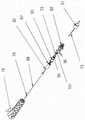
图1是激光破坏白内障晶状体组织的实施例的局部立体图;FIG. 1 is a partial perspective view of an embodiment of laser destruction of cataractous lens tissue;
图2是传输激光脉冲源的手持激光器械的实施例的局部立体图;2 is a partial perspective view of an embodiment of a hand-held laser instrument delivering a source of laser pulses;
图3是图2的手持激光器械的远侧尖端的示例的横截面图,其中抽吸针和光纤共线,并且抽吸通道的入口不受阻碍;FIG. 3 is a cross-sectional view of an example of the distal tip of the hand-held laser instrument of FIG. 2 with the aspiration needle and optical fiber in-line and with an unobstructed entrance to the aspiration channel;
图4是图2的手持激光器械的远侧尖端的示例的横截面图,其中组织碎片在负压作用下被拉向抽吸通道,该组织碎片过大无法被抽吸并且完全堵塞住抽吸通道入口;FIG. 4 is a cross-sectional view of an example of the distal tip of the hand-held laser instrument of FIG. 2 with tissue fragments that are too large to be aspirated and completely obstruct suction, being pulled toward the suction channel under negative pressure. channel entrance;
图5是图4的相同组织碎片在被破坏和抽吸时的示例的横截面图,堵塞物被部分或完全清除;Fig. 5 is a cross-sectional view of an example of the same tissue fragment of Fig. 4 when disrupted and aspirated, with the blockage partially or completely cleared;
图6是图2的手持激光器械的远侧尖端的示例的横截面图,其产生了持续性的堵塞,其中激光光纤破坏了其范围内的所有组织,但无法清除堵塞;6 is a cross-sectional view of an example of the distal tip of the hand-held laser instrument of FIG. 2 that creates a persistent blockage in which the laser fiber destroys all tissue within its reach, but fails to clear the blockage;
图7是示例手持激光器械的横截面图,其中光纤的远端可如此被设置在抽吸针内,即抽吸流体可被包含入可消毒或一次性使用的工具组件内,且不会污染光纤束传输的一些重复使用部分,同时允许非弹性光纤在抽吸通道内移动;7 is a cross-sectional view of an example hand-held laser instrument in which the distal end of the optical fiber can be positioned within the aspiration needle such that the aspiration fluid can be contained within the sterilizable or single-use tool assembly without contamination Some reused portions of fiber bundle delivery while allowing inelastic fibers to move within the pumping channel;
图8是图2的激光器械的实施例,其中该器械是为三个可分离部分;包括具有光纤接头的光纤的可重复使用的激光传输组件、包括带有用于冲洗的输出通道的远侧器械尖端的可拆式尖端手持组件、抽吸针和延伸光纤尖端,该延伸光纤尖端也包括用于将一次性管连接至一次性抽吸和冲洗装置的位置;和8 is an embodiment of the laser instrument of FIG. 2, wherein the instrument is three separable parts; a reusable laser delivery assembly including an optical fiber with fiber optic connectors, including a distal instrument with an output channel for irrigation a detachable tip hand-held assembly for the tip, an aspiration needle, and an extension fiber tip that also includes a location for attaching the disposable tubing to the disposable aspiration and irrigation device; and
图9是可替换式手持组件的分解图的示例,其中小光纤附接至光纤接头,该光纤接头连接至可重复使用的激光传输组件中的对应接头。9 is an example of an exploded view of a replaceable handheld assembly with a small optical fiber attached to a fiber optic connector connected to a corresponding connector in a reusable laser delivery assembly.
在不同的附图中,可能使用类似的元件符号来表示类似的元件。In different drawings, similar reference numerals may be used to refer to similar elements.
具体实施方式Detailed ways
在一些示例中,本发明提供了一种用于破坏和移除白内障晶状体组织的手持激光超声乳化设备。In some examples, the present invention provides a handheld laser phacoemulsification device for destroying and removing cataractous lens tissue.
在一些示例中,本发明提供了一种设备,其通过利用激光能来破坏接触到光纤尖端16的组织,相较于传统器械而言有助于为外科器械54提供改进的抽吸率。光纤尖端16共线地位于抽吸通道的小直径内,该抽吸通道适于在人眼的前囊内手动定位。光纤16可在抽吸通道内前进或后退以增强组织的抽吸率,并且还将破坏非意图抽吸组织的风险最小化。In some examples, the present invention provides a device that helps to provide an improved suction rate for the
在一些示例中,本发明通过算法整合了对流体(抽吸和冲洗装置)和激光破坏的控制,其中算法基于用户输入以及传感器输出(例如测量抽吸通道及冲洗通道内的压力及流量)来调整激光参数,例如脉冲频率、包络及激光尖端的定位,以通过最小射流(流动及真空)和对周围组织的最小破坏达到更快且更为精准的抽吸。In some examples, the present invention integrates control of fluids (aspiration and irrigation devices) and laser damage through algorithms, where algorithms are based on user input and sensor output (eg, measuring pressure and flow in suction and irrigation channels) Adjust laser parameters such as pulse frequency, envelope and laser tip positioning to achieve faster and more precise aspiration with minimal jet (flow and vacuum) and minimal disruption to surrounding tissue.
在一些示例中,本发明提供一种外科器械54,其中增强了用户对于抽吸率的控制,其做法为另外将可移动光纤16整合入冲洗/抽吸尖端,和控制系统算法,该控制系统算法对各项用户输入以及感测到的流体状况反馈并自动优化光纤位置和激光脉冲频率,以最小化对周围组织结构的侵入性损伤,并且限制前囊的压力变化并且最小化组织移除过程当中的抽吸和冲洗的流动。In some examples, the present invention provides a
本发明描述一种包括激光探针的设备,该激光探针与身体接触并且进入身体内部,其能够可通过对组织分子内部的选定振动模式的光学激励在时序上早于热扩散至周围地有效驱动组织的迅速分解。该激光探针使用类似于先前于WO2016041086A1所公开的激光机构,该专利通过引用整体并入本文。The present invention describes a device comprising a laser probe in contact with and into the interior of the body capable of dispersing to ambient temporally earlier than thermally by optical excitation of selected vibrational modes within tissue molecules Effectively drive rapid decomposition of the organization. The laser probe uses a laser mechanism similar to that previously disclosed in WO2016041086A1, which is hereby incorporated by reference in its entirety.
本发明针对于用于有效地破坏硬白内障组织同时避免能量传播至眼部其它组织的一种示例方法。The present invention is directed to an exemplary method for effectively destroying hard cataract tissue while avoiding energy transmission to other tissues of the eye.
参考图1,公开了一种示例激光消融方法。图1示出了激光破坏白内障晶状体组织1的说明。当具有选定的持续期间、波长和脉冲能量的激光脉冲(例如WO2016041086A1所公开的激光脉冲)联接至光波导12并且由光波导12的远端16离开时,产生激光破坏。光波导12已经穿过切口点7并穿过囊9内开口插入眼部的前房并指向白内障晶状体组织1的内部。光线被与光波导16的出口接触的晶状体细胞3或细胞间区域8强烈吸收,或在接近组织内的激光光学吸收深度40的距离内照射一定体积的组织5,在对眼部的远侧部分(例如角膜2或晶状体囊9)造成最小干扰情况下,对晶状体细胞及/或晶状体细胞结构4造成破坏并且有效分解和抽吸白内障组织6的破坏碎片。当连接至真空压力装置时,真空管或针13用作一种破坏组织的移除装置。抽吸通道52的内尖端包含光纤的远端16,激光脉冲从该远端发射。该激光脉冲破坏与其接触的组织,因而可将所产生物质自眼中吸出。Referring to Figure 1, an example laser ablation method is disclosed. Figure 1 shows an illustration of laser destruction of
此种激光能量的共线传输在小光纤及精准激光破坏过程中是有利的,因为组织通过抽吸压力被主动地拉向激光能量。本发明的接触式组织破坏并不限于晶状体组织而是能够应用于所有组织类型。This collinear delivery of laser energy is advantageous in small fibers and during precise laser destruction because tissue is actively pulled towards the laser energy by suction pressure. The contact tissue destruction of the present invention is not limited to lens tissue but can be applied to all tissue types.
值得注意的是,在实施例中提供了一种用于在外科手术过程当中移动或重新定位光纤尖端16的位置的装置以及基于用户输入和冲洗通道、抽吸通道内的流体状况来控制此位置的装置,见图2。Notably, a means for moving or repositioning the position of the
图2公开了一种本发明的实施例,其中手持器械54联接至激光脉冲源10。激光脉冲源10受到来自控制电路21的信号22控制,而后者也控制抽吸工具18和冲洗工具17。激光脉冲源10还接收来自一个或多个传感器的输入,例如流体通道内的流量传感器38和压力传感器48。通过使用用户输入装置11(例如多功能脚踏板)以及存储在控制电路21中的预设参数,冲洗、抽吸压力、抽吸流量、激光功率、脉冲频率及光纤位置的动作可得以进一步地控制。可提供其它控制装置。预设参数可包含最大流量与压力限制、激光功率限制以及其它操作模式。冲洗和抽吸通道52可联接至柔性管100(见图8),其进一步地联接至组件19,组件19可为可拆式、可重复使用或是一次性。柔性管100允许在眼睛晶状体1内插入和控制工具组件19的远侧尖端20,以得到在该尖端处对于白内障组织的可控的微破坏,见图1。在一个示例中,提供了一种用于移动光纤12的工具24(例如驱动机构,比如由旋转电机、音圈致动器等驱动的线性马达、线性平移机构等),以控制远侧光纤尖端16与抽吸通道52的远端之间的相对距离。还可提供传感器或编码器53(例如光声传感器)以追踪光纤尖端的位置。还可提供另一传感器以检测光纤12与组织之间何时进行物理接触。FIG. 2 discloses an embodiment of the present invention in which a hand-held
光纤12在一些示例中可由任意适用材料构成,如蓝宝石、金刚石、氯化物玻璃(ZBLAN)或钇铝石榴石(YAG)。光纤尖端16可为直线状或具有任意其它适用构型,例如像WO2016041086A1所述的曲线状、锥形或是斜角状。
用户可以多种不同的方式来控制光纤尖端16的位置。在一个实施例中,提供了一种附加用户输入装置,其被配置为可前后移动光纤位置。在另一个实施例中,使用通常用于传统过程中以增加流量/抽吸压力的比例踏板来推进光纤。踏板的致动导致更高程度的抽吸,并且同时激光破坏机构距离抽吸尖端的接近度也得以降低。The user can control the position of the
在一些示例中,光纤尖端16的位置可基于抽吸通道52的压力及流量对于用户对更高程度抽吸的需求的反应例如通过感测尖端处的堵塞程度而自动地调整。在此实施例中,光纤尖端16的位置可由外科医生直接决定或是与控制算法结合,该控制算法能够感测抽吸通道52内的流体状况并且识别多种情况包括堵塞和的不受阻碍的流动。在一些示例中,自动调整可与直接用户输入结合使用以控制光纤头部16的位置。In some examples, the position of the
在传统白内障外科手术系统中,用户能够对抽吸进行控制(例如通过脚踏板)。传统系统中可包括一些简单的自动控制,以在压力过高时限制流动。在本发明中,提供了对系统更加综合性的控制,其中在考虑检测到的压力及流动的同时以及同样在控制光纤的定位的同时激光参数也受到了控制。例如,流动可能因压力过高而受到限制,且进一步地,系统可控制激光开启并且控制光纤朝向尖端以作为降低压力的一种方式向远侧移动。此种综合性控制的进一步细节在下文进行描述。In conventional cataract surgery systems, the user can control suction (eg, via a foot pedal). Some simple automatic controls can be included in conventional systems to restrict flow when the pressure is too high. In the present invention, a more integrated control of the system is provided, wherein the laser parameters are controlled while taking into account the detected pressure and flow and also controlling the positioning of the fiber. For example, flow may be restricted due to excessive pressure, and further, the system may control the laser to turn on and control the fiber to move distally toward the tip as a way to lower the pressure. Further details of this comprehensive control are described below.
参照图3,在无阻碍情况下,抽吸通道52内流动与压力之间的关系可通过考虑层流及圆形截面管内的牛顿流体来估计,其中层流可根据泊肃叶定律来考虑。Referring to Figure 3, the relationship between flow and pressure in the

其中,
针对期望抽吸流量给定用户控制信号,其可于0至100%之间变化,用户可期望流动遵循达到最大压力的控制信号。Given a user control signal, which can vary from 0 to 100%, for the desired suction flow, the user can expect the flow to follow the control signal to reach the maximum pressure.
Q∝A(Δp)forΔp<Δpmax or Q∝A(Δpmax)Q∝A(Δp)forΔp<Δpmax or Q∝A(Δpmax )
在有限的压力下,重要的是考虑防止高粘度组织堵塞抽吸通道52的方法。例如,为了最小化下游的堵塞,抽吸通道52的尖端51可为锥形,从而入口直径小于抽吸通道52的直径。在抽吸通道52入口内传输的激光能量因而可用于防止抽吸通道52中的不需要的堵塞。还有利的是在无阻碍的情况下直接将光纤推至通道外,其中可使用小直径光纤作为雕刻或是高精度破坏工具,而此时抽吸通道52的压力或流动几乎为零。然而在高流动抽吸模式中,并不需要激光在无阻碍的情况下破坏组织,且泊肃叶定律将成立。借着监测压力、流动参数及其变化率,可确认是否有阻塞发生,详述于下。With limited pressures, it is important to consider ways to prevent clogging of
进一步参考图3,公开了示例装置的插入。图3示出示例器械54的远侧尖端,其中抽吸针13和光纤12为共线且抽吸通道52的入口未受到阻碍。抽吸通道52内的压力低,流量不受到压力限制。在此示例中,光纤尖端16的位置并非关键,其可在抽吸针当中回缩几毫米。在一些示例中,光纤尖端16可向远侧最多回缩至且包括约5毫米以上的范围;且向近侧最多至且包括约10毫米的范围。根据人眼大小并取决于特定应用,其它距离亦为可行。于回缩位置使用的激光能量有助于进一步破坏由负压吸入抽吸通道52内的组织碎片。在此模式中,器械54以类似传统抽吸/冲洗器械尖端的方式动作。对晶状体囊的抽吸不太可能与光纤接触且可在意外抽吸时仍然维持。With further reference to Figure 3, insertion of an example device is disclosed. FIG. 3 shows the distal tip of an
在外科手术过程期望采用抽吸针保持住一块组织,直到该块组织被适当地定位于前房内以进行能量破坏。一旦一块组织被抽吸压力吸住,其就会填入抽吸通道52的入口并且在无增加压力的情况下堵住进一步的移除。During surgical procedures it is desirable to use an aspiration needle to hold a piece of tissue until the piece of tissue is properly positioned within the anterior chamber for energy disruption. Once a piece of tissue is sucked by suction pressure, it fills the inlet of
图4示出了当光纤回缩时发生堵塞的示例。组织碎片81通过负压而被拉向抽吸通道52,且太大而无法被抽吸入,完全堵塞了抽吸通道52的入口。在此示例情况中,抽吸通道52内的压力作为流量的函数增加,有利的是朝向抽吸通道52的入口推进激光光纤以破坏造成阻碍的组织,而非尝试以更高压抽吸。Figure 4 shows an example of clogging when the fiber is retracted. The tissue fragments 81 are pulled towards the
此外,在此实施例中,若光纤没有突伸出,那么抽吸针就可更佳地保持住该堵塞,否则该光纤本身如不是被埋在堵塞组织碎片中,就是防止发生任何堵塞。组织碎片通过由组织碎片周围与抽吸通道52内部之间的压力差所引起的力来被保持在抽吸针的尖端,在此情况下,假设泊肃叶定律中的R与L为固定值,由于没有体积可流过阻塞,因此Q趋近于0,因而压力与流量之间的关系大幅度地偏离泊肃叶定律。Furthermore, in this embodiment, if the fiber does not protrude, the suction needle is better able to hold the blockage, otherwise the fiber itself is either buried in the blockage tissue debris, or prevents any blockage from occurring. The tissue fragment is held at the tip of the aspiration needle by the force caused by the pressure difference between the surrounding tissue fragment and the interior of the

Q=0的解仅在Δp=0(泵关闭且该块组织未被保持住)或粘度实际上变得无限大η→∞的情况下出现。尽管堵住了,泵仍会继续尝试并且抽吸,压力变得与控制信号成比例并且快速增长至其极限值。The solution for Q=0 only occurs if Δp=0 (the pump is off and the mass tissue is not held) or if the viscosity becomes practically infinite η→∞. Despite the blockage, the pump will continue to try and pump, the pressure becomes proportional to the control signal and rapidly increases to its limit.
Δp∝A forΔp<Δpmax orΔp=ΔpmaxΔp∝A forΔp<Δpmax orΔp=Δpmax
达到压力极限值所需的时间通常被称为抽吸流体系统的‘上升时间’τ。The time required to reach the pressure limit is often referred to as the 'rise time' τ of the pumped fluid system.
通过随时间监测压力与流动,若当压力上升时流量下降,则算法可预测堵塞。换句话说,当未受阻碍且低于压力及流量限制时,控制信号和抽吸率被明确限定。By monitoring pressure and flow over time, the algorithm can predict blockage if flow drops as pressure rises. In other words, when unobstructed and below the pressure and flow limits, the control signal and suction rate are well defined.
Q∝A(Δp)且因此控制信号下的流量的变化率被明确定义
然而,当堵塞时,对于流动的附加需求即增加A并不会导致附加的流动:Q=0并且

假设在发生阻塞的同时控制信号未产生变化

但是,一旦发生阻塞,由于初始流量Q0开始往下掉至0,


在此实施例中,传统的超声机器操作者将开始使用更高的真空压或超声来破坏阻塞。In this embodiment, a conventional ultrasound machine operator would begin using higher vacuum pressures or ultrasound to break the blockage.
图5公开了一种装置,通过该装置激光光纤有助于从阻塞过渡到无阻塞。换句话说,图5公开了组织碎片被破坏和抽吸以及堵塞被局部或完全清除,激光光纤可开始回缩直至产生另一次堵塞。一旦堵塞开始清除且压力不再随着流量大幅度增加,可减小激光功率或是激光尖端可缩回以避免残留的组织碎片被推离尖端。堵塞越大,光纤就应越接近抽吸通道52的堵塞入口。Figure 5 discloses a device by which a laser fiber facilitates the transition from blocked to unblocked. In other words, Figure 5 discloses that the tissue fragments are disrupted and aspirated and the blockage is partially or completely cleared, and the laser fiber can begin to retract until another blockage is created. Once the blockage begins to clear and the pressure no longer increases substantially with flow, the laser power can be reduced or the laser tip can be retracted to avoid residual tissue fragments being pushed away from the tip. The greater the blockage, the closer the fiber should be to the blocked entrance of the
在一些示例中,可定义简单的控制算法以仅基于压力如下确定光纤尖端的位置:In some examples, a simple control algorithm can be defined to determine the position of the fiber tip based only on pressure as follows:

D为光纤尖端距抽吸通道52入口的距离。D is the distance from the tip of the fiber to the inlet of the
在一些示例中,光纤位置可由流量来设定。In some examples, the fiber position may be set by traffic.

于一些示例中,光纤的位置可由压力及流动的相对变化来确定。In some examples, the position of the fiber may be determined by relative changes in pressure and flow.

在一些示例中,光纤位置可简单地链接至用户控制信号,该用户控制信号通常仅控制假设用户需要更高程度抽吸的抽吸动作,将需要激光辅助且因而有较低的D值。In some examples, the fiber position may simply be linked to a user control signal that typically only controls the suction action assuming that the user needs a higher degree of suction, will require laser assistance and thus have a lower D value.
D(t)∝1-A(t).D(t)∝1-A(t).
上述示例算法并不意味着限制。其他的示例控制算法也可行。The above example algorithms are not meant to be limiting. Other example control algorithms are also possible.
图6公开了一种情况,其中,堵塞长期持续且无法于特定时间t>>τ之内被清除。在此情况下,光纤位置可在通道内纵向振荡,以提高高精度激光破坏的有效范围并且增加对于此效果的机械补强(类似摆动组织)。在此示例情况下,控制算法可假设若脚踏板被完全按下的时间长于设定时间,该设定时间远大于上升时间且压力仍为最大值,则光纤的移动变成振荡模式。这是因为在压力未降低时对于抽吸的延长输入可指示为堵塞尚未被清除且需要更多的机械辅助。Figure 6 discloses a situation in which the blockage persists for a long time and cannot be cleared within a certain time t>>τ. In this case, the fiber position can oscillate longitudinally within the channel to increase the effective range of high-precision laser destruction and to increase mechanical reinforcement for this effect (similar to oscillating tissue). In this example case, the control algorithm may assume that if the foot pedal is fully depressed for longer than a set time, which is much longer than the rise time and the pressure is still at a maximum value, the movement of the fiber becomes an oscillatory mode. This is because prolonged input to suction when the pressure is not reduced may indicate that the blockage has not been cleared and more mechanical assistance is required.
在进一步的实施例中,激光脉冲频率、包络及光纤位置均用于使前囊内的总流动及压力变化最小化,以实现最小化的微创组织移除,最重要的是防止对囊的非意图破坏或通过激光能量、机械力或流体对角膜内皮细胞造成损伤。激光脉冲的平均功率为脉冲频率和每脉冲能量的函数。为激光组织破坏给定特定的激光强度阈值,其在维持恒定脉冲能量以及通过减少脉冲频率(非衰减激光功率)来衰减激光功率上是有用的。在本发明中,当激光脉冲频率未被平均划分时会产生器械54动作的增强,但相对地会有一个时间区段,在该时间区段中激光动作以较低频包络来调制。已经发现约5Hz的包络频率适用于硬化的眼组织。脉冲频率可在包络频率下以接近激光脉冲的0-100%脉冲宽度调制来增加或减少。In a further embodiment, the laser pulse frequency, envelope, and fiber position are all used to minimize total flow and pressure changes within the anterior capsule to achieve minimally invasive tissue removal and, most importantly, prevent damage to the capsule Unintended destruction or damage to corneal endothelial cells by laser energy, mechanical force, or fluid. The average power of a laser pulse is a function of pulse frequency and energy per pulse. Given a specific laser intensity threshold for laser tissue destruction, it is useful in maintaining a constant pulse energy and attenuating the laser power by reducing the pulse frequency (non-attenuating laser power). In the present invention, an enhancement of the motion of the
假设激光脉冲在光纤尖端强烈地加热一定体积的组织/液体。由于尖端为硬质的且该区域(约200微米)远大于抽吸深度(约1微米),因此被照射到的物质无法向后膨胀入固体光纤内且存在合力将组织推离纤推。该膨胀力引起压力增加,其抵消了抽吸泵的真空压力。通过在堵塞期间使激光暂停一段时间,抽吸泵可产生更高的压力,由激光脉冲所引起的压力变化不太可能累积至足以反转抽吸通道中压力的符号(并导致组织拆离)。It is assumed that the laser pulses intensely heat a volume of tissue/fluid at the fiber tip. Since the tip is rigid and this area (about 200 microns) is much larger than the suction depth (about 1 micron), the irradiated material cannot expand back into the solid fiber and there is a resultant force that pushes the tissue away from the fiber. This expansion force causes a pressure increase, which counteracts the vacuum pressure of the suction pump. By pausing the laser for a period of time during occlusion, the aspiration pump can generate higher pressures, and the pressure changes caused by the laser pulses are less likely to accumulate enough to reverse the sign of the pressure in the aspiration channel (and cause tissue detachment) .
参考图7,在一些示例中,光纤远端16可如此设置于抽吸针13内,即使得抽吸流体72被包含在可消毒或单次使用工具组件19内且不污染到光纤束传输12的一些可重复使用部分,同时允许非弹性光纤在抽吸通道内移动。在一些示例中,这可借助于压缩橡胶密封件73来实现,在该压缩橡胶密封件内光纤被固定在移动轴组件74中。工具组件19包含冲洗通道70和抽吸通道71,此两者连接至远侧尖端及管接头,利用管接头来弹性地连接流体控制装置。Referring to FIG. 7 , in some examples, the fiber optic
参考图8,在一些示例中,器械54包括三个可分离部分:可重复使用的激光传输组件75(其包括光纤12并且具有光纤接头78):可拆式尖端手柄组件76(其包括远侧器械尖端20,该远侧器械尖端20具有冲洗用输出通道51、抽吸针13以及延伸光纤尖端16,该延伸光纤尖端16在其矢状端部联接至可重复使用传输系统的光纤接头78);以及一次性抽吸和冲洗装置100。可提供用于将一次性管100连接至尖端手柄组件76的连接点;或是可预先组装两个一次性部件。8, in some examples, the
参考图9,其公开了可更换式手柄组件76的分解图。小光纤88附接至光纤接头79,光纤接头79与可重复使用的激光传输组件的对应接头78连接。轴组件82允许光纤通过垫圈73来密封,垫圈73环绕轴组件82地由螺母87压缩。螺母87由轴组件和弹簧101所保持,弹簧101作用为当未连接至可重复使用的组件部分时使光纤尖端回缩。歧管92(其上置有抽吸针13以及远侧冲洗套51)通过歧管延伸部93以及密封垫圈96联接至手柄组件19的冲洗通道70以及抽吸通道71,以保持通道分离。光纤轴组件通过轴密封螺母87附接至歧管延伸部93。Referring to Figure 9, an exploded view of the
本文所用的术语“包括”及“包含”应该被解释为包含性及开放性的,而非排除性的。具体来说,当在包括权利要求书的此说明书中使用时,术语“包括”和“包含”以及该术语的变型体表示特定特征、步骤或组件被包括在内。这些术语不应被解释为排除其它特征、步骤或零部件的存在。The terms "including" and "comprising" as used herein should be construed as inclusive and open-ended, rather than exclusive. In particular, when used in this specification including the claims, the terms "comprising" and "comprising" and variations of the terms mean that the specified feature, step or component is included. These terms should not be interpreted as excluding the presence of other features, steps or components.
已经给出了本发明的优选实施例的前述描述以说明本发明的原理,但并不旨在将本发明限制于说明的具体实施例。本发明的范围旨在由所附权利要求及其等同方案中包含的所有实施方式限定。The foregoing description of the preferred embodiments of the present invention has been presented to illustrate the principles of the invention, but is not intended to limit the invention to the particular embodiments illustrated. It is intended that the scope of the invention be defined by all embodiments contained in the appended claims and their equivalents.
Claims (10)
Priority Applications (1)
| Application Number | Priority Date | Filing Date | Title |
|---|---|---|---|
| CN202210423710.XACN114886662B (en) | 2017-09-27 | 2018-09-21 | Surgical instrument for minimally invasive aspiration of tissue |
Applications Claiming Priority (3)
| Application Number | Priority Date | Filing Date | Title |
|---|---|---|---|
| US201762564019P | 2017-09-27 | 2017-09-27 | |
| US62/564019 | 2017-09-27 | ||
| PCT/CA2018/051186WO2019060987A1 (en) | 2017-09-27 | 2018-09-21 | Surgical instrument for minimally invasive aspiration of tissue |
Related Child Applications (1)
| Application Number | Title | Priority Date | Filing Date |
|---|---|---|---|
| CN202210423710.XADivisionCN114886662B (en) | 2017-09-27 | 2018-09-21 | Surgical instrument for minimally invasive aspiration of tissue |
Publications (2)
| Publication Number | Publication Date |
|---|---|
| CN111093573A CN111093573A (en) | 2020-05-01 |
| CN111093573Btrue CN111093573B (en) | 2022-05-17 |
Family
ID=65807057
Family Applications (2)
| Application Number | Title | Priority Date | Filing Date |
|---|---|---|---|
| CN202210423710.XAActiveCN114886662B (en) | 2017-09-27 | 2018-09-21 | Surgical instrument for minimally invasive aspiration of tissue |
| CN201880055421.0AActiveCN111093573B (en) | 2017-09-27 | 2018-09-21 | Surgical instrument for minimally invasive aspiration of tissue |
Family Applications Before (1)
| Application Number | Title | Priority Date | Filing Date |
|---|---|---|---|
| CN202210423710.XAActiveCN114886662B (en) | 2017-09-27 | 2018-09-21 | Surgical instrument for minimally invasive aspiration of tissue |
Country Status (9)
| Country | Link |
|---|---|
| US (2) | US10925769B2 (en) |
| EP (1) | EP3661467B1 (en) |
| JP (2) | JP7412333B2 (en) |
| CN (2) | CN114886662B (en) |
| AU (1) | AU2018340882B2 (en) |
| CA (1) | CA3070882A1 (en) |
| ES (1) | ES2984311T3 (en) |
| TW (2) | TWI870901B (en) |
| WO (1) | WO2019060987A1 (en) |
Families Citing this family (7)
| Publication number | Priority date | Publication date | Assignee | Title |
|---|---|---|---|---|
| WO2019060987A1 (en)* | 2017-09-27 | 2019-04-04 | Light Matter Interaction Inc. | Surgical instrument for minimally invasive aspiration of tissue |
| AU2019353187B2 (en)* | 2018-10-05 | 2024-07-25 | Alcon Inc. | Occlusion sensing in ophthalmic laser probes |
| WO2023026448A1 (en)* | 2021-08-26 | 2023-03-02 | オリンパス株式会社 | Perfusion device and perfusion method |
| CN118055746A (en) | 2021-10-08 | 2024-05-17 | 爱尔康公司 | High efficiency laser for tissue disruption |
| CA3228513A1 (en) | 2021-10-15 | 2023-04-20 | David Jung | Dynamic laser pulse control |
| WO2025073058A1 (en)* | 2023-10-04 | 2025-04-10 | Light Matter Interaction Inc. | Systems, devices and methods for laser-assisted targeted intracorporeal therapy |
| CN118593238B (en)* | 2024-07-27 | 2024-11-22 | 嘉兴犀燃医疗器械有限公司 | Ultrasonic emulsification equipment for ophthalmic surgery |
Citations (1)
| Publication number | Priority date | Publication date | Assignee | Title |
|---|---|---|---|---|
| US5741244A (en)* | 1994-03-09 | 1998-04-21 | Klaas; Dieter | Probe for the suctioning of ocular tissue |
Family Cites Families (23)
| Publication number | Priority date | Publication date | Assignee | Title |
|---|---|---|---|---|
| US5196027A (en)* | 1990-05-02 | 1993-03-23 | Thompson Keith P | Apparatus and process for application and adjustable reprofiling of synthetic lenticules for vision correction |
| CN1160530A (en)* | 1995-10-27 | 1997-10-01 | Ir视力公司 | Method and apparatus for removing corneal tissue with infrared laser radiation |
| US5782823A (en)* | 1996-04-05 | 1998-07-21 | Eclipse Surgical Technologies, Inc. | Laser device for transmyocardial revascularization procedures including means for enabling a formation of a pilot hole in the epicardium |
| US5864397A (en)* | 1997-09-15 | 1999-01-26 | Lockheed Martin Energy Research Corporation | Surface-enhanced raman medical probes and system for disease diagnosis and drug testing |
| US6471692B1 (en)* | 1998-06-24 | 2002-10-29 | Laser Industries Ltd. | System and method for manipulating movement of an energy emitting device within a body cavity |
| DE60131273T2 (en)* | 2000-05-19 | 2008-08-28 | Michael S. Beverly Hills Berlin | LASER APPLICATION SYSTEM AND METHOD FOR EYE-USE |
| US6517531B2 (en)* | 2001-04-27 | 2003-02-11 | Scimed Life Systems, Inc. | Medical suction device |
| JP2003130796A (en)* | 2001-06-28 | 2003-05-08 | Fuji Photo Film Co Ltd | Method for creating data for biochemical analysis and scanner used therefor |
| US20030003594A1 (en)* | 2001-06-28 | 2003-01-02 | Fuji Photo Film Co. Ltd. | Method for producing biochemical analysis data and scanner used therefor |
| US7182759B2 (en)* | 2001-09-07 | 2007-02-27 | Advanced Medical Optics, Inc. | Cataract extraction apparatus and method with rapid pulse phaco power |
| US7485116B2 (en)* | 2004-09-22 | 2009-02-03 | Densen Cao | Laser systems, with a fiber storage and dispensing unit, useful in medicine and dentistry |
| EP1909716A1 (en)* | 2005-06-29 | 2008-04-16 | SK Technologies GmbH | Medical device and method |
| CN1951346A (en)* | 2006-08-30 | 2007-04-25 | 周克俭 | Cataract cutter |
| EP2200549A4 (en)* | 2007-09-18 | 2013-01-23 | Alcon Lensx Inc | Methods and apparatus for integrated cataract surgery |
| RU2477110C2 (en)* | 2011-02-04 | 2013-03-10 | Федеральное государственное учреждение "Межотраслевой научно-технический комплекс "Микрохирургия глаза" имени академика С.Н. Федорова Федерального агентства по высокотехнологичной медицинской помощи" | Laser ophthalmologic multifunctional system |
| CA2836973C (en)* | 2011-06-27 | 2016-08-16 | Wavelight Gmbh | Apparatus for eye surgery |
| EP2763636B1 (en)* | 2011-10-03 | 2017-12-06 | Biolase, Inc. | Systems for disruption of an eye lens |
| US20140052113A1 (en)* | 2012-08-17 | 2014-02-20 | Carl Zeiss Meditec Ag | Instrument system and procedure for phacoemulsification |
| CN105228514B (en)* | 2013-03-15 | 2019-01-22 | 阿维格公司 | Optical Pressure Sensor Assembly |
| WO2014201165A1 (en)* | 2013-06-11 | 2014-12-18 | Auris Surgical Robotics, Inc. | System for robotic assisted cataract surgery |
| AU2014354716B2 (en)* | 2013-11-28 | 2018-12-06 | Alcon Inc. | Ophtalmic surgical systems, methods, and devices |
| ES2900333T3 (en)* | 2014-09-18 | 2022-03-16 | Light Matter Interaction Inc | Laser device for the treatment of a cataractic lens |
| WO2019060987A1 (en)* | 2017-09-27 | 2019-04-04 | Light Matter Interaction Inc. | Surgical instrument for minimally invasive aspiration of tissue |
- 2018
- 2018-09-21WOPCT/CA2018/051186patent/WO2019060987A1/ennot_activeCeased
- 2018-09-21AUAU2018340882Apatent/AU2018340882B2/enactiveActive
- 2018-09-21CNCN202210423710.XApatent/CN114886662B/enactiveActive
- 2018-09-21TWTW112122652Apatent/TWI870901B/enactive
- 2018-09-21USUS16/137,894patent/US10925769B2/enactiveActive
- 2018-09-21JPJP2020517355Apatent/JP7412333B2/enactiveActive
- 2018-09-21TWTW107133508Apatent/TWI808997B/enactive
- 2018-09-21CACA3070882Apatent/CA3070882A1/enactivePending
- 2018-09-21EPEP18860632.1Apatent/EP3661467B1/enactiveActive
- 2018-09-21ESES18860632Tpatent/ES2984311T3/enactiveActive
- 2018-09-21CNCN201880055421.0Apatent/CN111093573B/enactiveActive
- 2021
- 2021-01-21USUS17/154,399patent/US11833082B2/enactiveActive
- 2023
- 2023-08-18JPJP2023133188Apatent/JP7604763B2/enactiveActive
Patent Citations (1)
| Publication number | Priority date | Publication date | Assignee | Title |
|---|---|---|---|---|
| US5741244A (en)* | 1994-03-09 | 1998-04-21 | Klaas; Dieter | Probe for the suctioning of ocular tissue |
Also Published As
| Publication number | Publication date |
|---|---|
| AU2018340882B2 (en) | 2023-12-07 |
| CA3070882A1 (en) | 2019-04-04 |
| JP2023164846A (en) | 2023-11-14 |
| TW202337411A (en) | 2023-10-01 |
| CN114886662B (en) | 2025-07-25 |
| TWI808997B (en) | 2023-07-21 |
| US10925769B2 (en) | 2021-02-23 |
| JP7604763B2 (en) | 2024-12-24 |
| TW201929795A (en) | 2019-08-01 |
| US20210137739A1 (en) | 2021-05-13 |
| AU2018340882A1 (en) | 2020-02-13 |
| JP7412333B2 (en) | 2024-01-12 |
| EP3661467A4 (en) | 2021-04-28 |
| EP3661467A1 (en) | 2020-06-10 |
| TWI870901B (en) | 2025-01-21 |
| US20190091067A1 (en) | 2019-03-28 |
| US11833082B2 (en) | 2023-12-05 |
| EP3661467B1 (en) | 2024-03-06 |
| CN114886662A (en) | 2022-08-12 |
| ES2984311T3 (en) | 2024-10-29 |
| CN111093573A (en) | 2020-05-01 |
| JP2020534924A (en) | 2020-12-03 |
| WO2019060987A1 (en) | 2019-04-04 |
Similar Documents
| Publication | Publication Date | Title |
|---|---|---|
| CN111093573B (en) | Surgical instrument for minimally invasive aspiration of tissue | |
| JP7550645B2 (en) | Ultraviolet laser vitrectomy probe | |
| JP4664325B2 (en) | Cleaning / suction tip | |
| US7967799B2 (en) | Liquefaction handpiece tip | |
| WO2004004587A1 (en) | Laser surgical handpiece with photon trap | |
| EP1388331B1 (en) | Liquefaction handpiece tip | |
| WO2006124290A2 (en) | Phacoemulsification tip | |
| WO2006101717A2 (en) | Phacoemulsification tip | |
| CA2539421C (en) | Phacoemulsification needle | |
| WO2006096335A2 (en) | Phacoemulsification tip | |
| US20240074902A1 (en) | Devices and methods for improved followability in laser-based ocular procedures |
Legal Events
| Date | Code | Title | Description |
|---|---|---|---|
| PB01 | Publication | ||
| PB01 | Publication | ||
| SE01 | Entry into force of request for substantive examination | ||
| SE01 | Entry into force of request for substantive examination | ||
| GR01 | Patent grant | ||
| GR01 | Patent grant |