CN111084658A - Freezing adhesion device - Google Patents
Freezing adhesion deviceDownload PDFInfo
- Publication number
- CN111084658A CN111084658ACN202010205281.XACN202010205281ACN111084658ACN 111084658 ACN111084658 ACN 111084658ACN 202010205281 ACN202010205281 ACN 202010205281ACN 111084658 ACN111084658 ACN 111084658A
- Authority
- CN
- China
- Prior art keywords
- thimble
- needle
- valve body
- assembly
- channel
- Prior art date
- Legal status (The legal status is an assumption and is not a legal conclusion. Google has not performed a legal analysis and makes no representation as to the accuracy of the status listed.)
- Granted
Links
- 238000007710freezingMethods0.000titleclaimsabstractdescription23
- 230000008014freezingEffects0.000titleclaimsabstractdescription23
- 230000009471actionEffects0.000claimsabstractdescription9
- 230000001960triggered effectEffects0.000claimsabstractdescription8
- 238000003825pressingMethods0.000claimsdescription93
- 238000001125extrusionMethods0.000claimsdescription34
- 230000008859changeEffects0.000claimsdescription4
- 230000006835compressionEffects0.000claimsdescription3
- 238000007906compressionMethods0.000claimsdescription3
- 230000000149penetrating effectEffects0.000claimsdescription3
- 239000000853adhesiveSubstances0.000claims5
- 230000001070adhesive effectEffects0.000claims5
- 230000008878couplingEffects0.000claims3
- 238000010168coupling processMethods0.000claims3
- 238000005859coupling reactionMethods0.000claims3
- 238000007789sealingMethods0.000description20
- 238000000034methodMethods0.000description15
- 238000010586diagramMethods0.000description14
- 230000008569processEffects0.000description8
- CURLTUGMZLYLDI-UHFFFAOYSA-NCarbon dioxideChemical compoundO=C=OCURLTUGMZLYLDI-UHFFFAOYSA-N0.000description6
- 238000005452bendingMethods0.000description4
- 238000000605extractionMethods0.000description4
- 210000003811fingerAnatomy0.000description4
- 230000003902lesionEffects0.000description4
- 230000007246mechanismEffects0.000description4
- 210000003813thumbAnatomy0.000description4
- 229910002092carbon dioxideInorganic materials0.000description3
- 239000001569carbon dioxideSubstances0.000description3
- 230000000694effectsEffects0.000description3
- 210000005224forefingerAnatomy0.000description3
- 239000000463materialSubstances0.000description3
- 229920001296polysiloxanePolymers0.000description3
- GQPLMRYTRLFLPF-UHFFFAOYSA-NNitrous OxideChemical compound[O-][N+]#NGQPLMRYTRLFLPF-UHFFFAOYSA-N0.000description2
- 230000005540biological transmissionEffects0.000description2
- 210000004247handAnatomy0.000description2
- 238000005070samplingMethods0.000description2
- 206010011409Cross infectionDiseases0.000description1
- 208000012266Needlestick injuryDiseases0.000description1
- 206010029803Nosocomial infectionDiseases0.000description1
- 230000005680Thomson effectEffects0.000description1
- 230000009286beneficial effectEffects0.000description1
- 230000015572biosynthetic processEffects0.000description1
- 230000000903blocking effectEffects0.000description1
- 238000001816coolingMethods0.000description1
- 230000006872improvementEffects0.000description1
- 238000003780insertionMethods0.000description1
- 230000037431insertionEffects0.000description1
- 238000009434installationMethods0.000description1
- 239000011159matrix materialSubstances0.000description1
- 238000012986modificationMethods0.000description1
- 230000004048modificationEffects0.000description1
- 238000003032molecular dockingMethods0.000description1
- 239000001272nitrous oxideSubstances0.000description1
- 238000005057refrigerationMethods0.000description1
- 238000000926separation methodMethods0.000description1
- 210000003437tracheaAnatomy0.000description1
Images


Classifications
- A—HUMAN NECESSITIES
- A61—MEDICAL OR VETERINARY SCIENCE; HYGIENE
- A61B—DIAGNOSIS; SURGERY; IDENTIFICATION
- A61B18/00—Surgical instruments, devices or methods for transferring non-mechanical forms of energy to or from the body
- A61B18/02—Surgical instruments, devices or methods for transferring non-mechanical forms of energy to or from the body by cooling, e.g. cryogenic techniques
- A61B18/0218—Surgical instruments, devices or methods for transferring non-mechanical forms of energy to or from the body by cooling, e.g. cryogenic techniques with open-end cryogenic probe, e.g. for spraying fluid directly on tissue or via a tissue-contacting porous tip
- A—HUMAN NECESSITIES
- A61—MEDICAL OR VETERINARY SCIENCE; HYGIENE
- A61B—DIAGNOSIS; SURGERY; IDENTIFICATION
- A61B18/00—Surgical instruments, devices or methods for transferring non-mechanical forms of energy to or from the body
- A61B18/02—Surgical instruments, devices or methods for transferring non-mechanical forms of energy to or from the body by cooling, e.g. cryogenic techniques
- A—HUMAN NECESSITIES
- A61—MEDICAL OR VETERINARY SCIENCE; HYGIENE
- A61B—DIAGNOSIS; SURGERY; IDENTIFICATION
- A61B1/00—Instruments for performing medical examinations of the interior of cavities or tubes of the body by visual or photographical inspection, e.g. endoscopes; Illuminating arrangements therefor
- A61B1/00131—Accessories for endoscopes
- A61B1/00133—Drive units for endoscopic tools inserted through or with the endoscope
- A—HUMAN NECESSITIES
- A61—MEDICAL OR VETERINARY SCIENCE; HYGIENE
- A61B—DIAGNOSIS; SURGERY; IDENTIFICATION
- A61B17/00—Surgical instruments, devices or methods
- A61B2017/00017—Electrical control of surgical instruments
- A—HUMAN NECESSITIES
- A61—MEDICAL OR VETERINARY SCIENCE; HYGIENE
- A61B—DIAGNOSIS; SURGERY; IDENTIFICATION
- A61B17/00—Surgical instruments, devices or methods
- A61B2017/0046—Surgical instruments, devices or methods with a releasable handle; with handle and operating part separable
- A61B2017/00469—Surgical instruments, devices or methods with a releasable handle; with handle and operating part separable for insertion of instruments, e.g. guide wire, optical fibre
- A—HUMAN NECESSITIES
- A61—MEDICAL OR VETERINARY SCIENCE; HYGIENE
- A61B—DIAGNOSIS; SURGERY; IDENTIFICATION
- A61B18/00—Surgical instruments, devices or methods for transferring non-mechanical forms of energy to or from the body
- A61B2018/00005—Cooling or heating of the probe or tissue immediately surrounding the probe
- A61B2018/00011—Cooling or heating of the probe or tissue immediately surrounding the probe with fluids
- A61B2018/00017—Cooling or heating of the probe or tissue immediately surrounding the probe with fluids with gas
- A—HUMAN NECESSITIES
- A61—MEDICAL OR VETERINARY SCIENCE; HYGIENE
- A61B—DIAGNOSIS; SURGERY; IDENTIFICATION
- A61B18/00—Surgical instruments, devices or methods for transferring non-mechanical forms of energy to or from the body
- A61B2018/00005—Cooling or heating of the probe or tissue immediately surrounding the probe
- A61B2018/00011—Cooling or heating of the probe or tissue immediately surrounding the probe with fluids
- A61B2018/00023—Cooling or heating of the probe or tissue immediately surrounding the probe with fluids closed, i.e. without wound contact by the fluid
- A—HUMAN NECESSITIES
- A61—MEDICAL OR VETERINARY SCIENCE; HYGIENE
- A61B—DIAGNOSIS; SURGERY; IDENTIFICATION
- A61B18/00—Surgical instruments, devices or methods for transferring non-mechanical forms of energy to or from the body
- A61B2018/00571—Surgical instruments, devices or methods for transferring non-mechanical forms of energy to or from the body for achieving a particular surgical effect
- A61B2018/00619—Welding
- A—HUMAN NECESSITIES
- A61—MEDICAL OR VETERINARY SCIENCE; HYGIENE
- A61B—DIAGNOSIS; SURGERY; IDENTIFICATION
- A61B18/00—Surgical instruments, devices or methods for transferring non-mechanical forms of energy to or from the body
- A61B2018/00571—Surgical instruments, devices or methods for transferring non-mechanical forms of energy to or from the body for achieving a particular surgical effect
- A61B2018/0063—Sealing
- A—HUMAN NECESSITIES
- A61—MEDICAL OR VETERINARY SCIENCE; HYGIENE
- A61B—DIAGNOSIS; SURGERY; IDENTIFICATION
- A61B18/00—Surgical instruments, devices or methods for transferring non-mechanical forms of energy to or from the body
- A61B2018/00636—Sensing and controlling the application of energy
- A61B2018/00696—Controlled or regulated parameters
- A61B2018/00744—Fluid flow
- A—HUMAN NECESSITIES
- A61—MEDICAL OR VETERINARY SCIENCE; HYGIENE
- A61B—DIAGNOSIS; SURGERY; IDENTIFICATION
- A61B18/00—Surgical instruments, devices or methods for transferring non-mechanical forms of energy to or from the body
- A61B2018/0091—Handpieces of the surgical instrument or device
- A—HUMAN NECESSITIES
- A61—MEDICAL OR VETERINARY SCIENCE; HYGIENE
- A61B—DIAGNOSIS; SURGERY; IDENTIFICATION
- A61B18/00—Surgical instruments, devices or methods for transferring non-mechanical forms of energy to or from the body
- A61B2018/0091—Handpieces of the surgical instrument or device
- A61B2018/00916—Handpieces of the surgical instrument or device with means for switching or controlling the main function of the instrument or device
- A61B2018/00928—Handpieces of the surgical instrument or device with means for switching or controlling the main function of the instrument or device by sending a signal to an external energy source
- A—HUMAN NECESSITIES
- A61—MEDICAL OR VETERINARY SCIENCE; HYGIENE
- A61B—DIAGNOSIS; SURGERY; IDENTIFICATION
- A61B18/00—Surgical instruments, devices or methods for transferring non-mechanical forms of energy to or from the body
- A61B2018/0091—Handpieces of the surgical instrument or device
- A61B2018/00916—Handpieces of the surgical instrument or device with means for switching or controlling the main function of the instrument or device
- A61B2018/0094—Types of switches or controllers
- A—HUMAN NECESSITIES
- A61—MEDICAL OR VETERINARY SCIENCE; HYGIENE
- A61B—DIAGNOSIS; SURGERY; IDENTIFICATION
- A61B18/00—Surgical instruments, devices or methods for transferring non-mechanical forms of energy to or from the body
- A61B2018/00982—Surgical instruments, devices or methods for transferring non-mechanical forms of energy to or from the body combined with or comprising means for visual or photographic inspections inside the body, e.g. endoscopes
- A—HUMAN NECESSITIES
- A61—MEDICAL OR VETERINARY SCIENCE; HYGIENE
- A61B—DIAGNOSIS; SURGERY; IDENTIFICATION
- A61B18/00—Surgical instruments, devices or methods for transferring non-mechanical forms of energy to or from the body
- A61B18/02—Surgical instruments, devices or methods for transferring non-mechanical forms of energy to or from the body by cooling, e.g. cryogenic techniques
- A61B2018/0212—Surgical instruments, devices or methods for transferring non-mechanical forms of energy to or from the body by cooling, e.g. cryogenic techniques using an instrument inserted into a body lumen, e.g. catheter
- A—HUMAN NECESSITIES
- A61—MEDICAL OR VETERINARY SCIENCE; HYGIENE
- A61B—DIAGNOSIS; SURGERY; IDENTIFICATION
- A61B18/00—Surgical instruments, devices or methods for transferring non-mechanical forms of energy to or from the body
- A61B18/02—Surgical instruments, devices or methods for transferring non-mechanical forms of energy to or from the body by cooling, e.g. cryogenic techniques
- A61B2018/0231—Characteristics of handpieces or probes
- A61B2018/0262—Characteristics of handpieces or probes using a circulating cryogenic fluid
- A—HUMAN NECESSITIES
- A61—MEDICAL OR VETERINARY SCIENCE; HYGIENE
- A61B—DIAGNOSIS; SURGERY; IDENTIFICATION
- A61B18/00—Surgical instruments, devices or methods for transferring non-mechanical forms of energy to or from the body
- A61B18/02—Surgical instruments, devices or methods for transferring non-mechanical forms of energy to or from the body by cooling, e.g. cryogenic techniques
- A61B2018/0293—Surgical instruments, devices or methods for transferring non-mechanical forms of energy to or from the body by cooling, e.g. cryogenic techniques using an instrument interstitially inserted into the body, e.g. needle
Landscapes
- Health & Medical Sciences (AREA)
- Surgery (AREA)
- Life Sciences & Earth Sciences (AREA)
- Nuclear Medicine, Radiotherapy & Molecular Imaging (AREA)
- Animal Behavior & Ethology (AREA)
- General Health & Medical Sciences (AREA)
- Biomedical Technology (AREA)
- Heart & Thoracic Surgery (AREA)
- Medical Informatics (AREA)
- Molecular Biology (AREA)
- Otolaryngology (AREA)
- Engineering & Computer Science (AREA)
- Public Health (AREA)
- Veterinary Medicine (AREA)
- Media Introduction/Drainage Providing Device (AREA)
- Infusion, Injection, And Reservoir Apparatuses (AREA)
- Surgical Instruments (AREA)
- Endoscopes (AREA)
- Instruments For Viewing The Inside Of Hollow Bodies (AREA)
- Mechanically-Actuated Valves (AREA)
Abstract
Translated fromChinese
Description
Translated fromChinese技术领域technical field
本发明涉及冷冻粘连的医疗器械领域,尤其涉及一种冷冻粘连装置。The invention relates to the field of cryo-adhesion medical instruments, in particular to a cryo-adhesion device.
背景技术Background technique
冷冻粘连,常用于人体自然腔道内的冷冻活检、冻切或异物去除,其具有取样量大、粘附力强等优点。经腔道的冷冻粘连术已经发展的比较成熟,常见的技术可例如二氧化碳节流冷冻粘连。Cryoadhesion is commonly used for cryobiopsy, cryo-cutting or foreign body removal in human natural cavities. It has the advantages of large sampling volume and strong adhesion. Transluminal cryoadhesion has been developed relatively maturely, and common techniques can be, for example, carbon dioxide throttling cryoadhesion.
现有的相关技术中,冷冻粘连的设备均采用柔性冷冻探针、主机、脚踏开关与大气瓶,在使用过程中,通过脚踏开关开启主机内的阀门,将例如二氧化碳的气体从大气瓶输送至主机,再输送至柔性冷冻探针内部,最终在针头制冷与组织产生粘连。In the existing related art, the cryo-adhesion equipment adopts a flexible cryoprobe, a main engine, a foot switch and a large bottle. During use, the valve in the main machine is opened through the foot switch, and gas such as carbon dioxide is removed from the large bottle. It is transported to the host, and then transported to the inside of the flexible cryoprobe, and finally the needle is cooled and adhered to the tissue.
然而,冷冻粘连术一般需在内窥镜(软式)的协助下进行,医生左手手持内窥镜,右手操作冷冻粘连的设备,由于柔性冷冻探针连接着主机,主机连接着脚踏开关和气瓶,其会导致手术室内增添许多线缆或管道,一旦不小心绊住或扯断线缆和管道,则会给患者和医生带来安全隐患。同时,还需要医生手脚并用,使得手术操作复杂不便,例如:由于内窥镜操作常需要医生移动或改变身位,这就容易导致脚踏开关的位置不清,因此,医生常常低头寻找脚踏开关的位置。However, cryoadhesion is generally performed with the assistance of an endoscope (soft type). The doctor holds the endoscope with his left hand and operates the cryoadhesion device with his right hand. Since the flexible cryoprobe is connected to the main unit, the main unit is connected to the foot switch and air conditioner. Bottles, which can add many cables or pipes to the operating room, can be a safety hazard to patients and doctors if they are accidentally tripped or torn. At the same time, the doctor needs to use both hands and feet, which makes the operation complicated and inconvenient. For example, because the endoscopic operation often requires the doctor to move or change the body position, it is easy to cause the position of the foot switch to be unclear. Therefore, the doctor often looks down to find the foot pedal. position of the switch.
发明内容SUMMARY OF THE INVENTION
本发明提供一种冷冻粘连装置,以解决安全隐患与不易操作的问题。The invention provides a freezing adhesion device to solve the problems of hidden safety hazards and difficult operation.
根据本发明的第一方面,提供了一种冷冻粘连装置,包括:遥控组件、阀体组件、针头导管组件与气瓶;所述遥控组件包括外套结构与安装于所述外套结构的遥控器,所述外套结构设有用于供所述针头导管组件穿过的导管通道;所述阀体组件的两端分别连接所述针头导管组件与所述气瓶;According to a first aspect of the present invention, there is provided a cryoadhesion device, comprising: a remote control assembly, a valve body assembly, a needle catheter assembly and a gas cylinder; the remote control assembly includes an outer casing structure and a remote control mounted on the outer casing structure, The outer casing structure is provided with a conduit passage for the needle conduit assembly to pass through; both ends of the valve body assembly are respectively connected to the needle conduit assembly and the gas cylinder;
所述外套结构能够挤压所述针头导管组件,且在保持挤压时,所述针头导管组件能够在所述导管通道内壁与所述针头导管组件间摩擦力作用下随所述外套结构一同运动;The outer casing structure can squeeze the needle catheter assembly, and when the extrusion is maintained, the needle catheter assembly can move together with the outer casing structure under the action of the frictional force between the inner wall of the catheter channel and the needle catheter assembly ;
所述遥控器用于在被触发时向所述阀体组件发送触发信号;The remote control is used to send a trigger signal to the valve body assembly when triggered;
所述阀体组件用于在接收到所述触发信号时将所述气瓶的气体输送至所述针头导管组件,以使得所述针头导管组件能够实施冷冻。The valve body assembly is used to deliver the gas of the gas cylinder to the needle catheter assembly when receiving the trigger signal, so that the needle catheter assembly can perform freezing.
可选的,所述外套结构包括遥控器外套部,所述遥控器外套部设有触发部件与用于容置所述遥控器的遥控器腔;Optionally, the cover structure includes a remote control cover part, and the remote control cover part is provided with a trigger part and a remote control cavity for accommodating the remote control;
所述触发部件能够在被触动时触发所述遥控器腔中遥控器的按钮开关。The trigger part is capable of triggering a button switch of the remote control in the remote control cavity when activated.
可选的,所述外套结构还包括通道基体,所述导管通道设于所述通道基体,所述通道基体与所述遥控器外套部固定连接。Optionally, the casing structure further includes a channel base, the conduit channel is provided on the channel base, and the channel base is fixedly connected to the outer casing of the remote control.
可选的,所述通道基体中的导管通道包括引导通道与挤压通道,所述挤压通道的内径大于所述引导通道,所述挤压通道的内壁具有软质粗糙表面;Optionally, the conduit channel in the channel base body includes a guide channel and an extrusion channel, the inner diameter of the extrusion channel is larger than the guide channel, and the inner wall of the extrusion channel has a soft rough surface;
所述挤压通道的内壁能够在所述通道基体的相应位置被捏压时发生形变,并挤压所述针头导管组件。The inner wall of the squeeze channel can be deformed when the corresponding position of the channel base is squeezed and squeeze the needle catheter assembly.
可选的,所述外套结构还包括按压板,所述导管通道包括引导通道,所述按压板旋转连接所述遥控器外套部,所述按压板的与所述遥控器外套部相对的一侧设有挤压槽,所述遥控器外套部的外表面设有挤压面;所述针头导管组件能够自所述挤压槽与所述挤压面之间穿过,并同时穿过所述引导通道,所述挤压面和/或所述挤压槽的内壁具有软质粗糙表面;Optionally, the outer casing structure further includes a pressing plate, the conduit channel includes a guiding channel, the pressing plate is rotatably connected to the outer casing part of the remote control, and the side of the pressing plate opposite to the outer casing part of the remote control is A pressing groove is provided, and a pressing surface is provided on the outer surface of the outer casing of the remote control; the needle catheter assembly can pass through between the pressing groove and the pressing surface, and at the same time pass through the a guide channel, the pressing surface and/or the inner wall of the pressing groove has a soft rough surface;
所述按压板用于在被下压发生旋转时通过所述挤压槽与所述挤压面挤压所述针头导管组件,或者:The pressing plate is used for pressing the needle catheter assembly through the pressing groove and the pressing surface when it is pressed and rotated, or:
所述按压板用于:在所述按压板未被下压时,所述挤压槽与所述挤压面挤压所述针头导管组件,所述按压板被下压时,所述挤压槽与所述挤压面不再挤压所述针头导管组件。The pressing plate is used for: when the pressing plate is not pressed down, the pressing groove and the pressing surface press the needle catheter assembly, and when the pressing plate is pressed down, the pressing The groove and the pressing surface no longer press the needle guide assembly.
可选的,所述外套结构还包括按压板复位部件,所述按压板复位部件连接于所述按压板与所述遥控器外套部之间,用于在所述按压板未被下压时驱动所述按压板旋转复位,以使得所述针头导管组件不再被挤压或被挤压。Optionally, the outer casing structure further includes a pressing plate resetting part, the pressing plate resetting part is connected between the pressing plate and the outer casing part of the remote control, and is used for driving when the pressing plate is not pressed down. The pressing plate is rotated to reset so that the needle catheter assembly is no longer pinched or pinched.
可选的,所述引导通道的内壁具有硬质光滑表面。Optionally, the inner wall of the guide channel has a hard smooth surface.
可选的,所述外套结构、所述遥控器与所述针头导管组件中至少之一为一次性使用的。Optionally, at least one of the jacket structure, the remote control and the needle catheter assembly is disposable.
可选的,所述阀体组件包括电磁阀与接收电路板,所述电磁阀包括顶针、顶针管、顶针复位部件、底座与顶针驱动结构;所述顶针内设有进气通道,所述顶针穿设于所述顶针管,所述顶针管的一端用于连接所述针头导管组件,另一端连接所述底座的一侧,所述底座的另一侧用于连接所述气瓶;所述顶针的一端接入所述针头导管组件;Optionally, the valve body assembly includes a solenoid valve and a receiving circuit board, the solenoid valve includes an ejector pin, an ejector pin tube, an ejector pin reset component, a base and an ejector pin drive structure; the ejector pin is provided with an air inlet channel, and the ejector pin Passing through the thimble tube, one end of the thimble tube is used to connect the needle catheter assembly, the other end is connected to one side of the base, and the other side of the base is used to connect the gas cylinder; the One end of the thimble is connected to the needle catheter assembly;
所述顶针驱动结构用于在所述接收电路板接收到所述触发信号时驱动所述顶针处于进气位置,处于所述进气位置的顶针能够插入所述气瓶,以使得所述气瓶中的气体能够进入所述进气通道,并经所述进气通道被输送至所述针头导管组件;The ejector pin driving structure is used to drive the ejector pin to be in an intake position when the receiving circuit board receives the trigger signal, and the ejector pin in the intake position can be inserted into the gas cylinder, so that the gas cylinder is The gas in the air inlet can enter the air inlet passage and be delivered to the needle catheter assembly through the air inlet passage;
所述顶针复位部件用于在所述顶针驱动结构未驱动所述顶针时驱动所述顶针自所述进气位置复位至非进气位置,处于所述非进气位置的顶针未插入所述气瓶。The ejector pin reset component is used to drive the ejector pin to reset from the air intake position to the non-intake position when the ejector pin driving structure does not drive the ejector pin, and the ejector pin in the non-intake position is not inserted into the air inlet position. bottle.
可选的,所述顶针包括依次连接的第一针段、第二针段、第三针段与第四针段;所述第一针段插入所述针头导管组件的进气腔;所述第四针段用于插入所述气瓶;所述第三针段的外径与所述顶针管的内径相匹配,所述第二针段的外径小于所述第三针段的外径,所述顶针复位部件设于第二针段的外侧。Optionally, the thimble includes a first needle segment, a second needle segment, a third needle segment and a fourth needle segment connected in sequence; the first needle segment is inserted into the air inlet cavity of the needle catheter assembly; the The fourth needle segment is used to insert the gas cylinder; the outer diameter of the third needle segment matches the inner diameter of the thimble tube, and the outer diameter of the second needle segment is smaller than the outer diameter of the third needle segment , the thimble reset component is arranged on the outer side of the second needle segment.
可选的,所述第四针段的侧壁设有进气孔,所述顶针插入所述气瓶时,气体能够自所述进气孔进入所述进气通道。Optionally, the side wall of the fourth needle segment is provided with an air inlet hole, and when the thimble is inserted into the gas cylinder, gas can enter the air inlet passage from the air inlet hole.
可选的,所述顶针管的内侧固定设有顶针限位部,所述顶针复位部件连接所述顶针限位部;所述顶针限位部能够阻挡于所述第三针段的远离所述气瓶的一端,所述顶针复位部件位于所述第二针段的外侧,以限制所述顶针复位时的运动位置;Optionally, the inner side of the thimble tube is fixedly provided with a thimble limiting portion, and the thimble restoring component is connected to the thimble limiting portion; the thimble limiting portion can block the third needle segment away from the At one end of the gas cylinder, the thimble reset component is located outside the second needle segment to limit the movement position of the thimble when it is reset;
所述顶针限位部包括至少两个扇形限位部,所述至少两个扇形限位部沿所述顶针的周向间隔分布,以在相邻的两个扇形限位部之间形成泄压间隙;The thimble limiting portion includes at least two sector-shaped limiting portions, and the at least two sector-shaped limiting portions are distributed at intervals along the circumferential direction of the thimble, so as to form a pressure relief between two adjacent sector-shaped limiting portions gap;
所述第三针段设有贯穿两端的泄压槽;The third needle segment is provided with a pressure relief groove running through both ends;
在所述顶针未插入所述气瓶时,所述进气通道的气体能够依次经所述进气孔、所述泄压槽、所述泄压间隙排出至所述第二针段与所述顶针管的内壁之间的间隔空间。When the thimble is not inserted into the gas cylinder, the gas in the air inlet channel can be discharged to the second needle segment and the gas cylinder through the air inlet hole, the pressure relief groove and the pressure relief gap in sequence. The space between the inner walls of the thimble tube.
可选的,所述第二针段的外侧设有顶针外螺纹,所述顶针外螺纹匹配连接限位螺母,所述顶针复位部件连接所述限位螺母;Optionally, the outer side of the second needle segment is provided with a thimble external thread, the thimble external thread is matched with a limit nut, and the thimble reset component is connected with the limit nut;
所述限位螺母能够通过相对于所述顶针外螺纹的旋转,调整其相对于所述顶针的位置,以变化所述顶针复位部件的压缩量或拉伸量。The position of the limit nut relative to the ejector pin can be adjusted by rotating relative to the outer thread of the ejector pin, so as to change the amount of compression or tension of the resetting part of the ejector pin.
可选的,所述针头导管组件包括依次连接的针头、导管与接头结构,所述导管中设有进气管,所述接头结构连接所述阀体组件,所述接头结构能够将所述阀体组件输送而来的气体输送至所述进气管,并经所述进气管输送至所述针头,所述导管穿设于所述导管通道。Optionally, the needle catheter assembly includes a needle, a catheter and a joint structure connected in sequence, an air inlet pipe is arranged in the catheter, the joint structure is connected to the valve body assembly, and the joint structure can connect the valve body. The gas delivered by the assembly is delivered to the air inlet pipe, and is delivered to the needle through the air inlet pipe, and the conduit is passed through the conduit passage.
可选的,所述接头结构包括接头本体、连接部与头部管;所述接头本体中设有进气腔;所述连接部与所述头部管分别设于所述接头本体的两端;Optionally, the joint structure includes a joint body, a connecting part and a head pipe; an air inlet cavity is provided in the joint body; the connecting part and the head pipe are respectively provided at both ends of the joint body ;
所述进气腔用于供所述阀体组件的顶针穿过所述连接部插入,所述进气管穿过所述头部管连接所述进气腔;所述连接部用于对接所述阀体组件中的顶针管。The air intake cavity is used for inserting the ejector pin of the valve body assembly through the connection part, and the air intake pipe is connected to the air intake cavity through the head pipe; the connection part is used for docking the Ejector tube in valve body assembly.
可选的,所述阀体组件还包括阀体外壳,所述电磁阀与所述接收电路板设于所述阀体外壳内;所述阀体外壳设有第一排气孔与第二排气孔;Optionally, the valve body assembly further includes a valve body casing, the solenoid valve and the receiving circuit board are arranged in the valve body casing; the valve body casing is provided with a first exhaust hole and a second row stomata;
所述连接部设有泄压孔,所述泄压孔的一端连通至所述顶针与所述顶针管的内壁之间的间隔空间,另一端直接或间接连通至阀体组件中的第一排气孔;The connecting part is provided with a pressure relief hole, one end of the pressure relief hole is connected to the space between the ejector pin and the inner wall of the ejector pin tube, and the other end is directly or indirectly connected to the first row in the valve body assembly stomata;
在所述顶针未插入所述气瓶时,被排出至所述顶针与所述顶针管的内壁之间的间隔空间的气体能够依次经所述泄压孔、所述第一排气孔、所述阀体外壳的内腔排出至所述第二排气孔。When the thimble is not inserted into the gas cylinder, the gas discharged to the space between the thimble and the inner wall of the thimble tube can pass through the pressure relief hole, the first exhaust hole, the The inner cavity of the valve body casing is discharged to the second exhaust hole.
可选的,所述阀体组件还包括阀体外壳,所述电磁阀与所述接收电路板设于所述阀体外壳内;所述阀体外壳设有第一排气孔与第二排气孔;Optionally, the valve body assembly further includes a valve body casing, the solenoid valve and the receiving circuit board are arranged in the valve body casing; the valve body casing is provided with a first exhaust hole and a second row stomata;
所述针头导管组件还包括回气管与接头外壳,所述接头结构设于所述接头外壳内,所述接头外壳设有接头排气孔,所述回气管连接于所述导管与所述接头结构之间,所述回气管环设于所述进气管外侧,且连通所述导管与所述进气管之间的间隔空间,所述回气管的管壁设有回气孔;The needle catheter assembly further includes a gas return pipe and a joint housing, the joint structure is arranged in the joint housing, the joint housing is provided with a joint exhaust hole, and the gas return pipe is connected to the conduit and the joint structure. between, the air return pipe is annularly arranged on the outside of the air intake pipe, and communicates with the space between the conduit and the air intake pipe, and the pipe wall of the air return pipe is provided with an air return hole;
返回至所述导管与所述进气管之间的间隔空间气体能够依次经所述回气管、所述回气孔、所述接头外壳的内腔、所述接头排气孔、所述第一排气孔、所述阀体外壳的内腔排出至所述第二排气孔。The gas returned to the space between the conduit and the intake pipe can pass through the return pipe, the return hole, the inner cavity of the joint housing, the joint exhaust hole, and the first exhaust in sequence The hole and the inner cavity of the valve body shell are discharged to the second exhaust hole.
本发明提供的冷冻粘连装置中,由于针头导管组件穿过遥控组件的导管通道,进而,冷冻的控制与导管的推入/抽出均可基于遥控组件实现,进而,可便于操作人员在单手端实现冷冻的控制与导管的推入/抽出,避免了使用脚踏、主机等,简化了经腔道冷冻粘连术的操作,提高了手术的便利性和安全性。此外,由于未配置脚踏开关等部件,且采用电磁阀的情况下,还可有效节约空间。In the cryoadhesion device provided by the present invention, since the needle catheter assembly passes through the catheter channel of the remote control assembly, the control of freezing and the pushing/extraction of the catheter can be realized based on the remote control assembly, and further, it is convenient for the operator to use a single-handed It realizes the control of freezing and the push-in/out of the catheter, avoids the use of foot pedals, mainframes, etc., simplifies the operation of transluminal cryoadhesion, and improves the convenience and safety of the operation. In addition, since there are no components such as foot switches, and a solenoid valve is used, space can be effectively saved.
附图说明Description of drawings
为了更清楚地说明本发明实施例或现有技术中的技术方案,下面将对实施例或现有技术描述中所需要使用的附图作简单地介绍,显而易见地,下面描述中的附图仅仅是本发明的一些实施例,对于本领域普通技术人员来讲,在不付出创造性劳动性的前提下,还可以根据这些附图获得其他的附图。In order to explain the embodiments of the present invention or the technical solutions in the prior art more clearly, the following briefly introduces the accompanying drawings that need to be used in the description of the embodiments or the prior art. Obviously, the accompanying drawings in the following description are only These are some embodiments of the present invention, and for those of ordinary skill in the art, other drawings can also be obtained from these drawings without any creative effort.
图1是本发明一实施例中冷冻粘连装置的构造示意图;1 is a schematic structural diagram of a cryo-adhesion device in an embodiment of the present invention;
图2是本发明一实施例中冷冻粘连装置的结构示意图一;2 is a schematic structural diagram 1 of a cryo-adhesion device in an embodiment of the present invention;
图3是本发明一实施例中冷冻粘连装置的结构示意图二;Fig. 3 is the
图4是本发明一实施例中阀体组件的结构示意图;4 is a schematic structural diagram of a valve body assembly in an embodiment of the present invention;
图5是本发明一实施例中电磁阀的截面示意图;5 is a schematic cross-sectional view of a solenoid valve in an embodiment of the present invention;
图6是本发明一实施例中顶针的结构示意图;6 is a schematic structural diagram of a thimble in an embodiment of the present invention;
图7是本发明一实施例中外套结构与遥控器的结构示意图一;7 is a first structural schematic diagram of a jacket structure and a remote control in an embodiment of the present invention;
图8是本发明一实施例中外套结构的剖面示意图一;8 is a schematic cross-sectional view one of a jacket structure in an embodiment of the present invention;
图9是本发明一实施例中外套结构与遥控器的结构示意图二;9 is a second structural schematic diagram of a jacket structure and a remote control in an embodiment of the present invention;
图10是本发明一实施例中外套结构的剖面示意图二;10 is a second schematic cross-sectional view of the jacket structure in an embodiment of the present invention;
图11是本发明一实施例中遥控器的剖面示意图;11 is a schematic cross-sectional view of a remote controller in an embodiment of the present invention;
图12是本发明一实施例中针头导管组件的剖面示意图;12 is a schematic cross-sectional view of a needle catheter assembly in an embodiment of the present invention;
图13是本发明一实施例中冷冻粘连装置的剖面示意图;13 is a schematic cross-sectional view of a cryo-adhesion device in an embodiment of the present invention;
图14是本发明一实施例中冷冻粘连装置的使用状态示意图。FIG. 14 is a schematic diagram of the use state of the cryo-adhesion device in an embodiment of the present invention.
附图标记说明:Description of reference numbers:
1-阀体组件;1- valve body assembly;
11-电磁阀;11 - Solenoid valve;
111-顶针;111-thimble;
1111-进气通道;1111 - intake passage;
1112-进气孔;1112 - air intake;
1113-泄压槽;1113 - pressure relief groove;
1114-密封圈槽;1114-seal groove;
1115-第一针段;1115 - the first needle segment;
1116-第二针段;1116 - second needle segment;
1117-第三针段;1117 - the third needle segment;
1118-第四针段;1118 - the fourth needle segment;
112-底座;112 - base;
113-顶针管;113-thimble tube;
1131-顶针限位部;1131-thimble limit part;
114-顶针复位部件;114-thimble reset part;
115-限位螺母;115-limit nut;
116-电磁线圈;116 - electromagnetic coil;
117-电磁阀外壳;117-solenoid valve shell;
118-固定螺母;118-fixing nut;
119-密封圈;119 - sealing ring;
12-接收电路板;12-Receive circuit board;
121-阀体按钮;121- valve body button;
13-阀体外壳;13-Valve body shell;
131-第一排气孔;131 - the first exhaust hole;
132-第二排气孔;132-Second exhaust hole;
133-半壳;133 - half shell;
2-遥控组件;2- Remote control components;
21-外套结构;21-coat structure;
2101-挤压通道;2101-extrusion channel;
2102-引导通道;2102-guide channel;
2103-遥控器腔;2103-remote control cavity;
2104-遥控器按钮;2104 - remote control button;
2105-下弹片槽;2105 - lower shrapnel slot;
2106-遥控器外套部;2106-remote control cover;
2107-通道基体;2107-channel matrix;
2108-转动母关节;2108 - turn the mother joint;
2109-挤压面;2109 - extruded surface;
2110-按压板;2110 - press plate;
2111-挤压槽;2111 - extrusion groove;
2112-转动公关节;2112 - Turn the male joint;
2113-按压板复位部件;2113-pressing plate reset part;
22-遥控器;22-remote control;
221-遥控器壳;221-remote control shell;
222-发射电路板;222 - launch circuit board;
2221-按钮开关;2221 - button switch;
2222-保护开关;2222 - protection switch;
223-纽扣电池;223 - button battery;
224-电池盖;224 - battery cover;
3-针头导管组件;3- needle catheter assembly;
31-针头;31 - needle;
32-导管;32 - catheter;
33-回气管;33-return trachea;
331-回气孔;331 - air return hole;
34-前挤压管;34 - front extrusion tube;
35-后挤压管;35 - Rear squeeze tube;
36-进气管;36 - intake pipe;
37-接头结构;37-joint structure;
371-头部管;371 - head tube;
372-进气腔;372 - intake chamber;
373-连接部;373 - connection part;
374-泄压孔;374-pressure relief hole;
375-接头本体;375-joint body;
38-接头外壳;38-joint shell;
39-护弯件;39-bending parts;
4-电池组;4- battery pack;
5-气瓶;5 - gas cylinder;
51-气瓶出口;51 - Cylinder outlet;
511-前密封结构;511 - Front sealing structure;
512-后密封结构;512 - rear sealing structure;
6-气瓶罩;6-Cylinder cover;
61-尾排气孔。61 - Tail exhaust.
具体实施方式Detailed ways
下面将结合本发明实施例中的附图,对本发明实施例中的技术方案进行清楚、完整地描述,显然,所描述的实施例仅仅是本发明一部分实施例,而不是全部的实施例。基于本发明中的实施例,本领域普通技术人员在没有做出创造性劳动前提下所获得的所有其他实施例,都属于本发明保护的范围。The technical solutions in the embodiments of the present invention will be clearly and completely described below with reference to the accompanying drawings in the embodiments of the present invention. Obviously, the described embodiments are only a part of the embodiments of the present invention, but not all of the embodiments. Based on the embodiments of the present invention, all other embodiments obtained by those of ordinary skill in the art without creative efforts shall fall within the protection scope of the present invention.
本发明的说明书和权利要求书及上述附图中的术语“第一”、“第二”、“第三”“第四”等(如果存在)是用于区别类似的对象,而不必用于描述特定的顺序或先后次序。应该理解这样使用的数据在适当情况下可以互换,以便这里描述的本发明的实施例能够以除了在这里图示或描述的那些以外的顺序实施。此外,术语“包括”和“具有”以及他们的任何变形,意图在于覆盖不排他的包含,例如,包含了一系列步骤或单元的过程、方法、系统、产品或设备不必限于清楚地列出的那些步骤或单元,而是可包括没有清楚地列出的或对于这些过程、方法、产品或设备固有的其它步骤或单元。The terms "first", "second", "third", "fourth", etc. (if any) in the description and claims of the present invention and the above-mentioned drawings are used to distinguish similar objects and are not necessarily used to Describe a particular order or sequence. It is to be understood that the data so used may be interchanged under appropriate circumstances such that the embodiments of the invention described herein can be practiced in sequences other than those illustrated or described herein. Furthermore, the terms "comprising" and "having" and any variations thereof, are intended to cover non-exclusive inclusion, for example, a process, method, system, product or device comprising a series of steps or units is not necessarily limited to those expressly listed Rather, those steps or units may include other steps or units not expressly listed or inherent to these processes, methods, products or devices.
下面以具体地实施例对本发明的技术方案进行详细说明。下面这几个具体的实施例可以相互结合,对于相同或相似的概念或过程可能在某些实施例不再赘述。The technical solutions of the present invention will be described in detail below with specific examples. The following specific embodiments may be combined with each other, and the same or similar concepts or processes may not be repeated in some embodiments.
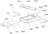
图1是本发明一实施例中冷冻粘连装置的构造示意图;图2是本发明一实施例中冷冻粘连装置的结构示意图一;图3是本发明一实施例中冷冻粘连装置的结构示意图二。1 is a schematic structural diagram of a cryo-adhesion device in an embodiment of the present invention; FIG. 2 is a schematic structural diagram of a cryo-adhesion device in an embodiment of the present invention;
请参考图1至图3,冷冻粘连装置,包括:遥控组件2、阀体组件1、针头导管组件3与气瓶5。Please refer to FIG. 1 to FIG. 3 , the cryo-adhesion device includes: a
所述遥控组件2包括外套结构21与安装于所述外套结构21的遥控器22,所述外套结构21设有用于供所述针头导管组件穿过的导管通道;所述阀体组件1的两端分别连接所述针头导管组件3与所述气瓶5。The
所述外套结构21能够挤压所述针头导管组件3(例如可以是人员实施操控时受控挤压,也可以是外套结构21未被操控时发生挤压),在保持挤压时,所述针头导管组件3能够在所述导管通道内壁与所述针头导管组件1间摩擦力作用下随所述外套结构21一同运动;The
可见,其中的挤压可理解为挤压产生的摩擦力能够使得两者一同运动的挤压,该挤压的形成原理、方式可以是任意的,例如可以是外套结构21至少部分结构发生形变而形成的,也可以是至少部分结构发生运动而形成的。不论何种,均不脱离本实施例的描述。It can be seen that the extrusion can be understood as the extrusion in which the frictional force generated by the extrusion can cause the two to move together. The formation principle and method of the extrusion can be arbitrary. It can also be formed by the movement of at least part of the structure. In any case, it does not deviate from the description of this embodiment.
所述遥控器22用于在被触发时向所述阀体组件1发送触发信号;The
所述阀体组件1用于在接收到所述触发信号时将所述气瓶的气体输送至所述针头导管组件3,以使得所述针头导管组件3能够实施冷冻。The
其中的实施冷冻,可理解为在传输气体的情况下,通过焦耳汤姆逊效应(Joule-Thomson effect)节流产生制冷量,从而将针头导管组件3中针头外部的组织冷冻粘连。The implementation of freezing can be understood as the throttling of the Joule-Thomson effect to generate refrigeration under the condition of transporting gas, thereby freezing and adhering the tissue outside the needle in the
其中的触发信号可以为任意形式和内容的信号,只要阀体组件1能够识别并响应于该信号实施了气体的传输从而实现冷冻,就不脱离本实施例的描述。其可以是通过无线的方式传输,其例如可采用无线的方式传输,但也不完全排除采用有线的方式传输的方案。不论采用何种方式,均可避免手脚共同参与操作,也均可便于单手实现冷冻的控制与导管的推入与抽出。The trigger signal may be a signal of any form and content, as long as the
可见,本实施例所涉及的方案中,由于针头导管组件穿过遥控组件的导管通道,进而,冷冻的控制与导管的推入/抽出均可基于遥控组件实现,进而,可便于操作人员在单手端实现冷冻的控制与导管的推入/抽出,简化了经腔道冷冻粘连术的操作,提高了手术的便利性和安全性。此外,由于未配置脚踏开关等部件,且采用电磁阀的情况下,还可有效节约空间。It can be seen that in the solution involved in this embodiment, since the needle catheter assembly passes through the catheter channel of the remote control assembly, further, the control of freezing and the pushing/extraction of the catheter can be realized based on the remote control assembly, and further, it is convenient for the operator to The hand-end realizes the control of freezing and the push-in/out of the catheter, which simplifies the operation of transluminal cryoadhesion and improves the convenience and safety of the operation. In addition, since there are no components such as foot switches, and a solenoid valve is used, space can be effectively saved.
图4是本发明一实施例中阀体组件的结构示意图;图5是本发明一实施例中电磁阀的截面示意图;图6是本发明一实施例中顶针的结构示意图。4 is a schematic structural diagram of a valve body assembly in an embodiment of the present invention; FIG. 5 is a cross-sectional schematic diagram of a solenoid valve in an embodiment of the present invention; and FIG. 6 is a structural schematic diagram of an ejector pin in an embodiment of the present invention.
请参考图4至图6,所述阀体组件1包括电磁阀11与接收电路板12。Referring to FIGS. 4 to 6 , the
所述电磁阀11包括顶针111、顶针管113、顶针复位部件114、底座112与顶针驱动结构;所述顶针111内设有进气通道1111,所述顶针111穿设于所述顶针管113,所述顶针管113的一端用于连接所述针头导管组件3,另一端连接所述底座112的一侧,所述底座112的另一侧用于连接所述气瓶5;所述顶针111的一端接入所述针头导管组件3。The
所述顶针驱动结构用于在所述接收电路板12接收到所述触发信号时驱动所述顶针111处于进气位置。The ejector pin driving structure is used to drive the
其中的驱动具体可以指:在收到触发信号时,若顶针111处于进气位置,则顶针驱动结构可以驱动其保持处于进气位置,若顶针111未处于进气位置,则顶针驱动结构可以驱动其移动进入进气位置。同时,顶针驱动结构可以是在接收电路板12的控制下实施以上驱动的。The driving may specifically refer to: when the trigger signal is received, if the
其中的进气位置,可理解为:处于所述进气位置的顶针111能够插入所述气瓶5,以使得所述气瓶5中的气体能够进入所述进气通道1111,并经所述进气通道被输送至所述针头导管组件。The intake position can be understood as: the
所述顶针复位部件用于在所述顶针驱动结构未驱动所述顶针111时驱动所述顶针111自所述进气位置复位至非进气位置,处于所述非进气位置的顶针未插入所述气瓶。The ejector pin reset component is used to drive the
进一步的,在气瓶5中,可设有封堵气瓶出口的密封结构(例如后密封结构512),当顶针111进入时,可使得该密封结构不再封堵气瓶出口,进而,顶针111可插入到气瓶5中,获取并传输出其中的气体,当顶针111复位时,该密封结构也可在相应复位部件的驱动下再次封堵气瓶出口。Further, in the
以上所涉及的非进气位置,可理解为是顶针111未插入气瓶,或者未能顶开封堵的任意位置。The non-intake position mentioned above can be understood as any position where the
电磁阀11和/或接收电路板12可以是电池组4供电的,电池组4可以为可充电电池组,进而可卸下单独充电,电池组4也可以非充电电池组。The
在图5所示的实施方式中,顶针111所发生的运动是直线运动,顶针111可沿着顶针管113的轴向移动,在其他可选实施方式中,顶针111所发生的运动也可能是弧线运动、曲线运动等等。In the embodiment shown in FIG. 5 , the movement of the
由于图示的实施方式中采用了电磁阀11,故而,顶针驱动结构可以包括电磁线圈116,其在通电时能够产生所需的电磁力,进而,顶针111会在该电磁力的驱动下发生运动。该电磁线圈116可安装于相应的电磁阀外壳117,该电磁阀外壳117相对于底座112、顶针管113的位置可以是固定的。例如:可利用固定螺母118拧入顶针管113前端外侧的螺纹部,将电磁阀外壳117与底座112相互固定。Since the
在其他可选实施方式中,也不排除采用电磁阀11以外的其他原理的阀设备。In other optional embodiments, valve devices using other principles than the
其中的顶针复位部件,可理解为能够受外部作用力发生形变(例如弯曲、拉升、压缩、弯折等等),并在外部作用力撤去时能够产生复位作用力的任意部件,一种举例中,顶针复位部件可以采用弹簧。在顶针进入进气位置时,该弹簧可以被拉伸或被压缩,进而,当驱动顶针处于进气位置的作用力(例如电磁力)消失时,顶针复位部件可驱动其脱离进气位置,进入非进气位置。The thimble reset component can be understood as any component that can be deformed by external force (such as bending, pulling, compressing, bending, etc.), and can generate reset force when the external force is removed. An example Among them, the thimble reset component can use a spring. When the ejector pin enters the intake position, the spring can be stretched or compressed. Then, when the force (such as electromagnetic force) driving the ejector pin to the intake position disappears, the ejector pin reset part can drive it out of the intake position and enter the non-intake position.
其中一种实施方式中,请参考图5与图6,所述顶针111包括依次连接的第一针段1115、第二针段1116、第三针段1117与第四针段1118,其可如图6中四段不同直径的部分。In one embodiment, please refer to FIG. 5 and FIG. 6 , the
所述第一针段1115插入所述针头导管组件3的进气腔(例如图12所示的进气腔372),同时,第一针段1115与进气腔372之间可实现动态密封,一种举例中,第一针段1115外侧可设有密封圈119,该密封圈119可设于第一针段1115外侧的环形的密封圈槽1114中。The
所述第四针段1118用于插入所述气瓶5;其中,所述第四针段1118的侧壁可设有进气孔1112,所述顶针111插入所述气瓶5时,气体能够自所述进气孔1112进入所述进气通道1111。该进气孔1112的数量、尺寸、排布方式均可以是任意的而不受限于图6所示。The
所述第三针段1117的外径与所述顶针管113的内径相匹配,进而,通过第三针段1117,顶针111沿顶针管113内壁的移动,可实现导向的作用。The outer diameter of the
所述第二针段1116的外径小于所述第三针段1117的外径,所述顶针复位部件114设于第二针段1116的外侧。可见,通过第二针段1116,可为顶针复位部件114的运动提供空间。The outer diameter of the
该些针段的尺寸关系(例如长度的大小、外径的大小等等)可以如图6所示,也可以是其他尺寸关系与形状,只要能满足以上需求,均不脱离本实施例的描述。The dimensional relationship of these needle segments (such as length, outer diameter, etc.) can be as shown in FIG. 6 , or can be other dimensional relationships and shapes, as long as the above requirements can be met, they will not deviate from the description of this embodiment. .
请参考图5,其中一种实施方式中,所述顶针管113的内侧固定设有顶针限位部1131,所述顶针复位部件114连接所述顶针限位部1131,例如,顶针复位部件114为弹簧时,弹簧的一端可连接该顶针限位部1131。Referring to FIG. 5 , in one embodiment, an
所述顶针限位部1131能够阻挡于所述第三针段1117的远离所述气瓶5的一端,所述顶针复位部件1131位于所述第二针段的外侧,以限制所述顶针复位时的运动位置。The
具体的,以图5为例,在电磁力的作用下,顶针1向图示的右方运动,进入进气位置,此时,弹簧可以被压缩,在电磁力消失之后,弹簧可产生一个作用于顶针的向左的作用力,使其向左运动,其运动至极限位置时,第三针段1117的前端可抵住顶针限位部1131,从而被顶针限位部1131限位。Specifically, taking Fig. 5 as an example, under the action of the electromagnetic force, the
具体实施过程中,所述顶针限位部1131包括至少两个扇形限位部,所述至少两个扇形限位部沿所述顶针的周向间隔分布,以在相邻的两个扇形限位部之间形成泄压间隙。In a specific implementation process, the
请参考图6,具体实施过程中,所述第三针段1117设有贯穿两端的泄压槽1113。Referring to FIG. 6 , in the specific implementation process, the
在所述顶针111未插入所述气瓶5时,即其未处于进气位置时,所述进气通道1111的气体能够依次经所述进气孔1112、所述泄压槽1113、所述泄压间隙排出至所述第二针段1116与所述顶针管113的内壁之间的间隔空间,其可形成快速排气的通路的一部分。When the
通过以上电磁阀,可基于顶针实现了气瓶的快速开启和进气的快速泄压,例如:遥控器被按下时可实现冷冻,松开时可排气,实现排气复温。Through the above solenoid valve, the quick opening of the gas cylinder and the quick pressure relief of the intake air can be realized based on the thimble. For example, when the remote control is pressed, it can be frozen, and when it is released, it can be exhausted to realize the exhaust gas rewarming.
请参考图5,其中一种实施方式中,所述第二针段1116的外侧设有顶针外螺纹,所述顶针外螺纹匹配连接限位螺母115,所述顶针复位部件114连接所述限位螺母115;可见,顶针复位部件114为弹簧时,其伸缩方向可以是顶针与顶针管的轴向,且沿该轴向分别连接限位螺母115与顶针限位部1131。Referring to FIG. 5 , in one embodiment, the outer side of the
其中,所述限位螺母115能够通过相对于所述顶针外螺纹的旋转,调整其相对于所述顶针111的位置,以变化所述顶针复位部件114的压缩量或拉伸量。Wherein, the position of the
此外,在图5所示的举例中,电磁力作用下,顶针的运动可使得弹簧被压缩,在其他举例中,例如限位螺母位于弹簧左侧,但固定连接顶针管113,另一固定部固定连接顶针111,且位于弹簧的右侧,此时,电磁力作用下,顶针的运动可使得弹簧被拉伸。不论何种方式,均不脱离本实施例的描述。In addition, in the example shown in FIG. 5, under the action of electromagnetic force, the movement of the thimble can cause the spring to be compressed. In other examples, for example, the limit nut is located on the left side of the spring, but is fixedly connected to the
其中一种实施方式中,请参考图4,所述阀体组件1还包括阀体外壳13,所述电磁阀11与所述接收电路板12设于所述阀体外壳13内。In one embodiment, please refer to FIG. 4 , the
一种举例中,接收电路板12可具有阀体按钮121,阀体按钮121可经阀体外壳13的通孔对外连通,从而适于被操控。该阀体按钮121可作为备用按钮,用于在遥控器无法工作时通过按下该阀体按钮121开启冷冻。In one example, the receiving
阀体外壳13可以包括两个半壳133,该两个半壳可采用卡扣或螺丝进行连接,且合缝处可采取密封措施。The
阀体外壳13还可设有第一排气孔131与第二排气孔132,其可分别视作前排气孔与后排气孔,其可用于引导气体向后排出,具体的,可在气体自第一排气孔131进入内腔后通过第二排气孔132排出至气瓶罩6,例如可经气瓶罩6的尾排气孔(例如图13所示的尾排气孔61)排出,其可用于对回气的排气,也可以用于在停止进气后的快速排气。The
此外,阀体外壳13还可设有遥控器放置槽,进而,遥控组件2或其中的遥控器22可放入阀体外壳13上的遥控器放置槽,另一方案中,遥控组件2或其中的遥控器22也可悬挂或吸附于阀体组件,防止遥控器丢失。In addition, the
以上所涉及的电磁阀和接收电路板的电源可由电池组提供,也可由线缆连接插座实现,进一步的,线缆可直接提供交流电,也可在线缆中配置整流电路,从而将交流电转换为直流电在供应至电磁阀与接收电路板。The power supply of the solenoid valve and the receiving circuit board mentioned above can be provided by the battery pack or by connecting the cable to the socket. Further, the cable can directly provide alternating current, or a rectifier circuit can be configured in the cable to convert the alternating current into DC power is being supplied to the solenoid valve and receiving circuit board.
图7是本发明一实施例中外套结构与遥控器的结构示意图一;图8是本发明一实施例中外套结构的剖面示意图一;图9是本发明一实施例中外套结构与遥控器的结构示意图二;图10是本发明一实施例中外套结构的剖面示意图二。FIG. 7 is a first schematic diagram of the casing structure and the remote control in an embodiment of the present invention; FIG. 8 is a schematic cross-sectional view of the casing structure in an embodiment of the present invention; FIG. 9 is an embodiment of the present invention. Schematic diagram 2 of the structure; FIG. 10 is a schematic
请参考图7至图10,所述外套结构21包括遥控器外套部2106,所述遥控器外套部2106设有触发部件(例如图示的遥控器按钮2104)与用于容置所述遥控器22的遥控器腔2103。所述触发部件能够在被触动时触发所述遥控器腔2103中遥控器22的按钮开关2221。Please refer to FIGS. 7 to 10 , the
通过以上方案,可实现遥控器22相对于外套结构21的容置安装。Through the above solution, the accommodating installation of the
其中一种实施方式中,所述外套结构21还包括通道基体2107。所述导管通道设于所述通道基体2107,所述通道基体2107与所述遥控器外套部2106固定连接。具体的,两者可以是一体的,也可以是装配在一起的。In one embodiment, the
在图7和图8所示的实施方式中,所述通道基体2107中的导管通道包括引导通道2102与挤压通道2101,所述挤压通道2101的内径大于所述引导通道,同时,引导通道2102的内径可大于针头导管组件3中导管的外径;In the embodiment shown in FIG. 7 and FIG. 8 , the conduit channel in the
所述挤压通道2101的内壁能够在所述通道基体2107的相应位置被捏压时发生形变,并挤压所述针头导管组件3。The inner wall of the
所述挤压通道2101的内壁可具有软质粗糙表面,例如,挤压通道2101的内壁可设置有橡胶或硅胶类软质粗糙材料,和/或:所述通道基体2107与所述遥控器外套部2106的相应部位可采用橡胶或硅胶类软质粗糙材料,通过软质粗糙设计,可便于提高与导管之间的摩擦力,从而便于实施操控。The inner wall of the
通过所述引导通道2102,可将导管32向所需方向引导以避免折弯,具体的,引导通道2102的内壁可具有硬质光滑表面,进而,可增加导管32在其中滑动的顺滑性,确保针头导管组件3在其中低阻力移动。Through the
可见,在图7和图8所示实施方式中,可以捏压方式实现对遥控组件2与针头导管组件3的一同运动,在该方式下,整个外套结构21可以是一次性使用的,一种举例中,整个遥控组件2也可以是一次性使用的。It can be seen that in the embodiments shown in FIGS. 7 and 8, the
在图9和图10所示的实施方式中,所述外套结构21还包括按压板2110,所述导管通道包括引导通道2102,如前文所示的,该引导通道2102也设于通道基体2107。In the embodiment shown in FIGS. 9 and 10 , the
所述按压板2110旋转连接所述遥控器外套部2106,例如:遥控器外套部2106和按压板2110可通过转动母关节2108和转动公关节2112实现连接,按压板2110可绕该关节转动一定的角度。The
所述按压板2110的与所述遥控器外套部2106相对的一侧设有挤压槽2111,所述遥控器外套部2106的外表面设有挤压面2109;所述针头导管组件3(例如其导管)能够自所述挤压槽2111与所述挤压面2109之间穿过,并同时穿过所述引导通道2102。The
所述按压板2110用于在被下压发生旋转时通过所述挤压槽2111与所述挤压面2109挤压所述针头导管组件。The
所述挤压面2109和/或所述挤压槽2111的内壁具有软质粗糙表面,例如可采用橡胶或硅胶类的软质粗糙材料。The
同时,与图7和图8所示实施方式类似的,本实施方式中引导通道2102的内壁也可具有前文所涉及的硬质光滑表面。Meanwhile, similar to the embodiment shown in FIG. 7 and FIG. 8 , the inner wall of the
请参考图9与图10,所述外套结构1还包括按压板复位部件2113,所述按压板复位部件2113连接于所述按压板2110与所述遥控器外套部2106之间,用于在所述按压板2110未被下压时驱动所述按压板2110旋转复位,以使得所述针头导管组件不再被挤压。Please refer to FIG. 9 and FIG. 10 , the
一种举例中,按压板复位部件2113可以例如为弹性片,弹性片可放置于设有按压板2110的上弹片槽(未图示)和下弹片槽2105中。In an example, the pressing
以上方案中,将针头导管组件3穿入引导通道2102内,通过手指按下按压板2110,按压板复位部件2113可被压缩,针头导管组件3将被压在挤压槽2111和挤压面2109之间无法移动,此时便可实现针头导管组件3的推入与抽出,松开按压板2110,按压板2110在按压板复位部件2113的弹力作用下可发生复位的旋转(即发生上翘),针头导管组件3(例如其导管32)又恢复自由移动状态。In the above solution, the
在图9和图10所示方案中,自然状态下针头导管组件3可自由移动,按下按压板后针头导管组件3被挤压固定;在其他可选方案中,也可将其配置为自然状态下针头导管组件3被挤压固定,按下按压板后导管可自由移动。In the solutions shown in FIGS. 9 and 10 , the
可见,在其他实施方式中,所述按压板2110用于:在所述按压板2110未被下压时,所述挤压槽2111与所述挤压面2109挤压所述针头导管组件3,所述按压板被下压时,所述挤压槽与所述挤压面不再挤压所述针头导管组件。对应的,按压板复位部件2113用于在所述按压板2110未被下压时驱动所述按压板2110旋转复位,以使得所述针头导管组件3被挤压。It can be seen that in other embodiments, the
具体实施过程中,不论采用何种方式实现挤压,整体外套结构、所述遥控器与所述针头导管组件中至少之一可以为一次性使用的。In the specific implementation process, no matter what method is used to realize the extrusion, at least one of the overall casing structure, the remote control and the needle catheter assembly can be disposable.
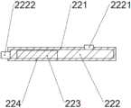
图11是本发明一实施例中遥控器的剖面示意图。11 is a schematic cross-sectional view of a remote controller in an embodiment of the present invention.
请参考图11,遥控器22可以包括发射电路板222、纽扣电池223与遥控器壳221,发射电路板222与纽扣电池223放置于遥控器壳221中,遥控器壳221可安装有电池盖224,纽扣电池223可安装于电池盖224的相应位置,其可用于更换纽扣电池223。Please refer to FIG. 11 , the
发射电路板222可配置有以上所涉及的按钮开关2221,还可配置有保护开关2222,保护开关2222可用于开启和关闭遥控器22的发射电路板,从而使发射电路板222的按钮开关2221被触动后不发生对应的作用,按钮开关2221用于在遥控器按钮2104被按下时被触动,进而,在触动后发射电路板可发出触发信号。该方案中,通过关闭保护开关2222可防止误触遥控器按钮2104(即防止按钮开关2221被误触发)。The transmitting
图12是本发明一实施例中针头导管组件的剖面示意图。12 is a schematic cross-sectional view of a needle catheter assembly in an embodiment of the present invention.
请参考图12,所述针头导管组件3包括依次连接的针头31、导管32与接头结构37,所述导管中设有进气管36,所述接头结构37连接所述阀体组件1,所述接头结构37能够将所述阀体组件1(例如其进气通道1111)输送而来的气体输送至所述进气管36,并经所述进气管36输送至所述针头31,所述导管32穿设于所述导管通道。Please refer to FIG. 12 , the
其中一种实施方式中,所述接头结构37可以包括接头本体375、连接部373与头部管371;所述接头本体375中设有进气腔372;所述连接部373与所述头部管371分别设于所述接头本体375的两端。In one embodiment, the
所述进气腔372用于供所述阀体组件的顶针穿过所述连接部插入,同时,可实现动态密封。所述进气管36穿过所述头部管371连接所述进气腔372。具体的,进气管36放置于整个导管32的内部,且其前端位于针头31前段内部,其后端插入头部管371并固定密封。The
所述连接部373用于对接所述阀体组件中的顶针管113,例如,连接部373包含内螺纹部,其与顶针管113前端的螺纹部相互连接以实现针头导管部件3和阀体部件1之间的连接。The connecting
其中一种实施方式中,为了配合前文所涉及的泄压槽1113、第一排气孔131与第二排气孔132等实现快速排气,所述连接部设有泄压孔374,所述泄压孔374的一端连通至所述顶针111与所述顶针管113的内壁之间的间隔空间,另一端直接或间接连通至阀体组件1中的第一排气孔131;In one of the embodiments, in order to cooperate with the
在所述顶针未插入所述气瓶时,即顶针未处于进气位置时,被排出至所述顶针111与所述顶针管113的内壁之间的间隔空间的气体能够依次经所述泄压孔374、所述第一排气孔131、所述阀体外壳13的内腔排出至所述第二排气孔132,进一步的,可经第二排气孔132排出至气瓶罩6的尾排气孔61,气瓶5可设于气瓶罩6内。When the ejector pin is not inserted into the gas cylinder, that is, when the ejector pin is not in the intake position, the gas discharged into the space between the
其中一种实施方式中,为了实现针头中气体的回气,所述针头导管组件3还包括回气管33与接头外壳38,所述接头结构37可设于所述接头外壳38内,所述接头外壳38设有接头排气孔(未图示),接头排气孔具体可位于接头外壳38内部固定板(图中未示出),所述回气管33连接于所述导管32与所述接头结构37之间,所述回气管33环设于所述进气管外侧,且连通所述导管32与所述进气管36之间的间隔空间,所述回气管33的管壁设有回气孔331。In one embodiment, in order to realize the gas return in the needle, the
其中,返回至所述导管32与所述进气管36之间的间隔空间气体能够依次经所述回气管33、所述回气孔331、所述接头外壳38的内腔、所述接头排气孔、所述第一排气孔131、所述阀体外壳13的内腔排出至所述第二排气孔132,进一步的,可经第二排气孔132排出至气瓶罩6的尾排气孔61,气瓶5可设于气瓶罩6内。The gas returning to the space between the
一种举例中,所述针头导管组件3还可包括前挤压管34与后挤压管35,前挤压管34外套于导管32并通过挤压导管32来实现针头31和导管32的连接密封,后挤压管35外套于导管32并通过挤压导管32来实现回气管33和导管32的连接密封,回气管33后端外套于头部管371并固定密封。In one example, the
一种举例中,所述针头导管组件3还可包括外套于导管32和后挤压管35外的护弯件39,接头外壳38可将护弯软管39和接头结构37的位置固定。In one example, the
此外,以上所涉及的针头导管部件3可以为一次性使用部件,进而,可起到避免交叉感染的效果。In addition, the above-mentioned
其中一种实施方式中,气瓶5可以采用尺寸较小的微型气瓶,进而,可有利于减小占地面积,进一步有利于简化操作过程。可见,电磁阀与微型气瓶连接后可形成一体式的结构,继而,通过电磁阀与微型气瓶的一体式结构,或电磁阀、微型气瓶与电池组的一体式结构,可使腔道冷冻粘连术完全摆脱主机和大气瓶。In one of the embodiments, the
具体实施过程中,气瓶中的气体可选用二氧化碳或一氧化二氮。In the specific implementation process, the gas in the gas cylinder can be selected from carbon dioxide or nitrous oxide.
图13是本发明一实施例中冷冻粘连装置的剖面示意图;图14是本发明一实施例中冷冻粘连装置的使用状态示意图。FIG. 13 is a schematic cross-sectional view of the cryo-adhesion device in an embodiment of the present invention; and FIG. 14 is a schematic view of a use state of the cryo-adhesion device in an embodiment of the present invention.
请参考图13与图14,以下可对一种具体的应用方案进行描述,下文以及前文所涉及的前后(例如前端、后端、向前移动、向后移动等等),可理解为:靠近针头的方向为前,靠近气瓶的方向为后。Please refer to FIG. 13 and FIG. 14 . A specific application scheme can be described below. The following and the front and rear (such as front end, rear end, forward movement, backward movement, etc.) involved in the following can be understood as: The direction of the needle is front and the direction close to the cylinder is rear.
在具体的应用方案中,按下遥控器按钮2104,电磁阀11开启,顶针111将在电磁力的作用下向后移动,弹簧114被压缩,顶针111的后段将插入气瓶出口51内部,顶针111的后段与气瓶5的前密封机构511实现轴向动态密封并将后密封机构512顶开,气瓶5内的气体将依次经进气孔1112、进气通道1111、进气腔372和进气管36到达针头31内部,通过焦耳汤姆逊效应节流产生制冷量,将针头外部的组织冷冻粘连,回气将依次经导管32(具体指导管32与进气管36的间隔空间)、回气管33、回气孔331、接头排气孔、第一排气孔131、阀体外壳13的内腔、后排气孔132和尾排气孔61排出。In a specific application scheme, pressing the
冷冻粘连完成后,松开遥控器按钮2104,电磁阀11关闭,电磁力消失,顶针111将在例如弹簧的顶针复位部件114的作用下向前移动,顶针111的后段(例如第四针段1118)将离开气瓶出口51,后密封机构512瞬间将气瓶出口密封,同时,进气管36和进气通道1111内多余的气体将从进气孔1112排出,以此达到快速排气的目的,使针头31迅速恢复常温,实现与粘连组织的分离。由进气孔1112排出的气体将依次经泄压槽1113、顶针限位部1131的泄压间隙、顶针复位部件所处的间隔空间(即第二针段1116与顶针管113之间的间隔空间)、泄压孔374、第一排气孔131、第二排气孔132和尾排气孔61排出。After the freeze adhesion is completed, release the
在实际使用时,针头导管部件3和外套结构21中的部分或全部可以为一次性使用,气瓶5压力不足时需更换,电池组4电量不足时可更换备用电池组,卸下电池组可单独充电,一种举例中,其余零部件均可重复使用。In actual use, some or all of the
同时,所有左右外壳之间、各部件的外壳之间均设有密封机构,以防止回气或排气从尾排气孔61以外的位置排出。At the same time, a sealing mechanism is provided between all the left and right casings and between the casings of each component to prevent the return air or exhaust gas from being discharged from positions other than the
手术操作中,当内窥镜到达病灶附近后,将针头31插入遥控器部件2并用大拇指和食指捏住遥控器部件2后端两侧,用大拇指和食指挤压挤压通道2101,通过摩擦力固定导管32和遥控器组件2,接下来向前推送针头31,将针头31从内窥镜的钳道插入,松开大拇指和食指,挤压通道2101恢复原形,沿着导管32向后移动遥控器组件,再次通过大拇指和食指的挤压向前推送导管32,如此反复,直至针头31接触病灶,此时,保持挤压通道2101的挤压状态并用同一只手的中指按下遥控器按钮2104,开启冷冻,针头粘连住组织后,继续保持冷冻状态(按住遥控器按钮2104),将病灶组织从气管镜钳道中拉出或与内窥镜一同拉出。拉出病灶组织后,松开中指,停止冷冻,完成取样。During the operation, when the endoscope reaches the vicinity of the lesion, insert the
综上所述,本实施例提供的冷冻粘连装置中,由于针头导管组件穿过遥控组件的导管通道,进而,冷冻的控制与导管的推入/抽出均可基于遥控组件实现,进而,可便于操作人员在单手端实现冷冻的控制与导管的推入/抽出,避免了使用脚踏、主机等,简化了经腔道冷冻粘连术的操作,提高了手术的便利性和安全性。此外,由于未配置脚踏开关等部件,且采用电磁阀的情况下,还可有效节约空间。To sum up, in the cryoadhesion device provided in this embodiment, since the needle catheter assembly passes through the catheter channel of the remote control assembly, the control of freezing and the pushing/extraction of the catheter can be realized based on the remote control assembly, and further, it is convenient to use the remote control assembly. The operator realizes the control of freezing and the push-in/out of the catheter at the one-handed end, avoiding the use of foot pedals, mainframes, etc., simplifying the operation of transluminal cryoadhesion, and improving the convenience and safety of the operation. In addition, since there are no components such as foot switches, and a solenoid valve is used, space can be effectively saved.
最后应说明的是:以上各实施例仅用以说明本发明的技术方案,而非对其限制;尽管参照前述各实施例对本发明进行了详细的说明,本领域的普通技术人员应当理解:其依然可以对前述各实施例所记载的技术方案进行修改,或者对其中部分或者全部技术特征进行等同替换;而这些修改或者替换,并不使相应技术方案的本质脱离本发明各实施例技术方案的范围。Finally, it should be noted that the above embodiments are only used to illustrate the technical solutions of the present invention, but not to limit them; although the present invention has been described in detail with reference to the foregoing embodiments, those of ordinary skill in the art should understand that: The technical solutions described in the foregoing embodiments can still be modified, or some or all of the technical features thereof can be equivalently replaced; and these modifications or replacements do not make the essence of the corresponding technical solutions deviate from the technical solutions of the embodiments of the present invention. scope.
Claims (18)
Priority Applications (7)
| Application Number | Priority Date | Filing Date | Title |
|---|---|---|---|
| CN202010205281.XACN111084658B (en) | 2020-03-23 | 2020-03-23 | Freezing adhesion device |
| JP2022515101AJP7252413B2 (en) | 2020-03-23 | 2020-09-29 | cryoadhesion device |
| EP20927704.5AEP4018949B1 (en) | 2020-03-23 | 2020-09-29 | Cryoadhesion apparatus |
| PCT/CN2020/118706WO2021189800A1 (en) | 2020-03-23 | 2020-09-29 | Cryoadhesion apparatus |
| US17/626,241US12213719B2 (en) | 2020-03-23 | 2020-09-29 | Cryoadhesion apparatus |
| KR1020217030681AKR102631087B1 (en) | 2020-03-23 | 2020-09-29 | cryocoalescence device |
| ES20927704TES2985863T3 (en) | 2020-03-23 | 2020-09-29 | Cryoadhesion apparatus |
Applications Claiming Priority (1)
| Application Number | Priority Date | Filing Date | Title |
|---|---|---|---|
| CN202010205281.XACN111084658B (en) | 2020-03-23 | 2020-03-23 | Freezing adhesion device |
Publications (2)
| Publication Number | Publication Date |
|---|---|
| CN111084658Atrue CN111084658A (en) | 2020-05-01 |
| CN111084658B CN111084658B (en) | 2020-07-24 |
Family
ID=70400688
Family Applications (1)
| Application Number | Title | Priority Date | Filing Date |
|---|---|---|---|
| CN202010205281.XAActiveCN111084658B (en) | 2020-03-23 | 2020-03-23 | Freezing adhesion device |
Country Status (7)
| Country | Link |
|---|---|
| US (1) | US12213719B2 (en) |
| EP (1) | EP4018949B1 (en) |
| JP (1) | JP7252413B2 (en) |
| KR (1) | KR102631087B1 (en) |
| CN (1) | CN111084658B (en) |
| ES (1) | ES2985863T3 (en) |
| WO (1) | WO2021189800A1 (en) |
Cited By (3)
| Publication number | Priority date | Publication date | Assignee | Title |
|---|---|---|---|---|
| WO2021189800A1 (en)* | 2020-03-23 | 2021-09-30 | 上海导向医疗系统有限公司 | Cryoadhesion apparatus |
| CN114159105A (en)* | 2022-01-14 | 2022-03-11 | 上海立升医疗科技有限公司 | Continuous low-temperature biopsy safety gas supply system and low-temperature biopsy device |
| CN114601484A (en)* | 2022-05-13 | 2022-06-10 | 上海导向医疗系统有限公司 | Respiration tracking positioning needle |
Citations (5)
| Publication number | Priority date | Publication date | Assignee | Title |
|---|---|---|---|---|
| US4829999A (en)* | 1987-07-17 | 1989-05-16 | E. R. Squibb And Sons, Inc. | Side mount guidewire gripping device |
| JPH09257150A (en)* | 1996-03-21 | 1997-09-30 | Fuji Koki:Kk | Electromagnetic actuator |
| CN107174297A (en)* | 2017-05-12 | 2017-09-19 | 高建步 | Hand held surgical conduit promotes rifle |
| CN107530116A (en)* | 2015-05-15 | 2018-01-02 | C2治疗公司 | Low temperature balloon ablation system |
| WO2018191013A1 (en)* | 2017-04-11 | 2018-10-18 | Cryterion Medical, Inc. | Pressure control assembly for cryogenic balloon catheter system |
Family Cites Families (19)
| Publication number | Priority date | Publication date | Assignee | Title |
|---|---|---|---|---|
| US5324286A (en)* | 1993-01-21 | 1994-06-28 | Arthur A. Fowle, Inc. | Entrained cryogenic droplet transfer method and cryosurgical instrument |
| US6039730A (en)* | 1996-06-24 | 2000-03-21 | Allegheny-Singer Research Institute | Method and apparatus for cryosurgery |
| US6706037B2 (en) | 2000-10-24 | 2004-03-16 | Galil Medical Ltd. | Multiple cryoprobe apparatus and method |
| US6905496B1 (en)* | 2002-11-01 | 2005-06-14 | Alan G. Ellman | RF electrosurgery cryogenic system |
| JP5121132B2 (en)* | 2005-11-02 | 2013-01-16 | オリンパスメディカルシステムズ株式会社 | Endoscope system and operation assist device for endoscope |
| US8105230B2 (en)* | 2007-07-09 | 2012-01-31 | Olympus Medical Systems Corp. | Medical system |
| EP2590546A4 (en)* | 2010-07-08 | 2014-04-16 | Given Imaging Ltd | Cryo-therapy spray device |
| US20150148791A1 (en)* | 2011-11-05 | 2015-05-28 | Medtronic Ardian Luxemborug S.a.r.l. | Systems, devices and methods for cryogenic renal neuromodulation |
| CN104159534B (en)* | 2012-01-13 | 2017-02-22 | 肌肉科技股份有限公司 | Skin protection for subdermal cryogenic remodeling for cosmetic and other treatments |
| JP6242101B2 (en)* | 2013-07-26 | 2017-12-06 | オリンパス株式会社 | Medical device and system |
| JP6245877B2 (en)* | 2013-07-26 | 2017-12-13 | オリンパス株式会社 | Operation input device for endoscope treatment tool |
| US9468484B2 (en) | 2013-09-13 | 2016-10-18 | Cryofocus Medtech (Shanghai) Co. Ltd. | Automated balloon catheter fluid purging system |
| US10179046B2 (en)* | 2015-08-14 | 2019-01-15 | Edwards Lifesciences Corporation | Gripping and pushing device for medical instrument |
| CN106420039A (en)* | 2016-10-12 | 2017-02-22 | 上海导向医疗系统有限公司 | Cryotherapy system through the natural orifice of the human body |
| WO2018208827A1 (en)* | 2017-05-08 | 2018-11-15 | Crossfire Medical Llc | Catheter systems and methods for ablating varicose veins |
| JP6483768B2 (en) | 2017-07-28 | 2019-03-13 | ニトロ メディカル リミテッド | Apparatus, probe and method for cryogenic system |
| WO2019099878A1 (en) | 2017-11-17 | 2019-05-23 | Cryoconcepts Lp | Portable electro-mechanical cryosurgical device |
| AU2020245381A1 (en)* | 2019-03-25 | 2021-11-04 | Biocompatibles Uk Limited | Cryoprobe |
| CN111084658B (en)* | 2020-03-23 | 2020-07-24 | 上海导向医疗系统有限公司 | Freezing adhesion device |
- 2020
- 2020-03-23CNCN202010205281.XApatent/CN111084658B/enactiveActive
- 2020-09-29USUS17/626,241patent/US12213719B2/enactiveActive
- 2020-09-29ESES20927704Tpatent/ES2985863T3/enactiveActive
- 2020-09-29WOPCT/CN2020/118706patent/WO2021189800A1/ennot_activeCeased
- 2020-09-29KRKR1020217030681Apatent/KR102631087B1/enactiveActive
- 2020-09-29JPJP2022515101Apatent/JP7252413B2/enactiveActive
- 2020-09-29EPEP20927704.5Apatent/EP4018949B1/enactiveActive
Patent Citations (5)
| Publication number | Priority date | Publication date | Assignee | Title |
|---|---|---|---|---|
| US4829999A (en)* | 1987-07-17 | 1989-05-16 | E. R. Squibb And Sons, Inc. | Side mount guidewire gripping device |
| JPH09257150A (en)* | 1996-03-21 | 1997-09-30 | Fuji Koki:Kk | Electromagnetic actuator |
| CN107530116A (en)* | 2015-05-15 | 2018-01-02 | C2治疗公司 | Low temperature balloon ablation system |
| WO2018191013A1 (en)* | 2017-04-11 | 2018-10-18 | Cryterion Medical, Inc. | Pressure control assembly for cryogenic balloon catheter system |
| CN107174297A (en)* | 2017-05-12 | 2017-09-19 | 高建步 | Hand held surgical conduit promotes rifle |
Cited By (4)
| Publication number | Priority date | Publication date | Assignee | Title |
|---|---|---|---|---|
| WO2021189800A1 (en)* | 2020-03-23 | 2021-09-30 | 上海导向医疗系统有限公司 | Cryoadhesion apparatus |
| CN114159105A (en)* | 2022-01-14 | 2022-03-11 | 上海立升医疗科技有限公司 | Continuous low-temperature biopsy safety gas supply system and low-temperature biopsy device |
| CN114601484A (en)* | 2022-05-13 | 2022-06-10 | 上海导向医疗系统有限公司 | Respiration tracking positioning needle |
| CN114601484B (en)* | 2022-05-13 | 2022-11-29 | 上海导向医疗系统有限公司 | breathing tracking needle |
Also Published As
| Publication number | Publication date |
|---|---|
| JP2022547153A (en) | 2022-11-10 |
| KR20210129181A (en) | 2021-10-27 |
| US20230000537A1 (en) | 2023-01-05 |
| US12213719B2 (en) | 2025-02-04 |
| KR102631087B1 (en) | 2024-01-29 |
| EP4018949A1 (en) | 2022-06-29 |
| WO2021189800A1 (en) | 2021-09-30 |
| ES2985863T3 (en) | 2024-11-07 |
| CN111084658B (en) | 2020-07-24 |
| EP4018949A4 (en) | 2023-10-11 |
| JP7252413B2 (en) | 2023-04-04 |
| EP4018949B1 (en) | 2024-07-03 |
Similar Documents
| Publication | Publication Date | Title |
|---|---|---|
| CN111084658B (en) | Freezing adhesion device | |
| AU2007252834B2 (en) | Flexible endoscope system and functionality | |
| US11832795B2 (en) | Fluid control device for endoscope, and endoscope | |
| CN105266754A (en) | Bronchoscope adapter | |
| WO2024093098A1 (en) | Flexible surgical instrument, and flexible instrument and instrument delivery unit thereof | |
| EP2967276A1 (en) | Apparatus for flushing angled window of endoscope | |
| AU2018215070A1 (en) | Mechanisms for controlling rotation of outer cannula for use in endoscopic tool | |
| JP2007244408A (en) | Living tissue resection assisting tool | |
| CN117158875A (en) | Endoscope instrument tube, distal expandable insertion part and endoscope | |
| JP5457649B2 (en) | Medical instrument insertion guide system | |
| CN111166418A (en) | Negative pressure automatic tightening ligature | |
| CN217408787U (en) | Propulsion unit and endoscope of pipe | |
| CN116919320A (en) | Endoscopic instrument switching device and medical robot | |
| CN209269774U (en) | Round Tube Stapler | |
| CN221512027U (en) | Protection type anorectal ligation device | |
| WO2021249331A1 (en) | Clip device capable of being connected in separation and having changeable connection force | |
| CN201263698Y (en) | Hemorrhoid ligation device | |
| CN217927000U (en) | Flexible surgical instrument and connecting mechanism thereof | |
| CN114305531B (en) | Hysteroscope convenient to biopsy forceps operation | |
| CN112075962B (en) | Medical handheld device | |
| CN210933413U (en) | Hemostatic powder propeller | |
| CN221844865U (en) | A continuous hemostatic clip device | |
| CN214632234U (en) | Visible negative pressure ligation anastomat | |
| CN213099762U (en) | A device for intestines and stomach decompression of ileus | |
| CN211433349U (en) | Connector pipe for communicating smoke exhaust pipe of smoke suction scalpel |
Legal Events
| Date | Code | Title | Description |
|---|---|---|---|
| PB01 | Publication | ||
| PB01 | Publication | ||
| SE01 | Entry into force of request for substantive examination | ||
| SE01 | Entry into force of request for substantive examination | ||
| GR01 | Patent grant | ||
| GR01 | Patent grant |