CN1110795C - GMR head, method for its manufacture, and magnetic disc drive utilizing the head - Google Patents
GMR head, method for its manufacture, and magnetic disc drive utilizing the headDownload PDFInfo
- Publication number
- CN1110795C CN1110795CCN98117092ACN98117092ACN1110795CCN 1110795 CCN1110795 CCN 1110795CCN 98117092 ACN98117092 ACN 98117092ACN 98117092 ACN98117092 ACN 98117092ACN 1110795 CCN1110795 CCN 1110795C
- Authority
- CN
- China
- Prior art keywords
- magnetosphere
- magnetic field
- gmr
- magnetic
- locked
- Prior art date
- Legal status (The legal status is an assumption and is not a legal conclusion. Google has not performed a legal analysis and makes no representation as to the accuracy of the status listed.)
- Expired - Fee Related
Links
Images


Classifications
- B—PERFORMING OPERATIONS; TRANSPORTING
- B82—NANOTECHNOLOGY
- B82Y—SPECIFIC USES OR APPLICATIONS OF NANOSTRUCTURES; MEASUREMENT OR ANALYSIS OF NANOSTRUCTURES; MANUFACTURE OR TREATMENT OF NANOSTRUCTURES
- B82Y25/00—Nanomagnetism, e.g. magnetoimpedance, anisotropic magnetoresistance, giant magnetoresistance or tunneling magnetoresistance
- B—PERFORMING OPERATIONS; TRANSPORTING
- B82—NANOTECHNOLOGY
- B82Y—SPECIFIC USES OR APPLICATIONS OF NANOSTRUCTURES; MEASUREMENT OR ANALYSIS OF NANOSTRUCTURES; MANUFACTURE OR TREATMENT OF NANOSTRUCTURES
- B82Y10/00—Nanotechnology for information processing, storage or transmission, e.g. quantum computing or single electron logic
- G—PHYSICS
- G11—INFORMATION STORAGE
- G11B—INFORMATION STORAGE BASED ON RELATIVE MOVEMENT BETWEEN RECORD CARRIER AND TRANSDUCER
- G11B5/00—Recording by magnetisation or demagnetisation of a record carrier; Reproducing by magnetic means; Record carriers therefor
- G11B5/012—Recording on, or reproducing or erasing from, magnetic disks
- G—PHYSICS
- G11—INFORMATION STORAGE
- G11B—INFORMATION STORAGE BASED ON RELATIVE MOVEMENT BETWEEN RECORD CARRIER AND TRANSDUCER
- G11B5/00—Recording by magnetisation or demagnetisation of a record carrier; Reproducing by magnetic means; Record carriers therefor
- G11B5/127—Structure or manufacture of heads, e.g. inductive
- G11B5/33—Structure or manufacture of flux-sensitive heads, i.e. for reproduction only; Combination of such heads with means for recording or erasing only
- G11B5/39—Structure or manufacture of flux-sensitive heads, i.e. for reproduction only; Combination of such heads with means for recording or erasing only using magneto-resistive devices or effects
- G11B5/3903—Structure or manufacture of flux-sensitive heads, i.e. for reproduction only; Combination of such heads with means for recording or erasing only using magneto-resistive devices or effects using magnetic thin film layers or their effects, the films being part of integrated structures
- G11B5/3906—Details related to the use of magnetic thin film layers or to their effects
- G11B5/3945—Heads comprising more than one sensitive element
- G—PHYSICS
- G11—INFORMATION STORAGE
- G11B—INFORMATION STORAGE BASED ON RELATIVE MOVEMENT BETWEEN RECORD CARRIER AND TRANSDUCER
- G11B5/00—Recording by magnetisation or demagnetisation of a record carrier; Reproducing by magnetic means; Record carriers therefor
- G11B5/127—Structure or manufacture of heads, e.g. inductive
- G11B5/33—Structure or manufacture of flux-sensitive heads, i.e. for reproduction only; Combination of such heads with means for recording or erasing only
- G11B5/39—Structure or manufacture of flux-sensitive heads, i.e. for reproduction only; Combination of such heads with means for recording or erasing only using magneto-resistive devices or effects
- G11B2005/3996—Structure or manufacture of flux-sensitive heads, i.e. for reproduction only; Combination of such heads with means for recording or erasing only using magneto-resistive devices or effects large or giant magnetoresistive effects [GMR], e.g. as generated in spin-valve [SV] devices
- G—PHYSICS
- G11—INFORMATION STORAGE
- G11B—INFORMATION STORAGE BASED ON RELATIVE MOVEMENT BETWEEN RECORD CARRIER AND TRANSDUCER
- G11B5/00—Recording by magnetisation or demagnetisation of a record carrier; Reproducing by magnetic means; Record carriers therefor
- G11B5/127—Structure or manufacture of heads, e.g. inductive
- G11B5/33—Structure or manufacture of flux-sensitive heads, i.e. for reproduction only; Combination of such heads with means for recording or erasing only
- G11B5/39—Structure or manufacture of flux-sensitive heads, i.e. for reproduction only; Combination of such heads with means for recording or erasing only using magneto-resistive devices or effects
- G11B5/3903—Structure or manufacture of flux-sensitive heads, i.e. for reproduction only; Combination of such heads with means for recording or erasing only using magneto-resistive devices or effects using magnetic thin film layers or their effects, the films being part of integrated structures
- G11B5/3906—Details related to the use of magnetic thin film layers or to their effects
- G11B5/3929—Disposition of magnetic thin films not used for directly coupling magnetic flux from the track to the MR film or for shielding
- Y—GENERAL TAGGING OF NEW TECHNOLOGICAL DEVELOPMENTS; GENERAL TAGGING OF CROSS-SECTIONAL TECHNOLOGIES SPANNING OVER SEVERAL SECTIONS OF THE IPC; TECHNICAL SUBJECTS COVERED BY FORMER USPC CROSS-REFERENCE ART COLLECTIONS [XRACs] AND DIGESTS
- Y10—TECHNICAL SUBJECTS COVERED BY FORMER USPC
- Y10S—TECHNICAL SUBJECTS COVERED BY FORMER USPC CROSS-REFERENCE ART COLLECTIONS [XRACs] AND DIGESTS
- Y10S977/00—Nanotechnology
- Y10S977/902—Specified use of nanostructure
- Y10S977/932—Specified use of nanostructure for electronic or optoelectronic application
- Y10S977/933—Spintronics or quantum computing
- Y10S977/934—Giant magnetoresistance, GMR
Landscapes
- Engineering & Computer Science (AREA)
- Chemical & Material Sciences (AREA)
- Nanotechnology (AREA)
- Manufacturing & Machinery (AREA)
- Crystallography & Structural Chemistry (AREA)
- Physics & Mathematics (AREA)
- Mathematical Physics (AREA)
- Theoretical Computer Science (AREA)
- Hall/Mr Elements (AREA)
- Magnetic Heads (AREA)
Abstract
Translated fromChineseDescription
Translated fromChinese技术领域technical field
本发明一般地涉及一种GMR磁头、一种制造这种GMR磁头的方法及使用该GMR磁头的磁盘驱动器。The present invention generally relates to a GMR head, a method of manufacturing the GMR head, and a disk drive using the GMR head.
背景技术Background technique
在20世纪90年代,磁盘上信息的位密度得到极大提高:每十年提高了100倍。如果今后保持这个速度发展下去,到2000或2001年位密度将达到10G位/平方英寸。从近来巨磁阻(GMR)磁头技术的发展来看会实现这个目标。In the 1990s, the bit density of information on magnetic disks increased enormously: by a factor of 100 per decade. If this speed is maintained in the future, the bit density will reach 10G bit/square inch by 2000 or 2001. Judging by the recent development of giant magnetoresistance (GMR) head technology, this goal will be achieved.
图1显示了在磁盘驱动器中使用GMR磁头的复合磁头112的整体布置,磁介质114如磁盘正对着复合磁头112放置。此处显示的复合磁头112是具有背负式(piggy backed)结构的归并型磁头,它包括一个写头118和一个读头116,其中写头118位于读头116的背面,读头116的上部屏蔽层120同时作为写头118的底部写入磁体120(底层磁芯)。FIG. 1 shows the overall arrangement of a composite
图1中GMR磁头100包含在读头116中。该GMR磁头包括GMR薄膜122、一对电极124a和124b、分别放置在电极对对立面的底部读屏蔽层98和上部读屏蔽层120。The GMR
写头118包括写线圈128、围绕写线圈128的有机绝缘层130、磁间隔膜132、置于有机绝缘层130和磁间隔膜132上面的上部写磁极134以及置于有机绝缘层130和磁间隔膜132下面的底部写入磁极120。The
图2显示了GMR磁头100的整体布置。如图2所示,该GMR磁头100包括一个旋转阀膜(spin valve film)122,旋转阀膜122包括形成于衬底101上的自由磁层102、中间层103、被锁定磁层104和反铁磁层或抑制层105,衬底101包含形成于底部读屏蔽层(没有画出)上的底部间隔膜(没有画出)。GMR磁头100包括旋转阀膜122和最好至少与旋转阀膜122的自由磁层102相应端部相连的一对电极124a和124b(图1中所示)。FIG. 2 shows the overall arrangement of the GMR
图3A-D说明旋转阀膜122的电阻如何随着其中磁场强度改变而变化。如图3A所示,旋转阀膜122有4层。磁层(自由和被锁定)102和104由中间的非磁性层103分开。被锁定磁层104上面是反铁磁层105,因此在退火后,与反铁磁层105邻接的层104中的磁场强度Mp方向被锁定为与反铁磁层105的边界或交界区域处磁场强度方向一致。3A-D illustrate how the resistance of the
另一方面,由中间层103隔开的自由磁层102磁场强度方向不固定。换句话说,被锁定磁层104具有高的矫顽力或抗磁力,而自由磁层102具有低的矫顽力或抗磁力,如图3C所示。On the other hand, the direction of the magnetic field strength of the free
在外部磁场影响下,自由磁层102被磁化为与外部磁场方向一致,在一个方向获得某一磁场强度Mf。众所周知,当自由磁层102和被锁定磁层104的磁场强度方向成180°角(即它们指向相反的方向如图3A所示)时,旋转阀膜的电阻达到最大值。Under the influence of the external magnetic field, the free
图4A和4B说明了GMR磁头所依据的原理。如图4A所示,如果自由磁层102和被锁定磁层104磁场强度方向相反,那么当电子由一层运动到另一层中时,相对较多数目的电子可能被中间层(无磁层)和磁层的交界层散射,从而表现出高的电阻率。Figures 4A and 4B illustrate the principle on which the GMR head is based. As shown in Figure 4A, if the free
如果如图4B所示,自由磁层102的磁场强度方向和被锁定磁层104的方向一致时,通过中间层(无磁性)和磁层的交界层时只有相对较少数目的电子被散射。进一步解释为,每个运动电子或者旋转加速或旋转减慢,但是其中的一个受到给定磁场作用散射较为严重。图4A和4B中,电子已经发生了散射,但是图4B所示的散射情形比图4A所示的散射情形发生的可能性要小一些,因而可以控制电子从被锁定磁层104流入自由磁层103。If, as shown in FIG. 4B , the direction of the magnetic field strength of the free
如图3D所示,具有旋转阀结构的GMR元件的自由磁层中磁场强度Mf随外加磁场而变化,在此例中所示的代表性信号是磁场Hsig。磁场强度的变化反过来会导致GMR元件的旋转阀膜122电阻变化,这与自由磁层102磁场强度Mf和被锁定磁层104磁场强度Mp的夹角θ的余弦成比例,θ为0°-180°。As shown in Figure 3D, the magnetic field strength Mf in the free magnetic layer of the GMR element with a spin valve structure varies with the applied magnetic field, and the representative signal shown in this example is the magnetic field Hsig. The variation of the magnetic field strength can cause the resistance change of the rotating
相应地,使用这种GMR膜122的磁头中,在没有外加磁场作用时,自由磁层102中磁场强度Mf与被锁定磁层104中磁场强度Mp相垂直(90°),在外加磁场(如信号磁场Hsig)作用下时,在0°到180°范围内电阻将基本上呈线性对称地变化,并且在θ=90°时具有平均值。电阻的对称响应使得容易处理来自磁盘驱动器的读信号。Correspondingly, in the magnetic head using this GMR
然而,在实际旋转阀元件中,自由磁层102不仅受外加信号磁场Hsig的影响,而且还受一些噪声场的影响,噪声场由很多因素造成例如自由磁层102和被锁定磁层104中磁场的交换耦合、被锁定磁层104端面呈现出的磁极产生的磁场以及流过GMR元件的检测电流产生的磁场。结果造成层102中的磁场强度偏离X方向(沿元件宽度方向),从而引起元件电阻变得基本上是非线性和非对称的。However, in an actual rotary valve element, the free
为了使自由磁层102中的磁场强度Mf在没有外加磁场时定向为X轴方向(沿层的宽度方向),需要施加一个称为偏置磁场的附加磁场以抵消噪声场的Y分量。In order to orient the magnetic field strength Mf in the free
偏置磁场依赖于噪声场的幅度和方向。GMR磁头元件最好设计得使该偏置磁场的所需值减小。The bias magnetic field depends on the magnitude and direction of the noise field. The GMR head element is preferably designed such that the required value of the bias field is reduced.
另一方面,GMR磁头的宽度w(即Z轴方向)由相应磁记录介质的记录位密度决定,因而旋转阀元件在磁记录介质上可能覆盖一个磁道(图1)并且准确读取介质上所存储的位数据。因此对于位密度大的记录磁介质GMR磁头的宽度必须具有足够的小尺寸。On the other hand, the width w (that is, the Z-axis direction) of the GMR head is determined by the recording bit density of the corresponding magnetic recording medium, so the rotary valve element may cover one track on the magnetic recording medium (Fig. Stored bit data. Therefore, the width of the GMR head must be sufficiently small for a recording medium with a high bit density.
需说明的是如果元件高度h(Y方向大小)比宽度小的多,那么自由层102中的磁场强度Mf趋向于被锁定在纵向(X方向)。It should be noted that if the element height h (size in the Y direction) is much smaller than the width, then the magnetic field strength Mf in the
因此,最好使高度h等于或小于宽度w。另外为了保证信号磁场Hsig进入整个元件也最好使高度h小于宽度w,否则信号磁场Hsig不能穿透元件Y方向。Therefore, it is better to make the height h equal to or smaller than the width w. In addition, in order to ensure that the signal magnetic field Hsig enters the entire component, it is better to make the height h smaller than the width w, otherwise the signal magnetic field Hsig cannot penetrate the Y direction of the component.
在实际使用的大小为几微米×几微米的旋转阀元件中,如果随着介质比特密度增加高度h减小,那么被锁定磁层104和自由磁层102磁场强度的静止磁耦合(负交换耦合)对于校准自由磁层102中与被锁定磁层104磁场强度反方向平行的磁场强度Mf就起着较为重要的作用,从而难于找到合适偏置点。In the practically used rotary valve element with a size of several micrometers × several micrometers, if the height h decreases as the medium bit density increases, the static magnetic coupling (negative exchange coupling) of the magnetic field strength of the locked
另一方面,如果只减小GMR元件的宽度,高度保持不变,那么自由磁层102中靠近磁记录介质的区域处磁场强度随外加信号磁场Hsig而旋转,而远离磁介质的区域处磁场强度不随Hsig旋转因此电阻不发生改变。结果GMR元件的远距离区域对读取信号贡献很小,因此磁头整体读灵敏度降低。On the other hand, if only the width of the GMR element is reduced and the height remains unchanged, then the magnetic field strength at the region close to the magnetic recording medium in the free
为了实现更高位密度,GMR元件尺寸一方面要尽量小,另一方面为了找到合适的偏置磁场其高度要足够大。因此,作为第二个最好的选择,给定较小的GMR元件高度,为了找到最佳偏置点可以试图在一个方向提供最小检测电流以消除噪声磁场。然而,检测电流总有一定限制,因此单独由检测电流产生偏置磁场进行改进不会彻底解决问题。In order to achieve a higher bit density, the size of the GMR element should be as small as possible on the one hand, and its height should be large enough to find a suitable bias magnetic field on the other hand. Therefore, as a second best option, given the small GMR element height, one can try to provide the minimum sense current in one direction to cancel the noise magnetic field in order to find the best bias point. However, the detection current is always limited, so the improvement of the bias magnetic field generated solely by the detection current will not completely solve the problem.
一种选择是,可以减小被锁定磁层104的厚度从而降低对自由磁层中磁场强度的磁场影响。然而,不推荐使用这种方法,因为被锁定磁层104必须有一最小厚度保证使其磁场强度被锁定,结果使得不能随意减小磁化。As an option, the pinned
另一种选择是,在自由磁层102和被锁定磁层104间插入一个薄的中间层(非磁层)103来加强两个磁层间的铁磁耦合以补偿静态磁耦合。中间层厚度必须最多为10埃,因而这是不实用的。Another option is to insert a thin intermediate layer (non-magnetic layer) 103 between the free
具有双旋转阀结构的GMR元件具有较大的磁阻效应从而读灵敏度提高,这在后面第三个实例中将详细叙述。然而,具有两个被锁定磁层的元件也呈现出从那里漏泄的较大磁通量而影响自由磁层中的磁场强度。在此情况下,漏泄磁场不能通过上述方法消除或抑制。The GMR element with double rotary valve structure has a larger magnetoresistive effect, thereby improving read sensitivity, which will be described in detail in the third example later. However, elements with two pinned magnetic layers also exhibit a larger magnetic flux leaking therefrom to affect the magnetic field strength in the free magnetic layer. In this case, the leakage magnetic field cannot be eliminated or suppressed by the above-mentioned method.
发明内容Contents of the invention
如上所述,必须找到一种基本上将偏置磁场减少到所需水平的新的方法。As mentioned above, a new method must be found to substantially reduce the bias magnetic field to the desired level.
本发明的一个目的是提供一种新的没有漏磁场的GMR磁头。SUMMARY OF THE INVENTION An object of the present invention is to provide a new GMR magnetic head free of leakage field.
本发明的另一个目的是提供一种通过减小由GMR磁头的被锁定磁层在自由磁层中产生的静态磁场可以关于一个适当设置的偏置点动作的GMR磁头。Another object of the present invention is to provide a GMR magnetic head which can operate about a suitably set bias point by reducing the static magnetic field generated in the free magnetic layer by the pinned magnetic layer of the GMR magnetic head.
本发明进一步目的是提供一种新GMR磁头的制造方法。A further object of the present invention is to provide a method of manufacturing a new GMR magnetic head.
本发明再进一步目的是提供一种通过减小由其被锁定磁层在自由磁层中产生的静态磁场而可以在合适设置的偏置点动作的GMR磁头的制造方法。A still further object of the present invention is to provide a method of manufacturing a GMR magnetic head capable of operating at a properly set bias point by reducing the static magnetic field generated in the free magnetic layer by its pinned magnetic layer.
本发明再进一步目的是提供使用任一种上述GMR磁头的磁盘驱动器。A still further object of the present invention is to provide a disk drive using any of the above GMR heads.
依照本发明的一个方面,提供一种GMR磁头,包括:According to one aspect of the present invention, a kind of GMR magnetic head is provided, comprising:
包含GMR元件的检测部分,和a detection section containing a GMR element, and
独立设置在所述元件高度方向一侧的磁场矫正部分,其中The magnetic field correction part independently arranged on one side of the height direction of the element, wherein
所述检测部分至少包括自由磁层、中间层和被锁定磁层,The detection part includes at least a free magnetic layer, an intermediate layer and a locked magnetic layer,
所述磁场矫正部分至少包括设置在所述元件高度方向一侧的独立的磁层,由此减小了所述被锁定磁层在所述自由磁层中产生的磁场。The magnetic field rectifying portion includes at least an independent magnetic layer disposed on one side in the height direction of the element, thereby reducing a magnetic field generated by the locked magnetic layer in the free magnetic layer.
依照本发明的另一个方面,提供一种磁头,包括:According to another aspect of the present invention, a magnetic head is provided, comprising:
包含GMR元件的检测部分;和a detection portion comprising a GMR element; and
设置在所述元件高度方向一侧的独立的磁场矫正部分,其中An independent magnetic field rectification part arranged on one side of the height direction of the element, wherein
所述检测部分至少包括一个自由磁层、中间层和被锁定磁层的组合,The detection part includes at least a combination of a free magnetic layer, an intermediate layer and a locked magnetic layer,
所述磁场矫正部分结构与检测部分相同。The structure of the magnetic field correction part is the same as that of the detection part.
应当指出,磁场矫正部分和检测部分有相同的结构并且在GMR元件高度方向并排放置。因而磁场矫正膜可以较容易与传感器膜一起形成。It should be noted that the magnetic field correction section and the detection section have the same structure and are placed side by side in the height direction of the GMR element. Thus the magnetic field correcting film can be formed more easily together with the sensor film.
本发明中被锁定磁层比自由磁层长,减少了被锁定磁层对自由磁场层中磁化强度的影响,从而减小了偏置磁场。In the present invention, the locked magnetic layer is longer than the free magnetic layer, which reduces the influence of the locked magnetic layer on the magnetization in the free magnetic layer, thereby reducing the bias magnetic field.
在这种旋转阀结构中,被锁定磁层对自由磁层的磁层影响小的多。因而,自由磁层与很少被锁定磁层磁层反向平行对齐。因此,如果没有外加信号磁场,自由磁层中的磁场强度可以置为基本与被锁定磁层中的磁场强度垂直。In this spin valve structure, the locked magnetic layer has much less influence on the magnetic layer of the free magnetic layer. Thus, the free magnetic layer is aligned antiparallel to the few locked magnetic layers. Therefore, if no signal magnetic field is applied, the magnetic field strength in the free magnetic layer can be set substantially perpendicular to the magnetic field strength in the pinned magnetic layer.
本发明的原理可以应用于下面所述的各种类型的GMR磁头。The principles of the present invention can be applied to various types of GMR heads as described below.
所述检测部分除了包括所述自由磁层、中间层和被锁定磁层外,还包括反铁磁层。In addition to the free magnetic layer, the intermediate layer and the locked magnetic layer, the detection part also includes an antiferromagnetic layer.
所述检测部分具有包括以下列顺序在衬底上依次沉积的所述自由磁层、中间层、被锁定磁层和反铁磁层的单旋转阀结构。The detecting portion has a single spin valve structure including the free magnetic layer, intermediate layer, pinned magnetic layer, and antiferromagnetic layer sequentially deposited on a substrate in the following order.
所述检测部分具有包括以下列顺序在衬底上依次沉积的所述反铁磁层、被锁定磁层、中间层和自由磁层的反单旋转阀结构。The detecting portion has an inverse single spin valve structure including the antiferromagnetic layer, pinned magnetic layer, intermediate layer, and free magnetic layer sequentially deposited on a substrate in the following order.
所述检测部分具有至少包括以下列顺序在衬底上依次沉积的所述第一被锁定磁层、第一中间层、自由磁层、第二中间层和第二被锁定磁层的双旋转阀结构。The detection section has a double rotary valve including at least the first locked magnetic layer, the first intermediate layer, the free magnetic layer, the second intermediate layer and the second locked magnetic layer sequentially deposited on the substrate in the following order structure.
所述检测部分具有至少包括以下列顺序在衬底上依次沉积的所述第一反铁磁层、第一被锁定磁层、第一中间层、自由磁层、第二中间层、第二被锁定磁层和第二反铁磁层的双旋转阀结构。The detection part has at least the first antiferromagnetic layer, the first pinned magnetic layer, the first intermediate layer, the free magnetic layer, the second intermediate layer, the second Dual spin-valve structure with locked magnetic layer and second antiferromagnetic layer.
所述检测部分具有包括多个层组合的超格子GMR元件,其中每一个组合具有自由磁层、中间层和被锁定磁层,并且相邻组合被非磁性层隔开。The detection section has a superlattice GMR element comprising a plurality of layer combinations, each combination having a free magnetic layer, an intermediate layer and a locked magnetic layer, and adjacent combinations are separated by a nonmagnetic layer.
在每一个这些GMR磁头中,为了使磁场矫正部分能够正常工作,检测部分和磁场矫正部分在磁头高度方向最好分开,且相距不超过0.1微米,理想距离为不超过0.01微米。In each of these GMR heads, in order for the magnetic field correction part to work normally, the detection part and the magnetic field correction part are preferably separated in the height direction of the head, and the distance is no more than 0.1 micron, ideally the distance is no more than 0.01 micron.
依照本发明的另一方面,提供了一种制造GMR磁头的方法,包括:According to another aspect of the present invention, there is provided a method of manufacturing a GMR magnetic head, comprising:
至少依次在衬底上沉淀自由磁层、在所述自由磁层上沉淀中间层、在所述中间层上沉淀被锁定磁层和在所述被锁定磁层上沉淀反铁磁层形成旋转阀膜;以及At least sequentially depositing a free magnetic layer on the substrate, depositing an intermediate layer on the free magnetic layer, depositing a locked magnetic layer on the intermediate layer, and depositing an antiferromagnetic layer on the locked magnetic layer to form a spin valve film; and
在所述旋转阀膜的中间高度处将其分隔开。The rotary valve membrane is separated at its mid-height.
在这种GMR磁头中,在旋转阀膜高度方向的中间位置将其分离的步In this GMR head, the step of separating it at the middle position in the height direction of the rotary valve film
依照本发明的又一个方面,提供一种磁头,包括:According to yet another aspect of the present invention, a magnetic head is provided, comprising:
独立放置在用于检测外加磁场的检测部分中的GMR元件高度方向的一侧的磁层,所述磁层被锁定磁化为与所述检测部分的被锁定磁层的被锁定磁层的磁场相同的方向。A magnetic layer independently placed on one side of the height direction of the GMR element in the detection section for detecting an applied magnetic field, the magnetic layer is locked and magnetized to be the same magnetic field as the locked magnetic layer of the detection section direction.
与检测外加磁场变化的检测部分并排分离设置的磁场矫正部分,所述磁场矫正部分与所述检测部分具有相同的层状结构;其中所述检测部分的被锁定磁层和所述磁场矫正部分的磁层具有相同的磁化方向。A magnetic field correction part arranged side by side with a detection part for detecting changes in an applied magnetic field, the magnetic field correction part having the same layered structure as the detection part; wherein the locked magnetic layer of the detection part and the magnetic field correction part The magnetic layers have the same magnetization direction.
附图说明Description of drawings
本发明前述的和其他的目的及优点将清楚地显示在结合附图对优选实施方案的详细描述中,附图中同一标号表示同一部分,其中:The foregoing and other objects and advantages of the present invention will be clearly shown in the detailed description of the preferred embodiments in conjunction with the accompanying drawings, in which the same reference numerals represent the same parts, wherein:
图1是GMR磁头和磁盘组合的主要部分的示意图;Fig. 1 is the schematic diagram of the main part of GMR magnetic head and disk combination;
图2用于说明旋转阀元件;Figure 2 is used to illustrate the rotary valve element;
图3用于说明旋转阀元件的运行;Figure 3 is used to illustrate the operation of the rotary valve element;
图4用于说明旋转阀中观察到的巨磁阻效应;Figure 4 is used to illustrate the giant magnetoresistance effect observed in the rotary valve;
图5显示了具有本发明单旋转阀结构的典型GMR元件;Figure 5 shows a typical GMR element with a single rotary valve structure of the present invention;
图6显示了具有图5所示单旋转阀结构的被锁定磁层中的磁场强度;Figure 6 shows the magnetic field strength in the locked magnetic layer with the single spin valve structure shown in Figure 5;
图7是用于计算GMR元件自由磁层中磁场分布的单旋转阀结构模型横截面;Fig. 7 is a cross-section of a single rotary valve structure model used to calculate the magnetic field distribution in the free magnetic layer of a GMR element;
图8是计算出的图5所示单旋转阀结构中自由磁层的磁场分布曲线图;Fig. 8 is a calculated magnetic field distribution curve of the free magnetic layer in the single-rotation valve structure shown in Fig. 5;
图9是具有反单旋转阀结构的GMR元件的横截面;Figure 9 is a cross-section of a GMR element with an inverted single rotary valve structure;
图10是具有双旋转阀结构GMR元件的横截面;Figure 10 is a cross-section of a GMR element with a double rotary valve structure;
图11是计算出的图10所示双旋转阀结构中自由磁层磁场分布曲线图;Fig. 11 is the calculated free magnetosphere magnetic field distribution curve in the double rotary valve structure shown in Fig. 10;
图12显示了图7所示GMR元件的自由磁层中磁化状态;Figure 12 shows the state of magnetization in the free magnetic layer of the GMR element shown in Figure 7;
图13显示了图10所示GMR元件的自由磁层中磁化状态;Figure 13 shows the state of magnetization in the free magnetic layer of the GMR element shown in Figure 10;
图14是具有超格子结构的GMR元件的横截面;Fig. 14 is the cross-section of the GMR element with superlattice structure;
图15是制造如图7所示GMR元件过程的流程图;Fig. 15 is a flowchart of the process of manufacturing the GMR element shown in Fig. 7;
图16是用如图5、9或10所示GMR元件中的任意一种制造的磁盘驱动器主要部分的平面图;Fig. 16 is a plan view of the main part of a disk drive manufactured with any one of the GMR elements shown in Fig. 5, 9 or 10;
具体实施方式Detailed ways
本发明将结合附图以实施例来说明四个优选GMR元件、使用该元件的GMR磁头的制造方法和磁驱动器,所有图中相同标号代表相同或相应元件,为了简短起见,详细描述将不再重复。The present invention will illustrate four preferred GMR elements, the manufacturing method of the GMR magnetic head that uses this element and the magnetic driver with embodiment in conjunction with accompanying drawing, and the same reference numeral represents identical or corresponding element among all figures, for the sake of brevity, detailed description will no longer repeat.
本发明的原理具体体现在下面所述的GMR元件中,其中第二磁层设置为与磁头检测部分的第一被锁定磁层侧面相连并且设在其上面的位置。第二磁层被磁化为与第一被锁定磁层方向相同,以减小从第一被锁定磁层进入自由磁层的磁场的影响,从而为自由磁层提供了好的偏置点。下面,通过第一到第四个本发明的实施方案对本原理进行详细描述。The principle of the present invention is embodied in the GMR element described below, wherein the second magnetic layer is provided in a position adjacent to and above the first pinned magnetic layer of the head detecting portion. The second magnetic layer is magnetized in the same direction as the first pinned magnetic layer to reduce the effect of the magnetic field entering the free magnetic layer from the first pinned magnetic layer, thereby providing a good bias point for the free magnetic layer. Hereinafter, this principle will be described in detail through the first to fourth embodiments of the present invention.
[GMR头][GMR head]
(实施例1)(Example 1)
图5说明了第一个GMR元件的结构。把这个GMR称为单旋转阀GMR元件(以下称为单旋转阀元件),因为它具有一个不同于图10所示旋转阀膜中双结构的单结构检测部分10。Figure 5 illustrates the structure of the first GMR element. This GMR is called a single rotary valve GMR element (hereinafter referred to as a single rotary valve element) because it has a single structure detecting portion 10 different from the double structure in the rotary valve diaphragm shown in FIG. 10 .
如图5所示,单旋转阀元件具有形成在衬底11上的检测部分10和磁场矫正部分20。这个元件不同于现有技术典型旋转阀元件之处在于它包含磁场矫正部分20。As shown in FIG. 5 , the single-rotation valve element has a detection portion 10 and a magnetic field correction portion 20 formed on a
检测部分10包括衬底11、形成于衬底11上的自由磁层(常称为自由层)12、形成于自由层11上的非磁层中间层13、形成于中间层13上的被锁定磁层(常称为被锁定层)14和形成于被锁定层14上的反铁磁层(也称为锁定层)15。The detection part 10 includes a
反铁磁层15用于把相连的被锁定磁层14的磁场强度固定或锁定在被锁定方向。如果没有反铁磁层15,在外加磁场的作用下被锁定磁层14中磁化状态可能会改变方向。然而,如果用硬磁材料制造被锁定磁层14则其中的磁化方向会非常固定而不需要反铁磁层15。但是,总的来说,使用反铁磁层15的优点在于可以使GMR元件的磁化稳定。The antiferromagnetic layer 15 is used to fix or lock the magnetic field strength of the connected locked
在讨论GMR元件的构造时,使用了直角坐标系,其中X轴定义为正对GMR磁头空气支承表面(ABS)的磁道的宽度方向,Y定义为GMR元件高度方向,即远离ABS的方向,Z轴定义为垂直磁层方向即沿着磁道方向,在检测部分10和磁场矫正部分20间是间隙或空隙g。典型检测部分10的宽度w=0.3微米,高度h=0.3微米,空隙g=0.01微米。When discussing the construction of the GMR element, a Cartesian coordinate system is used, where the X-axis is defined as the width direction of the track facing the GMR head air bearing surface (ABS), and Y is defined as the height direction of the GMR element, that is, the direction away from the ABS, Z The axis is defined as the direction perpendicular to the magnetic layer, ie along the track, and between the detection portion 10 and the magnetic field correction portion 20 is the gap or gap g. A typical detection portion 10 has a width w=0.3 microns, a height h=0.3 microns, and a gap g=0.01 microns.
此处所示例子中,上述各种元件的构成如下。In the example shown here, the above-mentioned various components are configured as follows.
衬底11有一形成于下部读屏蔽层(图1)上的下部绝缘间隙膜,其上涂敷约50埃厚的钽为底层以在绝缘膜上形成平整表面。
图5中所示自由磁层12看上去为单层,实际上是由两层组成,一层为约40埃厚的铁镍合金(CoFe)薄膜,另一层为约25埃厚的钴铁合金薄膜。The free
非磁层中间层13是厚度约为24埃厚的磁铜薄膜。The
被锁定磁层14是钴铁合金薄膜,组成与自由磁层12相同,厚度为22埃。The pinned
反铁磁层15是250埃厚的钯铂锰合金(PdPtMn)薄膜。The antiferromagnetic layer 15 is a thin film of palladium-platinum-manganese alloy (PdPtMn) with a thickness of 250 angstroms.
磁场矫正部分20可以与衬底11具有相同的结构。必须指出,实施本发明的必要元件为对应于检测部分10的被锁定磁层14的磁层24。其他元件不是必须的。其中所示单旋转阀元件的磁场矫正部分20与衬底11具有相同的结构,这仅仅是为了使它可以容易地和同时地用与检测部分10相同的制造工艺制造。The magnetic field correction part 20 may have the same structure as the
尽管示范的磁场矫正部分20与衬底11具有相同的结构,磁场矫正部分20中“自由”层和“被锁定”层是不相关地,因此不相关的层用材料名称表示而没用功能名称“自由”和“被锁定”。Although the exemplary magnetic field rectifying portion 20 has the same structure as the
因而磁场矫正部分20包括形成于与检测部分10同一衬底11上的磁层22、形成于磁层22上的非磁性中间层23、形成于非磁层23上的磁层24和形成于磁层24上的反铁磁层25,它们以上述顺序形成。其组成、厚度和每层外部尺寸可以与检测部分10的相应部件相同。Thus the magnetic field correcting portion 20 includes a
图6说明了检测部分10中被锁定磁层14的磁场强度Mp是如何形成的。一般被锁定磁层14中磁场强度Mp被磁化被锁定为如图6中实箭头所示Y轴方向。磁场强度的被锁定在制造被锁定磁层的最后阶段通过在外加磁场作用下首先对反铁磁层15进行热处理来完成。由于相互磁交换作用或磁交换耦合,反铁磁层15下面的被锁定磁层14中磁场强度被锁定为与反铁磁层边界或交界面处磁场强度相同。FIG. 6 illustrates how the magnetic field strength Mp of the pinned
如上所述,磁场矫正部分20与检测部分10具有相同的结构并通过相同的工艺制造,因此与被锁定磁层14对应的磁层24中磁场强度Mp′同被锁定磁层14中磁场强度Mp方向相同。然而,应当明白,磁层24在制造过程中不需要磁化。磁场强度Mp′仅仅是同时制造两个层14和24的自然结果,当如图6所示的磁层14中磁场强度Mp被锁定时会趋向于锁定磁层24。As mentioned above, the magnetic field correction part 20 has the same structure as the detection part 10 and is manufactured by the same process, so the magnetic field strength Mp' in the
检测部分10的自由磁层12设置为其磁畴方向在与被锁定磁层14磁场强度Mp(图中虚线所示)成90°的X轴方向。然而,磁畴仅被微弱的限制在该方向,磁场强度Mf在外部干扰下很容易改变方向。即被锁定磁层14具有非常高的被锁定力或矫顽力,而自由磁层12具有非常低的被锁定力或矫顽力。The free
因此,GMR元件受来自磁盘(没画出)的外加信号磁场Hsig作用,磁场强度Mf在磁场作用下旋转。自由磁层12中磁场强度Mf和被锁定磁层14中磁场强度Mp夹角θ为180°时,旋转阀膜的电阻达到最大值。当θ为零时,电阻达到最小值。电阻与θ的余弦成正比。Therefore, the GMR element is affected by an external signal magnetic field Hsig from a magnetic disk (not shown), and the magnetic field strength Mf rotates under the action of the magnetic field. When the angle θ between the magnetic field strength Mf in the free
利用在旋转阀元件两端形成的一对电极薄膜(图15所示)向旋转阀膜提供的检测电流(恒流),由磁场Hsig引起的旋转阀膜电阻变化可以通过旋转阀膜上的电压变化检测到。Using a pair of electrode films (shown in Figure 15) formed at both ends of the rotary valve element to provide detection current (constant current) to the rotary valve membrane, the resistance change of the rotary valve membrane caused by the magnetic field Hsig can be passed through the voltage on the rotary valve membrane Change detected.
图7是将X-Y平面切开的截面图。为了研究被锁定磁层14的磁场对自由磁层12的影响,本发明者计算了自由磁层12中间及附近(图中标志为X)沿元件宽度方向沿X轴的磁场密度。Fig. 7 is a cross-sectional view cut along the X-Y plane. In order to study the influence of the magnetic field of the locked
图8显示了基于图7所示单旋转阀结构的计算结果。计算过程利用现有商业应用软件进行数值积分完成。图中横坐标表示到ABS(空气支承表面)的距离。0.3微米距离对应于检测部分10和正对ABS的磁场矫正部分20表面的高度。纵坐标表示被锁定磁层14在自由磁层12中标志部位造成的以奥斯特为单位的磁场的Y分量。图8所示的特性曲线对应于不同的间隙宽度g。Fig. 8 shows the calculation results based on the single-rotary valve structure shown in Fig. 7. The calculation process is completed by numerical integration using existing commercial application software. The abscissa in the figure represents the distance to the ABS (Air Bearing Surface). The distance of 0.3 μm corresponds to the height of the surface of the detection portion 10 and the magnetic field correction portion 20 facing the ABS. The ordinate represents the Y component of the magnetic field in Oersteds caused by the pinned
在这些特性曲线中,实曲线表示没有磁场矫正部分20的现有技术的情况,对应间隙g=∞的情况。虚曲线代表g=0.01微米的情况;点曲线代表g=0.05微米的情况;点划曲线代表g=0.01微米情况。Among these characteristic curves, the solid curve represents the case of the prior art without the magnetic field correcting portion 20, corresponding to the case of the gap g=∞. The dotted curve represents the case of g=0.01 μm; the dotted curve represents the case of g=0.05 μm; the dotted curve represents the case of g=0.01 μm.
从图8可以看出,与没有磁场矫正部分20(实线)的现有技术GMR元件相比,具有磁场矫正部分20的GMR元件的自由磁层12中磁场受到抑制。进一步,距离检测部分10越近,磁场矫正部分20对自由磁层12中磁场抑制效果越好。例如,如果没有邻接检测部分的磁场矫正部分20(g=∞),被锁定磁层14在自由磁层12中间位置(距离GMR元件底部0.15微米)产生的磁场为58奥斯特。与之相比,在g=0.1微米时中间位置对应的磁场强度为54奥斯特;g=0.05微米时为50奥斯特;g=0.01微米时为43奥斯特。换而言之,间隙g越小,自由磁层12中磁场强度越小。It can be seen from FIG. 8 that the magnetic field in the free
必须指出,在g=0.01微米时,被锁定磁层14在自由磁层12中产生的磁场强度从58奥斯特(现有技术)减小到43奥斯特。It must be noted that the magnetic field strength generated by the pinned
对于图7所示的单旋转阀结构,自由磁层12置于被锁定磁层14之上,中间有一插入层13。通过中间层13,自由磁层12经过界层以磁交换耦合形式与被锁定磁层14耦合。当中间层13厚度约为24埃时,交换耦合的强度约为20奥斯特。必须指出,磁交换耦合的强度不依赖于磁场矫正部分20或磁层24,并且只要自由磁层12、中间层13和被锁定磁层14的布置不改变就保持不变。For the single spin valve structure shown in FIG. 7 , the free
因而,从计算出的磁场中减去交换耦合磁场,得出应施加的偏置磁场为23奥斯特,比38奥斯特减小了约40%。偏置磁场的减小应解释为由于GMR磁头检测部分10侧面附加的磁层24削弱了被锁定磁层14和自由磁层12的磁交换耦合。Thus, subtracting the exchange-coupled magnetic field from the calculated magnetic field yields an applied bias magnetic field of 23 Oe, which is about 40% less than 38 Oe. The reduction of the bias magnetic field should be explained because the magnetic exchange coupling between the pinned
应当知道,在该例子中,即使磁层24没有事先磁化为指定方向也可以得到同样的结果,因为磁层24最终会被被锁定磁层14发出的磁场磁化为某一方向。It should be understood that in this example, the same result can be obtained even if the
图12A和12B以简易的方式描述了GMR磁头的特性,为简单起见,除了检测部分10的自由磁层12和被锁定磁层14及磁场矫正部分20的磁层24外,所有元件都被简化。如图12A所示,被锁定磁层14被锁定磁化在Y轴正方向。被锁定磁层14在其周围形成磁场。如果象现有技术的GMR元件没有磁场矫正部分20,从被锁定磁层14发出的大量磁通B1(这种磁通称为漏磁通)将进入自由磁层12。结果尽管自由磁层12应被理想地磁化为X轴方向,但如果没有磁层24,其会被磁化为Y轴负方向。12A and 12B describe the characteristics of the GMR magnetic head in a simplified manner. For simplicity, all components are simplified except for the free
图12B说明了磁层24放置在被锁定磁层14侧面(即Y轴方向侧面)邻近但有一小的间隔距离的情况。磁层24一般采用与被锁定磁层14相同的制造工艺制造,因而磁层24与被锁定磁层14被锁定磁化为同一方向(Y轴方向)。在此情况下,从被锁定磁层14中发出的大量漏磁通B2进入磁层24,因而只有一小部分磁通B3进入磁层12。FIG. 12B illustrates the case where the
磁层24的另一端的漏磁通B4到达自由磁层12,但是其磁通密度在自由磁层12处减少为四分之一,这是因为磁通密度与距离的平方成反比而自由磁层12和磁层24的距离一般为被锁定磁层14和自由磁层12距离的两倍多。The leakage magnetic flux B4 of the other end of the
结果,自由磁层12从被锁定磁层14接收的磁场由于磁层24的存在而大大减少,从而减小了自由磁层12在Y轴负方向的重新磁化的可能性。磁场矫正部分20的磁层24以这种方式促使自由磁层12中的磁场强度更容易相对于被锁定磁层24中的磁场强度成理想地90°角。As a result, the magnetic field that free
然而,应当知道,磁层24不须事先磁化,因为它可以容易地被被锁定磁层14中的磁场磁化为正Y轴方向。However, it should be understood that the
提供间隙g使磁层24与被锁定磁层14在侧面相邻。然而,从图12B可以看出,检测部分10和磁场矫正部分20的间隙或者说磁层24和被锁定磁层14之间的间隙在不减少磁场矫正部分20优点的同时可以减小为零。在这种意义上,本发明的单旋转阀结构的特征可以是在Y轴方向(即GMR元件高度方向)比自由磁层12设置为更远位置的被锁定磁层14。A gap g is provided such that the
间隙g的目的是使磁层24独立于被锁定磁层14。然而,独立于被锁定磁层14制造磁层24非常困难,而且由于间隙g不是不可避免的,同时在同一个衬底上制造它们使之端对端连接更好,这一点将在简单描述的第二个示例中看到。The purpose of the gap g is to separate the
总之,在本发明的GMR磁头中,使用的磁场矫正部分与检测部分在侧面相邻,如此磁场矫正部分具有一个磁化为与检测部分的被锁定磁层相同方向的磁层,使得检测部分的漏磁场被磁场矫正部分削弱,从而可以为检测部分设计合适的偏置磁场。In summary, in the GMR magnetic head of the present invention, the magnetic field rectifying portion is used adjacent to the detecting portion at the side, such that the magnetic field rectifying portion has a magnetic layer magnetized in the same direction as the pinned magnetic layer of the detecting portion, so that the leakage of the detecting portion The magnetic field is weakened by the magnetic field correction part, so that a suitable bias magnetic field can be designed for the detection part.
[实施例2][Example 2]
图9说明了本发明的第二种GMR元件。这种GMR元件不同于图7所示的第一种元件之处在于层的顺序是相反的。这种层顺序相反的GMR旋转阀元件的布置以下称为反单旋转阀结构。Figure 9 illustrates a second GMR element of the present invention. This GMR element differs from the first element shown in Figure 7 in that the order of the layers is reversed. Such an arrangement of GMR rotary valve elements with the layer sequence reversed is referred to below as an inverted single rotary valve structure.
图9所示的这种元件具有形成于衬底11上的检测部分10和磁场矫正部分20。检测部分10包括衬底11、形成于衬底11上的反铁磁层15、形成于反铁磁层上的被锁定磁层14、形成于被锁定磁层上的中间层和形成于中间层上的自由磁层12,它们以上述顺序布置。如果被锁定磁层14采用硬磁材料制造,则可省略反铁磁层15。Such an element shown in FIG. 9 has a detection portion 10 and a magnetic field correction portion 20 formed on a
磁场矫正部分20可以与检测部分10具有相同的结构。在这种情况下,磁场矫正部分20包括衬底11上的反铁磁层25、形成于反铁磁层上的磁层24、磁层24上的非磁层中间层23和形成于中间层上的磁层22,它们以所述顺序布置。在这些层中只有磁层24是形成磁场矫正部分20所必须的。The magnetic field correction part 20 may have the same structure as the detection part 10 . In this case, the magnetic field correcting portion 20 includes an antiferromagnetic layer 25 on the
如图9所示,反单旋转阀GMR元件与图4所示GMR元件除了层的顺序相反外结构基本相同。相应地,图4和图9所示的GMR元件运转相同。As shown in FIG. 9 , the anti-single-rotary valve GMR element has basically the same structure as the GMR element shown in FIG. 4 except that the order of the layers is reversed. Accordingly, the GMR elements shown in Figures 4 and 9 operate identically.
图9所示的GMR元件具有与图8和12所示的GMR元件相同的特性。进一步,如果磁层24形成于磁场矫正部分20的反铁磁层25上,非磁层中间层23和磁层22可以省略。The GMR element shown in FIG. 9 has the same characteristics as the GMR elements shown in FIGS. 8 and 12 . Further, if the
[实施例3][Example 3]
图10说明了本发明的第三个例子,与图5所示的第一种单旋转阀结构相比可称为“双旋转阀结构”。双旋转阀结构在图9所示的反旋转阀结构顶部又具有一单旋转阀结构(没有衬底),使得其中处于相对的两面的两个旋转阀结构共享自由磁层12。因此双旋转阀结构在Z轴方向以自由磁层12为对称平面。FIG. 10 illustrates a third example of the present invention, compared with the first single rotary valve structure shown in FIG. 5, it can be called "double rotary valve structure". The double spin valve structure has a single spin valve structure (without substrate) on top of the reverse spin valve structure shown in FIG. 9 such that the two spin valve structures on opposite sides share the free
如图10所示的第三种旋转阀结构一般具有在衬底11上形成的检测部分10和磁场矫正部分20。除了衬底11外,检测部分10包括衬底11上的第一反铁磁层15-1、形成于第一反铁磁层上的第一被锁定磁层14-1、形成于第一被锁定磁层上的第一中间层13-1、形成于第一中间层上的自由磁层12、形成于自由磁层上的第二中间层13-2、形成于第二中间层上的第二被锁定磁层14-2和形成于被锁定磁层上的第二反铁磁层15-2。The third spin valve structure shown in FIG. 10 generally has a detection portion 10 and a magnetic field correction portion 20 formed on a
如果这种GMR元件的被锁定磁层14-1和14-2中的一个或两个采用硬磁材料制造,则对应的第一和/或第二反铁磁层15-1和15-2可以省略。If one or both of the pinned magnetic layers 14-1 and 14-2 of this GMR element are made of a hard magnetic material, the corresponding first and/or second antiferromagnetic layers 15-1 and 15-2 Can be omitted.
图10所示的双旋转阀结构中,除了其厚度减小使两种GMR元件具有相同的整体外部尺寸(即宽度w、高度h、间隙g)外,每一层在结构上可以与图4所示单旋转阀结构中相应每一层相同。作为选择,双旋转阀结构与单旋转阀元件对应层也可以有相同的大小和组成。In the dual rotary valve structure shown in Figure 10, each layer can be structurally compared to Figure 4, except that its thickness is reduced so that both GMR elements have the same overall external dimensions (i. Correspondingly each layer is the same in the single rotary valve structure shown. Alternatively, the double rotary valve structure may have the same size and composition as the corresponding layer of the single rotary valve element.
磁场矫正部分20和检测部分10可以有相同的结构。然而,对于磁场矫正部分20,只有磁层24-1和24-2分别与第一被锁定磁层14-1和第二被锁定磁层14-2结合才是必须的。此处所示磁场矫正部分20和检测部分10具有相同的层结构,因为在制造时可以容易地与检测部分10一起形成。The magnetic field correction section 20 and the detection section 10 may have the same structure. However, for the magnetic field rectifying portion 20, only the magnetic layers 24-1 and 24-2 are necessary in conjunction with the first pinned magnetic layer 14-1 and the second pinned magnetic layer 14-2, respectively. The magnetic field correction portion 20 and the detection portion 10 shown here have the same layer structure because they can be easily formed together with the detection portion 10 at the time of manufacture.
第一被锁定磁层14-1和第二被锁定磁层14-2分别有被锁定磁场强度Mp1和Mp2,其方向在Y轴方向分别如图10中实箭头所示。因为磁场矫正部分20和检测部分10在其制造过程中一起形成,所以磁层24-1和24-2分别与自由磁层14-1和14-2结合而具有磁场强度Mp1′和Mp2′在相同Y轴方向。然而,在制造过程中磁层24-1和24-2不需要磁化为特定方向,因为当磁层14中的磁场强度MP1和MP2被被锁定时它们最终会被图10所示相应被锁定磁层平行地磁化。The first locked magnetic layer 14 - 1 and the second locked magnetic layer 14 - 2 have locked magnetic field strengths Mp1 and Mp2 respectively, and their directions are shown by the solid arrows in FIG. 10 in the direction of the Y axis. Since the magnetic field rectifying portion 20 and the detecting portion 10 are formed together during its manufacturing process, the magnetic layers 24-1 and 24-2 are combined with the free magnetic layers 14-1 and 14-2 respectively to have magnetic field strengths Mp1' and Mp2' at Same Y-axis direction. However, the magnetic layers 24-1 and 24-2 do not need to be magnetized in a specific direction during the manufacturing process, because when the magnetic field strengths MP1 and MP2 in the
必须指出,检测部分10的自由磁层12中磁畴开始时置为指向与被锁定磁层14-1和14-2成约90°方向。可以说自由磁层12中磁场强度被微弱地定为正交方向,因为它们并没有固定或被锁定。It must be noted that the magnetic domains in the free
因此,当GMR元件置于磁盘发出的外加信号磁场Hsig中时,磁场强度Mf随外加磁场旋转。旋转阀膜的电阻随自由磁层12中磁场强度Mf和磁场强度Mp的夹角q的余弦变化。由于双旋转阀元件中存在多个磁-非磁界面,该元件与单旋转阀元件相比具有许多优越特性,元件电阻有大的变化范围。Therefore, when the GMR element is placed in the external signal magnetic field Hsig emitted by the disk, the magnetic field strength Mf rotates with the external magnetic field. The resistance of the rotary valve film varies with the cosine of the angle q between the magnetic field strength Mf and the magnetic field strength Mp in the free
通过在该旋转阀元件两端形成的一对电极向旋转阀元件提供的检测电流(恒流),可以以旋转阀元件的电压变化的形式检测磁场Hsig引起的旋转阀元件电阻变化。By supplying detection current (constant current) to the rotary valve element through a pair of electrodes formed at both ends of the rotary valve element, a change in resistance of the rotary valve element caused by a magnetic field Hsig can be detected in the form of a voltage change of the rotary valve element.
图11表示了在所设想双旋转阀结构基础上计算出的自由磁层中磁场在Y方向的分量(高度方向分量)分布图。该图对应于图10所示旋转阀结构。其中横坐标与图10分度相同。纵坐标表示以奥斯特为单位的磁场,最大为300奥斯特,这两倍于图10中的值,因为在双旋转阀结构中被锁定磁层发出的磁场两倍于单旋转阀结构。Fig. 11 shows the distribution diagram of the component (component in the height direction) of the magnetic field in the free magnetic layer calculated on the basis of the assumed double-rotary valve structure. This figure corresponds to the rotary valve structure shown in FIG. 10 . Wherein the abscissa is the same as that in Figure 10. The ordinate represents the magnetic field in Oersteds, the maximum is 300 Oersteds, which is twice the value in Figure 10, because the magnetic field emitted by the locked magnetic layer in the double-spin valve structure is twice that of the single-spin valve structure .
与前面相同,实曲线代表没有磁场矫正部分20的现有技术的情况。应当理解,与现有技术相比,自由磁层12中磁场被磁场矫正部分20所抑制。As before, the solid curve represents the case of the prior art without the magnetic field correcting portion 20 . It should be understood that, compared with the prior art, the magnetic field in the free
可以看出,间隙g越小,自由磁层12中漏磁场受到抑制效果越好。例如,如果没有磁场矫正部分20,磁场为107奥斯特。相反,有磁场矫正部分20的情况下,当g=0.1微米时磁场为102奥斯特,g=0.05时为96奥斯特,g=0.01时为82奥斯特。因此,自由磁层12中被锁定磁层14-1和14-2造成的漏磁场随间隙g减小而减小。It can be seen that the smaller the gap g is, the better the effect of suppressing the leakage magnetic field in the free
相应地,在g=0.01微米的典型例子中可以看到,自由磁层12中某一位置(Y=0.15微米)处磁场从107奥斯特减小到82奥斯特。Correspondingly, in the typical example of g=0.01 micron, it can be seen that the magnetic field decreases from 107 Oe to 82 Oe at a certain position (Y=0.15 micron) in the free
图10所示的GMR元件中,自由磁层12一方面放在被锁定磁层14-1上,中间插入中间层13-1,另一方面自由磁层12置于被锁定磁层14-2下,中间插入中间层13-2。自由磁层12和第一、第二磁层14-1和14-2通过交换耦合进行磁性耦合,从而导致在第一、第二中间层13-1和13-2厚度为24埃时,自由磁层12中漏泄磁场减小:在单旋转阀中为20奥斯特,在双旋转阀中为40奥斯特。In the GMR element shown in FIG. 10 , the free
从计算出的磁场中减去交换耦合磁场,得到偏置磁场为42奥斯特,比67奥斯特减小37%。偏置磁场的减小可以解释为由于磁场矫正部分20的磁层24的存在削弱了被锁定磁层14和自由磁层12的磁交换耦合,其中磁场矫正部分每一磁层24都与双旋转阀元件的检测部分10中对应的被锁定磁层在侧面相邻。Subtracting the exchange-coupled magnetic field from the calculated field yielded a bias field of 42 Oe, 37% less than 67 Oe. The reduction of the bias magnetic field can be explained as the magnetic exchange coupling between the pinned
应当明白,在本例中即使磁层24-1和24-2没有事先磁化为特定方向也可以得到相同的结果,因为磁层24-1和24-2最终会被检测部分10的被锁定磁层14-1和14-2的漏磁场所磁化。It should be understood that the same result can be obtained in this example even if the magnetic layers 24-1 and 24-2 are not previously magnetized in a particular direction, because the magnetic layers 24-1 and 24-2 will eventually be locked magnetically by the detection portion 10. Layers 14-1 and 14-2 are magnetized by leakage fields.
对应于描述单旋转阀元件的图12,图13-A、B以简化方式描述了双旋转阀GMR元件的特性。为简单起见,除了检测部分10的自由磁层12和被锁定磁层14-1、14-2及磁场矫正部分20的磁层24以外,图13中省略了其他元件。如图13A所示,被锁定磁层14-1和14-2被锁定磁化为Y轴正方向。被锁定磁层14-1和14-2周围形成磁场。由于采用现有技术的元件中没有磁场矫正部分,大量分别从磁层14-1和14-2漏出的磁通B1-1和B1-2到达自由磁层12。类似地,来自自由磁层12的大量漏磁通到达被锁定磁层14。结果,尽管自由磁层12应被理想地磁化为X轴方向,但总或多或少的被漏泄磁场向负Y轴方向磁化。Corresponding to Fig. 12 describing the single rotary valve element, Fig. 13-A, B depicts the characteristics of the double rotary valve GMR element in a simplified manner. For simplicity, except for the free
图13B说明了磁层24-1和24-2分别放置在与被锁定磁层14-1和14-2在侧面相邻但有一小的间隙的情况。原理上,磁层24-1和24-2可以与被锁定磁层14-1和14-2有相同的制造工艺,从而磁层24-1和24-2分别被锁定磁化为Mp1′Mp2′,与被锁定磁层14-1和14-2中的方向相同(Y轴方向)。Figure 13B illustrates the case where magnetic layers 24-1 and 24-2 are placed laterally adjacent to pinned magnetic layers 14-1 and 14-2, respectively, with a small gap. In principle, the magnetic layers 24-1 and 24-2 can have the same manufacturing process as the locked magnetic layers 14-1 and 14-2, so that the magnetic layers 24-1 and 24-2 are respectively locked and magnetized as Mp1'Mp2' , which is the same direction as in the pinned magnetic layers 14-1 and 14-2 (Y-axis direction).
在此情况下,分别来自被锁定磁层14-1和14-2的大量漏磁通B2-1和B2-2到达磁层24-1和24-2,使得分别来自被锁定磁层14-1和14-2漏泄磁通只有小部分B3-1和B3-2到达自由磁层12。In this case, a large amount of leakage magnetic fluxes B2-1 and B2-2 from the pinned magnetic layers 14-1 and 14-2, respectively, reach the magnetic layers 24-1 and 24-2, so that 1 and 14-2 leakage flux only a small part B3-1 and B3-2 reach the free
分别来自磁层24-1和24-2另一端的漏磁通B4-1和B4-2到达自由磁层12,但是由于磁通密度以距离的平方减小,磁通密度在自由磁层12的端部减小为四分之一。如上所述,间隙g大小并不重要。Leakage magnetic fluxes B4-1 and B4-2 from the other ends of the magnetic layers 24-1 and 24-2 respectively reach the free
结果,由于磁层24-1和24-2的存在,自由磁层12中由被锁定磁层14-1和14-2发出的漏磁场大大减小,因而减小自由磁层12在Y轴方向可能存在的磁场强度。因此,磁场矫正部分20的磁层24时自由磁层12中磁场强度容易保持与被锁定磁层14中磁场强度成理想地90°角。As a result, due to the existence of the magnetic layers 24-1 and 24-2, the leakage magnetic field emitted by the locked magnetic layers 14-1 and 14-2 in the free
按照本发明,在使用具有双被锁定磁层和自由磁层的检测部分的双旋转阀GMR磁头中,通过在检测部分侧面相邻放置磁场矫正部分,可以抑制由被锁定磁层发出进入自由磁层的漏磁场,其中被锁定磁层的被锁定磁层磁化为与检测部分被锁定磁层的方向一致,从而为检测部分提供充分偏置。According to the present invention, in a double spin valve GMR head using a detection portion having a double locked magnetic layer and a free magnetic layer, by placing a magnetic field correction portion adjacent to the side of the detection portion, it is possible to suppress the incoming free magnetic field from the locked magnetic layer. The magnetic field leakage of the pinned magnetic layer, wherein the pinned magnetic layer is magnetized in the same direction as the pinned magnetic layer of the detection part, thereby providing sufficient bias for the detection part.
[实施例4][Example 4]
图14说明了按照本发明的第四实施例,具有超格子结构GMR元件。超格子GMR具有形成于衬底11上的检测部分10,它包括多个磁层集合,每一个磁层集合包括一个自由磁层12或者与中间层13连接或者与被锁定磁层14和中间层13连接,各个磁层集合中间插入一个非磁性层16而堆在一起。被锁定磁层14由硬磁材料制造,因而不需要反铁磁层被锁定各个被锁定磁层中的磁场强度。第j个磁层集合的层由各层的标号用连字符加j表示。Fig. 14 illustrates a GMR element having a superlattice structure according to a fourth embodiment of the present invention. A superlattice GMR has a detection portion 10 formed on a
图14所示的检测部分10有n个磁层集合,由非磁性层16-1到16-n隔开。The detection section 10 shown in Fig. 14 has n sets of magnetic layers separated by non-magnetic layers 16-1 to 16-n.
此外,超格子GMR元件具有与检测部分10布置相同的磁场矫正部分20。然而,应当明白,对于磁场矫正部分20,只有磁层24-1到24-n是必需的。In addition, the super-lattice GMR element has the magnetic field correction section 20 arranged in the same manner as the detection section 10 . However, it should be understood that for the magnetic field rectifying portion 20, only the magnetic layers 24-1 to 24-n are necessary.
如果对图14所示GMR元件施加外部磁场,具有微弱矫顽力的自由磁层12旋转为与外加磁场相同。GMR元件的电阻在旋转磁场与被锁定磁层14中磁场强度同向平行时(θ=0°)达到最小,在反向平行时(θ=180°)达到最大。由于超格子GMR元件具有很多旋转阀交界面,超格子GMR元件具有电阻变化比单旋转阀GMR元件大的特性。然而,随GMR元件中所用层的多样性和复杂性增加,GMR元件的制造成本增加。If an external magnetic field is applied to the GMR element shown in FIG. 14, the free
图14所示的GMR元件可以认为是将许多没有反铁磁层的单旋转阀结构一个堆在另一个上层积而成的,因此该GMR元件的动作可以理解为与图1所示单旋转阀GMR元件相同。超格子GMR元件除了包括两个相邻单旋转阀结构间的许多非磁层界面外,与图5所示的单旋转阀GMR元件基本上具有相同结构。因此,该GMR元件同样具有单旋转阀GMR元件的优点和特性。The GMR element shown in Figure 14 can be considered as a stack of many single-rotary valve structures without an antiferromagnetic layer stacked on top of each other, so the action of the GMR element can be understood as the same as that of the single-rotary valve shown in Figure 1 GMR elements are the same. The superlattice GMR element has essentially the same structure as the single-spin-valve GMR element shown in Figure 5, except that it includes many non-magnetic layer interfaces between two adjacent single-spin-valve structures. Therefore, the GMR element also has the advantages and characteristics of a single rotary valve GMR element.
[制造GMR磁头的方法][Method of Manufacturing GMR Head]
从第一到第四种GMR元件的制造方法简要的描述如下。A brief description of the manufacturing methods of the first to fourth GMR elements follows.
图15是具有单旋转阀结构的第一种GMR元件的制造工艺流程图。Fig. 15 is a flow chart of the manufacturing process of the first GMR element with a single rotary valve structure.
如图15A所示,检测部分10的每一个旋转阀层(即自由磁层12,中间层13,被锁定磁层14和反铁磁层15)和相应磁场矫正部分20中的层以上述顺序被同时喷镀在衬底11上。然后,由抗蚀剂和铝或仅由起分离作用的抗蚀剂组成的双层光致抗蚀剂17沉积在检测部分10和磁场矫正部分20上,用以保护它们不受随后进行的离子铣削影响。As shown in FIG. 15A, each spin valve layer (i.e. free
如图15B所示,喷镀部分运用离子铣削技术进行图形制作,并蚀刻为分别对应检测部分10、间隙部分g和磁场矫正部分20的三部分。As shown in FIG. 15B , the sputtering part is patterned by ion milling technology, and etched into three parts corresponding to the detection part 10 , the gap part g and the magnetic field correction part 20 respectively.
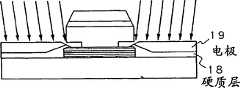
然后硬质层18作为底层在其上沉积电极层19,如图15C所示。检测部分10优点在于其两端具有底层和电极从而使检测电流仅流过自由磁层12而不通过检测部分10和磁场矫正部分20于是获得大的电阻变化。The
如果检测电流通过检测部分10和磁场矫正部分20,因为磁场矫正部分20离磁盘远,GMR元件总的电阻变化就会减小。因此在外加磁场Hsig作用下,磁场矫正部分20中磁场强度变化进而引起的电阻变化相对较小。因此,此处硬质层18和电极19仅置于沿检测部分10宽度方向的两端。然而,更简单从而耗费较少的是在检测部分10和磁场矫正部分20宽度方向的两端都沉积硬质层18和电极19。因而这是在制造费用和追求好的GMR磁头特点的折衷选择。If the detection current passes through the detecting portion 10 and the magnetic field correcting portion 20, since the magnetic field correcting portion 20 is far from the magnetic disk, the total resistance change of the GMR element is reduced. Therefore, under the action of the external magnetic field Hsig, the change of the magnetic field intensity in the magnetic field correction part 20 and thus the resistance change caused by it is relatively small. Therefore, here, the
下一步,如图15D所示,去掉双层抗蚀剂17。Next, as shown in Fig. 15D, the double resist 17 is removed.
然后,如图15E所示形成具有与检测部分10和磁场矫正部分20(图5所示)之间间隙g相关的凹槽的双层抗蚀剂17g。再通过离子铣削方法,形成对应于间隙g的凹槽,再去掉双层抗蚀剂。Then, as shown in FIG. 15E, a double-layer resist 17g having grooves corresponding to the gap g between the detection portion 10 and the magnetic field correction portion 20 (shown in FIG. 5) is formed. Then, the ion milling method is used to form a groove corresponding to the gap g, and then the double-layer resist is removed.
必须明白,尽管通过上述过程制造的图5所示的GMR元件已经说明,也可以用另一种替换方法如技术领域熟知的选择性蚀刻、分离工艺、离子铣削和光刻等工艺进行制造。It must be understood that although the GMR element shown in FIG. 5 fabricated by the above process has been described, it can also be fabricated by alternative methods such as selective etching, separation processes, ion milling and photolithography, etc., which are well known in the art.
制造第二例(图9)中反单旋转阀结构的方法与制造图5所示GMR元件的方法相同,只不过前者以反顺序形成各层。The method of fabricating the inverted single rotary valve structure in the second example (FIG. 9) is the same as that of the GMR element shown in FIG. 5, except that the layers are formed in reverse order.
制造具有双旋转阀结构的第三种GMR元件的方法同第二例中所述GMR元件相同,只不过前者额外形成了第二中间层13-2、第二被锁定磁层14-2和第二反铁磁层15-2。The method of manufacturing the third GMR element with double rotary valve structure is the same as the GMR element described in the second example, except that the former additionally forms the second intermediate layer 13-2, the second locked magnetic layer 14-2 and the second magnetic layer 14-2. Two antiferromagnetic layers 15-2.
制造第四种GMR元件的方法与第一例中的GMR元件相同,只不过如图10所示形成的层是大量的。The method of manufacturing the fourth GMR element is the same as that of the GMR element in the first example, except that a large number of layers are formed as shown in FIG. 10 .
[磁盘驱动器][Disk drive]
图16是实施本发明的磁盘驱动器的透视图。该磁盘驱动器包含按照本发明制造的GMR磁头。该磁盘驱动器包括磁盘30和放置在磁盘30上的GMR磁头32,GMR磁头32在磁盘读写操作时浮动在磁盘30上面20nm处。由普通传动器和电磁微传动器组成的两级传动器34调节GMR磁头的位置。使用无粘着滑块36防止滑块和磁盘粘着。Figure 16 is a perspective view of a disk drive embodying the present invention. The disc drive includes a GMR head fabricated in accordance with the present invention. The magnetic disk drive includes a
概要的说,本发明提供了一种新颖的GMR磁头,其中通过抑制由于被锁定磁层对自由磁层的作用产生的静磁场为自由磁层设置充分的偏置点。In summary, the present invention provides a novel GMR head in which a sufficient bias point is set for the free magnetic layer by suppressing the static magnetic field generated due to the action of the pinned magnetic layer on the free magnetic layer.
本发明进一步提供了制造上述新颖GMR磁头的方法。The present invention further provides a method of manufacturing the novel GMR head described above.
最后,本发明提供了使用上述GMR磁头中任何一个的磁盘驱动器。Finally, the present invention provides a disk drive using any of the GMR heads described above.
Claims (19)
Applications Claiming Priority (3)
| Application Number | Priority Date | Filing Date | Title |
|---|---|---|---|
| JP69597/98 | 1998-03-19 | ||
| JP06959798AJP3790356B2 (en) | 1998-03-19 | 1998-03-19 | GMR head, method for manufacturing GMR head, and magnetic disk drive |
| JP69597/1998 | 1998-03-19 |
Publications (2)
| Publication Number | Publication Date |
|---|---|
| CN1229973A CN1229973A (en) | 1999-09-29 |
| CN1110795Ctrue CN1110795C (en) | 2003-06-04 |
Family
ID=13407414
Family Applications (1)
| Application Number | Title | Priority Date | Filing Date |
|---|---|---|---|
| CN98117092AExpired - Fee RelatedCN1110795C (en) | 1998-03-19 | 1998-12-11 | GMR head, method for its manufacture, and magnetic disc drive utilizing the head |
Country Status (5)
| Country | Link |
|---|---|
| US (1) | US6327121B1 (en) |
| JP (1) | JP3790356B2 (en) |
| KR (1) | KR100284227B1 (en) |
| CN (1) | CN1110795C (en) |
| DE (1) | DE19854519A1 (en) |
Families Citing this family (15)
| Publication number | Priority date | Publication date | Assignee | Title |
|---|---|---|---|---|
| JP3692832B2 (en)* | 1999-05-21 | 2005-09-07 | 富士ゼロックス株式会社 | Recording / reproducing head and recording / reproducing disk device |
| US6469877B1 (en)* | 1999-06-15 | 2002-10-22 | Read-Rite Corporation | Spin valve device with improved exchange layer defined track width and method of fabrication |
| US6807031B2 (en) | 2000-02-08 | 2004-10-19 | Seagate Technology Llc | Single domain state laminated thin film structure for use as a magnetic layer of a transducing head |
| US6437949B1 (en)* | 2000-02-08 | 2002-08-20 | Seagate Technology Llc | Single domain state laminated thin film structure |
| JP3575683B2 (en)* | 2000-10-05 | 2004-10-13 | 松下電器産業株式会社 | Multi-element type magnetoresistive element |
| JP2001351209A (en)* | 2000-06-06 | 2001-12-21 | Fujitsu Ltd | Spin valve head, method of manufacturing the same, and magnetic disk drive |
| JP3558996B2 (en)* | 2001-03-30 | 2004-08-25 | 株式会社東芝 | Magnetoresistive element, magnetic head, magnetic reproducing device and magnetic storage device |
| JP3974587B2 (en)* | 2003-04-18 | 2007-09-12 | アルプス電気株式会社 | CPP type giant magnetoresistive head |
| US7035059B2 (en)* | 2003-07-18 | 2006-04-25 | Hitachi Global Storage Technologies, Netherland B.V. | Head with self-pinned structure having pinned layer extending beyond track edges of the free layer |
| US7118814B1 (en)* | 2004-03-02 | 2006-10-10 | Storage Technology Corporation | Apparatus and method for step-stabilization of GMR-based read sensors |
| US7324310B2 (en) | 2004-04-30 | 2008-01-29 | Hitachi Global Storage Technologies Netherlands B.V. | Self-pinned dual CPP sensor exchange pinned at stripe back-end to avoid amplitude flipping |
| JP2007088415A (en)* | 2005-08-25 | 2007-04-05 | Fujitsu Ltd | Magnetoresistive element, magnetic head, magnetic storage device, and magnetic memory device |
| US20110026169A1 (en)* | 2009-07-28 | 2011-02-03 | Hardayal Singh Gill | Dual cpp gmr head using a scissor sensor |
| JP2017040628A (en)* | 2015-08-21 | 2017-02-23 | 株式会社デンソー | Magnetic sensor |
| US11415645B2 (en)* | 2019-08-23 | 2022-08-16 | Western Digital Technologies, Inc. | Magnetic sensor array with one TMR stack having two free layers |
Citations (3)
| Publication number | Priority date | Publication date | Assignee | Title |
|---|---|---|---|---|
| CN1062425A (en)* | 1990-12-11 | 1992-07-01 | 国际商业机器公司 | Magnetoresistive Sensor Based on Spin Valve Effect |
| US5287238A (en)* | 1992-11-06 | 1994-02-15 | International Business Machines Corporation | Dual spin valve magnetoresistive sensor |
| US5648885A (en)* | 1995-08-31 | 1997-07-15 | Hitachi, Ltd. | Giant magnetoresistive effect sensor, particularly having a multilayered magnetic thin film layer |
Family Cites Families (10)
| Publication number | Priority date | Publication date | Assignee | Title |
|---|---|---|---|---|
| US4001890A (en)* | 1974-08-05 | 1977-01-04 | Honeywell Information Systems, Inc. | Double chip flying head |
| JP3208906B2 (en)* | 1993-03-24 | 2001-09-17 | 松下電器産業株式会社 | Magnetoresistive magnetic head |
| US5528440A (en)* | 1994-07-26 | 1996-06-18 | International Business Machines Corporation | Spin valve magnetoresistive element with longitudinal exchange biasing of end regions abutting the free layer, and magnetic recording system using the element |
| WO1996016339A1 (en)* | 1994-11-21 | 1996-05-30 | International Business Machines Corporation | Magnetoresistive sensor |
| US5493467A (en)* | 1994-12-27 | 1996-02-20 | International Business Machines Corporation | Yoke spin valve MR read head |
| US5838521A (en)* | 1995-04-17 | 1998-11-17 | Read-Rite Corporation | Magnetoresistive transducer having laminated magnetic shields |
| JPH0922510A (en) | 1995-07-05 | 1997-01-21 | Fujitsu Ltd | Magnetoresistive effect element, manufacturing method thereof, magnetic recording device, and manufacturing method thereof |
| DE69616676T2 (en)* | 1995-07-18 | 2002-05-16 | Hewlett-Packard Co.(A Delaware Corporation), Palo Alto | Magnetoresistive recording head |
| US5768071A (en)* | 1997-06-19 | 1998-06-16 | International Business Machines Corporation | Spin valve sensor with improved magnetic stability of the pinned layer |
| JPH1196513A (en)* | 1997-09-17 | 1999-04-09 | Fujitsu Ltd | Magnetic head and magnetic storage device having the same |
- 1998
- 1998-03-19JPJP06959798Apatent/JP3790356B2/ennot_activeExpired - Fee Related
- 1998-11-13USUS09/191,940patent/US6327121B1/ennot_activeExpired - Fee Related
- 1998-11-26DEDE19854519Apatent/DE19854519A1/ennot_activeWithdrawn
- 1998-12-11CNCN98117092Apatent/CN1110795C/ennot_activeExpired - Fee Related
- 1998-12-14KRKR1019980054782Apatent/KR100284227B1/ennot_activeExpired - Fee Related
Patent Citations (3)
| Publication number | Priority date | Publication date | Assignee | Title |
|---|---|---|---|---|
| CN1062425A (en)* | 1990-12-11 | 1992-07-01 | 国际商业机器公司 | Magnetoresistive Sensor Based on Spin Valve Effect |
| US5287238A (en)* | 1992-11-06 | 1994-02-15 | International Business Machines Corporation | Dual spin valve magnetoresistive sensor |
| US5648885A (en)* | 1995-08-31 | 1997-07-15 | Hitachi, Ltd. | Giant magnetoresistive effect sensor, particularly having a multilayered magnetic thin film layer |
Also Published As
| Publication number | Publication date |
|---|---|
| US6327121B1 (en) | 2001-12-04 |
| DE19854519A1 (en) | 1999-09-23 |
| CN1229973A (en) | 1999-09-29 |
| KR19990076556A (en) | 1999-10-15 |
| JP3790356B2 (en) | 2006-06-28 |
| JPH11273029A (en) | 1999-10-08 |
| KR100284227B1 (en) | 2001-03-02 |
Similar Documents
| Publication | Publication Date | Title |
|---|---|---|
| CN100343898C (en) | Magnetic recording head and magnetic record reproducing device | |
| CN1110795C (en) | GMR head, method for its manufacture, and magnetic disc drive utilizing the head | |
| CN1221947C (en) | Magnetic resistance effect device, magnetic head, magnetic recording equipment and storage device | |
| CN1112675C (en) | Exchange coupling film, magnetoresistance effect device, magnetoresistance effective head and method for producing exchange coupling film | |
| US8477461B2 (en) | Thin film magnetic head having a pair of magnetic layers whose magnetization is controlled by shield layers | |
| US8130475B2 (en) | Method for manufacturing CPP-type thin film magnetic head provided with a pair of magnetically free layers | |
| CN1183517C (en) | Magnetoresistance effect magnetic head and magnetic memory device with this kind of magnetic head | |
| CN1503001A (en) | Magnetic sensor, method of manufacturing the same, and magnet array suitable for the manufacturing method | |
| CN1428876A (en) | Magnetoresistive element | |
| US7038881B2 (en) | Magnetic head for perpendicular recording including a main pole having a pole tip with three tapered sides | |
| CN1480923A (en) | Rotary valve head comprising a partial current shield, method for producing said head and method for current shielding | |
| CN1221042C (en) | Manufacturing method of magnetoresistance effect element and manufacturing method of magnetoresistance effect type magnetic head | |
| CN1145146C (en) | Antiparallel pinned read head and method of manufacturing the same | |
| CN100350457C (en) | Magnetoresistance effect element, magnetic head, magnetic recording and reproducing device, and magnetic memory | |
| CN1221170A (en) | Spin valve head and method of manufacturing the same and magnetic disk drive using spin valve head | |
| CN1835084A (en) | Magnetoresistive element, magnetic head, and magnetic memory apparatus | |
| CN1271600C (en) | Spin-valve magnetoresistance effect head, composite magnetic head comprising the same, and magnetoresistance recorded medium drive | |
| US20090237839A1 (en) | Cpp-type magnetoresistance effect element having three magnetic layers | |
| CN1133978C (en) | Spinning valve sensor with improved interface between nailing layer and nailed layer | |
| CN1265357C (en) | Magnetic resistance effect magnetic head and its mfg. method | |
| US20120069474A1 (en) | Magnetic head, magnetic head assembly, and magnetic recording/reproducing apparatus | |
| KR20080055636A (en) | Magnetoresistive element, magnetic head and magnetic memory | |
| CN1352791A (en) | Spin-valve magnetoresistive effect magnetic head, composite magnetic head using same, and magnetic recording medium driving device | |
| US20060209469A1 (en) | Magnetoresistance effect reproduction head | |
| CN1551111A (en) | Magneto-resistive head and magnetic recording-reproducing device |
Legal Events
| Date | Code | Title | Description |
|---|---|---|---|
| C10 | Entry into substantive examination | ||
| SE01 | Entry into force of request for substantive examination | ||
| C06 | Publication | ||
| PB01 | Publication | ||
| C14 | Grant of patent or utility model | ||
| GR01 | Patent grant | ||
| C17 | Cessation of patent right | ||
| CF01 | Termination of patent right due to non-payment of annual fee | Granted publication date:20030604 Termination date:20100111 |