CN111078612A - FPGA-based biss-c protocol decoding system - Google Patents
FPGA-based biss-c protocol decoding systemDownload PDFInfo
- Publication number
- CN111078612A CN111078612ACN201911090254.6ACN201911090254ACN111078612ACN 111078612 ACN111078612 ACN 111078612ACN 201911090254 ACN201911090254 ACN 201911090254ACN 111078612 ACN111078612 ACN 111078612A
- Authority
- CN
- China
- Prior art keywords
- data
- biss
- clock
- decoding
- fpga
- Prior art date
- Legal status (The legal status is an assumption and is not a legal conclusion. Google has not performed a legal analysis and makes no representation as to the accuracy of the status listed.)
- Pending
Links
Images
Classifications
- G—PHYSICS
- G06—COMPUTING OR CALCULATING; COUNTING
- G06F—ELECTRIC DIGITAL DATA PROCESSING
- G06F13/00—Interconnection of, or transfer of information or other signals between, memories, input/output devices or central processing units
- G06F13/38—Information transfer, e.g. on bus
- G06F13/42—Bus transfer protocol, e.g. handshake; Synchronisation
- G06F13/4282—Bus transfer protocol, e.g. handshake; Synchronisation on a serial bus, e.g. I2C bus, SPI bus
- G—PHYSICS
- G01—MEASURING; TESTING
- G01C—MEASURING DISTANCES, LEVELS OR BEARINGS; SURVEYING; NAVIGATION; GYROSCOPIC INSTRUMENTS; PHOTOGRAMMETRY OR VIDEOGRAMMETRY
- G01C25/00—Manufacturing, calibrating, cleaning, or repairing instruments or devices referred to in the other groups of this subclass
- G01C25/005—Manufacturing, calibrating, cleaning, or repairing instruments or devices referred to in the other groups of this subclass initial alignment, calibration or starting-up of inertial devices
Landscapes
- Engineering & Computer Science (AREA)
- Physics & Mathematics (AREA)
- General Physics & Mathematics (AREA)
- Theoretical Computer Science (AREA)
- General Engineering & Computer Science (AREA)
- Manufacturing & Machinery (AREA)
- Radar, Positioning & Navigation (AREA)
- Remote Sensing (AREA)
- Mobile Radio Communication Systems (AREA)
Abstract
Translated fromChinese
Description
Translated fromChinese技术领域technical field
本发明涉及惯性导航系统校准技术领域,特别是涉及一种基于FPGA的biss- c协议的译码系统。The invention relates to the technical field of inertial navigation system calibration, in particular to an FPGA-based biss-c protocol decoding system.
背景技术Background technique
高精度惯性导航系统的姿态精度是衡量其长期导航性能的关键指标。通常, 在使用高精度惯性导航之前,必须对其精度进行评估。姿态精度评估不仅给出了 高精度惯性导航系统的姿态精度指标,而且为武器平台的精度分析提供了依据。 因此,建立仿真试验系统,模拟载体运动,并将其与车辆试验相结合,对提高惯 性导航系统试验质量具有重要意义。国内外常用的精度评定设备是高精度转台。 绝对角编码器通常用于测量转台的方位角、俯仰角和滚转角。绝对角编码器采用 串行接口协议与数据接收系统进行数据交换。数据协议biss-c是ic-haus于2002 年推出的开放式数字接口协议。biss-c接口协议为传感器和执行器提供了一种双 向快速通信标准。它可以用简单的硬件实现。适用于实时数据采集。与其它接口 相比,它在开放性、高速性、组网方式、线路延时补偿等方面具有领先优势。biss- c接口协议的译码可以采用硬件译码、软件译码或混合译码来实现。与软件译码 相比,硬件译码可以提供更高的通信速度,节省外部逻辑电路的成本。The attitude accuracy of a high-precision inertial navigation system is a key indicator to measure its long-term navigation performance. In general, before high-accuracy inertial navigation can be used, its accuracy must be evaluated. The attitude accuracy evaluation not only provides the attitude accuracy index of the high-precision inertial navigation system, but also provides the basis for the accuracy analysis of the weapon platform. Therefore, establishing a simulation test system, simulating the motion of the carrier, and combining it with the vehicle test is of great significance for improving the test quality of the inertial navigation system. The commonly used precision evaluation equipment at home and abroad is a high-precision turntable. Absolute encoders are commonly used to measure the azimuth, pitch and roll angles of turntables. The absolute angle encoder uses the serial interface protocol to exchange data with the data receiving system. The data protocol biss-c is an open digital interface protocol introduced by ic-haus in 2002. The biss-c interface protocol provides a fast bidirectional communication standard for sensors and actuators. It can be implemented with simple hardware. Suitable for real-time data acquisition. Compared with other interfaces, it has leading advantages in openness, high speed, networking mode, line delay compensation and so on. The decoding of the biss-c interface protocol can be implemented by hardware decoding, software decoding or hybrid decoding. Compared with software decoding, hardware decoding can provide higher communication speed and save the cost of external logic circuits.
但是,在传统的精度评定试验中,转台的角度信息是通过转台的上位机软件 发送给用户的,时间延迟难以准确估计。这就导致了转台输出姿态参考数据与惯 性导航系统姿态测量信息之间的时间同步困难。However, in the traditional accuracy evaluation test, the angle information of the turntable is sent to the user through the software of the upper computer of the turntable, and the time delay is difficult to estimate accurately. This leads to the difficulty of time synchronization between the output attitude reference data of the turntable and the attitude measurement information of the inertial navigation system.
发明内容SUMMARY OF THE INVENTION
有鉴于此,本发明提供了一种基于FPGA的biss-c协议的译码系统,其基于 FPGA的实时、同步、高速的硬件和软件来实现biss-c数据采集系统,对提高惯 性导航系统试验质量具有重要意义,从而更加适于实用。In view of this, the present invention provides a decoding system of the biss-c protocol based on FPGA, which realizes the biss-c data acquisition system based on the real-time, synchronous, high-speed hardware and software of the FPGA, which is helpful for improving the inertial navigation system test. Quality is important and thus more suitable for practical use.
为了达到上述目的,本发明提供的基于FPGA的biss-c协议的译码系统的 技术方案如下:In order to achieve the above object, the technical scheme of the decoding system based on the biss-c protocol of FPGA provided by the invention is as follows:
本发明提供的基于FPGA的biss-c协议的译码系统包括:The decoding system of the FPGA-based biss-c protocol provided by the present invention includes:
BISS-C编码器,用于为绝对编码器提供位置请求和时钟信息;BISS-C encoder for position request and clock information for absolute encoder;
以及接收到时钟信号后,与时钟信号同步的位置采集数据,并提供给所述数 据采集模块;And after receiving the clock signal, the position synchronizing with the clock signal collects data, and provides to the described data acquisition module;
数据采集模块,用于接收转台的slo位置数据和惯性导航系统导航数据;The data acquisition module is used to receive the slo position data of the turntable and the navigation data of the inertial navigation system;
编码模块,用于根据所述数据采集模块接收到的位置数据和导航数据进行 编码,得到编码后的数据;A coding module for coding according to the position data and the navigation data received by the data acquisition module, to obtain coded data;
解码模块,用于对从所述编码模块接收到的编码后的数据进行解码得到解 码后的数据;A decoding module for decoding the encoded data received from the encoding module to obtain the decoded data;
上位机,用于显示所述解码后的数据。The upper computer is used to display the decoded data.
本发明提供的基于FPGA的biss-c协议的译码系统还可采用以下技术措施 进一步实现。The FPGA-based biss-c protocol decoding system provided by the present invention can also be further realized by adopting the following technical measures.
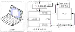
作为优选,所述数据采集模块包括FPGA最小系统电路和相应的外围电路, 其具体包括:Preferably, the data acquisition module includes an FPGA minimum system circuit and a corresponding peripheral circuit, which specifically includes:
RS422接口:用于发送ma时钟,并接收来自惯性导航系统的slo位置数据 和导航数据;RS422 interface: used to send ma clock, and receive slo position data and navigation data from inertial navigation system;
RS232接口:用于与转台和上位机通信。RS232 interface: used to communicate with the turntable and the host computer.
作为优选,基于FPGA的biss-c协议的译码系统还包括:Preferably, the decoding system based on the biss-c protocol of the FPGA also includes:
光耦合器,用于隔离实现数据采集系统的数据交互,其中,所述光耦合器 设置于接口芯片和FPGA核心模块之间。The optocoupler is used to isolate and realize the data interaction of the data acquisition system, wherein the optocoupler is arranged between the interface chip and the FPGA core module.
作为优选,所述FPGA的每一个电压都配有相应的贴片电容器。Preferably, each voltage of the FPGA is provided with a corresponding chip capacitor.
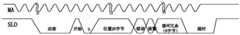
作为优选,所述时钟的工作方式包括:Preferably, the working mode of the clock includes:
时钟不工作时,时钟信号和位置信号都设置为高电平;When the clock is not working, both the clock signal and the position signal are set to high level;
当时钟开始工作时,编码器将信号设置为低,以指示第二上升沿上的“确认”;When the clock starts working, the encoder sets the signal low to indicate an "acknowledgment" on the second rising edge;
在等待n1时钟后,将有一个相邻的高电平“开始”和一个低电平“0”用作符 号;After waiting for the n1 clock, there will be an adjacent high level "start" and a low level "0" as symbols;
随后的29位是位置信息,随后是“错误”和“警告”来检查解码是否正常,“错 误”和“警告”是零,表示解码中有错误;The next 29 bits are position information, followed by "error" and "warning" to check whether the decoding is normal, "error" and "warning" are zero, indicating that there is an error in decoding;
之后,使用六位“循环冗余”校验位;当“超时”时,时钟设置为高,编码器 信号设置为低;After that, the six-bit "Cyclic Redundancy" check bit is used; when "timeout", the clock is set to high and the encoder signal is set to low;
在等待n2时钟后,编码器信号再次将其设置为高,并等待下一组数据被释 放;After waiting for n2 clocks, the encoder signal sets it high again and waits for the next set of data to be released;
其中,关于n1和n2的时钟数量不是固定的,通常是2-5个时钟。Among them, the number of clocks about n1 and n2 is not fixed, usually 2-5 clocks.
作为优选,As a preference,
所述循环冗余校验公式g(x)=x6+x+1。The cyclic redundancy check formula g(x)=x6+x+1.
作为优选,每次采集需要150个时钟周期,如果n1或n2有50个以上的时 钟,则时钟将被直接中断,采集错误,等待下一次数据采集。Preferably, each acquisition requires 150 clock cycles. If there are more than 50 clocks in n1 or n2, the clocks will be interrupted directly, and the acquisition will be wrong, waiting for the next data acquisition.
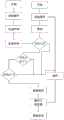
作为优选,所述解码模块的工作方式包括:Preferably, the working mode of the decoding module includes:
在初始通电或复位后,解码模块首先检测编码器发送的数据是否处于高电 平;After initial power-on or reset, the decoding module first detects whether the data sent by the encoder is at a high level;
当检测到空闲状态时,发送时钟ma。此时,根据BISS-C帧依次出现“确认”、 “开始”和“0”状态,如果检测不到,则直接进入“超时”状态,等待下次接收数据;When an idle state is detected, the clock ma is sent. At this time, according to the BISS-C frame, the "confirm", "start" and "0" states appear in sequence. If it is not detected, it will directly enter the "timeout" state and wait for the next data reception;
如果检测通过,则在“0”位后接收29位位置信号、2位检测信号和6位校验 码;If the detection is passed, then receive 29-bit position signal, 2-bit detection signal and 6-bit check code after "0" bit;
接收后,主设备停止发送时钟,等待超时结束,然后进入下一个周期;After receiving, the master device stops sending the clock, waits for the timeout to end, and then enters the next cycle;
循环冗余模块负责验证数据是否正确,其中,解码模块将接收到的29位位 置信号和2位检测信号中的31位发送到循环冗余模块。The cyclic redundancy module is responsible for verifying whether the data is correct, wherein the decoding module sends the received 29-bit position signal and 31 bits of the 2-bit detection signal to the cyclic redundancy module.
作为优选,所述循环冗余模块的校验方法包括以下步骤:Preferably, the verification method of the cyclic redundancy module comprises the following steps:
准备一帧需要校验的数据,29位位置数据+2位状态位+6位循环冗余校验 码;Prepare a frame of data to be checked, 29 bits of position data + 2 bits of status bits + 6 bits of cyclic redundancy check code;
用“000000”替换所述循环冗余校验码的最后6位,得到替换后的校验码;Replace the last 6 bits of the cyclic redundancy check code with "000000" to obtain the replaced check code;
所述替换后的校验码除以生成多项式“1000011”;The replaced check code is divided by the generator polynomial "1000011";
得到37位数据;Get 37-bit data;
除以得到余数;Divide by to get the remainder;
然后反向得到循环冗余校验码。Then reverse the cyclic redundancy check code.
应用本发明提供的基于FPGA的biss-c协议的译码系统是,利用FPGA设 计了数据采集系统。在biss-c协议中,数据采集系统能正确地向编码器提供位置 采集请求和时钟信息ma,从编码器中采集位置数据slo。分频后利用rs232传输 位置数据,并在上位机上正确显示角度位置信息。主从系统之间的最大数据交互 周期为40μs,最大ma时钟频率为10mhz,最大数据延迟为42.5ns。实验证明, 系统运行良好,角度数据显示正确,因此,其对提高惯性导航系统试验质量具有 重要意义。Using the FPGA-based biss-c protocol decoding system provided by the present invention, a data acquisition system is designed by using the FPGA. In the biss-c protocol, the data acquisition system can correctly provide the encoder with the position acquisition request and clock information ma, and collect the position data slo from the encoder. After frequency division, use rs232 to transmit position data, and display the angular position information correctly on the host computer. The maximum data exchange period between the master and slave systems is 40μs, the maximum ma clock frequency is 10mhz, and the maximum data delay is 42.5ns. Experiments show that the system works well and the angle data is displayed correctly. Therefore, it is of great significance to improve the test quality of the inertial navigation system.
附图说明Description of drawings
通过阅读下文优选实施方式的详细描述,各种其他的优点和益处对于本领 域普通技术人员将变得清楚明了。附图仅用于示出优选实施方式的目的,而并不 认为是对本发明的限制。而且在整个附图中,用相同的参考符号表示相同的部件。Various other advantages and benefits will become apparent to those of ordinary skill in the art upon reading the following detailed description of the preferred embodiments. The drawings are for the purpose of illustrating preferred embodiments only and are not to be considered limiting of the invention. Also, the same components are denoted by the same reference numerals throughout the drawings.
在附图中:In the attached image:
图1为本发明实施例方案涉及的基于FPGA的biss-c协议的译码系统的拓 扑图;Fig. 1 is the topology diagram of the decoding system based on the biss-c agreement of the FPGA that the embodiment scheme of the present invention relates to;
图2为本发明实施例方案涉及的基于FPGA的biss-c协议的译码系统的食 物连接电气结构示意图;Fig. 2 is the food connection electrical structure schematic diagram of the decoding system of the FPGA-based biss-c protocol involved in the embodiment of the present invention;
图3为本发明实施例方案涉及的基于FPGA的biss-c协议的译码系统中应 用的时钟的工作方式结构示意图;Fig. 3 is the working mode structural representation of the clock applied in the decoding system of the FPGA-based biss-c protocol that the embodiment scheme of the present invention relates to;
图4为本发明实施例方案涉及的基于FPGA的biss-c协议的译码系统中应 用的循环冗余模块的校验方法的步骤流程图。Fig. 4 is the flow chart of the steps of the verification method of the cyclic redundancy module applied in the FPGA-based biss-c protocol decoding system according to the embodiment of the present invention.
具体实施方式Detailed ways
数据协议biss-c是ic-haus于2002年推出的开放式数字接口协议。biss-c接 口协议为传感器和执行器提供了一种双向快速通信标准。它可以用简单的硬件 实现。适用于实时数据采集。与其它接口相比,它在开放性、高速性、组网方式、 线路延时补偿等方面具有领先优势。biss-c接口协议的译码可以采用硬件译码、 软件译码或混合译码来实现。与软件译码相比,硬件译码可以提供更高的通信速 度,节省外部逻辑电路的成本。The data protocol biss-c is an open digital interface protocol introduced by ic-haus in 2002. The biss-c interface protocol provides a fast bidirectional communication standard for sensors and actuators. It can be implemented with simple hardware. Suitable for real-time data acquisition. Compared with other interfaces, it has leading advantages in openness, high speed, networking mode, line delay compensation and so on. The decoding of the biss-c interface protocol can be implemented by hardware decoding, software decoding or hybrid decoding. Compared with software decoding, hardware decoding can provide higher communication speed and save the cost of external logic circuits.
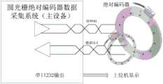
biss-c接口协议是一种开放式全双工同步串行通信协议,由点对点组网和总 线方式组成。在点对点模式下,主接口仅与从接口连接。主接口通过rs422等差 分信号将时钟提供给从接口;从接口使用slo信号线,将传感器数据从从从接口 同步传输回主接口。因此,在点对点模式下,主接口可以从从接口接收数据,并 在两个方向上与从接口通信。The biss-c interface protocol is an open full-duplex synchronous serial communication protocol consisting of point-to-point networking and bus mode. In point-to-point mode, the master interface is only connected to the slave interface. The master interface provides the clock to the slave interface through differential signals such as rs422; the slave interface uses the slo signal line to synchronously transmit sensor data from the slave interface to the master interface. Therefore, in point-to-point mode, the master interface can receive data from the slave interface and communicate with the slave interface in both directions.
基于此,本发明为解决现有技术存在的问题,提供一种一种基于FPGA的 biss-c协议的译码系统,其基于FPGA的实时、同步、高速的硬件和软件来实现 biss-c数据采集系统,对提高惯性导航系统试验质量具有重要意义。Based on this, in order to solve the problems existing in the prior art, the present invention provides a decoding system for the biss-c protocol based on FPGA, which realizes the biss-c data based on the real-time, synchronous, high-speed hardware and software of the FPGA. The acquisition system is of great significance to improving the test quality of the inertial navigation system.
为更进一步阐述本发明为达成预定发明目的所采取的技术手段及功效,以下 结合附图及较佳实施例,对依据本发明提出的基于FPGA的biss-c协议的译码 系统,其具体实施方式、结构、特征及其功效,详细说明如后。在下述说明中, 不同的“一实施例”或“实施例”指的不一定是同一实施例。此外,一或多个实施例 中的特征、结构、或特点可由任何合适形式组合。In order to further illustrate the technical means and effects adopted by the present invention to achieve the predetermined purpose of the invention, the specific implementation of the decoding system based on the FPGA-based biss-c protocol proposed by the present invention is described below in conjunction with the accompanying drawings and preferred embodiments. The method, structure, characteristics and efficacy thereof are described in detail as follows. In the following description, different "an embodiment" or "embodiments" do not necessarily refer to the same embodiment. Furthermore, the features, structures, or characteristics of one or more embodiments may be combined in any suitable form.
本文中术语“和/或”,仅仅是一种描述关联对象的关联关系,表示可以存在 三种关系,例如,A和/或B,具体的理解为:可以同时包含有A与B,可以单 独存在A,也可以单独存在B,能够具备上述三种任一种情况。The term "and/or" in this document is only an association relationship to describe the associated objects, indicating that there can be three kinds of relationships, for example, A and/or B, which is specifically understood as: A and B may be included at the same time, and a separate relationship may exist. If A exists, B may exist alone, and any of the above three situations can be provided.
本发明提供的基于FPGA的biss-c协议的译码系统包括:The decoding system of the FPGA-based biss-c protocol provided by the present invention includes:
BISS-C编码器,用于为绝对编码器提供位置请求和时钟信息;以及接收到 时钟信号后,与时钟信号同步的位置采集数据,并提供给数据采集模块;BISS-C encoder is used to provide position request and clock information for the absolute encoder; and after receiving the clock signal, the position acquisition data synchronized with the clock signal is provided to the data acquisition module;
数据采集模块,用于接收转台的slo位置数据和惯性系统的导航数据;The data acquisition module is used to receive the slo position data of the turntable and the navigation data of the inertial system;
编码模块,用于根据数据采集模块接收到的位置数据和导航数据进行编码, 得到编码后的数据;an encoding module for encoding according to the position data and navigation data received by the data acquisition module to obtain encoded data;
解码模块,用于对从编码模块接收到的编码后的数据进行解码得到解码后 的数据;a decoding module for decoding the encoded data received from the encoding module to obtain the decoded data;
上位机,用于显示所述解码后的数据。The upper computer is used to display the decoded data.
应用本发明提供的基于FPGA的biss-c协议的译码系统是,利用FPGA设 计了数据采集系统。在biss-c协议中,数据采集系统能正确地向编码器提供位置 采集请求和时钟信息ma,从编码器中采集位置数据slo。分频后利用rs232传输 位置数据,并在上位机上正确显示角度位置信息。主从系统之间的最大数据交互 周期为40μs,最大ma时钟频率为10mhz,最大数据延迟为42.5ns。实验证明, 系统运行良好,角度数据显示正确,因此,其对提高惯性导航系统试验质量具有 重要意义。Using the FPGA-based biss-c protocol decoding system provided by the present invention, a data acquisition system is designed by using the FPGA. In the biss-c protocol, the data acquisition system can correctly provide the encoder with the position acquisition request and clock information ma, and collect the position data slo from the encoder. After frequency division, use rs232 to transmit position data, and display the angular position information correctly on the host computer. The maximum data exchange period between the master and slave systems is 40μs, the maximum ma clock frequency is 10mhz, and the maximum data delay is 42.5ns. Experiments show that the system works well and the angle data is displayed correctly. Therefore, it is of great significance to improve the test quality of the inertial navigation system.
其中,数据采集模块包括FPGA最小系统电路和相应的外围电路,其具体 包括:Among them, the data acquisition module includes the FPGA minimum system circuit and the corresponding peripheral circuits, which specifically include:
RS422接口:用于发送ma时钟,并接收来自惯性导航系统的slo位置数据 和导航数据;RS422 interface: used to send ma clock, and receive slo position data and navigation data from inertial navigation system;
RS232接口:用于与转台和上位机通信。RS232 interface: used to communicate with the turntable and the host computer.
其中,基于FPGA的biss-c协议的译码系统还包括:Among them, the FPGA-based biss-c protocol decoding system also includes:
光耦合器,用于隔离实现数据采集系统的数据交互,其中,光耦合器设置 于接口芯片和FPGA核心模块之间。The optocoupler is used to isolate and realize the data interaction of the data acquisition system, wherein the optocoupler is arranged between the interface chip and the FPGA core module.
其中,FPGA的每一个电压都配有相应的贴片电容器。Among them, each voltage of the FPGA is equipped with a corresponding chip capacitor.
其中,时钟的工作方式包括:Among them, the working methods of the clock include:
时钟不工作时,时钟信号和位置信号都设置为高电平;When the clock is not working, both the clock signal and the position signal are set to high level;
当时钟开始工作时,编码器将信号设置为低,以指示第二上升沿上的“确认”;When the clock starts working, the encoder sets the signal low to indicate an "acknowledgment" on the second rising edge;
在等待n1时钟后,将有一个相邻的高电平“开始”和一个低电平“0”用作符 号;After waiting for the n1 clock, there will be an adjacent high level "start" and a low level "0" as symbols;
随后的29位是位置信息,随后是“错误”和“警告”来检查解码是否正常,“错 误”和“警告”是零,表示解码中有错误;The next 29 bits are position information, followed by "error" and "warning" to check whether the decoding is normal, "error" and "warning" are zero, indicating that there is an error in decoding;
之后,使用六位“循环冗余”校验位;当“超时”时,时钟设置为高,编码器 信号设置为低;After that, the six-bit "Cyclic Redundancy" check bit is used; when "timeout", the clock is set to high and the encoder signal is set to low;
在等待n2时钟后,编码器信号再次将其设置为高,并等待下一组数据被释 放;After waiting for n2 clocks, the encoder signal sets it high again and waits for the next set of data to be released;
其中,关于n1和n2的时钟数量不是固定的,通常是2-5个时钟。Among them, the number of clocks about n1 and n2 is not fixed, usually 2-5 clocks.
其中,in,
循环冗余校验公式g(x)=x6+x+1。Cyclic redundancy check formula g(x)=x6+x+1.
其中,每次采集需要150个时钟周期,如果n1或n2有50个以上的时钟, 则时钟将被直接中断,采集错误,等待下一次数据采集。Among them, 150 clock cycles are required for each acquisition. If there are more than 50 clocks in n1 or n2, the clocks will be interrupted directly, and the acquisition will be wrong, waiting for the next data acquisition.
其中,解码模块的工作方式包括:Among them, the working methods of the decoding module include:
在初始通电或复位后,解码模块首先检测编码器发送的数据是否处于高电 平;After initial power-on or reset, the decoding module first detects whether the data sent by the encoder is at a high level;
当检测到空闲状态时,发送时钟ma。此时,根据BISS-C帧依次出现“确认”、 “开始”和“0”状态,如果检测不到,则直接进入“超时”状态,等待下次接收数据;When an idle state is detected, the clock ma is sent. At this time, according to the BISS-C frame, the "confirm", "start" and "0" states appear in sequence. If it is not detected, it will directly enter the "timeout" state and wait for the next data reception;
如果检测通过,则在“0”位后接收29位位置信号、2位检测信号和6位校验 码;If the detection is passed, then receive 29-bit position signal, 2-bit detection signal and 6-bit check code after "0" bit;
接收后,主设备停止发送时钟,等待超时结束,然后进入下一个周期;After receiving, the master device stops sending the clock, waits for the timeout to end, and then enters the next cycle;
循环冗余模块负责验证数据是否正确,其中,解码模块将接收到的29位位 置信号和2位检测信号中的31位发送到循环冗余模块。The cyclic redundancy module is responsible for verifying whether the data is correct, wherein the decoding module sends the received 29-bit position signal and 31 bits of the 2-bit detection signal to the cyclic redundancy module.
其中,循环冗余模块的校验方法包括以下步骤:Wherein, the verification method of the cyclic redundancy module includes the following steps:
准备一帧需要校验的数据,29位位置数据+2位状态位+6位循环冗余校验 码;Prepare a frame of data to be checked, 29 bits of position data + 2 bits of status bits + 6 bits of cyclic redundancy check code;
用“000000”替换循环冗余校验码的最后6位,得到替换后的校验码;Replace the last 6 bits of the cyclic redundancy check code with "000000" to obtain the replaced check code;
替换后的校验码除以生成多项式“1000011”;The replaced check code is divided by the generator polynomial "1000011";
得到37位数据;Get 37-bit data;
除以得到余数;Divide by to get the remainder;
然后反向得到循环冗余校验码。Then reverse the cyclic redundancy check code.
实验验证过程如下:The experimental verification process is as follows:
实验中,时钟信号ma采用1.25mhz,编码器在这些有效时钟的上升沿应答 位置数据。上信道1是时钟信号ma,下信道2是slo数据信号。可以看出,slo 数据信号符合biss-c协议以及时钟信号。数据段有39个有效数据,所示数据为“1 0 101110110010000011101 1 1100101”。根据biss协议,错误位“1”表示所传输的 位置信息已通过内置的安全检查算法进行了检查;警告位“1”表示光栅尺和读取 窗口干净,表示此时编码器工作良好。从上面可以看出,crc为“000111”,计算 出的crc校验位相同,说明所采集的数据是有效的、正确的。主机也可以正确地 读取数据。按以下步骤计算:1)绝对编码器的脉冲数减去转台上的固定机械零 位;2)除以2^29-1再乘以360°。这说明整个基于FPGA的biss-c协议接口电路 达到了通信和解码的目的。In the experiment, the clock signal ma is 1.25mhz, and the encoder responds to the position data on the rising edge of these valid clocks. The upper channel 1 is the clock signal ma, and the lower channel 2 is the slo data signal. It can be seen that the slo data signal conforms to the biss-c protocol and the clock signal. The data segment has 39 valid data, and the data shown is "1 0 101110110010000011101 1 1100101". According to the biss protocol, the error bit "1" indicates that the transmitted position information has been checked by the built-in security check algorithm; the warning bit "1" indicates that the grating scale and reading window are clean, indicating that the encoder works well at this time. As can be seen from the above, crc is "000111", and the calculated crc check digit is the same, indicating that the collected data is valid and correct. The host can also read the data correctly. Calculate according to the following steps: 1) The pulse number of the absolute encoder minus the fixed mechanical zero position on the turntable; 2) Divide by 2^29-1 and multiply by 360°. This shows that the entire FPGA-based biss-c protocol interface circuit achieves the purpose of communication and decoding.
本实施例利用FPGA设计了数据采集系统。在biss-c协议中,数据采集系统 能正确地向编码器提供位置采集请求和时钟信息ma,从编码器中采集位置数据 slo。分频后利用rs232传输位置数据,并在上位机上正确显示角度位置信息。主 从系统之间的最大数据交互周期为40μs,最大ma时钟频率为10mhz,最大数 据延迟为42.5ns。实验证明,系统运行良好,角度数据显示正确。This embodiment uses FPGA to design a data acquisition system. In the biss-c protocol, the data acquisition system can correctly provide the encoder with the position acquisition request and clock information ma, and collect the position data slo from the encoder. After frequency division, use rs232 to transmit position data, and display the angular position information correctly on the host computer. The maximum data exchange period between the master and slave systems is 40μs, the maximum ma clock frequency is 10mhz, and the maximum data delay is 42.5ns. Experiments show that the system works well and the angle data is displayed correctly.
尽管已描述了本发明的优选实施例,但本领域内的技术人员一旦得知了基 本创造性概念,则可对这些实施例作出另外的变更和修改。所以,所附权利要求 意欲解释为包括优选实施例以及落入本发明范围的所有变更和修改。Although preferred embodiments of the present invention have been described, additional changes and modifications to these embodiments may occur to those skilled in the art once the basic inventive concepts are known. Therefore, the appended claims are intended to be construed to include the preferred embodiment and all changes and modifications that fall within the scope of the present invention.
显然,本领域的技术人员可以对本发明进行各种改动和变型而不脱离本发 明的精神和范围。这样,倘若本发明的这些修改和变型属于本发明权利要求及其 等同技术的范围之内,则本发明也意图包含这些改动和变型在内。It will be apparent to those skilled in the art that various modifications and variations can be made in the present invention without departing from the spirit and scope of the invention. Thus, provided that these modifications and variations of the present invention fall within the scope of the claims of the present invention and their equivalents, the present invention is also intended to include these modifications and variations.
Claims (9)
Translated fromChinesePriority Applications (1)
| Application Number | Priority Date | Filing Date | Title |
|---|---|---|---|
| CN201911090254.6ACN111078612A (en) | 2019-11-08 | 2019-11-08 | FPGA-based biss-c protocol decoding system |
Applications Claiming Priority (1)
| Application Number | Priority Date | Filing Date | Title |
|---|---|---|---|
| CN201911090254.6ACN111078612A (en) | 2019-11-08 | 2019-11-08 | FPGA-based biss-c protocol decoding system |
Publications (1)
| Publication Number | Publication Date |
|---|---|
| CN111078612Atrue CN111078612A (en) | 2020-04-28 |
Family
ID=70310748
Family Applications (1)
| Application Number | Title | Priority Date | Filing Date |
|---|---|---|---|
| CN201911090254.6APendingCN111078612A (en) | 2019-11-08 | 2019-11-08 | FPGA-based biss-c protocol decoding system |
Country Status (1)
| Country | Link |
|---|---|
| CN (1) | CN111078612A (en) |
Cited By (7)
| Publication number | Priority date | Publication date | Assignee | Title |
|---|---|---|---|---|
| CN111505934A (en)* | 2020-04-30 | 2020-08-07 | 成都卡诺普自动化控制技术有限公司 | Method for improving acquisition speed and accuracy of servo driver based on BISS encoder |
| CN112729311A (en)* | 2020-12-25 | 2021-04-30 | 湖南航天机电设备与特种材料研究所 | Sampling method and sampling system of inertial navigation system |
| CN113535614A (en)* | 2021-09-13 | 2021-10-22 | 之江实验室 | Communication system for decoding BISS-C protocol |
| CN114020660A (en)* | 2021-12-20 | 2022-02-08 | 河北威赛特科技有限公司 | Decoding method, device and terminal device based on BISS-C protocol |
| CN115017095A (en)* | 2022-08-05 | 2022-09-06 | 微传智能科技(常州)有限公司 | Current output type AK protocol wheel speed chip communication system and method |
| CN115145857A (en)* | 2022-09-05 | 2022-10-04 | 中国船舶重工集团公司第七0七研究所 | Interface protocol converter conversion method and FPGA system for executing method |
| CN115866076A (en)* | 2022-11-04 | 2023-03-28 | 北京航天自动控制研究所 | A FPGA-based asynchronous BiSS-C protocol decoding method |
Citations (5)
| Publication number | Priority date | Publication date | Assignee | Title |
|---|---|---|---|---|
| CN102111161A (en)* | 2010-11-16 | 2011-06-29 | 北京航天数控系统有限公司 | Method and device for acquiring encoder data |
| CN105119907A (en)* | 2015-07-22 | 2015-12-02 | 哈尔滨工业大学 | FPGA-based BiSS-C communication protocol method |
| CN105389286A (en)* | 2015-10-29 | 2016-03-09 | 中国科学院长春光学精密机械与物理研究所 | BISS C protocol data acquisition and display apparatus |
| CN208433973U (en)* | 2018-07-20 | 2019-01-25 | 中国航空工业集团公司北京航空精密机械研究所 | The acquisition of single reading head data and how main reception device based on BiSS C agreement |
| CN109359068A (en)* | 2018-10-31 | 2019-02-19 | 天津理工大学 | Labview-based method for processing angle measurement data of circular grating with high throughput |
- 2019
- 2019-11-08CNCN201911090254.6Apatent/CN111078612A/enactivePending
Patent Citations (5)
| Publication number | Priority date | Publication date | Assignee | Title |
|---|---|---|---|---|
| CN102111161A (en)* | 2010-11-16 | 2011-06-29 | 北京航天数控系统有限公司 | Method and device for acquiring encoder data |
| CN105119907A (en)* | 2015-07-22 | 2015-12-02 | 哈尔滨工业大学 | FPGA-based BiSS-C communication protocol method |
| CN105389286A (en)* | 2015-10-29 | 2016-03-09 | 中国科学院长春光学精密机械与物理研究所 | BISS C protocol data acquisition and display apparatus |
| CN208433973U (en)* | 2018-07-20 | 2019-01-25 | 中国航空工业集团公司北京航空精密机械研究所 | The acquisition of single reading head data and how main reception device based on BiSS C agreement |
| CN109359068A (en)* | 2018-10-31 | 2019-02-19 | 天津理工大学 | Labview-based method for processing angle measurement data of circular grating with high throughput |
Cited By (7)
| Publication number | Priority date | Publication date | Assignee | Title |
|---|---|---|---|---|
| CN111505934A (en)* | 2020-04-30 | 2020-08-07 | 成都卡诺普自动化控制技术有限公司 | Method for improving acquisition speed and accuracy of servo driver based on BISS encoder |
| CN112729311A (en)* | 2020-12-25 | 2021-04-30 | 湖南航天机电设备与特种材料研究所 | Sampling method and sampling system of inertial navigation system |
| CN113535614A (en)* | 2021-09-13 | 2021-10-22 | 之江实验室 | Communication system for decoding BISS-C protocol |
| CN114020660A (en)* | 2021-12-20 | 2022-02-08 | 河北威赛特科技有限公司 | Decoding method, device and terminal device based on BISS-C protocol |
| CN115017095A (en)* | 2022-08-05 | 2022-09-06 | 微传智能科技(常州)有限公司 | Current output type AK protocol wheel speed chip communication system and method |
| CN115145857A (en)* | 2022-09-05 | 2022-10-04 | 中国船舶重工集团公司第七0七研究所 | Interface protocol converter conversion method and FPGA system for executing method |
| CN115866076A (en)* | 2022-11-04 | 2023-03-28 | 北京航天自动控制研究所 | A FPGA-based asynchronous BiSS-C protocol decoding method |
Similar Documents
| Publication | Publication Date | Title |
|---|---|---|
| CN111078612A (en) | FPGA-based biss-c protocol decoding system | |
| CN105389286A (en) | BISS C protocol data acquisition and display apparatus | |
| CN102831096B (en) | A kind of 1553B bus protocol IP kernel | |
| WO2018196498A1 (en) | Biss protocol data decoding method and interface system | |
| CN108318028B (en) | Design method of navigation system core processing circuit | |
| CN104008078B (en) | Method for high-speed transmission between data transmission boards based on FPGA | |
| CN101777034B (en) | RS422 asynchronous serial card with hardware timed sending function and communication method thereof | |
| CN111949593B (en) | Clock signal monitor for slave devices on a master-slave bus | |
| CN105119907A (en) | FPGA-based BiSS-C communication protocol method | |
| CN104954096A (en) | One-master multi-slave high-speed synchronous serial communication data transmission method | |
| CN102262572A (en) | Inter integrated circuit (IIC) bus interface controller with cyclic redundancy checking (CRC) function | |
| CN101210821A (en) | Coarse-fine coupling method in dual-channel shaft angle conversion and measurement | |
| CN208433973U (en) | The acquisition of single reading head data and how main reception device based on BiSS C agreement | |
| CN104361299A (en) | Security system, multilevel security controlling system and location information reading method thereof | |
| CN114518782B (en) | Micro control unit, motor rotation speed measuring method and system and storage medium | |
| CN114460882A (en) | Incremental encoder pulse detection circuit based on programmable logic array | |
| WO1991009362A1 (en) | Pulse count type communication system | |
| CN108647175A (en) | A kind of multi-protocol data acquisition Small-sized C PCI board card | |
| WO2022000813A1 (en) | Signal conversion method, chip, and household appliance | |
| Ye et al. | Decoding of BISS-C Protocol Based on FPGA | |
| CN201293793Y (en) | Digital wind measurement sensor | |
| CN206989881U (en) | A kind of high-speed, high precision angular displacement measuring circuit plate | |
| KR101271660B1 (en) | Error detection method of image data for camera test system by using error correction and crc codes | |
| RU2510585C2 (en) | Method for communication of self-contained topographic precise positioning and navigation equipment with onboard computer | |
| CN101592468B (en) | Ring addressing method and system for pseudo-random code displacement sensor |
Legal Events
| Date | Code | Title | Description |
|---|---|---|---|
| PB01 | Publication | ||
| PB01 | Publication | ||
| SE01 | Entry into force of request for substantive examination | ||
| SE01 | Entry into force of request for substantive examination | ||
| RJ01 | Rejection of invention patent application after publication | Application publication date:20200428 | |
| RJ01 | Rejection of invention patent application after publication |