CN111067667B - Force measuring device and pushing assembly thereof - Google Patents
Force measuring device and pushing assembly thereofDownload PDFInfo
- Publication number
- CN111067667B CN111067667BCN201911379148.XACN201911379148ACN111067667BCN 111067667 BCN111067667 BCN 111067667BCN 201911379148 ACN201911379148 ACN 201911379148ACN 111067667 BCN111067667 BCN 111067667B
- Authority
- CN
- China
- Prior art keywords
- push
- distal end
- tether
- elastic tube
- spacer
- Prior art date
- Legal status (The legal status is an assumption and is not a legal conclusion. Google has not performed a legal analysis and makes no representation as to the accuracy of the status listed.)
- Active
Links
Images


Classifications
- A—HUMAN NECESSITIES
- A61—MEDICAL OR VETERINARY SCIENCE; HYGIENE
- A61F—FILTERS IMPLANTABLE INTO BLOOD VESSELS; PROSTHESES; DEVICES PROVIDING PATENCY TO, OR PREVENTING COLLAPSING OF, TUBULAR STRUCTURES OF THE BODY, e.g. STENTS; ORTHOPAEDIC, NURSING OR CONTRACEPTIVE DEVICES; FOMENTATION; TREATMENT OR PROTECTION OF EYES OR EARS; BANDAGES, DRESSINGS OR ABSORBENT PADS; FIRST-AID KITS
- A61F2/00—Filters implantable into blood vessels; Prostheses, i.e. artificial substitutes or replacements for parts of the body; Appliances for connecting them with the body; Devices providing patency to, or preventing collapsing of, tubular structures of the body, e.g. stents
- A61F2/02—Prostheses implantable into the body
- A61F2/24—Heart valves ; Vascular valves, e.g. venous valves; Heart implants, e.g. passive devices for improving the function of the native valve or the heart muscle; Transmyocardial revascularisation [TMR] devices; Valves implantable in the body
- A61F2/2442—Annuloplasty rings or inserts for correcting the valve shape; Implants for improving the function of a native heart valve
- A61F2/2463—Implants forming part of the valve leaflets
- A—HUMAN NECESSITIES
- A61—MEDICAL OR VETERINARY SCIENCE; HYGIENE
- A61B—DIAGNOSIS; SURGERY; IDENTIFICATION
- A61B90/00—Instruments, implements or accessories specially adapted for surgery or diagnosis and not covered by any of the groups A61B1/00 - A61B50/00, e.g. for luxation treatment or for protecting wound edges
- A61B90/06—Measuring instruments not otherwise provided for
- A—HUMAN NECESSITIES
- A61—MEDICAL OR VETERINARY SCIENCE; HYGIENE
- A61F—FILTERS IMPLANTABLE INTO BLOOD VESSELS; PROSTHESES; DEVICES PROVIDING PATENCY TO, OR PREVENTING COLLAPSING OF, TUBULAR STRUCTURES OF THE BODY, e.g. STENTS; ORTHOPAEDIC, NURSING OR CONTRACEPTIVE DEVICES; FOMENTATION; TREATMENT OR PROTECTION OF EYES OR EARS; BANDAGES, DRESSINGS OR ABSORBENT PADS; FIRST-AID KITS
- A61F2/00—Filters implantable into blood vessels; Prostheses, i.e. artificial substitutes or replacements for parts of the body; Appliances for connecting them with the body; Devices providing patency to, or preventing collapsing of, tubular structures of the body, e.g. stents
- A61F2/02—Prostheses implantable into the body
- A61F2/24—Heart valves ; Vascular valves, e.g. venous valves; Heart implants, e.g. passive devices for improving the function of the native valve or the heart muscle; Transmyocardial revascularisation [TMR] devices; Valves implantable in the body
- A61F2/2427—Devices for manipulating or deploying heart valves during implantation
- A61F2/2436—Deployment by retracting a sheath
- A—HUMAN NECESSITIES
- A61—MEDICAL OR VETERINARY SCIENCE; HYGIENE
- A61F—FILTERS IMPLANTABLE INTO BLOOD VESSELS; PROSTHESES; DEVICES PROVIDING PATENCY TO, OR PREVENTING COLLAPSING OF, TUBULAR STRUCTURES OF THE BODY, e.g. STENTS; ORTHOPAEDIC, NURSING OR CONTRACEPTIVE DEVICES; FOMENTATION; TREATMENT OR PROTECTION OF EYES OR EARS; BANDAGES, DRESSINGS OR ABSORBENT PADS; FIRST-AID KITS
- A61F2/00—Filters implantable into blood vessels; Prostheses, i.e. artificial substitutes or replacements for parts of the body; Appliances for connecting them with the body; Devices providing patency to, or preventing collapsing of, tubular structures of the body, e.g. stents
- A61F2/02—Prostheses implantable into the body
- A61F2/24—Heart valves ; Vascular valves, e.g. venous valves; Heart implants, e.g. passive devices for improving the function of the native valve or the heart muscle; Transmyocardial revascularisation [TMR] devices; Valves implantable in the body
- A61F2/2442—Annuloplasty rings or inserts for correcting the valve shape; Implants for improving the function of a native heart valve
- A61F2/2466—Delivery devices therefor
- A—HUMAN NECESSITIES
- A61—MEDICAL OR VETERINARY SCIENCE; HYGIENE
- A61B—DIAGNOSIS; SURGERY; IDENTIFICATION
- A61B90/00—Instruments, implements or accessories specially adapted for surgery or diagnosis and not covered by any of the groups A61B1/00 - A61B50/00, e.g. for luxation treatment or for protecting wound edges
- A61B90/06—Measuring instruments not otherwise provided for
- A61B2090/064—Measuring instruments not otherwise provided for for measuring force, pressure or mechanical tension
Landscapes
- Health & Medical Sciences (AREA)
- Cardiology (AREA)
- Life Sciences & Earth Sciences (AREA)
- Engineering & Computer Science (AREA)
- Public Health (AREA)
- Biomedical Technology (AREA)
- Heart & Thoracic Surgery (AREA)
- Veterinary Medicine (AREA)
- Oral & Maxillofacial Surgery (AREA)
- Animal Behavior & Ethology (AREA)
- General Health & Medical Sciences (AREA)
- Vascular Medicine (AREA)
- Transplantation (AREA)
- Surgery (AREA)
- Nuclear Medicine, Radiotherapy & Molecular Imaging (AREA)
- Pathology (AREA)
- Medical Informatics (AREA)
- Molecular Biology (AREA)
- Measuring Pulse, Heart Rate, Blood Pressure Or Blood Flow (AREA)
Abstract
Description
Translated fromChinese技术领域technical field
本发明涉及医疗器械领域,特别是涉及一种测力装置及其推送组件。The invention relates to the field of medical instruments, in particular to a force measuring device and a push assembly thereof.
背景技术Background technique
一些已知的假体心脏瓣膜(例如假体二尖瓣)包括一个或多个系绳,系绳从瓣膜延伸到心脏的外部,并且用心尖垫片固定到心脏的外心室壁。通过系绳的约束力,瓣膜在心脏收缩的过程中不会被挤入到心房内,从而降低血液从二尖瓣处反流至心房内的风险。Some known prosthetic heart valves (eg, prosthetic mitral valves) include one or more tethers that extend from the valve to the exterior of the heart and are secured to the outer ventricular wall of the heart with apical spacers. The restraint of the tether prevents the valve from being squeezed into the atrium during systole, thereby reducing the risk of regurgitation of blood from the mitral valve into the atrium.
系绳的张紧程度决定了心脏瓣膜的固定效果。当系绳松弛,心脏瓣膜无法被系绳拉向心尖,当心脏收缩期,心室的血流冲击瓣膜,此时心脏瓣膜会向心房侧移动,从而在原生瓣膜和植入心脏瓣膜之间产生缝隙,从而产生了瓣周漏的现象,使得手术失败。当系绳过度张紧,使得心肌过度被压缩,影响到心脏泵血,严重的话也会使得心肌受损而产生心衰。The degree of tension in the tether determines how well the heart valve is held in place. When the tether is slack, the heart valve cannot be pulled toward the apex by the tether. During systole, blood flow from the ventricle hits the valve, and the heart valve moves toward the atrium, creating a gap between the native valve and the implanted heart valve. , resulting in paravalvular leakage and failure of the operation. When the tether is too tight, the myocardium is over-compressed, affecting the pumping of the heart, and in severe cases, the myocardium is damaged and heart failure occurs.
目前,现有的装置还存在一些问题,例如心尖垫片不能较好地从装置上释放等。At present, the existing devices still have some problems, such as the apical spacer cannot be released from the device well.
发明内容SUMMARY OF THE INVENTION
基于此,针对上述问题,有必要提供一种测力装置及其推送组件。Based on this, in view of the above problems, it is necessary to provide a force measuring device and a push assembly thereof.
一种推送组件,所述推送组件用于与心尖垫片可释放地连接,所述心尖垫片用于将植入到心脏内的心脏瓣膜的系绳固定在心脏外,包括:A push assembly for releasably connecting with an apical spacer for securing a tether of a heart valve implanted in the heart outside the heart, comprising:
推送外壳;push the shell;
接合件,所述接合件设置于所述推动外壳上,且远端伸出所述推送外壳,所述接合件用于与所述心尖垫片连接,所述心尖垫片设置有用于与所述接合件连接的固定孔,所述接合件的远端插设于所述固定孔,当所述心尖垫片装载至所述接合件后,所述接合件的远端的尺寸大于所述固定孔,当所述接合件释放所述心尖垫片时,所述接合件的远端的尺寸减小至从所述固定孔中脱离。an engaging piece, the engaging piece is arranged on the pushing shell, and the distal end extends out of the pushing shell, the engaging piece is used for connecting with the apex spacer, and the apex spacer is provided for connecting with the apex spacer a fixing hole connected by an engaging piece, the distal end of the engaging piece is inserted into the fixing hole, and after the cardiac apex spacer is loaded into the engaging piece, the size of the distal end of the engaging piece is larger than that of the fixing hole , when the engagement member releases the apical spacer, the distal end of the engagement member is reduced in size to disengage from the securing hole.
在其中一个实施例中,所述接合件包括:In one embodiment, the joint includes:
弹性管,所述弹性管固定设置于所述推送外壳,所述弹性管的远端伸出所述推送外壳,且所述弹性管的延伸方向与所述推送外壳的中心轴平行,所述弹性管的远端用于与所述心尖垫片连接;an elastic tube, the elastic tube is fixedly arranged on the push housing, the distal end of the elastic tube extends out of the push housing, and the extension direction of the elastic tube is parallel to the central axis of the push housing, the elastic tube extends the distal end of the tube is used to connect with the apical spacer;
填充芯,所述填充芯可滑动设置于所述弹性管内,当所述填充芯滑动至与所述弹性管的远端齐平时,所述弹性管的远端的尺寸大于所述固定孔,当所述填充芯向近端回撤时,所述弹性管的远端的尺寸减小至从所述固定孔中脱离。A filling core, the filling core can be slidably arranged in the elastic tube, when the filling core slides to be flush with the distal end of the elastic tube, the size of the distal end of the elastic tube is larger than the fixing hole, when As the core is retracted proximally, the distal end of the elastic tube is reduced in size to disengage from the fixation hole.
在其中一个实施例中,所述弹性管的远端周壁上设置有多个缺口。In one embodiment, a plurality of notches are provided on the peripheral wall of the distal end of the elastic tube.
在其中一个实施例中,所述接合件还包括:In one of the embodiments, the joint further includes:
推送块,所述推送块滑动设置于所述推送外壳,所述填充芯固定设置于所述推送块,且所述填充芯的远端伸出所述推送块。A push block, the push block is slidably arranged on the push shell, the filling core is fixedly arranged on the push block, and the distal end of the filling core extends out of the push block.
在其中一个实施例中,所述推动外壳内设置有弹簧,所述推送块与所述弹簧连接。In one of the embodiments, a spring is provided in the push housing, and the push block is connected with the spring.
在其中一个实施例中,所述推送块的远端与所述弹簧的近端抵接。In one embodiment, the distal end of the push block abuts the proximal end of the spring.
在其中一个实施例中,所述推送外壳的侧壁设置有滑轨,所述推送块滑动设置于所述滑轨内。In one embodiment, a sliding rail is provided on the side wall of the pushing housing, and the pushing block is slidably arranged in the sliding rail.
在其中一个实施例中,所述弹性管及所述填充芯的数量均为2个。In one embodiment, the number of the elastic tubes and the filling cores are both two.
在其中一个实施例中,所述固定孔为盲孔。In one of the embodiments, the fixing holes are blind holes.
一种测力装置,包括上述任一所述的推送组件。A force measuring device, comprising any of the above-mentioned pushing components.
上述测力装置及其推送组件,当心尖垫片装载至接合件后,接合件的远端的尺寸大于固定孔,当接合件释放心尖垫片时,接合件的远端的尺寸减小至从固定孔中脱离,心尖垫片能够较牢固地固定在测力装置上,并且可以较方便地从测力装置上释放。The above-mentioned force measuring device and its pushing assembly, when the apical gasket is loaded into the joint, the size of the distal end of the joint is larger than the fixing hole, and when the joint releases the apex gasket, the size of the distal end of the joint is reduced to from If it is disengaged from the fixing hole, the cardiac apex gasket can be firmly fixed on the force measuring device, and can be released from the force measuring device more conveniently.
附图说明Description of drawings
图1为本申请一实施例的心脏瓣膜植入心脏后的结构示意图;1 is a schematic structural diagram of a heart valve after implantation into a heart according to an embodiment of the application;
图2为本申请第一实施例的测力装置的结构示意图;2 is a schematic structural diagram of the force measuring device according to the first embodiment of the application;
图3为图2所示的测力装置的推送组件的局部剖切图;Figure 3 is a partial cutaway view of the push assembly of the force measuring device shown in Figure 2;
图4为图2所示的测力装置的推送组件的剖视图;Fig. 4 is a sectional view of the push assembly of the force measuring device shown in Fig. 2;
图5为图1所示的心尖垫片的结构示意图;FIG. 5 is a schematic structural diagram of the apical spacer shown in FIG. 1;
图6为图2所示的测力装置与心尖垫片组装后的局部剖切图;FIG. 6 is a partial cutaway view of the force measuring device shown in FIG. 2 and the apical gasket after being assembled;
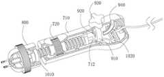
图7为图2所示的测力装置的局部剖切图;Figure 7 is a partial cutaway view of the force measuring device shown in Figure 2;
图8为图2所示的测力装置在一状态下的局部剖切图;Fig. 8 is a partial cutaway view of the force measuring device shown in Fig. 2 in a state;
图9为图2所示的测力装置在另一状态下的局部剖切图;Fig. 9 is a partial cutaway view of the force measuring device shown in Fig. 2 in another state;
图10为图2所示的测力装置的系绳锁定件与系绳连接后的结构示意图;FIG. 10 is a schematic structural diagram of the tether locking member of the force measuring device shown in FIG. 2 after being connected to the tether;
图11为图2所示的测力装置的系绳锁定件的爆炸图;Figure 11 is an exploded view of the tether lock of the force measuring device shown in Figure 2;
图12为本申请第二实施例的测力装置的结构示意图;12 is a schematic structural diagram of a force measuring device according to the second embodiment of the application;
图13为图12所示的测力装置与系绳连接后在一种状态下的局部剖切图;Fig. 13 is a partial cutaway view of the force measuring device shown in Fig. 12 in one state after being connected to the tether;
图14为图12所示的测力装置与系绳连接后在另一状态下的局部剖切图;Figure 14 is a partial cutaway view of the force measuring device shown in Figure 12 in another state after being connected to the tether;
图15为本申请第三实施例的测力装置的结构示意图;15 is a schematic structural diagram of a force measuring device according to a third embodiment of the application;
图16为图15所示的测力装置的局部剖切图;Figure 16 is a partial cutaway view of the force measuring device shown in Figure 15;
图17为图15所示的测力装置的局部剖切后的爆炸图;Figure 17 is an exploded view of the force measuring device shown in Figure 15 after a partial cut;
图18为图15所示的测力装置与系绳连接后的局部剖切图。FIG. 18 is a partial cutaway view of the force measuring device shown in FIG. 15 after being connected to the tether.
具体实施方式Detailed ways
为使本发明的上述目的、特征和优点能够更加明显易懂,下面结合附图对本发明的具体实施方式做详细的说明。在下面的描述中阐述了很多具体细节以便于充分理解本发明。但是本发明能够以很多不同于在此描述的其它方式来实施,本领域技术人员可以在不违背本发明内涵的情况下做类似改进,因此本发明不受下面公开的具体实施的限制。In order to make the above objects, features and advantages of the present invention more clearly understood, the specific embodiments of the present invention will be described in detail below with reference to the accompanying drawings. In the following description, numerous specific details are set forth in order to provide a thorough understanding of the present invention. However, the present invention can be implemented in many other ways different from those described herein, and those skilled in the art can make similar improvements without departing from the connotation of the present invention. Therefore, the present invention is not limited by the specific implementation disclosed below.
需要说明的是,当元件被称为“固定于”或“设置于”另一个元件,它可以直接在另一个元件上或者也可以存在居中的元件。当一个元件被认为是“连接”另一个元件,它可以是直接连接到另一个元件或者可能同时存在居中元件。本文所使用的术语“垂直的”、“水平的”、“左”、“右”以及类似的表述只是为了说明的目的,并不表示是唯一的实施方式。It should be noted that when an element is referred to as being "fixed to" or "disposed on" another element, it can be directly on the other element or an intervening element may also be present. When an element is referred to as being "connected" to another element, it can be directly connected to the other element or intervening elements may also be present. The terms "vertical", "horizontal", "left", "right" and similar expressions used herein are for the purpose of illustration only and do not represent the only embodiment.
除非另有定义,本文所使用的所有的技术和科学术语与属于本发明的技术领域的技术人员通常理解的含义相同。本文中在本发明的说明书中所使用的术语只是为了描述具体的实施方式的目的,不是旨在于限制本发明。本文所使用的术语“及/或”包括一个或多个相关的所列项目的任意的和所有的组合。Unless otherwise defined, all technical and scientific terms used herein have the same meaning as commonly understood by one of ordinary skill in the art to which this invention belongs. The terms used herein in the description of the present invention are for the purpose of describing specific embodiments only, and are not intended to limit the present invention. As used herein, the term "and/or" includes any and all combinations of one or more of the associated listed items.
在本申请中,“远端”和"近端"分别指的是更远离和更靠近例如医疗装置的操作者的方向。因此,例如,最靠近患者身体(例如,接触患者的身体或者布置在患者的身体内)的医疗装置的一端为该医疗装置的远端,与远端相对并且例如最靠近医疗装置的使用者(或使用者的手)的一端为医疗装置的近端。In this application, "distal" and "proximal" refer to directions further away and closer to the operator of eg a medical device, respectively. Thus, for example, the end of a medical device that is closest to (eg, contacts or is disposed within) a patient's body is the distal end of the medical device, opposite the distal end and, for example, closest to a user of the medical device ( or the user's hand) is the proximal end of the medical device.
图1是本申请一实施例的心脏瓣膜植入心脏后的结构示意图。心脏瓣膜包括瓣膜支架11、系绳12及心尖垫片13,系绳12的一端与瓣膜支架11固定,另一端与心尖垫片13连接。当心脏瓣膜植入后,瓣膜支架11卡在二尖瓣环处,系绳12伸出心脏外与心尖垫片13固定。心尖垫片13位于心脏外侧的心尖处,可以起到拉紧系绳12,确保心脏瓣膜固定在合适的位置上,还可以起到封堵输送过程中在心尖位置的路入通道的作用。FIG. 1 is a schematic structural diagram of a heart valve after implantation into a heart according to an embodiment of the present application. The heart valve includes a
在植入心脏瓣膜时,当心脏瓣膜从输送鞘管中释放后,撤出输送鞘管,系绳12伸出心脏外,此时将测力装置10与心尖垫片13固定,同时将系绳穿过心尖垫片13,并与测力装置10锚定,调节测力装置10,以使系绳12被牵引/牵拉到合适张力如通过超声或者DSA(数字减影血管造影)等检测无瓣周漏的存在时,锁定系绳12的长度,在该张力时将系绳12固定在心尖垫片13上。When the heart valve is implanted, after the heart valve is released from the delivery sheath, the delivery sheath is withdrawn, and the
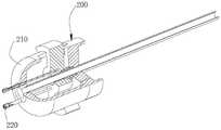
请参阅图2,本申请第一实施例的测力装置10包括壳体100、推送组件200及测力组件300,推送组件200位于壳体100的远端,测力组件100设置于壳体100。Referring to FIG. 2 , the
在一实施例中,壳体100与推送组件200固定连接。具体的,壳体100与推送组件200通过铆接固定连接,可以避免使用螺钉,拆装更加方便。In one embodiment, the
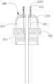
请一并参阅图3、图4及图6,推送组件200用于与心尖垫片13可释放地连接。推送组件200包括推送外壳210及接合件220,接合件220设置于推送外壳210上,且接合件220的外端伸出推送外壳210。推送外壳210与壳体固定连接。在本实施例中,推动外壳210与壳体100通过铆接固定连接。接合件220用于与心尖垫片13连接,心尖垫片13上设置有用于与接合件210连接的固定孔13a,接合件220的远端插设于固定孔13a,当心尖垫片13装载至接合件220后,接合件220的远端的尺寸大于固定孔13a,当接合件220释放心尖垫片13时,接合件220的远端的尺寸减小至从固定孔13a中脱离。Please refer to FIG. 3 , FIG. 4 and FIG. 6 together, the pushing
接合件220包括弹性管221及填充芯222,填充芯222的远端穿设于弹性管221,填充芯222滑动设置于弹性管221内。弹性管221固定设置于推送外壳210,且远端伸出推送外壳210,弹性管221的延伸方向与推送外壳210的中心轴平行,弹性管221的远端用于与心尖垫片13连接。当弹性管221的远端插设于心尖垫片13的固定孔13a时,弹性管221与心尖垫片13垂直连接,心尖垫片13与系绳12的延伸方向垂直,可以避免在手术过程中调整系绳12与心尖垫片13之间的夹角,降低手术难度,而且可以有助于提高后续对系绳12的张力值测定的准确性。The joint 220 includes an
在一实施例中,弹性管221为中空管,弹性管221的内径略大于填充芯222的外径,且在自然状态下,弹性管221的远端的最大外径大于固定孔13a的直径。填充芯222与弹性管221同轴设置。当填充芯222滑动至与弹性管221的远端齐平时,弹性管221的远端被撑开,弹性管221的远端直径大于固定孔13a,产生过盈配合,以将心尖垫片13固定在弹性管221的远端。当填充芯222向近端回撤时,弹性管221的远端直径变小至从固定孔13a中脱离,以将心尖垫片13从测力装置10上释放。在图示的实施例中,弹性管221的远端的直径略大于近端的直径。In one embodiment, the
在一实施例中,弹性管221的远端周壁上设置有多个缺口2211,缺口2211从弹性管221远离推送外壳210的一端开始并沿弹性管221的轴向方向延伸。通过设置缺口2211,弹性管221的远端插入到固定孔13a时,固定孔13a的孔壁会挤压弹性管221的远端,使得弹性管221的远端的最大外径减小。在一实施例中,缺口2211的数量为2-4个,多个缺口2211沿弹性管221的周向均匀分布。In one embodiment, a plurality of
请参阅图4,接合件220还包括推送块223,推送块223滑动设置于推送外壳210,填充芯222固定设置于推送块223,且填充芯222的远端伸出推送块223。在一实施例中,推送外壳210的侧壁上设置有滑轨211,推送块223滑动设置于滑轨223内。当推送块223沿着滑轨211轴向时,带动填充芯222在弹性管221内腔内轴向移动。Referring to FIG. 4 , the engaging
请一并参阅图4,推送外壳210内还设置有弹簧213,推送块223与弹簧连接。弹簧213设置于推送外壳210近端的位置,推送块223的远端与弹簧213的近端抵接。在自然状态下,推送块223位于滑轨211的远端,填充芯222的远端处于弹性管221的远端,如填充芯222的远端与弹性管221的远端齐平或稍超出弹性管221的远端。请一并参阅图6,当需要与心尖垫片13连接时,将推送块223沿滑轨211向近端移动,弹簧213被压缩,填充芯222的远端离开弹性管221的远端,弹性管221的远端插入到心尖垫片13的固定孔13a,此时松开推送块223,在弹簧213的作用下,推送块回复到滑轨211的近端,填充芯222的远端回复到弹性管221的远端将弹性管221的远端撑开,弹性管221的远端与固定孔13a产生过盈配合以将心尖垫片固定在弹性管221的远端。释放时,向近端拉动推送块223,填充芯222的远端再次离开弹性管221的远端,弹性管221的远端直径变小,心尖垫片13的固定孔13a从弹性管221的远端脱离。上述推送组件200,可以防止输送过程中心尖垫片13从测力装置10上脱落,而且还可以避免在释放过程中心尖垫片13无法从测力装置10上脱离。在本实施例中,弹簧213位于推送外壳210的中轴线上。Please also refer to FIG. 4 , a
请一并参阅图5及图6,在一实施例中,心尖垫片13设置有两个固定孔13a及用于供系绳12穿过的中心孔13b,两个固定孔13a对称设置于中心孔13b的两侧。固定孔13a为盲孔,中心孔13b为通孔。弹性管221及填充芯222的数量也均为2个,每一弹性管221对应连接一个固定孔13a。Please refer to FIG. 5 and FIG. 6 together. In one embodiment, the
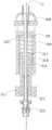
请一并参阅图7至图9,测力组件300包括调节螺杆310及滑动设置于调节螺杆310内的系绳调节件320,所述系绳12依次穿过心尖垫片13、推送组件200、壳体100及调节螺杆310,并从系绳调节件320穿出,调节螺杆310的远端可活动设置于壳体100内,调节螺杆310相对于壳体100向近端移动以带动系绳调节件320向近端移动,此时穿过系绳调节件320的系绳12拉动系绳调节件320向远端移动以调节和测定穿过系绳调节件320的系绳12的张力。Please refer to FIG. 7 to FIG. 9 together. The
请参阅图2,壳体100的外侧设置有防滑条纹,便于操作者握住。在一实施例中,壳体100内壁设置有内螺纹101,调节螺杆310的远端设置有与内螺纹101匹配的外螺纹311,调节螺杆310与壳体100通过外螺纹311与内螺纹301连接。当旋转调节螺杆310,调节螺杆310会相对于壳体100向近端或远端移动。Please refer to FIG. 2 , the outer side of the
调节螺杆310为中空结构,系绳调节件320滑动设置于调节螺杆310的空腔中。调节螺杆310还设置有弹性件313,系绳调节件320与弹性件313连接。The adjusting
在一实施例中,系绳调节件320包括滑动轴321、穿设于滑动轴321内的系绳收容管322及设置于滑动轴321远端的系绳锁定件323。滑动轴321套设在系绳收容件322上,且滑动轴321与系绳收容件322之间可以轴向滑动。系绳12依次穿过系绳收容管322、滑动轴321,最后从系绳锁定件323穿出。In one embodiment, the
需要说明的是,系绳收容管322的近端可以与滑动轴321齐平,此时,系绳12只需要穿过系绳收容管322并从系绳锁定件323穿出。It should be noted that the proximal end of the
滑动轴321的近端滑动设置于调节螺杆310内,且滑动轴321的远端与弹性件313的近端固定连接,弹性件321套设于系绳收容管322。当滑动轴321向近端移动时,弹性件313被压缩。滑动轴321上设置有刻度(图未标),滑动轴321与调节螺杆310之间的相对位置会通过刻度显示出拉力值。The proximal end of the sliding
在一实施例中,调节螺杆310的近端设置有限位结构314以将滑动轴321的远端限定在调节螺杆310内。具体的,调节螺杆310的近端的内径小于滑动轴321的远端的外径,滑动轴321的远端不能从调节螺杆310的近端脱离,防止操作过程中滑动轴321从调节螺杆310内脱离。In one embodiment, the proximal end of the adjusting
在一实施例中,系绳收容管322为中空管,用于收容系绳12。系绳收容管322贯通滑动轴313、调节螺杆310、壳体100,并延伸至推送组件200,系绳12通过系绳收容管322穿设推送组件200、壳体100及调节螺杆310。在本实施例中,系绳收容管322可以为镍钛管、钢管或其他金属管等,也可以为塑料等非金属管。In one embodiment, the
系绳锁定件323用于将系绳12夹紧。请一并参阅10及图11,系绳锁定件323包括底座3231、夹头3232及压盖3233,底座3231与滑动轴321的远端连接,底座3231与压盖3233螺纹连接,夹头3232设置于底座3231与压盖3233之间,底座3231、夹头3232及压盖3233均设置供系绳12穿过的通孔3234,系绳12从底座3231、夹头3232及压盖3233的通孔3234穿出,当压盖3233与底座3231旋紧时,夹头3232的通孔3234的内径减小以将系绳12夹紧。具体的,底座3231上设置有外螺纹,压盖3233为中空结构,内侧具有斜面,且内表面具有与底座3231的外螺纹匹配的内螺纹。夹头3232为管状结构,周壁上设置有开槽,当压盖3233与底座3231旋紧时会挤压位于压盖3233与底座3231之间的夹头3232,使夹头3232的内径减小,此时系绳12被夹头3232夹紧。
请参阅图8,在自然状态下,将系绳12穿过系绳收容管322、滑动轴313,并通过系绳锁定件323穿出,将系绳12保持拉直的状态,并通过系绳锁定件323固定系绳12的长度,此时调节螺杆310的远端位于壳体100靠远端的位置,滑动轴321的远端位于调节螺杆310靠近近端的位置,弹性件313处于自然伸展状态。请一并参阅图9,旋转调节螺杆310使调节螺杆310向壳体100的近端移动,调节螺杆310的移动会整体带动与调节螺杆310连接的滑动轴321及系绳锁定件323向近端移动,由于系绳12的长度被固定,此时系绳12会拉动滑动轴321向远端移动,使弹性件313被压缩,滑动轴移动321移动的距离即弹簧被压缩的长度,根据胡克定律,由此可以得出系绳12的张力值。Referring to FIG. 8 , in the natural state, the
使用时,将系绳12从心尖垫片13的中心孔13b穿出后,依次通过系绳收容管322、滑动轴313,并通过系绳锁定件323穿出;后撤推送块223,将弹簧管221的远端插设到心尖垫片13的固定孔13a,松开推送块223,以使心尖垫片13固定在弹性管221上,并将心尖垫片13输送至贴近心尖的位置;拉动系绳12,以使系绳12向近端拉直,即系绳12无打折弯曲等情况,通过系绳锁定件323锁定系绳12的长度;旋转调节螺杆310,以使调节螺杆310相对于壳体100向近端移动带动滑动轴321向近端移动,此时系绳12会拉动滑动轴321向远端移动,以压缩弹性件313,系绳12的力值显示在调节螺杆310的近端端面指向在滑动轴321外侧的数值。当调节螺杆310旋转至使系绳12达到合适的张力值,例如在超声检查下无瓣周漏的发生,将系绳12固定在心尖垫片13上,并撤去测力装置10。当然,在一实施例中,当调节好系绳12的张力值后,也可以先撤去测力装置10,再将系绳12固定在心尖垫片13上。In use, after passing the
请参阅图12至图14,本申请第二实施例的测力装置40包括手柄组件400、推送组件500、测力组件600,推送组件500位于手柄组件400的远端,测力组件500设置于手柄组件400。12 to 14 , the
在一实施例中,手柄组件400包括壳体410及设置于壳体410远离推送组件一端的系绳锁定件420。壳体410包括上壳体(图未标,与上壳体411对称设置)及下壳体411,上壳体与下壳体411通过铆合固定连接。系绳锁定件420卡合在壳体410的远端。In one embodiment, the
在一实施例中,壳体410的外表面设置有凸纹,便于操作者抓握,防止使用时打滑。In one embodiment, the outer surface of the
系绳锁定件420用于将系绳12夹紧。系绳锁定件420具体结构可以参照实施例一中的系绳锁定件323,在此不再赘述。在本实施例中,系绳锁定件420的底座卡合在壳体410内。
推送组件500用于与心尖垫片13可释放地连接。推送组件500的具体结构可参照实施例一中的推送组件200,在此不再赘述。The
测力组件600分别穿设推送组件500及手柄组件400,测力组件600设置有供系绳12穿过的系绳通道601,系绳12依次穿过心尖垫片13、推送组件500、系绳通道601,并从手柄组件400穿出,手柄组件400可相对于测力组件600轴向运动以调节和测定延伸穿过系绳通道601及手柄组件400的系绳12的张力。The
需要说明的是,测力组件600的系绳通道601可延伸至推送组件500的远端,系绳601通过系绳通道601穿设推送组件500。It should be noted that the
在一实施例中,测力组件600包括固定杆610及套设于固定杆610上的弹性件620。固定杆610上设置有系绳通道601,弹性件620收容于壳体410内,壳体410可相对于固定杆610轴向运动。在一实施例中,固定杆610位于壳体410的中轴线上,固定杆610的近端收容于壳体410内,弹性件620位于壳体410的远端与固定杆610的近端之间。In one embodiment, the
固定杆610与推送组件500固定连接。固定杆610可延伸至推送组件500的远端。固定杆610为中空管状结构,腔体为供系绳12穿过的系绳通道601。固定杆610可以包括金属管及包裹在金属管外的塑料管,金属管延伸至推送组件500的端部,塑料管结构可仅延伸至与推送组件500的近端固定连接。The fixing
请一并参阅图13及图14,壳体410的内壁设置有多个平行设置的凹槽413,固定杆610上设置有止挡件613,弹性件620位于止挡件613的远端与壳体410的远端之间,止挡件613可相对于壳体410转动,当止挡件613转动至卡合在凹槽413内,壳体410相对于固定杆610的位置固定,即壳体410不能相对于固定杆610轴向移动。具体的,止挡件613为凸设于固定杆610表面的凸块,凸块与凹槽413相匹配。请参阅图13,当凸块在水平状态时,即凸块与凹槽413深度方向呈90°时,壳体410可相对于固定杆610轴向运动。请参阅图14,将固定杆610转动90°,凸块与凹槽413卡合,壳体410与固定杆610之间不再发生轴向运动。Please refer to FIG. 13 and FIG. 14 together, the inner wall of the
在一实施例中,固定杆610的外表面设置有刻度(图未示),用于显示出系绳12的张力值。In one embodiment, the outer surface of the fixing
在使用时,将系绳12从心尖垫片13的中心孔13b穿出后,依次通过系绳通道601、壳体410,并通过系绳锁定件420穿出;将心尖垫片13固定在推送组件500上(具体过程可参照实施例一将心尖垫片固定至弹性管的过程),并将心尖垫片13输送至贴近心尖的位置;拉动系绳12,以使系绳12向近端拉直,即系绳12无打折弯曲等情况,通过系绳锁定件420锁定系绳12的长度;将壳体410向近端移动,此时弹性件620被压缩,当壳体410移动至使系绳12达到合适的张力值,例如在超声检查下无瓣周漏的发生,将壳体410相对于固定杆610旋转90°至止挡件613卡合在凹槽413内,此时系绳12的力值显示在壳体410的远端端面指向在固定杆610外侧的数值。将系绳12固定在心尖垫片13上,并撤去测力装置40。当然,在一实施例中,当调节好系绳12的张力值后,也可以先撤去测力装置40,再将系绳12固定在心尖垫片13上。In use, after passing the
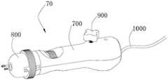
请参阅图15至图18,本申请第三实施例的测力装置70包括手柄组件700、推送组件800、系绳固定件900及测力装置1000,推送组件800位于手柄组件700的远端,系绳固定组件900及测力装置1000设置在手柄组件700的近端。15 to 18 , the
在一实施例中,手柄组件700包括壳体710及转动设置于壳体710上的旋钮720。具体的,壳体710上设置有收容槽711,旋钮720收容于收容槽711内,旋钮720能在收容槽711内转动。旋钮720的外侧设置有防滑纹路。In one embodiment, the
推送组件800用于与心尖垫片13可释放地连接。推送组件800的具体结构可参照实施例一中的推送组件200,在此不再赘述。The
系绳固定组件900用于将系绳12夹紧。请参阅图16至图18,系绳固定组件900包括固定座910、压块920及压杆930,固定座910设置于手柄组件700内,系绳12穿过所述固定座910,压块920与压杆930固定连接,压杆930与固定座910活动连接,压杆930带动压块920朝向固定座910移动以将穿过固定座910的系绳12夹紧。Tether securing
在一实施例中,固定座910上设置有供系绳12通过的通槽911,通槽911位于固定座910的中轴线上,通槽911的上部为方形,通槽911的底部为半圆弧形。压块920滑动设置于通槽911的侧壁,且与通槽911的侧壁接触,压块920的底部与通槽911的底部的形状匹配。当压块920在固定座910的通槽911中移动到底部时,两者完全吻合,通过这样的结构,可以将系绳12锁定在固定座910上。通槽911的底部为半圆弧形的设计,可以使得压块920在向下移动的过程中,系绳12最终推向通槽911的底部,减小系绳12与通槽911的底部的缝隙,避免系绳12在固定后被移动。In one embodiment, the fixing
固定座910的顶部设置有螺纹孔,压杆930上设置有与螺纹孔匹配的螺纹结构,压杆930穿设于螺纹孔,并与固定座910的螺纹孔螺纹连接。压杆930的底部与压块920固定连接,当旋转压杆930,压块920会朝向或远离固定座910移动,从而将系绳12锁定或松开。The top of the fixing
在一实施例中,系绳固定组件900还包括设置于固定座910近端的延伸管940,延伸管940用于将系绳12引出到手柄组件100的外侧。延伸管940的一端与通槽911连通,另一端伸出手柄组件700外。在图示的实施例中,延伸管940为圆弧形的管。In one embodiment, the
测力组件1000包括螺旋轴1010及设置于螺旋轴1010近端的测力传感器1020。螺旋轴1010的远端与推送组件800连接,螺旋轴1010的近端滑动设置于手柄组件700,螺旋轴1010内设置有用于系绳12穿过的系绳通道1011。测力传感器1020设置于手柄组件700内,测力传感器1020与系绳固定组件900连接。手柄组件700能够相对于螺旋轴1010轴向移动以调节穿过螺旋轴1010的系绳通道1011的系绳12的张力,测力传感器1020用于测定系绳的张力。The
在一实施例中,螺旋轴1010滑动设置于壳体710内。具体的,壳体710内设置有滑槽712,螺旋轴1010的近端设置有凸起1012,凸起1012滑动设置于滑槽712内。在图示的实施例中,壳体710内设置有两条平行的滑槽712,螺旋轴1010的近端设置有两个凸起1012,两个凸起1012分别在两个平行的滑槽712中轴向滑动。滑槽712的长度可以为10cm,凸起1012可以在滑槽712内滑动的距离为0-10cm。In one embodiment, the
在一实施例中,螺旋轴1010位于手柄组件700的中轴线上。螺旋轴1010的远端与推送组件800固定连接。具体的,螺旋轴1010与推送组件800通过锚定连接。螺旋轴1010具有中空的腔体,该腔体为用于系绳12穿过的系绳通道1011。螺旋轴1010的外侧具有外螺纹1014,旋钮720的内侧具有相匹配的内螺纹(图未示),螺旋轴1010与旋钮720通过外螺纹1014与内螺纹连接。当转动旋钮720时,螺旋轴1010可以轴向移动。In one embodiment, the
测力传感器1020固定设置于壳体710内。测力传感器1020与系绳固定组件900固定连接。在一实施例中,测力传感器1020与固定座910固定连接。测力传感器1020上还连接有连接线1021,连接线1021远离测力传感器1020的一端伸出壳体710,连接线1021用于连接外部显示器。测力传感器70的结构可以参照现有技术,在此不再赘述。The
在使用时,将系绳12从心尖垫片13的中心孔13b穿出后,依次通过系绳通道1011、壳体710,并通过系绳固定组件900穿出;将心尖垫片13固定在推送组件800上(具体过程可参照实施例一将心尖垫片固定至弹性管的过程),并将心尖垫片13输送至贴近心尖的位置;拉动系绳12,以使系绳12向近端拉直,即系绳12无打折弯曲等情况,通过系绳固定组件900锁定系绳12的长度;转动旋钮720使壳体710相对于螺旋轴1010移动,系绳12的张力值被调节,系绳12的力值可以被测力传感器测出;当壳体710移动至使使系绳12达到合适的张力值,例如在超声检查下无瓣周漏的发生,将系绳12固定在心尖垫片13上,并撤去测力装置70。当然,在一实施例中,当调节好系绳12的张力值后,也可以先撤去测力装置70,再将系绳12固定在心尖垫片13上。In use, after passing the
以上所述实施例的各技术特征可以进行任意的组合,为使描述简洁,未对上述实施例中的各个技术特征所有可能的组合都进行描述,然而,只要这些技术特征的组合不存在矛盾,都应当认为是本说明书记载的范围。The technical features of the above-described embodiments can be combined arbitrarily. For the sake of brevity, all possible combinations of the technical features in the above-described embodiments are not described. However, as long as there is no contradiction between the combinations of these technical features, All should be regarded as the scope described in this specification.
以上所述实施例仅表达了本发明的几种实施方式,其描述较为具体和详细,但并不能因此而理解为对发明专利范围的限制。应当指出的是,对于本领域的普通技术人员来说,在不脱离本发明构思的前提下,还可以做出若干变形和改进,这些都属于本发明的保护范围。因此,本发明专利的保护范围应以所附权利要求为准。The above-mentioned embodiments only represent several embodiments of the present invention, and the descriptions thereof are specific and detailed, but should not be construed as a limitation on the scope of the invention patent. It should be pointed out that for those skilled in the art, without departing from the concept of the present invention, several modifications and improvements can be made, which all belong to the protection scope of the present invention. Therefore, the protection scope of the patent of the present invention should be subject to the appended claims.
Claims (10)
Translated fromChinesePriority Applications (1)
| Application Number | Priority Date | Filing Date | Title |
|---|---|---|---|
| CN201911379148.XACN111067667B (en) | 2019-12-27 | 2019-12-27 | Force measuring device and pushing assembly thereof |
Applications Claiming Priority (1)
| Application Number | Priority Date | Filing Date | Title |
|---|---|---|---|
| CN201911379148.XACN111067667B (en) | 2019-12-27 | 2019-12-27 | Force measuring device and pushing assembly thereof |
Publications (2)
| Publication Number | Publication Date |
|---|---|
| CN111067667A CN111067667A (en) | 2020-04-28 |
| CN111067667Btrue CN111067667B (en) | 2022-04-22 |
Family
ID=70318673
Family Applications (1)
| Application Number | Title | Priority Date | Filing Date |
|---|---|---|---|
| CN201911379148.XAActiveCN111067667B (en) | 2019-12-27 | 2019-12-27 | Force measuring device and pushing assembly thereof |
Country Status (1)
| Country | Link |
|---|---|
| CN (1) | CN111067667B (en) |
Families Citing this family (2)
| Publication number | Priority date | Publication date | Assignee | Title |
|---|---|---|---|---|
| CN114681132B (en)* | 2020-12-29 | 2025-08-12 | 杭州德晋医疗科技有限公司 | Heart valve repair device |
| CN114886611B (en)* | 2022-04-22 | 2025-07-08 | 上海形状记忆合金材料有限公司 | Clamp and device for testing recovery stress of implant |
Citations (10)
| Publication number | Priority date | Publication date | Assignee | Title |
|---|---|---|---|---|
| JPH0767793A (en)* | 1993-09-02 | 1995-03-14 | Tadatoshi Yanagida | Metallic vacuum bottle, production method of metallic vacuum bottle, metallic vacuum bottle produced by metallic vacuum bottle production method |
| CN1143326A (en)* | 1994-03-10 | 1997-02-19 | 巴伐利亚医学技术有限公司 | Catheters for injecting fluids or medications |
| CN1780599A (en)* | 2003-04-28 | 2006-05-31 | 住友电木株式会社 | catheter set for fistula |
| CN102195154A (en)* | 2010-03-05 | 2011-09-21 | 丰田铁工株式会社 | Press-fit terminal |
| CN102497906A (en)* | 2009-07-14 | 2012-06-13 | 爱德华兹生命科学公司 | Apical delivery system for heart valves |
| CN103124578A (en)* | 2010-06-25 | 2013-05-29 | 史密斯医疗Asd公司 | Conduit assembly with seal |
| CN204436322U (en)* | 2015-02-27 | 2015-07-01 | 毛元伟 | Packer elasticity packing element |
| CN109602524A (en)* | 2018-10-25 | 2019-04-12 | 先健科技(深圳)有限公司 | Fixtures for interventional medical devices |
| CN110338911A (en)* | 2014-03-10 | 2019-10-18 | 坦迪尼控股股份有限公司 | Device and method for positioning and monitoring the tether load of prosthetic mitral valve |
| CN209800482U (en)* | 2019-02-20 | 2019-12-17 | 上海艾弗森建设工程有限公司 | High-efficient heat preservation nail |
Family Cites Families (8)
| Publication number | Priority date | Publication date | Assignee | Title |
|---|---|---|---|---|
| US5098369A (en)* | 1987-02-27 | 1992-03-24 | Vascor, Inc. | Biocompatible ventricular assist and arrhythmia control device including cardiac compression pad and compression assembly |
| US7213643B2 (en)* | 2003-04-23 | 2007-05-08 | Halliburton Energy Services, Inc. | Expanded liner system and method |
| US7431692B2 (en)* | 2006-03-09 | 2008-10-07 | Edwards Lifesciences Corporation | Apparatus, system, and method for applying and adjusting a tensioning element to a hollow body organ |
| US10500038B1 (en)* | 2011-05-20 | 2019-12-10 | Tel Hashomer Medical Research Infrastructure And Services Ltd. | Prosthetic mitral valve, and methods and devices for deploying the prosthetic mitral valve |
| WO2015058039A1 (en)* | 2013-10-17 | 2015-04-23 | Robert Vidlund | Apparatus and methods for alignment and deployment of intracardiac devices |
| CN109247959B (en)* | 2017-07-13 | 2020-07-03 | 先健科技(深圳)有限公司 | Plugging device pushing device and conveying system |
| CN109199468B (en)* | 2018-06-08 | 2024-07-02 | 杭州德晋医疗科技有限公司 | Adjustable heart valve repair system |
| CN208800816U (en)* | 2018-07-06 | 2019-04-30 | 柴建平 | A kind of coal production drilling equipment |
- 2019
- 2019-12-27CNCN201911379148.XApatent/CN111067667B/enactiveActive
Patent Citations (10)
| Publication number | Priority date | Publication date | Assignee | Title |
|---|---|---|---|---|
| JPH0767793A (en)* | 1993-09-02 | 1995-03-14 | Tadatoshi Yanagida | Metallic vacuum bottle, production method of metallic vacuum bottle, metallic vacuum bottle produced by metallic vacuum bottle production method |
| CN1143326A (en)* | 1994-03-10 | 1997-02-19 | 巴伐利亚医学技术有限公司 | Catheters for injecting fluids or medications |
| CN1780599A (en)* | 2003-04-28 | 2006-05-31 | 住友电木株式会社 | catheter set for fistula |
| CN102497906A (en)* | 2009-07-14 | 2012-06-13 | 爱德华兹生命科学公司 | Apical delivery system for heart valves |
| CN102195154A (en)* | 2010-03-05 | 2011-09-21 | 丰田铁工株式会社 | Press-fit terminal |
| CN103124578A (en)* | 2010-06-25 | 2013-05-29 | 史密斯医疗Asd公司 | Conduit assembly with seal |
| CN110338911A (en)* | 2014-03-10 | 2019-10-18 | 坦迪尼控股股份有限公司 | Device and method for positioning and monitoring the tether load of prosthetic mitral valve |
| CN204436322U (en)* | 2015-02-27 | 2015-07-01 | 毛元伟 | Packer elasticity packing element |
| CN109602524A (en)* | 2018-10-25 | 2019-04-12 | 先健科技(深圳)有限公司 | Fixtures for interventional medical devices |
| CN209800482U (en)* | 2019-02-20 | 2019-12-17 | 上海艾弗森建设工程有限公司 | High-efficient heat preservation nail |
Also Published As
| Publication number | Publication date |
|---|---|
| CN111067667A (en) | 2020-04-28 |
Similar Documents
| Publication | Publication Date | Title |
|---|---|---|
| CN107837105B (en) | Puncture catheters and tissue tightening systems | |
| CN111067667B (en) | Force measuring device and pushing assembly thereof | |
| CN111920549A (en) | Clip body of mitral valve clamping device, mitral valve clamping device and repair equipment | |
| CN104083214B (en) | Bend-adjustable medical catheter and assembling method thereof | |
| CN111035475B (en) | Force measuring device | |
| CN104983485B (en) | Valve connecting mechanism of heart valve conveying device | |
| CN111481251B (en) | Fastening nail and fastening nail implantation device | |
| CN110916852B (en) | An outer tube moving mechanism and a valve delivery device | |
| CN115245407B (en) | Transfemoral valve repair delivery device | |
| CN110638488A (en) | Connect reliable implant pushers and implant delivery systems | |
| CN111803166A (en) | Occluder and occluder locking system | |
| CN108309511B (en) | Interventional valve loading device | |
| CN111012549B (en) | Force measuring device | |
| CN111467083A (en) | A delivery tube of a tissue clamping device and valve repair equipment | |
| WO2020134539A1 (en) | Conveyor and conveyor system | |
| CN111067668B (en) | Force measuring device | |
| CN211834542U (en) | Control handle, valve suture device and valve suture system | |
| US11399844B2 (en) | Medical device holding and delivery assembly and kit therefor | |
| CN110638489A (en) | Quick release implant pusher and implant delivery system | |
| WO2020207485A1 (en) | Occluder and locking system of occluder | |
| CN117860434A (en) | Core wire control structure and mitral valve clamp | |
| US20230025774A1 (en) | Forward-pushing for releasing suture locking device | |
| CN115990077A (en) | Clamp Delivery Devices and Clamp Delivery Systems | |
| CN115998485A (en) | Adjustable sheath and clamp delivery device | |
| CN211723554U (en) | filler syringe |
Legal Events
| Date | Code | Title | Description |
|---|---|---|---|
| PB01 | Publication | ||
| PB01 | Publication | ||
| SE01 | Entry into force of request for substantive examination | ||
| SE01 | Entry into force of request for substantive examination | ||
| GR01 | Patent grant | ||
| GR01 | Patent grant | ||
| TR01 | Transfer of patent right | ||
| TR01 | Transfer of patent right | Effective date of registration:20231222 Address after:518000 1604, Xianjian technology building, No. 22, Keji South 12th Road, gaoxinyuan community, Yuehai street, Nanshan District, Shenzhen, Guangdong Province Patentee after:Shenzhen Jianxin Medical Technology Co.,Ltd. Address before:518000 1st-5th Floor of Saiba Research Building, Langshan Second Road, North District of Nanshan High-tech Industrial Park, Shenzhen City, Guangdong Province Patentee before:LIFETECH SCIENTIFIC (SHENZHEN) Co.,Ltd. |