CN111067617A - Radiofrequency closed catheter and method of making the same - Google Patents
Radiofrequency closed catheter and method of making the sameDownload PDFInfo
- Publication number
- CN111067617A CN111067617ACN201911375916.4ACN201911375916ACN111067617ACN 111067617 ACN111067617 ACN 111067617ACN 201911375916 ACN201911375916 ACN 201911375916ACN 111067617 ACN111067617 ACN 111067617A
- Authority
- CN
- China
- Prior art keywords
- coil
- temperature measuring
- ring
- radiofrequency
- glue
- Prior art date
- Legal status (The legal status is an assumption and is not a legal conclusion. Google has not performed a legal analysis and makes no representation as to the accuracy of the status listed.)
- Pending
Links
Images


Classifications
- A—HUMAN NECESSITIES
- A61—MEDICAL OR VETERINARY SCIENCE; HYGIENE
- A61B—DIAGNOSIS; SURGERY; IDENTIFICATION
- A61B18/00—Surgical instruments, devices or methods for transferring non-mechanical forms of energy to or from the body
- A61B18/04—Surgical instruments, devices or methods for transferring non-mechanical forms of energy to or from the body by heating
- A61B18/12—Surgical instruments, devices or methods for transferring non-mechanical forms of energy to or from the body by heating by passing a current through the tissue to be heated, e.g. high-frequency current
- A61B18/14—Probes or electrodes therefor
- A61B18/1492—Probes or electrodes therefor having a flexible, catheter-like structure, e.g. for heart ablation
- A—HUMAN NECESSITIES
- A61—MEDICAL OR VETERINARY SCIENCE; HYGIENE
- A61M—DEVICES FOR INTRODUCING MEDIA INTO, OR ONTO, THE BODY; DEVICES FOR TRANSDUCING BODY MEDIA OR FOR TAKING MEDIA FROM THE BODY; DEVICES FOR PRODUCING OR ENDING SLEEP OR STUPOR
- A61M25/00—Catheters; Hollow probes
- A61M25/0021—Catheters; Hollow probes characterised by the form of the tubing
- A—HUMAN NECESSITIES
- A61—MEDICAL OR VETERINARY SCIENCE; HYGIENE
- A61M—DEVICES FOR INTRODUCING MEDIA INTO, OR ONTO, THE BODY; DEVICES FOR TRANSDUCING BODY MEDIA OR FOR TAKING MEDIA FROM THE BODY; DEVICES FOR PRODUCING OR ENDING SLEEP OR STUPOR
- A61M25/00—Catheters; Hollow probes
- A61M25/0043—Catheters; Hollow probes characterised by structural features
- A61M25/0045—Catheters; Hollow probes characterised by structural features multi-layered, e.g. coated
- A—HUMAN NECESSITIES
- A61—MEDICAL OR VETERINARY SCIENCE; HYGIENE
- A61M—DEVICES FOR INTRODUCING MEDIA INTO, OR ONTO, THE BODY; DEVICES FOR TRANSDUCING BODY MEDIA OR FOR TAKING MEDIA FROM THE BODY; DEVICES FOR PRODUCING OR ENDING SLEEP OR STUPOR
- A61M25/00—Catheters; Hollow probes
- A61M25/0043—Catheters; Hollow probes characterised by structural features
- A61M25/005—Catheters; Hollow probes characterised by structural features with embedded materials for reinforcement, e.g. wires, coils, braids
- A—HUMAN NECESSITIES
- A61—MEDICAL OR VETERINARY SCIENCE; HYGIENE
- A61M—DEVICES FOR INTRODUCING MEDIA INTO, OR ONTO, THE BODY; DEVICES FOR TRANSDUCING BODY MEDIA OR FOR TAKING MEDIA FROM THE BODY; DEVICES FOR PRODUCING OR ENDING SLEEP OR STUPOR
- A61M25/00—Catheters; Hollow probes
- A61M25/0043—Catheters; Hollow probes characterised by structural features
- A61M25/0054—Catheters; Hollow probes characterised by structural features with regions for increasing flexibility
- A—HUMAN NECESSITIES
- A61—MEDICAL OR VETERINARY SCIENCE; HYGIENE
- A61B—DIAGNOSIS; SURGERY; IDENTIFICATION
- A61B18/00—Surgical instruments, devices or methods for transferring non-mechanical forms of energy to or from the body
- A61B2018/00315—Surgical instruments, devices or methods for transferring non-mechanical forms of energy to or from the body for treatment of particular body parts
- A61B2018/00345—Vascular system
- A61B2018/00404—Blood vessels other than those in or around the heart
- A—HUMAN NECESSITIES
- A61—MEDICAL OR VETERINARY SCIENCE; HYGIENE
- A61B—DIAGNOSIS; SURGERY; IDENTIFICATION
- A61B18/00—Surgical instruments, devices or methods for transferring non-mechanical forms of energy to or from the body
- A61B2018/00636—Sensing and controlling the application of energy
- A61B2018/00696—Controlled or regulated parameters
- A61B2018/00714—Temperature
- A—HUMAN NECESSITIES
- A61—MEDICAL OR VETERINARY SCIENCE; HYGIENE
- A61M—DEVICES FOR INTRODUCING MEDIA INTO, OR ONTO, THE BODY; DEVICES FOR TRANSDUCING BODY MEDIA OR FOR TAKING MEDIA FROM THE BODY; DEVICES FOR PRODUCING OR ENDING SLEEP OR STUPOR
- A61M25/00—Catheters; Hollow probes
- A61M25/0043—Catheters; Hollow probes characterised by structural features
- A61M2025/0063—Catheters; Hollow probes characterised by structural features having means, e.g. stylets, mandrils, rods or wires to reinforce or adjust temporarily the stiffness, column strength or pushability of catheters which are already inserted into the human body
Landscapes
- Health & Medical Sciences (AREA)
- Life Sciences & Earth Sciences (AREA)
- Engineering & Computer Science (AREA)
- Heart & Thoracic Surgery (AREA)
- Biomedical Technology (AREA)
- Public Health (AREA)
- Veterinary Medicine (AREA)
- Animal Behavior & Ethology (AREA)
- General Health & Medical Sciences (AREA)
- Anesthesiology (AREA)
- Pulmonology (AREA)
- Surgery (AREA)
- Hematology (AREA)
- Biophysics (AREA)
- Otolaryngology (AREA)
- Molecular Biology (AREA)
- Medical Informatics (AREA)
- Physics & Mathematics (AREA)
- Nuclear Medicine, Radiotherapy & Molecular Imaging (AREA)
- Plasma & Fusion (AREA)
- Cardiology (AREA)
- Media Introduction/Drainage Providing Device (AREA)
Abstract
Description
Translated fromChinese技术领域technical field
本发明涉及一种介入治疗的医疗器械,特别涉及一种用于下肢浅静脉和交通静脉曲张治疗的射频闭合导管及其制作方法。The invention relates to a medical device for interventional therapy, in particular to a radiofrequency closed catheter for the treatment of superficial lower extremity veins and communicating varicose veins and a manufacturing method thereof.
背景技术Background technique
下肢静脉曲张是最常见的血管内疾病,以大隐静脉曲张最为多见。我国成年男女的患病率分别高达10%~15%与20%~25%,世界卫生组织最新统计结果显示,国内存在1亿以上人口患下肢静脉曲张,已成为国内各大基层医院的主要病种之一。下肢静脉曲张的临床表现为腿部皮肤表层血管像蚯蚓一样曲张,曲张呈团状或结节状,明显的凸出皮肤,其他主要症状包括皮肤色素沉着甚至溃疡、疼痛、肿胀、灼烧感和瘙痒等。静脉曲张的病理机制比较复杂,主要包括静脉壁薄弱、先天性静脉瓣缺损、浅静脉压力高、生活环境影响以及遗传等,是慢性静脉功能不全最明显的症状,它显著地影响着患者的生活质量及美观。Varicose veins of the lower extremities are the most common endovascular diseases, and varicose veins of the great saphenous vein are the most common. The prevalence rates of adult men and women in my country are as high as 10% to 15% and 20% to 25% respectively. The latest statistics of the World Health Organization show that there are more than 100 million people suffering from lower extremity varicose veins in China, which has become a major disease in major domestic hospitals. one of the species. The clinical manifestations of varicose veins of the lower extremities are varicose veins on the skin surface of the legs like earthworms, varicose lumps or nodules, and obvious protruding skin. Other main symptoms include skin pigmentation and even ulcers, pain, swelling, burning and itching, etc. The pathological mechanism of varicose veins is complex, mainly including weak venous wall, congenital venous valve defect, high superficial venous pressure, influence of living environment and heredity, etc. It is the most obvious symptom of chronic venous insufficiency, which significantly affects the life of patients. Quality and beauty.
下肢静脉曲张的治疗包括保守治疗、注射硬化剂以及手术治疗三大类。保守治疗适用于程度较轻、无明显症状的发病,方法包括压力袜、弹力绷带、充气加压等,也包括服用纤维蛋白分解药物、前列腺素E1等药物进行治疗。注射硬化治疗是指通过硬化剂注射定向祛除曲张静脉以及使静脉畸形患者筋膜下的曲张血管硬化,使静脉转化为纤维条索,其功效相当于曲张静脉的外科切除术,主要应用于较轻的症状以及手术后辅助治疗。注射治疗会伴随一些诸如药液外渗、血栓形成伴疼痛、过敏反应、深静脉血栓等在内的并发症。The treatment of lower extremity varicose veins includes three categories: conservative treatment, injection of sclerotherapy, and surgical treatment. Conservative treatment is suitable for mild cases with no obvious symptoms. Methods include compression stockings, elastic bandages, pneumatic compression, etc., as well as taking fibrinolytic drugs, prostaglandin E1 and other drugs for treatment. Injection sclerotherapy refers to the directional removal of varicose veins through sclerotherapy injection and the sclerosis of the varicose vessels under the fascia in patients with venous malformations, so that the veins are transformed into fibrous cords. The effect is equivalent to the surgical resection of varicose veins. symptoms and post-operative adjuvant therapy. Injection therapy is accompanied by complications such as drug extravasation, thrombosis with pain, allergic reactions, and deep vein thrombosis.
微创手术治疗由于具有创伤小、切口美观及并发症少等优点,目前已经成为治疗静脉曲张有效的外科手段,通过微创治疗下肢静脉曲张已经成为一种趋势。能够治疗下肢静脉曲张的微创手术包括电凝术、刨吸术、激光治疗和射频消融术。与其他微创手术相比,射频消融治疗在患者疼痛缓解、生活质量及恢复速度方面更具优势,患者术后即可正常活动,同时术后复发率较低,术后并发症少,几乎不需要特殊的止痛药物。Minimally invasive surgery has become an effective surgical method for the treatment of varicose veins due to its advantages of small trauma, beautiful incision and fewer complications. Minimally invasive treatment of lower extremity varicose veins has become a trend. Minimally invasive procedures that can treat varicose veins in the lower extremities include electrocoagulation, suction, laser therapy, and radiofrequency ablation. Compared with other minimally invasive surgeries, radiofrequency ablation has more advantages in terms of pain relief, quality of life and recovery speed. Special pain medication is required.
目前的射频消融治疗仍然存在一些需改进的方面,例如在下肢浅静脉和交通静脉的射频消融治疗中,由于浅静脉和交通静脉手术中需要使用不同的器械,导致产生器械更换的风险,而且延长了手术时间。There are still some areas for improvement in the current radiofrequency ablation. For example, in the radiofrequency ablation of the superficial veins and communicating veins of the lower extremities, different instruments are required in the superficial vein and communicating vein operations, resulting in the risk of instrument replacement and prolonged operation time.
发明内容SUMMARY OF THE INVENTION
本发明提供一种射频闭合导管及其制作方法,可以在无需更换器械的情况下实现下肢浅静脉曲张和交通静脉曲张两种病变部位的射频消融,远端线圈单独作用于交通静脉曲张的治疗,远端线圈和近端线圈联合用于下肢浅静脉曲张的治疗,避免了器械更换的风险,而且缩短了手术时间。The invention provides a radiofrequency closed catheter and a manufacturing method thereof, which can realize radiofrequency ablation of two diseased parts of lower extremity superficial varicose veins and communicating varicose veins without changing instruments, and the distal coil alone acts on the treatment of communicating varicose veins. The distal coil and the proximal coil are combined for the treatment of superficial varicose veins of the lower extremity, which avoids the risk of instrument replacement and shortens the operation time.
本发明的技术方案如下:The technical scheme of the present invention is as follows:
一种射频闭合导管,其主要包括:A radiofrequency closed catheter, which mainly includes:
从远端至近端顺序连接的管身、手柄装置、连接线缆和连接器,其中,所述管身从远端开始顺序设有胶头、发热段和主体管,并且,所述发热段的表面设有具有绝缘和光滑作用的绝缘外套管,所述发热段的内部设有用于加热的、由合金丝绕制而成的线圈,所述线圈包括近端线圈和远端线圈,所述近端线圈和远端线圈至少其中之一为4.0cm以下的短宽度,所述近端线圈和远端线圈各自的延长线分别经过所述主体管的内腔延伸至所述手柄装置,并通过所述连接线缆连接至所述连接器,所述连接器连接外部设备以提供射频电流。A tube body, a handle device, a connecting cable and a connector are sequentially connected from the distal end to the proximal end, wherein the tube body is sequentially provided with a rubber head, a heating section and a main body tube from the distal end, and the heating section is The surface of the heater is provided with an insulating outer sleeve with insulating and smoothing functions, and the inside of the heating section is provided with a coil made of alloy wire for heating. The coil includes a proximal coil and a distal coil. At least one of the proximal coil and the distal coil has a short width of less than 4.0 cm, and the respective extension lines of the proximal coil and the distal coil respectively extend to the handle device through the lumen of the main body tube, and pass through The connection cable is connected to the connector, and the connector is connected to an external device to provide radio frequency current.
在优选的实施方式中,所述近端线圈和所述远端线圈的总宽度相同或不同。In preferred embodiments, the proximal and distal coils have the same or different overall widths.
在优选的实施方式中,所述远端线圈的总宽度为0.3-4.0cm,所述近端线圈的总宽度为4.0-8.0cm,所述远端线圈与所述近端线圈的间距为0-2mm;所述远端线圈和所述近端线圈各包括至少一段线圈。In a preferred embodiment, the total width of the distal coil is 0.3-4.0 cm, the total width of the proximal coil is 4.0-8.0 cm, and the distance between the distal coil and the proximal coil is 0 -2mm; the distal coil and the proximal coil each include at least one section of coil.
在优选的实施方式中,所述发热段还包括线圈内套管,所述远端线圈或近端线圈是由至少一根合金丝在中间位置对折之后,以对折点为起点,在所述线圈内套管上绕制而成,所述合金丝之间的间隙设计为0-0.15mm;所述线圈内套管上开有至少两个小孔,每根合金丝的延长线分别通过一个所述小孔穿入所述线圈内套管的内腔。In a preferred embodiment, the heating segment further comprises a coil inner sleeve, the distal coil or the proximal coil is folded in half by at least one alloy wire at the middle position, and the folded point is taken as the starting point. The inner sleeve is wound on the inner sleeve, and the gap between the alloy wires is designed to be 0-0.15mm; at least two small holes are opened on the inner sleeve of the coil, and the extension line of each alloy wire passes through a The small hole penetrates the inner cavity of the inner sleeve of the coil.
在优选的实施方式中,所述线圈内套管为单腔管,所述线圈内套管的制造材料选自聚醚醚酮或聚酰亚胺的一种;所述合金丝的材料为52合金,所述合金丝的表面具有聚酰亚胺绝缘涂层,所述合金丝的外径为0.1-0.2mm。In a preferred embodiment, the inner coil sleeve is a single-lumen tube, and the manufacturing material of the inner coil sleeve is selected from one of polyetheretherketone or polyimide; the material of the alloy wire is 52 Alloy, the surface of the alloy wire has a polyimide insulating coating, and the outer diameter of the alloy wire is 0.1-0.2mm.
在优选的实施方式中,所述合金丝绕制而成的线圈与所述线圈内套管采用胶水粘接固定。In a preferred embodiment, the coil formed by winding the alloy wire and the inner sleeve of the coil are bonded and fixed with glue.
在优选的实施方式中,还包括导丝管和导丝口,所述导丝管的一端从所述线圈内套管的远端开口穿入,依次穿入所述线圈内套管、主体管和手柄的内腔,并插入所述导丝口的远端内腔,使用胶水将所述导丝管与所述导丝口的接口粘接固定。In a preferred embodiment, a wire guide tube and a wire guide port are also included, and one end of the wire guide tube is inserted through the distal opening of the inner coil sleeve, and successively penetrates the inner coil sleeve and the main body tube. and the lumen of the handle, and insert it into the distal lumen of the guide wire port, and use glue to bond and fix the guide wire tube and the interface of the guide wire port.
在优选的实施方式中,每段所述远端线圈或近端线圈的中间位置留有0.5-3.0mm的未缠绕间隔,至少一个所述未缠绕间隔内设有测温装置,所述测温装置包括至少一个用于测量血管内壁温度的温度传感器。In a preferred embodiment, an unwinding interval of 0.5-3.0 mm is left in the middle of each segment of the distal coil or the proximal coil, and a temperature measuring device is provided in at least one of the unwinding intervals. The device includes at least one temperature sensor for measuring the temperature of the inner wall of the blood vessel.
在优选的实施方式中,所述测温装置还包括传导血管内壁温度的测温环,所述测温环固定在所述未缠绕间隔上。In a preferred embodiment, the temperature measurement device further comprises a temperature measurement ring that conducts the temperature of the inner wall of the blood vessel, and the temperature measurement ring is fixed on the unwound space.
在优选的实施方式中,所述温度传感器的测温头端设于所述未缠绕间隔内且不与所述线圈直接接触;所述温度传感器的延长线穿过所述线圈内套管上设置的穿线孔或穿过所述测温环及所述线圈内套管各自设置的穿线孔进入所述线圈内套管的内腔,并经过所述主体管的内腔、所述手柄、所述连接线缆连接到所述连接器。In a preferred embodiment, the temperature measuring head end of the temperature sensor is arranged in the unwinding interval and does not directly contact the coil; the extension wire of the temperature sensor is arranged on the inner sleeve of the coil through the The threading hole or through the threading hole respectively provided by the temperature measuring ring and the coil inner sleeve enters the inner cavity of the coil inner sleeve, and passes through the inner cavity of the main body tube, the handle, the A connecting cable is connected to the connector.
在优选的实施方式中,所述未缠绕间隔内,所述合金丝的走向沿所述射频闭合导管的轴向;所述测温环的形状为完整环或“C形”环;所述测温环的材料选自铂铱合金、铂金、黄金、不锈钢中的一种;所述测温环的内径为1.3-2.0mm,所述测温环的外径为1.4-2.1mm,所述测温环的宽度为0.5-2.5mm。In a preferred embodiment, in the unwinding interval, the direction of the alloy wire is along the axial direction of the radio frequency closed catheter; the shape of the temperature measurement ring is a complete ring or a "C-shaped" ring; The material of the temperature ring is selected from one of platinum-iridium alloy, platinum, gold, and stainless steel; the inner diameter of the temperature measurement ring is 1.3-2.0mm, the outer diameter of the temperature measurement ring is 1.4-2.1mm, and the temperature measurement ring is 1.4-2.1mm. The width of the warm ring is 0.5-2.5mm.
在优选的实施方式中,所述管身还包括胶头,所述胶头设于所述发热段的远端,所述胶头为环氧树脂胶水或UV胶水固化形成的圆形胶头。In a preferred embodiment, the tube body further includes a glue head, the glue head is disposed at the distal end of the heating section, and the glue head is a circular glue head formed by curing epoxy resin glue or UV glue.
在优选的实施方式中,所述主体管为多层单腔编织管。In a preferred embodiment, the main body tube is a multi-layer single lumen braided tube.
基于同样的发明构思,本发明还提供一种射频闭合导管,其包括靠近远端的发热段,所述发热段包括能够与电源连接的、用于加热的、由合金丝绕制而成的线圈,所述线圈包括分别与所述电源连接的近端线圈和远端线圈,所述近端线圈和所述远端线圈的宽度相同或不同。Based on the same inventive concept, the present invention also provides a radiofrequency closed catheter, which includes a heating section near the distal end, and the heating section includes a coil that can be connected to a power source and used for heating and is made of alloy wire. , the coil includes a proximal coil and a distal coil respectively connected with the power source, and the width of the proximal coil and the distal coil are the same or different.
基于同样的发明构思,本发明还提供一种上述的射频闭合导管的制作方法,包括所述测温装置的如下制作方法步骤:Based on the same inventive concept, the present invention also provides a manufacturing method of the above-mentioned radiofrequency closed catheter, including the following manufacturing method steps of the temperature measuring device:
在线圈内套管上每段线圈的未缠绕间隔的中间位置设置并固定“C形”环,“C形”环的两侧边缘不与合金丝接触,“C形”环的横截开口位于合金丝沿导管轴向设置的直段部分的两侧,且不与合金丝接触;在“C形”环的近端一侧与合金丝间隙的线圈内套管表面开设穿线孔,使用胶水固定温度传感器的头端在“C形”环的外表面中心位置,温度传感器的延长线通过所述穿线孔穿入线圈内套管的内腔,经过主体管的内腔、手柄、连接线缆连接到连接器。A "C-shaped" ring is set and fixed in the middle of the unwinding interval of each coil on the inner sleeve of the coil, the two edges of the "C-shaped" ring are not in contact with the alloy wire, and the cross-sectional opening of the "C-shaped" ring is located at The alloy wire is arranged on both sides of the straight section along the axial direction of the catheter, and is not in contact with the alloy wire; a threading hole is opened on the surface of the coil inner sleeve between the proximal end side of the "C-shaped" ring and the alloy wire gap, and glue is used to fix it The head end of the temperature sensor is at the center of the outer surface of the "C-shaped" ring, and the extension wire of the temperature sensor penetrates the inner cavity of the coil inner sleeve through the threading hole, and is connected through the inner cavity of the main tube, the handle, and the connecting cable. to the connector.
基于同样的发明构思,本发明还提供一种上述的射频闭合导管的制作方法,包括所述测温装置的如下制作方法步骤:Based on the same inventive concept, the present invention also provides a manufacturing method of the above-mentioned radiofrequency closed catheter, including the following manufacturing method steps of the temperature measuring device:
在线圈内套管上每段线圈的未缠绕间隔的中间位置开设穿线孔,同时温度传感器的头端使用胶水固定在线圈内套管表面未缠绕间隔的中间位置,温度传感器的延长线穿入线圈内套管表面的所述穿线孔进入线圈内套管的内腔,经过主体管的内腔、手柄、连接线缆直至连接到连接器;A threading hole is provided in the middle of the unwinding interval of each coil on the inner casing of the coil, and the head end of the temperature sensor is fixed at the middle position of the unwinding interval on the surface of the inner casing of the coil with glue, and the extension wire of the temperature sensor is inserted into the coil. The threading hole on the surface of the inner sleeve enters the inner cavity of the coil inner sleeve, passes through the inner cavity of the main body tube, the handle, and the connecting cable until it is connected to the connector;
在线圈的未缠绕间隔套入完整的测温环,保持测温环完全的覆盖住温度传感器的头端,且测温环的两侧不与两边合金丝接触,使用胶水填封测温环与线圈内套管的间隙,以固定测温装置。Put a complete temperature measuring ring in the unwinding interval of the coil, keep the temperature measuring ring completely covering the head end of the temperature sensor, and the two sides of the temperature measuring ring are not in contact with the alloy wires on both sides, use glue to seal the temperature measuring ring and The gap between the inner casing of the coil to fix the temperature measuring device.
基于同样的发明构思,本发明还提供一种上述的射频闭合导管的制作方法,包括所述测温装置的如下制作方法步骤:Based on the same inventive concept, the present invention also provides a manufacturing method of the above-mentioned radiofrequency closed catheter, including the following manufacturing method steps of the temperature measuring device:
在线圈内套管上预先确定好测温装置的位置,在该位置的线圈内套管表面使用胶水固定完整的测温环,在测温环的中间位置开设穿线孔,并且所述穿线孔穿透内层的线圈内套管,将温度传感器的延长线通过所述穿线孔穿入线圈内套管的内腔,将温度传感器的头端固定在测温环表面的中间位置;The position of the temperature measuring device is pre-determined on the inner casing of the coil, the surface of the inner casing of the coil at this position is fixed with glue to fix the complete temperature measuring ring, a threading hole is opened in the middle of the temperature measuring ring, and the threading hole is pierced. Through the inner coil inner sleeve of the inner layer, the extension wire of the temperature sensor is inserted into the inner cavity of the coil inner sleeve through the threading hole, and the head end of the temperature sensor is fixed in the middle position of the surface of the temperature measuring ring;
在线圈内套管的表面按照预定的线圈位置从远端开始缠绕合金丝,直至缠绕到测温环远端一侧,合金丝应缠绕覆盖住测温环远端表面0.1-0.3mm,使用胶水固定已缠绕的合金丝,在测温环表面距离近端边缘0.1-0.3mm位置继续缠绕合金丝,直至达到该段线圈需要的宽度;On the surface of the inner casing of the coil, start winding the alloy wire from the distal end according to the predetermined coil position until it is wound to the far side of the temperature measuring ring. Fix the wound alloy wire, and continue to wind the alloy wire at the position of 0.1-0.3mm from the surface of the temperature measuring ring to the proximal edge until the width required by the coil is reached;
合金丝的延长线通过线圈内套管表面的小孔穿入线圈内套管的内腔。The extension wire of the alloy wire penetrates into the inner cavity of the inner casing of the coil through the small holes on the surface of the inner casing of the coil.
基于同样的发明构思,本发明还提供一种上述的射频闭合导管的制作方法,包括所述测温装置的如下制作方法步骤:Based on the same inventive concept, the present invention also provides a manufacturing method of the above-mentioned radiofrequency closed catheter, including the following manufacturing method steps of the temperature measuring device:
在线圈内套管每段线圈未缠绕间隔的中间位置开设穿线孔,温度传感器的头端固定在线圈内套管表面未缠绕间隔的中间位置,温度传感器的延长线穿入线圈内套管的穿线孔进入内腔,经过主体管的内腔、手柄、连接线缆直至连接到连接器;A threading hole is provided in the middle of the unwinding interval of each section of the coil inner casing, the head end of the temperature sensor is fixed at the middle position of the unwinding interval on the surface of the coil inner casing, and the extension wire of the temperature sensor is inserted into the threading of the coil inner casing The hole enters the lumen and passes through the lumen of the main body tube, the handle, the connecting cable until it is connected to the connector;
从线圈的远端开始送入完整的测温环,直到测温环完全覆盖住温度传感器的头端和线圈的未缠绕间隔,测温环的两侧边缘应至少覆盖0.14mm宽度的合金丝,线圈内套管和测温环的间隙部分使用胶水填封。Feed the complete temperature measuring ring from the far end of the coil until the temperature measuring ring completely covers the head end of the temperature sensor and the unwinding interval of the coil. Use glue to seal the gap between the inner casing of the coil and the temperature measuring ring.
基于同样的发明构思,本发明还提供一种上述的射频闭合导管的制作方法,包括所述测温装置的如下制作方法步骤:Based on the same inventive concept, the present invention also provides a manufacturing method of the above-mentioned radiofrequency closed catheter, including the following manufacturing method steps of the temperature measuring device:
从线圈的远端开始送入测温环,直到测温环完全覆盖住线圈的未缠绕间隔,测温环的两侧边缘应至少覆盖0.14mm宽度的合金丝,在测温环的中间位置开穿线孔,并且所述穿线孔穿透内层的线圈内套管,将温度传感器的延长线通过测温环和线圈内套管的穿线孔穿入线圈内套管的内腔,将温度传感器的测温头端固定在测温环的外表面中间位置,使用胶水填封测温环与线圈内套管的间隙。Feed the temperature measurement ring from the far end of the coil until the temperature measurement ring completely covers the unwinding interval of the coil. The edges of both sides of the temperature measurement ring should be covered with at least 0.14mm wide alloy wire. The threading hole, and the threading hole penetrates the inner coil inner casing of the inner layer, and the extension wire of the temperature sensor is passed through the temperature measuring ring and the threading hole of the coil inner casing into the inner cavity of the coil inner casing, and the temperature sensor is inserted into the inner cavity of the coil inner casing. The temperature measuring head end is fixed at the middle position of the outer surface of the temperature measuring ring, and the gap between the temperature measuring ring and the inner casing of the coil is filled with glue.
基于同样的发明构思,本发明还提供一种上述的射频闭合导管的制作方法,包括所述测温装置的如下制作方法步骤:Based on the same inventive concept, the present invention also provides a manufacturing method of the above-mentioned radiofrequency closed catheter, including the following manufacturing method steps of the temperature measuring device:
在线圈内套管表面的线圈未缠绕间隙的中间位置开设穿线孔,将温度传感器的延长线通过线圈内套管的穿线孔穿入线圈内套管的内腔,温度传感器的延长线经过主体管内腔、手柄、连接线缆连接到连接器,将温度传感器的头端使用胶水固定在线圈内套管表面的线圈未缠绕间隔的中间位置。A threading hole is provided in the middle of the unwinding gap of the coil on the surface of the inner casing of the coil, and the extension wire of the temperature sensor is passed through the threading hole of the inner casing of the coil into the inner cavity of the inner casing of the coil, and the extension wire of the temperature sensor passes through the main body tube. The cavity, the handle, and the connecting cable are connected to the connector, and the head end of the temperature sensor is fixed at the middle position of the unwinding interval of the coil on the surface of the inner casing of the coil using glue.
与现有技术相比,本发明的有益效果如下:Compared with the prior art, the beneficial effects of the present invention are as follows:
第一、本发明的射频闭合导管,通过远端线圈和近端线圈的设计,特别是远端线圈或近端线圈至少其一为短宽度的设计,优选是远端线圈和近端线圈不同宽度设计,其中之一为短宽度,另一为长宽度,可以使用同一个射频闭合导管实现下肢浅静脉曲张和交通静脉曲张两种病变部位的射频闭合,更优选地例如,设置为短宽度的远端线圈单独作用于交通静脉曲张的治疗,远端线圈和近端线圈联合用于下肢浅静脉曲张的治疗,避免了器械更换的风险,而且缩短了手术时间。First, the radio frequency closure catheter of the present invention is designed through the design of the distal coil and the proximal coil, especially the design that at least one of the distal coil or the proximal coil has a short width, preferably the distal coil and the proximal coil have different widths Design, one of which is short-width and the other is long-width, can use the same radiofrequency closure catheter to achieve radiofrequency closure of both superficial lower extremity varicose veins and communicating varicose veins, more preferably, for example, set as a short-width distal The end coil is used alone for the treatment of communicating varicose veins, and the distal coil and the proximal coil are combined for the treatment of superficial lower extremity varicose veins, which avoids the risk of instrument replacement and shortens the operation time.
第二、本发明的射频闭合导管及相应的制作方法,通过在线圈中间部位的未缠绕间隔设置测温环和温度传感器,或单独设置温度传感器,可以实现整个发热段的多点测温,监测治疗段轴向的多点温度,可以得到更准确和更全面的消融过程温度的实时反馈,保证手术更高的成功率和安全性。Second, the radio frequency closed catheter and the corresponding manufacturing method of the present invention can realize multi-point temperature measurement of the entire heating section by setting a temperature measuring ring and a temperature sensor in the unwinding interval of the middle part of the coil, or setting a temperature sensor alone, and monitoring The multi-point temperature in the axial direction of the treatment segment can obtain more accurate and comprehensive real-time feedback of the temperature during the ablation process, ensuring a higher success rate and safety of the operation.
第三、本发明的射频闭合导管及其制作方法,通过温度传感器头端与发热线圈的合金丝隔离,可以实现更多的组织温度测量,使得测温反馈更直接,射频闭合更安全。Third, the radio frequency closure catheter and its manufacturing method of the present invention can achieve more tissue temperature measurement by isolating the temperature sensor head end from the alloy wire of the heating coil, making the temperature measurement feedback more direct and the radio frequency closure safer.
第四、本发明的射频闭合导管,主体管采用多层编织网管,实现了射频闭合导管管身柔韧性、软硬度和推送性俱佳的效果,管身可以大角度弯折而不损坏,使得本发明的射频闭合导管能够更好的通过迂曲的血管,适用更复杂的病变部位。Fourth, in the radio frequency closed catheter of the present invention, the main body tube adopts a multi-layer braided mesh tube, which realizes the effect of excellent flexibility, hardness and pushability of the radio frequency closed catheter body, and the tube body can be bent at a large angle without damage. This enables the radiofrequency closed catheter of the present invention to better pass through tortuous blood vessels, and is suitable for more complicated lesions.
当然,实施本发明的任一产品并不一定需要同时达到以上所述的所有优点。Of course, it is not necessary for any product embodying the present invention to achieve all of the above-described advantages simultaneously.
附图说明Description of drawings
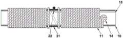
图1为本发明实施例的射频闭合导管产品示意图;1 is a schematic diagram of a radiofrequency closed catheter product according to an embodiment of the present invention;
图2为本发明实施例的射频闭合导管发热段的局部示意图;2 is a partial schematic diagram of a heating section of a radiofrequency closed catheter according to an embodiment of the present invention;
图3为本发明实施例的射频闭合导管线圈内套管与主体管连接部位的局部示意图;3 is a partial schematic diagram of the connection part between the inner sleeve of the radio frequency closed catheter coil and the main body tube according to the embodiment of the present invention;
图4为本发明实施例的射频闭合导管测温装置实施方案一的示意图;4 is a schematic diagram of
图5为本发明实施例的射频闭合导管测温装置实施方案二的示意图;5 is a schematic diagram of
图6为本发明实施例的射频闭合导管测温装置实施方案三的示意图;6 is a schematic diagram of
图7为本发明实施例的射频闭合导管测温装置实施方案四的示意图;7 is a schematic diagram of
图8为本发明实施例的射频闭合导管测温装置实施方案五的示意图;8 is a schematic diagram of
图9为本发明实施例的射频闭合导管测温装置实施方案六的示意图。FIG. 9 is a schematic diagram of Embodiment 6 of the radiofrequency closed catheter temperature measurement device according to the embodiment of the present invention.
具体实施方式Detailed ways
本发明提供一种射频闭合导管,使用本发明的射频闭合导管,无需更换器械即可以对下肢浅静脉和交通静脉曲张的血管进行热闭合,达到治疗下肢静脉曲张的目的。特别的,本发明的射频闭合导管的结构设置,可以同时用于下肢浅静脉和交通静脉的射频消融治疗,缩短手术时间,降低器械更换的风险。另外,本发明的射频闭合导管的测温结构设置及其制作方法,可以在射频消融治疗时实时监测血管的接触温度,使测温结果更直观准确,手术更加安全。The invention provides a radio frequency closure catheter. Using the radio frequency closure catheter of the invention, the superficial veins of the lower extremity and the blood vessels of communicating varicose veins can be thermally closed without changing instruments, so as to achieve the purpose of treating the varicose veins of the lower extremities. In particular, the structure of the radiofrequency closed catheter of the present invention can be used for radiofrequency ablation of the superficial veins and communicating veins of the lower extremity at the same time, thereby shortening the operation time and reducing the risk of instrument replacement. In addition, the temperature measurement structure setting of the radiofrequency closed catheter and the manufacturing method thereof of the present invention can monitor the contact temperature of blood vessels in real time during radiofrequency ablation treatment, so that the temperature measurement results are more intuitive and accurate, and the operation is safer.
本发明的射频闭合导管,主要包括:The radio frequency closed catheter of the present invention mainly includes:
从远端至近端顺序连接的管身、手柄装置、连接线缆和连接器,管身从远端开始设有顺序连接的胶头、发热段和主体管,发热段表面设有用于绝缘和光滑作用的绝缘外套管,内部设有用于加热的、由合金丝绕制而成的线圈,线圈的延长线经过主体管的内腔延伸至手柄装置,进而通过连接线缆延伸至连接器,连接器连接外部设备以提供射频电流。The tube body, the handle device, the connecting cable and the connector are sequentially connected from the distal end to the proximal end. A smooth insulating outer sleeve is provided with a coil made of alloy wire for heating inside. The extension line of the coil extends through the inner cavity of the main tube to the handle device, and then extends to the connector through the connecting cable. connector to connect external devices to supply RF current.
具体地,本发明所述的绝缘外套管可以为单腔管,能够高温热收缩紧贴在线圈的表面,制造材料为FEP、PTFE、PET中的一种,厚度为0.01-0.2mm。Specifically, the insulating outer sleeve of the present invention can be a single-lumen tube, which can be thermally shrunk at high temperature and tightly adhered to the surface of the coil.
具体地,本发明所述的发热段还可以包含线圈内套管,由合金丝绕制而成的线圈缠绕在该线圈内套管上;线圈内套管上开有至少2个小孔,用于线圈延长线穿过并进入线圈内套管内腔;线圈内套管为单腔管,制造材料为PEEK(聚醚醚酮)或P I(聚酰亚胺)的一种。Specifically, the heating section of the present invention may also include a coil inner sleeve, on which a coil made of alloy wire is wound; The coil extension wire passes through and enters the inner cavity of the coil inner sleeve; the coil inner sleeve is a single-lumen tube, and the manufacturing material is one of PEEK (polyetheretherketone) or PI (polyimide).
特别地,本发明所述的线圈内套管表面缠绕有至少两段合金丝分别绕制而成的线圈,形成远端线圈和近端线圈,远端线圈宽度为0.3-4.0cm,近端线圈宽度为4.0-8.0cm,远端线圈和近端线圈之间的间距为0-2.0mm。In particular, the surface of the inner sleeve of the coil of the present invention is wound with at least two coils of alloy wires respectively wound to form a distal coil and a proximal coil, the width of the distal coil is 0.3-4.0 cm, and the proximal coil is 0.3-4.0 cm wide. The width is 4.0-8.0 cm, and the spacing between the distal and proximal coils is 0-2.0 mm.
具体地,本发明所述的每个线圈可以是由一根合金丝在中间位置对折之后,以对折点为起点,在线圈内套管上绕制而成。Specifically, each coil described in the present invention may be formed by winding an alloy wire on the inner casing of the coil after folded in half at the middle position, starting from the folded point.
本发明所述的合金丝用于射频发热,具体地,合金丝材料为52合金(A l l oy52),合金丝表面有P I(聚酰亚胺)绝缘涂层,合金丝的外径为0.1-0.2mm。The alloy wire of the present invention is used for radio frequency heating, specifically, the alloy wire material is 52 alloy (Alloy 52), the surface of the alloy wire is provided with a PI (polyimide) insulating coating, and the outer diameter of the alloy wire is 0.1- 0.2mm.
本发明所述的由合金丝绕制而成的线圈,合金丝之间的间隙设计为0-0.15mm。In the coil wound by the alloy wire according to the present invention, the gap between the alloy wires is designed to be 0-0.15mm.
具体地优选,本发明所述的由合金丝绕制而成的线圈,每段线圈正中间位置留有0.5-3.0mm的未缠绕间隔,用于装设测温装置,测温装置优选包括传导和测量血管内壁温度的测温环和温度传感器。由于本发明的射频闭合导管至少包括远端线圈和近端线圈两段线圈,因此,具有至少两个未缠绕间隔,可以设置至少两组测温装置。这样可以实现整个发热段的多点测温,监测治疗段轴向的多点温度,可以得到更准确和更全面的消融过程温度实时反馈,保证手术更高的成功率和安全性。Specifically, preferably, in the coils of the present invention, which are made of alloy wires, there is an unwinding interval of 0.5-3.0 mm in the middle of each coil, which is used to install a temperature measurement device, and the temperature measurement device preferably includes a conductive And a temperature measuring ring and temperature sensor for measuring the temperature of the inner wall of the blood vessel. Since the radio frequency closure catheter of the present invention at least includes two coils of a distal coil and a proximal coil, there are at least two unwinding intervals, and at least two sets of temperature measuring devices can be provided. In this way, multi-point temperature measurement of the entire heating segment can be realized, and the axial multi-point temperature of the treatment segment can be monitored, and more accurate and more comprehensive real-time temperature feedback during the ablation process can be obtained, ensuring a higher success rate and safety of the operation.
更具体地,本发明所述的由合金丝绕制而成的线圈,每段线圈正中间位置的未缠绕间隔包含一个测温环和至少一个温度传感器。More specifically, in the coil made of alloy wire according to the present invention, the unwinding interval at the middle position of each coil includes a temperature measuring ring and at least one temperature sensor.
具体地,本发明所述的测温环形状设计为完整环和“C形”环两种,材料为铂铱合金、铂金、黄金、不锈钢中的一种,内径范围为1.3-2.0mm,外径为1.4-2.1mm,宽度为0.5-2.5mm。Specifically, the shape of the temperature measuring ring described in the present invention is designed as a complete ring and a "C-shaped" ring, the material is one of platinum-iridium alloy, platinum, gold, and stainless steel, the inner diameter is in the range of 1.3-2.0mm, and the outer diameter is 1.3-2.0mm. The diameter is 1.4-2.1mm, and the width is 0.5-2.5mm.
优选地,本发明所述的温度传感器装置于每段线圈的未缠绕间隔,但温度传感器的测温头端不与合金丝直接接触。通过温度传感器头端与发热线圈的合金丝隔离,可以实现更多的组织温度测量,使得测温反馈更直接,射频闭合更安全。Preferably, the temperature sensor device of the present invention is installed in the unwinding interval of each coil, but the temperature measuring head end of the temperature sensor is not in direct contact with the alloy wire. By isolating the head end of the temperature sensor from the alloy wire of the heating coil, more tissue temperature measurements can be achieved, making the temperature measurement feedback more direct and the radio frequency closure safer.
具体地,本发明所述的胶头为环氧树脂胶水或UV胶水固化形成的圆形胶头。Specifically, the glue head of the present invention is a circular glue head formed by curing epoxy resin glue or UV glue.
优选地,本发明所述的主体管为多层单腔编织管,外层材料使用Pebax7233或PA12,中间层为304不锈钢丝网状编织,内层材料为Pebax或PA12,其中PA12材料的邵氏硬度为77D。本发明优选主体管采用多层编织网管,实现了导管管身柔韧性、软硬度和推送性俱佳,管身可以大角度弯折而不损坏,使得本发明的导管能够更好的通过迂曲的血管,适用更复杂的病变部位。Preferably, the main body tube of the present invention is a multi-layer single-lumen braided tube, the outer layer material is Pebax7233 or PA12, the middle layer is 304 stainless steel wire mesh braid, and the inner layer material is Pebax or PA12, wherein the Shore of the PA12 material is The hardness is 77D. In the present invention, the main body tube preferably adopts a multi-layer braided mesh tube, so that the flexibility, hardness and pushability of the tube body of the catheter are all good, and the tube body can be bent at a large angle without being damaged, so that the catheter of the present invention can better pass through the tortuosity blood vessels, suitable for more complex lesions.
具体地,本发明所述线圈内套管近端5mm-15mm部分内嵌进入主体管远端内腔,采用焊接或环氧树脂胶水粘接固定,实现了发热段与主体管的连接。Specifically, the 5mm-15mm portion of the proximal end of the coil inner sleeve of the present invention is embedded into the inner cavity of the distal end of the main body tube, and is fixed by welding or epoxy glue to realize the connection between the heating section and the main body tube.
下面将结合附图对本发明的技术方案进行清楚、完整地描述,显然,所描述的实施例是本发明一部分实施例,而不是全部的实施例。基于本发明中的实施例,本领域普通技术人员在没有做出创造性劳动前提下所获得的所有其他实施例,都属于本发明保护的范围。The technical solutions of the present invention will be clearly and completely described below with reference to the accompanying drawings. Obviously, the described embodiments are a part of the embodiments of the present invention, but not all of the embodiments. Based on the embodiments of the present invention, all other embodiments obtained by those of ordinary skill in the art without creative efforts shall fall within the protection scope of the present invention.
在本发明的描述中,需要说明的是,术语“中心”、“上”、“下”、“左”、“右”、“竖直”、“水平”、“内”、“外”等指示的方位或位置关系为基于附图所示的方位或位置关系,仅是为了便于描述本发明和简化描述,而不是指示或暗示所指的装置或元件必须具有特定的方位、以特定的方位构造和操作,因此不能理解为对本发明的限制。此外,术语“第一”、“第二”、“第三”仅用于描述目的,而不能理解为指示或暗示相对重要性。In the description of the present invention, it should be noted that the terms "center", "upper", "lower", "left", "right", "vertical", "horizontal", "inner", "outer", etc. The indicated orientation or positional relationship is based on the orientation or positional relationship shown in the accompanying drawings, which is only for the convenience of describing the present invention and simplifying the description, rather than indicating or implying that the indicated device or element must have a specific orientation or a specific orientation. construction and operation, and therefore should not be construed as limiting the invention. Furthermore, the terms "first", "second", and "third" are used for descriptive purposes only and should not be construed to indicate or imply relative importance.
在本发明的描述中,需要说明的是,除非另有明确的规定和限定,术语“安装”、“相连”、“连接”应做广义理解,例如,可以是固定连接,也可以是可拆卸连接,或一体地连接;可以是机械连接,也可以是电连接;可以是直接相连,也可以通过中间媒介间接相连,可以是两个元件内部的连通。对于本领域的普通技术人员而言,可以具体情况理解上述术语在本发明中的具体含义。In the description of the present invention, it should be noted that the terms "installed", "connected" and "connected" should be understood in a broad sense, unless otherwise expressly specified and limited, for example, it may be a fixed connection or a detachable connection Connection, or integral connection; can be mechanical connection, can also be electrical connection; can be directly connected, can also be indirectly connected through an intermediate medium, can be internal communication between two elements. For those of ordinary skill in the art, the specific meanings of the above terms in the present invention can be understood in specific situations.
实施例1Example 1
请参见图1所示,本实施例的射频闭合导管,从远端到近端顺序设置有胶头1、发热段2、主体管3、应力释放管5、手柄6、导丝口7、连接线缆8和连接器9,其中胶头1、发热段2、主体管3由远端向近端依次设置,组成管身4。应力释放管5套设在主体管3的近端,手柄6的远端出口与主体管3的近端固定连接,并且手柄6的远端出口还与应力释放管5的近端固定连接。导丝口7位于手柄6的近端。连接线缆8的一端在手柄6处与发热段2电性连接,另一端与连接器9电性连接。连接器9用于连接外部设备以提供射频电流。Referring to FIG. 1 , the radio frequency closure catheter of this embodiment is sequentially provided with a
请参见图2所示,发热段2包括线圈内套管10、由合金丝11缠绕而成的两段线圈、绝缘外套管12;其中,Referring to FIG. 2, the
线圈内套管10为单腔管,其表面设置有两段各由一根合金丝11对折之后缠绕而成的线圈,在本实施例中优选设计的两段线圈,分别为图2中显示为较窄的远端线圈和较宽的近端线圈;其中,远端线圈宽度为0.3-4.0cm,近端线圈宽度为4.0-8.0cm,缠绕远端线圈所用的合金丝11长度为30-120cm,缠绕近端线圈所用的合金丝11的长度为120-260cm;远端线圈的缠绕起点距离线圈内套管10的远端开口1-10mm,近端线圈的缠绕起点与远端线圈的缠绕终点距离为0-2mm;在每段线圈的缠绕过程中,所有合金丝11之间需要留有0-0.15mm的间隙;并且,The
远端线圈和近端线圈上各自应留有一段宽度为0.5-3.0mm的未缠绕间隔,本发明优选该未缠绕间隔位于每段线圈的中间位置;并且具体地,在每段线圈的未缠绕间隔的表面,合金丝11的走向沿该射频闭合导管的轴向;并且,Each of the distal coil and the proximal coil should have an unwinding interval with a width of 0.5-3.0 mm, and the present invention preferably the unwinding interval is located in the middle of each coil; and specifically, in the unwinding of each coil spaced surfaces, the direction of the
合金丝11绕制而成的远端线圈或近端线圈与线圈内套管10之间采用胶水粘接固定。The distal coil or proximal coil formed by winding the
在本实施例中,线圈内套管10的材质优选为耐高温的聚醚醚酮(PEEK)或聚酰亚胺(PI)材料,具体地例如使用聚醚醚酮(PEEK);线圈内套管10的长度为5.0-15.0mm,优选9.0-11.0mm,线圈内套管10的内径为1.0-1.7mm,外径为1.2-1.9mm,优选内径1.10-1.20mm,优选外径1.30-1.40mm。In this embodiment, the material of the
在线圈内套管10表面的线圈缠绕终点位置分别开小孔,称之为圆形穿线孔14和15,将两段线圈合金丝11的延长线分别通过圆形穿线孔14和15穿入线圈内套管10的内腔,如图2所示。Small holes are respectively opened at the end positions of the coil winding on the surface of the
在图2所示的实施例中,绝缘外套管12为单腔管,能够高温热收缩紧贴在由合金丝11绕制而成的线圈的表面,制造材料可选自FEP、PTFE、PET中的一种,厚度为0.01-0.2mm。In the embodiment shown in FIG. 2 , the insulating
此外,请结合图1和图2所示,射频闭合导管的内部还穿设有导丝管13,导丝管的一端从线圈内套管10的远端开口穿入,经过主体管3的内腔、手柄6的内腔,另一端插入导丝口7的远端内腔,与导丝口7相互连接并连通。In addition, as shown in FIG. 1 and FIG. 2 , a
如图3所示,其展示了线圈内套管10与主体管3的连接部分。具体地,在线圈内套管10的近端管口,将合金丝11的延长线分别剪去不同长度,所有合金丝11应至少露出线圈内套管10的近端管口0.5mm,所有合金丝11的近端头端使用锡焊分别连接一根长度为100cm的铜导线16。As shown in FIG. 3 , it shows the connection part of the coil
具体地,合金丝11的材料为表面具有PI(聚酰亚胺)绝缘涂层的52合金(镍铁合金),合金丝11的外径为0.1-0.2mm。铜导线16的材料为表面具有PI(聚酰亚胺)或PA(尼龙)绝缘涂层的铜线,铜导线16的外径为0.1-0.15mm。同时,线圈内套管10上的圆形穿线孔14和15的内径为0.35-0.5mm。Specifically, the material of the
线圈内套管10上由合金丝11绕制而成的远端线圈和近端线圈中间的未缠绕间隔上可设置测温装置。测温装置的具体结构和制作方法将在下述的实施方式中详细说明。A temperature measuring device can be arranged on the unwinding space between the distal coil and the proximal coil wound by the
测温装置实施方式一
请参见图4,在本实施方式中,每组测温装置包括一个测温环17和一个温度传感器18。测温环17外形为“C形”环。Referring to FIG. 4 , in this embodiment, each set of temperature measuring devices includes a
如图4所示,在本实施例中,测温环17装配于线圈的未缠绕间隔的中间位置;测温环17的两侧边缘不与线圈的合金丝11接触;测温环17的横截开口位于合金丝11沿该射频闭合导管轴向设置的直段部分的两侧,且不与合金丝11接触;测温环17使用胶水固定在线圈内套管10的表面,胶水优选为UV胶水或乐泰4011胶水。As shown in FIG. 4 , in this embodiment, the
继续参见图4,在线圈内套管10的表面,测温环17与合金丝11的近端一侧的间隙位置开一圆形穿线孔19,孔径尺寸为0.15-0.3mm,将温度传感器18的延长线从圆形穿线孔19穿入线圈内套管10的内腔,该延长线后续经过主体管3的内腔、手柄6、连接线缆8连接到连接器9(请结合参见图1);温度传感器18的头端设置在测温环17的表面中心位置,使用UV胶水或乐泰4011胶水粘接固定。Continue to refer to FIG. 4 , on the surface of the
在本实施例中,其余线圈段的测温装置的设置方式与上述示例一致。In this embodiment, the temperature measuring devices of the remaining coil segments are set in the same manner as in the above example.
测温装置实施方式二The second embodiment of the temperature measuring device
请参见图5,在本实施方式中,每组测温装置包括一个测温环21和一个温度传感器18。测温环21外形为圆环状(即完整环)。Referring to FIG. 5 , in this embodiment, each set of temperature measuring devices includes a temperature measuring ring 21 and a
如图5所示,在本实施方式中,在线圈内套管10的表面,线圈的未缠绕间隔的中间位置开一圆形穿线孔20,孔径尺寸为0.15-0.3mm;将温度传感器18的延长线从穿线孔20穿入线圈内套管10的内腔,该延长线后续经过主体管3的内腔、手柄6、连接线缆8连接到连接器9(请结合参见图1);温度传感器18的头端设置在线圈的未缠绕间隔的中间位置,并与圆形穿线孔20保持0.5-1.5mm的距离,使用UV胶水或乐泰4011胶水粘接固定温度传感器18的头端。As shown in FIG. 5 , in this embodiment, on the surface of the
继续参见图5,测温环21装配于线圈的未缠绕间隔的中间位置,测温环21应完全覆盖住温度传感器18,并且测温环21的两侧边缘不与线圈的合金丝11接触,使用环氧乙烷胶水、UV胶水或乐泰4011胶水固定测温环21,具体地,线圈内套管10和测温环21之间的缝隙使用胶水填封以固定测温环21。Continue to refer to FIG. 5, the temperature measuring ring 21 is assembled in the middle of the unwinding interval of the coil, the temperature measuring ring 21 should completely cover the
在本实施例中,其余线圈段的测温装置的设置与上述示例一致。In this embodiment, the settings of the temperature measuring devices of the remaining coil segments are consistent with the above examples.
测温装置实施方式三The third embodiment of the temperature measuring device
请参见图6,在本实施方式中,每组测温装置包括一个测温环31和一个温度传感器18。测温环31外形为圆环状(即完整环)。Referring to FIG. 6 , in this embodiment, each set of temperature measuring devices includes a
如图6所示,在线圈内套管10的表面预先确定好线圈的位置,并且在线圈预定的未缠绕间隔处的中间位置,在线圈内套管10的表面使用胶水固定测温环31,在测温环31的中间位置开一圆形穿线孔22,该圆形穿线孔22测温环31之内的线圈内套管10,将温度传感器18的延长线通过圆形穿线孔22穿入线圈内套管10的内腔,该延长线后续经过主体管3的内腔、手柄6、连接线缆8连接到连接器9(请结合参见图1);温度传感器18的头端装设在测温环31的表面中间位置,并与圆形穿线孔22保持0.5-1.5mm的距离,同时使用胶水粘接固定温度传感器18的头端。As shown in FIG. 6 , the position of the coil is predetermined on the surface of the
之后,在线圈内套管10的表面按照预先确定好的线圈位置从远端开始缠绕合金丝11,直至缠绕到测温环31的远端一侧,合金丝11应缠绕覆盖住测温环31远端0.1-0.3mm,使用胶水固定已缠绕的合金丝11;在测温环31表面距离近端边缘的0.1-0.3mm位置继续缠绕合金丝11,直至完成该段线圈需要的缠绕宽度,合金丝11的延长线通过穿线孔14穿入线圈内套管10的内腔。After that, the
在本实施方式中,胶水可以为环氧乙烷胶水、UV胶水或乐泰4011胶水,优选乐泰4011胶水。In this embodiment, the glue may be ethylene oxide glue, UV glue or Loctite 4011 glue, preferably Loctite 4011 glue.
在本实施方式中,其余线圈段的测温装置的设置与上述示例一致。In this embodiment, the settings of the temperature measuring devices of the remaining coil segments are consistent with the above examples.
测温装置实施方式四
请参见图7,在本实施方式中,每组测温装置包括一个测温环41和一个温度传感器18。在本实施方式中,测温环41外形为圆环状。Referring to FIG. 7 , in this embodiment, each set of temperature measuring devices includes a temperature measuring ring 41 and a
如图7所示,本实施方式中,在线圈内套管10的表面,线圈的未缠绕间隔的中间位置开一圆形穿线孔23,孔径尺寸为0.15-0.3mm,将温度传感器18的延长线从圆形穿线孔23穿入线圈内套管10的内腔,该延长线后续经过主体管3的内腔、手柄6、连接线缆8连接到连接器9(请结合参见图1);温度传感器18的头端装设在线圈的未缠绕间隔的中间位置,与圆形穿线孔23保持0.5-1.5mm的距离,并使用胶水粘接固定温度传感器18的头端。As shown in FIG. 7 , in this embodiment, on the surface of the
从线圈外套管10的远端开始穿进测温环41到线圈的未缠绕间隔的中间位置,测温环41应完全覆盖住温度传感器18的头端,并且测温环41的两侧边缘应覆盖0.14-0.75mm宽度的合金丝11;线圈内套管10和测温环41之间的缝隙使用胶水填封固定。From the far end of the
在本实施方式中,胶水为环氧乙烷胶水、UV胶水或乐泰4011胶水。In this embodiment, the glue is ethylene oxide glue, UV glue or Loctite 4011 glue.
在本实施方式中,其余线圈段的测温装置的设置方式与上述示例一致。In this embodiment, the temperature measuring devices of the remaining coil segments are arranged in the same manner as in the above example.
测温装置实施方式五
请参见图8,在本实施方式中,每组测温装置包括一个测温环51和一个温度传感器18。在本实施方式中,测温环51外形为圆环状。Referring to FIG. 8 , in this embodiment, each set of temperature measuring devices includes a
如图8所示,本实施方式中,在线圈内套管10的表面,线圈的未缠绕间隔的中间位置开一圆形穿线孔24,孔径尺寸为0.15-0.3mm;在测温环51的表面中间位置开一圆形穿线孔25,孔径尺寸为0.15-0.3mm。As shown in FIG. 8 , in this embodiment, on the surface of the
从线圈外套管10的远端开始穿进测温环51到线圈的未缠绕间隔的中间位置;将温度传感器18的延长线穿入穿线孔25和穿线孔24进入线圈内套管10的内腔,该延长线后续经过主体管3的内腔、手柄6、连接线缆8连接到连接器9(请结合参见图1);并设置温度传感器18的头端在测温环51的外表面;使用环氧树脂胶水填封线圈内套管10和测温环51之间的缝隙,移动测温环51,使得测温环51的两侧边缘覆盖0.14-0.75mm宽度的合金丝11;温度传感器18的头端设置在测温环51的外表面中间位置,并与穿线孔25保持0.5-1.5mm的距离,使用UV胶水或乐泰4011胶水固定温度传感器18的头端。From the distal end of the coil
在本实施方式中,其余线圈段的测温装置设置方式与上述示例一致。In this embodiment, the temperature measuring devices of the remaining coil segments are set in the same manner as in the above example.
测温装置实施方式六Embodiment 6 of the temperature measuring device
在本实施方式中,测温装置无测温环,仅包括温度传感器18。In this embodiment, the temperature measuring device has no temperature measuring ring, and only includes the
请参见图9所示,本实施方式中,在线圈内套管10的表面,线圈的未缠绕间隔的中间位置开一圆形穿线孔26,孔径尺寸为0.15-0.3mm,将温度传感器18的延长线从穿线孔26穿入线圈内套管10的内腔,该延长线后续经过主体管3的内腔、手柄6、连接线缆8连接到连接器9(请结合参见图1);温度传感器18的头端装设在线圈的未缠绕间隔的中间位置,与圆形穿线孔26在周向保持0.5-1.5mm的距离,并使用UV胶水或乐泰4011胶水固定温度传感器18的头端。Referring to FIG. 9 , in this embodiment, on the surface of the
在本实施方式中,其余线圈段的测温装置与上述示例一致。In this embodiment, the temperature measuring devices of the remaining coil segments are the same as the above examples.
在本发明的射频闭合导管的不同实施例中,不同线圈段的测温装置的设置可以采用上述六种实施方式中任一,并不限定为只能采用相同的设置方式。In different embodiments of the radiofrequency closed catheter of the present invention, the temperature measuring devices of different coil segments can be arranged in any of the above six embodiments, and are not limited to only the same arrangement.
在本实施例中,测温环的材料可选自铂铱合金、铂金、黄金、不锈钢中的一种,测温环的内径范围为1.3-2.0mm,外径范围为1.4-2.1mm,宽度范围为0.5-2.5mm。In this embodiment, the material of the temperature measuring ring can be selected from platinum-iridium alloy, platinum, gold, and stainless steel. The inner diameter of the temperature measuring ring is 1.3-2.0mm, the outer diameter is 1.4-2.1mm, and the width The range is 0.5-2.5mm.
在本实施例中,温度传感器18为热电偶,类型为K型,延长线的截面尺寸为0.12*0.24mm,长度为100cm。In this embodiment, the
如图2所示,在线圈缠绕完成并且测温装置设置完成后,在整个发热段2最外层套上绝缘外套管12,保持绝缘外套管12的远端与线圈内套管10的远端开口平齐,并使用热收缩机热缩绝缘外套管12以完全包裹发热段2,热缩温度为200-260℃。具体地,绝缘外套管12的材料可以为FEP(氟乙烯丙烯共聚物),颜色透明,壁厚为0.09-0.11mm,长度为10-15mm,扩大内径>1.9mm,恢复内径<1.3mm。As shown in FIG. 2 , after the coil winding is completed and the temperature measuring device is set, the outermost layer of the
在本实施例中,导丝管13形状为单腔管状。导丝管13在安装时,将导丝管13的一端从线圈内套管10的远端开口穿入,依次穿入线圈内套管10、主体管3和手柄6的内腔,并且导丝管13的远端暴露出线圈内套管10的远端开口1.0-5.0mm,优选为2.0-3.0mm,导丝管13的近端插入导丝口7的远端内腔,插入长度为0.3-1.0cm,并使用环氧树脂胶水或UV胶水将接口粘接固定。具体地,导丝管13的材料可以为PI(聚酰亚胺),内径为0.5-0.7mm,外径为0.6-0.8mm。In this embodiment, the
如图2所示,胶头1位于射频闭合导管的最远端,作用是使导管头端更圆滑,以保证手术使用中导管的移动不会损伤血管。胶头1的材料使用环氧树脂胶水或UV胶水,具体地,将环氧树脂胶水或UV胶水一层层涂抹在导丝管13的外表面并固化以形成胶头1,胶头1的形状应基本为球形,外径为1.5-2.33mm,优选为1.7-2.1mm。As shown in Figure 2, the
请参考图3,将所有铜导线16和温度传感器18的延长线穿入主体管3的内腔,线圈内套管10的近端5-10mm长度表面涂上环氧树脂胶水,将线圈内套管10涂胶水的部分内嵌入主体管3的内腔以粘接线圈内套管10和主体管3。主体管3为多层单腔编织管,外层材料使用Pebax7233或PA12,中间层为304不锈钢丝网状编织,内层材料为Pebax7233或PA12,使用的PA12材料的邵氏硬度为77D,主体管的内径为1.20-1.80mm,外径为1.65-2.25mm。Please refer to Fig. 3, insert all the
请参考图1,在主体管3的近端套上应力释放管5,主体管3近端开口有合金丝11和温度传感器18的延长线,使用锡焊将所有合金丝11和温度传感器18的延长线焊接在手柄6内部的电路板上,将连接线缆8的一端同样使用锡焊焊接到电路板上,连接线缆8的另一端使用锡焊焊接到连接器9,使用乐泰4011胶水粘接固定主体管3的近端到手柄6的远端出口,同时使用乐泰4011胶水粘接固定应力释放管5的近端和手柄6的远端出口。Referring to FIG. 1 , a
具体地例如,应力释放管5的材料为硅橡胶,形状为带有空腔的圆柱体,长度为3-10cm;手柄6的材料为PC+ABS树脂,采用注塑加工工艺制成,形状可以为常规介入器械手柄形状;连接器9为标准件,例如可以采用雷莫(上海)贸易有限公司的REDEL12针塑料连接器。Specifically, for example, the material of the
本发明具有以下优点:The present invention has the following advantages:
1、本发明的射频闭合导管,通过设置远端线圈和近端线圈并优选选择这两种线圈为不同的宽度设计,可以在无需更换器械的情况下实现下肢浅静脉曲张和交通静脉曲张两种病变部位的射频消融,其中短宽度的远端线圈单独作用于交通静脉曲张的治疗,远端线圈和近端线圈联合用于下肢浅静脉曲张的治疗;1. The radio frequency closure catheter of the present invention, by setting the distal coil and the proximal coil and preferably selecting these two coils to be designed with different widths, can realize two types of superficial lower extremity varicose veins and communicating varicose veins without changing instruments. Radiofrequency ablation of lesions, in which the short-width distal coil is used alone for the treatment of communicating varicose veins, and the distal coil and proximal coil are combined for the treatment of superficial lower extremity varicose veins;
2、本发明的射频闭合导管及相应的制作方法,通过设置温度传感器头端与用于发热的线圈的合金丝隔离,可以实现更多的组织温度测量,使得测温反馈更直接,射频消融更安全;2. The radio frequency closed catheter and the corresponding manufacturing method of the present invention can achieve more tissue temperature measurement by setting the temperature sensor head end to be isolated from the alloy wire used for the heating coil, so that the temperature measurement feedback is more direct, and the radio frequency ablation is more convenient. Safety;
3、本发明的射频闭合导管及相应的制作方法,在至少一段线圈的中间部位设置测温装置,更优选地是在每段线圈中间部位均设置测温装置,具体可以包括测温环和温度传感器,由于本发明的射频闭合导管包括多段线圈,在每段线圈的中间部位设置测温装置,则在整个射频闭合导管的发热段设置了多组测温装置,进而可以实现整个发热段的多点测温,监测治疗段轴向的多点温度,可以得到更准确和更全面的消融过程实时反馈,保证手术更高的成功率和安全性;3. In the radio frequency closed catheter and the corresponding manufacturing method of the present invention, a temperature measuring device is arranged in the middle part of at least one section of the coil, more preferably, a temperature measuring device is arranged in the middle part of each section of the coil, which may specifically include a temperature measuring ring and a temperature measuring device. The sensor, because the radio frequency closed catheter of the present invention includes multiple coils, and a temperature measuring device is arranged in the middle of each coil, then multiple sets of temperature measuring devices are set in the heating section of the entire radio frequency closed catheter. Point temperature measurement, monitoring the multi-point temperature in the axial direction of the treatment section, can get more accurate and more comprehensive real-time feedback of the ablation process, and ensure a higher success rate and safety of the operation;
4、本发明的射频闭合导管,其主体管采用多层编织网管,实现了该射频闭合导管管身柔韧性、软硬度和推送性俱佳,管身可以大角度弯折而不损坏,使得本发明的导管能够更好的通过迂曲的血管,适用更复杂的病变部位。4. The main body of the radio frequency closure catheter of the present invention adopts a multi-layer braided mesh tube, which realizes that the radio frequency closure catheter body has excellent flexibility, hardness and pushability, and the tube body can be bent at a large angle without damage, so that the The catheter of the present invention can better pass through tortuous blood vessels, and is suitable for more complicated lesions.
最后应说明的是:以上实施例及实施方式仅用以说明本发明的技术方案,而非对其限制;尽管参照前述各实施例及实施方式对本发明进行了详细的说明,本领域的普通技术人员应当理解:其依然可以对前述各实施例及实施方式所记载的技术方案进行修改,或者对其中部分或者全部技术特征进行等同替换;而这些修改或者替换,并不使相应技术方案的本质脱离本发明各实施例及实施方式技术方案的范围。本发明仅受权利要求书及其全部范围和等效物的限制。Finally, it should be noted that the above examples and implementations are only used to illustrate the technical solutions of the present invention, but not to limit them; Personnel should understand that it is still possible to modify the technical solutions recorded in the foregoing embodiments and implementations, or to perform equivalent replacements on some or all of the technical features; and these modifications or replacements do not make the essence of the corresponding technical solutions depart from The scope of the technical solutions of the embodiments and implementations of the present invention. The present invention is to be limited only by the claims and their full scope and equivalents.
Claims (20)
Translated fromChinesePriority Applications (2)
| Application Number | Priority Date | Filing Date | Title |
|---|---|---|---|
| CN202111200587.7ACN113729926B (en) | 2019-12-27 | 2019-12-27 | Radio frequency closure catheter and manufacturing method thereof |
| CN201911375916.4ACN111067617A (en) | 2019-12-27 | 2019-12-27 | Radiofrequency closed catheter and method of making the same |
Applications Claiming Priority (1)
| Application Number | Priority Date | Filing Date | Title |
|---|---|---|---|
| CN201911375916.4ACN111067617A (en) | 2019-12-27 | 2019-12-27 | Radiofrequency closed catheter and method of making the same |
Related Child Applications (1)
| Application Number | Title | Priority Date | Filing Date |
|---|---|---|---|
| CN202111200587.7ADivisionCN113729926B (en) | 2019-12-27 | 2019-12-27 | Radio frequency closure catheter and manufacturing method thereof |
Publications (1)
| Publication Number | Publication Date |
|---|---|
| CN111067617Atrue CN111067617A (en) | 2020-04-28 |
Family
ID=70318471
Family Applications (2)
| Application Number | Title | Priority Date | Filing Date |
|---|---|---|---|
| CN201911375916.4APendingCN111067617A (en) | 2019-12-27 | 2019-12-27 | Radiofrequency closed catheter and method of making the same |
| CN202111200587.7AActiveCN113729926B (en) | 2019-12-27 | 2019-12-27 | Radio frequency closure catheter and manufacturing method thereof |
Family Applications After (1)
| Application Number | Title | Priority Date | Filing Date |
|---|---|---|---|
| CN202111200587.7AActiveCN113729926B (en) | 2019-12-27 | 2019-12-27 | Radio frequency closure catheter and manufacturing method thereof |
Country Status (1)
| Country | Link |
|---|---|
| CN (2) | CN111067617A (en) |
Cited By (10)
| Publication number | Priority date | Publication date | Assignee | Title |
|---|---|---|---|---|
| CN112294430A (en)* | 2020-09-17 | 2021-02-02 | 杭州堃博生物科技有限公司 | Radiofrequency ablation catheter and production process thereof |
| CN112957119A (en)* | 2021-01-29 | 2021-06-15 | 丁兆霖 | Multi-joint functional negative plate connecting wire |
| CN114010305A (en)* | 2021-11-17 | 2022-02-08 | 上海玮琅医疗科技有限公司 | Radio frequency ablation catheter and system |
| CN115381548A (en)* | 2022-08-01 | 2022-11-25 | 上海玮琅医疗科技有限公司 | Radio frequency ablation catheter capable of locking connection tail wire |
| CN115381549A (en)* | 2022-08-01 | 2022-11-25 | 上海玮琅医疗科技有限公司 | A microcatheter for radiofrequency ablation with adjustable curvature |
| CN116570363A (en)* | 2023-07-14 | 2023-08-11 | 北京先瑞达医疗科技有限公司 | A radio frequency catheter |
| CN116570362A (en)* | 2023-07-14 | 2023-08-11 | 北京先瑞达医疗科技有限公司 | Radio frequency catheter control system and method |
| CN118948422A (en)* | 2024-08-29 | 2024-11-15 | 邦士医疗科技股份有限公司 | A venous cavity closure device |
| CN118975846A (en)* | 2024-08-29 | 2024-11-19 | 邦士医疗科技股份有限公司 | A venous cavity closure device |
| CN119423956A (en)* | 2024-08-29 | 2025-02-14 | 邦士医疗科技股份有限公司 | A venous cavity closure device |
Citations (16)
| Publication number | Priority date | Publication date | Assignee | Title |
|---|---|---|---|---|
| US5797905A (en)* | 1994-08-08 | 1998-08-25 | E. P. Technologies Inc. | Flexible tissue ablation elements for making long lesions |
| EP0886487B1 (en)* | 1996-03-11 | 2003-12-10 | Medtronic, Inc. | Apparatus for r-f ablation |
| CN1549694A (en)* | 2001-05-01 | 2004-11-24 | �����ɷ� | spiral electrophysiology catheter |
| CN101355912A (en)* | 2005-07-21 | 2009-01-28 | Vnus医疗技术公司 | Systems and methods for treating hollow anatomical structures |
| CN102860867A (en)* | 2012-10-15 | 2013-01-09 | 陈平根 | Multi-electrode radio frequency ablation catheter and design method thereof |
| CN104510529A (en)* | 2013-09-29 | 2015-04-15 | 柯惠有限合伙公司 | Medical treatment device adjustable in length and/or diameter |
| CN104684499A (en)* | 2012-08-17 | 2015-06-03 | 麦德托尼克消融前沿有限公司 | Electrophysiology Catheter Design |
| CN105078571A (en)* | 2015-05-13 | 2015-11-25 | 上海魅丽纬叶医疗科技有限公司 | Corrugated type radiofrequency ablation guide tube with wall-adherent adjusting wire and equipment thereof |
| CN105167840A (en)* | 2014-06-20 | 2015-12-23 | 上海安通医疗科技有限公司 | Multi-electrode renal artery radiofrequency ablation catheter |
| CN105228694A (en)* | 2013-03-12 | 2016-01-06 | 波士顿科学国际有限公司 | For regulating neural medical system and method |
| CN105326562A (en)* | 2014-06-24 | 2016-02-17 | 上海安通医疗科技有限公司 | Catheter device for regulating renal nerves |
| CN105361943A (en)* | 2014-08-27 | 2016-03-02 | 上海安通医疗科技有限公司 | Catheter device for adjusting nerves |
| CN105377168A (en)* | 2013-05-08 | 2016-03-02 | 波士顿科学国际有限公司 | Systems and methods for temperature monitoring and control during an ablation procedure |
| CN106999059A (en)* | 2015-01-15 | 2017-08-01 | 日本来富恩株式会社 | Conduit |
| CN107349010A (en)* | 2017-07-07 | 2017-11-17 | 昆山雷盛医疗科技有限公司 | Radio frequency ablation probe and preparation method thereof |
| CN108420528A (en)* | 2017-02-15 | 2018-08-21 | 韦伯斯特生物官能(以色列)有限公司 | Electrophysiological instrument constructs |
Family Cites Families (5)
| Publication number | Priority date | Publication date | Assignee | Title |
|---|---|---|---|---|
| DK3122414T3 (en)* | 2014-03-26 | 2021-05-31 | Venclose Inc | Cable unit |
| CN106308922A (en)* | 2015-06-30 | 2017-01-11 | 四川锦江电子科技有限公司 | Multi-electrode ablation device |
| US10363090B2 (en)* | 2016-01-05 | 2019-07-30 | Biosense Webster (Israel) Ltd. | Catheter with flow diverter and force sensor |
| KR101963621B1 (en)* | 2016-11-04 | 2019-04-01 | 주식회사 스타메드 | Radiofrequency ablation device |
| CN107997818A (en)* | 2017-11-10 | 2018-05-08 | 上海导向医疗系统有限公司 | The cryoablation pin of rewarming and thermotherapeutic function is realized by electric heating wire |
- 2019
- 2019-12-27CNCN201911375916.4Apatent/CN111067617A/enactivePending
- 2019-12-27CNCN202111200587.7Apatent/CN113729926B/enactiveActive
Patent Citations (16)
| Publication number | Priority date | Publication date | Assignee | Title |
|---|---|---|---|---|
| US5797905A (en)* | 1994-08-08 | 1998-08-25 | E. P. Technologies Inc. | Flexible tissue ablation elements for making long lesions |
| EP0886487B1 (en)* | 1996-03-11 | 2003-12-10 | Medtronic, Inc. | Apparatus for r-f ablation |
| CN1549694A (en)* | 2001-05-01 | 2004-11-24 | �����ɷ� | spiral electrophysiology catheter |
| CN101355912A (en)* | 2005-07-21 | 2009-01-28 | Vnus医疗技术公司 | Systems and methods for treating hollow anatomical structures |
| CN104684499A (en)* | 2012-08-17 | 2015-06-03 | 麦德托尼克消融前沿有限公司 | Electrophysiology Catheter Design |
| CN102860867A (en)* | 2012-10-15 | 2013-01-09 | 陈平根 | Multi-electrode radio frequency ablation catheter and design method thereof |
| CN105228694A (en)* | 2013-03-12 | 2016-01-06 | 波士顿科学国际有限公司 | For regulating neural medical system and method |
| CN105377168A (en)* | 2013-05-08 | 2016-03-02 | 波士顿科学国际有限公司 | Systems and methods for temperature monitoring and control during an ablation procedure |
| CN104510529A (en)* | 2013-09-29 | 2015-04-15 | 柯惠有限合伙公司 | Medical treatment device adjustable in length and/or diameter |
| CN105167840A (en)* | 2014-06-20 | 2015-12-23 | 上海安通医疗科技有限公司 | Multi-electrode renal artery radiofrequency ablation catheter |
| CN105326562A (en)* | 2014-06-24 | 2016-02-17 | 上海安通医疗科技有限公司 | Catheter device for regulating renal nerves |
| CN105361943A (en)* | 2014-08-27 | 2016-03-02 | 上海安通医疗科技有限公司 | Catheter device for adjusting nerves |
| CN106999059A (en)* | 2015-01-15 | 2017-08-01 | 日本来富恩株式会社 | Conduit |
| CN105078571A (en)* | 2015-05-13 | 2015-11-25 | 上海魅丽纬叶医疗科技有限公司 | Corrugated type radiofrequency ablation guide tube with wall-adherent adjusting wire and equipment thereof |
| CN108420528A (en)* | 2017-02-15 | 2018-08-21 | 韦伯斯特生物官能(以色列)有限公司 | Electrophysiological instrument constructs |
| CN107349010A (en)* | 2017-07-07 | 2017-11-17 | 昆山雷盛医疗科技有限公司 | Radio frequency ablation probe and preparation method thereof |
Cited By (16)
| Publication number | Priority date | Publication date | Assignee | Title |
|---|---|---|---|---|
| CN112294430A (en)* | 2020-09-17 | 2021-02-02 | 杭州堃博生物科技有限公司 | Radiofrequency ablation catheter and production process thereof |
| CN112957119A (en)* | 2021-01-29 | 2021-06-15 | 丁兆霖 | Multi-joint functional negative plate connecting wire |
| CN114010305B (en)* | 2021-11-17 | 2022-12-02 | 上海玮琅医疗科技有限公司 | Radio frequency ablation catheter and system |
| CN114010305A (en)* | 2021-11-17 | 2022-02-08 | 上海玮琅医疗科技有限公司 | Radio frequency ablation catheter and system |
| CN115381548B (en)* | 2022-08-01 | 2023-09-19 | 上海玮琅医疗科技有限公司 | Radio frequency ablation catheter capable of locking connection tail wire |
| CN115381549A (en)* | 2022-08-01 | 2022-11-25 | 上海玮琅医疗科技有限公司 | A microcatheter for radiofrequency ablation with adjustable curvature |
| CN115381548A (en)* | 2022-08-01 | 2022-11-25 | 上海玮琅医疗科技有限公司 | Radio frequency ablation catheter capable of locking connection tail wire |
| CN115381549B (en)* | 2022-08-01 | 2024-12-17 | 上海玮琅医疗科技有限公司 | Radio frequency ablation microcatheter with adjustable camber |
| CN116570363A (en)* | 2023-07-14 | 2023-08-11 | 北京先瑞达医疗科技有限公司 | A radio frequency catheter |
| CN116570362A (en)* | 2023-07-14 | 2023-08-11 | 北京先瑞达医疗科技有限公司 | Radio frequency catheter control system and method |
| CN116570362B (en)* | 2023-07-14 | 2024-02-02 | 北京先瑞达医疗科技有限公司 | Radio frequency catheter control system and method |
| CN116570363B (en)* | 2023-07-14 | 2024-04-02 | 北京先瑞达医疗科技有限公司 | Radio frequency catheter |
| CN118948422A (en)* | 2024-08-29 | 2024-11-15 | 邦士医疗科技股份有限公司 | A venous cavity closure device |
| CN118975846A (en)* | 2024-08-29 | 2024-11-19 | 邦士医疗科技股份有限公司 | A venous cavity closure device |
| CN119423956A (en)* | 2024-08-29 | 2025-02-14 | 邦士医疗科技股份有限公司 | A venous cavity closure device |
| CN118975846B (en)* | 2024-08-29 | 2025-09-30 | 邦士医疗科技股份有限公司 | A venous cavity closure device |
Also Published As
| Publication number | Publication date |
|---|---|
| CN113729926A (en) | 2021-12-03 |
| CN113729926B (en) | 2024-01-05 |
Similar Documents
| Publication | Publication Date | Title |
|---|---|---|
| CN111067617A (en) | Radiofrequency closed catheter and method of making the same | |
| EP2521504B1 (en) | Apparatus including a sensor and a switchable therapeutic energy application device | |
| US11071580B2 (en) | Electrosurgical electrodes | |
| JP2010530260A (en) | Bipolar electrode type guide wire and catheter system | |
| CN112535529B (en) | Catheter suitable for use with a guidewire for accessing a blood vessel | |
| JP2009528911A5 (en) | ||
| KR20220165816A (en) | Venous disease treatment | |
| JP4971452B2 (en) | Soft flexible catheter for radiofrequency treatment of biological tissue | |
| CN103816606A (en) | Irrigated catheter with fluid evacuation | |
| JP7195623B2 (en) | Electrosurgical device for delivering RF and/or microwave energy into living tissue | |
| CN103027750B (en) | Electrical ablation balloon radiofrequency catheter in percutaneous renal artery | |
| KR101000320B1 (en) | Bipolar electrode guide wire and catheter system using same | |
| CN115778522A (en) | Ablation catheter and ablation system | |
| US12419679B2 (en) | Plasma surgical electrode and instrument | |
| CN203647465U (en) | Radiofrequency ablation electrode | |
| CN112704558A (en) | Thermal ablation catheter with profiled tip, thermal ablation device and method of operating same | |
| CN205697995U (en) | Bipolar incision knife | |
| CN106852703A (en) | A kind of radio frequency ablation catheter for renal artery | |
| CN116392703B (en) | Rapid hemostatic guide wire for hemorrhage in cerebral vascular operation | |
| CN100551335C (en) | Apparatus having at least two active radiofrequency leads for tumor therapy | |
| CN215606225U (en) | Thermal ablation catheter with profiled tip and thermal ablation device | |
| CN210077843U (en) | Radio frequency ablation closed micro-catheter | |
| CN214434331U (en) | An ablation isolation protection device for minimally invasive intervention | |
| CN118078418A (en) | Radio frequency ablation device and radio frequency ablation catheter | |
| CN101879060A (en) | Electrophysiological catheter with reliable tip electrode connection |
Legal Events
| Date | Code | Title | Description |
|---|---|---|---|
| PB01 | Publication | ||
| PB01 | Publication | ||
| SE01 | Entry into force of request for substantive examination | ||
| SE01 | Entry into force of request for substantive examination | ||
| RJ01 | Rejection of invention patent application after publication | Application publication date:20200428 | |
| RJ01 | Rejection of invention patent application after publication |