Movatterモバイル変換


[0]ホーム

URL:


CN111052871B - Intelligent decorative part for embedded lighting fixture - Google Patents

Intelligent decorative part for embedded lighting fixture
Download PDF

Info

Publication number
CN111052871B
CN111052871BCN201880055115.7ACN201880055115ACN111052871BCN 111052871 BCN111052871 BCN 111052871BCN 201880055115 ACN201880055115 ACN 201880055115ACN 111052871 BCN111052871 BCN 111052871B
Authority
CN
China
Prior art keywords
trim
smart
lighting fixture
processor
power
Prior art date
Legal status (The legal status is an assumption and is not a legal conclusion. Google has not performed a legal analysis and makes no representation as to the accuracy of the status listed.)
Active
Application number
CN201880055115.7A
Other languages
Chinese (zh)
Other versions
CN111052871A (en
Inventor
N·C·乔
P·乔斯
D·G·瓦特
Current Assignee (The listed assignees may be inaccurate. Google has not performed a legal analysis and makes no representation or warranty as to the accuracy of the list.)
Signify Holding BV
Original Assignee
Signify Holding BV
Priority date (The priority date is an assumption and is not a legal conclusion. Google has not performed a legal analysis and makes no representation as to the accuracy of the date listed.)
Filing date
Publication date
Application filed by Signify Holding BVfiledCriticalSignify Holding BV
Publication of CN111052871ApublicationCriticalpatent/CN111052871A/en
Application grantedgrantedCritical
Publication of CN111052871BpublicationCriticalpatent/CN111052871B/en
Activelegal-statusCriticalCurrent
Anticipated expirationlegal-statusCritical

Links

Images

Classifications

Landscapes

Abstract

The present disclosure provides a trim for a lighting fixture that includes a trim structure, a processor disposed on the trim structure, and an interface electrically coupled to the processor. Power is provided to the processor from a power source of the lighting fixture via the interface.

Description

Translated fromChinese
用于嵌入式照明器材的智能装饰件Smart Trim for Recessed Lighting Fixtures

相关申请的交叉引用Cross References to Related Applications

本申请根据35U.S.C.第119(e)节要求于2017年9月1日提交的标题为“SmartTrims for Recessed Light Fixtures(用于嵌入式照明器材的智能装饰件)”的美国临时专利申请62/553,709的优先权,该申请的全部内容以引用方式并入本文。This application is filed pursuant to 35 U.S.C. Section 119(e) of U.S. Provisional Patent Application 62/ 553,709, which application is incorporated by reference in its entirety.

技术领域technical field

本技术的实施方案整体涉及照明器材,并且更具体地涉及一种照明器材装饰件,该照明器材装饰件包括一个或多个处理、感测、输出、通信或控制部件。Embodiments of the present technology relate generally to lighting fixtures, and more particularly to a lighting fixture trim that includes one or more processing, sensing, output, communication, or control components.

背景技术Background technique

可以无线地控制照明器材。一些照明器材还可以基于来自一个或多个传感器的检测信息来操作。此外,嵌入式照明器材通常可以位于理想的位置,以便于放置音频和其他设备,诸如麦克风和扬声器。然而,例如,由于驱动光源的电源的物理位置,将无线和感测能力植入到嵌入式照明器材中可能是有挑战性的。为了说明,电源通常位于天花板深处,远离需要靠近天花板或需要暴露于在天花板下方的表面的无线、传感器、音频和视频部件的优选的位置。将一些部件(诸如运动传感器、麦克风阵列、扬声器等)放置在照明器材外壳内部可能并不总是可行的。此外,与照明器材集成的部件通常永久地专用于照明器材并可能需要更换照明器材或进行大量工作以更换集成部件。因此,可能期望简化部件(诸如无线设备、传感器、音频和视频部件)与嵌入式照明器材的集成的解决方案。Lighting fixtures may be controlled wirelessly. Some lighting fixtures may also operate based on detection information from one or more sensors. Additionally, recessed lighting fixtures can often be located in ideal locations for audio and other equipment such as microphones and speakers. However, building wireless and sensing capabilities into recessed lighting fixtures can be challenging, for example, due to the physical location of the power sources that drive the light sources. To illustrate, the power supply is typically located deep in the ceiling, away from the preferred locations for wireless, sensor, audio and video components that need to be close to the ceiling or need to be exposed to surfaces below the ceiling. It may not always be feasible to place some components (such as motion sensors, microphone arrays, speakers, etc.) inside the lighting fixture housing. Furthermore, components integrated with lighting fixtures are often permanently dedicated to the lighting fixture and may require replacement of the lighting fixture or extensive work to replace the integrated components. Therefore, a solution that simplifies the integration of components such as wireless devices, sensors, audio and video components with recessed lighting fixtures may be desired.

发明内容Contents of the invention

本公开整体涉及照明,并且更具体地涉及与照明器材一起使用的可调节地附接的传感器外壳。在示例性实施方案中,用于照明器材的装饰件包括:装饰件结构;处理器,该处理器设置在装饰件结构上;以及接口,该接口电耦接到处理器。电力经由接口从照明器材的电源提供到处理器。The present disclosure relates generally to lighting, and more particularly to adjustably attached sensor housings for use with lighting fixtures. In an exemplary embodiment, a trim for a lighting fixture includes: a trim structure; a processor disposed on the trim structure; and an interface electrically coupled to the processor. Power is provided from the power supply of the lighting fixture to the processor via the interface.

在另一个示例性实施方案中,照明器材包括:外壳;光源,该光源设置在外壳中;以及装饰件,该装饰件可拆卸地附接到外壳。该装饰件包括:装饰件结构;处理器,该处理器设置在装饰件结构上;以及接口,该接口电耦接到处理器,其中电力经由接口提供到处理器。In another exemplary embodiment, a lighting fixture includes: a housing; a light source disposed in the housing; and a trim detachably attached to the housing. The trim includes: a trim structure; a processor disposed on the trim structure; and an interface electrically coupled to the processor, wherein power is provided to the processor via the interface.

在另一个示例性实施方案中,照明器材包括:外壳;光源,该光源设置在外壳中;基础装饰件,该基础装饰件附接到外壳;以及智能装饰件,该智能装饰件可拆卸地附接到基础装饰件并从照明器材下方覆盖基础装饰件。该智能装饰件包括:装饰件结构;处理器,该处理器设置在装饰件结构上;以及接口,该接口电耦接到处理器,其中电力经由接口提供到处理器。In another exemplary embodiment, a lighting fixture includes: a housing; a light source disposed in the housing; a base trim attached to the housing; and a smart trim detachably attached to the housing. Attaches to the base trim and covers the base trim from under the lighting fixture. The smart trim includes: a trim structure; a processor disposed on the trim structure; and an interface electrically coupled to the processor, wherein power is provided to the processor via the interface.

根据以下具体实施方式和所附权利要求书,这些及其他方面、目的、特征和实施方案将显而易见。These and other aspects, objects, features and embodiments will be apparent from the following detailed description and appended claims.

附图说明Description of drawings

现在将参考附图,附图未必按比例绘制,并且附图中:Reference will now be made to the accompanying drawings, which are not necessarily drawn to scale, and in which:

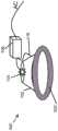
图1示出了根据示例性实施方案的包括智能装饰件的照明器材,该智能装饰件被示出为从照明器材的外壳拆下;FIG. 1 illustrates a lighting fixture including a smart trim, shown detached from a housing of the lighting fixture, according to an exemplary embodiment;

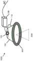
图2示出了根据另一个示例性实施方案的包括智能装饰件的照明器材,该智能装饰件被示出为从照明器材的外壳拆下;2 illustrates a lighting fixture including a smart decor shown detached from a housing of the lighting fixture according to another exemplary embodiment;

图3A至图3D示出了根据示例性实施方案的被配置为用于不同的通信标准的智能装饰件;3A-3D illustrate a smart ornament configured for different communication standards, according to an exemplary embodiment;

图4示出了根据示例性实施方案的包括被配置为用于蓝牙通信的智能装饰件的照明器材;4 illustrates a lighting fixture including a smart trim configured for Bluetooth communication, according to an exemplary embodiment;

图5A至图5D示出了根据示例性实施方案的被配置为用于不同的色温的智能装饰件;5A-5D illustrate a smart trim configured for different color temperatures, according to an exemplary embodiment;

图6示出了根据示例性实施方案的包括被配置为用于2700K色温的智能装饰件的照明器材;6 illustrates a lighting fixture including a smart trim configured for a 2700K color temperature according to an exemplary embodiment;

图7示出了根据示例性实施方案的具有语音能力的智能装饰件;FIG. 7 illustrates a voice-capable smart decorative piece according to an exemplary embodiment;

图8示出了根据示例性实施方案的具有集成相机的智能装饰件;FIG. 8 illustrates a smart trim with an integrated camera according to an exemplary embodiment;

图9示出了根据示例性实施方案的具有集成投影仪的智能装饰件;Figure 9 illustrates a smart trim with an integrated projector according to an exemplary embodiment;

图10示出了根据示例性实施方案的包括具有集成投影仪的智能装饰件的照明器材;10 illustrates a lighting fixture including a smart decor with an integrated projector, according to an exemplary embodiment;

图11示出了根据示例性实施方案的具有图7的智能装饰件的照明器材的框图;11 illustrates a block diagram of a lighting fixture having the smart trim of FIG. 7 according to an exemplary embodiment;

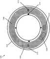
图12示出了根据示例性实施方案的智能装饰件的顶部平面视图;Figure 12 illustrates a top plan view of a smart trim piece according to an exemplary embodiment;

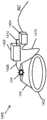
图13示出了根据示例性实施方案的包括智能装饰件和专用电力模块的照明器材;Figure 13 illustrates a lighting fixture including a smart trim and a dedicated power module, according to an exemplary embodiment;

图14示出了根据另一个示例性实施方案的包括智能装饰件和专用电力模块的照明器材;Figure 14 illustrates a lighting fixture including a smart trim and a dedicated power module, according to another exemplary embodiment;

图15示出了根据示例性实施方案的智能装饰件的电力和通信连接;Figure 15 illustrates the power and communication connections of a smart trim piece according to an exemplary embodiment;

图16示出了根据另一个示例性实施方案的智能装饰件的电力和通信连接;并且Figure 16 illustrates the power and communication connections of a smart trim piece according to another exemplary embodiment; and

图17示出了根据另一个示例性实施方案的智能装饰件的电力和通信连接。Figure 17 illustrates the power and communication connections of a smart trim piece according to another exemplary embodiment.

附图仅示出示例性实施方案,因此不应认为是对范围的限制。附图中示出的元件和特征部未必按比例绘制,而是将重点放在清楚地说明示例性实施方案的原理上。另外,可以放大某些尺寸或布置以有助于在视觉上传达此类原理。在附图中,不同的附图中使用的相同的附图标记表示相似或对应但不一定相同的元件。The drawings illustrate only exemplary embodiments and are therefore not to be considered limiting of scope. The elements and features shown in the figures are not necessarily drawn to scale, emphasis instead being placed upon clearly illustrating the principles of the example embodiments. Additionally, certain dimensions or arrangements may be exaggerated to help visually convey such principles. In the figures, the use of the same reference numerals in different figures indicates similar or corresponding, but not necessarily identical, elements.

具体实施方式Detailed ways

在以下段落中,将参考附图进一步详细描述示例性实施方案。在本说明书中,省略或简要描述了众所周知的部件、方法和/或处理技术。此外,对实施方案的各种特征的引用并非暗示所有实施方案必须包括所引用的特征。In the following paragraphs, exemplary embodiments will be described in further detail with reference to the accompanying drawings. In this specification, well-known components, methods and/or processing techniques are omitted or briefly described. Furthermore, reference to various features of an embodiment does not imply that all embodiments must include the recited feature.

在一些示例性实施方案中,装饰件可以用作嵌入式照明器材的模块化结构,以允许将各种感测和其他能力添加到照明器材。可以将各种部件放置在例如装饰件的从天花板下方不可见的背面。例如,可以将部件放置在安装在装饰件的背面的单个印刷电路板(PCB)上。另选地,可以将不同的部件安装在装饰件上的各种位置处。例如,可以将部件放置在装饰件的背面、正面或侧面,或者放置在从装饰件的背面延伸的挡板或其他结构上。In some exemplary embodiments, the trim can be used as a modular structure for recessed lighting fixtures, allowing various sensing and other capabilities to be added to the lighting fixtures. Various components can be placed, for example, on the back side of the trim which is not visible from below the ceiling. For example, components may be placed on a single printed circuit board (PCB) mounted on the back of the trim. Alternatively, different components may be mounted at various locations on the trim. For example, components may be placed on the back, front, or sides of the trim, or on a bezel or other structure extending from the back of the trim.

在一些示例性实施方案中,嵌入式照明器材可以提供用于向和从设置在例如装饰件的背面或设置在从装饰件延伸的挡板上的部件的电力和通信连接的平台。在一些情况下,装饰件可以具有敞口和/或开口,以容纳传感器和需要被定位成暴露于在天花板下方的空间的其他部件。可结合在装饰件中的硬件的非排他性示例包括一个或多个处理器、无线电或收发器、开关、麦克风、扬声器、相机、投影仪、电池和指示器灯。可结合在装饰件中的传感器的非排他性示例包括一个或多个光电单元、占用传感器、一氧化碳传感器、烟雾传感器、二氧化碳传感器、湿度传感器、温度传感器和空气质量传感器。装饰件可附接到现有基础装饰件,以允许将新能力和特征添加到照明器材。装饰件还可以是可更换的装饰件,以允许将不同或更新的能力添加到照明器材。通常,通过利用在天花板与装饰件之间的暴露空间以及装饰件的模块性,最终用户可以容易地改变和/或配置其器材的各种连接和感测特征。In some exemplary embodiments, a recessed lighting fixture may provide a platform for power and communication connections to and from components disposed, for example, on the back of a trim piece or on a bezel extending from the trim piece. In some cases, trim pieces may have openings and/or openings to accommodate sensors and other components that need to be positioned exposed to the space below the ceiling. Non-exclusive examples of hardware that may be incorporated into the trim include one or more processors, radios or transceivers, switches, microphones, speakers, cameras, projectors, batteries, and indicator lights. Non-exclusive examples of sensors that may be incorporated into the trim include one or more photoelectric cells, occupancy sensors, carbon monoxide sensors, smoke sensors, carbon dioxide sensors, humidity sensors, temperature sensors, and air quality sensors. Trims can be attached to existing base trims to allow new capabilities and features to be added to the lighting fixture. The trim can also be an interchangeable trim to allow different or newer capabilities to be added to the lighting fixture. In general, by taking advantage of the exposed space between the ceiling and the trim and the modularity of the trim, end users can easily change and/or configure the various connection and sensing features of their fixtures.

现在转向附图,描述了特定的示例性实施方案。图1示出了根据示例性实施方案的包括智能装饰件108的照明器材100,该智能装饰件被示出为从照明器材的外壳102拆下。在一些示例性实施方案中,照明器材100包括外壳102、光源104、驱动器106和智能装饰件108。智能装饰件108可以使用一个或多个附接装置来可移除地/可拆卸地附接到外壳102,该附接装置诸如扭转弹簧、摩擦夹具、卡扣配件、粘合剂、磁体、以及包括突片和狭槽的其他耦接机构中的一者或多者。例如,一个或多个夹具118可以用于将智能装饰件108牢固地附接到外壳102。Turning now to the drawings, certain exemplary embodiments are described. 1 illustrates alighting fixture 100 including asmart decor 108 shown detached from ahousing 102 of the lighting fixture, according to an exemplary embodiment. In some exemplary embodiments,lighting fixture 100 includes ahousing 102 , alight source 104 , adriver 106 , and asmart decor 108 . Thesmart trim 108 may be removably/detachably attached to thehousing 102 using one or more attachment means, such as torsion springs, friction clips, snap fits, adhesives, magnets, and One or more of other coupling mechanisms including tabs and slots. For example, one ormore clips 118 may be used to securely attachsmart trim 108 tohousing 102 .

在一些示例性实施方案中,驱动器106可以经由电缆134接收电力(诸如AC电力)并将输出电力提供到光源104以及智能装饰件108的部件。例如,光源104可以是发光二极管(LED)光源,并且驱动器106可以是或可以包括恒定电流电源,该恒定电流电源经由电缆114将兼容电力提供到光源104。另选地,驱动器106可以是或可以包括电压源。驱动器106还可以经由由连接器130端接的电缆116将电力提供到智能装饰件108。可包括多条电线的电缆116还可以用于在驱动器106与智能装饰件108之间的单向或双向通信。In some exemplary embodiments,driver 106 may receive power (such as AC power) viacable 134 and provide output power tolight source 104 and components ofsmart trim 108 . For example,light source 104 may be a light emitting diode (LED) light source, anddriver 106 may be or may include a constant current power supply that provides compatible power tolight source 104 viacable 114 . Alternatively,driver 106 may be or include a voltage source.Driver 106 may also provide power to smarttrim piece 108 viacable 116 terminated byconnector 130 .Cable 116 , which may include multiple wires, may also be used for one-way or two-way communication betweendriver 106 andsmart trim 108 .

在一些示例性实施方案中,智能装饰件108包括装饰件结构110和PCB 112。装饰件结构110具有外周边和内周边,其中内周边围绕被设计成与外壳102的开口对齐的开口,以允许来自光源104的光离开外壳102。装饰件结构110可以包括一个或多个一个或多个夹具118或可用于将智能装饰件108牢固地附接到外壳102的其他附接结构。一个或多个夹具118或其他附接结构可以将智能装饰件108牢固地附接到外壳102,同时允许智能装饰件108方便地从外壳102拆下。例如,智能装饰件108可以用另一个智能装饰件或常规装饰件更换。In some exemplary embodiments, thesmart trim 108 includes atrim structure 110 and aPCB 112.Trim structure 110 has an outer perimeter and an inner perimeter, where the inner perimeter surrounds an opening designed to align with the opening ofhousing 102 to allow light fromlight source 104 to exithousing 102 .Trim structure 110 may include one ormore clips 118 or other attachment structures that may be used to securely attachsmart trim 108 tohousing 102 . One ormore clips 118 or other attachment structures may securely attachsmart trim 108 tohousing 102 while allowingsmart trim 108 to be easily detached fromhousing 102 . For example, thesmart trim 108 may be replaced with another smart trim or a regular trim.

在一些示例性实施方案中,PCB 112可以在装饰件结构110的背面附接到装饰件结构110,如图1所示,其中当安装照明器材100时,装饰件结构的背面不在由来自光源104的光照射的区域的视图内。例如,可以使用一个或多个紧固件132(诸如夹具)将PCB 112附接到装饰件结构110。代替一个或多个紧固件132或除此之外,可以使用其他附接手段(诸如粘合剂)将PCB 112牢固地附接到装饰件结构110。在一些另选的实施方案中,PCB 112可以在不使用紧固件的情况下定位在装饰件结构110上。In some exemplary embodiments,PCB 112 may be attached to trimstructure 110 at the back oftrim structure 110, as shown in FIG. within the view of the area illuminated by the light. For example, thePCB 112 may be attached to thetrim structure 110 using one ormore fasteners 132, such as clips. Instead of or in addition to one ormore fasteners 132, other attachment means, such as adhesives, may be used to securely attach thePCB 112 to thetrim structure 110. In some alternative embodiments, thePCB 112 can be positioned on thetrim structure 110 without the use of fasteners.

在一些示例性实施方案中,PCB 112可以包括附接到PCB 112的一个或多个侧面的多个部件。例如,PCB 112可以包括处理器(或控制器)120、传感器122、麦克风124和射频天线126。传感器122可以在PCB 112的面向装饰件结构110的侧面上并可以至少部分地设置在装饰件结构110中的孔隙上方以使其在照明器材100安装在天花板上之后暴露于在照明器材100下方的空间。麦克风124也可以在PCB 112的面向装饰件结构110的侧面上并可以至少部分地设置在装饰件结构110中的孔隙上方以允许声音在照明器材100安装在天花板上之后容易地从照明器材100下方到达麦克风124。In some exemplary embodiments,PCB 112 may include multiple components attached to one or more sides ofPCB 112. For example,PCB 112 may include processor (or controller) 120,sensor 122,microphone 124, andradio frequency antenna 126. Thesensor 122 can be on the side of thePCB 112 facing thetrim structure 110 and can be disposed at least partially over an aperture in thetrim structure 110 so that it is exposed to the light below thelighting fixture 100 after thelighting fixture 100 is installed on the ceiling. space. Themicrophone 124 may also be on the side of thePCB 112 facing thetrim structure 110 and may be at least partially disposed over an aperture in thetrim structure 110 to allow sound to easily pass from below thelighting fixture 100 after thelighting fixture 100 is installed on the ceiling. Reachmicrophone 124 .

在一些示例性实施方案中,传感器122可以包括光传感器、占用传感器、一氧化碳传感器、烟雾传感器、二氧化碳传感器、湿度传感器、温度传感器和空气质量传感器中的一者或多者。例如,传感器122可以包括占用传感器(诸如运动传感器(例如,PIR传感器))、相机等。In some exemplary embodiments, thesensors 122 may include one or more of a light sensor, an occupancy sensor, a carbon monoxide sensor, a smoke sensor, a carbon dioxide sensor, a humidity sensor, a temperature sensor, and an air quality sensor. For example,sensors 122 may include occupancy sensors such as motion sensors (eg, PIR sensors), cameras, and the like.

在一些示例性实施方案中,麦克风124可以包括单个麦克风或麦克风阵列。例如,麦克风124可以包括一个或多个模拟麦克风。作为另一个示例,麦克风124可以包括其他部件,诸如放大器和模拟-数字转换器。In some exemplary embodiments,microphone 124 may comprise a single microphone or an array of microphones. For example,microphone 124 may include one or more analog microphones. As another example,microphone 124 may include other components such as amplifiers and analog-to-digital converters.

在一些示例性实施方案中,处理器120可以处理来自传感器122、麦克风124、天线126、以及PCB 112的其他部件的电信号。例如,处理器120可以经由PCB 112中的迹线和/或电线电耦接到传感器122、麦克风124、天线126和其他部件。处理器120可以包括微处理器或微控制器、以及其他部件,诸如存储器设备、电源转换器、模拟-数字转换器和数字-模拟转换器。处理器120还可以包括通信接口和部件,诸如一个或多个串行和/或并行通信接口、有线和/或无线接收器、发射器和/或收发器等。In some exemplary embodiments,processor 120 may process electrical signals fromsensor 122,microphone 124,antenna 126, and other components ofPCB 112. For example,processor 120 may be electrically coupled tosensor 122,microphone 124,antenna 126, and other components via traces and/or wires inPCB 112.Processor 120 may include a microprocessor or microcontroller, as well as other components such as memory devices, power converters, analog-to-digital converters, and digital-to-analog converters.Processor 120 may also include communication interfaces and components, such as one or more serial and/or parallel communication interfaces, wired and/or wireless receivers, transmitters and/or transceivers, and the like.

在一些示例性实施方案中,驱动器106可以经由线缆116将电力提供到智能装饰件108的部件。电缆116可以包括一根或多根电线并可以由连接器130端接。连接器130可以被设计成与连接器128配合,该连接器可以电且物理地耦接(例如,焊接)到PCB 112以提供用于将电力提供到PCB 112的部件和用于向和从PCB 112的部件通信的电接口。为了说明,连接器128可以耦接到PCB 112,其中由驱动器106经由线缆116提供的电力可以被输送到PCB112的其他部件。在一些另选的实施方案中,连接器128可以耦接到附接(例如,焊接)到PCB112的电缆。另选地,可以省略连接器128、130,并且线缆116可以通过其他手段电耦接到PCB112的部件。In some exemplary embodiments,driver 106 may provide power to components ofsmart trim 108 viacable 116 .Cable 116 may include one or more wires and may be terminated byconnector 130 .Connector 130 may be designed to mate withconnector 128, which may be electrically and physically coupled (e.g., soldered) toPCB 112 to provide means for providing power toPCB 112 and for providing power to and from the PCB. 112 electrical interface for component communication. To illustrate,connector 128 may be coupled toPCB 112, where power provided bydriver 106 viacable 116 may be delivered to other components ofPCB 112. In some alternative implementations,connector 128 may be coupled to a cable that is attached (eg, soldered) toPCB 112 . Alternatively,connectors 128, 130 may be omitted, andcable 116 may be electrically coupled to components ofPCB 112 by other means.

在一些示例性实施方案中,处理器120可以经由线缆116将控制信号提供到驱动器106。例如,处理器120可以将控制信号提供到驱动器以打开、关闭、调节由光源104发射的光的暗度水平和/或色温。处理器120可以基于由处理器120从传感器122、麦克风124或经由天线126接收的信号来将控制信号(诸如脉宽调制(PWM)信号)提供到驱动器106。另选地或除此之外,PCB 112或智能装饰件108的另一个部件可以包括无源部件136(例如,dip开关),该无源部件可以例如在安装期间或在制造时被配置为使得特定照明控制信号(例如,特定暗度水平或色温调节或设定信号)由智能装饰件108经由线缆116提供到驱动器106。PCB 112也可以是硬接线的,使得特定照明控制信号(例如,特定暗度水平或色温调节或设定信号)由智能装饰件108经由线缆116来提供到驱动器106。驱动器106可以基于由智能装饰件108的处理器120提供的照明控制信号来调节提供到光源104的电力以控制/调节由光源104发射的光。In some exemplary embodiments,processor 120 may provide control signals todriver 106 viacable 116 . For example,processor 120 may provide control signals to drivers to turn on, turn off, adjust the darkness level and/or color temperature of light emitted bylight source 104 .Processor 120 may provide control signals, such as pulse width modulated (PWM) signals, todriver 106 based on signals received byprocessor 120 fromsensor 122 ,microphone 124 , or viaantenna 126 . Alternatively or in addition, thePCB 112 or another component of thesmart trim 108 may include a passive component 136 (e.g., a dip switch) that may be configured, for example, during installation or at the time of manufacture such that A particular lighting control signal (eg, a particular darkness level or color temperature adjustment or setting signal) is provided by thesmart trim piece 108 to thedriver 106 via thecable 116 .PCB 112 may also be hardwired such that specific lighting control signals (eg, specific dimming levels or color temperature adjustment or setting signals) are provided bysmart trim 108 todriver 106 viacable 116 . Thedriver 106 may adjust the power provided to thelight source 104 to control/regulate the light emitted by thelight source 104 based on the lighting control signal provided by theprocessor 120 of thesmart trim piece 108 .

在一些示例性实施方案中,处理器120可以经由线缆116从驱动器106接收通信信号并可以处理和/或经由天线126传输由信号传达的信息。处理器120还可以经由天线126传输从传感器120、麦克风124和/或智能装饰件108的其他部件接收的并且/或者通过处理此类信息生成的信息。通常,处理器120可以接收和传输符合一个或多个无线协议(诸如蓝牙、Wi-Fi、ZigBee等)的无线信号。In some exemplary embodiments,processor 120 may receive communication signals fromdriver 106 viacable 116 and may process and/or transmit information conveyed by the signals viaantenna 126 .Processor 120 may also transmit viaantenna 126 information received fromsensor 120 ,microphone 124 , and/or other components ofsmart trim 108 and/or generated by processing such information. In general,processor 120 may receive and transmit wireless signals conforming to one or more wireless protocols (such as Bluetooth, Wi-Fi, ZigBee, etc.).

在一些示例性实施方案中,装饰件结构110可以使用本领域普通技术人员已知的通常用于制造照明器材装饰件的方法由金属、塑料或其他类型的材料制成。在一些示例性实施方案中,智能装饰件108可以包括从装饰件结构110向上延伸到外壳102的腔中的挡板,并且一个或多个部件(例如,传感器)可以附接到该挡板。在一些示例性实施方案中,智能装饰件108可以在PCB 112上、在另一个PCB上、或者作为单独的部件包括其他设备,该其他设备包括一个或多个处理器、麦克风或传感器。智能装饰件108还可以包括一个或多个扬声器、相机、投影仪、电池和指示器光源。In some exemplary embodiments, thetrim structure 110 may be fabricated from metal, plastic, or other types of materials using methods commonly used to manufacture lighting fixture trims known to those of ordinary skill in the art. In some exemplary embodiments,smart trim 108 may include a bezel extending upwardly fromtrim structure 110 into a cavity ofhousing 102 and one or more components (eg, sensors) may be attached to the bezel. In some exemplary embodiments, thesmart trim 108 may include other devices on thePCB 112, on another PCB, or as a separate component, including one or more processors, microphones, or sensors.Smart decoration 108 may also include one or more speakers, cameras, projectors, batteries, and indicator light sources.

将所期望的电子部件和电路(包括微控制器、无线收发器和传感器)与嵌入式照明器材的装饰件集成允许实现控制和连接的器材的模块性。例如,可以通过更换现有装饰件(例如,常规装饰件或其他智能装饰件)或将智能装饰件添加到照明器材来将具有所期望的特征(例如,无线和占用感测能力)的智能装饰件添加到照明器材。将智能装饰件添加到嵌入式照明器材可以避免对为了添加新特征或由于电子部件出现故障而更换照明器材的需要。通过利用智能装饰件(诸如智能装饰件108),客户可以容易地改变包括通信和控制特征的各种特征和/或将其添加到嵌入式照明器材。Integrating the desired electronic components and circuits, including microcontrollers, wireless transceivers, and sensors, with the trim of the recessed lighting fixture allows modularity of the controlled and connected fixtures. For example, smart decorations with desired features (e.g., wireless and occupancy sensing capabilities) can be integrated by replacing existing decorations (e.g., conventional decorations or other smart decorations) or adding smart decorations to lighting fixtures. pieces are added to lighting fixtures. Adding smart trim to recessed lighting fixtures can avoid the need to replace lighting fixtures in order to add new features or due to failure of electronic components. By utilizing a smart trim, such assmart trim 108, customers can easily change and/or add various features, including communication and control features, to recessed lighting fixtures.

在一些示例性实施方案中,照明器材100可以嵌入天花板、墙壁或另一个表面中。在一些另选的实施方案中,PCB 112的部件可以位于与所示的不同的位置。在一些示例性实施方案中,智能装饰件108可以包括多个PCB而不是仅一个PCB 112。在一些示例性实施方案中,代替一个或多个PCB或除此之外,单独的部件可以定位在装饰件结构110上和/或附接到该装饰件结构。例如,可以省略PCB 112,并且这些部件可以是可定位在装饰件结构110上并可经由电线连接的封装过的部件。在一些另选的实施方案中,在不脱离本公开的范围的情况下,智能装饰件108可以包括比所示的更多或更少的部件。在一些另选的实施方案中,在不脱离本公开的范围的情况下,包括智能装饰件108的照明器材100的一个或多个部件可以具有与所示的圆形形状不同的形状。例如,在不脱离本公开的范围的情况下,智能装饰件108可以具有矩形形状、三角形形状、另一种形状、不同的内周边和外周边形状的混合等。为了说明,在不脱离本公开的范围的情况下,装饰件结构110可以具有矩形形状、三角形形状、另一种形状、不同的内周边和外周边形状的混合等。在一些示例性实施方案中,在不脱离本公开的范围的情况下,智能装饰件108可以包括其他部件,该其他部件包括可移动部件。在一些另选的实施方案中,智能装饰件108可以包括例如从装饰件结构110向上延伸的挡板,使得当智能装饰件108附接到外壳102时,该挡板定位在外壳102的腔中。In some exemplary embodiments,lighting fixture 100 may be embedded in a ceiling, wall, or another surface. In some alternative embodiments, components ofPCB 112 may be located in different locations than shown. In some exemplary embodiments, thesmart trim 108 may include multiple PCBs instead of just onePCB 112. In some exemplary embodiments, separate components may be positioned on and/or attached to trimstructure 110 instead of or in addition to one or more PCBs. For example, thePCB 112 can be omitted, and the components can be packaged components that can be positioned on thetrim structure 110 and can be connected via wires. In some alternative embodiments, the smartdecorative piece 108 may include more or fewer components than shown without departing from the scope of the present disclosure. In some alternative embodiments, one or more components oflighting fixture 100 , includingsmart decor piece 108 , may have a different shape than the illustrated circular shape without departing from the scope of the present disclosure. For example, smartdecorative piece 108 may have a rectangular shape, a triangular shape, another shape, a mix of different inner and outer perimeter shapes, etc. without departing from the scope of this disclosure. To illustrate,trim structure 110 may have a rectangular shape, a triangular shape, another shape, a mix of different inner and outer perimeter shapes, etc., without departing from the scope of the present disclosure. In some exemplary embodiments, the smartdecorative piece 108 may include other components, including movable components, without departing from the scope of this disclosure. In some alternative embodiments,smart trim 108 may include, for example, a bezel extending upwardly fromtrim structure 110 such that whensmart trim 108 is attached tohousing 102, the bezel is positioned within the cavity ofhousing 102 .

图2示出了根据另一个示例性实施方案的包括智能装饰件202的照明器材200,该智能装饰件被示出为从照明器材202的外壳102拆下。在一些示例性实施方案中,照明器材200包括外壳102、光源104和驱动器106。例如,驱动器106和光源104可以以关于照明器材100描述的相同的方式操作以将电力提供到光源104。在一些示例性实施方案中,照明器材200包括智能装饰件202和基础装饰件204。基础装饰件204可以由附接装置(诸如一个或多个紧固件)附接到外壳102,或者可以与外壳102一体地形成。例如,当在没有智能装饰件202的情况下安装照明器材200时,基础装饰件204可以用作嵌入式照明器材装饰件。2 illustrates alighting fixture 200 including asmart decor 202 shown detached from thehousing 102 of thelighting fixture 202, according to another exemplary embodiment. In some exemplary embodiments,lighting fixture 200 includeshousing 102 ,light source 104 anddriver 106 . For example,driver 106 andlight source 104 may operate in the same manner as described with respect tolighting fixture 100 to provide power tolight source 104 . In some exemplary embodiments,lighting fixture 200 includessmart trim 202 andbase trim 204 . Thebase trim 204 may be attached to thehousing 102 by attachment means, such as one or more fasteners, or may be integrally formed with thehousing 102 . For example,base trim 204 may serve as a recessed lighting fixture trim whenlighting fixture 200 is installed withoutsmart trim 202 .

在一些示例性实施方案中,智能装饰件202可以包括装饰件结构210和参照图1描述的PCB 112。装饰件结构210具有外周边和内周边,其中内周边围绕被设计成与外壳102的开口对齐的开口,以允许来自光源104的光离开外壳102。PCB 112可以包括处理器120、传感器122、麦克风124、天线126、以及关于智能装饰件108描述的其他部件。如上面关于照明器材100所述,处理器120可以接收和处理来自传感器122和来自麦克风124的信号并经由天线126传输无线信号。此外,处理器120可以经由线缆116将照明控制信号提供到驱动器106以打开、关闭和/或调节由光源104发射的光的暗度水平、色温等。驱动器106还可以经由线缆116或另一根电缆从驱动器106接收通信信号。In some exemplary embodiments,smart trim 202 may includetrim structure 210 andPCB 112 as described with reference to FIG. 1 .Trim structure 210 has an outer perimeter and an inner perimeter, where the inner perimeter surrounds an opening designed to align with the opening ofhousing 102 to allow light fromlight source 104 to exithousing 102 .PCB 112 may includeprocessor 120,sensor 122,microphone 124,antenna 126, and other components described with respect tosmart trim piece 108. As described above with respect tolighting fixture 100 ,processor 120 may receive and process signals fromsensor 122 and frommicrophone 124 and transmit wireless signals viaantenna 126 . Additionally,processor 120 may provide lighting control signals todriver 106 viacable 116 to turn on, off, and/or adjust the dimming level, color temperature, etc. of light emitted bylight source 104 .Driver 106 may also receive communication signals fromdriver 106 viacable 116 or another cable.

在一些示例性实施方案中,装饰件结构210也可以与上述装饰件结构110相同或基本上类似。例如,装饰件结构210可以由与装饰件结构110相同的材料和/或以相同的方式制成。PCB 112还可以以与关于智能装饰件108描述的相同的方式附接到装饰件结构210。In some exemplary embodiments, thetrim structure 210 may also be the same as or substantially similar to thetrim structure 110 described above. For example,trim structure 210 may be made of the same material and/or in the same manner astrim structure 110 .PCB 112 may also be attached to trimstructure 210 in the same manner as described with respect tosmart trim 108.

在一些示例性实施方案中,智能装饰件202可以使用一个或多个附接装置来牢固地但可移除地附接到外壳102或基础装饰件204,该附接装置诸如扭转弹簧、摩擦夹具、卡扣配件、粘合剂、磁体、以及包括突片和狭槽的其他耦接机构中的一者或多者。例如,一个或多个夹具208可以用于将智能装饰件202牢固地且可移除地附接到基础装饰件204。In some exemplary embodiments,smart trim piece 202 may be securely but removably attached tohousing 102 or basetrim piece 204 using one or more attachment devices, such as torsion springs, friction clips, , snap fittings, adhesives, magnets, and other coupling mechanisms including tabs and slots. For example, one ormore clips 208 may be used to securely and removably attachsmart trim piece 202 to basetrim piece 204 .

在一些示例性实施方案中,基础装饰件204可以包括孔206,该孔用于将电缆116布线到智能装饰件202。端接线缆130的连接器130被设计成与智能装饰件202的连接器128配合。孔206可以通过去除基础装饰件204中的敲凿部分或通过在基础装饰件204中切出孔206来形成。在一些另选的实施方案中,可以省略孔206,并且线缆116和连接器可以围绕基础装饰件204的外周边延伸到PCB 112。例如,装饰件结构210可以具有比基础装饰件204的外径更大的外径。在一些另选的实施方案中,可以省略连接器128、130,并且线缆116可以通过其他手段电耦接到PCB 112的部件。In some exemplary embodiments,base trim 204 may includeholes 206 for routingcables 116 tosmart trim 202 .Connector 130 terminatingcable 130 is designed to mate withconnector 128 ofsmart trim 202 . Thehole 206 may be formed by removing a knockout portion in thebase trim 204 or by cutting thehole 206 in thebase trim 204 . In some alternative embodiments, theholes 206 may be omitted, and thecables 116 and connectors may extend around the outer perimeter of thebase trim 204 to thePCB 112. For example, thetrim structure 210 may have a larger outer diameter than the outer diameter of thebase trim 204 . In some alternative embodiments, theconnectors 128, 130 may be omitted, and thecable 116 may be electrically coupled to components of thePCB 112 by other means.

在一些示例性实施方案中,智能装饰件202可以用于以与上面关于智能装饰件108描述的相同的方式来调节和/或添加到照明器材200的特征。通过利用智能装饰件(诸如智能装饰件202),客户可以容易地改变包括通信和控制特征的各种特征和/或将其添加到嵌入式照明器材。In some exemplary embodiments,smart decor 202 may be used to adjust and/or add features tolighting fixture 200 in the same manner as described above with respect tosmart decor 108 . By utilizing a smart trim such assmart trim 202, customers can easily change and/or add various features, including communication and control features, to a recessed lighting fixture.

在一些另选的实施方案中,PCB 112的部件可以位于与所示的不同的位置。在一些示例性实施方案中,智能装饰件202可以包括多个PCB而不是仅一个PCB 112。在一些示例性实施方案中,代替一个或多个PCB或除此之外,单独的部件可以定位在装饰件结构210上和/或附接到该装饰件结构。在一些另选的实施方案中,在不脱离本公开的范围的情况下,智能装饰件可以包括比所示的更多或更少的部件。在一些另选的实施方案中,在不脱离本公开的范围的情况下,包括智能装饰件202的照明器材200的一个或多个部件可以具有与所示的不同的形状。例如,在不脱离本公开的范围的情况下,智能装饰件202可以具有矩形形状、三角形形状、不同的内周边和外周边形状的混合等。为了说明,在不脱离本公开的范围的情况下,装饰件结构210可以具有矩形形状、三角形形状、另一种形状、不同的内周边和外周边形状的混合等。在一些示例性实施方案中,在不脱离本公开的范围的情况下,智能装饰件202可以包括其他部件,该其他部件包括可移动部件。在一些另选的实施方案中,智能装饰件202可以包括例如从装饰件结构210向上延伸的挡板,使得当智能装饰件108附接到外壳102或附接到基础装饰件204时,该挡板定位在外壳102的腔中。In some alternative embodiments, components ofPCB 112 may be located in different locations than shown. In some exemplary embodiments,smart trim 202 may include multiple PCBs instead of just onePCB 112. In some exemplary embodiments, separate components may be positioned on and/or attached to trimstructure 210 instead of or in addition to one or more PCBs. In some alternative embodiments, the smart trim may include more or fewer components than shown without departing from the scope of the present disclosure. In some alternative embodiments, one or more components oflighting fixture 200 , includingsmart decor 202 , may have a different shape than that shown without departing from the scope of the present disclosure. For example, smartdecorative piece 202 may have a rectangular shape, a triangular shape, a mix of different inner and outer perimeter shapes, etc. without departing from the scope of this disclosure. To illustrate,trim structure 210 may have a rectangular shape, a triangular shape, another shape, a mix of different inner and outer perimeter shapes, etc., without departing from the scope of the present disclosure. In some exemplary embodiments, smartdecorative piece 202 may include other components, including movable components, without departing from the scope of this disclosure. In some alternative embodiments,smart trim 202 may include, for example, a bezel extending upwardly fromtrim structure 210 such that whensmart trim 108 is attached tohousing 102 or tobase trim 204 , the barrier The board is positioned in the cavity of thehousing 102 .

图3A至图3D示出了根据示例性实施方案的被配置为用于不同的通信标准的智能装饰件302至308。在一些示例性实施方案中,智能装饰件302可以对应于图1的智能装饰件108,其中智能装饰件108的PCB 112包括处理器120,该处理器被配置为基于ZigBee无线通信标准来无线地通信。智能装饰件302可以另选地对应于图2的智能装饰件202,其中智能装饰件202的PCB 112包括处理器120,该处理器被配置为基于ZigBee无线通信标准来无线地通信。如上面关于智能装饰件108、202描述的,智能装饰件302的处理器可以包括收发器,该收发器用于例如经由智能装饰件302的天线来传输和接收无线信号。智能装饰件302的处理器还可以包括微处理器、微控制器和其他部件/电路,并且可以执行存储在处理器的存储器设备中的软件代码以传输和接收符合ZigBee无线通信标准的无线信号。3A-3D illustrate smart decorative pieces 302-308 configured for different communication standards, according to example embodiments. In some exemplary embodiments, smartdecorative piece 302 may correspond to smartdecorative piece 108 of FIG. 1 , whereinPCB 112 of smartdecorative piece 108 includesprocessor 120 configured to wirelessly communication. Smartdecorative piece 302 may alternatively correspond to smartdecorative piece 202 of FIG. 2 , whereinPCB 112 of smartdecorative piece 202 includesprocessor 120 configured to communicate wirelessly based on the ZigBee wireless communication standard. As described above with respect to thesmart trim 108 , 202 , the processor of thesmart trim 302 may include a transceiver for transmitting and receiving wireless signals, eg, via an antenna of thesmart trim 302 . The processor of thesmart decoration 302 may also include a microprocessor, a microcontroller and other components/circuits, and may execute software codes stored in the memory device of the processor to transmit and receive wireless signals conforming to the ZigBee wireless communication standard.

在一些示例性实施方案中,智能装饰件304可以对应于图1的智能装饰件108,其中PCB 112包括处理器120,该处理器被配置为基于蓝牙无线通信标准来无线地通信。智能装饰件304可以另选地对应于图2的智能装饰件202,其中PCB 112包括处理器120,该处理器被配置为基于蓝牙无线通信标准来无线地通信。如上面关于智能装饰件108、202描述的,智能装饰件304的处理器可以包括收发器,该收发器用于例如经由智能装饰件304的天线来传输和接收无线信号。智能装饰件304的处理器还可以包括微处理器、微控制器和其他部件/电路,并且可以执行存储在处理器的存储器设备中的软件代码以传输和接收符合蓝牙无线通信标准的无线信号。In some exemplary embodiments, smartdecorative piece 304 may correspond to smartdecorative piece 108 of FIG. 1 , whereinPCB 112 includesprocessor 120 configured to communicate wirelessly based on the Bluetooth wireless communication standard. Smartdecorative piece 304 may alternatively correspond to smartdecorative piece 202 of FIG. 2 , whereinPCB 112 includesprocessor 120 configured to communicate wirelessly based on the Bluetooth wireless communication standard. As described above with respect to thesmart decor piece 108 , 202 , the processor of thesmart decor piece 304 may include a transceiver for transmitting and receiving wireless signals, eg, via an antenna of thesmart decor piece 304 . The processor of thesmart decoration 304 may also include a microprocessor, microcontroller and other components/circuits, and may execute software codes stored in the memory device of the processor to transmit and receive wireless signals conforming to the Bluetooth wireless communication standard.

在一些示例性实施方案中,智能装饰件306可以对应于图1的智能装饰件108,其中PCB 112包括处理器120,该处理器被配置为基于Wi-Fi无线通信标准来无线地通信。智能装饰件306可以另选地对应于图2的智能装饰件202,其中PCB 112包括处理器120,该处理器被配置为基于Wi-Fi无线通信标准来无线地通信。如上面关于智能装饰件108、202描述的,智能装饰件306的处理器可以包括收发器,该收发器用于例如经由智能装饰件306的天线来传输和接收无线信号。智能装饰件306的处理器还可以包括微处理器、微控制器和其他部件/电路,并且可以执行存储在处理器的存储器设备中的软件代码以传输和接收符合Wi-Fi无线通信标准的无线信号。In some exemplary embodiments, smartdecorative piece 306 may correspond to smartdecorative piece 108 of FIG. 1 , whereinPCB 112 includesprocessor 120 configured to communicate wirelessly based on the Wi-Fi wireless communication standard. Smartdecorative piece 306 may alternatively correspond to smartdecorative piece 202 of FIG. 2 , whereinPCB 112 includesprocessor 120 configured to communicate wirelessly based on the Wi-Fi wireless communication standard. As described above with respect to thesmart decor piece 108 , 202 , the processor of thesmart decor piece 306 may include a transceiver for transmitting and receiving wireless signals, eg, via an antenna of thesmart decor piece 306 . The processor of thesmart decoration 306 may also include a microprocessor, a microcontroller, and other components/circuits, and may execute software codes stored in the memory device of the processor to transmit and receive wireless communications conforming to the Wi-Fi wireless communication standard. Signal.

在一些示例性实施方案中,智能装饰件308可以对应于图1的智能装饰件108,其中PCB 112包括处理器120,该处理器被配置为基于Z-Wave无线通信协议来无线地通信。智能装饰件308可以另选地对应于图2的智能装饰件202,其中PCB 112包括处理器120,该处理器被配置为基于Z-Wave无线通信协议来无线地通信。如上面关于智能装饰件108、202描述的,智能装饰件308的处理器可以包括收发器,该收发器用于例如经由智能装饰件308的天线来传输和接收无线信号。智能装饰件308的处理器还可以包括微处理器、微控制器和其他部件/电路,并且可以执行存储在处理器的存储器设备中的软件代码以传输和接收符合Z-Wave无线通信协议的无线信号。In some exemplary embodiments, smartdecorative piece 308 may correspond to smartdecorative piece 108 of FIG. 1 , whereinPCB 112 includesprocessor 120 configured to communicate wirelessly based on the Z-Wave wireless communication protocol. Smartdecorative piece 308 may alternatively correspond to smartdecorative piece 202 of FIG. 2 , whereinPCB 112 includesprocessor 120 configured to communicate wirelessly based on the Z-Wave wireless communication protocol. As described above with respect to thesmart decor piece 108 , 202 , the processor of thesmart decor piece 308 may include a transceiver for transmitting and receiving wireless signals, eg, via an antenna of thesmart decor piece 308 . The processor of thesmart decoration 308 may also include a microprocessor, a microcontroller, and other components/circuits, and may execute software codes stored in the memory device of the processor to transmit and receive wireless communications conforming to the Z-Wave wireless communication protocol. Signal.

在一些示例性实施方案中,在不脱离本公开的范围的情况下,智能装饰件302至308可以各自包括除PCB 112以外的PCB。在一些示例性实施方案中,智能装饰件302至308可以各自支持符合其他通信标准的通信。在一些另选的实施方案中,智能装饰件302至308可以各自包括具有附加部件和/或不具有上面关于智能装饰件108、202描述的部件中的一些部件的PCB 112。在一些另选的实施方案中,在不脱离本公开的范围的情况下,智能装饰件302至308可以各自具有与所示的不同的形状。In some exemplary embodiments, smart trim pieces 302-308 may each include a PCB other thanPCB 112 without departing from the scope of the present disclosure. In some exemplary embodiments, smart decorative pieces 302-308 may each support communications in accordance with other communications standards. In some alternative embodiments, the smart trim pieces 302-308 may each include thePCB 112 with additional components and/or without some of the components described above with respect to thesmart trim pieces 108, 202. In some alternative embodiments, smart decorative pieces 302-308 may each have a different shape than that shown without departing from the scope of the present disclosure.

图4示出了根据示例性实施方案的包括被配置为用于蓝牙通信的智能装饰件304的照明器材400。参照图1至图4,在一些示例性实施方案中,照明器材400可以对应于照明器材100或照明器材200。例如,如关于照明器材100描述的,智能装饰件304可以附接到外壳102。另选地,如关于照明器材200描述的,智能装饰件304可以附接到基础装饰件,诸如基础装饰件204。FIG. 4 illustrates alighting fixture 400 including asmart decor piece 304 configured for Bluetooth communication, according to an exemplary embodiment. Referring to FIGS. 1-4 , in some exemplary embodiments,lighting fixture 400 may correspond tolighting fixture 100 orlighting fixture 200 . For example,smart decor 304 may be attached tohousing 102 as described with respect tolighting fixture 100 . Alternatively,smart trim 304 may be attached to a base trim, such asbase trim 204 , as described with respect tolighting fixture 200 .

在一些示例性实施方案中,智能装饰件304可以接收和处理蓝牙信号并基于接收到的蓝牙信号来执行功能,诸如控制照明器材400的光源104。为了说明,智能装饰件304的处理器可以经由线缆116将照明控制信号提供到驱动器106以控制由驱动器106提供到光源104的电力。In some exemplary embodiments, thesmart decoration 304 may receive and process Bluetooth signals and perform functions based on the received Bluetooth signals, such as controlling thelight sources 104 of thelighting fixture 400 . To illustrate, the processor of thesmart trim piece 304 may provide a lighting control signal to thedriver 106 via thecable 116 to control the power provided by thedriver 106 to thelight source 104 .

在一些另选的实施方案中,智能装饰件302、智能装饰件306和智能装饰件308可以各自用来代替照明器材400中的智能装饰件304。例如,智能装饰件304可以可移除地附接到外壳102或基础装饰件204(当存在时),并且智能装饰件304可以用另一个智能装饰件更换以提供不同的通信能力。在一些另选的实施方案中,智能装饰件304可以具有与符合包括ZigBee、Wi-Fi和Z-Wave的其他无线通信标准的无线信号无线地通信的能力。In some alternative embodiments,smart decor 302 ,smart decor 306 , andsmart decor 308 may each be used in place ofsmart decor 304 inlighting fixture 400 . For example,smart trim piece 304 may be removably attached tohousing 102 or base trim piece 204 (when present), and smarttrim piece 304 may be replaced with another smart trim piece to provide different communication capabilities. In some alternative embodiments, the smartdecorative piece 304 may have the capability to communicate wirelessly with wireless signals conforming to other wireless communication standards including ZigBee, Wi-Fi, and Z-Wave.

图5A至图5D示出了根据示例性实施方案的被配置为用于不同的色温的智能装饰件502至508。在一些示例性实施方案中,图5A的智能装饰件502可以对应于图1的智能装饰件108,其中智能装饰件108的PCB 112包括处理器120,该处理器被配置为提供照明控制信号(例如,一个或多个PWM信号或CCT设定信号),该照明控制信号意图产生具有2700K的相关色温(CCT)的光。智能装饰件502可以另选地对应于图2的智能装饰件202,其中智能装饰件108的PCB 112包括处理器120,该处理器被配置为提供照明控制信号(例如,一个或多个PWM信号或CCT设定信号),该照明控制信号意图产生具有2700K的相关色温(CCT)的光。在一些另选的实施方案中,智能装饰件502可以被硬接线以提供照明控制信号,该照明控制信号意图产生具有2700K的相关色温(CCT)的光。在又一些另选的实施方案中,智能装饰件502可以包括无源部件,诸如可设定为选择多个CCT设定中的一个CCT设定的dip开关,使得智能装饰件502提供照明控制信号,该照明控制信号意图产生具有2700K的相关色温(CCT)的光。5A-5D illustrate smart decorative pieces 502-508 configured for different color temperatures, according to example embodiments. In some exemplary embodiments, thesmart trim 502 of FIG. 5A may correspond to thesmart trim 108 of FIG. 1 , wherein thePCB 112 of thesmart trim 108 includes aprocessor 120 configured to provide a lighting control signal ( For example, one or more PWM signals or CCT setting signals), the lighting control signal is intended to produce light with a correlated color temperature (CCT) of 2700K.Smart trim 502 may alternatively correspond tosmart trim 202 of FIG. 2 , whereinPCB 112 ofsmart trim 108 includesprocessor 120 configured to provide lighting control signals (e.g., one or more PWM or CCT setting signal), the lighting control signal is intended to produce light with a correlated color temperature (CCT) of 2700K. In some alternative embodiments, thesmart trim 502 may be hardwired to provide a lighting control signal intended to produce light with a correlated color temperature (CCT) of 2700K. In yet other alternative embodiments, thesmart trim 502 can include passive components, such as a dip switch that can be set to select one of a plurality of CCT settings, such that thesmart trim 502 provides a lighting control signal , the lighting control signal is intended to produce light with a correlated color temperature (CCT) of 2700K.

在一些示例性实施方案中,图5B的智能装饰件504可以对应于图1的智能装饰件108,其中智能装饰件108的PCB 112包括处理器120,该处理器被配置为提供照明控制信号(例如,一个或多个PWM信号或CCT设定信号),该照明控制信号意图产生具有3000K的相关色温(CCT)的光。智能装饰件504可以另选地对应于图2的智能装饰件202,其中智能装饰件108的PCB 112包括处理器120,该处理器被配置为提供照明控制信号(例如,一个或多个PWM信号或CCT设定信号),该照明控制信号意图产生具有3000K的相关色温(CCT)的光。在一些另选的实施方案中,智能装饰件504可以被硬接线以提供照明控制信号,该照明控制信号意图产生具有3000K的相关色温(CCT)的光。在又一些另选的实施方案中,智能装饰件504可以包括无源部件,诸如可设定为选择多个CCT设定中的一个CCT设定的dip开关,使得智能装饰件504提供照明控制信号,该照明控制信号意图产生具有3000K的相关色温(CCT)的光。In some exemplary embodiments, thesmart trim 504 of FIG. 5B may correspond to thesmart trim 108 of FIG. 1 , wherein thePCB 112 of thesmart trim 108 includes aprocessor 120 configured to provide a lighting control signal ( For example, one or more PWM signals or CCT setting signals), the lighting control signal is intended to produce light with a correlated color temperature (CCT) of 3000K.Smart trim 504 may alternatively correspond tosmart trim 202 of FIG. or CCT setting signal), the lighting control signal is intended to produce light with a correlated color temperature (CCT) of 3000K. In some alternative embodiments, thesmart trim 504 may be hardwired to provide a lighting control signal intended to produce light with a correlated color temperature (CCT) of 3000K. In yet other alternative embodiments, thesmart trim 504 can include passive components, such as a dip switch that can be set to select one of a plurality of CCT settings, such that thesmart trim 504 provides a lighting control signal , the lighting control signal is intended to produce light with a correlated color temperature (CCT) of 3000K.

在一些示例性实施方案中,图5C的智能装饰件506可以对应于图1的智能装饰件108,其中智能装饰件108的PCB 112包括处理器120,该处理器被配置为提供照明控制信号(例如,一个或多个PWM信号或CCT设定信号),该照明控制信号意图产生具有4000K的相关色温(CCT)的光。智能装饰件506可以另选地对应于图2的智能装饰件202,其中智能装饰件108的PCB 112包括处理器120,该处理器被配置为提供照明控制信号(例如,一个或多个PWM信号或CCT设定信号),该照明控制信号意图产生具有4000K的相关色温(CCT)的光。在一些另选的实施方案中,智能装饰件506可以被硬接线以提供照明控制信号,该照明控制信号意图产生具有4000K的相关色温(CCT)的光。在又一些另选的实施方案中,智能装饰件506可以包括无源部件,诸如可设定为选择多个CCT设定中的一个CCT设定的dip开关,使得智能装饰件506提供照明控制信号,该照明控制信号意图产生具有4000K的相关色温(CCT)的光。In some exemplary embodiments, thesmart trim 506 of FIG. 5C may correspond to thesmart trim 108 of FIG. 1 , wherein thePCB 112 of thesmart trim 108 includes aprocessor 120 configured to provide a lighting control signal ( For example, one or more PWM signals or CCT setting signals), the lighting control signal is intended to produce light with a correlated color temperature (CCT) of 4000K.Smart trim 506 may alternatively correspond tosmart trim 202 of FIG. or CCT setting signal), the lighting control signal is intended to produce light with a correlated color temperature (CCT) of 4000K. In some alternative embodiments, thesmart trim 506 may be hardwired to provide a lighting control signal intended to produce light with a correlated color temperature (CCT) of 4000K. In yet other alternative embodiments, thesmart trim 506 may include passive components such as a dip switch that may be set to select one of a plurality of CCT settings such that thesmart trim 506 provides a lighting control signal , the lighting control signal is intended to produce light with a correlated color temperature (CCT) of 4000K.

在一些示例性实施方案中,图5D的智能装饰件508可以对应于图1的智能装饰件108,其中智能装饰件108的PCB 112包括处理器120,该处理器被配置为提供照明控制信号(例如,一个或多个PWM信号或CCT设定信号),该照明控制信号意图产生具有5000K的相关色温(CCT)的光。智能装饰件506可以另选地对应于图2的智能装饰件202,其中智能装饰件108的PCB 112包括处理器120,该处理器被配置为提供照明控制信号(例如,一个或多个PWM信号或CCT设定信号),该照明控制信号意图产生具有5000K的相关色温(CCT)的光。在一些另选的实施方案中,智能装饰件506可以被硬接线以提供照明控制信号,该照明控制信号意图产生具有5000K的相关色温(CCT)的光。在又一些另选的实施方案中,智能装饰件506可以包括无源部件,诸如可设定为选择多个CCT设定中的一个CCT设定的dip开关,使得智能装饰件506提供照明控制信号,该照明控制信号意图产生具有5000K的相关色温(CCT)的光。In some exemplary embodiments, thesmart trim 508 of FIG. 5D may correspond to thesmart trim 108 of FIG. 1 , wherein thePCB 112 of thesmart trim 108 includes aprocessor 120 configured to provide a lighting control signal ( For example, one or more PWM signals or CCT setting signals), the lighting control signal is intended to produce light with a correlated color temperature (CCT) of 5000K.Smart trim 506 may alternatively correspond tosmart trim 202 of FIG. or CCT setting signal), the lighting control signal is intended to produce light with a correlated color temperature (CCT) of 5000K. In some alternative embodiments, thesmart trim 506 may be hardwired to provide a lighting control signal intended to produce light with a correlated color temperature (CCT) of 5000K. In yet other alternative embodiments, thesmart trim 506 may include passive components such as a dip switch that may be set to select one of a plurality of CCT settings such that thesmart trim 506 provides a lighting control signal , the lighting control signal is intended to produce light with a correlated color temperature (CCT) of 5000K.

在一些示例性实施方案中,在不脱离本公开的范围的情况下,智能装饰件502至508可以各自包括除PCB 112以外的PCB。在一些示例性实施方案中,智能装饰件502至508可以各自支持符合其他通信标准的通信。在一些另选的实施方案中,智能装饰件502至508可以各自包括具有附加部件和/或不具有上面关于智能装饰件108、202描述的部件中的一些部件的PCB 112。在一些另选的实施方案中,在不脱离本公开的范围的情况下,智能装饰件502至508可以各自具有与所示的不同的形状。在一些另选的实施方案中,智能装饰件502至508可以各自被配置为控制信号,该控制信号意图产生具有除上述CCT以外的CCT的光。In some exemplary embodiments, smart trim pieces 502-508 may each include a PCB other thanPCB 112 without departing from the scope of the present disclosure. In some exemplary embodiments, smart decorative pieces 502-508 may each support communications in accordance with other communications standards. In some alternative embodiments, the smart trim pieces 502-508 may each include thePCB 112 with additional components and/or without some of the components described above with respect to thesmart trim pieces 108, 202. In some alternative embodiments, smart decorative pieces 502-508 may each have a different shape than that shown without departing from the scope of the present disclosure. In some alternative embodiments, smart trim pieces 502-508 may each be configured as a control signal intended to produce light having a CCT other than the CCT described above.

图6示出了根据示例性实施方案的包括被配置为用于2700K CCT的图5A的智能装饰件502的照明器材600。参照图1、图2、图5A至图5D和图6,在一些示例性实施方案中,照明器材600可以对应于照明器材100或照明器材200。例如,如关于照明器材100描述的,智能装饰件502可以附接到外壳102。另选地,如关于照明器材200描述的,智能装饰件502可以附接到基础装饰件,诸如基础装饰件204。FIG. 6 illustrates alighting fixture 600 including thesmart trim 502 of FIG. 5A configured for a 2700K CCT, according to an exemplary embodiment. Referring to FIGS. 1 , 2 , 5A-5D , and 6 ,lighting fixture 600 may correspond tolighting fixture 100 orlighting fixture 200 in some exemplary embodiments. For example,smart decor piece 502 may be attached tohousing 102 as described with respect tolighting fixture 100 . Alternatively,smart trim piece 502 may be attached to a base trim piece, such asbase trim piece 204 , as described with respect tolighting fixture 200 .

在一些示例性实施方案中,智能装饰件502可以包括处理器120,该处理器被配置为经由线缆116将照明控制信号(例如,一个或多个PWM信号)提供到驱动器106,并且驱动器106可以调节提供到光源104的电力以将由光源104发射的光的CCT调节或设定为2700K。在一些示例性实施方案中,智能装饰件502的处理器120可以提供一个或多个信号,该一个或多个信号控制驱动器106的CCT设定,其中驱动器106基于该设定来调节提供到光源104的电力。在一些另选的实施方案中,智能装饰件502可以是硬接线的或可以包括无源部件,诸如dip开关,其中智能装饰件502提供控制信号,诸如一个或多个CCT设定信号,该控制信号导致驱动器106将电力提供到光源104,从而产生由光源104发射的具有2700K的CCT的光。In some exemplary embodiments, smartdecorative piece 502 may includeprocessor 120 configured to provide a lighting control signal (eg, one or more PWM signals) todriver 106 viacable 116 , anddriver 106 The power provided to thelight source 104 can be adjusted to adjust or set the CCT of the light emitted by thelight source 104 to 2700K. In some exemplary embodiments,processor 120 ofsmart trim 502 may provide one or more signals that control the CCT setting ofdriver 106, whereindriver 106 adjusts the CCT provided to the light source based on the setting. 104 electricity. In some alternative embodiments, thesmart trim 502 may be hardwired or may include passive components, such as dip switches, where thesmart trim 502 provides a control signal, such as one or more CCT set signals, that control The signal causesdriver 106 to provide power tolight source 104 , thereby producing light emitted bylight source 104 with a CCT of 2700K.

在一些另选的实施方案中,智能装饰件504、智能装饰件506和智能装饰件508可以各自用来代替照明器材600中的智能装饰件502。例如,智能装饰件502可以可移除地附接到外壳102或基础装饰件204(当存在时),并且智能装饰件502可以用另一个智能装饰件更换以改变由光源104提供的光的CCT。In some alternative embodiments,smart decor 504 ,smart decor 506 , andsmart decor 508 may each be used in place ofsmart decor 502 inlighting fixture 600 . For example,smart trim 502 may be removably attached tohousing 102 or base trim 204 (when present), andsmart trim 502 may be replaced with another smart trim to change the CCT of light provided bylight source 104 .

图7示出了根据示例性实施方案的具有语音能力的智能装饰件700。在一些示例性实施方案中,智能装饰件700可以对应于图1的智能装饰件108,其中智能装饰件108的PCB112包括处理器120,该处理器被配置为处理经由一个或多个麦克风(诸如麦克风124)接收的语音。智能装饰件502可以另选地对应于图2的智能装饰件202,其中智能装饰件108的PCB112包括处理器120,该处理器被配置为处理经由一个或多个麦克风(诸如麦克风124)接收的语音。例如,智能装饰件700响应于检测到唤醒词或短语而开始收听语音命令。智能装饰件700可以例如处理接收到的语音命令和/或经由Wi-Fi接口将其传输到远程语音服务的服务器(例如,云服务器),该远程语音服务的服务器可以处理一个或多个信号并将其发送回智能装饰件700或另一个设备。另选地,智能装饰件700可以基于在检测到唤醒词或短语之后接收到的语音命令来控制光源(例如,照明器材100、200的光源104)。FIG. 7 illustrates a voice-enabled smartdecorative piece 700 according to an exemplary embodiment. In some exemplary embodiments, smartdecorative piece 700 may correspond to smartdecorative piece 108 of FIG. 1 , whereinPCB 112 of smartdecorative piece 108 includesprocessor 120 configured to process the The voice received by the microphone 124). Smartdecorative piece 502 may alternatively correspond to smartdecorative piece 202 of FIG. voice. For example, smartdecorative piece 700 begins listening for voice commands in response to detecting a wake word or phrase. Smartdecorative piece 700 may, for example, process received voice commands and/or transmit them via a Wi-Fi interface to a server (e.g., a cloud server) of a remote voice service, which may process one or more signals and Send it back tosmart trim 700 or another device. Alternatively, the smartdecorative piece 700 may control the light source (eg, thelight source 104 of thelighting fixture 100, 200) based on a voice command received after the wake word or phrase is detected.

在一些示例性实施方案中,在不脱离本公开的范围的情况下,智能装饰件700可以包括其他部件,诸如传感器等。在一些另选的实施方案中,在不脱离本公开的范围的情况下,智能装饰件700可以具有与所示的不同的形状。In some exemplary embodiments, thesmart decoration 700 may include other components, such as sensors, etc., without departing from the scope of the present disclosure. In some alternative embodiments, smartdecorative piece 700 may have a different shape than that shown without departing from the scope of the present disclosure.

图8示出了根据示例性实施方案的具有集成相机的智能装饰件800。在一些示例性实施方案中,智能装饰件800可以对应于图1的智能装饰件108,其中智能装饰件108的PCB112包括传感器122,该传感器可以是相机。智能装饰件800可以另选地对应于图2的智能装饰件202,其中智能装饰件108的PCB 112包括传感器122,该传感器可以是相机。智能装饰件800还可以包括处理器,诸如处理器120,该处理器接收、处理和/或传输图像(例如,静态图像或视频图像)。例如,智能装饰件800可以基于由集成相机捕获的图像来经由驱动器(诸如驱动器106)控制光源(诸如光源104)。另选地或除此之外,智能装饰件800可以将图像传输到本地或远程服务器以进行存储和/或处理。FIG. 8 illustrates a smartdecorative piece 800 with an integrated camera, according to an exemplary embodiment. In some exemplary embodiments, smartdecorative piece 800 may correspond to smartdecorative piece 108 of FIG. 1 , whereinPCB 112 of smartdecorative piece 108 includessensor 122 , which may be a camera. Smartdecorative piece 800 may alternatively correspond to smartdecorative piece 202 of FIG. 2 , whereinPCB 112 of smartdecorative piece 108 includessensor 122, which may be a camera. Smartdecorative piece 800 may also include a processor, such asprocessor 120, that receives, processes, and/or transmits images (eg, still images or video images). For example,smart trim 800 may control a light source (such as light source 104 ) via a driver (such as driver 106 ) based on images captured by an integrated camera. Alternatively or in addition, smartdecorative piece 800 may transmit the image to a local or remote server for storage and/or processing.

在一些示例性实施方案中,在不脱离本公开的范围的情况下,智能装饰件800可以包括其他部件,诸如麦克风、扬声器等。在一些另选的实施方案中,在不脱离本公开的范围的情况下,智能装饰件800可以具有与所示的不同的形状。In some exemplary embodiments, thesmart decoration 800 may include other components, such as a microphone, speakers, etc., without departing from the scope of the present disclosure. In some alternative embodiments, smartdecorative piece 800 may have a different shape than that shown without departing from the scope of the present disclosure.

图9示出了根据示例性实施方案的具有集成投影仪906的智能装饰件900。例如,智能装饰件900可以包括图1的智能装饰件108或图2的智能装饰件202。在一些示例性实施方案中,智能装饰件900还可以包括挡板902。例如,智能装饰件900是智能装饰件108或具有附接到其的挡板902的智能装饰件202。FIG. 9 illustrates asmart decor piece 900 with anintegrated projector 906 according to an exemplary embodiment. For example,smart decoration 900 may includesmart decoration 108 of FIG. 1 orsmart decoration 202 of FIG. 2 . In some exemplary embodiments,smart decor 900 may also include abezel 902 . For example,smart trim 900 issmart trim 108 orsmart trim 202 havingbezel 902 attached thereto.

在一些示例性实施方案中,集成投影仪906的一个或多个部件可以定位在挡板902的腔中。例如,集成投影仪906可以包括顶部偏振器层、中间LCD层和下部光学层。In some exemplary embodiments, one or more components ofintegrated projector 906 may be positioned within the cavity ofbaffle 902 . For example,integrated projector 906 may include a top polarizer layer, a middle LCD layer, and a lower optical layer.

在一些示例性实施方案中,智能装饰件900还可以包括扬声器904和/或附接到挡板902的其他部件。例如,智能装饰件900可以以与上面关于智能装饰件108、202描述的相同的方式从驱动器(诸如驱动器106)接收电力。在一些示例性实施方案中,投影仪906可以投影存储在智能装饰件908的存储器设备中的静态图像和视频图像。另选地或除此之外,投影仪906可以投影例如由智能装饰件900的处理器无线地接收的静态图像和视频图像。在一些示例性实施方案中,在不脱离本公开的范围的情况下,智能装饰件900可以包括其他部件。在一些另选的实施方案中,在不脱离本公开的范围的情况下,智能装饰件900可以包括比智能装饰件108、202更少的部件。在一些另选的实施方案中,在不脱离本公开的范围的情况下,智能装饰件900可以具有与所示的不同的形状。In some exemplary embodiments,smart trim 900 may also include aspeaker 904 and/or other components attached tobezel 902 . For example,smart trim 900 may receive power from a driver, such asdriver 106 , in the same manner as described above with respect tosmart trim 108 , 202 . In some exemplary embodiments,projector 906 may project still and video images stored in a memory device of smart decor 908 . Alternatively or in addition,projector 906 may project still images and video images, such as received wirelessly by the processor of smarttrim piece 900 . In some exemplary embodiments,smart decoration 900 may include other components without departing from the scope of the present disclosure. In some alternative embodiments, thesmart ornament 900 may include fewer components than thesmart ornament 108 , 202 without departing from the scope of the present disclosure. In some alternative embodiments, the smartdecorative piece 900 may have a different shape than that shown without departing from the scope of the present disclosure.

图10示出了根据示例性实施方案的包括具有集成投影仪的智能装饰件900的照明器材1000。参照图1、图2、图9和图10,照明器材1000包括外壳102、光源104、驱动器106和智能装饰件900。投影仪906可以使用由光源104发射的光来投影图像。例如,智能装饰件900的处理器120可以以与如上所述的类似的方式经由线缆116控制驱动器106以控制由光源104提供的光以便用于照明目的并用于图像投影目的。FIG. 10 illustrates alighting fixture 1000 including asmart decor piece 900 with an integrated projector, according to an exemplary embodiment. Referring to FIGS. 1 , 2 , 9 and 10 , alighting fixture 1000 includes ahousing 102 , alight source 104 , adriver 106 and asmart decoration 900 .Projector 906 may project images using light emitted bylight source 104 . For example,processor 120 ofsmart decor piece 900 may controldriver 106 viacable 116 to control light provided bylight source 104 for lighting purposes and for image projection purposes in a similar manner as described above.

在一些另选的实施方案中,智能装饰件700和智能装饰件800可以各自用来代替照明器材1000中的智能装饰件900。例如,智能装饰件900可以可拆卸地附接到外壳102或基础装饰件204(当存在时),并且智能装饰件900可以用另一个智能装饰件更换以改变将不同的特征模块化添加到照明器材1000。In some alternative embodiments,smart decoration 700 andsmart decoration 800 may each be used in place ofsmart decoration 900 inlighting fixture 1000 . For example,smart trim 900 can be removably attached tohousing 102 or base trim 204 (when present), andsmart trim 900 can be replaced with another smart trim to change the modularity of adding different features to lighting.Equipment 1000.

图11示出了根据示例性实施方案的包括图7的支持语音的智能装饰件700的照明器材1100的框图。在一些示例性实施方案中,照明器材1100包括光引擎1104,该光引擎包括上述光源104和驱动器。照明器材1100还包括智能装饰件700,该智能装饰件可以包括处理单元1106、音频输入单元1108、音频输出单元110和视觉指示器单元1112。例如,音频输入单元1108可以处理由一个或多个麦克风接收的语音,例如以执行波束形成并检测唤醒词或短语。响应于确定接收到唤醒词或短语,音频输入单元1108可以向处理器单元1106指示处理单元1106应当处理另外的语音命令和/或将其传输到例如云语音服务的服务器。例如,处理单元1106可以经由Wi-Fi收发器传输接收语音命令并可以例如经由Wi-Fi收发器从云服务器接收信息。11 illustrates a block diagram of alighting fixture 1100 including the voice-enabledsmart decoration 700 of FIG. 7, according to an exemplary embodiment. In some exemplary embodiments,lighting fixture 1100 includes alight engine 1104 that includeslight source 104 and a driver as described above.Lighting fixture 1100 also includessmart decor 700 , which may includeprocessing unit 1106 ,audio input unit 1108 ,audio output unit 110 , andvisual indicator unit 1112 . For example,audio input unit 1108 may process speech received by one or more microphones, eg, to perform beamforming and detect wake words or phrases. In response to determining that a wake word or phrase was received, theaudio input unit 1108 may indicate to theprocessor unit 1106 that theprocessing unit 1106 should process and/or transmit additional voice commands to a server, eg, a cloud voice service. For example, theprocessing unit 1106 may transmit and receive voice commands via a Wi-Fi transceiver and may receive information from a cloud server, eg, via a Wi-Fi transceiver.

在一些示例性实施方案中,智能装饰件700可以使用音频输出单元1110的扬声器来提供对经由智能装饰件700的麦克风阵列接收的一些语音命令的音频响应。智能装饰件700还可以使用一个或多个视觉指示器来指示状态,诸如处理单元1106是否响应于检测到唤醒词或短语而唤醒。In some exemplary embodiments,smart decoration piece 700 may use the speaker ofaudio output unit 1110 to provide audio responses to some voice commands received via the microphone array ofsmart decoration piece 700 .Smart ornament 700 may also use one or more visual indicators to indicate a status, such as whetherprocessing unit 1106 is awake in response to detection of a wake word or phrase.

在一些示例性实施方案中,智能装饰件700可以基于由智能装饰件700接收并由云语音服务器或由处理单元1106处理的语音命令来控制光源104。为了说明,驱动器106可以从智能装饰件700接收照明控制信号(例如,PWM1和PWM2)并调节由光源104发射的光。智能装饰件700还可以例如经由一根或多根接线(例如,上面讨论的电缆116)将电力(例如,3.3V和12V)提供到智能装饰件700。In some exemplary embodiments,smart decoration 700 may controllight source 104 based on voice commands received bysmart decoration 700 and processed by a cloud voice server or byprocessing unit 1106 . To illustrate,driver 106 may receive lighting control signals (eg, PWM1 and PWM2 ) fromsmart trim piece 700 and adjust the light emitted bylight source 104 . Thesmart trim piece 700 may also provide electrical power (eg, 3.3V and 12V) to thesmart trim piece 700, eg, via one or more wires (eg, thecables 116 discussed above).

在一些示例性实施方案中,在不脱离本公开的范围的情况下,照明器材1100可以包括其他部件。在一些示例性实施方案中,处理单元1106和音频输入单元1108可以被包括在上面讨论的处理器120中。In some exemplary embodiments,lighting fixture 1100 may include other components without departing from the scope of the present disclosure. In some exemplary embodiments, theprocessing unit 1106 and theaudio input unit 1108 may be included in theprocessor 120 discussed above.

图12示出了根据示例性实施方案的智能装饰件1200的顶部平面视图。在一些示例性实施方案中,智能装饰件1200包括装饰件结构1202和PCB 1204。智能装饰件1200还可以包括处理器1206、音频放大器1208、扬声器1210和一个或多个麦克风1212。例如,音频放大器1208和一个或多个麦克风1212可以经由PCB 1204的接线迹线电耦接到处理器1206。例如,处理器1206可以从一个或多个麦克风1212接收电信号并处理该信号以确定接收到的语音是否是唤醒词或短语。处理器1206可以在确定接收到唤醒词或短语之后处理和/或传输由一个或多个麦克风1212接收的其他语音命令。FIG. 12 illustrates a top plan view of asmart decoration 1200 according to an exemplary embodiment. In some exemplary embodiments, thesmart trim 1200 includes atrim structure 1202 and aPCB 1204. Smartdecorative piece 1200 may also includeprocessor 1206 ,audio amplifier 1208 ,speaker 1210 and one ormore microphones 1212 . For example,audio amplifier 1208 and one ormore microphones 1212 may be electrically coupled toprocessor 1206 via wiring traces ofPCB 1204. For example,processor 1206 may receive electrical signals from one ormore microphones 1212 and process the signals to determine whether the received speech is a wake word or phrase.Processor 1206 may process and/or transmit other voice commands received by one ormore microphones 1212 after determining that a wake word or phrase was received.

在一些示例性实施方案中,处理器1206还可以通过将信号提供到驱动扬声器1210以输出声音的音频放大器1208来经由扬声器1210输出音频信息,诸如对语音命令的响应。处理器1206还可以例如在由云语音服务的服务器处理语音命令之后基于接收到的语音命令来提供照明控制命令。In some exemplary embodiments,processor 1206 may also output audio information, such as a response to a voice command, viaspeaker 1210 by providing a signal toaudio amplifier 1208 that drivesspeaker 1210 to output sound. Theprocessor 1206 may also provide lighting control commands based on received voice commands, eg, after the voice commands are processed by a server of the cloud voice service.

在一些示例性实施方案中,智能装饰件1200包括一个或多个指示器灯,该一个或多个指示器灯可以用于显示状态,诸如处理器1206的状态和/或传感器的状态等。在一些示例性实施方案中,一个或多个附接装置(诸如夹具1214)可以用于将智能装饰件1200可移除地附接到照明器材的外壳或基础装饰件。In some exemplary embodiments, thesmart trim 1200 includes one or more indicator lights that can be used to display status, such as the status of theprocessor 1206 and/or the status of the sensors, among others. In some exemplary embodiments, one or more attachment devices, such asclip 1214, may be used to removably attachsmart trim 1200 to the housing or base trim of a lighting fixture.

在一些示例性实施方案中,智能装饰件1200可以对应于智能装饰件108、202、302至308、502至508、700或800。在一些示例性实施方案中,在不脱离本公开的范围的情况下,智能装饰件1200可以包括比所示的更多或更少的部件。在一些示例性实施方案中,当智能装饰件1200与嵌入式照明器材一起安装在天花板上时,扬声器1210和指示器光源1216可以通过装饰件结构1204中的相应开口暴露或可见,以允许从在智能装饰件1200下方的位置分别听到来自扬声器1210的声音和看到来自指示器光源1216的光。在一些另选的实施方案中,智能装饰件1200可以包括多个PCB而不是PCB 112。在一些另选的实施方案中,在不脱离本公开的范围的情况下,装饰件结构1202和/或PCB 1204可以具有与所示的不同的形状。In some exemplary embodiments, smartdecorative piece 1200 may correspond to smartdecorative piece 108 , 202 , 302 - 308 , 502 - 508 , 700 , or 800 . In some exemplary embodiments,smart decor 1200 may include more or fewer components than shown without departing from the scope of the present disclosure. In some exemplary embodiments, whensmart trim 1200 is mounted on a ceiling with a recessed lighting fixture,speaker 1210 andindicator light source 1216 may be exposed or visible through corresponding openings intrim structure 1204 to allow A location below thesmart trim 1200 hears the sound from thespeaker 1210 and sees the light from theindicator light source 1216, respectively. In some alternative embodiments, smartdecorative piece 1200 may include multiple PCBs instead ofPCB 112. In some alternative embodiments,trim structure 1202 and/orPCB 1204 may have different shapes than that shown without departing from the scope of the present disclosure.

图13示出了根据示例性实施方案的包括智能装饰件1302和专用电力模块1304的照明器材1300。在一些示例性实施方案中,照明器材1300包括上面描述的外壳102和光源104。照明器材1300还可以包括驱动器1306,该驱动器以与上面关于驱动器106描述的类似的方式经由电缆1308将电力提供到光源104。FIG. 13 illustrates alighting fixture 1300 including asmart decor 1302 and adedicated power module 1304 according to an exemplary embodiment. In some exemplary embodiments,lighting fixture 1300 includeshousing 102 andlight source 104 as described above.Lighting fixture 1300 may also include adriver 1306 that provides power tolight source 104 viacable 1308 in a manner similar to that described above with respect todriver 106 .

在一些示例性实施方案中,可以将AC电力提供到电力模块1304和驱动器1306。电力模块1304可以以与上面关于驱动器106描述的类似的方式经由电缆1310将适当的电力(例如,一个或多个DC电力信号)提供到智能装饰件1302。线缆1310可以包括多根电线,这些电线可以用于将电力提供到智能装饰件1302并用于在智能装饰件1302与电力模块1304之间的单向或双向通信。In some exemplary embodiments, AC power may be provided topower module 1304 anddriver 1306 .Power module 1304 may provide appropriate power (eg, one or more DC power signals) tosmart trim piece 1302 viacable 1310 in a similar manner as described above with respect todriver 106 .Cable 1310 may include wires that may be used to provide power tosmart trim 1302 and for one-way or two-way communication betweensmart trim 1302 andpower module 1304 .

在一些示例性实施方案中,智能装饰件1302可以经由线缆1310将照明控制信号提供到电力模块1304。例如,智能装饰件1302可以对应于智能装饰件100、200或上面描述的智能装饰件中的另一个智能装饰件。为了说明,智能装饰件1302可以将一个或多个照明控制信号提供到电力模块1304,并且电力模块1304可以经由电缆1312将接收到的照明控制信号或从接收到的照明控制信号得到的其他信号提供到驱动器1306。例如,电力模块1304可以将调暗和/或CCT控制信号(例如,0V至10V信号、UART信号等)提供到相应地调节提供到光源104的电力的驱动器1306。In some exemplary embodiments, smartdecorative piece 1302 may provide lighting control signals topower module 1304 viacable 1310 . For example,smart decoration 1302 may correspond tosmart decoration 100, 200 or another smart decoration among the smart decorations described above. To illustrate, thesmart trim piece 1302 can provide one or more lighting control signals to thepower module 1304, and thepower module 1304 can provide the received lighting control signal or other signal derived from the received lighting control signal via thecable 1312. to drive 1306 . For example,power module 1304 may provide dimming and/or CCT control signals (eg, 0V to 10V signals, UART signals, etc.) todriver 1306 that adjusts power provided tolight source 104 accordingly.

图14示出了根据另一个示例性实施方案的包括智能装饰件1402和专用电力模块1404的照明器材1400。在一些示例性实施方案中,照明器材1400包括上面描述的外壳102和光源104。照明器材1400还可以包括驱动器1406,该驱动器以与上面关于驱动器106描述的类似的方式经由电缆1408将电力提供到光源104。FIG. 14 illustrates alighting fixture 1400 including asmart decor 1402 and adedicated power module 1404 according to another exemplary embodiment. In some exemplary embodiments,lighting fixture 1400 includeshousing 102 andlight source 104 as described above.Lighting fixture 1400 may also include adriver 1406 that provides power tolight source 104 viacable 1408 in a manner similar to that described above with respect todriver 106 .

在一些示例性实施方案中,可以将AC输入电力信号提供到电力模块1404,该电力模块经由线缆1412将从AC输入电力信号得到的切相电力信号提供到驱动器1406。电力模块1404还可以以与上面关于驱动器106描述的类似的方式经由电缆1310将适当的电力(例如,一个或多个DC电力信号)提供到智能装饰件1402。线缆1410可以包括多根电线,这些电线可以用于将电力提供到智能装饰件1402并用于在智能装饰件1402与电力和通信模块1404之间的单向或双向通信。In some exemplary embodiments, an AC input power signal may be provided topower module 1404 , which provides a phase-cut power signal derived from the AC input power signal todriver 1406 viacable 1412 .Power module 1404 may also provide appropriate power (eg, one or more DC power signals) tosmart trim piece 1402 viacable 1310 in a manner similar to that described above with respect todriver 106 .Cable 1410 may include wires that may be used to provide power tosmart trim 1402 and for one-way or two-way communication betweensmart trim 1402 and power andcommunication module 1404 .

在一些示例性实施方案中,智能装饰件1402可以经由线缆1410将照明控制信号提供到电力模块1404。例如,智能装饰件1402可以对应于智能装饰件100、200或上面描述的智能装饰件中的另一个智能装饰件。为了说明,智能装饰件1402可以将一个或多个照明控制信号提供到电力模块1404,并且电力模块1404可以基于照明控制信号来生成切相电力信号并可以经由电缆1412将切相电力信号提供到驱动器1406。驱动器1306可以基于切相电力信号来调节提供到光源104的电力。在一些示例性实施方案中,智能修饰件1402还可以控制电力模块1404是否提供切相电力信号以控制是否将光源104通电或断电。In some exemplary embodiments, smartdecorative piece 1402 may provide lighting control signals topower module 1404 viacable 1410 . For example,smart decoration 1402 may correspond tosmart decoration 100, 200 or another smart decoration among the smart decorations described above. To illustrate,smart trim piece 1402 may provide one or more lighting control signals topower module 1404, andpower module 1404 may generate a phase-cut power signal based on the lighting control signal and may provide the phase-cut power signal to a driver viacable 1412 1406. Thedriver 1306 can regulate the power provided to thelight source 104 based on the phase cut power signal. In some exemplary embodiments, thesmart trim 1402 can also control whether thepower module 1404 provides a phase cut power signal to control whether to power on or off thelight source 104 .

图15示出了根据示例性实施方案的智能装饰件1502的电力和通信连接。在一些示例性实施方案中,智能装饰件1502可以对应于本文所述的智能装饰件中的一个智能装饰件,其中电力和通信连接如图15所示。例如,电缆1504可以耦接到驱动器(诸如驱动器106),或者耦接到专用电力模块(诸如电力模块1304、1306)。在一些示例性实施方案中,线缆1504可以对应于上面描述的线缆116、1310、1410。线缆1504可以由连接器1506端接,该连接器被设计成与连接器1510配合,该连接器端接电缆1508,该电缆例如耦接到智能装饰件1502的PCB。例如,线缆1508可以焊接到智能装饰件1502的PCB。线缆1508和连接器1510可以用作智能装饰件1502的电力和/或通信接口。在一些示例性实施方案中,连接器1506、1510可以是RJ45连接器或其他类型的连接器。FIG. 15 illustrates power and communication connections of a smartdecorative piece 1502 according to an exemplary embodiment. In some exemplary embodiments, smartdecorative piece 1502 may correspond to one of the smart decorative pieces described herein, wherein the power and communication connections are as shown in FIG. 15 . For example,cable 1504 may be coupled to a driver, such asdriver 106, or to a dedicated power module, such aspower modules 1304, 1306. In some exemplary embodiments,cable 1504 may correspond tocables 116, 1310, 1410 described above.Cable 1504 may be terminated byconnector 1506 designed to mate withconnector 1510 , which terminatescable 1508 coupled to the PCB ofsmart trim 1502 , for example. For example,cable 1508 may be soldered to the PCB ofsmart trim 1502 .Cable 1508 andconnector 1510 may serve as a power and/or communication interface forsmart trim 1502 . In some exemplary embodiments, theconnectors 1506, 1510 may be RJ45 connectors or other types of connectors.

在一些示例性实施方案中,可包括多根电线的线缆1505和1508可以用于将电力提供到智能装饰件1502并用于在连接器1506和1510配合之后在智能装饰件1502与驱动器或电力模块之间的单向或双向通信。在一些示例性实施方案中,在不脱离本公开的范围的情况下,多根线缆和相应连接器可以用来代替单独的线缆1504、1508。In some exemplary embodiments,cables 1505 and 1508 , which may include multiple wires, may be used to provide power tosmart trim 1502 and to communicate betweensmart trim 1502 and a driver or power module afterconnectors 1506 and 1510 are mated. One-way or two-way communication between. In some exemplary embodiments, multiple cables and corresponding connectors may be used in place ofindividual cables 1504, 1508 without departing from the scope of the present disclosure.

图16示出了根据另一个示例性实施方案的智能装饰件1602的电力和通信连接。在一些示例性实施方案中,智能装饰件1602可以对应于本文所述的智能装饰件中的一个智能装饰件,其中电力和通信连接如图16所示。例如,电缆1604可以耦接到驱动器(诸如驱动器106),或者耦接到专用电力模块(诸如电力模块1304、1306)。在一些示例性实施方案中,线缆1604可以对应于上面描述的线缆116、1310、1410。FIG. 16 illustrates power and communication connections of a smartdecorative piece 1602 according to another exemplary embodiment. In some exemplary embodiments, smartdecorative piece 1602 may correspond to one of the smart decorative pieces described herein, wherein the power and communication connections are as shown in FIG. 16 . For example,cable 1604 may be coupled to a driver, such asdriver 106, or to a dedicated power module, such aspower modules 1304, 1306. In some exemplary embodiments,cable 1604 may correspond tocables 116, 1310, 1410 described above.

在一些示例性实施方案中,线缆1604可以端接在磁体1606处,该磁体被设计成磁性地连接到电耦接到智能装饰件1602的PCB的对应磁体1608。磁体1608可以例如通过粘合剂附接到智能装饰件1502的PCB,同时进行与PCB的迹线的电连接。磁体1606和1608可以彼此连接,以经由线缆1604在驱动器或电力模块与智能装饰件1602的PCB之间提供电连接以用于电力和通信。磁体1606、1608可以物理地固定智能装饰件1602和驱动器或电力模块。磁体1608可以用作智能装饰件1602的电力和/或通信接口。In some exemplary embodiments, thecable 1604 may terminate at amagnet 1606 designed to magnetically connect to acorresponding magnet 1608 electrically coupled to the PCB of thesmart trim piece 1602 . Themagnet 1608 may be attached to the PCB of thesmart trim piece 1502, eg, by adhesive, while making electrical connections to the traces of the PCB.Magnets 1606 and 1608 may be connected to each other to provide an electrical connection between the driver or power module and the PCB ofsmart trim piece 1602 viacable 1604 for power and communication. Themagnets 1606, 1608 may physically secure thesmart trim 1602 and the driver or power module.Magnet 1608 may serve as a power and/or communication interface forsmart trim piece 1602 .

在一些另选的实施方案中,可以使用比所示的更多或更少的磁体。在一些另选的实施方案中,除图16中所示的连接之外,还可以使用其他电力递送和通信连接。In some alternative embodiments, more or fewer magnets than shown may be used. In some alternative embodiments, other power delivery and communication connections may be used in addition to the connections shown in FIG. 16 .

图17示出了根据另一个示例性实施方案的智能装饰件1702的电力和通信连接。在一些示例性实施方案中,智能装饰件1702可以对应于本文所述的智能装饰件中的一个智能装饰件,其中电力和通信连接如图17所示。例如,电缆1704可以耦接到驱动器(诸如驱动器106),或者耦接到专用电力模块(诸如电力模块1304、1306)。在一些示例性实施方案中,线缆1704可以对应于上面描述的线缆116、1310、1410。FIG. 17 illustrates power and communication connections of a smartdecorative piece 1702 according to another exemplary embodiment. In some exemplary embodiments, smartdecorative piece 1702 may correspond to one of the smart decorative pieces described herein, wherein the power and communication connections are as shown in FIG. 17 . For example,cable 1704 may be coupled to a driver, such asdriver 106, or to a dedicated power module, such aspower modules 1304, 1306. In some exemplary embodiments,cable 1704 may correspond tocables 116, 1310, 1410 described above.

在一些示例性实施方案中,线缆1704可以端接在感应电力传送和通信模块1706处。例如,感应电力传送和通信模块1706可以包括感应线圈1710和近场通信(NFC)电路。另一个感应电力传送和通信模块1708也可以物理地且电耦接到智能装饰件1702的PCB。例如,感应电力传送和通信模块1708可以包括感应线圈和NFC电路。在一些示例性实施方案中,来自耦接到线缆1704的驱动器或电力模块的电力可以从线圈1710感应地传送到模块1708的线圈。智能装饰件702和驱动器或电力模块可以经由模块1708的NFC电路和模块1706的NFC电路1712感应地通信。感应电力传送和通信模块1708可以用作智能装饰件1702的电力和/或通信接口。In some exemplary embodiments,cable 1704 may be terminated at inductive power transfer andcommunication module 1706 . For example, inductive power transfer andcommunication module 1706 may includeinduction coil 1710 and near field communication (NFC) circuitry. Another inductive power transfer andcommunication module 1708 may also be physically and electrically coupled to the PCB of thesmart trim piece 1702 . For example, the inductive power transfer andcommunication module 1708 may include induction coils and NFC circuitry. In some exemplary embodiments, power from a driver or power module coupled tocable 1704 may be inductively transferred fromcoil 1710 to the coil ofmodule 1708 . The smart trim piece 702 and the driver or power module may communicate inductively via theNFC circuit 1712 of themodule 1708 and theNFC circuit 1712 of themodule 1706 . Inductive power transfer andcommunication module 1708 may serve as a power and/or communication interface forsmart trim 1702 .

在一些另选的实施方案中,在不脱离本公开的范围的情况下,可以使用多个感应电力传送和通信模块。在一些另选的实施方案中,除图17中所示的连接之外,还可以使用其他电力递送和通信连接。In some alternative embodiments, multiple inductive power transfer and communication modules may be used without departing from the scope of the present disclosure. In some alternative embodiments, other power delivery and communication connections than those shown in FIG. 17 may be used.

尽管本文已经详细描述了特定实施方案,但这些描述仅作为示例。本文描述的示例性实施方案的特征是代表性的,并且在另选的实施方案中,可以添加或省略某些特征、元件和/或步骤。另外,在不脱离随附权利要求书的实质和范围的情况下,本领域技术人员可以对本文描述的示例性实施方案的各方面进行修改,随附权利要求书的范围应与最宽泛的解释相一致,以便涵盖修改和等效结构。While specific embodiments have been described in detail herein, these descriptions are by way of example only. The features of the exemplary embodiments described herein are representative, and in alternative embodiments certain features, elements and/or steps may be added or omitted. In addition, modifications may be made to various aspects of the exemplary embodiments described herein by those skilled in the art without departing from the spirit and scope of the appended claims, which should be construed in their broadest consistent so as to cover modifications and equivalent constructions.

Claims (15)

Translated fromChinese
1.一种用于照明器材的装饰件,所述装饰件包括:1. A decorative part for a lighting fixture, said decorative part comprising:装饰件结构;decoration structure;印刷电路板,其设置在装饰件结构的背面,当安装完该照明器材时,该装饰件结构的背面是不可见的,其中处理器附接到印刷电路板,其中一个或多个传感器附接到且定位在该印刷电路板面向该装饰件结构的背面的一侧并且可通信地耦接到该处理器,并且其中当安装完该照明器材时,该装饰件结构的前侧从照明器材下方是至少部分地可见的;和A printed circuit board disposed on the back of the trim structure that is not visible when the lighting fixture is installed, wherein the processor is attached to the printed circuit board, and the sensor or sensors are attached to and positioned on the side of the printed circuit board facing the back of the trim structure and communicatively coupled to the processor, and wherein when the lighting fixture is installed, the front side of the trim structure opens from under the lighting fixture is at least partially visible; and接口,所述接口电耦接到所述处理器,其中电力通过线缆经由所述接口从所述照明器材的电源提供到所述处理器,an interface electrically coupled to the processor, wherein power is provided to the processor from a power supply of the lighting fixture via a cable via the interface,其中,所述线缆端接在第一磁体(1606)处,该第一磁体(1606)配置成磁性地连接到电耦接到所述印刷电路板的第二磁体(1608),该第二磁体(1608)与所述印刷电路板的迹线电连接且用作该装饰件的电力和/或通信接口。wherein the cable is terminated at a first magnet (1606) configured to magnetically connect to a second magnet (1608) electrically coupled to the printed circuit board, the second A magnet ( 1608 ) is electrically connected to the traces of the printed circuit board and serves as a power and/or communication interface for the trim.2.根据权利要求1所述的装饰件,其中所述接口提供用于所述处理器的通信接口以发送一个或多个电信号。2. The trim piece of claim 1, wherein the interface provides a communication interface for the processor to send one or more electrical signals.3.根据权利要求1所述的装饰件,其中所述印刷电路板包括弯曲的周边边缘以顺应所述装饰件结构的环形形状。3. The trim of claim 1, wherein the printed circuit board includes a curved perimeter edge to conform to the annular shape of the trim structure.4.根据权利要求1所述的装饰件,其中所述一个或多个传感器至少部分地定位在所述装饰件结构中的一个或多个孔上方。4. The trim of claim 1, wherein the one or more sensors are positioned at least partially over one or more apertures in the trim structure.5.根据权利要求1所述的装饰件,还包括一个或多个麦克风,所述一个或多个麦克风设置在所述装饰件结构上并电耦接到所述处理器。5. The trim of claim 1, further comprising one or more microphones disposed on the trim structure and electrically coupled to the processor.6.根据权利要求1所述的装饰件,还包括收发器,所述收发器用于发送和接收符合一个或多个无线通信标准的无线信号。6. The trim piece of claim 1, further comprising a transceiver for transmitting and receiving wireless signals conforming to one or more wireless communication standards.7.根据权利要求1所述的装饰件,还包括一个或多个指示器光源,所述一个或多个指示器光源设置在所述装饰件结构上,其中所述一个或多个指示器光源被定位成穿过所述装饰件结构中的一个或多个孔发射一束或多束光。7. The trim of claim 1, further comprising one or more indicator light sources disposed on the trim structure, wherein the one or more indicator light sources One or more beams of light are positioned to emit through one or more apertures in the trim structure.8.根据权利要求1所述的装饰件,还包括开关,所述开关可被配置为在制造或安装过程中向该照明器材的照明驱动器指示当所述装饰件附接到所述照明器材时由所述照明器材的光源发射的光的期望相关色温。8. The trim of claim 1, further comprising a switch configurable to indicate to a lighting driver of the lighting fixture during manufacture or installation that when the trim is attached to the lighting fixture The desired correlated color temperature of the light emitted by the light source of the lighting fixture.9.根据权利要求1所述的装饰件,其中当所述装饰件附接到所述照明器材的外壳时,所述印刷电路板至少部分地位于所述外壳之外。9. The trim of claim 1, wherein when the trim is attached to the housing of the lighting fixture, the printed circuit board is at least partially outside the housing.10.根据权利要求1所述的装饰件,还包括挡板,所述挡板在所述装饰件结构的背面从所述装饰件结构向上延伸。10. The trim of claim 1, further comprising a baffle extending upwardly from the trim structure at a rear side of the trim structure.11.一种照明器材,包括:11. A lighting fixture, comprising:外壳;shell;光源,所述光源设置在所述外壳中;和a light source disposed in the housing; and装饰件,所述装饰件可拆卸地附接到所述外壳,所述装饰件包括:a trim removably attached to the housing, the trim comprising:装饰件结构;decoration structure;印刷电路板,其设置在装饰件结构的背面,当安装完该照明器材时,该装饰件结构的背面是不可见的,其中处理器附接到印刷电路板,其中一个或多个传感器附接到且定位在该印刷电路板面向该装饰件结构的背面的一侧并且可通信地耦接到该处理器,并且其中当安装完该照明器材时,该装饰件结构的前侧从照明器材下方是至少部分地可见的;和A printed circuit board disposed on the back of the trim structure that is not visible when the lighting fixture is installed, wherein the processor is attached to the printed circuit board, and the sensor or sensors are attached to and positioned on the side of the printed circuit board facing the back of the trim structure and communicatively coupled to the processor, and wherein when the lighting fixture is installed, the front side of the trim structure opens from under the lighting fixture is at least partially visible; and接口,所述接口电耦接到所述处理器,其中电力通过线缆经由所述接口提供到所述处理器,an interface electrically coupled to the processor, wherein power is provided to the processor via the interface via a cable,其中,所述线缆端接在第一磁体(1606)处,该第一磁体(1606)配置成磁性地连接到电耦接到所述印刷电路板的第二磁体(1608),该第二磁体(1608)与所述印刷电路板的迹线电连接且用作该装饰件的电力和/或通信接口。wherein the cable is terminated at a first magnet (1606) configured to magnetically connect to a second magnet (1608) electrically coupled to the printed circuit board, the second A magnet ( 1608 ) is electrically connected to the traces of the printed circuit board and serves as a power and/or communication interface for the trim.12.根据权利要求11所述的照明器材,还包括驱动器,所述驱动器为所述处理器提供电力并向所述光源提供第二电力。12. The lighting fixture of claim 11, further comprising a driver that provides power to the processor and a second power to the light source.13.根据权利要求12所述的照明器材,其中所述处理器被配置为经由所述接口向所述驱动器提供一个或多个照明控制信号以控制由所述光源发射的光。13. The lighting fixture of claim 12, wherein the processor is configured to provide one or more lighting control signals to the driver via the interface to control light emitted by the light source.14.根据权利要求11所述的照明器材,还包括:一个或多个麦克风以及收发器,其中所述收发器配置成发送和接收符合一个或多个无线通信标准的无线信号,并且其中所述处理器被配置为处理由所述一个或多个麦克风接收的语音命令以产生处理过的语音命令并经由所述收发器发送所述处理过的语音命令。14. The lighting fixture of claim 11 , further comprising: one or more microphones and a transceiver, wherein the transceiver is configured to transmit and receive wireless signals conforming to one or more wireless communication standards, and wherein the A processor is configured to process voice commands received by the one or more microphones to generate processed voice commands and to transmit the processed voice commands via the transceiver.15.根据权利要求11所述的照明器材,还包括一个或多个传感器,所述一个或多个传感器设置在所述装饰件结构上并可通信地耦接到所述处理器,其中所述一个或多个传感器至少部分地定位在所述装饰件结构中的一个或多个孔上方。15. The lighting fixture of claim 11, further comprising one or more sensors disposed on the trim structure and communicatively coupled to the processor, wherein the One or more sensors are positioned at least partially over the one or more apertures in the trim structure.
CN201880055115.7A2017-09-012018-08-30Intelligent decorative part for embedded lighting fixtureActiveCN111052871B (en)

Applications Claiming Priority (3)

Application NumberPriority DateFiling DateTitle
US201762553709P2017-09-012017-09-01
US62/5537092017-09-01
PCT/US2018/048914WO2019046618A1 (en)2017-09-012018-08-30Smart trims for recessed light fixtures

Publications (2)

Publication NumberPublication Date
CN111052871A CN111052871A (en)2020-04-21
CN111052871Btrue CN111052871B (en)2023-04-07

Family

ID=65517431

Family Applications (1)

Application NumberTitlePriority DateFiling Date
CN201880055115.7AActiveCN111052871B (en)2017-09-012018-08-30Intelligent decorative part for embedded lighting fixture

Country Status (4)

CountryLink
US (1)US10834803B2 (en)
EP (1)EP3677098A4 (en)
CN (1)CN111052871B (en)
WO (1)WO2019046618A1 (en)

Families Citing this family (9)

* Cited by examiner, † Cited by third party
Publication numberPriority datePublication dateAssigneeTitle
US10588192B2 (en)*2018-05-082020-03-10Elite LightingMulti-color light fixtures
MX2019012587A (en)2018-10-192020-07-28Abl Ip Holding LlcAntenna systems for wireless communication in luminaires.
US10928044B2 (en)*2019-04-262021-02-23Xiamen Eco Lighting Co. Ltd.Downlight apparatus
GB2585238B (en)*2019-07-052022-07-20Zuma Array LtdAntenna arrangement for ceiling mounted device
US11732850B2 (en)*2020-04-102023-08-22Aziz TalbiSmart recessed light
CN212132369U (en)*2020-04-262020-12-11漳州立达信光电子科技有限公司 Face ring waterproof structure and waterproof lamps
CN114763890A (en)*2021-01-112022-07-19赛万特科技有限责任公司Auxiliary lamp assembly, night lamp assembly, lamp, and method and unit for controlling auxiliary lamp assembly
US11777199B2 (en)*2021-03-052023-10-03Abl Ip Holding LlcModular wireless modules for light fixtures
US12158260B2 (en)*2021-12-092024-12-03Shenzhen Torshare Technology Co., Ltd.Lamp control box and lamp

Citations (1)

* Cited by examiner, † Cited by third party
Publication numberPriority datePublication dateAssigneeTitle
JPH11213746A (en)*1998-01-271999-08-06Hitachi Lighting LtdEmbedded type luminaire

Family Cites Families (31)

* Cited by examiner, † Cited by third party
Publication numberPriority datePublication dateAssigneeTitle
WO1998033009A1 (en)*1997-01-251998-07-30Kenneth LauLight fixture
US7632004B2 (en)*2004-07-062009-12-15Tseng-Lu ChienLED night light with more than 1 optics means
US6948831B1 (en)*2004-01-202005-09-27Shams NaqviRecessed light assembly adapted for use with motion detector
US8998462B2 (en)*2010-11-192015-04-07Tseng-Lu ChienMultiple surface LED light
US7817016B2 (en)*2006-03-232010-10-19Haase Edward HScrew-in LED light and sound bulb
US20110026245A1 (en)*2007-04-272011-02-03Kenneth LauRetro-fit system for non-insulated ceiling can light fixture
US7597452B2 (en)*2007-08-202009-10-06Avertronics Inc.Dimmable lamp set with remotely group setting function
US7976189B2 (en)*2007-09-292011-07-12Ian OsbornSkylight LED lighting system
US7750282B2 (en)*2008-05-212010-07-06Apple Inc.Dual purpose ambient light sensor
US9157589B2 (en)*2010-11-182015-10-13Tseng-Lu ChienLED light having a built-in projection light and night light
US9787885B2 (en)*2011-11-142017-10-10Tseng-Lu ChienLight device has built-in digital data system for record image, sound
US20170363276A1 (en)*2010-09-222017-12-21Tseng-Lu ChienLED Light Has Optics Design
ES1069400Y (en)*2008-12-182009-06-18Querol Jordi Lopez LIGHTING DEVICE
JP2012529143A (en)*2009-06-052012-11-15コーニンクレッカ フィリップス エレクトロニクス エヌ ヴィ Lighting device with built-in RF antenna
US20190011818A1 (en)*2009-11-242019-01-10Tseng-Lu ChienSpecial Light Effects by Laser Light Source
US20120320627A1 (en)*2011-05-172012-12-20Pixi Lighting LlcFlat panel lighting device and driving circuitry
US8826046B2 (en)*2011-10-042014-09-02Advanergy, Inc.Light fixture monitoring-controlling system and method for controlling light intensity based on a light fixture adapter program loaded from a web-server
IN2014CN03504A (en)2011-11-072015-10-09Koninkl Philips Nv
US9838652B2 (en)*2011-11-142017-12-05Tseng-Lu ChienLight device has built-in digital data system for record image, sound
JP6151274B2 (en)*2012-01-062017-06-21サーマル・ソリューション・リソーシーズ・リミテッド・ライアビリティ・カンパニーThermal Solution Resources, Llc LED lamp with enhanced wireless communication
GB201405570D0 (en)*2014-03-272014-05-14Aurora LtdImproved control module
AU2015202768B2 (en)*2014-05-222019-02-07Gooee LimitedSensor Arrangements
US9723680B2 (en)*2014-05-302017-08-01Cree, Inc.Digitally controlled driver for lighting fixture
US9819910B2 (en)*2014-06-202017-11-14Bao TranSmart system powered by light socket
US10171780B2 (en)*2014-12-262019-01-01Maxell, Ltd.Lighting apparatus
US9699856B2 (en)*2015-03-252017-07-04Cree, Inc.Upgradeable lighting fixture
US9655213B2 (en)*2015-03-272017-05-16Cooper Technologies CompanyModular wireless lighting control
US10271019B1 (en)*2016-04-222019-04-23Alarm.Com IncorporatedCamera networked by light bulb socket
WO2017218108A1 (en)*2016-06-152017-12-21Roca RichardImproved led heating lamp and fan
US10145516B2 (en)*2016-08-302018-12-04Lecconnect, LlcLED light tube end cap with self-docking driver comm board
US10034358B1 (en)*2017-07-082018-07-24Xiaolai ChenUser controllable grow lighting system, method, and online light settings store

Patent Citations (1)

* Cited by examiner, † Cited by third party
Publication numberPriority datePublication dateAssigneeTitle
JPH11213746A (en)*1998-01-271999-08-06Hitachi Lighting LtdEmbedded type luminaire

Non-Patent Citations (1)

* Cited by examiner, † Cited by third party
Title
基于CC3200的无线照明控制系统的设计;辛大欣等;《计算机与数字工程》;20170420(第04期);全文*

Also Published As

Publication numberPublication date
US10834803B2 (en)2020-11-10
EP3677098A4 (en)2021-04-28
CN111052871A (en)2020-04-21
EP3677098A1 (en)2020-07-08
WO2019046618A1 (en)2019-03-07
US20190075634A1 (en)2019-03-07

Similar Documents

PublicationPublication DateTitle
CN111052871B (en)Intelligent decorative part for embedded lighting fixture
US12022594B2 (en)Device for powering a modular assembly
US7817016B2 (en)Screw-in LED light and sound bulb
TWI763642B (en)Lighting and sound system and method of controlling the same
US8626318B2 (en)Lamp device
US9398357B2 (en)Audio equipped fan
US11129261B2 (en)Luminaire and duplex sound integration
US8042961B2 (en)Audio lamp
US20140286011A1 (en)Combination speaker and light source powered using light socket
US10244597B1 (en)Luminaire and sound integration
US20110317861A1 (en)Combination low voltage light / speaker fixture
CA2978313A1 (en)Control modules having integral antenna components for luminaires and wireless intelligent lighting systems containing the same
US10139099B2 (en)Light ring loudspeaker system
JP2013145634A (en)Electric light bulb type light source apparatus
CN107355700A (en)Lighting device
JP2018056015A (en) lighting equipment
JP2016189293A (en) Lighting fixture and lighting system
US11240903B2 (en)Ceiling panel system with wireless control of connected lighting modules
EP3858110B1 (en)Multi-protocol luminaire system
KR20150127314A (en)LED Lamp Having a Speaker Controled by Wireless Telecommunication
JP2023165788A (en)Auxiliary power supply device for lighting device and lighting device
CN107770923A (en)The method of supplying power to of light fixture and its circuit unit and light fixture
JP7035804B2 (en) Sensor unit, lighting equipment, electronic equipment
WO2017208262A1 (en)System and method for wirelessly managing a plurality of functional units using a computing device
CN117704322A (en)Lamp system, lamp element and mounting plate of lamp

Legal Events

DateCodeTitleDescription
PB01Publication
PB01Publication
TA01Transfer of patent application right

Effective date of registration:20200604

Address after:Eindhoven,Netherlands

Applicant after:Signify Holdings Ltd.

Address before:Dublin, Ireland

Applicant before:Eaton Intelligent Power Co.,Ltd.

SE01Entry into force of request for substantive examination
GR01Patent grant
GR01Patent grant

[8]ページ先頭

©2009-2025 Movatter.jp