CN111037054B - A kind of arc fuse curved surface additive pose modeling method and control method - Google Patents
A kind of arc fuse curved surface additive pose modeling method and control methodDownload PDFInfo
- Publication number
- CN111037054B CN111037054BCN201911403303.7ACN201911403303ACN111037054BCN 111037054 BCN111037054 BCN 111037054BCN 201911403303 ACN201911403303 ACN 201911403303ACN 111037054 BCN111037054 BCN 111037054B
- Authority
- CN
- China
- Prior art keywords
- welding
- coordinate system
- bead
- angle
- welding torch
- Prior art date
- Legal status (The legal status is an assumption and is not a legal conclusion. Google has not performed a legal analysis and makes no representation as to the accuracy of the status listed.)
- Active
Links
- 238000000034methodMethods0.000titleclaimsabstractdescription75
- 239000000654additiveSubstances0.000titleclaimsabstractdescription45
- 230000000996additive effectEffects0.000titleclaimsabstractdescription45
- 238000003466weldingMethods0.000claimsabstractdescription240
- 239000011324beadSubstances0.000claimsabstractdescription140
- 238000001514detection methodMethods0.000claimsabstractdescription24
- 238000005457optimizationMethods0.000claimsabstractdescription19
- 230000009466transformationEffects0.000claimsabstractdescription14
- 230000003044adaptive effectEffects0.000claimsdescription15
- 239000011159matrix materialSubstances0.000claimsdescription12
- 230000005484gravityEffects0.000claimsdescription11
- 238000009499grossingMethods0.000claimsdescription10
- 238000004519manufacturing processMethods0.000abstractdescription22
- 230000000694effectsEffects0.000description6
- 239000000463materialSubstances0.000description2
- 238000009825accumulationMethods0.000description1
- 230000006399behaviorEffects0.000description1
- 230000009286beneficial effectEffects0.000description1
- 238000007664blowingMethods0.000description1
- 238000004364calculation methodMethods0.000description1
- 230000007547defectEffects0.000description1
- 238000010586diagramMethods0.000description1
- 238000010894electron beam technologyMethods0.000description1
- 239000002184metalSubstances0.000description1
- 239000002994raw materialSubstances0.000description1
- 238000007493shaping processMethods0.000description1
- 230000008646thermal stressEffects0.000description1
Images
Classifications
- B—PERFORMING OPERATIONS; TRANSPORTING
- B23—MACHINE TOOLS; METAL-WORKING NOT OTHERWISE PROVIDED FOR
- B23K—SOLDERING OR UNSOLDERING; WELDING; CLADDING OR PLATING BY SOLDERING OR WELDING; CUTTING BY APPLYING HEAT LOCALLY, e.g. FLAME CUTTING; WORKING BY LASER BEAM
- B23K9/00—Arc welding or cutting
- B23K9/04—Welding for other purposes than joining, e.g. built-up welding
Landscapes
- Engineering & Computer Science (AREA)
- Physics & Mathematics (AREA)
- Plasma & Fusion (AREA)
- Mechanical Engineering (AREA)
- Numerical Control (AREA)
Abstract
Description
Translated fromChinese技术领域technical field
本发明涉及增材制造技术领域,尤其涉及一种电弧熔丝曲面增材位姿建模方法及控制方法。The invention relates to the technical field of additive manufacturing, in particular to a method and a control method for an arc fuse curved surface additive pose modeling method.
背景技术Background technique
电弧熔丝增材制造作为一种金属增材制造方法之一,相比于激光、电子束增材制造,具有成形效率高、对于大型构件的成形尺寸无限制、原材料和设备成本低的特点,其主要应用目标是大尺寸复杂构件的低成本、高效快速近净成形,目前已经广泛应用于整体化航天结构件的增材制造和各类大型模具的增材修复再制造。As one of the metal additive manufacturing methods, arc fuse additive manufacturing has the characteristics of high forming efficiency, unlimited forming size for large components, and low cost of raw materials and equipment compared with laser and electron beam additive manufacturing. Its main application target is low-cost, high-efficiency, rapid, and near-net shaping of large-scale complex components. It has been widely used in the additive manufacturing of integrated aerospace structural components and the additive repair and remanufacturing of various large molds.
传统的电弧增材制造通常为基于平面分层方式的逐层堆积原理,这种方式在模型表面曲率较大时会产生明显的阶梯效应,导致表明质量差;同时,对于模具的增材修复再制造,通常要求根据模具的热应力状态进行梯度材料修复,梯度材料与模具型腔曲面结构随形分布,传统的平面分层增材制造无法实现这一目的。而电弧熔丝曲面随形增材制造可以从本质上解决上述问题。The traditional arc additive manufacturing is usually based on the layer-by-layer accumulation principle of the plane layering method. This method will produce an obvious step effect when the surface curvature of the model is large, resulting in poor quality. Manufacturing usually requires gradient material repair according to the thermal stress state of the mold. The gradient material is distributed with the surface structure of the mold cavity, which cannot be achieved by traditional planar layered additive manufacturing. The arc fuse curved surface conformal additive manufacturing can essentially solve the above problems.
对于电弧熔丝曲面随形增材制造,增材分层面不再水平,而是随着曲面法向连续变化,与成形零件的曲面结构相适应,焊道成形沿着曲面进行堆积,这种方式与普通水平堆焊完全不同。在电弧熔丝成形过程中,作用在熔滴上的力有电磁力、保护气吹力、重力、表面张力和等离子弧力等。在普通水平电弧熔丝成形过程中,焊道所在平面垂直于重力方向,因此焊道方向与重力方向始终垂直,也即夹角为90°;而在曲面电弧熔丝成形过程中,焊道方向受到曲面结构和成形方向的影响,其与重力方向的夹角在0°到180°之间;堆焊位置不同,成形时重力对熔池的影响也不同。另一方面焊枪位置与焊道位置一同发生变化,焊枪随着曲面结构进行偏斜,电弧轴线也相应改变,从而影响电弧力对熔池的作用。在曲面上进行电弧熔丝随形增材制造时,焊道和焊枪的位姿影响着电弧力方向和重力作用方向,从而形成不同的流动行为,最终影响着成形质量和性能,为此,有必要对电弧熔丝曲面随形增材位姿进行几何建模,以实现对焊道和焊枪的位置与姿态精确控制,便于机器人空间曲面增材制造的自适应轨迹规划和姿态控制。For arc fuse curved surface conformal additive manufacturing, the additive layer is no longer horizontal, but changes continuously with the surface normal direction, adapting to the curved surface structure of the formed part, and the welding bead is formed along the curved surface. It is completely different from ordinary horizontal surfacing. In the arc fuse forming process, the forces acting on the droplet include electromagnetic force, shielding gas blowing force, gravity, surface tension and plasma arc force. In the process of forming an ordinary horizontal arc fuse, the plane of the weld bead is perpendicular to the direction of gravity, so the direction of the weld bead is always perpendicular to the direction of gravity, that is, the angle is 90°; while in the process of forming a curved arc fuse, the direction of the weld bead is perpendicular to the direction of gravity. Affected by the surface structure and the forming direction, the angle between it and the direction of gravity is between 0° and 180°; different surfacing positions have different effects of gravity on the molten pool during forming. On the other hand, the position of the welding torch changes together with the position of the welding bead. The welding torch deflects with the curved surface structure, and the arc axis also changes accordingly, which affects the effect of the arc force on the molten pool. When the arc fuse conformal additive manufacturing is performed on the curved surface, the posture of the welding bead and the welding torch affects the direction of the arc force and the direction of gravity, resulting in different flow behaviors, which ultimately affect the forming quality and performance. It is necessary to geometrically model the arc fuse surface conformal additive pose to achieve precise control of the position and pose of the welding bead and welding torch, and facilitate adaptive trajectory planning and pose control of robotic space surface additive manufacturing.
曲面随形增材制造作为一种新的增材制造方式,目前的研究较少,特别是针对电弧熔丝曲面增材的位姿建模及其控制方面未见有相关专利知识产权或学术研究。As a new additive manufacturing method, surface conformal additive manufacturing has little research at present, especially for the pose modeling and control of arc fuse surface additive, there is no relevant patent intellectual property or academic research. .
发明内容SUMMARY OF THE INVENTION
本发明的目的在于提供一种电弧熔丝曲面增材位姿建模方法及控制方法,以实现对焊道和焊枪的位置与姿态精确控制,便于机器人空间曲面增材制造的自适应轨迹规划和姿态控制。The purpose of the present invention is to provide a pose modeling method and control method for arc fuse curved surface additive manufacturing, so as to realize precise control of the position and attitude of the welding bead and welding torch, and facilitate the adaptive trajectory planning and control of robot space curved surface additive manufacturing. Attitude control.
为实现以上目的,本发明的技术解决方案是:一种电弧熔丝曲面增材位姿建模方法,该建模方法包括以下步骤:In order to achieve the above purpose, the technical solution of the present invention is: a method for modeling an arc fuse curved surface additive pose, the modeling method includes the following steps:
S1、建立工件坐标系{A},该坐标系为笛卡尔坐标系O0x0y0z0;S1. Establish a workpiece coordinate system {A}, which is a Cartesian coordinate system O0 x0 y0 z0 ;
其中,O0x0y0面为水平平面,O0点的位置和O0x0、O0y0的方向按照工件定位进行确定,O0z0方向与重力方向相反,工件坐标系{A}满足右手定则条件;Among them, the O0 x0 y0 surface is a horizontal plane, the position of the O0 point and the directions of O0 x0 and O0 y0 are determined according to the workpiece positioning, and the O0 z0 direction is opposite to the direction of gravity, the workpiece coordinate system { A} satisfies the right-hand rule condition;
S2、建立焊道坐标系{B},该坐标系为笛卡尔坐标系O1x1y1z1;S2. Establish a welding bead coordinate system {B}, which is a Cartesian coordinate system O1 x1 y1 z1 ;
其中,O1点为空间曲面上当前堆焊点在工件坐标系{A}中的位置,即为焊道位置,O1z1方向为O1点在空间曲面上的法矢量方向,O1x1方向为O1点沿堆焊方向在空间曲面上的切向矢量方向,O1y1由右手定则确定;Among them, O1 point is the position of the current surfacing welding point on the space surface in the workpiece coordinate system {A}, that is, the position of the weld bead, O1 z1 direction is the normal vector direction of O1 point on the space surface, O1 The x1 direction is the tangential vector direction of the O1 point on the space surface along the surfacing direction, and O1 y1 is determined by the right-hand rule;
采用向量形式对焊道姿态进行建模:Model the weld bead pose in vector form:
Beadpos=sinβ*(0,1)+sinα*(1,0)=(sinα,sinβ)Beadpos=sinβ*(0,1)+sinα*(1,0)=(sinα,sinβ)
其中,焊道倾角α为O1x1与O0x0y0平面的夹角,当O1x1指向z0一侧时,α为正,当O1x1指向z0的反向时,α为负,α的角度范围为-90°~90°;焊道转角β为O0z0与O1x1z1平面的夹角,β的角度范围为0°~90°;向量Beadpos的第一项表示焊道倾角,第二项表示焊道转角;Among them, the bead inclination α is the angle between O1 x1 and O0 x0 y0 plane. When O1 x1 points to the side of z0 , α is positive, and when O1 x1 points to the opposite side of z0 When α is negative, the angle range of α is -90°~90°; the bead rotation angle β is the angle between O0 z0 and O1 x1 z1 plane, and the angle range of β is 0°~90°; The first item of the vector Beadpos represents the inclination angle of the weld bead, and the second item represents the angle of the weld bead;
S3、建立焊枪坐标系{C},该坐标系为笛卡尔坐标系O2x2y2z2;S3. Establish a welding gun coordinate system {C}, which is a Cartesian coordinate system O2 x2 y2 z2 ;
先建立焊枪初始坐标系O2x’2y’2z’2,其中,O2点为焊丝尖端的中心点,O2点与焊道位置O1点重合,O2x’2与O1x1同向,O2y’2、O2z’2分别与O1y1、O1z1反向,构成焊枪初始坐标系{C’},然后将焊枪初始坐标系{C’}分别绕x1、y1轴旋转,得到焊枪坐标系{C}-O2x2y2z2;First establish the initial coordinate system O2 x'2 y'2 z'2 of the welding torch, in which point O2 is the center point of the tip of the welding wire, point O2 coincides with point O1 of the welding bead position, and point O2 x'2 and O1 x1 is in the same direction, O2 y'2 , O2 z'2 are opposite to O1 y1 , O1 z1 respectively, forming the initial coordinate system {C'} of the welding gun, and then the initial coordinate system {C'} of the welding gun Rotate around the x1 and y1 axes respectively to obtain the welding gun coordinate system {C}-O2 x2 y2 z2 ;
焊枪姿态由焊枪侧偏角和焊枪行走角来确定:The attitude of the welding gun is determined by the side slip angle of the welding gun and the walking angle of the welding gun:
焊枪初始坐标系{C’}绕焊道坐标系{B}中x1轴旋转的角度γ为焊枪侧偏角,其中,对着x1O1方向顺时针旋转为正,逆时针旋转为负,γ的角度范围为-90°~90°;The angle γ rotated by the initial coordinate system {C'} of the welding torch around the x1 axis in the welding bead coordinate system {B} is the side slip angle of the welding torch, among which, the clockwise rotation against the x1 O1 direction is positive, and the counterclockwise rotation is negative , the angle range of γ is -90°~90°;
焊枪初始坐标系{C’}绕焊道坐标系{B}中y1轴旋转的角度

步骤S2中,焊道空间位姿由焊道坐标系{B}以及焊道倾角α和焊道转角β进行描述;对于空间中任意焊道姿态,都可分解为等坡平焊和立坡焊。In step S2, the spatial pose of the bead is described by the bead coordinate system {B}, the bead inclination α and the bead rotation angle β; for any bead pose in space, it can be decomposed into equal slope flat welding and vertical slope welding.
所述焊道坐标系{B}和工件坐标系{A}通过齐次坐标变换相互转化,焊道坐标系{B}在工件坐标系{A}中的焊道位姿矩阵

其中,列矢量

焊道倾角α和焊道转角β与列矢量

所述焊道坐标系{B}经旋转矩阵


焊枪位姿矩阵

一种电弧熔丝曲面增材位姿控制方法,所述控制方法包括采用曲面测地距离参考线偏移的焊道姿态控制方法及采用基于碰撞检测和平顺优化的焊枪自适应姿态控制方法;An arc fuse curved surface additive attitude control method, the control method includes a welding bead attitude control method using a surface geodesic distance reference line offset and a welding torch adaptive attitude control method based on collision detection and smoothing optimization;
曲面测地距离参考线偏移的焊道姿态控制方法包括以下步骤:The welding bead attitude control method for surface geodesic distance reference line offset includes the following steps:
对于曲面SA(x,y,z)=0,选取参考初始曲线F0,则其方程为:For the surface SA (x, y, z)=0, select the reference initial curve F0 , then its equation is:

计算曲线F0在当前位置点的法平面与曲面SA的交线

然后对交线


对前一道堆焊轨迹从起点到终点依次动态更新
基于碰撞检测和平顺优化的焊枪自适应姿态控制方法包括以下步骤:The adaptive attitude control method of welding torch based on collision detection and smooth optimization includes the following steps:
根据实际焊枪结构尺寸,采用直径等于焊枪最大直径的圆柱面模型来替代实际焊枪结构,圆柱面模型即为焊枪模型;According to the actual welding torch structure size, the cylindrical surface model with a diameter equal to the maximum diameter of the welding torch is used to replace the actual welding torch structure, and the cylindrical surface model is the welding torch model;
采用基于层次包围盒算法对焊枪模型与待增材工件进行碰撞检测,动态调整焊枪侧偏角γ和焊枪行走角

在满足未碰撞条件后,对焊枪轴线角变化率进行平顺优化处理,平顺优化处理后,再次进行碰撞检测,如此反复迭代,直到满足未碰撞条件,输出最终的焊枪侧偏角γ和焊枪行走角
所述碰撞检测过程中,优先调整焊枪行走角


与现有技术相比,本发明的有益效果为:Compared with the prior art, the beneficial effects of the present invention are:
1、本发明中采用向量的表达形式建立了空间曲面上电弧熔丝增材制造的广义焊道位姿统一模型,简单准确且唯一地描述空间位置上任意焊道姿态。1. In the present invention, a generalized weld bead pose unified model for arc fuse additive manufacturing on a space curved surface is established in the form of a vector, which can simply, accurately and uniquely describe any weld bead pose at a spatial position.
2、本发明中建立的焊道和焊枪模型参数,可以相互转化计算,同时能完整地反映空间三维姿态,便于实现机器人的轨迹规划和姿态控制。2. The welding bead and welding torch model parameters established in the present invention can be mutually transformed and calculated, and at the same time can completely reflect the three-dimensional attitude in space, which is convenient to realize the trajectory planning and attitude control of the robot.
3、本发明中采用曲面测地距离参考线偏移的焊道姿态控制方法更能真实地代表曲面上路径之间的距离,保证堆焊轨迹可以均匀致密地依次填充待成形曲面,减少相邻焊道间的波动和缺陷。3. In the present invention, the welding bead attitude control method using the offset of the surface geodesic distance reference line can more truly represent the distance between the paths on the surface, ensuring that the surfacing track can fill the surface to be formed evenly and densely, reducing adjacent Fluctuations and imperfections between weld passes.
4、本发明中空间多焊道的搭接宽度是焊道姿态参数的函数,可以实现自适应变距搭接,达到曲面上多道最优搭接的效果。4. In the present invention, the overlapping width of the spatial multi-pass welding is a function of the attitude parameters of the welding bead, which can realize self-adaptive variable-distance overlapping, and achieve the effect of multiple optimal overlapping on the curved surface.
5、本发明中基于层次包围盒算法的碰撞检测和平顺优化的焊枪自适应姿态控制方法可以根据空间增材位置和结构进行实时焊枪姿态调整,避免曲率变化大的位置焊枪行走角
6、本发明中焊枪坐标系{C}即为用户标定的机器人末端TCP点的坐标系,其已经包含TCP点的位置和姿态信息,因此,焊枪位姿信息可以直接转化为机器人可识别代码,便于实现机器人自动电弧增材制造。6. In the present invention, the welding gun coordinate system {C} is the coordinate system of the TCP point at the end of the robot calibrated by the user, and it already contains the position and attitude information of the TCP point. Therefore, the welding gun position and attitude information can be directly converted into a robot identifiable code, Facilitate the realization of robotic automatic arc additive manufacturing.
附图说明Description of drawings
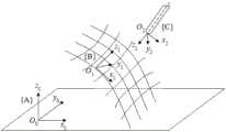
图1是本发明中电弧熔丝曲面增材位姿建模示意图。FIG. 1 is a schematic diagram of the pose modeling of the arc fuse curved surface additive in the present invention.
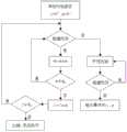
图2是本发明中焊枪自适应姿态控制方法流程图。Fig. 2 is a flow chart of the method for controlling the adaptive attitude of the welding torch in the present invention.
具体实施方式Detailed ways
以下结合附图说明和具体实施方式对本发明作进一步详细的说明。The present invention will be described in further detail below in conjunction with the description of the drawings and specific embodiments.
参见图1、图2,一种电弧熔丝曲面增材位姿建模方法,该建模方法包括以下步骤:Referring to Fig. 1 and Fig. 2, a method for modeling arc fuse curved surface additive pose, the modeling method includes the following steps:
S1、建立工件坐标系{A},该坐标系为笛卡尔坐标系O0x0y0z0;S1. Establish a workpiece coordinate system {A}, which is a Cartesian coordinate system O0 x0 y0 z0 ;
其中,O0x0y0面为水平平面,O0点的位置和O0x0、O0y0的方向按照工件定位进行确定,O0z0方向与重力方向相反,工件坐标系{A}满足右手定则条件;Among them, the O0 x0 y0 surface is a horizontal plane, the position of the O0 point and the directions of O0 x0 and O0 y0 are determined according to the workpiece positioning, and the O0 z0 direction is opposite to the direction of gravity, the workpiece coordinate system { A} satisfies the right-hand rule condition;
S2、建立焊道坐标系{B},该坐标系为笛卡尔坐标系O1x1y1z1;S2. Establish a welding bead coordinate system {B}, which is a Cartesian coordinate system O1 x1 y1 z1 ;
其中,O1点为空间曲面上当前堆焊点在工件坐标系{A}中的位置,即为焊道位置,O1z1方向为O1点在空间曲面上的法矢量方向,O1x1方向为O1点沿堆焊方向在空间曲面上的切向矢量方向,O1y1由右手定则确定;Among them, O1 point is the position of the current surfacing welding point on the space surface in the workpiece coordinate system {A}, that is, the position of the weld bead, O1 z1 direction is the normal vector direction of O1 point on the space surface, O1 The x1 direction is the tangential vector direction of the O1 point on the space surface along the surfacing direction, and O1 y1 is determined by the right-hand rule;
采用向量形式对焊道姿态进行建模:Model the weld bead pose in vector form:
Beadpos=sinβ*(0,1)+sinα*(1,0)=(sinα,sinβ)Beadpos=sinβ*(0,1)+sinα*(1,0)=(sinα,sinβ)
其中,焊道倾角α为O1x1与O0x0y0平面的夹角,当O1x1指向z0一侧时,α为正,当O1x1指向z0的反向时,α为负,α的角度范围为-90°~90°;焊道转角β为O0z0与O1x1z1平面的夹角,β的角度范围为0°~90°;向量Beadpos的第一项表示焊道倾角,第二项表示焊道转角;Among them, the bead inclination α is the angle between O1 x1 and O0 x0 y0 plane. When O1 x1 points to the side of z0 , α is positive, and when O1 x1 points to the opposite side of z0 When α is negative, the angle range of α is -90°~90°; the bead rotation angle β is the angle between O0 z0 and O1 x1 z1 plane, and the angle range of β is 0°~90°; The first item of the vector Beadpos represents the inclination angle of the weld bead, and the second item represents the angle of the weld bead;
S3、建立焊枪坐标系{C},该坐标系为笛卡尔坐标系O2x2y2z2;S3. Establish a welding gun coordinate system {C}, which is a Cartesian coordinate system O2 x2 y2 z2 ;
先建立焊枪初始坐标系O2x’2y’2z’2,其中,O2点为焊丝尖端的中心点,O2点与焊道位置O1点重合,O2x’2与O1x1同向,O2y’2、O2z’2分别与O1y1、O1z1反向,构成焊枪初始坐标系{C’},然后将焊枪初始坐标系{C’}分别绕x1、y1轴旋转,得到焊枪坐标系{C}-O2x2y2z2;First establish the initial coordinate system O2 x'2 y'2 z'2 of the welding torch, in which point O2 is the center point of the tip of the welding wire, point O2 coincides with point O1 of the welding bead position, and point O2 x'2 and O1 x1 is in the same direction, O2 y'2 , O2 z'2 are opposite to O1 y1 , O1 z1 respectively, forming the initial coordinate system {C'} of the welding gun, and then the initial coordinate system {C'} of the welding gun Rotate around the x1 and y1 axes respectively to obtain the welding gun coordinate system {C}-O2 x2 y2 z2 ;
焊枪姿态由焊枪侧偏角和焊枪行走角来确定:The attitude of the welding gun is determined by the side slip angle of the welding gun and the walking angle of the welding gun:
焊枪初始坐标系{C’}绕焊道坐标系{B}中x1轴旋转的角度γ为焊枪侧偏角,其中,对着x1O1方向顺时针旋转为正,逆时针旋转为负,γ的角度范围为-90°~90°;The angle γ rotated by the initial coordinate system {C'} of the welding torch around the x1 axis in the welding bead coordinate system {B} is the side slip angle of the welding torch, among which, the clockwise rotation against the x1 O1 direction is positive, and the counterclockwise rotation is negative , the angle range of γ is -90°~90°;
焊枪初始坐标系{C’}绕焊道坐标系{B}中y1轴旋转的角度

步骤S2中,焊道空间位姿由焊道坐标系{B}以及焊道倾角α和焊道转角β进行描述;对于空间中任意焊道姿态,都可分解为等坡平焊和立坡焊。In step S2, the spatial pose of the bead is described by the bead coordinate system {B}, the bead inclination α and the bead rotation angle β; for any bead pose in space, it can be decomposed into equal slope flat welding and vertical slope welding.
所述焊道坐标系{B}和工件坐标系{A}通过齐次坐标变换相互转化,焊道坐标系{B}在工件坐标系{A}中的焊道位姿矩阵

其中,列矢量

焊道倾角α和焊道转角β与列矢量

所述焊道坐标系{B}经旋转矩阵


焊枪位姿矩阵

一种电弧熔丝曲面增材位姿控制方法,所述控制方法包括采用曲面测地距离参考线偏移的焊道姿态控制方法及采用基于碰撞检测和平顺优化的焊枪自适应姿态控制方法;An arc fuse curved surface additive attitude control method, the control method includes a welding bead attitude control method using a surface geodesic distance reference line offset and a welding torch adaptive attitude control method based on collision detection and smoothing optimization;
曲面测地距离参考线偏移的焊道姿态控制方法包括以下步骤:The welding bead attitude control method for surface geodesic distance reference line offset includes the following steps:
对于曲面SA(x,y,z)=0,选取参考初始曲线F0,则其方程为:For the surface SA (x, y, z)=0, select the reference initial curve F0 , then its equation is:

计算曲线F0在当前位置点的法平面与曲面SA的交线

然后对交线


对前一道堆焊轨迹从起点到终点依次动态更新
基于碰撞检测和平顺优化的焊枪自适应姿态控制方法包括以下步骤:The adaptive attitude control method of welding torch based on collision detection and smooth optimization includes the following steps:
根据实际焊枪结构尺寸,采用直径等于焊枪最大直径的圆柱面模型来替代实际焊枪结构,圆柱面模型即为焊枪模型;According to the actual welding torch structure size, a cylindrical surface model with a diameter equal to the maximum diameter of the welding torch is used to replace the actual welding torch structure, and the cylindrical surface model is the welding torch model;
采用基于层次包围盒算法对焊枪模型与待增材工件进行碰撞检测,动态调整焊枪侧偏角γ和焊枪行走角

在满足未碰撞条件后,对焊枪轴线角变化率进行平顺优化处理,平顺优化处理后,再次进行碰撞检测,如此反复迭代,直到满足未碰撞条件,输出最终的焊枪侧偏角γ和焊枪行走角
所述碰撞检测过程中,优先调整焊枪行走角


本发明的原理说明如下:The principle of the present invention is described as follows:
本设计为实现电弧熔丝曲面增材的空间路径规划和制造工艺奠定技术基础,包括空间曲面焊道位置、焊道姿态和焊枪位置、焊枪姿态的描述与几何建模的电弧熔丝曲面增材位姿建模方法;以及采用曲面测地距离参考线偏移的焊道姿态控制方法和基于碰撞检测和平顺优化的焊枪自适应姿态控制方法。This design lays a technical foundation for realizing the spatial path planning and manufacturing process of arc fuse surface additive, including the spatial surface weld bead position, weld bead attitude and welding torch position, description of welding torch attitude and geometric modeling of arc fuse surface additive A pose modeling method; and a welding bead attitude control method using surface geodesic distance reference line offset and a welding torch adaptive attitude control method based on collision detection and smooth optimization.
通过建立工件坐标系、焊道坐标系和焊枪坐标系来描述空间曲面上焊道和焊枪位姿及其相互关系;焊道姿态由焊道坐标系下的焊道倾角和焊道转角进行建模描述,采用向量的表达形式建立空间曲面上电弧熔丝增材制造的广义焊道位姿统一模型,可以简单准确且唯一地描述空间位置上任意焊道姿态;焊枪位姿由焊枪坐标系和焊道坐标系的相互关系进行确定,采用焊枪侧偏角和焊枪行走角对焊枪姿态进行建模,焊枪侧偏角和焊枪行走角完整地确定了焊枪姿态信息;所建立的工件坐标系、焊道坐标系和焊枪坐标系可通过齐次坐标变换相互转化。By establishing the workpiece coordinate system, the welding bead coordinate system and the welding gun coordinate system, the position and the relationship between the welding bead and the welding gun on the space surface are described; Description, the generalized weld bead pose model for arc fuse additive manufacturing on the space surface is established in the form of vector expression, which can simply, accurately and uniquely describe any weld bead pose in space; the torch pose is determined by the welding torch coordinate system and the welding The mutual relationship of the track coordinate system is determined, and the welding torch attitude is modeled by the welding torch side slip angle and the welding torch walking angle. The welding torch side slip angle and the welding torch walking angle completely determine the welding torch attitude information; The coordinate system and the welding gun coordinate system can be transformed into each other through homogeneous coordinate transformation.
基于曲面测地距离参考线偏移的焊道姿态控制方法更能真实地代表曲面上路径之间的距离,保证堆焊轨迹可以均匀致密地依次填充待成形曲面,减少相邻焊道间的波动和缺陷;同时,空间多焊道的搭接宽度是焊道姿态参数的函数,可以实现自适应变距搭接,达到曲面上多道最优搭接的效果;基于层次包围盒算法的碰撞检测和平顺优化的焊枪自适应姿态控制方法可以根据空间增材位置和结构进行实时焊枪姿态调整,避免曲率变化大的位置焊枪行走角的突变,使机器人末端线速度平滑变化,执行更稳定。The welding bead attitude control method based on the offset of the surface geodesic distance reference line can more realistically represent the distance between the paths on the surface, ensure that the surfacing track can fill the surface to be formed evenly and densely, and reduce the fluctuation between adjacent weld beads and defects; at the same time, the overlap width of spatial multi-beads is a function of the attitude parameters of the weld bead, which can realize adaptive variable-distance overlap and achieve the effect of multi-pass optimal overlap on the surface; collision detection based on hierarchical bounding box algorithm The self-adaptive attitude control method of the welding torch optimized by peace and smooth can adjust the attitude of the welding torch in real time according to the position and structure of the additive in space, avoid the sudden change of the walking angle of the welding torch at the position with large curvature change, and make the linear speed of the robot end change smoothly and the execution is more stable.
建立的焊道和焊枪模型参数,可以相互转化计算,同时能完整地反映空间三维姿态,焊枪位姿信息可直接转化为机器人可识别代码,便于实现机器人电弧熔丝曲面增材制造的轨迹规划和姿态控制。The established welding bead and welding torch model parameters can be converted into each other for calculation, and at the same time can completely reflect the three-dimensional attitude of the space. The welding torch pose information can be directly converted into a robot identifiable code, which is convenient to realize the trajectory planning and the robot arc fuse surface additive manufacturing. Attitude control.
实施例:Example:
参见图1,一种电弧熔丝曲面增材位姿建模方法,该建模方法包括以下步骤:Referring to Fig. 1, a method for modeling an arc fuse curved surface additive pose, the modeling method includes the following steps:
S1、建立工件坐标系{A},该坐标系为笛卡尔坐标系O0x0y0z0;S1. Establish a workpiece coordinate system {A}, which is a Cartesian coordinate system O0 x0 y0 z0 ;
其中,O0x0y0面为水平平面,O0点的位置和O0x0、O0y0的方向按照工件定位最简原则(按照用户指定点和方向进行工件定位)进行确定,O0z0方向与重力方向相反,工件坐标系{A}满足右手定则条件;优选地,为了实际操作方便,O0x0、O0y0与机器人基坐标系方向保持一致,原点取工件上便于定位的特征点;Among them, the O0 x0 y0 surface is a horizontal plane, and the position of the O0 point and the directions of O0 x0 and O0 y0 are determined according to the principle of the simplest workpiece positioning (positioning the workpiece according to the point and direction specified by the user), The direction of O0 z0 is opposite to the direction of gravity, and the workpiece coordinate system {A} satisfies the condition of the right-hand rule; preferably, for the convenience of practical operation, O0 x0 and O0 y0 are consistent with the direction of the robot base coordinate system, and the origin is taken as Feature points on the workpiece that are easy to locate;
S2、建立焊道坐标系{B},该坐标系为笛卡尔坐标系O1x1y1z1;S2. Establish a welding bead coordinate system {B}, which is a Cartesian coordinate system O1 x1 y1 z1 ;
其中,O1点为空间曲面上当前堆焊点在工件坐标系{A}中的位置,即为焊道位置,O1z1方向为O1点在空间曲面上的法矢量方向,O1x1方向为O1点沿堆焊方向在空间曲面上的切向矢量方向,O1y1由右手定则确定;Among them, O1 point is the position of the current surfacing welding point on the space surface in the workpiece coordinate system {A}, that is, the position of the weld bead, O1 z1 direction is the normal vector direction of O1 point on the space surface, O1 The x1 direction is the tangential vector direction of the O1 point on the space surface along the surfacing direction, and O1 y1 is determined by the right-hand rule;
所述焊道坐标系{B}以及焊道倾角α和焊道转角β可以唯一准确地对焊道位姿进行描述,对于任意空间焊道姿态,可以看作是α和β的不同组合,采用向量形式对焊道姿态进行建模:The weld bead coordinate system {B}, as well as the weld bead inclination angle α and the weld bead rotation angle β can uniquely and accurately describe the weld bead pose. The pose of the weld bead is modeled in vector form:
Beadpos=sinβ*(0,1)+sinα*(1,0)=(sinα,sinβ)Beadpos=sinβ*(0,1)+sinα*(1,0)=(sinα,sinβ)
其中,焊道倾角α为O1x1与O0x0y0平面的夹角,当O1x1指向z0一侧时,α为正,当O1x1指向z0的反向时,α为负,α的角度范围为-90°~90°;焊道转角β为O0z0与O1x1z1平面的夹角,由于β的参考方向本身就包含z0,因此,其始终为正,β的角度范围为0°~90°,这与实际工程应用中刚好保持一致;向量Beadpos的第一项表示焊道倾角,第二项表示焊道转角,如表1所示,列出了几种常见的焊道姿态组合及其名称表示;对于空间中任意焊道姿态,都可分解为等坡平焊和立坡焊;Among them, the bead inclination α is the angle between O1 x1 and O0 x0 y0 plane. When O1 x1 points to the side of z0 , α is positive, and when O1 x1 points to the opposite side of z0 When α is negative, the angle of α ranges from -90° to 90°; the bead rotation angle β is the angle between O0 z0 and O1 x1 z1 plane, since the reference direction of β itself includes z0 , Therefore, it is always positive, and the angle of β ranges from 0° to 90°, which is consistent with practical engineering applications; the first item of the vector Beadpos represents the inclination angle of the weld bead, and the second item represents the angle of the weld bead, as shown in Table 1 As shown, several common weld bead attitude combinations and their names are listed; for any weld bead attitude in space, it can be decomposed into equal slope flat welding and vertical slope welding;
表1Table 1

所述焊道坐标系{B}和工件坐标系{A}通过齐次坐标变换相互转化,焊道坐标系{B}在工件坐标系{A}中的焊道位姿矩阵

其中,列矢量

焊道倾角α和焊道转角β与列矢量

S3、建立焊枪坐标系{C},该坐标系为笛卡尔坐标系O2x2y2z2;S3. Establish a welding gun coordinate system {C}, which is a Cartesian coordinate system O2 x2 y2 z2 ;
先建立焊枪初始坐标系O2x’2y’2z’2,其中,O2点为焊丝尖端的中心点,O2点与焊道位置O1点重合,O2x’2与O1x1同向,O2y’2、O2z’2分别与O1y1、O1z1反向,构成焊枪初始坐标系{C’},然后将焊枪初始坐标系{C’}分别绕x1、y1轴旋转,得到焊枪坐标系{C}-O2x2y2z2;First establish the initial coordinate system O2 x'2 y'2 z'2 of the welding torch, in which point O2 is the center point of the tip of the welding wire, point O2 coincides with point O1 of the welding bead position, and point O2 x'2 and O1 x1 is in the same direction, O2 y'2 , O2 z'2 are opposite to O1 y1 , O1 z1 respectively, forming the initial coordinate system {C'} of the welding gun, and then the initial coordinate system {C'} of the welding gun Rotate around the x1 and y1 axes respectively to obtain the welding gun coordinate system {C}-O2 x2 y2 z2 ;
焊枪姿态由焊枪侧偏角和焊枪行走角来确定:The attitude of the welding gun is determined by the side slip angle of the welding gun and the walking angle of the welding gun:
焊枪初始坐标系{C’}绕焊道坐标系{B}中x1轴旋转的角度γ为焊枪侧偏角,其中,对着x1O1方向顺时针旋转为正,逆时针旋转为负,γ的角度范围为-90°~90°;The angle γ rotated by the initial coordinate system {C'} of the welding torch around the x1 axis in the welding bead coordinate system {B} is the side slip angle of the welding torch, among which, the clockwise rotation against the x1 O1 direction is positive, and the counterclockwise rotation is negative , the angle range of γ is -90°~90°;
焊枪初始坐标系{C’}绕焊道坐标系{B}中y1轴旋转的角度

由于绕z1轴旋转在工程应用中无任何意义,因此,省去了焊枪绕自身旋转的自转角,γ和
所述焊道坐标系{B}经旋转矩阵


焊枪位姿矩阵

工件坐标系{A}为定坐标系,由用户根据工件特征进行自定义,焊道坐标系{B} 和焊枪坐标系{C}为动坐标系,确定了空间中焊道的轨迹和焊道/焊枪的姿态。The workpiece coordinate system {A} is a fixed coordinate system, which is customized by the user according to the characteristics of the workpiece. The welding bead coordinate system {B} and the welding gun coordinate system {C} are the moving coordinate systems, which determine the trajectory and the welding bead in the space. /The attitude of the torch.
一种电弧熔丝曲面增材位姿控制方法,所述控制方法包括采用曲面测地距离参考线偏移的焊道姿态控制方法及采用基于碰撞检测和平顺优化的焊枪自适应姿态控制方法;An arc fuse curved surface additive attitude control method, the control method includes a welding bead attitude control method using a surface geodesic distance reference line offset and a welding torch adaptive attitude control method based on collision detection and smoothing optimization;
曲面测地距离参考线偏移的焊道姿态控制方法包括以下步骤:The welding bead attitude control method for surface geodesic distance reference line offset includes the following steps:
对于曲面SA(x,y,z)=0,选取参考初始曲线F0,则其方程为:For the surface SA (x, y, z)=0, select the reference initial curve F0 , then its equation is:

其中,
计算曲线F0在当前位置点的法平面与曲面SA的交线

然后对交线


对前一道堆焊轨迹从起点到终点依次动态更新
基于碰撞检测和平顺优化的焊枪自适应姿态控制方法包括以下步骤:The adaptive attitude control method of welding torch based on collision detection and smooth optimization includes the following steps:
根据实际焊枪结构尺寸,采用直径等于焊枪最大直径的圆柱面模型来替代实际焊枪结构,圆柱面的母线长为L,圆柱面模型即为焊枪模型;According to the actual welding torch structure size, a cylindrical surface model with a diameter equal to the maximum diameter of the welding torch is used to replace the actual welding torch structure. The length of the busbar of the cylindrical surface is L, and the cylindrical surface model is the welding torch model;
参见图2,采用基于层次包围盒算法对焊枪模型与待增材工件进行碰撞检测,动态调整焊枪侧偏角γ和焊枪行走角


在满足未碰撞条件后,对焊枪轴线角变化率进行平顺优化处理(进一步微调焊枪姿态控制角γ和

所述碰撞检测过程中,优先调整焊枪行走角


Claims (6)
Translated fromChinese


Priority Applications (1)
| Application Number | Priority Date | Filing Date | Title |
|---|---|---|---|
| CN201911403303.7ACN111037054B (en) | 2019-12-31 | 2019-12-31 | A kind of arc fuse curved surface additive pose modeling method and control method |
Applications Claiming Priority (1)
| Application Number | Priority Date | Filing Date | Title |
|---|---|---|---|
| CN201911403303.7ACN111037054B (en) | 2019-12-31 | 2019-12-31 | A kind of arc fuse curved surface additive pose modeling method and control method |
Publications (2)
| Publication Number | Publication Date |
|---|---|
| CN111037054A CN111037054A (en) | 2020-04-21 |
| CN111037054Btrue CN111037054B (en) | 2020-10-09 |
Family
ID=70242152
Family Applications (1)
| Application Number | Title | Priority Date | Filing Date |
|---|---|---|---|
| CN201911403303.7AActiveCN111037054B (en) | 2019-12-31 | 2019-12-31 | A kind of arc fuse curved surface additive pose modeling method and control method |
Country Status (1)
| Country | Link |
|---|---|
| CN (1) | CN111037054B (en) |
Families Citing this family (6)
| Publication number | Priority date | Publication date | Assignee | Title |
|---|---|---|---|---|
| CN111702293A (en)* | 2020-06-10 | 2020-09-25 | 南京英尼格玛工业自动化技术有限公司 | A welding torch automatic trajectory avoidance method for high-speed rail corbel process holes |
| CN111922484B (en)* | 2020-06-30 | 2021-09-21 | 武汉理工大学 | Complex curved surface shape-following gradient additive remanufacturing method for hot forging die cavity |
| CN113496101B (en)* | 2021-06-28 | 2022-06-24 | 武汉理工大学 | A trajectory planning method for arc additive trajectory planning for global transverse welding of complex surfaces |
| CN115502996B (en)* | 2022-10-12 | 2025-08-05 | 上海交通大学 | Robotic welding trajectory planning method for lap joints of corrugated plates in LNG membrane tanks |
| CN116213892A (en)* | 2023-03-02 | 2023-06-06 | 东南大学 | Method for improving the stability of welding torch movement for robotic arc additive repair |
| CN116851871B (en)* | 2023-08-02 | 2024-10-11 | 湖北隆中实验室 | Robot roll forging die curved surface arc additive manufacturing method, equipment and medium |
Citations (9)
| Publication number | Priority date | Publication date | Assignee | Title |
|---|---|---|---|---|
| JPH0642943A (en)* | 1992-07-22 | 1994-02-18 | Ezel Inc | Method of measuring inclination angle of camera |
| CN102886592A (en)* | 2012-09-27 | 2013-01-23 | 清华大学 | Hyperbolic trace directional tangent constant-speed welding robot device |
| CN103418950A (en)* | 2013-07-03 | 2013-12-04 | 江南大学 | Automatic posture adjusting method for industrial welding robot in seam tracking process |
| CN105562973A (en)* | 2016-02-29 | 2016-05-11 | 华南理工大学 | Eight-axis robot space curve welding system and method for recognizing welding line by means of lasers |
| CN105643062A (en)* | 2016-04-08 | 2016-06-08 | 湘潭大学 | Rotating arc based method for recognizing complex curved surface shape and controlling welding gun pose |
| CN108332658A (en)* | 2018-01-25 | 2018-07-27 | 清华大学 | A kind of welding bead pose real-time detection method for complex-curved welding |
| CN109145453A (en)* | 2018-08-24 | 2019-01-04 | 西南交通大学 | Arc Additive Manufacturing Thermal Field Calculation Method for Complex Feature Structural Parts |
| CN109226937A (en)* | 2018-11-14 | 2019-01-18 | 南京工程学院 | Curve welding off-line programing method is mutually passed through in a kind of industrial robot space |
| CN110411338A (en)* | 2019-06-24 | 2019-11-05 | 武汉理工大学 | Three-dimensional scanning calibration method of welding torch tool parameters for robot arc additive repair |
- 2019
- 2019-12-31CNCN201911403303.7Apatent/CN111037054B/enactiveActive
Patent Citations (9)
| Publication number | Priority date | Publication date | Assignee | Title |
|---|---|---|---|---|
| JPH0642943A (en)* | 1992-07-22 | 1994-02-18 | Ezel Inc | Method of measuring inclination angle of camera |
| CN102886592A (en)* | 2012-09-27 | 2013-01-23 | 清华大学 | Hyperbolic trace directional tangent constant-speed welding robot device |
| CN103418950A (en)* | 2013-07-03 | 2013-12-04 | 江南大学 | Automatic posture adjusting method for industrial welding robot in seam tracking process |
| CN105562973A (en)* | 2016-02-29 | 2016-05-11 | 华南理工大学 | Eight-axis robot space curve welding system and method for recognizing welding line by means of lasers |
| CN105643062A (en)* | 2016-04-08 | 2016-06-08 | 湘潭大学 | Rotating arc based method for recognizing complex curved surface shape and controlling welding gun pose |
| CN108332658A (en)* | 2018-01-25 | 2018-07-27 | 清华大学 | A kind of welding bead pose real-time detection method for complex-curved welding |
| CN109145453A (en)* | 2018-08-24 | 2019-01-04 | 西南交通大学 | Arc Additive Manufacturing Thermal Field Calculation Method for Complex Feature Structural Parts |
| CN109226937A (en)* | 2018-11-14 | 2019-01-18 | 南京工程学院 | Curve welding off-line programing method is mutually passed through in a kind of industrial robot space |
| CN110411338A (en)* | 2019-06-24 | 2019-11-05 | 武汉理工大学 | Three-dimensional scanning calibration method of welding torch tool parameters for robot arc additive repair |
Non-Patent Citations (1)
| Title |
|---|
| 复杂空间轨迹焊接过程运动规划方法;曾锦乐;《清华大学学报》;20161031;第56卷(第10期);第1031-1036页* |
Also Published As
| Publication number | Publication date |
|---|---|
| CN111037054A (en) | 2020-04-21 |
Similar Documents
| Publication | Publication Date | Title |
|---|---|---|
| CN111037054B (en) | A kind of arc fuse curved surface additive pose modeling method and control method | |
| US9573224B2 (en) | System and method for determining beam power level along an additive deposition path | |
| CN112368099B (en) | Method and apparatus for manufacturing layered structure | |
| Ma et al. | Optimization strategies for robotic additive and subtractive manufacturing of large and high thin-walled aluminum structures | |
| CN114206617B (en) | Method for determining tool path for controlling printing tool | |
| US9757902B2 (en) | Additive layering method using improved build description | |
| JP6797324B1 (en) | Laminated modeling method | |
| Evjemo et al. | Additive manufacturing by robot manipulator: An overview of the state-of-the-art and proof-of-concept results | |
| CN105138000A (en) | Seven-freedom-degree space manipulator track planning method optimizing position and posture disturbance of pedestal | |
| Ma et al. | A path planning method for robotic wire and arc additive manufacturing of thin-walled structures with varying thickness | |
| CN106393106A (en) | Parameter adapting and calibrating robot NURBS curvilinear motion interpolation method | |
| CN111496428A (en) | Multilayer multi-pass welding bead planning method based on straight welding seam contour recognition and welding workstation | |
| Zhang et al. | A segmentation planning method based on the change rate of cross-sectional area of single V-groove for robotic multi-pass welding in intersecting pipe-pipe joint | |
| Dai et al. | Multiaxis wire and arc additive manufacturing for overhangs based on conical substrates | |
| Li et al. | Structured light-based visual servoing for robotic pipe welding pose optimization | |
| CN113199476B (en) | Planning algorithm of arc 8-shaped arc swinging path capable of quickly adjusting welding gun posture | |
| CN115007969A (en) | CMT + P arc additive manufacturing surface forming quality control method | |
| Wu et al. | Cold Spraying of 3D Parts–Challenges | |
| Liu et al. | A robot welding approach for the sphere-pipe joints with swing and multi-layer planning | |
| Wu et al. | 3D volume construction methodology for cold spray additive manufacturing | |
| Chen et al. | A novel 8-shape trajectory weaving welding control algorithm with auto-adjust welding torch attitude | |
| CN114896736A (en) | Anchor rod drill carriage drill arm positioning control method and system based on improved particle swarm optimization | |
| CN113996884A (en) | Arc fuse additive manufacturing method for curved hollow structural parts | |
| Bhatt et al. | Robot trajectory generation for multi-axis wire arc additive manufacturing | |
| JP7311481B2 (en) | Layered manufacturing method, layered manufacturing apparatus, and model display device |
Legal Events
| Date | Code | Title | Description |
|---|---|---|---|
| PB01 | Publication | ||
| PB01 | Publication | ||
| SE01 | Entry into force of request for substantive examination | ||
| SE01 | Entry into force of request for substantive examination | ||
| GR01 | Patent grant | ||
| GR01 | Patent grant |