CN111035408B - Method and system for enhanced visualization of ultrasound probe positioning feedback - Google Patents
Method and system for enhanced visualization of ultrasound probe positioning feedbackDownload PDFInfo
- Publication number
- CN111035408B CN111035408BCN201910972534.3ACN201910972534ACN111035408BCN 111035408 BCN111035408 BCN 111035408BCN 201910972534 ACN201910972534 ACN 201910972534ACN 111035408 BCN111035408 BCN 111035408B
- Authority
- CN
- China
- Prior art keywords
- reticle
- mask
- target area
- ultrasound image
- primary
- Prior art date
- Legal status (The legal status is an assumption and is not a legal conclusion. Google has not performed a legal analysis and makes no representation as to the accuracy of the status listed.)
- Active
Links
Images


Classifications
- A—HUMAN NECESSITIES
- A61—MEDICAL OR VETERINARY SCIENCE; HYGIENE
- A61B—DIAGNOSIS; SURGERY; IDENTIFICATION
- A61B8/00—Diagnosis using ultrasonic, sonic or infrasonic waves
- A61B8/46—Ultrasonic, sonic or infrasonic diagnostic devices with special arrangements for interfacing with the operator or the patient
- A61B8/461—Displaying means of special interest
- A61B8/463—Displaying means of special interest characterised by displaying multiple images or images and diagnostic data on one display
- A—HUMAN NECESSITIES
- A61—MEDICAL OR VETERINARY SCIENCE; HYGIENE
- A61B—DIAGNOSIS; SURGERY; IDENTIFICATION
- A61B8/00—Diagnosis using ultrasonic, sonic or infrasonic waves
- A61B8/46—Ultrasonic, sonic or infrasonic diagnostic devices with special arrangements for interfacing with the operator or the patient
- A61B8/461—Displaying means of special interest
- A—HUMAN NECESSITIES
- A61—MEDICAL OR VETERINARY SCIENCE; HYGIENE
- A61B—DIAGNOSIS; SURGERY; IDENTIFICATION
- A61B8/00—Diagnosis using ultrasonic, sonic or infrasonic waves
- A61B8/46—Ultrasonic, sonic or infrasonic diagnostic devices with special arrangements for interfacing with the operator or the patient
- A61B8/467—Ultrasonic, sonic or infrasonic diagnostic devices with special arrangements for interfacing with the operator or the patient characterised by special input means
- A—HUMAN NECESSITIES
- A61—MEDICAL OR VETERINARY SCIENCE; HYGIENE
- A61B—DIAGNOSIS; SURGERY; IDENTIFICATION
- A61B8/00—Diagnosis using ultrasonic, sonic or infrasonic waves
- A61B8/08—Clinical applications
- A—HUMAN NECESSITIES
- A61—MEDICAL OR VETERINARY SCIENCE; HYGIENE
- A61B—DIAGNOSIS; SURGERY; IDENTIFICATION
- A61B8/00—Diagnosis using ultrasonic, sonic or infrasonic waves
- A61B8/42—Details of probe positioning or probe attachment to the patient
- A—HUMAN NECESSITIES
- A61—MEDICAL OR VETERINARY SCIENCE; HYGIENE
- A61B—DIAGNOSIS; SURGERY; IDENTIFICATION
- A61B8/00—Diagnosis using ultrasonic, sonic or infrasonic waves
- A61B8/42—Details of probe positioning or probe attachment to the patient
- A61B8/4245—Details of probe positioning or probe attachment to the patient involving determining the position of the probe, e.g. with respect to an external reference frame or to the patient
- A61B8/4254—Details of probe positioning or probe attachment to the patient involving determining the position of the probe, e.g. with respect to an external reference frame or to the patient using sensors mounted on the probe
- A—HUMAN NECESSITIES
- A61—MEDICAL OR VETERINARY SCIENCE; HYGIENE
- A61B—DIAGNOSIS; SURGERY; IDENTIFICATION
- A61B8/00—Diagnosis using ultrasonic, sonic or infrasonic waves
- A61B8/46—Ultrasonic, sonic or infrasonic diagnostic devices with special arrangements for interfacing with the operator or the patient
- A61B8/467—Ultrasonic, sonic or infrasonic diagnostic devices with special arrangements for interfacing with the operator or the patient characterised by special input means
- A61B8/469—Ultrasonic, sonic or infrasonic diagnostic devices with special arrangements for interfacing with the operator or the patient characterised by special input means for selection of a region of interest
- A—HUMAN NECESSITIES
- A61—MEDICAL OR VETERINARY SCIENCE; HYGIENE
- A61B—DIAGNOSIS; SURGERY; IDENTIFICATION
- A61B8/00—Diagnosis using ultrasonic, sonic or infrasonic waves
- A61B8/52—Devices using data or image processing specially adapted for diagnosis using ultrasonic, sonic or infrasonic waves
- A61B8/5215—Devices using data or image processing specially adapted for diagnosis using ultrasonic, sonic or infrasonic waves involving processing of medical diagnostic data
- G—PHYSICS
- G06—COMPUTING OR CALCULATING; COUNTING
- G06T—IMAGE DATA PROCESSING OR GENERATION, IN GENERAL
- G06T7/00—Image analysis
- G06T7/0002—Inspection of images, e.g. flaw detection
- G06T7/0012—Biomedical image inspection
- G—PHYSICS
- G06—COMPUTING OR CALCULATING; COUNTING
- G06T—IMAGE DATA PROCESSING OR GENERATION, IN GENERAL
- G06T7/00—Image analysis
- G06T7/60—Analysis of geometric attributes
- G—PHYSICS
- G06—COMPUTING OR CALCULATING; COUNTING
- G06T—IMAGE DATA PROCESSING OR GENERATION, IN GENERAL
- G06T7/00—Image analysis
- G06T7/70—Determining position or orientation of objects or cameras
- G—PHYSICS
- G06—COMPUTING OR CALCULATING; COUNTING
- G06T—IMAGE DATA PROCESSING OR GENERATION, IN GENERAL
- G06T7/00—Image analysis
- G06T7/70—Determining position or orientation of objects or cameras
- G06T7/73—Determining position or orientation of objects or cameras using feature-based methods
- G—PHYSICS
- G06—COMPUTING OR CALCULATING; COUNTING
- G06T—IMAGE DATA PROCESSING OR GENERATION, IN GENERAL
- G06T2207/00—Indexing scheme for image analysis or image enhancement
- G06T2207/10—Image acquisition modality
- G06T2207/10132—Ultrasound image
- G—PHYSICS
- G06—COMPUTING OR CALCULATING; COUNTING
- G06T—IMAGE DATA PROCESSING OR GENERATION, IN GENERAL
- G06T2207/00—Indexing scheme for image analysis or image enhancement
- G06T2207/20—Special algorithmic details
- G06T2207/20081—Training; Learning
- G—PHYSICS
- G06—COMPUTING OR CALCULATING; COUNTING
- G06T—IMAGE DATA PROCESSING OR GENERATION, IN GENERAL
- G06T2207/00—Indexing scheme for image analysis or image enhancement
- G06T2207/20—Special algorithmic details
- G06T2207/20084—Artificial neural networks [ANN]
- G—PHYSICS
- G06—COMPUTING OR CALCULATING; COUNTING
- G06T—IMAGE DATA PROCESSING OR GENERATION, IN GENERAL
- G06T2207/00—Indexing scheme for image analysis or image enhancement
- G06T2207/20—Special algorithmic details
- G06T2207/20212—Image combination
- G06T2207/20221—Image fusion; Image merging
- G—PHYSICS
- G06—COMPUTING OR CALCULATING; COUNTING
- G06T—IMAGE DATA PROCESSING OR GENERATION, IN GENERAL
- G06T2207/00—Indexing scheme for image analysis or image enhancement
- G06T2207/30—Subject of image; Context of image processing
- G06T2207/30004—Biomedical image processing
Landscapes
- Health & Medical Sciences (AREA)
- Life Sciences & Earth Sciences (AREA)
- Engineering & Computer Science (AREA)
- Physics & Mathematics (AREA)
- Medical Informatics (AREA)
- General Health & Medical Sciences (AREA)
- Nuclear Medicine, Radiotherapy & Molecular Imaging (AREA)
- Radiology & Medical Imaging (AREA)
- Pathology (AREA)
- Public Health (AREA)
- Biomedical Technology (AREA)
- Molecular Biology (AREA)
- Surgery (AREA)
- Animal Behavior & Ethology (AREA)
- Biophysics (AREA)
- Heart & Thoracic Surgery (AREA)
- Veterinary Medicine (AREA)
- Computer Vision & Pattern Recognition (AREA)
- General Physics & Mathematics (AREA)
- Theoretical Computer Science (AREA)
- Quality & Reliability (AREA)
- Geometry (AREA)
- Ultra Sonic Daignosis Equipment (AREA)
Abstract
Translated fromChinese
Description
Translated fromChinese技术领域technical field
某些实施方案涉及超声成像。更具体地讲,某些实施方案涉及用于提供与超声探头的定位相关的视觉反馈以获得所期望的超声图像视图的方法和系统。视觉反馈可包括对应于超声探头的目标位置和取向的掩模以及对应于超声探头的当前位置和取向的标线。掩模和标线可叠加在超声数据上,其中标线位置和取向响应于超声探头的移动而动态地更新。超声操作者可基于反馈移动超声探头,直到标线与掩模对准。Certain embodiments relate to ultrasound imaging. More specifically, certain embodiments relate to methods and systems for providing visual feedback related to positioning of an ultrasound probe to obtain a desired view of an ultrasound image. The visual feedback may include a mask corresponding to the target position and orientation of the ultrasound probe and a reticle corresponding to the current position and orientation of the ultrasound probe. The mask and reticle can be superimposed on the ultrasound data, with the reticle position and orientation dynamically updated in response to movement of the ultrasound probe. Based on the feedback, the ultrasound operator can move the ultrasound probe until the reticle is aligned with the mask.
背景技术Background technique
超声成像是用于对人体中的器官和软组织进行成像的医学成像技术。超声成像使用实时的、非侵入性高频声波来产生二维(2D)图像和/或三维(3D)图像。Ultrasound imaging is a medical imaging technique used to image organs and soft tissues in the human body. Ultrasound imaging uses real-time, non-invasive high-frequency sound waves to generate two-dimensional (2D) images and/or three-dimensional (3D) images.
在超声成像检查期间,超声操作者可操纵超声探头以从不同的位置和取向扫描所关注的超声体积。例如,超声操作者可操纵探头以从多个不同的位置和取向获取胎儿心脏的图像。然而,正确定向探头以便从不同位置获取所期望体积的所关注的图像可能是有挑战性的,尤其是对于经验不足的操作者。患者的解剖结构可能看起来不同于各种透视图,并且存在用于调节探头的若干自由度(位置、旋转和倾斜)。从不同探头位置定位和扫描期望的所关注体积的困难可导致完成超声检查花费更长的总扫描时间,即使对于有经验的用户也是如此。During an ultrasound imaging exam, the ultrasound operator may maneuver the ultrasound probe to scan the ultrasound volume of interest from different positions and orientations. For example, an ultrasound operator may manipulate the probe to acquire images of the fetal heart from a number of different positions and orientations. However, properly orienting the probe to acquire images of the desired volume of interest from different locations can be challenging, especially for inexperienced operators. The patient's anatomy may look different from various perspectives, and there are several degrees of freedom (position, rotation and tilt) for adjusting the probe. Difficulties in locating and scanning the desired volume of interest from different probe positions can result in longer overall scan times to complete the ultrasound examination, even for experienced users.
通过将此类系统与本申请的其余部分中参考附图阐述的本公开的一些方面进行比较,常规和传统方法的进一步限制和缺点对本领域的技术人员将变得显而易见。Further limitations and disadvantages of conventional and conventional approaches will become apparent to those skilled in the art by comparing such systems with some aspects of the present disclosure set forth in the remainder of this application with reference to the accompanying drawings.
发明内容SUMMARY OF THE INVENTION
本发明公开了一种系统和/或方法,该系统和/或方法用于提供超声探头定位反馈的增强的可视化,基本上如结合附图中的至少一个所示和/或所述,如权利要求书中更完整地阐述。The present invention discloses a system and/or method for providing enhanced visualization of ultrasound probe positioning feedback, substantially as shown and/or described in connection with at least one of the accompanying drawings, as claimed More fully stated in the requirements book.
从以下描述和附图将更全面地理解本公开的这些和其他优点、方面和新颖特征、以及其例示的实施方案的细节。These and other advantages, aspects and novel features of the present disclosure, as well as the details of exemplified embodiments thereof, will be more fully understood from the following description and accompanying drawings.
附图说明Description of drawings
图1为根据各种实施方案的示例性超声系统的框图,该示例性超声系统能够操作以提供超声探头定位反馈的增强的可视化。1 is a block diagram of an exemplary ultrasound system operable to provide enhanced visualization of ultrasound probe positioning feedback, according to various embodiments.
图2示出了根据示例性实施方案的被配置为提供超声探头定位反馈的增强的可视化的示例性掩模和标线。2 illustrates an exemplary mask and reticle configured to provide enhanced visualization of ultrasound probe positioning feedback, according to an exemplary embodiment.
图3示出了根据各种实施方案的与对应于正确定位的超声探头的示例性掩模对准的示例性标线。3 illustrates an example reticle aligned with an example mask corresponding to a properly positioned ultrasound probe, according to various embodiments.
图4示出了根据示例性实施方案的示例性标线,该示例性标线与示例性掩模侧向不对准以提供用于将超声探头移动到正确位置和取向的反馈。4 illustrates an exemplary reticle laterally misaligned with an exemplary mask to provide feedback for moving the ultrasound probe to the correct position and orientation, according to an exemplary embodiment.
图5示出了根据各种实施方案的示例性标线,该示例性标线在高度方向上与示例性掩模对准以提供用于将超声探头移动到正确位置和取向的反馈。5 illustrates an exemplary reticle aligned in height with an exemplary mask to provide feedback for moving the ultrasound probe to the correct position and orientation, according to various embodiments.
图6示出了根据示例性实施方案的示例性标线,该示例性标线与示例性掩模旋转地不对准以提供用于将超声探头移动到正确位置和取向的反馈。6 illustrates an exemplary reticle rotationally misaligned with an exemplary mask to provide feedback for moving the ultrasound probe to the correct position and orientation, according to an exemplary embodiment.
图7示出了根据各种实施方案的具有侧向倾斜的示例性标线。FIG. 7 illustrates an exemplary reticle with a lateral slope in accordance with various embodiments.
图8示出了根据示例性实施方案的具有高度倾斜的示例性标线。FIG. 8 shows an exemplary reticle with a high slope according to an exemplary embodiment.
图9示出了根据各种实施方案的具有不同精度水平的示例性掩模。FIG. 9 illustrates exemplary masks with different levels of precision, according to various embodiments.
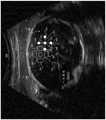
图10示出了根据示例性实施方案的覆盖在超声图像上以提供超声探头定位反馈的增强的可视化的示例性掩模和标线。10 illustrates an exemplary mask and reticle overlaid on an ultrasound image to provide enhanced visualization of ultrasound probe positioning feedback, according to an exemplary embodiment.
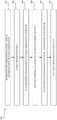
图11为示出根据各种实施方案的可用于提供超声探头定位反馈的增强的可视化的示例性步骤的流程图。11 is a flowchart illustrating exemplary steps that may be used to provide enhanced visualization of ultrasound probe positioning feedback, according to various embodiments.
具体实施方式Detailed ways
某些实施方案可见于用于定位超声探头的方法和系统中。各种实施方案具有提供用于定位探头以捕获期望的超声图像数据的视觉反馈的技术效果。此外,某些实施方案具有将超声探头的位置和取向转换成用于与单个掩模对准的单个标线的技术效果。单个掩模可提供限定适当位置、旋转、倾斜和与这些元素中的每一个相关联的精度量的目标区域。单个标线可提供元素以呈现相对于超声探头的当前位置、旋转和倾斜的视觉反馈。此外,各种实施方案具有如下技术效果:一旦在用于获得期望的超声图像数据的正确的位置和取向中检测到超声探头,就自动进行成像系统动作。例如,一旦对应于超声探头的位置和取向的标线与对应于所关注的体积的期望的视图的掩模对准,超声系统就可被配置为自动存储获取的超声图像数据,自动地提供用于进行测量的工具,以及/或者在获取的超声图像数据中自动执行解剖结构的测量,以及进行其他操作。Certain embodiments can be found in methods and systems for positioning ultrasound probes. Various embodiments have the technical effect of providing visual feedback for positioning the probe to capture the desired ultrasound image data. Furthermore, certain embodiments have the technical effect of converting the position and orientation of the ultrasound probe into a single reticle for alignment with a single mask. A single mask can provide a target area that defines the proper position, rotation, tilt, and amount of precision associated with each of these elements. A single reticle may provide elements to present visual feedback relative to the current position, rotation and tilt of the ultrasound probe. Furthermore, various embodiments have the technical effect of automatically performing imaging system actions once the ultrasound probe is detected in the correct position and orientation for obtaining the desired ultrasound image data. For example, once the reticle corresponding to the position and orientation of the ultrasound probe is aligned with the mask corresponding to the desired view of the volume of interest, the ultrasound system can be configured to automatically store acquired ultrasound image data, automatically provide tools for making measurements, and/or automatically performing measurements of anatomical structures in acquired ultrasound image data, among other operations.
当结合附图阅读时,将更好地理解前述发明内容、以及以下对某些实施方案的详述。就附图示出各种实施方案的功能块的图的范围而言,这些功能块不一定表示硬件电路之间的划分。因此,例如,一个或多个功能块(例如,处理器或存储器)可以在单件硬件(例如,通用信号处理器或随机存取存储器块、硬盘等)或多件硬件中实现。类似地,程序可以是独立程序,可以作为子例程包含在操作系统中,可以是安装的软件包中的功能等。应当理解,各种实施方案不限于附图中所示的布置和工具。还应理解,可以组合实施方案,或者可以利用其他实施方案,并且可以在不脱离各种实施方案的范围的情况下进行结构、逻辑和电气变化。因此,以下详述不应视为限制性意义,并且本公开的范围由所附权利要求书及其等同物限定。The foregoing summary, as well as the following detailed description of certain embodiments, will be better understood when read in conjunction with the accompanying drawings. To the extent that the figures illustrate diagrams of functional blocks of various embodiments, these functional blocks do not necessarily represent divisions between hardware circuits. Thus, for example, one or more functional blocks (eg, a processor or memory) may be implemented in a single piece of hardware (eg, a general purpose signal processor or random access memory block, hard disk, etc.) or in multiple pieces of hardware. Similarly, a program can be a stand-alone program, can be included in the operating system as a subroutine, can be a function in an installed software package, or the like. It should be understood that the various embodiments are not limited to the arrangements and instrumentality shown in the drawings. It is also to be understood that the embodiments may be combined, or other embodiments may be utilized, and structural, logical, and electrical changes may be made without departing from the scope of the various embodiments. Therefore, the following detailed description is not to be taken in a limiting sense, and the scope of the present disclosure is defined by the appended claims and their equivalents.
如本文所用,以单数形式列举并且以单词“一个”或“一种”开头的元件或步骤应当被理解为不排除多个所述元件或步骤,除非明确说明此类排除。此外,对“示例性实施方案”、“各种实施方案”、“某些实施方案”、“代表性实施方案”、“一个实施方案”等的引用并非旨在被解释为排除也包含所叙述的特征的其他实施方案的存在。此外,除非明确地相反说明,否则“包含”、“包括”或“具有”具有特定性质的一个元件或多个元件的实施方案可以包括不具有该性质的附加元件。As used herein, an element or step recited in the singular and beginning with the word "a" or "an" should be understood as not excluding a plurality of said elements or steps, unless such exclusion is expressly stated. Furthermore, references to "exemplary embodiments," "various embodiments," "certain embodiments," "representative embodiments," "one embodiment," etc. are not intended to be interpreted as excluding also inclusion of the recited Other embodiments of the features exist. Furthermore, unless expressly stated to the contrary, embodiments that "comprise," "include," or "have" an element or elements having a specified property may include additional elements that do not have that property.
另外,如本文所用,术语“图像”广义上是指可查看图像和表示可查看图像的数据。然而,许多实施方案生成(或被配置为生成)至少一个可查看图像。此外,如本文所用,短语“图像”用于指超声模式,诸如三维(3D)模式、B模式、CF模式和/或B模式和/或CF的子模式,诸如剪切波弹性成像(SWEI)、TVI、Angio、B流、BMI、BMI_Angio,并且在某些情况下还包括MM、CM、PW、TVD、CW,其中“图像”和/或“平面”包括单个或多个光束。Additionally, as used herein, the term "image" broadly refers to a viewable image and data representing a viewable image. However, many embodiments generate (or are configured to generate) at least one viewable image. Furthermore, as used herein, the phrase "image" is used to refer to an ultrasound mode, such as three-dimensional (3D) mode, B-mode, CF-mode and/or a sub-mode of B-mode and/or CF, such as shear wave elastography (SWEI) , TVI, Angio, B-stream, BMI, BMI_Angio, and in some cases MM, CM, PW, TVD, CW, where "image" and/or "plane" includes single or multiple beams.
此外,如本文所用,术语处理器或处理单元是指可执行各种实施方案所需的所需计算的任何类型的处理单元,诸如单核或多核:CPU、图形板、DSP、FPGA、ASIC或它们的组合。Furthermore, as used herein, the term processor or processing unit refers to any type of processing unit, such as single-core or multi-core, that can perform the desired computations required for various implementations: CPU, graphics board, DSP, FPGA, ASIC or their combination.
应当指出的是,本文所述的生成或形成图像的各种实施方案可包括用于形成图像的处理,该处理在一些实施方案中包括波束形成,并且在其他实施方案中不包括波束形成。例如,可在没有波束形成的情况下形成图像,诸如通过将解调数据的矩阵乘以系数矩阵,使得产品为图像,并且其中该过程不形成任何“光束”。另外,可使用可由多于一个传输事件产生的信道组合来执行图像的形成(例如,合成孔径技术)。It should be noted that various embodiments of generating or forming an image described herein may include processing for forming the image, which in some embodiments includes beamforming, and in other embodiments does not include beamforming. For example, an image can be formed without beamforming, such as by multiplying a matrix of demodulated data by a matrix of coefficients, so that the product is an image, and wherein the process does not form any "beams". Additionally, image formation may be performed using channel combinations that may result from more than one transmission event (eg, synthetic aperture techniques).
在各种实施方案中,进行超声处理以形成图像,例如,包括超声波束形成,诸如在软件、固件、硬件或它们的组合中接收波束形成。图1示出了具有根据各种实施方案形成的软件波束形成器架构的超声系统的一个具体实施。In various embodiments, sonication is performed to form the image, eg, including ultrasonic beamforming, such as receive beamforming in software, firmware, hardware, or a combination thereof. FIG. 1 illustrates one specific implementation of an ultrasound system with a software beamformer architecture formed in accordance with various embodiments.
图1为根据各种实施方案的示例性超声系统100的框图,该示例性超声系统能够操作以提供超声探头104定位反馈的增强的可视化。参见图1,其中示出了超声系统100。超声系统100包括发射器102、超声探头104、位置感测系统112、发射波束形成器110、接收器118、接收波束形成器120、RF处理器124、RF/IQ缓冲器126、用户输入模块130、信号处理器132、图像缓冲器136、显示系统134、存档138和教导引擎170。1 is a block diagram of an
发射器102可包括可操作以驱动超声探头104的合适逻辑、电路、接口和/或代码。超声探头104可包括二维(2D)压电元件阵列。超声探头104可包括通常构成相同元件的一组传输换能器元件106和一组接收换能器元件108。超声系统100可包括附接到探头104的位置感测系统112。位置感测系统112可包括光学跟踪系统、磁性位置系统、探头保持器中的传感器、运动感测系统和/或被配置为检测探头104的位置和取向的任何合适的系统或系统组合。例如,超声系统100可包括外部磁场发生器,该外部磁场发生器包括线圈和/或永磁体,该线圈和/或永磁体在通电时可产生静态外部磁场。位置感测系统112可被配置为检测预先存在的磁场或由外部磁场发生器产生的磁场。外部磁场发生器可被配置为产生具有梯度的磁场,使得可基于检测到的磁场来确定磁性位置传感器的位置。在各种实施方案中,位置感测系统112可将探头位置数据提供给超声系统100的信号处理器132,以与超声探头104在对应探头位置和取向处获取的超声图像数据相关联,以及/或者生成与探头位置和取向对应的标线300,如下文更详细地讨论。在某些实施方案中,超声探头104可操作以获取覆盖解剖结构诸如胎儿、胎儿心脏、肝脏、心脏或任何合适的器官或其他解剖结构的超声图像数据。
发射波束形成器110可包括合适的逻辑、电路、接口和/或代码,该逻辑、电路、接口和/或代码可操作以控制发射器102,该发射器通过发射子孔径波束形成器114驱动该组传输换能器元件106以将超声传输信号发射到所关注的区域(例如,人类、动物、地下腔体、物理结构等)中。所传输的超声信号可从所关注的对象如血细胞或组织中的结构向后散射,以产生回波。回波由接收换能器元件108接收。The transmit beamformer 110 may include suitable logic, circuits, interfaces and/or code operable to control the
超声探头104中的一组接收换能器元件108可操作以将接收的回波转换为模拟信号,通过接收子孔径波束形成器116进行子孔径波束形成,然后传送到接收器118。接收器118可包括合适的逻辑、电路、接口和/或代码,该逻辑、电路、接口和/或代码可操作以接收和解调来自接收子孔径波束形成器116的信号。解调的模拟信号可被传送至多个A/D转换器122中的一者或多者。A set of receive
多个A/D转换器122可包括合适的逻辑、电路、接口和/或代码,该逻辑、电路、接口和/或代码可用于将解调的模拟信号从接收器118转换为对应的数字信号。多个A/D转换器122设置在接收器118和接收波束形成器120之间。尽管如此,本公开在这方面并不受限制。因此,在一些实施方案中,多个A/D转换器122可被集成在接收器118内。The plurality of A/
接收波束形成器120可包括合适的逻辑、电路、接口和/或代码,该逻辑、电路、接口和/或代码可用于执行数字波束形成处理,以例如对从多个A/D转换器122接收的延迟信道信号进行求和并输出波束求和信号。所得经处理的信息可被转换回对应的RF信号。从接收波束形成器120输出的对应输出RF信号可被传送至RF处理器124。根据一些实施方案,接收器118、多个A/D转换器122和波束形成器120可被集成到单个波束形成器中,该波束形成器可以是数字波束形成器。The receive
RF处理器124可包括可操作以解调RF信号的合适逻辑、电路、接口和/或代码。根据一个实施方案,RF处理器124可包括复合解调器(未示出),该复合解调器可操作以解调RF信号以形成表示对应的回波信号的I/Q数据对。然后可将RF或I/Q信号数据传送至RF/IQ缓冲器126。RF/IQ缓冲器126可包括合适的逻辑、电路、接口和/或代码,该逻辑、电路、接口和/或代码可操作以提供由RF处理器124生成的RF或I/Q信号数据的临时存储。
用户输入模块130可用于患者数据、扫描参数、设置、选择协议和/或模板,识别超声图像数据中的解剖结构、执行测量等。在示例性实施方案中,用户输入模块130可操作以配置、管理和/或控制超声系统100中的一个或多个部件和/或模块的操作。就这一点而言,用户输入模块130可操作以配置、管理和/或控制发射器102、超声探头104、发射波束形成器110、位置感测系统112、接收器118、接收波束形成器120、RF处理器124、RF/IQ缓冲器126、用户输入模块130、信号处理器132、图像缓冲器136、显示系统134、存档138和/或教导引擎170。用户输入模块130可包括按钮、触摸屏、运动跟踪、语音识别、鼠标控制设备、键盘、相机和/或能够接收用户指令的任何其他设备。在某些实施方案中,例如,用户输入模块130中的一个或多个用户输入模块可以集成到其他部件(诸如显示系统134)中。例如,用户输入模块130可包括触摸屏显示器。在各种实施方案中,可响应于经由用户输入模块130接收的指令来选择超声图像数据中的解剖结构。在某些实施方案中,超声数据中的解剖结构的测量可响应于经由用户输入模块130接收的指令来执行,以例如选择特定测量、选择厚度开始和终点位置,以及/或者定义超声图像数据中的测量区域。User input module 130 may be used for patient data, scan parameters, settings, selecting protocols and/or templates, identifying anatomical structures in ultrasound image data, performing measurements, and the like. In an exemplary embodiment, the user input module 130 is operable to configure, manage and/or control the operation of one or more components and/or modules in the
信号处理器132可包括合适的逻辑、电路、接口和/或代码,该逻辑、电路、接口和/或代码可用于处理超声扫描数据(即,RF信号数据或IQ数据对)以生成用于在显示系统134上呈现的超声图像。信号处理器132可操作为对获取的超声扫描数据根据多个可选超声模态来执行一个或多个处理操作。在示例性实施方案中,信号处理器132可操作以执行混配、运动跟踪和/或散斑跟踪。随着接收到回波信号,可以在扫描会话期间实时处理获取的超声扫描数据。除此之外或另选地,超声扫描数据可以在扫描会话期间临时存储在RF/IQ缓冲器126中,并且在实时或离线操作中以不太实时的方式处理。在各种实施方案中,信号处理器132生成的超声图像中的每一个可与从超声探头104的探头位置感测系统112接收的探头位置数据相关联,以将超声图像中的每一个与超声图像数据获取时探头的位置和取向相关联。处理的图像数据和相关联的探头位置数据可呈现在显示系统134处和/或可存储在存档138处。存档138可为本地存档、图片存档和通信系统(PACS),或用于存储图像和相关信息的任何合适的设备。在示例性实施方案中,信号处理器132可包括掩模定位模块140、标线定位模块150和成像系统动作模块160。
超声系统100可操作为以适于所考虑的成像情况的帧速率连续获取超声扫描数据。典型帧速率在20至70的范围内,但可以更低或更高。所获取的超声扫描数据可以与帧速率相同或较慢或更快的显示速率显示在显示系统134上。将图像缓冲器136包括在内,用于存储未被安排立即显示的所获取的超声扫描数据的经过处理的帧。优选地,图像缓冲器136具有足够的容量来存储至少几分钟的超声扫描数据的帧。超声扫描数据的帧的存储方式便于根据其获取顺序或时间进行检索。图像缓冲区136可具体表现为任何已知的数据存储介质。The
信号处理器132可包括掩模定位模块140,该模块包括合适的逻辑、电路、接口和/或代码,该逻辑、电路、接口和/或代码可操作以接收对获取的超声图像数据中的解剖结构的识别和/或自动识别。例如,用户可通过经由用户输入模块130提供指令来手动识别获取的超声图像数据中的解剖结构。用户输入模块130可接收例如用户指令,以选择或以其他方式识别胎儿的超声图像数据中的头部、腹部或股骨以及其他部位。The
又如,掩模定位模块140可包括图像检测算法、一个或多个深度神经网络和/或可利用被配置为自动识别超声图像数据中的解剖结构的任何合适形式的图像检测技术或机器学习处理功能。例如,掩模定位模块140可由输入层、输出层以及输入层和输出层之间的一个或多个隐藏层组成。每个层可由多个可称为神经元的处理节点构成。例如,输入层可具有来自解剖结构的超声图像的每个像素或一组像素的神经元。输出层可具有对应于被成像的胎儿或器官的每个结构的神经元。例如,如果是对胎儿成像,则输出层可包括针对头部、腹部、股骨、未知部分和/或其他部分的神经元。每个层的每个神经元可执行处理功能并将经处理的超声图像信息传递至下游层的多个神经元中的一个以用于进一步处理。例如,第一层的神经元可学会识别超声图像数据中的结构的边缘。第二层的神经元可学会基于从第一层检测到的边缘识别形状。第三层的神经元可学习识别的形状相对于超声图像数据中的界标的位置。由掩模定位模块140深度神经网络执行的处理可以高概率识别超声图像数据中的解剖结构。As another example, the
在各种实施方案中,掩模定位模块140可包括合适的逻辑、电路、接口和/或代码,该逻辑、电路、接口和/或代码可操作以在获取的超声图像数据上基于解剖结构的识别生成并叠加掩模。该掩模可对应于特定解剖结构的预定义视图。例如,胎儿头部的预定义视图可以是丘脑水平处的头部的剖视图,其中具有两个半球的对称外观并且小脑不可视化。该视图可具有与中线回波成九十(90)度的正角。胎儿头部的预定义视图可提供期望的视图,以例如执行双顶径(BPD)测量和/或头部周长(HC)测量。又如,胎儿腹部的预定义视图可为胎儿腹部的横截面(尽可能为圆形),其中脐静脉处于门窦的水平,胃泡可视化,肾不可见。可将关于每个解剖结构的预定义视图的信息存储在存档138或任何合适的数据存储介质中。掩模定位模块140可访问与所识别的解剖结构的预定义视图相关的信息,并且可生成和叠加对应于获取的超声图像数据的预定义视图的掩模。In various embodiments,
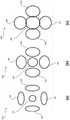
图9示出了根据各种实施方案的具有不同精度水平的示例性掩模200。参见图9,每个掩模200可包括主要目标区域202,至少一个侧向目标区域204和至少一个高度目标区域206。目标区域202、204、206中的每一个可为封闭的形状,诸如圆形、椭圆形、正方形、矩形或任何合适的形状。至少一个侧向目标区域204可位于主要目标区域202的第一侧面、第二侧面或两侧上。至少一个高度目标区域206可位于主要目标区域202的上方,位于主要目标区域202的下方,或位于主要目标区域202的上方和下方。在图9所示的示例性实施方案中,掩模包括居中定位的主要目标区域202,在主要目标区域202的两侧上具有侧向目标区域204,并且在主要目标区域202的上方和下方均具有高度目标区域206。目标区域202、204、206和掩模旋转指示器208的位置的对准(如图2至图6和图10所示)对应于用于获得解剖结构的预定义视图的超声探头104的目标取向(例如,旋转和倾斜)。掩模200相对于与超声探头104的当前位置相关联的标线300(示出于图2至图8和图10中)的位置的位置对应于用于获得解剖结构的预定义视图的超声探头104的目标位置。目标区域202、204、206的尺寸对应于用于获得解剖结构的预定义视图的对准精度的量。例如,较小的目标区域可对应于较高水平的对准精度以获得比较大的目标区域更高的预定义视图。如下文更详细地描述,操纵超声探头104以在掩模200的目标区域202、204、206内对准标线300导致超声探头104被定位和取向以获得解剖结构的期望的预定义视图。掩模200可覆盖在如图10所示并在下文更详细地描述的显示系统134处呈现的超声图像数据400上。附加地和/或另选地,掩模200可呈现在显示系统134处的超声显示器的其他部分处,诸如在显示器的侧面、顶部或底部面板中。FIG. 9 illustrates
再次参见图1,信号处理器132可包括标线定位模块150,该标线定位模块包括合适的逻辑、电路、接口和/或代码,该逻辑、电路、接口和/或代码可操作以在获取的超声图像数据400上生成并叠加对应于超声探头104相对于掩模200的当前位置和取向的标线300。例如,标线定位模块150可从位置感测系统112接收当前超声探头104的位置和取向,并且/或者可通过位置感测系统112访问与获取的超声图像数据相关联的位置数据。标线定位模块150可被配置为在超声探头104移动时基本上实时地动态地更新叠加到超声图像数据400上的标线300的位置和取向,以提供实时定位反馈,超声操作者可使用该实时定位反馈来移动探头104以使标线300与掩模200对准。标线300与掩模200的对准对应于超声探头104定位于适当的位置和取向,以获取解剖结构的期望的预定义视图。Referring again to FIG. 1, the
标线定位模块150可生成具有主要标线元件302、至少一个侧向标线元件304、至少一个高度标线元件306和标线旋转指示器308的标线300。标线元件302、304、306中的每一个可具有一种形状,诸如圆形、椭圆形、正方形、矩形、星形或任何合适的形状。标线元件302、304、306可具有与掩模200的目标区域202、204、206相同的尺寸或更小的尺寸。至少一个侧向标线元件304可位于主要标线元件302的第一侧面、第二侧面或两侧上。至少一个高度标线元件306可位于主要标线元件302的上方,位于主要标线元件302的下方,或位于主要标线元件302的上方和下方。在代表性实施方案中,侧向和高度标线元件304、306的数量可对应于掩模200的侧向和高度目标区域204、206的数量。标线旋转指示器308可与主要标线元件302成一角度延伸到侧向标线元件304和高度标线元件306之间。在各种实施方案中,标线旋转指示器308不居中(即,45度)在侧向标线元件304和高度标线元件306之间,使得标线300与掩模200的对准在仅一个超声探头104取向中是可能的。The reticle positioning module 150 may generate a
在图2至图8和图10所示的示例性实施方案中,标线300包括居中定位的主要标线元件302,在主要标线元件302的两侧上具有侧向标线元件304,并且在主要标线元件302上方和下方均具有高度标线元件306。在主要标线元件302的两侧上具有侧向标线元件304的某些实施方案中,侧向标线元件304可通过侧向连接元件310连接。在具有位于主要标线元件302上方和下方的高度标线元件306的各种实施方案中,可通过高度连接元件312来连接高度标线元件306。侧向和高度连接元件310、312连同主要标线元件302可提供对应的超声探头104的倾斜的增强的可视化。例如,如图7和图8所示,主要标线元件302可在侧向和高度连接元件310、312相交的点的上方、下方、左侧或右侧示出。主要标线元件302相对于侧向和高度连接元件310、312的相交点的位置可提供相对于超声探头104的当前倾斜的量和方向的视觉反馈。例如,主要标线元件302相对于图7中的侧向和高度连接元件310、312的相交点的位置指示超声探头104当前侧向向右侧倾斜。又如,主要标线元件302相对于图8中的侧向和高度连接元件310、312的相交点的位置指示超声探头104当前在向前的高度方向上倾斜。In the exemplary embodiment shown in FIGS. 2-8 and 10, the
在图2至图8和图10所示的示例性实施方案中,标线300包括与相关联的超声探头104的旋转取向对应的标线旋转指示器308。标线元件302、304、306和标线旋转指示器308的位置的对准提供与超声探头104的当前取向(例如,旋转和倾斜)相关的视觉反馈,使得超声探头104可由操作者操纵以匹配掩模200的目标区域202、204、206和掩模旋转指示器208的取向。标线300相对于掩模200的位置和取向的位置和取向提供了用于移动超声探头104以匹配掩模200的目标区域202、240、206的视觉反馈。如下文更详细地描述,操纵超声探头104以将标线300的标线元件302、304、306、308与掩模200的目标区域202、204、206和旋转指示器208对准,导致超声探头104被定位和取向以获得解剖结构的期望的预定义视图。标线300可与掩模200覆盖到呈现在显示系统134处的超声图像数据400上,如图10所示并在下文更详细地描述。附加地和/或另选地,标线300和掩模200可呈现在显示系统134处的超声显示器的其他部分处,诸如在显示器的侧面、顶部或底部面板中。In the exemplary embodiment shown in FIGS. 2-8 and 10 , the
图2示出了根据示例性实施方案的被配置为提供超声探头104定位反馈的增强的可视化的示例性掩模200和标线300。图3示出了根据各种实施方案的与对应于正确定位的超声探头104的示例性掩模200对准的示例性标线300。图4示出了根据示例性实施方案的示例性标线300,该示例性标线与示例性掩模200侧向不对准以提供用于将超声探头104移动到正确位置和取向的反馈。图5示出了根据各种实施方案的示例性标线300,该示例性标线在高度方向上与示例性掩模200不对准以提供用于将超声探头104移动到正确位置和取向的反馈。图6示出了根据示例性实施方案的示例性标线300,该示例性标线与示例性掩模200旋转地不对准以提供用于将超声探头104移动到正确位置和取向的反馈。FIG. 2 illustrates an
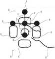
参见图2至图6,掩模200包括主要目标区域202,在主要目标区域202两侧上的侧向目标区域204,在主要目标区域202上方和下方的高度目标区域206,以及掩模旋转指示器208。目标区域202、204、206中的每一个可为封闭的形状,诸如圆形、椭圆形、正方形、矩形或任何合适的形状。掩模旋转指示器208可与主要目标区域202成一角度延伸。例如,掩模旋转指示器208可在侧向目标区域204和高度目标区域206之间延伸。在各种实施方案中,旋转指示器208在侧向目标区域204和高度目标区域206之间不居中(即,45度),使得标线300与掩模200的对准在仅一个超声探头104取向中是可能的。在各种实施方案中,掩模可具有非军事和非技术外观。例如,掩模200可具有类似于植物或花的外观,诸如四叶草等,其中侧向目标区域204和高度目标区域206类似于叶子或叶片,并且掩模旋转指示器208类似于茎部。目标区域202、204、206和掩模旋转指示器208的位置的对准对应于用于获得解剖结构的预定义视图的超声探头104的目标取向(例如,旋转和倾斜)。掩模200相对于与超声探头104的当前位置相关联的标线300的位置的位置对应于用于获得解剖结构的预定义视图的超声探头104的目标位置。2-6,
标线300包括主要标线元件302、主要标线元件302两侧上的侧向标线元件304、主要标线元件302上方和下方的高度标线元件306,以及标线旋转指示器308。侧向标线元件304可通过侧向连接元件310连接。高度标线元件306可通过高度连接元件312连接。标线旋转指示器308对应于相关联的超声探头104的旋转取向。标线旋转指示器308可与主要标线元件302成一角度延伸。例如,标线旋转指示器308可在侧向标线元件304和高度标线元件306之间延伸。在各种实施方案中,标线旋转指示器308不居中(即,45度)在侧向标线元件304和高度标线元件306之间,使得标线300与掩模200的对准在仅一个超声探头104取向中是可能的。The
参见图3,标线300被示出为与掩模200对准。例如,主要标线元件302被定位并取向在掩模200的封闭的主要目标区域202内。侧向标线元件304中的每一个被定位在掩模200的相应封闭的侧向目标区域204内。高度标线元件306中的每一个被定位在掩模200的相应封闭的高度目标区域206内。标线旋转指示器308沿相同的方向延伸并且可与掩模旋转指示器208重叠。Referring to FIG. 3 ,
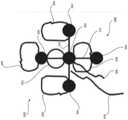
参见图4,标线300被示出为与掩模200侧向不对准。例如,主要标线元件302、侧向标线元件304、高度标线元件306和标线旋转指示器308侧向定位于掩模200的对应的主要目标区域202、侧向目标区域204、高度目标区域206和掩模旋转指示器208的右侧。标线200相对于掩模300的位置提供视觉反馈,引导超声操作者将超声探头104向左移动,以使标线300与掩模200对准。Referring to FIG. 4 ,
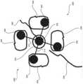
参见图5,标线300被示出为在高度方向上与掩模200不对准。例如,主要标线元件302、侧向标线元件304、高度标线元件306和标线旋转指示器308定位于掩模200的对应的主要目标区域202、侧向目标区域204、高度目标区域206和掩模旋转指示器208的下方。标线200相对于掩模300的位置和取向提供视觉反馈,引导超声操作者将超声探头104在高度方向向前移动,以使标线300与掩模200对准。Referring to FIG. 5 , the
参见图6,标线300被示出为与掩模200旋转地不对准。例如,主要标线元件302、侧向标线元件304、高度标线元件306和标线旋转指示器308被取向成与掩模200的对应的主要目标区域202、侧向目标区域204、高度目标区域206和掩模旋转指示器208成约一百八十(180)度。例如,标线旋转指示器308在与掩模旋转指示器208相反的方向上延伸。标线200相对于掩模300的取向提供视觉反馈,引导超声操作者将超声探头104旋转约180度,以使标线300与掩模200对准。Referring to FIG. 6 , the
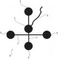
图7示出了根据各种实施方案的具有侧向倾斜的示例性标线300。图8示出了根据示例性实施方案的具有高度倾斜的示例性标线300。参见图7和图8,标线300包括主要标线元件302、主要标线元件302两侧上的侧向标线元件304、主要标线元件302上方和下方的高度标线元件306,以及标线旋转指示器308。侧向标线元件304通过侧向连接元件310连接。高度标线元件306通过高度连接元件312连接。侧向和高度连接元件310、312相交。侧向和高度连接元件310、312之间的相交处相对于主要标线元件302的位置提供了关于相关联的超声探头的倾斜的反馈。例如,主要标线元件302可在侧向和高度连接元件310、312相交的点的上方、下方、左侧、右侧或相交的点处示出。未倾斜的超声探头104可具有定位在侧向和高度连接元件310、312相交的点处的主要标线元件302,如图2至图6和图10所述。如果主要标线元件302定位在交叉点右侧的侧向连接元件310上,则超声探头104侧向向右倾斜,如图7所示。如果主要标线元件302定位在交叉点左侧的侧向连接元件310上,则超声探头104侧向向左倾斜。如果主要标线元件302定位在相交点上方的高度连接元件312上,则超声探头104在高度方向上向前倾斜,如图8所示。如果主要标线元件302定位在相交点下方的高度连接元件312上,则超声探头104在高度方向上向后倾斜。因此,主要标线元件302相对于侧向和高度连接元件310、312的相交点的位置可提供相对于超声探头104的当前倾斜的量和方向的视觉反馈。FIG. 7 illustrates an
图10示出了根据示例性实施方案的覆盖在超声图像400上以提供超声探头104定位反馈的增强的可视化的示例性掩模200和标线300。参见图10,将掩模200、标线300和图像标签402叠加在超声图像400上。具有覆盖的掩模200、标线300和标签400的超声图像400可呈现在显示系统134处。掩模200包括主要目标区域202、侧向目标区域204、高度目标区域206和掩模旋转指示器208。掩模200对应于用于获取所识别的解剖结构的预定义视图的超声图像数据400的目标超声探头104的位置和取向。标线300包括主要标线元件302、侧向标线元件304、高度标线元件306和标线旋转指示器308。侧向标线元件304通过侧向连接元件310连接。高度标线元件306通过高度连接元件312连接。标线300对应于当前超声探头104的位置和取向。图像标签402对应于与掩模200相关联的解剖结构的预定义视图。例如,预定义视图可对应于双顶径(BPD)测量,如图10所示。图10所示的标线300看起来在取向(例如,倾斜和旋转)上对准,但在位置(例如,侧向和高度)上不对准。例如,超声操作者可向前和向左移动超声探头104,以使标线300与掩模200对准。当超声探头被移动、旋转和/或倾斜时,标线300的位置和取向在显示系统134处的超声图像400上基本上实时地动态地更新。超声图像数据400在由超声探头104获取时动态地呈现在显示系统134处。在显示系统134处呈现的超声数据400是当标线300与掩模200对准时的解剖结构的预定义视图。10 illustrates an
再次参见图1,信号处理器132可包括成像系统动作模块160,该成像系统动作模块包括合适的逻辑、电路、接口和/或代码,该逻辑、电路、接口和/或代码可操作以响应于标线300与掩模200的对准而执行成像系统动作。例如,成像系统动作模块160可被配置为当标线300与掩模200对准时自动存储获取的超声图像数据400。获取的超声图像数据400可存储在存档138或任何合适的数据存储介质中。又如,成像系统动作模块160可被配置为在标线300与掩模200匹配时自动提供测量工具。该测量工具可包括厚度工具、结构轮廓工具或任何合适的测量工具。例如,可执行厚度工具以经由用户输入模块130来接收厚度测量的开始点和终点选择。可执行结构轮廓工具以经由用户输入模块130接收用户指令,以在超声图像数据400中显示所选择的解剖结构的轮廓,以用于执行区域测量或任何合适的测量。在各种实施方案中,成像系统动作模块160可被配置为自动执行对应于解剖结构的预定义视图的一个或多个测量。例如,如果预先限定的视图是胎儿头部的视图,则成像系统动作模块160可自动执行双顶径(BPD)或头部周长(HC)测量。又如,如果预定义视图是胎儿腹部的视图,则成像系统动作模块160可自动执行腹围(AC)测量。如果预定义视图是胎儿股骨的视图,则成像系统动作模块160可自动执行股骨骨干长度(FDL)测量。自动执行的或经由测量工具执行的测量可由成像系统动作模块160存储在存档138中或任何合适的数据存储介质中。Referring again to FIG. 1 , the
仍然参见图1,教导引擎170可包括合适的逻辑、电路、接口和/或代码,该逻辑、电路、接口和/或代码可操作以训练掩模定位模块140的深度神经网络的神经元以自动识别解剖结构。例如,教导引擎170可使用分类图像的数据库来训练掩模定位模块140的深度神经网络。例如,掩模定位模块140深度神经网络可由教导引擎170利用特定解剖结构的图像进行训练,以相对于特定解剖结构的特性来训练掩模定位模块140,该特性为诸如结构边缘的外观、基于边缘的结构形状的外观、相对于超声图像数据400中的界标的形状的位置等。在某些实施方案中,解剖结构可为胎儿,并且结构信息可包括关于胎儿头部、腹部、股骨等的边缘,形状和位置的信息。在各种实施方案中,训练图像的数据库可存储在存档138或任何合适的数据存储介质中。在某些实施方案中,训练引擎170和/或训练图像数据库可以是经由有线或无线连接通信地耦接到超声系统100的外部系统。Still referring to FIG. 1 , the
图11为示出根据各种实施方案的可用于提供超声探头104定位反馈的增强的可视化的示例性步骤502至512的流程图500。参见图11,其中示出了包括示例性步骤502至512的流程图500。某些实施方案可省略步骤中的一个或多个,以及/或者以与所列顺序不同的顺序执行步骤,以及/或者组合下文讨论的某些步骤。例如,在某些实施方案中,一些步骤可能不被执行。又如,某些步骤可以与下面所列的不同的时间顺序(包括同时)执行。11 is a
在步骤502处,超声系统100可获取解剖结构的超声图像数据400和探头位置数据,该探头位置数据指定超声探头104相对于获取的超声图像数据400的位置和取向。例如,超声系统100可使用具有位置感测系统112的超声探头104获取超声图像数据400。超声探头104可提供与解剖结构诸如胎儿或任何合适的解剖结构相对应的超声图像数据。位置感测系统112可提供被提供给超声系统100的信号处理器132的探头位置数据。信号处理器132可将探头位置数据与在超声探头104的每一个位置和取向处获取的对应超声图像数据400相关联。At
在步骤504处,超声系统100的信号处理器132可识别和/或接收超声图像数据400中的解剖结构的识别。例如,信号处理器132的掩模定位模块140可在超声操作者获取超声图像数据期间经由用户输入模块130接收识别。又如,信号处理器132的掩模定位模块140可采用图像检测和/或机器学习算法来识别超声图像数据400中的解剖结构。在各种实施方案中,掩模定位模块140的图像检测和/或机器学习算法可包括由输入层、输出层以及输入层和输出层之间的一个或多个隐藏层组成的深度神经网络。这些层中的每一层可在将经处理的超声信息传递至后续层以用于进一步处理之前执行处理功能。由掩模定位模块140深度神经网络执行的处理可识别超声图像数据400中的解剖结构。解剖结构可以是器官,诸如肝脏、心脏等。解剖结构可以是胎儿,并且可以包括胎体结构,诸如胎儿头部、胎儿腹部、胎儿股骨和/或胎儿的任何合适的结构。At
在步骤506处,信号处理器132可基于在步骤504处对解剖结构的识别来生成和覆盖对应于获取的超声图像数据400上的预定义视图的掩模200。例如,各种解剖结构可与预定义视图相关联,从而提供每个解剖结构的期望视图。可将关于每个解剖结构的预定义视图的信息存储在存档138或任何合适的数据存储介质中。信号处理器132的掩模定位模块140可访问与所识别的解剖结构的预定义视图相关的信息,并且可在超声图像数据400上生成并叠加掩模200以提供超声探头104的目标位置和取向。掩模200可包括主要目标区域202、至少一个侧向目标区域204、至少一个高度目标区域206和掩模旋转指示器208。目标区域202、204、206中的每一个可为封闭的形状,诸如圆形、椭圆形、正方形、矩形或任何合适的形状。目标区域202、204、206的尺寸可对应于用于获得解剖结构的预定义视图的对准精度的量。至少一个侧向目标区域204可位于主要目标区域202的第一侧面、第二侧面或两侧上。至少一个高度目标区域206可位于主要目标区域202的上方,位于主要目标区域202的下方,或位于主要目标区域202的上方和下方。掩模旋转指示器208可与主要目标区域202成一角度在侧向目标区域204和高度目标区域206之间延伸。目标区域202、204、206和掩模旋转指示器208的位置的对准可对应于用于获得解剖结构的预定义视图的超声探头104的目标旋转和倾斜。掩模200的位置和取向可对应于用于获得解剖结构的预定义视图的超声探头104的目标位置和取向。At
在步骤508处,信号处理器132可在获取的超声图像数据400上生成并覆盖对应于探头104相对于掩模200的当前位置和取向的标线300。例如,标线定位模块150可生成具有主要标线元件302、至少一个侧向标线元件304、至少一个高度标线元件306和标线旋转指示器308的标线300。标线元件302、304、306中的每一个可具有一种形状,诸如圆形、椭圆形、正方形、矩形、星形或任何合适的形状。标线元件302、304、306可具有与掩模200的目标区域202、204、206相同的尺寸或更小的尺寸。至少一个侧向标线元件304可位于主要标线元件302的第一侧面、第二侧面或两侧上。至少一个高度标线元件306可位于主要标线元件302的上方,位于主要标线元件302的下方,或位于主要标线元件302的上方和下方。侧向和高度标线元件304、306的数量对应于掩模200的侧向和高度目标区域204、206的数量。标线旋转指示器308可与主要标线元件302成一角度延伸到侧向标线元件304和高度标线元件306之间。信号处理器132的标线定位模块150可从位置感测系统112接收当前超声探头104的位置和取向,并且/或者可通过位置感测系统112访问与获取的超声图像数据相关联的位置和取向数据。标线定位模块150基于位置和取向数据将所生成的标线300相对于掩模200叠加在超声图像数据400上。At
在步骤510处,信号处理器132可基于探头104的移动动态地更新标线300相对于掩模200的位置和取向,直到标线300移动到与掩模200匹配的位置和取向。例如,信号处理器132的标线定位模块150可在超声探头104移动、旋转和/或倾斜时基本上实时动态地更新叠加到超声图像数据400上的标线300的位置和取向,以提供实时定位反馈,超声操作者可使用该实时定位反馈来移动探头104以使标线300与掩模200对准。标线300与掩模200的对准对应于超声探头104定位于适当的位置和取向,以获取解剖结构的期望的预定义视图。At
在步骤512处,信号处理器132可响应于标线300与掩模200的对准而执行成像系统动作。例如,信号处理器132的成像系统动作模块160可被配置为自动存储预定义视图的获取的超声图像数据400,自动提供用于执行预定义视图的获取的超声图像数据400的测量的测量工具,并且/或者自动执行预定义视图的获取的超声图像数据400的测量。超声图像数据和/或测量可由成像系统动作模块160存储在存档138中或任何合适的数据存储介质中。At
本公开的各方面提供了用于提供超声探头104定位反馈的增强的可视化的方法500和系统100。根据各种实施方案,方法500可包括通过至少一个处理器132、140、150、160接收502超声图像数据400和与超声图像数据400对应的探头位置数据。方法500可包括由至少一个处理器132、140在显示系统134处呈现506掩模200,该掩模限定对应于解剖结构的预定义超声图像视图的超声探头104的目标位置和取向。掩模200可包括主要目标区域202、相对于主要目标区域202侧向定位的至少一个侧向目标区域204,以及相对于主要目标区域202在高度方向定位的至少一个高度目标区域206。方法500可包括通过至少一个处理器132、150在显示系统134处呈现508、510标线300,该标线具有基于探头位置数据的与超声探头104的位置和取向相对应的标线位置和取向。显示系统134处呈现的标线位置和取向基于探头位置数据并响应于超声探头104的移动而相对于掩模200动态地更新。标线300可包括主要标线元件302,当超声探头104位于目标位置和取向时,该主要标线元件被配置成与掩模200的主要目标区域202对准。标线300可包括至少一个侧向标线元件304,该侧向标线元件相对于主要标线元件302侧向定位并且被配置为当超声探头104位于目标位置和取向时与掩模200的至少一个侧向目标区域204对准。标线300可包括至少一个高度标线元件306,该至少一个高度标线元件相对于主要标线元件302在高度方向定位并且被配置为当超声探头104定位于目标位置和取向时与掩模200的至少一个高度目标区域206对准。方法500可包括响应于超声探头104移动到目标位置和取向以用于获取解剖结构的预定义超声图像视图的超声图像数据400,基于与掩模200对准的标线300,通过至少一个处理器132、160执行512成像系统动作。Aspects of the present disclosure provide a
在代表性实施方案中,方法500可包括识别504超声图像数据400中的解剖结构。解剖结构的预定义超声图像视图可基于超声图像数据400中识别的解剖结构。在示例性实施方案中,可由处理器132、140基于机器学习算法自动识别解剖结构。在各种实施方案中,掩模200和标线300叠加在超声图像数据400上。在某些实施方案中,超声图像数据400和与超声图像数据400对应的探头位置数据可由具有位置感测系统112的超声探头104获取。在代表性实施方案中,掩模200可包括掩模旋转指示器208,该掩模旋转指示器与主要目标区域202成一角度在至少一个侧向目标区域204中的一个与至少一个高度目标区域206中的一个之间延伸。标线300可包括与主要标线元件302成一角度在至少一个侧向标线元件304中的一个和至少一个高度标线元件206中的一个之间延伸的标线旋转指示器308。标线旋转指示器308可被配置为当超声探头104定位于目标位置和取向时,与掩模旋转指示器208对准。In a representative embodiment,
在示例性实施方案中,至少一个侧向目标区域204可为在主要目标区域202的每个侧面上的一个侧向目标区域204。至少一个高度目标区域206可为在主要目标区域202的每个高度方向上的一个高度目标区域206。至少一个侧向标线元件304可为在主要标线元件302的每个侧面上的一个侧向标线元件304。至少一个高度标线元件306可为在主要标线元件302的每个高度方向上的一个高度标线元件306。在某些实施方案中,成像系统动作可以是自动存储解剖结构的预定义超声图像视图的超声图像数据400。成像系统动作可自动地提供用于在解剖结构的预定义超声图像视图的超声图像数据400内执行测量的测量工具。成像系统动作可以是在解剖结构的预定义超声图像视图的超声图像数据400内自动执行测量。In an exemplary embodiment, the at least one
各种实施方案提供了用于提供超声探头104定位反馈的增强的可视化的系统100。系统100可包括超声探头104、显示系统134和至少一个处理器132、140、150、160。至少一个处理器132、140、150、160可被配置为接收超声图像数据400和与超声图像数据400对应的探头位置数据。至少一个处理器132、140可被配置为在显示系统134处呈现限定超声探头104的目标位置和取向的掩模200,该目标位置和取向对应于解剖结构的预定义超声图像视图。掩模200可包括主要目标区域202、相对于主要目标区域202侧向定位的至少一个侧向目标区域204,以及相对于主要目标区域202在高度方向定位的至少一个高度目标区域206。至少一个处理器132、150可被配置为在显示系统134处呈现标线300,该标线具有基于探头位置数据的对应于超声探头104的位置和取向的标线位置和取向。显示系统134处呈现的标线位置和取向可基于探头位置数据并响应于超声探头104的移动而相对于掩模200动态地更新。标线300可包括主要标线元件302,当超声探头104位于目标位置和取向时,该主要标线元件被配置成与掩模200的主要目标区域202对准。标线300可包括至少一个侧向标线元件304,该侧向标线元件相对于主要标线元件302侧向定位并且被配置为当超声探头104位于目标位置和取向时与掩模200的至少一个侧向目标区域204对准。标线300可包括至少一个高度标线元件306,该至少一个高度标线元件相对于主要标线元件302在高度方向定位并且被配置为当超声探头104定位于目标位置和取向时与掩模200的至少一个高度目标区域206对准。至少一个处理器132、160可被配置为响应于超声探头104移动到目标位置和取向以用于获取解剖结构的预定义超声图像视图的超声图像数据400,基于与掩模200对准的标线300来执行成像系统动作。Various embodiments provide a
在某些实施方案中,至少一个处理器132、140可被配置为基于机器学习算法自动识别超声图像数据400中的解剖结构。解剖结构的预定义超声图像视图可基于超声图像数据400中自动识别的解剖结构。在各种实施方案中,超声探头104可包括被配置为提供探头位置数据的位置感测系统112。在代表性实施方案中,掩模200和标线300可叠加在超声图像数据400上。在示例性实施方案中,掩模200可包括掩模旋转指示器208,该掩模旋转指示器与主要目标区域202成一角度在至少一个侧向目标区域204中的一个与至少一个高度目标区域206中的一个之间延伸。标线可包括与主要标线元件302成一角度在至少一个侧向标线元件304中的一个和至少一个高度标线元件306中的一个之间延伸的标线旋转指示器308。标线旋转指示器308可被配置为当超声探头104定位于目标位置和取向时,与掩模旋转指示器208对准。In certain embodiments, at least one
在各种实施方案中,至少一个侧向目标区域204可为在主要目标区域202的每个侧面上的一个侧向目标区域204。至少一个高度目标区域206可为在主要目标区域202的每个高度方向上的一个高度目标区域206。至少一个侧向标线元件304可为在主要标线元件302的每个侧面上的一个侧向标线元件304。至少一个高度标线元件306可为在主要标线元件302的每个高度方向上的一个高度标线元件306。在代表性实施方案中,成像系统动作可以是自动存储解剖结构的预定义超声图像视图的超声图像数据400。成像系统动作可自动地提供用于在解剖结构的预定义超声图像视图的超声图像数据400内执行测量的测量工具。成像系统动作可以是在解剖结构的预定义超声图像视图的超声图像数据400内自动执行测量。In various embodiments, the at least one
某些实施方案提供了具有存储在其上的具有至少一个代码部分的计算机程序的非暂态计算机可读介质。至少一个代码部分可由机器执行,以使机器执行步骤500。步骤500可包括接收502超声图像数据400和对应于超声图像数据400的探头位置数据。步骤500可包括显示506掩模200,该掩模限定对应于解剖结构的预定义超声图像视图的超声探头104的目标位置和取向。掩模可包括主要目标区域202、相对于主要目标区域202侧向定位的至少一个侧向目标区域204,以及相对于主要目标区域202在高度方向定位的至少一个高度目标区域206。步骤500可包括基于探头位置数据来显示508、510具有对应于超声探头104的位置和取向的标线位置和取向的标线300。标线位置和取向可基于探头位置数据并响应于超声探头104的移动而相对于掩模200动态地更新。标线200可包括主要标线元件302,该主要标线元件被配置为,当超声探头104位于目标位置和取向时,与掩模200的主要目标区域202对准。标线200可包括至少一个侧向标线元件304,该侧向标线元件相对于主要标线元件302侧向定位并且被配置为当超声探头104位于目标位置和取向时与掩模200的至少一个侧向目标区域204对准。标线200可包括至少一个高度标线元件306,该至少一个高度标线元件相对于主要标线元件302在高度方向定位并且被配置为当超声探头104定位于目标位置和取向时与掩模200的至少一个高度目标区域206对准。步骤500可包括响应于超声探头104移动到目标位置和取向以用于获取解剖结构的预定义超声图像视图的超声图像数据400,基于与掩模200对准的标线300执行512成像系统动作。Certain embodiments provide a non-transitory computer readable medium having stored thereon a computer program having at least one code portion. At least one portion of the code is executable by the machine to cause the machine to perform
在示例性实施方案中,掩模200和标线300叠加在超声图像数据400上。在各种实施方案中,掩模200可包括掩模旋转指示器208,该掩模旋转指示器与主要目标区域202成一角度在至少一个侧向目标区域204中的一个与至少一个高度目标区域206中的一个之间延伸。标线300可包括与主要标线元件302成一角度在至少一个侧向标线元件304中的一个和至少一个高度标线元件306中的一个之间延伸的标线旋转指示器308。标线旋转指示器308可被配置为当超声探头104定位于目标位置和取向时,与掩模旋转指示器208对准。In an exemplary embodiment,
在代表性实施方案中,至少一个侧向目标区域204可为在主要目标区域202的每个侧面上的一个侧向目标区域204。至少一个高度目标区域206可为在主要目标区域202的每个高度方向上的一个高度目标区域206。至少一个侧向标线元件304可为在主要标线元件302的每个侧面上的一个侧向标线元件304。至少一个高度标线元件306可为在主要标线元件302的每个高度方向上的一个高度标线元件306。在某些实施方案中,成像系统动作可以是自动存储解剖结构的预定义超声图像视图的超声图像数据400。成像系统动作可自动地提供用于在解剖结构的预定义超声图像视图的超声图像数据400内执行测量的测量工具。成像系统动作可以是在解剖结构的预定义超声图像视图的超声图像数据400内自动执行测量。In a representative embodiment, the at least one
如本文所用,术语“电路”是指物理电子部件(即,硬件)以及可配置硬件、由硬件执行以及/或者以其他方式与硬件相关联的任何软件和/或固件(“代码”)。例如,如本文所用,当执行第一一行或多行代码时,特定处理器和存储器可包括第一“电路”,并且在执行第二一行或多行代码时可包括第二“电路”。如本文所用,“和/或”表示列表中的由“和/或”连结的项中的任一个或多个项。作为一个示例,“x和/或y”表示三元素集{(x),(y),(x,y)}中的任何元素。又如“x、y和/或z”表示七元素集{(x),(y),(z),(x,y),(x,z),(y,z),(x,y,z)}中的任何元素。如本文所用,术语“示例性”表示用作非限制性示例、实例或例证。如本文所用,术语“例如(e.g.)”和“例如(for example)”引出一个或多个非限制性示例、实例或例证的列表。如本文所用,电路“能够操作以”和/或“被配置为”每当该电路包括执行功能的必要硬件和代码(如有必要)时执行该功能,不管通过某些用户可配置的设置禁用或不启用该功能的执行。As used herein, the term "circuitry" refers to physical electronic components (ie, hardware) as well as any software and/or firmware ("code") that can be configured by, executed by, and/or otherwise associated with the hardware. For example, as used herein, a particular processor and memory may include a first "circuitry" when executing a first line or lines of code, and may include a second "circuitry" when executing a second line or lines of code . As used herein, "and/or" means any one or more of the items in the list linked by "and/or". As an example, "x and/or y" means any element in the three-element set {(x), (y), (x, y)}. Another example is "x, y and/or z" which means the set of seven elements {(x),(y),(z),(x,y),(x,z),(y,z),(x,y ,z)} any element. As used herein, the term "exemplary" means serving as a non-limiting example, instance, or illustration. As used herein, the terms "eg (e.g.)" and "for example" introduce a list of one or more non-limiting examples, instances, or illustrations. As used herein, a circuit is "operable to" and/or "configured to" perform a function whenever the circuit includes the necessary hardware and code (if necessary) to perform a function, regardless of disabling by some user-configurable setting or do not enable the execution of the function.
其他实施方案可提供计算机可读设备和/或非暂态计算机可读介质,和/或其上存储具有至少一个可由机器和/或计算机执行的代码段的机器代码和/或计算机程序的机器可读设备和/或非暂态计算机可读介质,从而使机器和/或计算机执行本文所述的步骤,从而提供超声探头定位反馈的增强的可视化。Other embodiments may provide computer-readable devices and/or non-transitory computer-readable media, and/or machine-readable code and/or computer programs having at least one code segment executable by the machine and/or computer stored thereon. A reading device and/or non-transitory computer readable medium, thereby causing the machine and/or computer to perform the steps described herein, to provide enhanced visualization of ultrasound probe positioning feedback.
因此,本公开可在硬件、软件或硬件和软件的组合中实现。本公开可以集中方式在至少一个计算机系统中实现,或以分布式方式实现,其中不同的元件分布在若干互连的计算机系统中。适于执行本文所述的方法的任何种类的计算机系统或其他装置都是合适的。Accordingly, the present disclosure may be implemented in hardware, software, or a combination of hardware and software. The present disclosure may be implemented in at least one computer system in a centralized fashion, or in a distributed fashion, in which different elements are distributed among several interconnected computer systems. Any kind of computer system or other apparatus suitable for carrying out the methods described herein is suitable.
各种实施方案也可嵌入计算机程序产品中,该计算机程序产品包括能够实现本文所述的方法的所有特征,并且当加载到计算机系统中时能够执行这些方法。在本发明的上下文中,计算机程序是指旨在使具有信息处理能力的系统直接地或在以下任一者或两者之后执行特定功能的一组指令的任何语言、代码或标记的任何表达:a)转换成另一种语言、代码或标记;b)以不同的材料形式复制。Various embodiments may also be embedded in a computer program product comprising all the features capable of implementing the methods described herein, and which when loaded into a computer system are capable of carrying out these methods. In the context of the present invention, a computer program refers to any expression in any language, code or notation of a set of instructions intended to cause a system with information processing capabilities to perform a specified function, either directly or following either or both of the following: a) converted into another language, code or mark; b) reproduced in a different material form.
虽然已经参考某些实施方案来描述了本公开,但是本领域的技术人员应当理解,在不脱离本公开的范围的情况下,可以进行各种改变并可以替换等同物。此外,在不脱离本公开的范围的情况下,可以进行许多修改以使特定情况或材料适应于本公开的教导内容。因此,本公开不旨在限于所公开的特定实施方案,而是本公开将包括落入所附权利要求书的范围内的所有实施方案。While the present disclosure has been described with reference to certain embodiments, it will be understood by those skilled in the art that various changes may be made and equivalents may be substituted without departing from the scope of the present disclosure. In addition, many modifications may be made to adapt a particular situation or material to the teachings of the present disclosure without departing from the scope of the disclosure. Therefore, this disclosure is not intended to be limited to the particular embodiments disclosed, but this disclosure is to include all embodiments that fall within the scope of the appended claims.
Claims (20)
Applications Claiming Priority (2)
| Application Number | Priority Date | Filing Date | Title |
|---|---|---|---|
| US16/160,316 | 2018-10-15 | ||
| US16/160,316US20200113544A1 (en) | 2018-10-15 | 2018-10-15 | Method and system for enhanced visualization of ultrasound probe positioning feedback |
Publications (2)
| Publication Number | Publication Date |
|---|---|
| CN111035408A CN111035408A (en) | 2020-04-21 |
| CN111035408Btrue CN111035408B (en) | 2022-09-20 |
Family
ID=70161979
Family Applications (1)
| Application Number | Title | Priority Date | Filing Date |
|---|---|---|---|
| CN201910972534.3AActiveCN111035408B (en) | 2018-10-15 | 2019-10-14 | Method and system for enhanced visualization of ultrasound probe positioning feedback |
Country Status (2)
| Country | Link |
|---|---|
| US (1) | US20200113544A1 (en) |
| CN (1) | CN111035408B (en) |
Families Citing this family (13)
| Publication number | Priority date | Publication date | Assignee | Title |
|---|---|---|---|---|
| WO2018205274A1 (en)* | 2017-05-12 | 2018-11-15 | 深圳迈瑞生物医疗电子股份有限公司 | Ultrasonic device, and method and system for transforming display of three-dimensional ultrasonic image thereof |
| US12400762B2 (en) | 2018-12-11 | 2025-08-26 | Eko.Ai Pte. Ltd. | Automatic clinical workflow that recognizes and analyzes 2D and doppler modality echocardiogram images for automated cardiac measurements and diagnosis of cardiac amyloidosis and hypertrophic cardiomyopathy |
| US12322100B2 (en) | 2018-12-11 | 2025-06-03 | Eko.Ai Pte. Ltd. | Automatic clinical workflow that recognizes and analyzes 2D and doppler modality echocardiogram images for automated cardiac measurements and grading of aortic stenosis severity |
| US12001939B2 (en)* | 2018-12-11 | 2024-06-04 | Eko.Ai Pte. Ltd. | Artificial intelligence (AI)-based guidance for an ultrasound device to improve capture of echo image views |
| US11931207B2 (en) | 2018-12-11 | 2024-03-19 | Eko.Ai Pte. Ltd. | Artificial intelligence (AI) recognition of echocardiogram images to enhance a mobile ultrasound device |
| US11064977B2 (en)* | 2019-01-04 | 2021-07-20 | Shenzhen Mindray Bio-Medical Electronics Co., Ltd. | Preset free imaging for ultrasound device |
| US20220015741A1 (en)* | 2019-01-09 | 2022-01-20 | Koninklijke Philips N.V. | Ultrasound system and method for shear wave characterization of anisotropic tissue |
| US10909677B2 (en) | 2019-02-14 | 2021-02-02 | Clarius Mobile Health Corp. | Systems and methods for performing a measurement on an ultrasound image displayed on a touchscreen device |
| KR102693899B1 (en)* | 2019-07-12 | 2024-08-08 | 베라톤 인코포레이티드 | Representation of the target during ultrasonic probe aiming |
| US11798677B2 (en)* | 2019-12-31 | 2023-10-24 | GE Precision Healthcare LLC | Method and system for providing a guided workflow through a series of ultrasound image acquisitions with reference images updated based on a determined anatomical position |
| US20240293103A1 (en)* | 2021-04-21 | 2024-09-05 | Ultrasight Ltd | System and method for guiding positioning and orienting of an ultrasound probe |
| CN114403925A (en)* | 2022-01-21 | 2022-04-29 | 山东黄金职业病防治院 | Breast cancer ultrasonic detection system |
| US12373926B1 (en)* | 2024-02-23 | 2025-07-29 | Deep Breathe Inc. | Computing systems and methods for masking ultrasound images |
Citations (2)
| Publication number | Priority date | Publication date | Assignee | Title |
|---|---|---|---|---|
| CN102397083A (en)* | 2010-09-09 | 2012-04-04 | 通用电气公司 | Ultrasound imaging system and method for displaying target image |
| CN107920775A (en)* | 2015-06-25 | 2018-04-17 | 瑞文那医疗有限责任公司 | Guided relative to the probe sonication of anatomical features |
Family Cites Families (2)
| Publication number | Priority date | Publication date | Assignee | Title |
|---|---|---|---|---|
| US6939301B2 (en)* | 2001-03-16 | 2005-09-06 | Yaakov Abdelhak | Automatic volume measurements: an application for 3D ultrasound |
| WO2015100580A1 (en)* | 2013-12-31 | 2015-07-09 | General Electric Company | Method and system for enhanced visualization by automatically adjusting ultrasound needle recognition parameters |
- 2018
- 2018-10-15USUS16/160,316patent/US20200113544A1/ennot_activeAbandoned
- 2019
- 2019-10-14CNCN201910972534.3Apatent/CN111035408B/enactiveActive
Patent Citations (2)
| Publication number | Priority date | Publication date | Assignee | Title |
|---|---|---|---|---|
| CN102397083A (en)* | 2010-09-09 | 2012-04-04 | 通用电气公司 | Ultrasound imaging system and method for displaying target image |
| CN107920775A (en)* | 2015-06-25 | 2018-04-17 | 瑞文那医疗有限责任公司 | Guided relative to the probe sonication of anatomical features |
Also Published As
| Publication number | Publication date |
|---|---|
| US20200113544A1 (en) | 2020-04-16 |
| CN111035408A (en) | 2020-04-21 |
Similar Documents
| Publication | Publication Date | Title |
|---|---|---|
| CN111035408B (en) | Method and system for enhanced visualization of ultrasound probe positioning feedback | |
| JP7330207B2 (en) | adaptive ultrasound scanning | |
| CN114159093B (en) | Method and system for adjusting user interface elements based on real-time anatomical structure recognition in acquired ultrasound image views | |
| CN113116387B (en) | Method and system for providing a guided workflow through a series of ultrasound image acquisitions | |
| US10952705B2 (en) | Method and system for creating and utilizing a patient-specific organ model from ultrasound image data | |
| US11931201B2 (en) | Device and method for obtaining anatomical measurements from an ultrasound image | |
| CN112867444B (en) | System and method for guiding the acquisition of ultrasound images | |
| US20110201935A1 (en) | 3-d ultrasound imaging | |
| CN112512437B (en) | Method and system for synchronizing caliper measurements in multiple frames of two-dimensional images and motion pattern images | |
| CN114521912B (en) | Method and system for enhancing visualization of pleural lines | |
| CN101297326A (en) | System and method for generating for display two-dimensional echocardiography views from a three-dimensional image | |
| CN110956076A (en) | Method and system for structure identification in 3D ultrasound data based on volume rendering | |
| CN112545551B (en) | Method and system for medical imaging device | |
| CN113081030B (en) | Method and system for assisting ultrasound scanning plane identification based on M-mode analysis | |
| CN114947939A (en) | Ultrasound imaging system and method for multi-plane imaging | |
| US11974881B2 (en) | Method and system for providing an anatomic orientation indicator with a patient-specific model of an anatomical structure of interest extracted from a three-dimensional ultrasound volume | |
| CN115024748A (en) | Method and system for automatically detecting ultrasound image view and focus to provide measurement suitability feedback | |
| CN114947936A (en) | Method and system for transposing a marker added to a first ultrasound imaging mode data set to a second ultrasound imaging mode data set | |
| CN116612061A (en) | Method and system for automatic two-dimensional standard view detection in transesophageal ultrasound images | |
| US20250186022A1 (en) | Ultrasound diagnostic apparatus | |
| US20250186021A1 (en) | Method and system for obtaining an ultrasound volume from bi-plane ultrasound scanning | |
| CN120093340A (en) | Method and system for providing a continuously guided user interface for acquiring a target view of a structure | |
| CN116369971A (en) | Method and system for automatically setting the pitch angle of a mechanically oscillating ultrasonic probe | |
| CN119626496A (en) | Systems and methods for automatically placing a medical device in an anatomical structure using a locking mechanism | |
| CN120227063A (en) | Method and system for reducing artifacts through motion detection |
Legal Events
| Date | Code | Title | Description |
|---|---|---|---|
| PB01 | Publication | ||
| PB01 | Publication | ||
| SE01 | Entry into force of request for substantive examination | ||
| SE01 | Entry into force of request for substantive examination | ||
| GR01 | Patent grant | ||
| GR01 | Patent grant | ||
| TR01 | Transfer of patent right | Effective date of registration:20250403 Address after:Wisconsin Patentee after:Ge precision medical Co.,Ltd. Country or region after:U.S.A. Address before:New York, United States Patentee before:General Electric Co. Country or region before:U.S.A. | |
| TR01 | Transfer of patent right |