CN111025465B - Tunable Optical Filter in Free Spectral Region - Google Patents
Tunable Optical Filter in Free Spectral RegionDownload PDFInfo
- Publication number
- CN111025465B CN111025465BCN201911357781.9ACN201911357781ACN111025465BCN 111025465 BCN111025465 BCN 111025465BCN 201911357781 ACN201911357781 ACN 201911357781ACN 111025465 BCN111025465 BCN 111025465B
- Authority
- CN
- China
- Prior art keywords
- optical
- optical waveguide
- input
- level
- waveguide
- Prior art date
- Legal status (The legal status is an assumption and is not a legal conclusion. Google has not performed a legal analysis and makes no representation as to the accuracy of the status listed.)
- Active
Links
Images

Classifications
- G—PHYSICS
- G02—OPTICS
- G02B—OPTICAL ELEMENTS, SYSTEMS OR APPARATUS
- G02B6/00—Light guides; Structural details of arrangements comprising light guides and other optical elements, e.g. couplings
- G02B6/10—Light guides; Structural details of arrangements comprising light guides and other optical elements, e.g. couplings of the optical waveguide type
- G02B6/12—Light guides; Structural details of arrangements comprising light guides and other optical elements, e.g. couplings of the optical waveguide type of the integrated circuit kind
- G02B6/12007—Light guides; Structural details of arrangements comprising light guides and other optical elements, e.g. couplings of the optical waveguide type of the integrated circuit kind forming wavelength selective elements, e.g. multiplexer, demultiplexer
- H—ELECTRICITY
- H04—ELECTRIC COMMUNICATION TECHNIQUE
- H04J—MULTIPLEX COMMUNICATION
- H04J14/00—Optical multiplex systems
- H04J14/02—Wavelength-division multiplex systems
- H04J14/0201—Add-and-drop multiplexing
- H04J14/0202—Arrangements therefor
- G—PHYSICS
- G02—OPTICS
- G02B—OPTICAL ELEMENTS, SYSTEMS OR APPARATUS
- G02B6/00—Light guides; Structural details of arrangements comprising light guides and other optical elements, e.g. couplings
- G02B6/10—Light guides; Structural details of arrangements comprising light guides and other optical elements, e.g. couplings of the optical waveguide type
- G02B6/12—Light guides; Structural details of arrangements comprising light guides and other optical elements, e.g. couplings of the optical waveguide type of the integrated circuit kind
- G02B2006/12083—Constructional arrangements
- G02B2006/12109—Filter
Landscapes
- Engineering & Computer Science (AREA)
- Physics & Mathematics (AREA)
- Microelectronics & Electronic Packaging (AREA)
- General Physics & Mathematics (AREA)
- Optics & Photonics (AREA)
- Computer Networks & Wireless Communication (AREA)
- Signal Processing (AREA)
- Optical Modulation, Optical Deflection, Nonlinear Optics, Optical Demodulation, Optical Logic Elements (AREA)
Abstract
Description
Translated fromChinese技术领域technical field
本发明涉及光纤通信技术领域,尤其涉及一种自由光谱区可调谐光滤波器。The invention relates to the technical field of optical fiber communication, in particular to a tunable optical filter in the free spectral region.
背景技术Background technique
波分复用(WDM,Wavelength-Division Multiplexing)光纤通信系统已经成为现代高速宽带通信网的基础平台。作为光纤通信系统的核心设备,可重构光分插复用器(ROADM,Reconfigurable Optical Add-Drop Multiplexer)的使用给网络的运营带来了更多业务开展的便利和运营成本的降低。理想的可重构光网络要求下一代ROADM具有以下特性:波长无关性(Colorless)、方向无关性(Directionless)、无冲突(Contentionless)及灵活栅格(Gridless)。光学滤波器使用光学方法和光学元件,在光纤通信技术领域的信号处理方面实现对光信号的滤波功能,可以应用于波分复用器件、波长选择器、光放大器的噪声抑制等方面。光学滤波器作为下一代ROADM的关键单元,除了现有研究较为广泛的中心波长及滤波带宽的可调谐特性之外,自由光谱区的灵活性也是ROADM系统的重要指标。常见的光学滤波器常采用布拉格光纤光栅(FBG,Fiber Bragg Grating)、马赫-曾德(MZ,Mach-Zehnder)、微环谐振器(MRR)等结构,但上述现有的技术方案单独采用时存在自由光谱区不可调谐的问题,无法满足ROADM系统对光滤波器自由光谱区灵活性的需求。Wavelength-Division Multiplexing (WDM, Wavelength-Division Multiplexing) optical fiber communication system has become the basic platform of modern high-speed broadband communication network. As the core equipment of the optical fiber communication system, the use of the Reconfigurable Optical Add-Drop Multiplexer (ROADM) brings more convenience to the network operation and reduces the operation cost. An ideal reconfigurable optical network requires the next-generation ROADM to have the following characteristics: wavelength independence (Colorless), direction independence (Directionless), contentionless (Contentionless) and flexible grid (Gridless). Optical filters use optical methods and optical components to realize the filtering function of optical signals in signal processing in the field of optical fiber communication technology, and can be applied to wavelength division multiplexing devices, wavelength selectors, and noise suppression of optical amplifiers. As the key unit of the next-generation ROADM, the optical filter, in addition to the tunable characteristics of the center wavelength and filter bandwidth, which is widely studied, the flexibility of the free spectral region is also an important indicator of the ROADM system. Common optical filters often use fiber Bragg grating (FBG, Fiber Bragg Grating), Mach-Zehnder (MZ, Mach-Zehnder), micro-ring resonator (MRR) and other structures, but the above existing technical solutions are used alone. There is a problem that the free spectral region is not tunable, and cannot meet the ROADM system's requirement for the flexibility of the optical filter's free spectral region.
发明内容SUMMARY OF THE INVENTION
有鉴于此,本发明的主要目的在于提供一种自由光谱区可调谐光滤波器,以期至少部分地解决上述技术问题中的至少之一。In view of this, the main purpose of the present invention is to provide a tunable optical filter in the free spectral region, so as to at least partially solve at least one of the above technical problems.
为了实现上述目的,本发明提供了一种自由光谱区可调谐光滤波器,包括光波导单元和光开关单元,其中:In order to achieve the above object, the present invention provides a free spectral region tunable optical filter, including an optical waveguide unit and an optical switch unit, wherein:
光波导单元包括输入光波导、中间光波导、N级光波导及输出光波导,其中:The optical waveguide unit includes an input optical waveguide, an intermediate optical waveguide, an N-level optical waveguide and an output optical waveguide, wherein:
输入光波导,用于输入待处理的宽带光信号;Input optical waveguide for inputting the broadband optical signal to be processed;
中间光波导,与所述输入光波导相邻近,构成一个耦合区,用于将输入光波导输入的宽带光信号中通带内的光信号耦合到所述中间光波导中;The intermediate optical waveguide, adjacent to the input optical waveguide, forms a coupling region for coupling the optical signal in the passband of the broadband optical signal input by the input optical waveguide into the intermediate optical waveguide;
N级光波导,包括N对第一i级光波导和第二i级光波导,分别对应与相邻的光开关的两个输出端相连,形成两条并行的光路;其中,0<i≤N,i和N均为自然数;N-level optical waveguides, including N pairs of first i-level optical waveguides and second i-level optical waveguides, are respectively connected to two output ends of adjacent optical switches to form two parallel optical paths; wherein, 0<i≤ N, i and N are all natural numbers;
输出光波导,与所述中间光波导相邻近,构成一个耦合区,用于将所述中间光波导中的光信号耦合输出;The output optical waveguide, adjacent to the intermediate optical waveguide, forms a coupling region for coupling out the optical signal in the intermediate optical waveguide;
光开关单元包括输入光开关、N-1个2×2光开关及输出光开关,其中:The optical switch unit includes an input optical switch, N-1 2×2 optical switches and an output optical switch, wherein:
输入光开关,为1×2光开关,用于将所述中间光波导内的光信号在传输到所述第一1级光波导或第二1级光波导之间切换;The input optical switch, which is a 1×2 optical switch, is used to switch the optical signal in the intermediate optical waveguide between being transmitted to the
N-1个2×2光开关,其输入端分别与对应相邻的第一i级光波导、第二i级光波导的输出端相连,其输出端分别与对应相邻的第一i+1级光波导、第二i+1级光波导的输入端相连;N-1 2×2 optical switches, the input ends of which are respectively connected to the output ends of the corresponding adjacent first i-level optical waveguides and the second i-level optical waveguides, and the output ends of which are respectively connected to the corresponding adjacent first i+ The input ends of the first-level optical waveguide and the second i+1-level optical waveguide are connected;
输出光开关,为2×1光开关,用于与所述第一N级光波导、第二N级光波导的输出端相连,将所述第一N级光波导或第二N级光波导输出的光信号切换到所述中间光波导上;The output optical switch, which is a 2×1 optical switch, is used for connecting with the output ends of the first N-level optical waveguide and the second N-level optical waveguide, and connecting the first N-level optical waveguide or the second N-level optical waveguide The output optical signal is switched to the intermediate optical waveguide;
其中,所述中间光波导、N级光波导和光开关单元形成一闭合环形谐振腔,输入光波导耦合输入的通带内的光信号沿所述闭合环形谐振腔逆时针传播,所述闭合环形谐振腔在谐振波长处具有周期性的下载光谱,相邻谐振波长之间的间隔称为自由光谱区。The intermediate optical waveguide, the N-level optical waveguide and the optical switch unit form a closed ring resonator, the optical signal in the passband coupled by the input optical waveguide propagates counterclockwise along the closed ring resonator, and the closed ring resonator The cavity has a periodic download spectrum at the resonant wavelength, and the interval between adjacent resonant wavelengths is called the free spectral region.
其中,所述N个第一i级光波导是长度满足一定倍数关系的N段波导,所述N个第二i级光波导是长度相同的N段直波导。Wherein, the N first i-level optical waveguides are N-segment waveguides whose lengths satisfy a certain multiple relationship, and the N second i-level optical waveguides are N-segment straight waveguides with the same length.
其中,所述N个第一i级光波导的长度满足如下关系:各级光波导的长度依次成等比数列,公比为2;且所述中间光波导的长度远小于各级光波导中的最短长度。Wherein, the lengths of the N first i-level optical waveguides satisfy the following relationship: the lengths of the optical waveguides at each level are in a sequence of equal proportions, and the common ratio is 2; and the length of the intermediate optical waveguides is much smaller than that in the optical waveguides at all levels the shortest length.
其中,所述自由光谱区的大小与闭合环形谐振腔的长度成反比,其余结构不变时,当谐振腔的长度扩展为原结构正整数k倍时,对应的自由光谱区大小为原结构的1/k。Wherein, the size of the free spectral region is inversely proportional to the length of the closed ring resonant cavity. When the other structures remain unchanged, when the length of the resonant cavity is expanded to a positive integer k times the original structure, the corresponding free spectral region size is the same as that of the original structure. 1/k.
其中,所述N-1个2×2光开关包括第一输入端、第二输入端、第一输出端和第二输出端;所述N-1个2×2光开关为直通状态时,第一输出端和第二输出端分别输出第一输入端和第二输入端的宽带光信号;所述N-1个2×2光开关为交叉状态时,第一输出端和第二输出端分别输出第二输入端和第一输入端的宽带光信号。Wherein, the N-1 2×2 optical switches include a first input terminal, a second input terminal, a first output terminal and a second output terminal; when the N-1 2×2 optical switches are in a straight-through state, The first output end and the second output end respectively output the broadband optical signals of the first input end and the second input end; when the N-1 2×2 optical switches are in a cross state, the first output end and the second output end respectively The broadband optical signal at the second input terminal and the first input terminal is output.
其中,所述光开关单元的状态切换以及环形谐振腔的中心波长调谐通过热光效应或电光效应来调节。Wherein, the state switching of the optical switch unit and the center wavelength tuning of the ring resonator are regulated by thermo-optic effect or electro-optic effect.
所述输入光开关及输出光开关用于控制宽带光信号在输出端间的通过或阻断。The input optical switch and the output optical switch are used to control the passing or blocking of the broadband optical signal between the output ends.
其中,所述光开关单元及环形谐振腔能够在铌酸锂、硅、二氧化硅、磷化铟或砷化镓平台上通过半导体工艺制作实现。Wherein, the optical switch unit and the ring resonant cavity can be fabricated on a platform of lithium niobate, silicon, silicon dioxide, indium phosphide or gallium arsenide through a semiconductor process.
一种采用如上所述的光滤波器的可重构光分插复用器。A reconfigurable optical add-drop multiplexer using the above-mentioned optical filter.
一种采用如上所述的光滤波器的光通信设备。An optical communication device employing the optical filter as described above.
基于上述技术方案可知,本发明的自由光谱区可调谐光滤波器相对于现有技术至少具有如下有益效果之一或其中一部分:Based on the above technical solutions, the tunable optical filter in the free spectral region of the present invention has at least one or a part of the following beneficial effects relative to the prior art:
(1)该滤波器采用微环谐振器和光开关的嵌套结构,可实现可重构光学滤波、自由光谱区大范围内可调谐,进而满足ROADM系统对光滤波器自由光谱区灵活性的需求。(1) The filter adopts the nested structure of micro-ring resonator and optical switch, which can realize reconfigurable optical filtering and tunable in a large range of free spectral region, thereby meeting the flexibility of the optical filter in the free spectral region of the ROADM system. .
(2)该滤波器件集成于某种材料平台上通过半导体平面工艺制作,稳定度高、损耗低、体积小,且调节和控制难度小,方便被直接用于ROADM等光通信用器件与模块的构建中。(2) The filter device is integrated on a certain material platform and manufactured by a semiconductor plane process, with high stability, low loss, small volume, and low difficulty in adjustment and control, which is convenient to be directly used in optical communication devices and modules such as ROADM. under construction.
附图说明Description of drawings
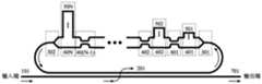
图1为基于环形谐振腔和光开关的自由光谱区可调谐光滤波器结构示意图;Figure 1 is a schematic structural diagram of a tunable optical filter in the free spectral region based on a ring resonator and an optical switch;
图2为2×2光开关直通状态和交叉状态两种不同状态的示意图,其中图2(a)为直通状态示意图,图2(b)为交叉状态示意图。FIG. 2 is a schematic diagram of two different states of a 2×2 optical switch in a direct state and a cross state, wherein FIG. 2( a ) is a schematic diagram of the direct state, and FIG. 2( b ) is a schematic diagram of the cross state.
上述附图中,附图标记含义如下:In the above drawings, the meanings of the reference symbols are as follows:
101、输入光波导;201、中间光波导;301、1×2光开光;101. Input optical waveguide; 201. Intermediate optical waveguide; 301. 1×2 optical switch;
401、2×2光开关;501-50N、长度满足一定倍数关系的N段波导;401, 2×2 optical switch; 501-50N, N-segment waveguide whose length satisfies a certain multiple relationship;
601-60N、长度相同的N段直波导;601-60N, N-segment straight waveguide with the same length;
402、2×2光开关;402, 2×2 optical switch;
302、2×1光开关;302, 2×1 optical switch;
40(N-1)、2×2光开关;701、输出光波导。40(N-1), 2×2 optical switch; 701, output optical waveguide.
具体实施方式Detailed ways
本发明提供了一种新型的基于环形谐振腔和光开关的集成化可重构光滤波器结构,以实现自由光谱区可调谐的滤波功能,进而满足光纤通信技术领域对的光滤波器自由光谱区灵活性的需求。The invention provides a novel integrated reconfigurable optical filter structure based on a ring resonant cavity and an optical switch, so as to realize the tunable filtering function in the free spectral region, thereby satisfying the optical filter free spectral region in the optical fiber communication technology field. The need for flexibility.
为使本发明的目的、技术方案和优点更加清楚明白,以下结合具体实施例,并参照附图,对本发明作进一步的详细说明。In order to make the objectives, technical solutions and advantages of the present invention more clearly understood, the present invention will be further described in detail below in conjunction with specific embodiments and with reference to the accompanying drawings.
说明书与权利要求中所使用的序数例如“第一”、“第二”等的用词,以修饰相应的元件,其本身并不意味着该元件有任何的序数,也不代表某一元件与另一元件的顺序、或是制造方法上的顺序,该些序数的使用仅用来使具有某命名的一元件得以和另一具有相同命名的元件能做出清楚区分。Words such as "first", "second", etc. used in the description and the claims are used to modify the corresponding element, which does not mean that the element has any ordinal number, nor does it mean that a certain element is related to the corresponding element. The order of another element, or the order of the manufacturing method, the ordinal numbers are used only to clearly distinguish an element with a certain name from another element with the same name.
请参阅图1所示,本发明公开一种自由光谱区可调谐光滤波器,包括:Referring to Figure 1, the present invention discloses a tunable optical filter in the free spectral region, including:
输入光波导101,其输入端用于输入待处理的宽带光信号;中间光波导201,其为一个类“U”型波导,与输入光波导101相邻近,构成一个耦合区,用于将输入光信号中通带内的光波耦合到谐振腔中,光波在环形谐振腔内沿逆时针传播;1×2光开关301,其输入端与中间光波导201相连,用于控制耦合至中间光波导201内的光通路切换路径;光波导501、光波导601,分别与1×2光开关301的两输出端相连接;2×2光开关401,其两输入端分别与光波导501、光波导601输出端相连接;光波导502、光波导602,分别与2×2光开关401的两输出端相连接;2×2光开关402,其两输入端分别与光波导502、光波导602输出端相连接;2×1光开关302,其两输入端分别与光波导50N、光波导60N输出端相连接,其输出端与中间光波导201相连,光波导501-50N是长度满足一定倍数关系的N段波导,光波导601-60N是长度相同的N段直波导;中间光波导201、1×2光开关301、(N-1)个2×2光开关、2×1光开关302、以及位于光开关之间的两段光波导构成一个闭合环形谐振腔,光波沿该闭合环形波导逆时针传播,在中间光波导201与输入光波导101相邻近的耦合区内,将光信号中通带内的光波耦合到输出光波导701中,完成可重构光滤波器的滤波功能。The input
输入光波导101,其输入端用于输入待处理的宽带光信号;The input
中间光波导201,其为一个类“U”型波导,与输入光波导101相邻近,构成一个耦合区,用于将输入光信号中通带内的光波耦合到谐振腔中,光波在环形谐振腔内沿逆时针传播;The intermediate
1×2光开关301,其输入端与中间光波导201相连,用于控制耦合至中间光波导201内的光通路切换路径;The 1×2
光波导501、光波导601,分别与1×2光开关301的两输出端相连接;The
具体的,1×2光开关301控制从输入端输入的光信号完全进入光波导501或光波导601。Specifically, the 1×2
2×2光开关401,其两输入端分别与光波导501、光波导601输出端相连接;The 2×2
具体的,如图2所示,其中图2(a)为直通状态示意图,图2(b)为交叉状态示意图。2×2光开关单元为直通状态时,输出端1和输出端2分别输出输入端1和输入端2的信号;光开关单元为交叉状态时,输出端1和输出端2分别输出输入端2和输入端1的信号。Specifically, as shown in FIG. 2 , FIG. 2( a ) is a schematic diagram of a through state, and FIG. 2( b ) is a schematic diagram of a cross state. When the 2×2 optical switch unit is in the straight-through state, the
光波导502、光波导602,分别与2×2光开关401的两输出端相连接;The
2×2光开关402,其两输入端分别与光波导502、光波导602输出端相连接;The 2×2
2×1光开关302,其两输入端分别与光波导50N、光波导60N输出端相连接,其输出端与中间光波导201相连,光波导501-50N是长度满足一定倍数关系的N段波导,光波导601-60N是长度相同的N段直波导;The 2×1
中间光波导201、1×2光开关301、(N-1)个2×2光开关、2×1光开关302、以及位于光开关之间的两段光波导构成一个闭合环形谐振腔,光波沿该闭合环形波导逆时针传播,在中间光波导201与输入光波导101相邻近的耦合区内,将光信号中通带内的光波耦合到输出光波导701中,完成可重构光滤波器的滤波功能。The intermediate
具体的,光波导的长度关系为:假设光波导501的长度为L,则光波导502的长度为2L,光波导503的长度为4L,…,光波导50N的长度为2N-1L,中间光波导201的长度远小于长度L。Specifically, the length relationship of the optical waveguide is: assuming that the length of the
具体的,自由光谱区的大小与谐振腔的长度成反比,其余结构不变时,当谐振腔长度扩展为原结构正整数k倍时,对应的自由光谱区大小为原结构的1/k,本发明中自由光谱区调谐的方法是:Specifically, the size of the free spectral region is inversely proportional to the length of the resonant cavity. When the rest of the structure remains unchanged, when the length of the resonant cavity is expanded to a positive integer k times the original structure, the corresponding free spectral region size is 1/k of the original structure, The method for tuning the free spectral region in the present invention is:
当1×2光开关301的1端口通过,2端口阻断,(N-1)个2×2光开关所有状态均为直通状态,2×1光开关302的1端口通过,2端口阻断时,光信号经过了中间光波导201、光波导501-50N,此时闭合环形谐振腔的长度最长为(2N-1)*L,对应的自由光谱区大小为FSR;When
当1×2光开关301的2端口通过,1端口阻断,2×2光开关401为交叉状态,2×2光开关402-40(N-1)为直通状态,2×1光开关302的1端口通过,2端口阻断时,光信号经过了中间光波导201、光波导601以及光波导(502-50N),此时闭合环形谐振腔的长度为(2N-2)*L,对应的自由光谱区大小为:When port 2 of the 1×2

当1×2光开关301的1端口通过,2端口阻断,2×2光开关(401,402)为交叉状态,2×2光开关(403-40(N-1))为直通状态,2×1光开关302的1端口通过,2端口阻断时,光信号经过了中间光波导201、光波导501、光波导602以及光波导(503-50N),此时闭合环形谐振腔的长度为(2N-3)*L,对应的自由光谱区大小为:When

以此类推,通过控制1×2光开关301、(N-1)个2×2光开关以及2×1光开关302的切换状态,控制光信号在所需长度的光波导中传播的路径,基于此原理,闭合环形谐振腔的长度可以遍历L至(2N-1)*L中每一个长度L的整数倍,即(2N-1)种长度,对应(2N-1)个大小的自由光谱区,从而实现自由光谱区灵活可调谐。By analogy, by controlling the switching states of the 1×2
可选地,光开关单元的状态切换以及环形谐振腔的中心波长调谐通过热光效应或电光效应调节。Optionally, the state switching of the optical switch unit and the tuning of the center wavelength of the ring resonator are regulated by thermo-optic effect or electro-optic effect.
可选地,光开关单元及环形谐振腔可以在铌酸锂、硅、二氧化硅、磷化铟、砷化镓平台上通过半导体工艺制作实现。Optionally, the optical switch unit and the ring resonant cavity can be fabricated and realized by semiconductor technology on lithium niobate, silicon, silicon dioxide, indium phosphide, and gallium arsenide platforms.
以上所述的具体实施例,对本发明的目的、技术方案和有益效果进行了进一步详细说明,应理解的是,以上所述仅为本发明的具体实施例而已,并不用于限制本发明,凡在本发明的精神和原则之内,所做的任何修改、等同替换、改进等,均应包含在本发明的保护范围之内。The specific embodiments described above further describe the purpose, technical solutions and beneficial effects of the present invention in detail. It should be understood that the above-mentioned specific embodiments are only specific embodiments of the present invention, and are not intended to limit the present invention. Within the spirit and principle of the present invention, any modifications, equivalent replacements, improvements, etc. made should be included within the protection scope of the present invention.
Claims (9)
Translated fromChinesePriority Applications (1)
| Application Number | Priority Date | Filing Date | Title |
|---|---|---|---|
| CN201911357781.9ACN111025465B (en) | 2019-12-25 | 2019-12-25 | Tunable Optical Filter in Free Spectral Region |
Applications Claiming Priority (1)
| Application Number | Priority Date | Filing Date | Title |
|---|---|---|---|
| CN201911357781.9ACN111025465B (en) | 2019-12-25 | 2019-12-25 | Tunable Optical Filter in Free Spectral Region |
Publications (2)
| Publication Number | Publication Date |
|---|---|
| CN111025465A CN111025465A (en) | 2020-04-17 |
| CN111025465Btrue CN111025465B (en) | 2020-10-09 |
Family
ID=70214249
Family Applications (1)
| Application Number | Title | Priority Date | Filing Date |
|---|---|---|---|
| CN201911357781.9AActiveCN111025465B (en) | 2019-12-25 | 2019-12-25 | Tunable Optical Filter in Free Spectral Region |
Country Status (1)
| Country | Link |
|---|---|
| CN (1) | CN111025465B (en) |
Families Citing this family (11)
| Publication number | Priority date | Publication date | Assignee | Title |
|---|---|---|---|---|
| CN111781677A (en)* | 2020-06-16 | 2020-10-16 | 深圳市中兴新地技术股份有限公司 | A flat-top optical filter |
| CN111947780B (en)* | 2020-07-30 | 2022-12-06 | 上海交通大学 | Fourier Transform Spectrometer and Spectral Reconstruction Method on Silicon Substrate |
| CN113031162B (en)* | 2021-03-15 | 2022-08-05 | 中国科学院半导体研究所 | Optical filter |
| CN112799174B (en)* | 2021-04-06 | 2021-06-25 | 中国电子科技集团公司信息科学研究院 | A tunable optical filter |
| CN113504610B (en)* | 2021-07-06 | 2023-01-03 | 中国科学院半导体研究所 | High roll-off optical filter |
| CN113466999B (en)* | 2021-07-06 | 2022-10-18 | 中国科学院半导体研究所 | Optical filter and optical communication equipment using the same |
| CN113466998B (en)* | 2021-07-06 | 2022-10-28 | 中国科学院半导体研究所 | Tunable optical filter and optical communication device using same |
| CN113285756B (en)* | 2021-07-22 | 2021-10-22 | 西安奇芯光电科技有限公司 | PLC chip, single-fiber bidirectional optical assembly, optical module and working method |
| CN113433620B (en)* | 2021-08-26 | 2021-11-26 | 中国电子科技集团公司信息科学研究院 | Reconfigurable tunable optical filter |
| CN114563086B (en)* | 2022-04-28 | 2022-07-01 | 南京航空航天大学 | Spectral measurement method and device based on optical switch array |
| CN119916596B (en)* | 2025-04-03 | 2025-07-04 | 之江实验室 | An optical waveguide delay line |
Family Cites Families (4)
| Publication number | Priority date | Publication date | Assignee | Title |
|---|---|---|---|---|
| US7400797B2 (en)* | 2004-10-06 | 2008-07-15 | Corning Incorporated | Transverse closed-loop resonator |
| JP5263045B2 (en)* | 2009-07-15 | 2013-08-14 | 沖電気工業株式会社 | Polarization-independent optical device |
| CN101800397B (en)* | 2010-04-09 | 2011-05-18 | 浙江大学 | Semiconductor laser using semi-wave coupled ring resonator to achieve mode selection |
| JP5632436B2 (en)* | 2012-10-02 | 2014-11-26 | 日本電信電話株式会社 | Optical wavelength filter |
- 2019
- 2019-12-25CNCN201911357781.9Apatent/CN111025465B/enactiveActive
Also Published As
| Publication number | Publication date |
|---|---|
| CN111025465A (en) | 2020-04-17 |
Similar Documents
| Publication | Publication Date | Title |
|---|---|---|
| CN111025465B (en) | Tunable Optical Filter in Free Spectral Region | |
| CN113031163B (en) | Optical filter structure and optical filter | |
| CN104317068A (en) | Integrated optical filter with center wavelength and filter bandwidth both adjustable independently | |
| CN105549157B (en) | A kind of tunable optical notch filter based on micro-ring resonator | |
| CN106371174A (en) | Optical bandpass filter based on double microring-Mach Zehnder interference structure | |
| US6602000B1 (en) | Reconfigurable add/drop for optical fiber communication systems | |
| CN112799174B (en) | A tunable optical filter | |
| CN113031162B (en) | Optical filter | |
| CN113466998B (en) | Tunable optical filter and optical communication device using same | |
| EP2049929B1 (en) | Ultra-narrow bandpass filter | |
| CN110596819B (en) | Narrow-band optical filter based on micro-ring resonator | |
| CN110927884B (en) | Integrated high roll-off optical filter | |
| CN110927885B (en) | Narrowband Optical Filter Based on Microdisk Resonator | |
| CN107065073A (en) | Broad band wavelength bandwidth tunable filter based on cascade interweaved device | |
| WO2005036793A1 (en) | Optical add-filtering switching device | |
| US7496253B2 (en) | Wide passband optical interleaver | |
| CN110850527B (en) | Integrated Optical Filter | |
| CN113031164A (en) | Optical filter structure and optical filter | |
| CN117148503A (en) | Reconfigurable multi-channel integrated flat-top optical filter based on cascaded microring resonant unit | |
| KR20210005667A (en) | Reconfigurable optical add-drop multiplexer with low power consumption | |
| CN113433620B (en) | Reconfigurable tunable optical filter | |
| CN113466999B (en) | Optical filter and optical communication equipment using the same | |
| CN105700082A (en) | Adjustable interleaver based on silicon-substrate Michelson GT interferometer | |
| Yang et al. | Integrated 4-channel wavelength selective switch based on second-order micro-ring resonators | |
| CN113504610B (en) | High roll-off optical filter |
Legal Events
| Date | Code | Title | Description |
|---|---|---|---|
| PB01 | Publication | ||
| PB01 | Publication | ||
| SE01 | Entry into force of request for substantive examination | ||
| SE01 | Entry into force of request for substantive examination | ||
| GR01 | Patent grant | ||
| GR01 | Patent grant |