CN111016628B - Central drive integrated electric drive system - Google Patents
Central drive integrated electric drive systemDownload PDFInfo
- Publication number
- CN111016628B CN111016628BCN201911420988.6ACN201911420988ACN111016628BCN 111016628 BCN111016628 BCN 111016628BCN 201911420988 ACN201911420988 ACN 201911420988ACN 111016628 BCN111016628 BCN 111016628B
- Authority
- CN
- China
- Prior art keywords
- rotating sleeve
- gear
- drive system
- electric drive
- sleeve
- Prior art date
- Legal status (The legal status is an assumption and is not a legal conclusion. Google has not performed a legal analysis and makes no representation as to the accuracy of the status listed.)
- Active
Links
- 230000008859changeEffects0.000claimsabstractdescription19
- 230000009467reductionEffects0.000claimsdescription15
- 230000007246mechanismEffects0.000claimsdescription9
- 230000009347mechanical transmissionEffects0.000abstractdescription6
- 238000004519manufacturing processMethods0.000abstractdescription4
- 230000009286beneficial effectEffects0.000abstractdescription3
- 238000010438heat treatmentMethods0.000abstractdescription2
- 230000005540biological transmissionEffects0.000description6
- 238000005452bendingMethods0.000description2
- 230000033228biological regulationEffects0.000description1
- 239000003638chemical reducing agentSubstances0.000description1
- 238000010586diagramMethods0.000description1
- 230000007613environmental effectEffects0.000description1
- 239000000446fuelSubstances0.000description1
- 230000020169heat generationEffects0.000description1
- 238000009434installationMethods0.000description1
- 238000000034methodMethods0.000description1
- 230000009466transformationEffects0.000description1
- 238000000844transformationMethods0.000description1
- 238000003466weldingMethods0.000description1
Images

Classifications
- B—PERFORMING OPERATIONS; TRANSPORTING
- B60—VEHICLES IN GENERAL
- B60K—ARRANGEMENT OR MOUNTING OF PROPULSION UNITS OR OF TRANSMISSIONS IN VEHICLES; ARRANGEMENT OR MOUNTING OF PLURAL DIVERSE PRIME-MOVERS IN VEHICLES; AUXILIARY DRIVES FOR VEHICLES; INSTRUMENTATION OR DASHBOARDS FOR VEHICLES; ARRANGEMENTS IN CONNECTION WITH COOLING, AIR INTAKE, GAS EXHAUST OR FUEL SUPPLY OF PROPULSION UNITS IN VEHICLES
- B60K7/00—Disposition of motor in, or adjacent to, traction wheel
- B60K7/0007—Disposition of motor in, or adjacent to, traction wheel the motor being electric
- B—PERFORMING OPERATIONS; TRANSPORTING
- B60—VEHICLES IN GENERAL
- B60K—ARRANGEMENT OR MOUNTING OF PROPULSION UNITS OR OF TRANSMISSIONS IN VEHICLES; ARRANGEMENT OR MOUNTING OF PLURAL DIVERSE PRIME-MOVERS IN VEHICLES; AUXILIARY DRIVES FOR VEHICLES; INSTRUMENTATION OR DASHBOARDS FOR VEHICLES; ARRANGEMENTS IN CONNECTION WITH COOLING, AIR INTAKE, GAS EXHAUST OR FUEL SUPPLY OF PROPULSION UNITS IN VEHICLES
- B60K17/00—Arrangement or mounting of transmissions in vehicles
- B60K17/04—Arrangement or mounting of transmissions in vehicles characterised by arrangement, location or kind of gearing
- B60K17/06—Arrangement or mounting of transmissions in vehicles characterised by arrangement, location or kind of gearing of change-speed gearing
- B60K17/08—Arrangement or mounting of transmissions in vehicles characterised by arrangement, location or kind of gearing of change-speed gearing of mechanical type
Landscapes
- Engineering & Computer Science (AREA)
- Chemical & Material Sciences (AREA)
- Combustion & Propulsion (AREA)
- Transportation (AREA)
- Mechanical Engineering (AREA)
- Motor Power Transmission Devices (AREA)
- Connection Of Motors, Electrical Generators, Mechanical Devices, And The Like (AREA)
- Arrangement Or Mounting Of Propulsion Units For Vehicles (AREA)
Abstract
Description
Translated fromChinese技术领域technical field
本发明属于两轮车驱动技术领域,具体涉及一种中央驱动集成化电驱动系统。The invention belongs to the technical field of two-wheeled vehicle drive, and in particular relates to a central drive integrated electric drive system.
背景技术Background technique
随着环保法规的日益严苛,以纯电为动力的汽车、两轮车、三轮车为代表的新能源交通工具取代传统燃油交通工具已经是大势所趋。现有的两轮电动车普遍采用轮毂电机和电机侧挂式结构。With the increasingly stringent environmental regulations, it is a general trend that new energy vehicles represented by pure electric vehicles, two-wheelers and tricycles replace traditional fuel vehicles. Existing two-wheeled electric vehicles generally use in-wheel motors and motor side-mounted structures.
轮毂电机采用低速直流电机直接驱动,不仅效率相对较低,发热量大,还由于电机体积大、重量重,打破了车轮结构原有的平衡,对操控性能及安全性方面会有一定影响。The in-wheel motor is directly driven by a low-speed DC motor, which not only has relatively low efficiency and large heat generation, but also breaks the original balance of the wheel structure due to the large size and heavy weight of the motor, which will have a certain impact on the handling performance and safety.
侧挂式结构将电机和变速系统(变速箱或减速器)置于驱动轮的同一侧,尽管可以采用高速电机以提高机械效率,但变速机构与电机的重量较重,导致车轮的平衡性不佳,尤其对于两轮车的影响更为明显。The side-mounted structure places the motor and the transmission system (gearbox or reducer) on the same side of the driving wheel. Although a high-speed motor can be used to improve mechanical efficiency, the weight of the transmission mechanism and the motor is heavy, resulting in poor balance of the wheels. better, especially for two-wheeled vehicles.
因此,急需设计一种全新的电驱动系统,能够兼具轮毂电机和电机侧挂式结构的优点,弥补二者的不足。Therefore, it is urgent to design a new electric drive system, which can combine the advantages of the in-wheel motor and the motor side-mounted structure, and make up for the shortcomings of the two.
发明内容SUMMARY OF THE INVENTION
有鉴于此,本发明提供一种中央驱动集成化电驱动系统,结构布局紧凑,车辆平衡性好,机械传动效率高,制造成本低。In view of this, the present invention provides a central drive integrated electric drive system with compact structure and layout, good vehicle balance, high mechanical transmission efficiency and low manufacturing cost.
为实现上述目的,本发明技术方案如下:For achieving the above object, the technical scheme of the present invention is as follows:
一种中央驱动集成化电驱动系统,包括固定安装在车架上的固定轴,其关键在于:所述固定轴上以转动配合的方式套装有沿其长度方向延伸的转动套,所述转动套上布置有动力装置、轮毂和变速装置,其中轮毂位于动力装置和变速装置之间,所述动力装置经转动套驱动变速装置工作,变速装置与轮毂动力连接。A central drive integrated electric drive system includes a fixed shaft fixedly installed on a vehicle frame, the key point of which is: a rotating sleeve extending along its length direction is sheathed on the fixed shaft in a rotating fit manner, and the rotating sleeve is A power device, a wheel hub and a speed change device are arranged on it, wherein the wheel hub is located between the power device and the speed change device, the power device drives the speed change device to work through the rotating sleeve, and the speed change device is powered with the wheel hub.
采用上述结构,集成化电驱动系统工作时,动力装置驱动转动套转动,转动套的转速经变速装置驱动轮毂转动,即驱动两轮车行驶。通过变速装置的设置,保证了动力装置能够直接采用高速电机,提高了电驱动系统的机械传动效率,并且动力装置和变速装置对称设置在轮毂的左右两侧,不仅实现了中央驱动输出,而且车辆的受力更加均衡,提升了车辆的操控性和安全性。With the above structure, when the integrated electric drive system works, the power device drives the rotating sleeve to rotate, and the rotational speed of the rotating sleeve drives the wheel hub to rotate through the speed change device, that is, drives the two-wheeled vehicle to travel. Through the setting of the speed change device, it is ensured that the power device can directly use a high-speed motor, which improves the mechanical transmission efficiency of the electric drive system, and the power device and the speed change device are symmetrically arranged on the left and right sides of the wheel hub, which not only realizes the central drive output, but also the vehicle. The force is more balanced, which improves the handling and safety of the vehicle.
电驱动系统装配在车辆上后,固定轴与车架固定连接,车辆的重量由固定轴完全承载,由于转动套与固定轴之间有装配间隙,所以固定轴适量的弯曲变形不会影响系统的传动精度。After the electric drive system is assembled on the vehicle, the fixed shaft is fixedly connected to the frame, and the weight of the vehicle is fully borne by the fixed shaft. Since there is an assembly gap between the rotating sleeve and the fixed shaft, the proper amount of bending deformation of the fixed shaft will not affect the system performance. Transmission accuracy.
作为优选:所述动力装置采用电机,该电机的转子为空心转子,所述转动套固定安装在空心转子内。采用上述结构,相当于整个高速电机直接套设在转动套上,可使电驱动系统的结构更加紧凑。Preferably, the power device adopts a motor, the rotor of the motor is a hollow rotor, and the rotating sleeve is fixedly installed in the hollow rotor. By adopting the above structure, it is equivalent that the entire high-speed motor is directly sleeved on the rotating sleeve, which can make the structure of the electric drive system more compact.
作为优选:所述转动套通过花键连接在空心转子内。采用上述结构,便于装配。Preferably, the rotating sleeve is connected in the hollow rotor through splines. By adopting the above structure, it is convenient to assemble.
作为优选:所述变速装置由减速机构组成,其包括与转动套固接的输入齿轮,以及与轮毂固接的输出齿轮,其中输入齿轮与输出齿轮之间具有至少一级减速。Preferably, the speed change device is composed of a deceleration mechanism, which includes an input gear fixed to the rotating sleeve and an output gear fixed to the hub, wherein there is at least one stage of deceleration between the input gear and the output gear.
作为优选:所述减速机构还包括与转动套平行设置的减速轴,减速轴的两端固定安装有第一减速齿轮和第二减速齿轮,第一减速齿轮与所述输入齿轮啮合,第二减速齿轮与所述输出齿轮啮合。采用上述结构,能够对电机进行二级减速。Preferably, the deceleration mechanism further includes a deceleration shaft arranged in parallel with the rotating sleeve, both ends of the deceleration shaft are fixedly mounted with a first deceleration gear and a second deceleration gear, the first deceleration gear meshes with the input gear, and the second deceleration gear is engaged with the input gear. A gear meshes with the output gear. With the above configuration, the motor can be decelerated in two stages.
作为优选:所述输入齿轮转动套装在固定轴的端部,并与所述转动套的端部焊接。采用上述结构,便于转动套与输入齿轮之间的固定连接。Preferably, the input gear is rotatably sleeved on the end of the fixed shaft, and is welded with the end of the rotation sleeve. With the above structure, the fixed connection between the rotating sleeve and the input gear is facilitated.
作为优选:所述转动套的中间位置转动套装有输出套,所述轮毂和输出齿轮均固套在该输出套上。采用上述结构,便于轮毂与输出齿轮之间的固定连接。Preferably, an output sleeve is provided in the middle position of the rotating sleeve, and the hub and the output gear are fixedly sleeved on the output sleeve. With the above structure, the fixed connection between the hub and the output gear is facilitated.
作为优选:所述输出套的两端通过深沟球轴承转动支承在电驱动系统的外壳体上。采用上述结构,便于安装。Preferably, both ends of the output sleeve are rotatably supported on the outer casing of the electric drive system through deep groove ball bearings. With the above structure, installation is convenient.
作为优选:所述输入齿轮与输出套之间抵接有推力球轴承。采用上述结构,输入齿轮内端通过推力球轴承与输出套抵接,能够使电驱动系统的结构更加紧凑。Preferably, a thrust ball bearing abuts between the input gear and the output sleeve. With the above structure, the inner end of the input gear is in contact with the output sleeve through the thrust ball bearing, so that the structure of the electric drive system can be made more compact.
作为优选:所述转动套的一端设有编码器。采用上述结构,能够将电机的转速转化成信号形式反馈给驱动系统。Preferably, an encoder is provided at one end of the rotating sleeve. With the above structure, the rotational speed of the motor can be converted into a signal form and fed back to the drive system.
与现有技术相比,本发明的有益效果是:Compared with the prior art, the beneficial effects of the present invention are:
采用本发明提供的中央驱动集成化电驱动系统,动力传递路径为:电机→空心转子→转动套→输入齿轮→第一减速齿轮→第二减速齿轮→输出齿轮→输出套→轮毂,具有机械传动效率高、电机发热率低、平衡性好、操控性好、安全系数高、结构紧凑、制造成本低等技术优势。Using the central drive integrated electric drive system provided by the present invention, the power transmission path is: motor→hollow rotor→rotating sleeve→input gear→first reduction gear→second reduction gear→output gear→output sleeve→wheel hub, with mechanical transmission High efficiency, low motor heating rate, good balance, good controllability, high safety factor, compact structure, low manufacturing cost and other technical advantages.
附图说明Description of drawings
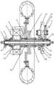
图1为集成化电驱动系统的剖视图;1 is a cross-sectional view of an integrated electric drive system;
图2为两轮车后轮位置的示意图。Figure 2 is a schematic diagram of the position of the rear wheels of the two-wheeled vehicle.
具体实施方式Detailed ways
以下结合实施例和附图对本发明作进一步说明。The present invention will be further described below with reference to the embodiments and the accompanying drawings.
如图1和2所示,一种中央驱动集成化电驱动系统,车架1上固定安装有固定轴2,固定轴2用于支撑整个电驱动系统,固定轴2上套装有沿其长度方向延伸的转动套3,转动套3工作时相对于固定轴2转动运动,固定轴2承载后的适量弯曲变形不会影响系统的传动精度,转动套3上从左至右依次设置有动力装置、轮毂5和变速装置,本实施例中,动力装置为电机4,变速装置为减速机构6,集成化电驱动系统工作时,电机4驱动转动套3转动,转动套3的转速经减速机构6减速后驱动轮毂5转动,即驱动两轮车行驶,通过减速机构6的设置,保证了电机4能够直接采用高速电机,提高了电驱动系统的机械传动效率,并且电机4和减速机构6对称设置在轮毂5的左右两侧,不仅实现了中央驱动输出,而且车辆的受力更加均衡,提升了车辆的操控性和安全性。As shown in Figures 1 and 2, a central drive integrated electric drive system, the frame 1 is fixedly mounted with a fixed shaft 2, the fixed shaft 2 is used to support the entire electric drive system, and the fixed shaft 2 is sleeved along its length. The extended rotating sleeve 3, the rotating sleeve 3 rotates relative to the fixed shaft 2 when it is working, and the proper amount of bending deformation after the fixed shaft 2 is carried will not affect the transmission accuracy of the system. The
进一步的,电机4优选采用高速电机,其转子为空心转子4a,转动套3通过花键7固套在空心转子4a内;轮毂5通过输出套8转动安装在转动套3的中部;减速机构6包括与转动套3平行设置的减速轴6c,减速轴6c的两端固定安装有第一减速齿轮6d和第二减速齿轮6e,转动套3上固定连接有与第一减速齿轮6d啮合的输入齿轮6a,输出套8上固定连接有与第二减速齿轮6e啮合的输出齿轮6b,基于该结构布置,驱动系统的动力传递路径为:电机4→空心转子4a→转动套3→输入齿轮6a→第一减速齿轮6d→减速轴6c→第二减速齿轮6e→输出齿轮6b→输出套8→轮毂5,从而驱动车辆的轮子转动。Further, the motor 4 preferably adopts a high-speed motor, and its rotor is a
输出套8的内圈转动套设在转动套3上,转动套3的内圈又转动套设在固定轴2上,实现了多层多级式装配,使得系统的结构更加紧凑,并有利于降低制造成本。The inner ring of the output sleeve 8 is rotatably sleeved on the rotating sleeve 3, and the inner ring of the rotating sleeve 3 is rotatably sleeved on the fixed shaft 2, which realizes multi-layer and multi-stage assembly, which makes the structure of the system more compact and is beneficial to Reduce manufacturing costs.
为便于装配输出套8,输出套8的两端通过深沟球轴承8a转动支承在电驱动系统的外壳体9上,输出套8的内部为中空结构,并套设于转动套3上,轮毂5和输出齿轮6b均通过花键形式固套在输出套8上。In order to facilitate the assembly of the output sleeve 8, both ends of the output sleeve 8 are rotatably supported on the outer casing 9 of the electric drive system through deep
进一步的,输入齿轮6a与输出套8之间抵接有推力球轴承10,以满足结构紧凑、机械传动可靠的要求。Further, a thrust ball bearing 10 abuts between the
为实现转动套3与输入齿轮6a之间的固定连接,输入齿轮6a以焊接方式安装在转动套3的端部,且输入齿轮6a通过轴承转动安装在固定轴2的右端,同时这样设计还可方便产品装配。In order to realize the fixed connection between the rotating sleeve 3 and the
最后需要说明的是,上述描述仅仅为本发明的优选实施例,本领域的普通技术人员在本发明的启示下,在不违背本发明宗旨及权利要求的前提下,可以做出多种类似的表示,这样的变换均落入本发明的保护范围之内。Finally, it should be noted that the above description is only a preferred embodiment of the present invention, and those of ordinary skill in the art can make a variety of similar It is indicated that such transformations fall within the protection scope of the present invention.
Claims (6)
Priority Applications (1)
| Application Number | Priority Date | Filing Date | Title |
|---|---|---|---|
| CN201911420988.6ACN111016628B (en) | 2019-12-31 | 2019-12-31 | Central drive integrated electric drive system |
Applications Claiming Priority (1)
| Application Number | Priority Date | Filing Date | Title |
|---|---|---|---|
| CN201911420988.6ACN111016628B (en) | 2019-12-31 | 2019-12-31 | Central drive integrated electric drive system |
Publications (2)
| Publication Number | Publication Date |
|---|---|
| CN111016628A CN111016628A (en) | 2020-04-17 |
| CN111016628Btrue CN111016628B (en) | 2022-04-22 |
Family
ID=70201730
Family Applications (1)
| Application Number | Title | Priority Date | Filing Date |
|---|---|---|---|
| CN201911420988.6AActiveCN111016628B (en) | 2019-12-31 | 2019-12-31 | Central drive integrated electric drive system |
Country Status (1)
| Country | Link |
|---|---|
| CN (1) | CN111016628B (en) |
Families Citing this family (1)
| Publication number | Priority date | Publication date | Assignee | Title |
|---|---|---|---|---|
| CN113696712A (en)* | 2021-06-28 | 2021-11-26 | 太仓市悦博电动科技有限公司 | Quick-release hub motor |
Citations (7)
| Publication number | Priority date | Publication date | Assignee | Title |
|---|---|---|---|---|
| EP0139714A1 (en)* | 1983-04-12 | 1985-05-08 | Ake Enocson | POWER TRANSMISSION SYSTEM FOR BICYCLE. |
| CN101244752A (en)* | 2008-03-03 | 2008-08-20 | 西南大学 | Side-mounted cone-disc adaptive two-speed automatic transmission hub |
| CN101244688A (en)* | 2008-03-03 | 2008-08-20 | 西南大学 | Side-mounted clutch plate adaptive two-speed automatic transmission hub |
| US7497285B1 (en)* | 2007-11-15 | 2009-03-03 | Vladimir Radev | Hybrid electric vehicle |
| WO2015097483A1 (en)* | 2013-12-24 | 2015-07-02 | Mira Limited | An axle assembly, a steering mechanism, a vehicle, and a trailer |
| CN109398069A (en)* | 2018-10-29 | 2019-03-01 | 山东理工大学 | A kind of integrated form external rotor electric wheels integral structure and assembly method |
| JP2019209703A (en)* | 2018-05-31 | 2019-12-12 | 日本電産シンポ株式会社 | In-wheel motor driving device, and vehicle with the same |
Family Cites Families (13)
| Publication number | Priority date | Publication date | Assignee | Title |
|---|---|---|---|---|
| US6100615A (en)* | 1998-05-11 | 2000-08-08 | Birkestrand; Orville J. | Modular motorized electric wheel hub assembly for bicycles and the like |
| CN2879513Y (en)* | 2006-02-28 | 2007-03-14 | 蔡贵席 | Electric shift hub |
| CN101311018B (en)* | 2008-06-18 | 2010-09-29 | 西南大学 | Electric Cone Disc Clutch Cam Adaptive Automatic Transmission Hub |
| CN101254745B (en)* | 2008-03-05 | 2010-06-09 | 西南大学 | Planetary cone disc type automatic variable speed electric hub |
| JP5401686B2 (en)* | 2009-02-13 | 2014-01-29 | 株式会社 神崎高級工機製作所 | Wheel hub drive unit |
| WO2010126039A1 (en)* | 2009-04-30 | 2010-11-04 | Ntn株式会社 | Power-assisted bicycle including regenerative mechanism |
| EP2842764B1 (en)* | 2013-08-26 | 2017-01-18 | Innotorq GmbH | Wheel hub transmission unit for a drive wheel of a vehicle, drive wheel and vehicle with an auxiliary drive |
| TWI619622B (en)* | 2014-01-03 | 2018-04-01 | Zeng Sheng Cai | Vehicle transmission |
| WO2016179761A1 (en)* | 2015-05-08 | 2016-11-17 | 铁兵 | Speed reduction electric hub system and electric vehicle |
| CN205150145U (en)* | 2015-10-29 | 2016-04-13 | 杨玉婷 | Vehicle hub structure |
| CN106926690B (en)* | 2017-03-23 | 2019-07-02 | 重庆大学 | Electric wheel hub drive |
| CN108638838A (en)* | 2018-05-10 | 2018-10-12 | 北京长城华冠汽车科技股份有限公司 | Electric drive hub system and vehicle with the electric drive hub system |
| CN110203058A (en)* | 2019-05-31 | 2019-09-06 | 贵州航天林泉电机有限公司 | A kind of wheel hub electric drive assembly of parallel shaft (speed) reducer |
- 2019
- 2019-12-31CNCN201911420988.6Apatent/CN111016628B/enactiveActive
Patent Citations (7)
| Publication number | Priority date | Publication date | Assignee | Title |
|---|---|---|---|---|
| EP0139714A1 (en)* | 1983-04-12 | 1985-05-08 | Ake Enocson | POWER TRANSMISSION SYSTEM FOR BICYCLE. |
| US7497285B1 (en)* | 2007-11-15 | 2009-03-03 | Vladimir Radev | Hybrid electric vehicle |
| CN101244752A (en)* | 2008-03-03 | 2008-08-20 | 西南大学 | Side-mounted cone-disc adaptive two-speed automatic transmission hub |
| CN101244688A (en)* | 2008-03-03 | 2008-08-20 | 西南大学 | Side-mounted clutch plate adaptive two-speed automatic transmission hub |
| WO2015097483A1 (en)* | 2013-12-24 | 2015-07-02 | Mira Limited | An axle assembly, a steering mechanism, a vehicle, and a trailer |
| JP2019209703A (en)* | 2018-05-31 | 2019-12-12 | 日本電産シンポ株式会社 | In-wheel motor driving device, and vehicle with the same |
| CN109398069A (en)* | 2018-10-29 | 2019-03-01 | 山东理工大学 | A kind of integrated form external rotor electric wheels integral structure and assembly method |
Non-Patent Citations (1)
| Title |
|---|
| 小型扭矩回差式两挡自动变速器;薛荣生等;《中国机械工程》;20150821;2249-2253* |
Also Published As
| Publication number | Publication date |
|---|---|
| CN111016628A (en) | 2020-04-17 |
Similar Documents
| Publication | Publication Date | Title |
|---|---|---|
| CN100588588C (en) | A two-wheel electric vehicle | |
| CN206871295U (en) | A kind of longitudinal motor driven systems of bicycle | |
| CN106427551B (en) | A kind of shaft two of exempting from for electric vehicle keeps off variable ratio drive system | |
| CN203401963U (en) | Motor-driven hub reduction system | |
| CN104986030B (en) | Electric wheel side drive system and its driving method | |
| CN201211839Y (en) | Double motor driving device of electric bicycle | |
| CN103448537A (en) | Motor-driven hub reduction system | |
| CN203318154U (en) | Integration drive front axle assembly for electric vehicle | |
| CN107933272A (en) | A kind of integrated form planetary gear speed-reduction differential speed motor for new-energy automobile | |
| CN111016628B (en) | Central drive integrated electric drive system | |
| CN101318536A (en) | electric bicycle | |
| CN203039496U (en) | All-in-one two-shift motor transmission for pure electric automobile | |
| CN1815856A (en) | Electric vehicle coaxial mid-mounted motor drive device | |
| CN207683334U (en) | Bridge before a kind of new-energy automobile Monobloc | |
| CN212500858U (en) | Motorcycle electric power assembly | |
| CN214900524U (en) | Coaxial line type driving motor assembly | |
| CN211969152U (en) | Dual-motor driving device and electric forklift | |
| CN116398609A (en) | New energy automobile speed reducer of cantilever integrated motor gear shaft | |
| CN201142616Y (en) | Electric wheel hub motor | |
| CN201077349Y (en) | Electromechanical coaxial transmission mechanism for electromechanical dual-drive electric vehicles | |
| CN108880092B (en) | Rotor integral bearing type driving motor for vehicle | |
| CN2936819Y (en) | Drive device of two-wheel electric vehicle | |
| CN211731023U (en) | A central drive electric drive system assembly | |
| CN202295198U (en) | Motor-driven lithium battery power-assisted tricycle | |
| CN201009987Y (en) | Model tricycle with improved toothed wheel |
Legal Events
| Date | Code | Title | Description |
|---|---|---|---|
| PB01 | Publication | ||
| PB01 | Publication | ||
| SE01 | Entry into force of request for substantive examination | ||
| SE01 | Entry into force of request for substantive examination | ||
| GR01 | Patent grant | ||
| GR01 | Patent grant |