CN110998398B - Fiber extender port, assembly and method of making same - Google Patents
Fiber extender port, assembly and method of making sameDownload PDFInfo
- Publication number
- CN110998398B CN110998398BCN201880053104.5ACN201880053104ACN110998398BCN 110998398 BCN110998398 BCN 110998398BCN 201880053104 ACN201880053104 ACN 201880053104ACN 110998398 BCN110998398 BCN 110998398B
- Authority
- CN
- China
- Prior art keywords
- connection port
- port
- extender
- feature
- passage
- Prior art date
- Legal status (The legal status is an assumption and is not a legal conclusion. Google has not performed a legal analysis and makes no representation as to the accuracy of the status listed.)
- Active
Links
Images


Classifications
- G—PHYSICS
- G02—OPTICS
- G02B—OPTICAL ELEMENTS, SYSTEMS OR APPARATUS
- G02B6/00—Light guides; Structural details of arrangements comprising light guides and other optical elements, e.g. couplings
- G02B6/24—Coupling light guides
- G02B6/36—Mechanical coupling means
- G02B6/38—Mechanical coupling means having fibre to fibre mating means
- G02B6/3807—Dismountable connectors, i.e. comprising plugs
- G02B6/381—Dismountable connectors, i.e. comprising plugs of the ferrule type, e.g. fibre ends embedded in ferrules, connecting a pair of fibres
- G02B6/3825—Dismountable connectors, i.e. comprising plugs of the ferrule type, e.g. fibre ends embedded in ferrules, connecting a pair of fibres with an intermediate part, e.g. adapter, receptacle, linking two plugs
- G—PHYSICS
- G02—OPTICS
- G02B—OPTICAL ELEMENTS, SYSTEMS OR APPARATUS
- G02B6/00—Light guides; Structural details of arrangements comprising light guides and other optical elements, e.g. couplings
- G02B6/24—Coupling light guides
- G02B6/36—Mechanical coupling means
- G02B6/38—Mechanical coupling means having fibre to fibre mating means
- G02B6/3807—Dismountable connectors, i.e. comprising plugs
- G02B6/389—Dismountable connectors, i.e. comprising plugs characterised by the method of fastening connecting plugs and sockets, e.g. screw- or nut-lock, snap-in, bayonet type
- G—PHYSICS
- G02—OPTICS
- G02B—OPTICAL ELEMENTS, SYSTEMS OR APPARATUS
- G02B6/00—Light guides; Structural details of arrangements comprising light guides and other optical elements, e.g. couplings
- G02B6/24—Coupling light guides
- G02B6/36—Mechanical coupling means
- G02B6/38—Mechanical coupling means having fibre to fibre mating means
- G02B6/3807—Dismountable connectors, i.e. comprising plugs
- G02B6/3897—Connectors fixed to housings, casing, frames or circuit boards
- G—PHYSICS
- G02—OPTICS
- G02B—OPTICAL ELEMENTS, SYSTEMS OR APPARATUS
- G02B6/00—Light guides; Structural details of arrangements comprising light guides and other optical elements, e.g. couplings
- G02B6/44—Mechanical structures for providing tensile strength and external protection for fibres, e.g. optical transmission cables
- G02B6/4439—Auxiliary devices
- G02B6/444—Systems or boxes with surplus lengths
- G02B6/4453—Cassettes
Landscapes
- Physics & Mathematics (AREA)
- General Physics & Mathematics (AREA)
- Optics & Photonics (AREA)
- Mechanical Coupling Of Light Guides (AREA)
Abstract
Translated fromChinese
Description
Translated fromChinese本申请要求以下项的权益:提交于2017年6月28日的美国专利申请号62/526,195;提交于2018年6月26日的美国申请号16/018,918;提交于2018年6月26日的美国申请号16/018,988;以及提交于2018年6月26日的美国申请序列号16/019,008;所述申请的内容是本文的依据并且全文以引用方式并入本文。This application claims the benefit of: US Patent Application No. 62/526,195, filed June 28, 2017; US Application No. 16/018,918, filed June 26, 2018; US Application No. 16/018,988; and US Application Serial No. 16/019,008, filed June 26, 2018; the contents of which are hereby relied upon and are incorporated herein by reference in their entirety.
本申请根据专利法还要求以下项的优先权:提交于2017年11月30日的国际专利申请序列号PCT/US2017/064092;提交于2017年11月30日的国际专利申请序列号PCT/US2017/064095;提交于2018年6月26日的国际专利申请序列号PCT/US2018/039484;提交于2018年6月26日的国际专利申请序列号PCT/US2018/039485;以及提交于2018年6月26日的国际专利申请序列号PCT/US2018/039494;所有专利申请均指定美国,并且所述专利申请的内容是本文的依据并且全文以引用方式并入本文。This application also claims priority under patent law to: International Patent Application Serial No. PCT/US2017/064092 filed on November 30, 2017; International Patent Application Serial No. PCT/US2017 filed on November 30, 2017 /064095; International Patent Application Serial No. PCT/US2018/039484, filed June 26, 2018; International Patent Application Serial No. PCT/US2018/039485, filed June 26, 2018; and June 2018 International Patent Application Serial No. PCT/US2018/039494 on 26; all patent applications designate the United States and the contents of said patent applications are hereby relied upon and are incorporated by reference in their entirety.
技术领域technical field
本公开涉及提供至少一个光学连接端口的光纤装置以及其制造方法。更具体地,本公开涉及包括一个或多个连接端口和与所述连接端口相关联以用于固定光学连接器的固定特征的光纤延长器端口及其制造方法。The present disclosure relates to fiber optic devices that provide at least one optical connection port and methods of making the same. More particularly, the present disclosure relates to fiber optic extender ports including one or more connection ports and securing features associated with the connection ports for securing an optical connector and methods of making the same.
背景技术Background technique
光纤越来越多地用于多种应用,包括但不限于宽带语音、视频和数据传输。随着带宽需求的增加,光纤正更深入地迁移到通信网络中,诸如,在光纤到驻地应用(诸如FTTx、5G等)中。随着光纤更深入地延伸到通信网络中,对以快速且容易的方式在户外应用中形成牢固的光学连接的需求是显而易见的。为了解决对在通信网络中形成快速、可靠且牢固的光学连接的这种需要,开发了诸如
还开发了用于与硬化连接器形成光学连接的多端口装置。现有技术的多端口装置具有穿过外壳的壁安装的多个插座,用于保护外壳内部的室内连接器,所述室内连接器与分支或分接电缆的外部硬化连接器形成光学连接。Multiport devices have also been developed for making optical connections with hardened connectors. Prior art multiport devices have a plurality of receptacles mounted through the wall of the housing to protect the indoor connectors inside the housing that form optical connections with the outer hardened connectors of the drop or drop cables.
不同的分支或分接电缆可能需要不同的长度来到达期望的连接位置。使用工厂端接的解决方案,通常会提供分接电缆的若干长度,并且用户可使用最适合所需链路长度的接插分接电缆的长度。然而,如果长度与所需的链路长度不完全匹配,则这可能需要技术来存放若干不同长度的分接电缆和大量备用电缆存储。Different branch or drop cables may require different lengths to reach the desired connection location. With factory-terminated solutions, drop cables are typically available in several lengths, and the user can use the length of the patch drop cable that best suits the desired link length. However, if the length does not exactly match the desired link length, this may require technology to store several drop cables of different lengths and a large amount of spare cable storage.
因此,存在对于装置的未解决的需求,所述装置允许网络运营商灵活地快速且容易地形成光学连接以扩展光学网络的范围,同时还解决与有限的空间、组织或美学相关的问题。Accordingly, there is an unresolved need for a device that allows network operators the flexibility to quickly and easily form optical connections to extend the reach of optical networks, while also addressing issues related to limited space, organization or aesthetics.
发明内容SUMMARY OF THE INVENTION
本公开涉及延长器端口,其包括至少一个连接端口和与所述连接端口相关联的固定特征。还公开了制造装置的方法。所述装置可具有诸如本文所公开的任何合适的构造,这种连接端口被键接用于阻止非顺应性连接器插入并潜在地对装置造成损坏。The present disclosure relates to extender ports that include at least one connection port and a securing feature associated with the connection port. Methods of making the device are also disclosed. The device may have any suitable configuration, such as those disclosed herein, such that the connection ports are keyed to prevent insertion of non-compliant connectors and potential damage to the device.
本公开的一个方面涉及延长器端口,所述延长器端口包括壳体、第一连接端口、与所述连接端口通路相关联的至少一个固定特征和用于偏置所述至少一个固定特征的一部分的至少一个固定特征弹性构件。所述第一连接端口设置在所述延长器端口上,其中所述至少一个连接端口包括从所述延长器端口的外表面延伸到所述延长器端口的腔体中并且限定连接端口通路的光学连接器开口。One aspect of the present disclosure relates to an extender port that includes a housing, a first connection port, at least one securing feature associated with the connection port passage, and a portion for biasing the at least one securing feature of at least one fixed feature of the elastic member. The first connection port is disposed on the extender port, wherein the at least one connection port includes an optical fiber extending from an outer surface of the extender port into a cavity of the extender port and defining a connection port pathway connector opening.
本公开的另一个方面涉及延长器端口,所述延长器端口包括壳体、第一连接端口、第二连接端口、与连接端口通路相关联的至少一个固定特征和用于偏置所述至少一个固定特征的一部分的至少一个固定特征弹性构件。所述第一连接端口设置在所述延长器端口上,其中所述至少一个连接端口包括从所述延长器端口的外表面延伸到所述延长器端口的腔体中并且限定第一连接端口通路的光学连接器开口。所述第二连接端口设置在所述延长器端口上,其中所述至少一个连接端口包括从所述延长器端口的外表面延伸到所述延长器端口的腔体中并且限定第二连接端口通路的光学连接器开口。所述第二连接端口通路与所述第一连接端口通路对准。Another aspect of the present disclosure relates to an extender port that includes a housing, a first connection port, a second connection port, at least one securing feature associated with the connection port passage, and for biasing the at least one At least one securing feature elastic member securing a portion of the feature. The first connection port is disposed on the extender port, wherein the at least one connection port includes a cavity extending from an outer surface of the extender port into the extender port and defines a first connection port passageway of the optical connector opening. The second connection port is disposed on the extender port, wherein the at least one connection port includes a cavity extending from an outer surface of the extender port into the extender port and defines a second connection port passageway of the optical connector opening. The second connection port passage is aligned with the first connection port passage.
本公开的又一个方面涉及延长器端口,所述延长器端口包括壳体、第一连接端口、第二连接端口和与所述连接端口通路相关联的至少一个固定特征。所述第一连接端口设置在所述延长器端口上,其中所述至少一个连接端口包括从所述延长器端口的外表面延伸到所述延长器端口的腔体中并且限定第一连接端口通路的光学连接器开口。所述第二连接端口设置在所述延长器端口上,其中所述至少一个连接端口包括从所述延长器端口的外表面延伸到所述延长器端口的腔体中并且限定第二连接端口通路的光学连接器开口。所述第二连接端口通路与所述第一连接端口通路对准。所述至少一个固定特征能够在所述壳体的一部分内平移。Yet another aspect of the present disclosure relates to an extender port that includes a housing, a first connection port, a second connection port, and at least one securing feature associated with the connection port passage. The first connection port is disposed on the extender port, wherein the at least one connection port includes a cavity extending from an outer surface of the extender port into the extender port and defines a first connection port passageway of the optical connector opening. The second connection port is disposed on the extender port, wherein the at least one connection port includes a cavity extending from an outer surface of the extender port into the extender port and defines a second connection port passageway of the optical connector opening. The second connection port passage is aligned with the first connection port passage. The at least one securing feature is translatable within a portion of the housing.
本公开的另一个方面涉及延长器端口,所述延长器端口包括壳体、第一连接端口、第二连接端口和与所述连接端口通路相关联的至少一个固定特征。所述第一连接端口设置在所述延长器端口上,其中所述至少一个连接端口包括从所述延长器端口的外表面延伸到所述延长器端口的腔体中并且限定第一连接端口通路的光学连接器开口。所述第二连接端口设置在所述延长器端口上,其中所述至少一个连接端口包括从所述延长器端口的外表面延伸到所述延长器端口的腔体中并且限定第二连接端口通路的光学连接器开口。所述第二连接端口通路与所述第一连接端口通路对准。所述至少一个固定特征包括公共固定构件,其中所述至少一个固定特征的一部分能够在所述壳体的一部分内平移。Another aspect of the present disclosure relates to an extender port that includes a housing, a first connection port, a second connection port, and at least one securing feature associated with the connection port passage. The first connection port is disposed on the extender port, wherein the at least one connection port includes a cavity extending from an outer surface of the extender port into the extender port and defines a first connection port passageway of the optical connector opening. The second connection port is disposed on the extender port, wherein the at least one connection port includes a cavity extending from an outer surface of the extender port into the extender port and defines a second connection port passageway of the optical connector opening. The second connection port passage is aligned with the first connection port passage. The at least one securing feature includes a common securing member, wherein a portion of the at least one securing feature is translatable within a portion of the housing.
本公开的又一个方面涉及延长器端口,所述延长器端口包括壳体、第一连接端口、第二连接端口和与所述连接端口通路相关联的至少一个固定特征。所述第一连接端口设置在所述延长器端口上,其中所述至少一个连接端口包括从所述延长器端口的外表面延伸到所述延长器端口的腔体中并且限定第一连接端口通路的光学连接器开口。所述第二连接端口设置在所述延长器端口上,其中所述至少一个连接端口包括从所述延长器端口的外表面延伸到所述延长器端口的腔体中并且限定第二连接端口通路的光学连接器开口。所述第二连接端口通路与所述第一连接端口通路对准。所述至少一个固定特征包括孔,并且其中在将合适的光纤连接器插入所述至少一个连接端口中时,所述至少一个固定特征从保持位置平移到打开位置。Yet another aspect of the present disclosure relates to an extender port that includes a housing, a first connection port, a second connection port, and at least one securing feature associated with the connection port passage. The first connection port is disposed on the extender port, wherein the at least one connection port includes a cavity extending from an outer surface of the extender port into the extender port and defines a first connection port passageway of the optical connector opening. The second connection port is disposed on the extender port, wherein the at least one connection port includes a cavity extending from an outer surface of the extender port into the extender port and defines a second connection port passageway of the optical connector opening. The second connection port passage is aligned with the first connection port passage. The at least one securing feature includes an aperture, and wherein the at least one securing feature translates from a retained position to an open position upon insertion of a suitable fiber optic connector into the at least one connection port.
本公开的再一个方面涉及延长器端口,所述延长器端口包括壳体、第一连接端口、第二连接端口和与所述连接端口通路相关联的至少一个固定特征。所述第一连接端口设置在所述延长器端口上,其中所述至少一个连接端口包括从所述延长器端口的外表面延伸到所述延长器端口的腔体中并且限定第一连接端口通路的光学连接器开口。所述第二连接端口设置在所述延长器端口上,其中所述至少一个连接端口包括从所述延长器端口的外表面延伸到所述延长器端口的腔体中并且限定第二连接端口通路的光学连接器开口。所述第二连接端口通路与所述第一连接端口通路对准。所述至少一个固定特征包括孔和锁定特征,并且所述至少一个固定特征能够在所述壳体的一部分内平移,其中在将合适的光纤连接器插入所述至少一个连接端口中时,所述至少一个固定特征从保持位置平移到打开位置。Yet another aspect of the present disclosure relates to an extender port that includes a housing, a first connection port, a second connection port, and at least one securing feature associated with the connection port passage. The first connection port is disposed on the extender port, wherein the at least one connection port includes a cavity extending from an outer surface of the extender port into the extender port and defines a first connection port passageway of the optical connector opening. The second connection port is disposed on the extender port, wherein the at least one connection port includes a cavity extending from an outer surface of the extender port into the extender port and defines a second connection port passageway of the optical connector opening. The second connection port passage is aligned with the first connection port passage. The at least one securing feature includes an aperture and a locking feature, and the at least one securing feature is translatable within a portion of the housing, wherein upon insertion of a suitable fiber optic connector into the at least one connection port The at least one securing feature is translated from the holding position to the open position.
本公开的又一个方面涉及延长器端口,所述延长器端口包括壳体、第一连接端口、第二连接端口和与所述连接端口通路相关联的至少一个固定特征。所述第一连接端口设置在所述延长器端口上,其中所述至少一个连接端口包括从所述延长器端口的外表面延伸到所述延长器端口的腔体中并且限定第一连接端口通路的光学连接器开口。所述第二连接端口设置在所述延长器端口上,其中所述至少一个连接端口包括从所述延长器端口的外表面延伸到所述延长器端口的腔体中并且限定第二连接端口通路的光学连接器开口。所述第二连接端口通路与所述第一连接端口通路对准。所述至少一个固定特征包括锁定构件和致动器,并且所述至少一个固定特征能够在所述壳体的一部分内平移,其中在将合适的光纤连接器插入所述至少一个连接端口中时,所述至少一个固定特征从保持位置平移到打开位置。Yet another aspect of the present disclosure relates to an extender port that includes a housing, a first connection port, a second connection port, and at least one securing feature associated with the connection port passage. The first connection port is disposed on the extender port, wherein the at least one connection port includes a cavity extending from an outer surface of the extender port into the extender port and defines a first connection port passageway of the optical connector opening. The second connection port is disposed on the extender port, wherein the at least one connection port includes a cavity extending from an outer surface of the extender port into the extender port and defines a second connection port passageway of the optical connector opening. The second connection port passage is aligned with the first connection port passage. The at least one securing feature includes a locking member and an actuator, and the at least one securing feature is translatable within a portion of the housing, wherein upon insertion of a suitable fiber optic connector into the at least one connection port, The at least one securing feature translates from the holding position to the open position.
本公开还涉及用于制造所公开的延长器端口的方法。一种制造延长器端口的方法包括提供壳体,所述壳体包括第一连接端口,所述第一连接端口具有光学连接器开口和连接端口通路。所述方法包括:组装至少一个固定特征,使得它与壳体固定的连接端口通路相关联;以及安装至少一个固定特征弹性构件,以用于偏置至少一个固定特征的一部分。还设想了用于制造如本文所公开的诸如延长器端口的装置的其他方法。The present disclosure also relates to methods for manufacturing the disclosed extender ports. A method of manufacturing an extender port includes providing a housing including a first connection port having an optical connector opening and a connection port passage. The method includes assembling at least one securing feature such that it is associated with a housing secured connection port passageway; and installing at least one securing feature resilient member for biasing a portion of the at least one securing feature. Other methods for fabricating devices such as extender ports as disclosed herein are also contemplated.
制造延长器端口的又一方法包括为壳体提供:第一连接端口,所述第一连接端口包括从所述延长器端口的外表面延伸到所述延长器端口的腔体中并且限定第一连接端口通路的光学连接器开口;以及第二连接端口,所述第二连接端口包括从所述延长器端口的外表面延伸到所述延长器端口的腔体中并且限定第二连接端口通路的光学连接器开口,其中所述第二连接端口通路与所述第一连接端口通路对准。所述方法包括:组装至少一个固定特征,使得它与壳体的连接端口通路相关联;以及安装至少一个固定特征弹性构件,以用于偏置至少一个固定特征的一部分。在此描述了所述方法的其他步骤,并且所述方法的其他步骤还可包括以所公开的任何形式组装所述固定特征。Yet another method of making an extender port includes providing a housing with a first connection port including a cavity extending from an outer surface of the extender port into a cavity of the extender port and defining a first connection port an optical connector opening that connects to a port passage; and a second connection port, the second connection port including a port extending from an outer surface of the extender port into a cavity of the extender port and defining a second connection port passage An optical connector opening, wherein the second connection port passage is aligned with the first connection port passage. The method includes assembling the at least one securing feature such that it is associated with a connection port passage of the housing; and installing the at least one securing feature resilient member for biasing a portion of the at least one securing feature. Other steps of the method are described herein and may also include assembling the securing feature in any of the forms disclosed.
另外的特征和优点将在下面的详细描述中阐述,并且在某种程度上,通过该描述,另外的特征和优点对于本领域的技术人员来说将是显而易见的,或者通过实践如本文(包括下面的详细描述、权利要求以及附图)中描述的内容将认识到另外的特征和优点。Additional features and advantages will be set forth in the following detailed description, and to the extent that they will be apparent to those skilled in the art from this description, or by practice as described herein (including Additional features and advantages will be realized from what is described in the following detailed description, claims, and drawings).
应当理解,本实施方案的前述一般描述和以下详细描述都旨在提供用于理解权利要求的性质和特征的概观或框架。包括附图以提供对本公开的进一步理解并且所述附图并入本说明书且构成本说明书的一部分。附图示出各种实施方案并且连同描述用于解释原理和操作。It is to be understood that both the foregoing general description and the following detailed description of the present embodiments are intended to provide an overview or framework for understanding the nature and characteristics of the claims. The accompanying drawings are included to provide a further understanding of the present disclosure and are incorporated into and constitute a part of this specification. The drawings illustrate various embodiments and together with the description serve to explain principles and operation.
附图说明Description of drawings
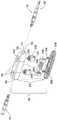
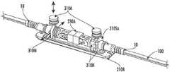
图1是根据所公开用于将一个或多个外部光纤连接器与光纤延长器端口配对的概念的说明性光纤延长器端口的分解图;1 is an exploded view of an illustrative fiber optic extender port in accordance with the disclosed concepts for mating one or more external fiber optic connectors with a fiber optic extender port;
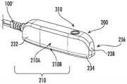
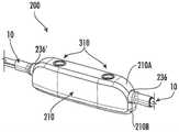
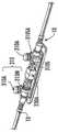
图2是图1的光纤延长器端口的透视图,其中光纤连接器插入并固定在光纤延长器端口的连接端口中;2 is a perspective view of the fiber optic extender port of FIG. 1 with a fiber optic connector inserted and secured in the connection port of the fiber optic extender port;
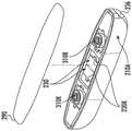
图2A是类似于图1的另一光纤延长器端口的透视图,其中单个光纤连接器插入并固定在连接端口中,以用于与固定到光纤延长器端口的缆带电缆形成光学连接;2A is a perspective view of another fiber optic extender port similar to FIG. 1 with a single fiber optic connector inserted and secured in the connection port for forming an optical connection with a tether cable secured to the fiber optic extender port;
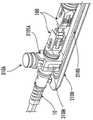
图3描绘了图1的光纤延长器端口的局部分解底视图,其中不包括底部壳体;3 depicts a partially exploded bottom view of the fiber optic extender port of FIG. 1 without the bottom housing;
图4描绘了图3的光纤延长器端口的底部透视组装图,其中底部壳体被移除;4 depicts a bottom perspective assembled view of the fiber optic extender port of FIG. 3 with the bottom housing removed;
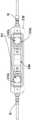
图5是图1的光纤延长器端口的剖视图,其中未附接光纤连接器;5 is a cross-sectional view of the fiber optic extender port of FIG. 1 without a fiber optic connector attached;
图6是图1的光纤延长器端口的底部壳体的透视图,其示出了内部特征;6 is a perspective view of the bottom housing of the fiber optic extender port of FIG. 1 showing internal features;
图7是图1的光纤延长器端口的详细局部剖视图,其中光纤连接器插入到连接端口中;7 is a detailed partial cross-sectional view of the fiber optic extender port of FIG. 1 with the fiber optic connector inserted into the connection port;
图8是图1的光纤延长器端口的剖视图,其示出了与第二光纤连接器配对的第一光纤连接器,所述第一光纤连接器和所述第二光纤连接器插入并固定在相应连接端口中;8 is a cross-sectional view of the fiber optic extender port of FIG. 1 showing a first fiber optic connector mated with a second fiber optic connector inserted and secured in the in the corresponding connection port;
图9是图8的光纤延长器端口的详细剖视图;9 is a detailed cross-sectional view of the fiber optic extender port of FIG. 8;
图10至图12是图1的光纤延长器端口的固定特征的各种透视图;10-12 are various perspective views of the securing features of the fiber optic extender port of FIG. 1;
图13是根据所公开用于将光纤连接器配对的概念的使用具有两个锁定特征的单个固定特征的另一说明性光纤延长器端口的分解图;13 is an exploded view of another illustrative fiber optic extender port using a single securing feature with two locking features in accordance with the disclosed concepts for mating fiber optic connectors;
图14描绘了图13的光纤延长器端口的局部分解底视图;Figure 14 depicts a partially exploded bottom view of the fiber optic extender port of Figure 13;
图15描绘了图14的光纤延长器端口的底部透视组装图,其中底部壳体被移除;15 depicts a bottom perspective assembled view of the fiber optic extender port of FIG. 14 with the bottom housing removed;
图16是图13的光纤延长器端口的顶部透视组装图,其中顶部壳体被移除;16 is a top perspective assembled view of the fiber optic extender port of FIG. 13 with the top housing removed;
图17是图13的光纤延长器端口的透视组装图,其中光纤连接器插入并固定在相应连接端口中并且一起光学配对;17 is a perspective assembled view of the fiber optic extender port of FIG. 13 with the fiber optic connectors inserted and secured in the respective connection ports and optically mated together;
图18是根据所公开的用于将光纤连接器配对的概念的又一说明性光纤延长器端口的透视图;18 is a perspective view of yet another illustrative fiber optic extender port in accordance with the disclosed concepts for mating fiber optic connectors;
图19是图18的光纤延长器端口的顶部透视组装图,其中顶部壳体被移除;Figure 19 is a top perspective assembled view of the fiber optic extender port of Figure 18 with the top housing removed;
图20是安装在图18和图19的光纤延长器端口中的固定特征的透视图,其中光纤连接器附接有适配器组件并且顶部壳体被移除以用于说明目的;20 is a perspective view of a securing feature installed in the fiber optic extender port of FIGS. 18 and 19 with the fiber optic connector attached with the adapter assembly and the top housing removed for illustration purposes;
图21是图18和图19的光纤延长器端口的透视图,其中外壳部分从左侧上的固定特征移除,示出了固定构件接合光纤连接器;21 is a perspective view of the fiber optic extender port of FIGS. 18 and 19 with the housing portion removed from the securing feature on the left side, showing the securing member engaging the fiber optic connector;
图22是图18和图19的光纤延长器端口的顶视图,其中顶部壳体被移除并且光纤连接器固定并配合在适配器组件内;22 is a top view of the fiber optic extender port of FIGS. 18 and 19 with the top housing removed and the fiber optic connector secured and fitted within the adapter assembly;
图23是图18和图19的光纤延长器端口的侧视图,其中外壳部分从两侧上的固定特征移除,以用于示出固定构件接合光纤连接器;Fig. 23 is a side view of the fiber optic extender port of Figs. 18 and 19 with the housing portion removed from the securing features on both sides for showing the securing member engaging the fiber optic connector;
图24是光纤延长器端口的详细透视图,其中外壳部分中的一个围绕固定特征设置并且一个外壳部分被移除,以用于示出外壳和固定构件在光纤延长器端口中的对准;Figure 24 is a detailed perspective view of the fiber optic extender port with one of the housing portions disposed around the securing feature and one housing portion removed for illustrating the alignment of the housing and securing member in the fiber optic extender port;
图25至图27是图18的光纤延长器端口的固定特征的各种透视图;25-27 are various perspective views of the securing features of the fiber optic extender port of FIG. 18;
图28是用于形成图18至图24的光纤延长器端口的固定特征的固定构件的说明性固定构件坯件的透视图;28 is a perspective view of an illustrative securing member blank of a securing member used to form securing features of the fiber optic extender port of FIGS. 18-24;
图29是示出由图28的固定构件坯件形成的固定构件的透视图,其示出固定构件的细节;Figure 29 is a perspective view showing a securing member formed from the securing member blank of Figure 28 showing details of the securing member;
图30和图31是用于与光纤延长器端口一起使用的另一说明性多部件固定特征的视图;30 and 31 are views of another illustrative multi-component securing feature for use with fiber optic extender ports;
图32是用于与光纤延长器端口一起使用的另一说明性多部件固定特征的前视图;32 is a front view of another illustrative multi-component securing feature for use with fiber optic extender ports;
图33和图34分别描绘了用于将多个光纤延长器端口保持成阵列的组织器和安装有光纤延长器端口的组织器的透视图;Figures 33 and 34 depict perspective views of an organizer for holding a plurality of fiber optic extender ports in an array and an organizer with fiber optic extender ports installed, respectively;
图35和图36分别描绘了用于将多个光纤延长器端口保持成阵列的另一组织器和安装有光纤延长器端口的组织器的透视图;并且Figures 35 and 36 depict perspective views of another organizer for maintaining a plurality of fiber optic extender ports in an array and an organizer with fiber optic extender ports installed, respectively; and
图37和图38分别描绘了用于将多个光纤延长器端口保持成阵列的又一组织器和安装有光纤延长器端口的组织器的透视图。37 and 38 depict perspective views of yet another organizer for holding a plurality of fiber optic extender ports in an array and an organizer with fiber optic extender ports installed, respectively.
具体实施方式Detailed ways
现在将详细参考本公开的实施方案,所述实施方案的实例在附图中示出。只要有可能,将使用相同的附图标号指代相同的部件或零件。Reference will now be made in detail to the embodiments of the present disclosure, examples of which are illustrated in the accompanying drawings. Wherever possible, the same reference numbers will be used to refer to the same components or parts.
本文所公开的装置的概念适于根据需要为室内、室外或其他环境提供至少一个光学连接。大体来说,示例性实施方案中所公开和解释的装置是延长器端口,但所公开的概念可视情况与任何合适的装置一起使用。如本文所用,术语“延长器端口”意指包括第一连接端口以用于接收光纤连接器并形成光学连接的任何装置。在一个实施方案中,延长器端口具有第一连接端口和第二连接端口,所述第一连接端口和第二连接端口对准以用于在两个外部光纤连接器之间形成光学连接。因此,延长器端口可用于通过使用通过延长器端口连接的两条电缆来定制或延长光链路的长度,从而为网络提供商提供进一步的灵活性。在其他实施方案中,延长器端口可固定到用于与外部连接器进行光学连接的缆带电缆。连接端口还具有与至少一个连接端口相关联以用于固定和释放光纤连接器的固定特征。以举例的方式,延长器端口还可包括其他部件,诸如有源部件,诸如具有设置在延长器端口的壳体内的用于发送或接收信号的电子器件的无线子组件装置。The concepts of the devices disclosed herein are suitable for providing at least one optical connection for indoor, outdoor or other environments as desired. Generally, the devices disclosed and explained in the exemplary embodiments are extender ports, although the disclosed concepts may be used with any suitable device as appropriate. As used herein, the term "extender port" means any device that includes a first connection port for receiving a fiber optic connector and forming an optical connection. In one embodiment, the extender port has a first connection port and a second connection port aligned for forming an optical connection between two external fiber optic connectors. Therefore, the extender port can be used to customize or extend the length of the optical link by using two cables connected through the extender port, providing further flexibility for the network provider. In other embodiments, the extender port can be secured to a tether cable for optical connection with an external connector. The connection ports also have securing features associated with the at least one connection port for securing and releasing the fiber optic connector. By way of example, the extender port may also include other components, such as active components, such as a wireless subassembly device having electronics disposed within a housing of the extender port for sending or receiving signals.
所公开的概念有利地允许用于延长器端口的紧凑的形状因数,并且还可任选地包括至少一个连接端口,所述至少一个连接端口包括键接部分,以用于将光纤连接器与同所述连接端口相关联的固定特征对准。尽管示出和描述了用于单个直列式连接的延长器端口,但是所述概念可以多种布置或构造扩展到单个装置上的许多直列式连接端口。本文所公开用于装置的固定特征直接与连接器的一部分接合,而无需像需要转动联接螺母、卡口等的现有技术装置的常规结构。如本文所用,“固定特征”不包括螺纹和与连接器上的卡口配合的特征。因此,所公开装置可允许连接端口呈密集的并可产生小型装置,因为不需要转动螺纹联接螺母或卡口所需的空间和结构。紧凑的形状因数可允许将装置放置在室内应用、室外应用、填埋式应用、空中应用、工业或其他应用中的狭窄空间中,同时有利地提供具有至少一个连接端口的装置,其中所述至少一个连接端口具有以可移除且可替换方式进行的牢固且可靠的光学连接。所公开的装置还可以是美观的。组织器也可与延长器端口一起使用,以用于提供具有光学连接的延长器端口阵列的组织。The disclosed concept advantageously allows for a compact form factor for the extender port, and may also optionally include at least one connection port including a keyed portion for attaching the fiber optic connector to the same connector. The attachment features associated with the connection ports are aligned. Although an extender port for a single in-line connection is shown and described, the concepts can be extended to many in-line connection ports on a single device in various arrangements or configurations. The securing features disclosed herein for devices engage directly with a portion of the connector without the need for conventional structures of prior art devices that require turning of coupling nuts, bayonets, and the like. As used herein, "retaining feature" excludes threads and features that mate with bayonet on the connector. Thus, the disclosed device may allow the connection ports to be dense and may result in a compact device since the space and structure required to turn a threaded coupling nut or bayonet is not required. The compact form factor may allow the device to be placed in confined spaces in indoor applications, outdoor applications, landfill applications, aerial applications, industrial or other applications, while advantageously providing the device with at least one connection port, wherein the at least One connection port has a secure and reliable optical connection in a removable and replaceable manner. The disclosed devices may also be aesthetically pleasing. Organizers can also be used with extender ports for providing tissue with an array of optically connected extender ports.
所公开的装置在其设计上是简单且优雅的。所公开装置包括至少一个连接端口以及与所述连接端口相关联的适合于保持由所述连接端口接收的外部光纤连接器的固定特征。连接端口的键接部分可与互补的外部光纤连接器上的键配合,以通过阻止非顺应性的连接器插入来阻止对连接端口的损坏,同时还确保正确的旋转对准以固定光纤连接器。所述键接部分还可在将连接器盲插入装置的连接端口中期间辅助用户在视线不可能或不适合对准时确定相对于的连接端口的正确旋转取向。键接部分可以是连接端口通路233的原始几何圆形形状的附加的键接部分,诸如凸键。然而,装置的连接端口236的概念也可被修改用于没有键接部分的不同连接器设计。The disclosed device is simple and elegant in its design. The disclosed apparatus includes at least one connection port and a securing feature associated with the connection port adapted to retain an external fiber optic connector received by the connection port. The keyed portion of the connection port mates with the key on the complementary external fiber optic connector to prevent damage to the connection port by preventing non-compliant connector insertion, while also ensuring correct rotational alignment to secure the fiber optic connector . The keyed portion may also assist the user in determining the correct rotational orientation relative to the connection port during blind insertion of the connector into the connection port of the device when line of sight is impossible or unsuitable for alignment. The keyed portion may be an additional keyed portion of the original geometric circular shape of the
所公开概念通过在无需考虑转动用于保持外部光纤连接器的螺纹联接螺母或卡口的空间的情况下将光纤连接器直接插入装置的连接端口中而有利地实现快速简单的连接和固位。大体来说,所公开用于与本文延长器端口一起使用的固定特征可包括一个或多个部件,其中至少一个部件平移以用于将外部光纤连接器释放或固定到装置。具体地,固定特征能够在壳体内平移。如本文所用,术语“固定特征”不包括用于固定设置在连接器上的卡口的螺纹部分或特征。The disclosed concept advantageously enables quick and easy connection and retention by inserting the fiber optic connector directly into the connection port of the device without considering the space to turn the threaded coupling nut or bayonet used to hold the external fiber optic connector. In general, the securing features disclosed for use with extender ports herein may include one or more components, at least one of which translates for releasing or securing an external fiber optic connector to a device. Specifically, the securing feature is capable of translation within the housing. As used herein, the term "retaining feature" does not include a threaded portion or feature for securing a bayonet provided on a connector.
由于与所公开装置一起使用的连接器占有面积并不要求联接螺母或卡口的蓬松度,因此与所公开的装置一起使用的光纤连接器也可显著小于常规的光纤连接器。Fiber optic connectors for use with the disclosed devices can also be significantly smaller than conventional fiber optic connectors because the connector footprint used with the disclosed devices does not require the bulkiness of the coupling nut or bayonet.
所公开装置包括用于直接与外部光纤连接器的连接器外壳的合适部分接合的固定特征等,以用于将光学连接部与装置固定在一起。下文更详细地论述概念的不同变型。用于将光纤连接器固定在所公开装置中的特征允许装置和光纤连接器两者以及快速连接特征的小得多的占有面积。尽管显示为单一装置,但是所述装置还可在壳体内具有密集的连接端口间距(诸如双工设计),或者如果需要可具有更宽的间距。有利地,所公开装置允许以相对较小的形状因数的可扩展并且相对密集且有组织的连接端口阵列,同时对于要求苛刻的环境仍然是坚固的。The disclosed device includes securing features and the like for directly engaging a suitable portion of a connector housing of an external fiber optic connector for securing the optical connection with the device. Different variations of the concepts are discussed in more detail below. The features used to secure the fiber optic connector in the disclosed device allow for a much smaller footprint of both the device and the fiber optic connector as well as the quick connect feature. Although shown as a single device, the device may also have dense connection port spacing within the housing (such as a duplex design), or wider spacing if desired. Advantageously, the disclosed device allows for a scalable and relatively dense and organized array of connection ports in a relatively small form factor, while still being robust to demanding environments.
本文所公开概念适合于诸如用于光纤入户应用或5G应用的光学分配网络,但同样也适用于其他光学应用,包括室内应用、汽车应用、无线应用或其他合适的应用。另外,所公开概念可以与装置的固定特征配合的任何合适的光纤连接器占有面积来使用。装置的各种设计、构造或特征如本文所论述更详细地公开并且可根据需要进行修改或改变。The concepts disclosed herein are suitable for optical distribution networks, such as for fiber-to-the-home applications or 5G applications, but are equally applicable to other optical applications, including indoor applications, automotive applications, wireless applications, or other suitable applications. Additionally, the disclosed concepts may be used with any suitable fiber optic connector footprint that mates with the securing features of the device. Various designs, configurations or features of the device are disclosed in greater detail as discussed herein and may be modified or changed as desired.
图1是说明性延长器端口200的分解图,所述延长器端口200包括用于形成光学连接的至少一个连接端口236。一般来讲,延长器端口200包括至少一个连接端口236,所述连接端口236是装置的壳体210的一部分。以说明的方式,至少一个连接端口236被模制为壳体210的一部分。FIG. 1 is an exploded view of an
一般来讲,延长器端口200包括壳体210,所述壳体210包括主体232和设置在延长器端口200的第一端部或部分212上的一个或多个连接端口236。连接端口236被配置用于接收和保持诸如图2所示的外部光纤连接器10,以在延长器端口200内形成一个或多个光学连接。在图1的实施方案中,从延长器端口200的每一端接收光纤连接器10,以用于在装置内在光纤连接器10之间形成光学连接。尽管示出了单光纤连接器10,但是所述概念也可与多光纤连接器一起使用。Generally speaking, the
图1的延长器端口200包括第一连接端口236和第二连接端口236’,它们成直列式或对准以在从延长器端口200的相应端部插入的光纤连接器10之间形成光学连接。在其他实施方案中,延长器端口可在一个端部上具有固定电缆100和用于与固定电缆的光纤形成光学连接的单个连接器端口236,诸如图2A所示。The
连接端口236各自包括相应的光学连接器开口238,所述光学连接器开口238从延长器端口200的外表面234延伸到延长器端口200的腔体216中并且限定连接端口通路233。至少一个固定特征310与连接端口通路233相关联,以用于与外部光纤连接器10配合。固定特征可平移以用于释放或固定外部光纤连接器10。诸如图1所示的一个或多个相应的固定特征通路245从延长器端口200的外表面234延伸,并且与延长器端口200的相应连接端口通路233配合。相应固定特征310与连接端口通路233相关联,并且可以使固定特征310的一部分设置在延长器端口200的固定特征通路245的一部分内。The
通过根据需要将一个或多个合适的外部光纤连接器10插入相应连接端口通路233中来与延长器端口200形成光学连接。具体地,连接端口通路233被配置用于接收光纤电缆组件100(下文称为电缆组件)的合适的外部光纤连接器10(下文称为连接器)。每个连接端口通路233与固定特征310相关联,以用于将连接器10保持(例如,固定)在延长器端口200中。固定特征310有利地允许用户通过将连接器10推入端口中直至它被固定来在延长器端口200的连接端口236处形成快速且容易的光学连接。固定特征310可在诸如通过向下推动被致动时操作用于提供连接器释放特征。Optical connections to
具体地,如图2所示,通过推动连接器10并且使其完全安置在连接端口236内,可将连接器10保持在装置的相应连接端口236内。为了从相应连接端口236释放连接器10,通过向下推动来致动固定特征310以将固定特征310平移合适的距离,从而从连接器外壳释放固定特征并允许将连接器从连接端口236移除。换句话讲,至少一个固定特征310能够在于固定特征通路245的一部分内平移时释放连接器10。连接器10的完全插入和自动固位可通过仅将连接器推入连接端口236中而有利地允许单手安装连接器10。所公开的延长器端口200在完全插入时通过将固定特征偏置到保持位置来实现此连接器固位特征。然而,根据所公开的概念,用于保持和释放连接器10的其他操作模式也是可能的。例如,固定特征310可被设计来需要为了插入连接器10而致动;然而,这可能需要双手操作。Specifically, as shown in FIG. 2, by pushing the
固定特征310可被设计用于保持针对连接器10的最小拉出力。在一些实施方案中,可选择拉出力以在对装置或连接器10造成损坏之前释放连接器10。以举例的方式,在连接器10释放之前,与连接端口236相关联的固定特征310可能需要约50磅(约220N)的拉出力。同样,固定特征310可针对连接器10提供侧向拉出力,以同样防止损坏。以举例的方式,在连接器10释放之前,与连接端口236相关联的固定特征310可提供约25磅(约110N)的侧向拉出力。当然,诸如75磅(约330N)或100磅(约440N)的其他拉出力以及其他侧向拉出力也是可能的。The securing
本文所公开的固定特征310可采取许多不同的构造或配置。以说明的方式,固定特征310可由如图1所示的单个部件或如图19所示的多个部件形成。此外,固定特征310或固定特征310的部分可被构造为诸如图19所示的子组件,以便于组装。其他变型仍是可能的。图13描绘了具有与配对连接端口236配合的相对锁定特征的单个固定特征310M。The securing features 310 disclosed herein may take on many different configurations or configurations. By way of illustration, the securing
一般来讲,延长器端口200包括由延伸到延长器端口200的腔体216中的光学连接器开口238限定的至少一个连接端口236以及与连接端口236相关联的固定特征310。Generally speaking, the
更具体地,图1是延长器端口200的分解图,所述延长器端口200包括设置在延长器端口200上的至少一个连接端口236,其中连接端口236由从延长器端口200的外表面234延伸到延长器端口200的腔体216中并且限定连接端口通路233的光学连接器开口238限定。延长器端口还包括用于接收固定特征310的至少一部分的至少一个固定特征通路245。固定特征310使用相应弹性构件310R偏置到保持位置。固定特征通路245从延长器端口200的外表面234延伸。延长器端口200包括具有第一部分210A和第二部分210B的壳体210以及适配器组件230A。More specifically, FIG. 1 is an exploded view of an
图1描绘了连接器10,其在延长器端口200的相对端部处对准以插入相应连接端口236中,并且图2描绘了多个连接器10,其保持在组装的延长器端口200的相应连接端口236内。如图2A所示,根据所公开的概念,延长器端口200可具有附接在一个端部处的固定缆带电缆100和另一端部处的用于接收连接器10的配对光学连接端口236。FIG. 1 depicts
以说明的方式,一个或多个连接端口236和一个或多个固定特征通路245是壳体210的一部分。说明性地,图1和图2描绘了延长器端口200,其包括壳体210,所述壳体210包括主体232,所述主体232具有设置在第一端部或部分212上的第一连接端口236和设置在相对端部上的第二连接端口236’。每个连接端口236、236’包括相应的光学连接器开口238。光学连接器开口从延长器端口200的壳体210的外表面234延伸到腔体216中,并且限定相应连接端口通路233、233’。一个或多个相应固定特征通路245从壳体210的外表面234延伸以与相应连接端口通路233、233’配合。第二连接端口通路(233’)与第一连接端口通路(233)对准,使得相应外部连接器10可使用延长器端口200进行光学配对。如图1所描绘的,壳体210由第一部分210A和第二部分210B形成,但是壳体210的其他布置也是可能的。By way of illustration, one or
图3是示出从第一部分210A移除的壳体210的第二部分210B并且示出延长器端口200的内部组件的分解图。图3和图4示出了图1的延长器端口200的组件。图5示出了穿过没有附接连接器的组装的延长器端口200的连接端口通路233的纵向横截面。FIG. 3 is an exploded view showing the
如图5所示,固定特征310被偏置到保持位置。具体地,固定特征310使用定位在固定特征310与壳体210之间的固定特征弹性构件310R沿向上的方向进行偏置。因此,固定特征310的一部分能够在固定特征通路245的一部分内平移。如所描绘的,密封特征310S设置在固定特征310上。密封部件310S在固定特征310与固定特征通路245之间提供密封,以防止灰尘、粉尘和碎屑进入装置。As shown in FIG. 5, the securing
如图5最佳描绘的,此连接端口通路233可包括键接部分233KP作为延长器端口200的一部分。如图所示,键接部分233KP在进入连接端口通路233之后在通道中设置在固定特征310的前方(即,之前)。键接部分233KP可在连接端口通路233中在固定特征前方具有任何合适的位置。如所描绘的,延长器端口200具有与每个连接端口通路233相关联的固定特征310,所述固定特征310与固定特征通路245的一部分配合。在此实施方案中,固定特征310是形成为具有锁定特征310L的单个部件的按钮致动器。As best depicted in FIG. 5 , this
延长器端口还可具有设置在固定特征310的光学连接器开口238一侧的键接部分233KP。键接部分233KP阻止非顺应性的连接器插入连接端口236中,从而防止可能对装置造成的损坏。合适的连接器10具有与延长器端口200的键接部分233KP配合的互补的键接特征。键接部分233KP可以是在固定特征310的光学连接器开口238一侧设置在连接端口通路233内的突出部或附加特征,并且如果使用的话可采取若干不同的配置。例如,键接部分233KP可以是如图所示的简单突出部。在其他实施方案中,键接部分233KP可呈D形开口的形状,以允许仅具有互补特征的合适的连接器10插入连接端口236中。键接部分233KP还可帮助将连接器10盲配对到连接端口236中,因为它仅允许在连接器处于正确旋转取向时进一步插入连接端口236中。The extender port may also have a keyed portion 233KP disposed on the side of the
图1的延长器端口200还包括至少一个适配器组件230A,其在组装时与相应连接端口236中的一者或多者对准。适配器组件230A适于对准插入连接端口236中的连接器10的相应套接管。如图1和图3所示,适配器组件230A可包括套接管套筒230FS、由一个或多个部件230H形成的适配器外壳和弹性构件230R。套接管套筒230FS接收连接器10的相应套接管10F的一部分以用于精确对准。The
图3和图4描绘了图1的延长器端口200的组件。图3描绘了固定特征310,其被对准以安装到壳体210的第一部分210A的固定特征通路245中。如所描绘的,固定特征310的键接特征310K(图10至图12)与固定特征通路245的特征对准,其针对锁定特征310L在延长器端口200中的正确取向仅允许以一种取向进行组装。图3还以分解图的形式示出了在对准并安装到壳体210的第一部分210A的鞍座210D中之前的适配器230A。在安置时,适配器230A的弹性构件230R将外壳210H部件向外偏置,并且为套接管套筒230FS或适配器230A提供相对于壳体210“浮动”的能力。“浮动”是指适配器230A可在X-Y平面中具有轻微移动以用于对准,并且可防止沿着连接器插入的轴线在Z方向上过度行进,使得可在配对的连接器之间进行合适的对准。当适配器230A安装到第一部分210A中时,外壳部件230H上的偏置力将适配器230A固定就位,直到如图5所示附接了壳体210的第二部分210B。3 and 4 depict components of the
在其他实施方案中,适配器230A可由若干部件形成,但是一些适配器或其部分也可与延长器端口一体形成。In other embodiments, the
图4描绘了延长器端口200的局部组装图,其示出安装到壳体210的第一部分210A中的适配器230A,并且在壳体210的第二部分210B被附接以将固定特征弹性构件310R捕获就位之前放置在固定特征310的底部部分上的相应固定特征弹性构件310R。固定特征310可具有底部凹陷部310BR或环,所述底部凹陷部310BR或环用于使固定特征弹性构件310R安置在固定特征310上并使恢复力集中在固定特征310上,如图5中最佳所示。然后,壳体210的第二部分210B可使用或不使用密封元件290以合适的方式附接到第一部分210A。4 depicts a partially assembled view of
在此实施方案中,固定特征310包括孔310B,所述孔310B在组装时与至少一个连接端口通路233对准,如图5中最佳所示。孔310B被设定大小以用于穿过其接收合适的连接器10,以固定所述连接器来进行光学连接。穿过固定特征310的孔或开口可具有用于与其相应的连接器配合的任何合适的形状或几何形状。如本文所用,孔可具有任何期望的合适的形状,包括在孔的表面上的用于与连接器接合以固定所述连接器的特征。In this embodiment, the securing
在一些实施方案中,固定特征310能够在将合适的连接器10插入连接端口通路233中时移动到打开位置。当连接器10完全插入连接器端口通路233中时,固定特征310能够自动移动到保持位置。因此,连接器10通过固定特征310固定在连接端口236内,而无需像现有技术装置那样转动联接螺母或卡口。换句话讲,当将合适的连接器10插入连接端口236中时,固定特征310从保持位置平移到打开位置。然后,当连接器10完全安置时,固定特征310偏置回保持位置,以将连接器10固定在连接端口236中。固定特征通路245横向于延长器端口200的纵向轴线LA布置,但是其他布置也是可能的。其他固定特征可以类似的方式操作,但是使用开口而不是穿过其接收连接器的孔。In some embodiments, the securing
如图5所示,固定特征310包括锁定特征310L。锁定特征310L在连接器10的一部分完全插入连接端口236中时与连接器10的一部分配合以固定所述连接器。具体地,连接器10的连接器外壳20可具有接合固定特征310的锁定特征310L的配合几何形状。在此实施方案中,固定特征310包括孔310B,孔310B在组装时如图5所示分别与相应连接器端口通路233对准。孔310B被设定大小以用于穿过其接收连接器10的一部分。图7至图9是延长器端口200的纵向剖视图,其描绘延长器端口200的光学连接端口236,其中连接器10保持在其中。As shown in FIG. 5, the securing
如此实施方案中所描绘的,锁定特征310L设置在孔310B内。具体地,在此实施方案中,锁定特征310L包括斜坡。斜坡在孔310B的一部分处一体形成,其中斜坡在看向连接端口236中时向上成角度。如图所示,斜坡允许连接器10在连接器10插入连接端口236中时抵靠固定特征弹性构件310R向下推动并平移固定特征310。斜坡可具有任何合适的几何形状,诸如固位表面(诸如在背面处的台肩),或者斜坡可通向在固位表面之前的平坦部分。当固定特征310的锁定特征310L与连接器10的锁定特征20L的配合几何形状对准时,固定特征310平移,使得锁定特征310L接合连接器10的锁定特征20L接合,如图7至图9所示。在图10至图12中示出了图1的固定特征310的详细视图。As depicted in this embodiment, locking
壳体210的部件之间的密封可包括设置在部件之间的密封元件(不可见的)。密封可包括在壳体的一部分中的凹槽,所述凹槽与壳体210的另一部分上的舌形件配合。凹槽可围绕密封表面的周边延伸。凹槽可接收一个或多个适当大小的O形环或垫圈,以使延长器端口200抗风化。O形环被合适地设定大小以用于在壳体210的部件之间形成密封。以举例的方式,合适的O形环可以是压缩O形环以用于维持抗风化密封。其他实施方案可使用粘合剂或材料的合适焊接(诸如利用适当材料的超声或感应焊接)以密封延长器端口200。The sealing between the components of the
图6描绘了透视图,其示出了图1的壳体210的第二部分210B的细节。壳体210的第二部分210B包括设置在固定构件凹坑210SP内的至少一个销210P。销210P和固定构件凹坑210SP配合以使弹性构件310R对准并安置在壳体210的第二部分210B与固定构件310之间,以将固定构件310偏置到保持位置。FIG. 6 depicts a perspective view showing details of the
在此实施方案中,壳体210B还包括在外周边附近的舌形件210T,所述舌形件210T可与壳体210的第一部分210A上的凹槽210G的构造配合以用于装置的对准和/或密封。壳体的部件之间的接口可具有用于固定或密封部件的其他结构或特征,诸如用于固定壳体的部件的紧固件或用于密封的粘合剂、O形环或垫圈或可焊接特征。壳体210可根据需要具有任何合适的形状、设计或配置。壳体210可包括至少一个肋部或支撑件210S,从而为延长器端口200提供挤压支撑并从而形成牢固的结构。此外,如果需要,壳体210可包括多于两个的部分。同样,壳体210的多个部分可包括连接端口236。In this embodiment, the
本文所公开的延长器端口200中的任一者均可通过使用诸如垫圈、O形环、粘合剂、密封剂、焊接、包覆成型等的任何合适的手段将壳体210的接缝适当地密封在部件之间而任选地是抗风化的。此外,连接端口236与防尘帽或连接器10之间的界面可使用适当的几何形状和/或连接器或防尘帽上的密封元件(诸如O形环或垫圈65)来密封。如果延长器端口200意图用于室内应用,则可能不需要抗风化。Any of the
延长器端口200还可包括集成的安装特征。以说明的方式,壳体210可具有被配置为设置在侧面上的通路的安装特征。因此,用户可简单地使用穿过这些侧向通路的诸如束线带的紧固件来根据需要将延长器端口200安装到墙壁或杆。
如图9所示,连接器10的套接管10F之间的连接器配对平面230MP设置在延长器端口200的腔体216内。连接器10包括位于外壳20上的锁定特征20L,所述锁定特征20L用于与延长器端口200的固定特征310配合。另外,连接端口236、236’包括与连接端口236、236’相关联的锁定特征310之间的合适的长度L,使得连接器10可具有用于合适的光学性能的适当量的“浮动”。连接器10可包括至少一个O形环65以用于在连接器10完全插入连接端口236中时在密封表面233SS处密封连接器端口通路233。说明性地,连接端口236具有用于连接器10的连接端口通路密封表面233CS,所述连接端口通路密封表面233CS设置在距连接器10的配对平面230MP的距离D3处。距离D3比固定特征310的锁定特征310L更远离配对平面230MP。应当对距离L内的锁定特征310L之间的部件公差叠加进行管理,以与配对的套接管实现合适的连接器到连接器交接。As shown in FIG. 9 , the connector mating plane 230MP between the
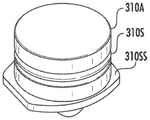
图10至图12描绘了由图1的说明性装置示出的固定特征310的详细透视图。锁定特征310L包括固位表面310RS。在此实施方案中,锁定特征310L的斜坡的背面形成与连接器10的连接器外壳20上的互补几何形状配合的台肩。然而,固位表面310RS可具有配合用于固定连接器10以形成期望机械固位的不同表面或边缘。例如,固位表面310RS可进行倾斜或具有垂直壁以调节连接端口236的拉出力。然而,固位表面310RS的其他几何形状也是可能的。另外,连接端口236在与连接器10的连接端口通路密封表面处具有密封位置,所述密封位置比固定特征310或锁定特征310L更靠近外表面234处的光学连接器开口238。10-12 depict detailed perspective views of the securing
固定特征310还可包括如图10至图12中最佳描绘的其他特征。例如,固定特征310可包括密封构件310S,所述密封构件310S设置在连接器端口通路233上方以将灰尘、碎屑等保持在延长器端口200的部分之外。密封构件310S的大小针对固定特征310和固定特征通路245中的固位凹槽310RG设定以用于密封。The securing features 310 may also include other features as best depicted in FIGS. 10-12 . For example, the securing
固定特征310还可包括一个或多个引导件310G,所述一个或多个引导件310G与壳体210配合,以在平移期间将孔310B保持在相应固定特征通路245内的正确旋转取向上。在此实施方案中,两个引导件310G以大约180度的间隔布置并且引导固定特征310的平移。固定特征310还可包括一个或多个键310K,所述一个或多个键310K与壳体210或连接端口插入件230配合,以仅允许到壳体210或连接端口插入件230中的一个组装取向,从而相对于连接器插入方向将锁定特征310L保持在相应固定特征通路245内的正确位置中。The securing
固定特征310还可包括止动表面310SS,以用于阻止越程或者阻止固定特征310在组装时从延长器端口200移除。在此实施方案中,止动表面310SS被设置为引导件310G的顶表面。固定特征310还可包括浅坑310G或其他特征,以用于阻止固定特征310的无意启动/平移或实现用户的战术感。固定特征310还可以是不同的颜色或具有标记记号以用于识别端口类型。The securing
如图10和图11最佳所示,锁定特征310L被配置为斜坡310RP,所述斜坡310RP延伸到短的平坦部分、然后延伸到恢复到圆形横截面的台肩,以形成固位表面310RS以用于一旦连接器10完全插入连接端口236的连接器端口通路233中就接合并保持连接器10。因此,固定特征310能够在将合适的连接器10插入连接器端口通路233中时移动到打开位置(OP),因为连接器外壳20接合斜坡310RP,从而在插入期间向下推动固定特征。As best shown in FIGS. 10 and 11 , the
当将合适的连接器10插入连接端口236中时,固定特征310从保持位置(RP)平移到打开位置(OP)。当连接器10完全插入连接器通路233中时,固定特征310自动移动到保持位置(RP),因为它被向上偏置到保持位置。这有利地允许连接器10与延长器端口200的即插即用连接,而不必像常规装置一样转动联接螺母或卡口。因此,可更快速地且相对容易地在可能不便的位置与延长器端口形成连接。When the
其他类型的固定构件310也可以类似方式操作以固定连接器10,但是包括多于一个的部件,诸如与固定构件310M配合的致动器310A,诸如在本文中用其他实施方案所公开的。另外,使用多于一个的部件可允许固定特征通路245相对于装置的纵向轴线LA的其他布置。Other types of
为了使用户更容易识别连接端口,可使用标记记号(诸如延长器端口的文本或颜色编码)或对输入缆带进行标记(例如,橙色或绿色聚合物)等。To make it easier for the user to identify the connection ports, marking symbols (such as text or color coding of the extender ports) or the input cable straps (eg, orange or green polymer), etc. may be used.
延长器端口200中的任一个还可具有一个或多个防尘帽(未示出),以用于保护连接端口236免受进入延长器端口或干扰光学性能的灰尘、尘土或碎屑的影响。因此,当用户希望与延长器端口形成光学连接时,移除适当的防尘帽,然后可将电缆组件100的连接器10插入相应连接端口236中,以用于与延长器端口200的形成光学连接。防尘帽可使用与连接器10类似的释放和保持特征。以说明的方式,当向内或向下推动固定特征310时,防尘帽被释放并且可被移除。Any of the
根据所公开的概念,延长器端口200的其他变型是可能的。以举例的方式,图13至图18和图18至图24的延长器端口200类似于图1的延长器端口200,除了它们使用具有固定特征310的其他机构之外。图13至图17描绘了根据所公开的概念的另一说明性光纤延长器端口200。图13至图17的延长器端口200类似于图1的延长器端口200,除了它使用具有相对的锁定特征310L的单个固定构件310M。与多个部件的公差堆叠相比,在图13的固定构件310M的共同基准面上使用两个锁定特征310L提供了对锁定特征310L之间的长度L的更容易控制。单个致动器310A(即,两个)用于与固定构件310M配合以释放连接端口236并将其配对。同图1的延长器端口200一样,弹性构件310R将固定构件310M向上偏置到相应连接端口236的每一个端部处的保持位置,从而为连接端口236提供正常锁定位置。为了释放图13的固定构件310M的锁定特征310L,可向下推动致动器310A中的任一个,以使固定构件310M的一个端部向下平移并且将锁定特征310L移动到释放位置。Other variations of
图13和图14描绘延长器端口200的局部分解图,其示出构造的细节,并且图15示出移除了第二部分210B的组装图。此延长器端口200具有偏置固定特征,所述偏置固定特征以与所公开的其他延长器端口类似的方式操作。然而,此延长器端口200使用具有公共固定构件310M的固定特征310,所述公共固定构件310M包括两个锁定特征310L,以用于避免装置中的多个部件的公差堆叠,从而有助于保持光学性能。参考图13,在公共固定构件310M上的两个锁定特征310L以期望的距离L定位,以实现配对的套接管之间的合适的连接器到连接器接口;并且也可考虑连接器的公差和套接管行进。如图13至图16所描绘的,相对的锁定特征310L模制在公共固定构件310M上。公共固定构件310M的锁定特征310L可具有用于固定连接器的合适的几何形状,如本文所述。13 and 14 depict partially exploded views of
致动器310A与形成为壳体210的第一部分210A的一部分的相应固定特征通路245配合,如本文所讨论的。致动器310A还包括推臂310PA,所述推臂310PA间隔开以允许连接器10的一部分穿过其以进行配对,如图16最佳所示。如图所示,当组装时,推臂310PA接触固定构件310M的邻近锁定特征的部分,并且使致动器310A向下平移将锁定特征310L平移到释放位置。The
类似于图1的延长器端口200,固定特征310可沿竖直方向(如图16中的箭头所示)平移,以将连接器10保持和释放在延长器端口200中。如所描绘的,弹性构件310R设置在固定构件310M下方,以将固定构件310M(和致动器310A)的端部向上偏置到正常保持位置(RP)。固定特征310还包括锁定特征310L。Similar to the
在此实施方案中使用了简化的适配器组件230A,所述适配器组件230A包括在没有弹性构件的情况下设置在适配器外壳230H内的套接管套筒230FS,所述套接管套筒230FS用于在连接器10之间精确对准配对的套接管。图17描绘了完全组装的延长器端口200。A
装置可具有使用多于一个的部件的用于固定特征310的其他构造。说明性地,图18至图24描绘了另一延长器端口200,所述延长器端口200包括作为壳体210的一部分的连接端口236,所述另一延长器端口200具有包括多于一个部件的固定特征310。此延长器端口类似于所描述的构造,并且为简洁起见,对具有包括多于一个的部件的固定特征310的此装置的描述将描述设计上的差异,而其他特征与所公开的特征类似。The device may have other configurations for securing
图18至图24的延长器端口200使用包括致动器310A和固定特征构件310M的固定特征310。具体地,固定特征构件310M包括开口,所述开口可在被推动时(或在将合适的连接器10插入连接端口236中时)通过致动器310A(或其他结构)弹性变形,并且当致动器310A被释放时或当连接器10完全安置在连接端口236内时,固定特征构件310M弹回以接合连接器10的合适的部分,诸如连接器外壳20的锁定特征20L,如将更详细地讨论的。如图29最佳所示,固定构件310M包括由一个或多个臂310AM形成的锁定特征310L。The
图19至图22是局部组装图,其中如下所述移除了固定特征子组件310SA的部分,以用于公开固定特征310的构造和操作。如图19所描绘的,固定构件310M可放置到由一个或多个外壳部分310HH形成的外壳中,以维持壳体210内的固定特征的正确取向。固定特征子组件310SA还允许将固定构件310M更容易地组装到延长器端口200的壳体210中。换句话讲,外壳部分310HH可具有合适的几何形状,以用于将固定构件保持在期望的取向上。图19的右侧描绘了组装并放置到壳体210的第二部分210B中的固定特征子组件310SA。例如,第二部分210B可具有用于安置固定特征子组件310SA的凹坑或其他对准特征。图19的左侧描绘了不具有外壳部分310HH的固定构件310M和致动器310A,以显示与连接器10上的锁定特征的接合。因此,致动器310A与固定特征的相应固定构件310M对准并一起定位。FIGS. 19-22 are partial assembly views with portions of the securing feature subassembly 310SA removed as described below for disclosing the construction and operation of the securing
图20是详细的透视图,其示出了设置在310SA的部件310H内的固定构件310M,并且适配器组件230A被移除以示出连接器10的互补套接管10F的配对。具体地,固定构件310M的臂接合锁定特征20L(例如,凹槽),所述锁定特征20L一体形成在连接器10的外壳20上。图21是类似于图20的详细透视图,但是示出了适配器组件230A。FIG. 20 is a detailed perspective view
固定特征310包括致动器310A和固定构件310M。固定构件310M包括在其臂310AM之间的开口,所述开口可在平移(即,推动)时或当通过将固定构件310M的臂向外伸展(即,平移)将合适的连接器10插入连接端口236中时通过致动器310A弹性变形。当致动器310A被释放或连接器完全安置在连接端口236或输入端口260内时,固定构件310M的臂310AM弹回以接合连接器10的合适的部分(诸如连接器外壳20的锁定特征20L)或将致动器310A移动到正常位置。臂310AM具有边缘部分,所述边缘部分充当合适的连接器10的锁定特征310L。以说明的方式,臂310AM的边缘部分接合连接器外壳20的锁定特征20L,以固定连接器20。为了从连接端口236释放连接器10,向外平移臂310AM和臂310AM上的锁定特征310L。The securing
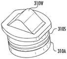
如图27最佳所示,致动器310A包括楔形件310W,所述楔形件310W推动进入固定构件310M的头端310H,从而使固定构件310M的臂310AM向外弹性偏转,以释放连接器10。固定特征310的固定构件310M或致动器310A可包括多种不同的构造。同样,如果需要,包括多于一个的部件的固定特征310可由固定特征弹性构件310RM偏置。例如,固定特征弹性构件310RM可将致动器310A朝向固定位置偏置。在其他实施方案中,固定特征弹性构件可偏置固定构件310M。As best shown in FIG. 27 , the
图25至图27是在图18至图24中示出的延长器端口200的固定特征310的致动器310A的各种透视图。致动器310A可包括密封构件310S,所述密封构件310S设置在连接器端口通路233上方以将灰尘、碎屑等保持在延长器端口200的部分之外。密封构件310S的大小针对致动器310A和固定特征通路245中的固位凹槽310RG设定以用于密封。致动器310A还可被成形为具有一个或多个引导件310G,所述一个或多个引导件310G与壳体210或连接端口插入件230配合,以在平移期间保持楔形件310W在相应固定特征通路245内的正确旋转取向。在此实施方案中,凸缘的形状有助于旋转取向。致动器310A还可包括止动表面310SS,以用于阻止越程或者阻止致动器310A在组装时从延长器端口200移除。致动器310A还可以是不同的颜色或具有标记记号以用于识别端口类型。例如,对于连接端口236,致动器310A可着色为红色,而输入连接端口260的致动器310A可着色为黑色。其他颜色或标记记号方案可用于直通端口、多光纤端口或用于分路信号的端口。25-27 are various perspective views of the
因此,固定特征310的固定特征构件310M适合于将连接器10保持在连接端口236中,如本文所讨论的。对于包括所公开装置的多于一个的部件的固定特征310,其他不同实施方案是可能的。图25至图29是用于说明设计细节的固定构件310M的各种视图。图28是用于形成图29所描绘的固定特征310M的固定构件坯件的透视图。固定构件310M可由诸如弹簧钢的任何合适的材料形成,并且具有用于保持连接器10的合适的几何形状。如所描绘的,固定构件310M包括臂310AM,所述臂310AM限定臂310AM之间的开口(未标号)以及在臂310AM的端部处形成的头端310H。臂310AM之间的开口(未标号)被设定大小以用于与合适的连接器10配合。臂310AM可包括突片310T,所述突片310T是弯曲的,以在插入时有助于连接器10与固定构件310M接合,并且在连接器10插入连接端口236中时允许臂310AM更平滑地向外推动和平移。同样,头端310H也可形成为具有与致动器310A配合的合适的形状。同其他固定特征310一样,固定特征310可包括多于一个的部件,以用于在将合适的连接器10插入连接端口236中时从保持位置(RP)平移到打开位置(OP)。当连接器10完全插入连接器通路233中时,然后固定特征310自动移动到保持位置(RP),因为臂310AM被偏置到保持位置。这有利地允许连接器10与延长器端口200的即插即用连接,而不必像常规装置一样转动联接螺母或卡口。因此,可更快速地且相对容易地在可能不便的位置与延长器端口形成连接。Accordingly, the securing
包括多于一个的部件的固定特征310可具有用于与本文所公开的装置一起使用的各种其他配置。图30和图31描绘了包括用于与致动器310A一起使用的固定构件310M的另一固定特征310的透视图。在此实施方案中,固定构件310M被倒置,使得与其他实施方案相比,头端310H与延长器端口壳体的一部分配合以用于使臂310AM向外平移。更具体地,诸如壳体的连接器端口插入件的延长器端口的一部分包括楔形件,以用于在致动器310A向下平移时使臂310AM向外平移。The securing
图32是包括用于与致动器310A一起使用的固定构件310M的又一固定特征310的前视图,与其他实施方案相比,所述固定特征310提供降低的高度。此固定构件310M包括臂310AM,所述臂310AM限定臂310AM之间的开口(未标号)以及在臂310AM的端部处形成的头端310H。如图32所示,此固定构件310M的头端31OH具有向内且向下弯曲的端部,并且致动器310A将楔形件310W进一步向上定位到致动器310A的占有面积中,从而产生高度降低的构造并且还允许所装置降低其高度。32 is a front view of yet another securing
所公开的概念的其他变型是可能的。固定特征310可具有用于接合连接器10的任何合适的取向或构造。固定特征310可相对于连接端口236的纵向轴线LA成角度布置。以举例的方式,固定特征310可包括设置在固定特征通路245中的固定构件310M和致动器310A,所述固定特征通路245相对于连接端口236的纵向轴线LA成角度。同样,连接器10具有连接器外壳20,所述连接器外壳20具有相对于连接器的纵向轴线成角度的锁定特征20L。类似的概念可与壳体或连接端口插入件的一部分以及整体式固定特征310一起使用。Other variations of the disclosed concepts are possible. The securing
将延长器端口200组织成阵列可能是有利的。图33描绘了包括通路400P和一个或多个引导件400G的组织器400。组织器400被设定大小以用于接收多个延长器端口200,以提供如图34所示的装置阵列的组织。延长器端口200在通路400P中对准并且与组织器400具有摩擦配合。It may be advantageous to organize
组织器400可具有多种形状和配置。图35描绘了另一组织器400,其包括设置在公共壁的相反侧上的分离的通路400P。通路400P具有开放侧420,并且公共壁的端部具有卡扣配合特征400S,以用于将延长器端口200固定到组织器400,如图36所示。
图37描绘了包括具有开放侧420的通路400P的又一组织器400。组织器400包括用于将延长器端口200固定到组织器400的卡扣配合特征400S,如图38所示。FIG. 37 depicts yet another
本申请还公开了用于制造延长器端口的方法。一种制造延长器端口的方法包括提供壳体210,所述壳体210包括第一连接端口236,所述第一连接端口236具有光学连接器开口238和连接端口通路233。所述方法包括:组装至少一个固定特征,使得它与壳体固定的连接端口通路相关联;以及安装至少一个固定特征弹性构件,以用于偏置至少一个固定特征的一部分。还设想了用于制造如本文所公开的诸如延长器端口200的装置的其他方法。The present application also discloses methods for making extender ports. One method of making an extender port includes providing a
另一方法包括为壳体提供:第一连接端口,所述第一连接端口包括从所述延长器端口的外表面延伸到所述延长器端口的腔体中并且限定第一连接端口通路的光学连接器开口;以及第二连接端口,所述第二连接端口包括从所述延长器端口的外表面延伸到所述延长器端口的腔体中并且限定第二连接端口通路的光学连接器开口,其中所述第二连接端口通路与所述第一连接端口通路对准。所述方法包括:组装至少一个固定特征,使得它与壳体的连接端口通路相关联;以及安装至少一个固定特征弹性构件,以用于偏置至少一个固定特征的一部分。Another method includes providing a housing with a first connection port including an optical fiber extending from an outer surface of the extender port into a cavity of the extender port and defining a first connection port passageway a connector opening; and a second connection port including an optical connector opening extending from an outer surface of the extender port into the cavity of the extender port and defining a passageway for the second connection port, wherein the second connection port passage is aligned with the first connection port passage. The method includes assembling the at least one securing feature such that it is associated with a connection port passage of the housing; and installing the at least one securing feature resilient member for biasing a portion of the at least one securing feature.
所公开的方法可还包括如本文所公开用于制造延长器端口的步骤或特征,其中固定特征310可在打开位置OP与保持位置RP之间平移。所述方法可包括使固定特征310平移,以用于将固定特征310移动到打开位置OP,并且固定特征310被偏置到保持位置RP。The disclosed method may further include steps or features as disclosed herein for fabricating the extender port, wherein the securing
虽然已参考示例性实施方案及其特定实例示出和描述了本公开,但对本领域普通技术人员显而易见的是,其他实施方案和实例可执行类似功能和/或达成相似结果。例如,连接端口插入件可被配置为单个套筒,所述套筒插入装置的通路中,从而允许为装置选择不同配置的连接器端口,以使装置适合期望的外部连接器。所有此类等效实施方案和实例均在本公开的精神和范围内,并且意图由所附权利要求涵盖。对本领域技术人员也将显而易见的是,可在不背离本发明的精神和范围的情况下对所公开概念进行各种修改和变型。因此,意图使本申请涵盖所提供的修改和变型,只要它们在随附权利要求及其等效物的范围内即可。While the present disclosure has been shown and described with reference to exemplary embodiments and specific examples thereof, it will be apparent to those of ordinary skill in the art that other embodiments and examples may perform similar functions and/or achieve similar results. For example, the connection port insert may be configured as a single sleeve that is inserted into the passageway of the device, thereby allowing the selection of different configurations of connector ports for the device to fit the device to a desired external connector. All such equivalent embodiments and examples are within the spirit and scope of this disclosure and are intended to be covered by the appended claims. It will also be apparent to those skilled in the art that various modifications and variations can be made in the disclosed concept without departing from the spirit and scope of the invention. Accordingly, it is intended that this application cover the modifications and variations provided so long as they come within the scope of the appended claims and their equivalents.
Claims (45)
Applications Claiming Priority (19)
| Application Number | Priority Date | Filing Date | Title |
|---|---|---|---|
| US201762526195P | 2017-06-28 | 2017-06-28 | |
| US62/526,195 | 2017-06-28 | ||
| USPCT/US2017/064092 | 2017-11-30 | ||
| PCT/US2017/064092WO2019005201A1 (en) | 2017-06-28 | 2017-11-30 | Multiports and other devices having connection ports with securing features |
| PCT/US2017/064095WO2019005203A1 (en) | 2017-06-28 | 2017-11-30 | Multiports and other devices having keyed connection ports and securing features and methods of making the same |
| USPCT/US2017/064095 | 2017-11-30 | ||
| PCT/US2018/039494WO2019005789A1 (en) | 2017-06-28 | 2018-06-26 | Multiport assemblies including retention features |
| US16/018,918US10379298B2 (en) | 2017-06-28 | 2018-06-26 | Fiber optic connectors and multiport assemblies including retention features |
| US16/018,988 | 2018-06-26 | ||
| US16/018,988US10359577B2 (en) | 2017-06-28 | 2018-06-26 | Multiports and optical connectors with rotationally discrete locking and keying features |
| US16/019,008 | 2018-06-26 | ||
| USPCT/US2018/039494 | 2018-06-26 | ||
| PCT/US2018/039484WO2019005782A1 (en) | 2017-06-28 | 2018-06-26 | Fiber optic connectors and multiport assemblies including retention features |
| USPCT/US2018/039484 | 2018-06-26 | ||
| PCT/US2018/039485WO2019005783A1 (en) | 2017-06-28 | 2018-06-26 | Multiports and optical connectors with rotationally discrete locking and keying features |
| USPCT/US2018/039485 | 2018-06-26 | ||
| US16/018,918 | 2018-06-26 | ||
| US16/019,008US10429594B2 (en) | 2017-06-28 | 2018-06-26 | Multiport assemblies including retention features |
| PCT/US2018/040011WO2019006121A1 (en) | 2017-06-28 | 2018-06-28 | Fiber optic extender ports, assemblies and methods of making the same |
Publications (2)
| Publication Number | Publication Date |
|---|---|
| CN110998398A CN110998398A (en) | 2020-04-10 |
| CN110998398Btrue CN110998398B (en) | 2022-09-06 |
Family
ID=64743081
Family Applications (1)
| Application Number | Title | Priority Date | Filing Date |
|---|---|---|---|
| CN201880053104.5AActiveCN110998398B (en) | 2017-06-28 | 2018-06-28 | Fiber extender port, assembly and method of making same |
Country Status (11)
| Country | Link |
|---|---|
| EP (2) | EP3646085A1 (en) |
| CN (1) | CN110998398B (en) |
| AU (1) | AU2018295364B2 (en) |
| BR (1) | BR112019028055A2 (en) |
| CA (2) | CA3068135A1 (en) |
| ES (1) | ES3035780T3 (en) |
| HR (1) | HRP20250800T1 (en) |
| MX (1) | MX2019015636A (en) |
| PL (1) | PL3646083T3 (en) |
| PT (1) | PT3646083T (en) |
| WO (1) | WO2019006121A1 (en) |
Families Citing this family (9)
| Publication number | Priority date | Publication date | Assignee | Title |
|---|---|---|---|---|
| CN111051945B (en) | 2017-06-28 | 2023-12-29 | 康宁研究与开发公司 | Compact fiber optic connector, cable assembly and method of making the same |
| US20210382238A1 (en) | 2020-06-09 | 2021-12-09 | Senko Advanced Components, Inc. | Multiport assembly and associated components |
| US11604320B2 (en) | 2020-09-30 | 2023-03-14 | Corning Research & Development Corporation | Connector assemblies for telecommunication enclosures |
| AU2021368055A1 (en) | 2020-10-30 | 2023-06-08 | Corning Research & Development Corporation | Female fiber optic connectors having a rocker latch arm and methods of making the same |
| US11994722B2 (en) | 2020-11-30 | 2024-05-28 | Corning Research & Development Corporation | Fiber optic adapter assemblies including an adapter housing and a locking housing |
| US11880076B2 (en) | 2020-11-30 | 2024-01-23 | Corning Research & Development Corporation | Fiber optic adapter assemblies including a conversion housing and a release housing |
| US11927810B2 (en) | 2020-11-30 | 2024-03-12 | Corning Research & Development Corporation | Fiber optic adapter assemblies including a conversion housing and a release member |
| US12153270B2 (en) | 2021-01-15 | 2024-11-26 | Go!Foton Holdings, Inc. | Drop cable box |
| US12321018B2 (en) | 2022-10-28 | 2025-06-03 | Corning Research & Development Corporation | Dust plugs for sealing multiport terminals and methods of fabricating the same |
Citations (4)
| Publication number | Priority date | Publication date | Assignee | Title |
|---|---|---|---|---|
| CN101228467A (en)* | 2005-07-26 | 2008-07-23 | Adc电信公司 | Fiber Optic Connector Holder |
| CN101482636A (en)* | 2003-05-30 | 2009-07-15 | 日本电气株式会社 | Optical module capable of facilitating release from locking state with cage which accomodates optical module |
| CN103635842A (en)* | 2011-04-15 | 2014-03-12 | Adc电信公司 | Managed Fiber Connectivity System |
| CN105492946A (en)* | 2013-02-28 | 2016-04-13 | 康宁光电通信有限责任公司 | Ganged fiber optic connector adapter modules and assemblies having reinforcement members and staggered fiber optic connector adapter ports |
Family Cites Families (13)
| Publication number | Priority date | Publication date | Assignee | Title |
|---|---|---|---|---|
| FR2485754A1 (en)* | 1980-06-30 | 1981-12-31 | Perena | Optical fibre connecting joint - includes locking rings providing limited contact pressure between fibre ends to prevent over-tightening |
| US5067783A (en)* | 1990-10-16 | 1991-11-26 | At&T Bell Laboratories | Optical fiber connector buildout system |
| US5129023A (en)* | 1991-05-14 | 1992-07-07 | At&T Bell Laboratories | Optical fiber connector having enhanced provisions for interconnection and for prevention of optical and mechanical disconnection |
| US6702475B1 (en)* | 2002-05-07 | 2004-03-09 | Cisco Technology, Inc. | Release system for optical connectors |
| EP1839079A2 (en)* | 2004-12-20 | 2007-10-03 | Molex Incorporated | Indexed optical fiber connector |
| US7261472B2 (en)* | 2005-01-12 | 2007-08-28 | Illum Technologies, Inc. | Ultra-small, form factor single fiber optical interconnect system, with push-push type insertion/withdrawal mechanism and shuttered modular connector and shuttered adapter and method for using same |
| US7762726B2 (en)* | 2007-12-11 | 2010-07-27 | Adc Telecommunications, Inc. | Hardened fiber optic connection system |
| JP5138005B2 (en)* | 2010-08-03 | 2013-02-06 | 株式会社精工技研 | Optical communication adapter |
| US8876404B2 (en)* | 2011-10-12 | 2014-11-04 | Tyco Electronics Corporation | Receptacle connector having internal latching mechanism |
| US9075205B2 (en)* | 2012-07-11 | 2015-07-07 | Tyco Electronics Corporation | Connectors and adapters with auto-latching features |
| WO2014151259A1 (en)* | 2013-03-15 | 2014-09-25 | Ortronics, Inc. | Cable assemblies, methods and systems |
| US9046660B2 (en)* | 2013-07-03 | 2015-06-02 | Nexans | Fiber optic connector |
| WO2015144883A1 (en)* | 2014-03-28 | 2015-10-01 | Tyco Electronics Raychem Bvba | Fiber optic connection system |
- 2018
- 2018-06-28CNCN201880053104.5Apatent/CN110998398B/enactiveActive
- 2018-06-28CACA3068135Apatent/CA3068135A1/enactivePending
- 2018-06-28PTPT187381801Tpatent/PT3646083T/enunknown
- 2018-06-28ESES18738180Tpatent/ES3035780T3/enactiveActive
- 2018-06-28WOPCT/US2018/040011patent/WO2019006121A1/ennot_activeCeased
- 2018-06-28EPEP18738182.7Apatent/EP3646085A1/enactivePending
- 2018-06-28MXMX2019015636Apatent/MX2019015636A/enunknown
- 2018-06-28EPEP18738180.1Apatent/EP3646083B1/enactiveActive
- 2018-06-28AUAU2018295364Apatent/AU2018295364B2/enactiveActive
- 2018-06-28HRHRP20250800TTpatent/HRP20250800T1/enunknown
- 2018-06-28BRBR112019028055-3Apatent/BR112019028055A2/enunknown
- 2018-06-28PLPL18738180.1Tpatent/PL3646083T3/enunknown
- 2018-06-28CACA3068069Apatent/CA3068069A1/enactivePending
Patent Citations (4)
| Publication number | Priority date | Publication date | Assignee | Title |
|---|---|---|---|---|
| CN101482636A (en)* | 2003-05-30 | 2009-07-15 | 日本电气株式会社 | Optical module capable of facilitating release from locking state with cage which accomodates optical module |
| CN101228467A (en)* | 2005-07-26 | 2008-07-23 | Adc电信公司 | Fiber Optic Connector Holder |
| CN103635842A (en)* | 2011-04-15 | 2014-03-12 | Adc电信公司 | Managed Fiber Connectivity System |
| CN105492946A (en)* | 2013-02-28 | 2016-04-13 | 康宁光电通信有限责任公司 | Ganged fiber optic connector adapter modules and assemblies having reinforcement members and staggered fiber optic connector adapter ports |
Also Published As
| Publication number | Publication date |
|---|---|
| MX2019015636A (en) | 2020-02-24 |
| AU2018295364A1 (en) | 2020-01-16 |
| ES3035780T3 (en) | 2025-09-09 |
| WO2019006121A1 (en) | 2019-01-03 |
| PL3646083T3 (en) | 2025-09-01 |
| CN110998398A (en) | 2020-04-10 |
| AU2018295364B2 (en) | 2024-04-04 |
| BR112019028055A2 (en) | 2020-07-14 |
| CA3068069A1 (en) | 2019-01-03 |
| CA3068135A1 (en) | 2019-01-03 |
| PT3646083T (en) | 2025-07-18 |
| EP3646083B1 (en) | 2025-04-30 |
| EP3646083A1 (en) | 2020-05-06 |
| EP3646085A1 (en) | 2020-05-06 |
| HRP20250800T1 (en) | 2025-09-12 |
Similar Documents
| Publication | Publication Date | Title |
|---|---|---|
| CN110998398B (en) | Fiber extender port, assembly and method of making same | |
| US11300746B2 (en) | Fiber optic port module inserts, assemblies and methods of making the same | |
| US11886017B2 (en) | Multiports and other devices having connection ports with securing features and methods of making the same | |
| US11487073B2 (en) | Cable input devices having an integrated locking feature and assemblies using the cable input devices | |
| CN110945396B (en) | Multi-port and other devices having optical connection ports and securing features and methods of making the same | |
| US12019279B2 (en) | Multiports and other devices having optical connection ports with sliding actuators and methods of making the same | |
| CN113227863A (en) | Multi-port device having connection port with rotary actuator and method of making the same | |
| US20220236497A1 (en) | Terminals having optical connection ports with securing features providing stable retention forces and methods of making the same | |
| WO2019006191A1 (en) | Fiber optic port module inserts, assemblies and methods of making the same | |
| US12271040B2 (en) | Fiber optic extender ports, assemblies and methods of making the same | |
| US20250076588A1 (en) | Push-button actuator used in fiber optic terminals having an optical connection port | |
| WO2025006284A2 (en) | Fiber optic extender ports having an endcap along with assemblies and methods of making the same |
Legal Events
| Date | Code | Title | Description |
|---|---|---|---|
| PB01 | Publication | ||
| PB01 | Publication | ||
| SE01 | Entry into force of request for substantive examination | ||
| SE01 | Entry into force of request for substantive examination | ||
| GR01 | Patent grant | ||
| GR01 | Patent grant |