CN110985903B - Lamp module - Google Patents
Lamp moduleDownload PDFInfo
- Publication number
- CN110985903B CN110985903BCN201911420142.2ACN201911420142ACN110985903BCN 110985903 BCN110985903 BCN 110985903BCN 201911420142 ACN201911420142 ACN 201911420142ACN 110985903 BCN110985903 BCN 110985903B
- Authority
- CN
- China
- Prior art keywords
- concentric
- housing
- conductive metal
- lamp
- insulating
- Prior art date
- Legal status (The legal status is an assumption and is not a legal conclusion. Google has not performed a legal analysis and makes no representation as to the accuracy of the status listed.)
- Active
Links
Images


Classifications
- F—MECHANICAL ENGINEERING; LIGHTING; HEATING; WEAPONS; BLASTING
- F21—LIGHTING
- F21V—FUNCTIONAL FEATURES OR DETAILS OF LIGHTING DEVICES OR SYSTEMS THEREOF; STRUCTURAL COMBINATIONS OF LIGHTING DEVICES WITH OTHER ARTICLES, NOT OTHERWISE PROVIDED FOR
- F21V23/00—Arrangement of electric circuit elements in or on lighting devices
- F21V23/06—Arrangement of electric circuit elements in or on lighting devices the elements being coupling devices, e.g. connectors
- F—MECHANICAL ENGINEERING; LIGHTING; HEATING; WEAPONS; BLASTING
- F21—LIGHTING
- F21S—NON-PORTABLE LIGHTING DEVICES; SYSTEMS THEREOF; VEHICLE LIGHTING DEVICES SPECIALLY ADAPTED FOR VEHICLE EXTERIORS
- F21S2/00—Systems of lighting devices, not provided for in main groups F21S4/00 - F21S10/00 or F21S19/00, e.g. of modular construction
- F21S2/005—Systems of lighting devices, not provided for in main groups F21S4/00 - F21S10/00 or F21S19/00, e.g. of modular construction of modular construction
- F—MECHANICAL ENGINEERING; LIGHTING; HEATING; WEAPONS; BLASTING
- F21—LIGHTING
- F21K—NON-ELECTRIC LIGHT SOURCES USING LUMINESCENCE; LIGHT SOURCES USING ELECTROCHEMILUMINESCENCE; LIGHT SOURCES USING CHARGES OF COMBUSTIBLE MATERIAL; LIGHT SOURCES USING SEMICONDUCTOR DEVICES AS LIGHT-GENERATING ELEMENTS; LIGHT SOURCES NOT OTHERWISE PROVIDED FOR
- F21K9/00—Light sources using semiconductor devices as light-generating elements, e.g. using light-emitting diodes [LED] or lasers
- F21K9/20—Light sources comprising attachment means
- F—MECHANICAL ENGINEERING; LIGHTING; HEATING; WEAPONS; BLASTING
- F21—LIGHTING
- F21V—FUNCTIONAL FEATURES OR DETAILS OF LIGHTING DEVICES OR SYSTEMS THEREOF; STRUCTURAL COMBINATIONS OF LIGHTING DEVICES WITH OTHER ARTICLES, NOT OTHERWISE PROVIDED FOR
- F21V15/00—Protecting lighting devices from damage
- F21V15/01—Housings, e.g. material or assembling of housing parts
- F—MECHANICAL ENGINEERING; LIGHTING; HEATING; WEAPONS; BLASTING
- F21—LIGHTING
- F21V—FUNCTIONAL FEATURES OR DETAILS OF LIGHTING DEVICES OR SYSTEMS THEREOF; STRUCTURAL COMBINATIONS OF LIGHTING DEVICES WITH OTHER ARTICLES, NOT OTHERWISE PROVIDED FOR
- F21V23/00—Arrangement of electric circuit elements in or on lighting devices
- F21V23/001—Arrangement of electric circuit elements in or on lighting devices the elements being electrical wires or cables
- F21V23/002—Arrangements of cables or conductors inside a lighting device, e.g. means for guiding along parts of the housing or in a pivoting arm
- F—MECHANICAL ENGINEERING; LIGHTING; HEATING; WEAPONS; BLASTING
- F21—LIGHTING
- F21V—FUNCTIONAL FEATURES OR DETAILS OF LIGHTING DEVICES OR SYSTEMS THEREOF; STRUCTURAL COMBINATIONS OF LIGHTING DEVICES WITH OTHER ARTICLES, NOT OTHERWISE PROVIDED FOR
- F21V23/00—Arrangement of electric circuit elements in or on lighting devices
- F21V23/003—Arrangement of electric circuit elements in or on lighting devices the elements being electronics drivers or controllers for operating the light source, e.g. for a LED array
- F—MECHANICAL ENGINEERING; LIGHTING; HEATING; WEAPONS; BLASTING
- F21—LIGHTING
- F21V—FUNCTIONAL FEATURES OR DETAILS OF LIGHTING DEVICES OR SYSTEMS THEREOF; STRUCTURAL COMBINATIONS OF LIGHTING DEVICES WITH OTHER ARTICLES, NOT OTHERWISE PROVIDED FOR
- F21V29/00—Protecting lighting devices from thermal damage; Cooling or heating arrangements specially adapted for lighting devices or systems
- F21V29/50—Cooling arrangements
- F21V29/56—Cooling arrangements using liquid coolants
- F—MECHANICAL ENGINEERING; LIGHTING; HEATING; WEAPONS; BLASTING
- F21—LIGHTING
- F21V—FUNCTIONAL FEATURES OR DETAILS OF LIGHTING DEVICES OR SYSTEMS THEREOF; STRUCTURAL COMBINATIONS OF LIGHTING DEVICES WITH OTHER ARTICLES, NOT OTHERWISE PROVIDED FOR
- F21V29/00—Protecting lighting devices from thermal damage; Cooling or heating arrangements specially adapted for lighting devices or systems
- F21V29/50—Cooling arrangements
- F21V29/60—Cooling arrangements characterised by the use of a forced flow of gas, e.g. air
- F21V29/67—Cooling arrangements characterised by the use of a forced flow of gas, e.g. air characterised by the arrangement of fans
- F—MECHANICAL ENGINEERING; LIGHTING; HEATING; WEAPONS; BLASTING
- F21—LIGHTING
- F21V—FUNCTIONAL FEATURES OR DETAILS OF LIGHTING DEVICES OR SYSTEMS THEREOF; STRUCTURAL COMBINATIONS OF LIGHTING DEVICES WITH OTHER ARTICLES, NOT OTHERWISE PROVIDED FOR
- F21V3/00—Globes; Bowls; Cover glasses
- F21V3/02—Globes; Bowls; Cover glasses characterised by the shape
- F—MECHANICAL ENGINEERING; LIGHTING; HEATING; WEAPONS; BLASTING
- F21—LIGHTING
- F21V—FUNCTIONAL FEATURES OR DETAILS OF LIGHTING DEVICES OR SYSTEMS THEREOF; STRUCTURAL COMBINATIONS OF LIGHTING DEVICES WITH OTHER ARTICLES, NOT OTHERWISE PROVIDED FOR
- F21V31/00—Gas-tight or water-tight arrangements
- F21V31/005—Sealing arrangements therefor
- F—MECHANICAL ENGINEERING; LIGHTING; HEATING; WEAPONS; BLASTING
- F21—LIGHTING
- F21V—FUNCTIONAL FEATURES OR DETAILS OF LIGHTING DEVICES OR SYSTEMS THEREOF; STRUCTURAL COMBINATIONS OF LIGHTING DEVICES WITH OTHER ARTICLES, NOT OTHERWISE PROVIDED FOR
- F21V7/00—Reflectors for light sources
- F—MECHANICAL ENGINEERING; LIGHTING; HEATING; WEAPONS; BLASTING
- F21—LIGHTING
- F21V—FUNCTIONAL FEATURES OR DETAILS OF LIGHTING DEVICES OR SYSTEMS THEREOF; STRUCTURAL COMBINATIONS OF LIGHTING DEVICES WITH OTHER ARTICLES, NOT OTHERWISE PROVIDED FOR
- F21V17/00—Fastening of component parts of lighting devices, e.g. shades, globes, refractors, reflectors, filters, screens, grids or protective cages
- F21V17/10—Fastening of component parts of lighting devices, e.g. shades, globes, refractors, reflectors, filters, screens, grids or protective cages characterised by specific fastening means or way of fastening
- F21V17/12—Fastening of component parts of lighting devices, e.g. shades, globes, refractors, reflectors, filters, screens, grids or protective cages characterised by specific fastening means or way of fastening by screwing
- F—MECHANICAL ENGINEERING; LIGHTING; HEATING; WEAPONS; BLASTING
- F21—LIGHTING
- F21V—FUNCTIONAL FEATURES OR DETAILS OF LIGHTING DEVICES OR SYSTEMS THEREOF; STRUCTURAL COMBINATIONS OF LIGHTING DEVICES WITH OTHER ARTICLES, NOT OTHERWISE PROVIDED FOR
- F21V19/00—Fastening of light sources or lamp holders
- F21V19/001—Fastening of light sources or lamp holders the light sources being semiconductors devices, e.g. LEDs
- F21V19/003—Fastening of light source holders, e.g. of circuit boards or substrates holding light sources
- F21V19/0055—Fastening of light source holders, e.g. of circuit boards or substrates holding light sources by screwing
- F—MECHANICAL ENGINEERING; LIGHTING; HEATING; WEAPONS; BLASTING
- F21—LIGHTING
- F21V—FUNCTIONAL FEATURES OR DETAILS OF LIGHTING DEVICES OR SYSTEMS THEREOF; STRUCTURAL COMBINATIONS OF LIGHTING DEVICES WITH OTHER ARTICLES, NOT OTHERWISE PROVIDED FOR
- F21V3/00—Globes; Bowls; Cover glasses
- F—MECHANICAL ENGINEERING; LIGHTING; HEATING; WEAPONS; BLASTING
- F21—LIGHTING
- F21V—FUNCTIONAL FEATURES OR DETAILS OF LIGHTING DEVICES OR SYSTEMS THEREOF; STRUCTURAL COMBINATIONS OF LIGHTING DEVICES WITH OTHER ARTICLES, NOT OTHERWISE PROVIDED FOR
- F21V31/00—Gas-tight or water-tight arrangements
- F21V31/04—Provision of filling media
- F—MECHANICAL ENGINEERING; LIGHTING; HEATING; WEAPONS; BLASTING
- F21—LIGHTING
- F21V—FUNCTIONAL FEATURES OR DETAILS OF LIGHTING DEVICES OR SYSTEMS THEREOF; STRUCTURAL COMBINATIONS OF LIGHTING DEVICES WITH OTHER ARTICLES, NOT OTHERWISE PROVIDED FOR
- F21V5/00—Refractors for light sources
- F21V5/04—Refractors for light sources of lens shape
- F—MECHANICAL ENGINEERING; LIGHTING; HEATING; WEAPONS; BLASTING
- F21—LIGHTING
- F21Y—INDEXING SCHEME ASSOCIATED WITH SUBCLASSES F21K, F21L, F21S and F21V, RELATING TO THE FORM OR THE KIND OF THE LIGHT SOURCES OR OF THE COLOUR OF THE LIGHT EMITTED
- F21Y2115/00—Light-generating elements of semiconductor light sources
- F21Y2115/10—Light-emitting diodes [LED]
Landscapes
- Engineering & Computer Science (AREA)
- General Engineering & Computer Science (AREA)
- Microelectronics & Electronic Packaging (AREA)
- Physics & Mathematics (AREA)
- Optics & Photonics (AREA)
- Arrangement Of Elements, Cooling, Sealing, Or The Like Of Lighting Devices (AREA)
- Non-Portable Lighting Devices Or Systems Thereof (AREA)
Abstract
Translated fromChinese
Description
Translated fromChinese技术领域technical field
本发明涉及一体灯模组技术领域,特别涉及一种灯模组。The present invention relates to the technical field of integrated lamp modules, in particular to a lamp module.
背景技术Background technique
目前,LED灯具采用模组结构设计,一是为了便于维修,另外是为了节省成本;所谓模组,就是把光源和电源集成一个模块,组装在灯具外壳内,形成一个灯具,灯具一旦不工作,大部分是模组损坏,只需更换损坏的模组即可,这样就节省了灯具外壳的成本;但是如此就会使得没有防水功能的模组在灯具外壳内安装时,必须要保证灯具外壳能够防水,才能使得LED灯具能够满足户外工作的要求。At present, LED lamps are designed with a module structure, one is to facilitate maintenance, and the other is to save costs; the so-called module is to integrate the light source and the power supply into a module, which is assembled in the lamp shell to form a lamp. Once the lamp does not work, Most of the modules are damaged, just replace the damaged module, which saves the cost of the lamp housing; however, when the module without waterproof function is installed in the lamp housing, it is necessary to ensure that the lamp housing can be Waterproof, can make LED lamps meet the requirements of outdoor work.
发明内容SUMMARY OF THE INVENTION
本发明提供一种灯模组,用以实现灯模组的防水性能以及灯模组在故障后直接更换模组,而不需要更换外壳的目的。The present invention provides a lamp module, which is used to realize the waterproof performance of the lamp module and the purpose of directly replacing the module after the lamp module fails without replacing the casing.
本发明提供一种灯模组,包括:LED灯板、电源驱动模块、同心公端子和第一外壳,所述第一外壳设为筒状结构,所述第一外壳靠近上方开口端的内壁上设有环形结构的凸环,所述凸环的上表面通过螺钉安装LED灯板;所述LED灯板的下方间隔设置有电源驱动模块,所述电源驱动模块的输出端通过导线连接所述LED灯板的电源输入端,所述电源驱动模块的输入端通过导线连接同心公端子的输出端,所述第一外壳的下表面设置有环形结构的第一凸起柱,所述第一凸起柱和所述第一外壳连通设置;所述第一凸起柱内固定所述同心公端子靠近电源驱动模块的一端;所述同心公端子的另一端延伸出所述第一凸起柱的内腔,并连接同心母端子,所述同心母端子远离所述同心公端子的一端安装在第二外壳内;所述第一外壳和第二外壳之间设置有防水胶圈。The invention provides a lamp module, comprising: an LED lamp board, a power drive module, concentric male terminals and a first casing, the first casing is configured as a cylindrical structure, and an inner wall of the first casing close to the upper open end is provided with There is a convex ring with a ring structure, and the upper surface of the convex ring is installed with the LED lamp board by screws; the lower part of the LED light board is provided with a power drive module, and the output end of the power drive module is connected to the LED lamp by a wire The power input end of the board, the input end of the power drive module is connected to the output end of the concentric male terminal through a wire, the lower surface of the first housing is provided with a first raised column of annular structure, the first raised column communicated with the first housing; one end of the concentric male terminal close to the power drive module is fixed in the first protruding post; the other end of the concentric male terminal extends out of the inner cavity of the first protruding post , and connect the concentric female terminal, the end of the concentric female terminal away from the concentric male terminal is installed in the second casing; a waterproof rubber ring is arranged between the first casing and the second casing.
优选地,所述LED灯板和螺钉靠近所述第一外壳的上端开口的一面设有第二密封层,所述第二密封层的上方套设有反光杯,所述反光杯的中心套设有透镜,所述透镜用于扣设在LED灯板的发光部位。Preferably, a second sealing layer is provided on the side of the LED light board and the screw close to the upper end opening of the first housing, a reflective cup is sleeved above the second sealing layer, and a center of the reflective cup is sleeved There is a lens, and the lens is used to be fastened on the light-emitting part of the LED light board.
优选地,所述LED灯板和所述电源驱动模块之间设置有第一密封层,所述第一密封层用于将所述LED灯板、所述电源驱动模块和导线共同密封固定在所述第一外壳内。Preferably, a first sealing layer is provided between the LED light board and the power drive module, and the first sealing layer is used to seal and fix the LED light board, the power drive module and the wires together in the inside the first shell.
优选地,所述第一外壳靠近所述第一凸起柱的一端内壁上设置有环形结构的绝缘片,所述绝缘片的下表面和所述第一外壳的内底部相互贴合,所述绝缘片的上表面经第一密封层固定在第一外壳内部。Preferably, an insulating sheet of annular structure is provided on the inner wall of one end of the first housing close to the first raised column, and the lower surface of the insulating sheet and the inner bottom of the first housing are attached to each other. The upper surface of the insulating sheet is fixed inside the first casing through the first sealing layer.
优选地,所述同心母端子包括:第一绝缘壳体、导电金属环、导电弹片和第一塑胶绝缘凸台,所述同心母端子设置为柱状结构,所述第一绝缘壳体的上方设有圆形槽口,所述圆形槽口内底部设置有第一塑胶绝缘凸台,所述第一塑胶绝缘凸台的中心嵌设有导电金属芯,所述圆形槽口的内壁设置有导电金属环,所述导电金属环的环形内壁上设置有向所述导电金属环轴向中心线方向凸起的导电弹片,所述导电金属环的外壁连接导线,所述导电金属芯的下方从所述第一塑胶绝缘凸台的中心向下延伸并连接导线;所述导电金属环用于插入所述同心公端子;所述第一绝缘壳体靠近圆形槽口的一端周向外壁上设置有向外凸起的第一限位凸台,所述第一限位凸台和所述圆形槽口端朝向所述同心公端子,并用于和所述同心公端子相互配合。Preferably, the concentric female terminal includes: a first insulating casing, a conductive metal ring, a conductive elastic sheet and a first plastic insulating boss, the concentric female terminal is arranged in a columnar structure, and the upper part of the first insulating casing is arranged There is a circular slot, the inner bottom of the circular slot is provided with a first plastic insulating boss, the center of the first plastic insulating boss is embedded with a conductive metal core, and the inner wall of the circular slot is provided with a conductive metal core. A metal ring, the annular inner wall of the conductive metal ring is provided with a conductive elastic sheet that protrudes in the direction of the axial centerline of the conductive metal ring, the outer wall of the conductive metal ring is connected to a wire, and the bottom of the conductive metal core is connected from the bottom of the conductive metal core. The center of the first plastic insulating boss extends downward and is connected to the wire; the conductive metal ring is used for inserting the concentric male terminal; the peripheral outer wall of one end of the first insulating shell close to the circular notch is provided with a The outwardly protruding first limiting boss, the first limiting boss and the circular notch end face the concentric male terminal, and are used to cooperate with the concentric male terminal.
优选地,所述同心公端子包括:第二绝缘壳体、第二塑胶绝缘凸台、外导电金属管和第一内导电金属管,所述第二绝缘壳体设为柱形结构,所述柱形结构的下表面设置有圆形槽口,所述圆形槽口内设置有第二塑胶绝缘凸台,所述第二塑胶绝缘凸台靠近所述圆形槽口的一面设置有第三塑胶绝缘柱,所述第三塑胶绝缘柱的直径小于所述第二塑胶绝缘凸台的直径;所述第三塑胶绝缘柱和所述第二绝缘壳体之间设置有外导电金属管,所述第一塑胶绝缘凸台和所述第二塑胶绝缘凸台内嵌设有第二内导电金属管,所述第二内导电金属管靠近所述圆形槽口底部的一端设有导线,远离所述第二内导电金属管一端的导线贯穿并延伸出所述第二绝缘壳体,所述外导电金属管的外壁也连接有导线,远离所述外导电金属管一端的导线贯穿并延伸出所述第二绝缘壳体;所述第二内导电金属管内还嵌设有第一内导电金属管,所述第一内导电金属管的下端设有圆形结构的开口,所述开口用于安装所述同心母端子;所述第二绝缘壳体靠近圆形凹槽开口的一端周向外壁设置有第二限位凸台,所述第二限位凸台和所述第二绝缘壳体均用于插入并固定在所述第一凸起柱内,所述第一凸起柱远离所述第一外壳的一端还设置有第一限位凹槽,所述第一限位凹槽的槽口直径大于所述第一凸起柱的中心贯穿孔的直径;所述第一限位凹槽用于嵌设所述第二限位凸台。Preferably, the concentric male terminal comprises: a second insulating housing, a second plastic insulating boss, an outer conductive metal tube and a first inner conductive metal tube, the second insulating housing is a cylindrical structure, and the The lower surface of the cylindrical structure is provided with a circular notch, the circular notch is provided with a second plastic insulating boss, and the side of the second plastic insulating boss close to the circular notch is provided with a third plastic an insulating column, the diameter of the third plastic insulating column is smaller than the diameter of the second plastic insulating boss; an outer conductive metal tube is arranged between the third plastic insulating column and the second insulating shell, and the The first plastic insulating boss and the second plastic insulating boss are embedded with a second inner conductive metal tube, and one end of the second inner conductive metal tube close to the bottom of the circular slot is provided with a wire, away from the The wire at one end of the second inner conductive metal tube penetrates and extends out of the second insulating housing, the outer wall of the outer conductive metal tube is also connected with a wire, and the wire at one end away from the outer conductive metal tube penetrates and extends out of the outer wall of the outer conductive metal tube. The second insulating shell; the second inner conductive metal tube is also embedded with a first inner conductive metal tube, and the lower end of the first inner conductive metal tube is provided with a circular structure opening, and the opening is used for installation the concentric female terminal; the outer wall of one end of the second insulating shell close to the opening of the circular groove is provided with a second limiting boss, and both the second limiting boss and the second insulating shell are It is used to be inserted into and fixed in the first convex column, and the end of the first convex column away from the first shell is also provided with a first limit groove, and the groove of the first limit groove The diameter of the mouth is larger than the diameter of the central through hole of the first protruding column; the first limiting groove is used for embedding the second limiting boss.
优选地,所述第一凸起柱的周向外壁设置有外螺纹,所述外螺纹用于安装第二外壳,所述第二外壳设为管状结构,所述管状结构的下方设有锥形结构的安装台,所述安装台远离所述第二外壳的一端设有贯穿孔,所述贯穿孔用于安装所述同心母端子的第一限位凸台,所述第一限位凸台的下表面和所述安装台的内底面相接,所述第一限位凸台的上表面设置有防水胶圈。Preferably, the peripheral outer wall of the first protruding column is provided with an external thread, and the external thread is used to install the second casing, the second casing is configured as a tubular structure, and a tapered structure is arranged below the tubular structure The installation platform of the structure, the end of the installation platform away from the second shell is provided with a through hole, and the through hole is used to install the first limit boss of the concentric female terminal, the first limit boss The lower surface of the first limiting boss is in contact with the inner bottom surface of the mounting platform, and a waterproof rubber ring is arranged on the upper surface of the first limiting boss.
优选地,所述第一外壳远离所述第一凸起柱的一端周向外壁设有外螺纹,所述外螺纹用于安装面罩,所述面罩中心设有贯穿的安装孔,所述安装孔远离所述第一外壳的一端内底部嵌设有台阶玻璃,所述台阶玻璃远离所述安装孔内地面的一侧设有环形结构的硅胶垫片,所述硅胶垫片套设在所述第一外壳外螺纹一端周向外壁。Preferably, an outer thread is provided on the peripheral outer wall of one end of the first housing away from the first protruding column, and the outer thread is used for mounting a mask, and a mounting hole is provided in the center of the mask, and the mounting hole A step glass is embedded in the inner bottom of one end away from the first shell, and a silicone gasket with a ring structure is arranged on the side of the step glass away from the ground in the installation hole, and the silicone gasket is sleeved on the first shell. One end of the outer thread of the outer casing is peripheral to the outer wall.
优选地,所述面罩设为平面盖、弧面盖、圆形斜口罩、竖灯罩、长筒罩或方型斜口罩任意一种。Preferably, the face mask is set to any one of a flat cover, an arc cover, a round oblique mask, a vertical lamp cover, a long tube cover or a square oblique mask.
优选地,所述第二外壳远离第一外壳的一端固定在灯座上,所述灯座通过固定杆固定在底座上,所述灯座内壁盘旋嵌设有降温管道,所述降温管道的两端从所述灯座靠近所述固定杆的一端延伸至所述底座上;所述底座内设有储水腔,所述储水腔的上表面设有进水口和出水口,所述进水口连接有进水管,所述出水口连接出水管,所述进水管和所述出水管分别连接所述降温管道的两个开口端;所述灯座靠近所述第二外壳的一端设有通风板,所述通风板远离所述第二外壳的一端设置有风机和水压调节装置,所述风机靠近所述通风板设置,所述水压调节装置一端连接驱动装置,另一端连接所述降温管道靠近出水管的一端;所述储水腔的周向外壁还设置有注水口。Preferably, the end of the second housing away from the first housing is fixed on the lamp holder, the lamp holder is fixed on the base by the fixing rod, the inner wall of the lamp holder is spirally embedded with a cooling pipe, and the two parts of the cooling pipe are The end extends from the end of the lamp holder close to the fixing rod to the base; the base is provided with a water storage cavity, and the upper surface of the water storage cavity is provided with a water inlet and a water outlet, the water inlet A water inlet pipe is connected, the water outlet is connected to a water outlet pipe, the water inlet pipe and the water outlet pipe are respectively connected to the two open ends of the cooling pipe; the end of the lamp holder close to the second shell is provided with a ventilation plate A fan and a water pressure regulating device are arranged at one end of the ventilation plate away from the second casing, the fan is arranged close to the ventilation plate, one end of the water pressure regulating device is connected to the driving device, and the other end is connected to the cooling pipe Close to one end of the water outlet pipe; the peripheral outer wall of the water storage cavity is also provided with a water injection port.
本发明的有益效果:Beneficial effects of the present invention:
本发明提供的一种灯模组,通过设置的第一外壳、第二外壳、同心公端子和同心母端子能够实现导热散热、防水和转动的同轴连接取电的目的,通过第一外壳使所述同心公端子和所述同心母端子所在的第二壳体挤压防水胶圈,实现第一外壳和第二外壳之间能够实现防水目的;A lamp module provided by the present invention can achieve the purpose of heat conduction, heat dissipation, waterproof and rotating coaxial connection and power taking by means of the first shell, the second shell, the concentric male terminal and the concentric female terminal. The second casing where the concentric male terminal and the concentric female terminal are located squeezes a waterproof rubber ring, so that the purpose of waterproofing can be achieved between the first casing and the second casing;
第一外壳和第二外壳经过螺纹连接为一体,可将电源驱动模块和LED灯板的热量进行导热,具体为:通过第一外壳与第二外壳的连接处把电源驱动模块和LED灯板的热量导到同心母端子所在的第二壳体上,实现对电源驱动模块和LED灯板散热目的;The first shell and the second shell are integrally connected by screws, which can conduct heat conduction between the power drive module and the LED light board. The heat is conducted to the second housing where the concentric female terminals are located to achieve the purpose of cooling the power drive module and the LED light board;
通过设置的同心母端子和同心公端子,实现第一外壳和第二外壳在螺纹安装过程中实现同轴转动连并取电的目的;Through the provided concentric female terminals and concentric male terminals, the purpose of coaxially rotating and connecting the first shell and the second shell and taking electricity during the screw installation process is realized;
所述灯模组具备导热、防水、同心螺旋取电为一体的结构;同时第一外壳上设置的外螺纹、第一凸起柱上设置的外螺纹和同心公端子结合同心母端子,能够与其它配件或延伸配件组合好,组成多元化的灯具,由此提高灯模组的使用范围。The lamp module has a structure of heat conduction, water resistance, and concentric spiral power taking as a whole; at the same time, the external thread provided on the first shell, the external thread provided on the first raised column and the concentric male terminal are combined with the concentric female terminal, which can be combined with the concentric female terminal. Other accessories or extension accessories are combined to form diversified lamps, thereby improving the use range of the lamp module.
具体工作时,所述同心公端子和所述同心母端子分别设置为防水结构;所述电源驱动模块在所述同心公端子在和LED灯板之间经灌胶,从而在第一外壳内形成第一密封层,使得所述电源驱动模块完全被密封在第一密封层内,所述LED灯板远离电源驱动模块的一面也经螺钉固定在第一外壳内,所述螺钉的上表面设有第二密封层,所述第二密封层用于密封所述螺钉和LED灯板之间的间隙;由此使得所述LED灯板和同心公端子在第一外壳内实现完全防水的目的;就能使得电源驱动模块、LED灯板的电源端、同心公端子均实现防水目的和模块化的目的,当需要使用时,所述同心公端子和同心母端子相互插接并实现导通,利用同心母端子远离同心公端子的一端进行取电,就能够实现对同心公端子的电性导通,进一步对电源驱动模块实现启动,所述电源驱动模块启动后就会点亮LED灯板,就能实现灯模组的工作。During specific operation, the concentric male terminal and the concentric female terminal are respectively set as waterproof structures; the power drive module is formed in the first housing by pouring glue between the concentric male terminal and the LED lamp board. The first sealing layer, so that the power drive module is completely sealed in the first sealing layer, and the side of the LED lamp board away from the power drive module is also fixed in the first housing by screws, and the upper surface of the screws is provided with The second sealing layer is used to seal the gap between the screw and the LED light board; thus, the LED light board and the concentric male terminal are completely waterproof in the first shell; It can make the power drive module, the power end of the LED light board, and the concentric male terminal achieve the purpose of waterproofing and modularization. When needed, the concentric male terminal and the concentric female terminal are plugged into each other to achieve conduction. The end of the female terminal that is far away from the concentric male terminal can be powered, and the electrical conduction of the concentric male terminal can be realized, and the power drive module can be further activated. Realize the work of the lamp module.
当灯模组出现故障后,可以直接将安装在灯罩内的灯模组进行拆卸和替换,由此减少灯罩直接全部替换所造成的浪费情况;同时,所述灯模组在经第一密封层、第二密封层以及具有密封防水的同心公端子和同心母端子共同实现对其密封防水的目的,大大提高了灯模组在故障后利于更换的目的;同时减少了在LED灯故障后,直接更换灯模组而不是连带灯壳一起更换的情况。When the lamp module fails, the lamp module installed in the lampshade can be directly disassembled and replaced, thereby reducing the waste caused by the direct replacement of the lampshade; , the second sealing layer and the concentric male terminals and concentric female terminals with sealing and waterproofing jointly achieve the purpose of sealing and waterproofing, which greatly improves the purpose of replacing the lamp module after failure; When replacing the lamp module instead of replacing the lamp housing together.
所述第一外壳和用于安装同心母端子的第二外壳均设为金属材质;所述第一外壳通过第一密封层对所述同心公端子、电源驱动模块和LED灯板均进行紧密接触的接触,因此能够使得电源驱动模块和LED灯板所产生的热能经第一外壳和第二外壳进行导热,使得所述电源驱动模块和LED灯板的散热效率提升,减少电源驱动模块和LED灯板因过热造成故障的情况,提高电源驱动模块和LED灯板的使用寿命;同时减少所述同心公端子、同心母端子和导线的老化情况,有效延长了防水灯模组的使用寿命。The first housing and the second housing for installing the concentric female terminals are made of metal materials; the first housing closely contacts the concentric male terminals, the power drive module and the LED lamp board through the first sealing layer Therefore, the heat generated by the power drive module and the LED light board can be conducted through the first shell and the second shell, so that the heat dissipation efficiency of the power drive module and the LED light board can be improved, and the power drive module and the LED light board can be reduced. If the board fails due to overheating, the service life of the power drive module and the LED light board is improved; at the same time, the aging of the concentric male terminals, concentric female terminals and wires is reduced, which effectively prolongs the service life of the waterproof light module.
本发明的其它特征和优点将在随后的说明书中阐述,并且,部分地从说明书中变得显而易见,或者通过实施本发明而了解。本发明的目的和其他优点可通过在所写的说明书以及附图中所特别指出的结构来实现和获得。Other features and advantages of the present invention will be set forth in the description which follows, and in part will be apparent from the description, or may be learned by practice of the invention. The objectives and other advantages of the invention may be realized and attained by the structure particularly pointed out in the written description and drawings.
下面通过附图和实施例,对本发明的技术方案做进一步的详细描述。The technical solutions of the present invention will be further described in detail below through the accompanying drawings and embodiments.
附图说明Description of drawings
附图用来提供对本发明的进一步理解,并且构成说明书的一部分,与本发明的实施例一起用于解释本发明,并不构成对本发明的限制。在附图中:The accompanying drawings are used to provide a further understanding of the present invention, and constitute a part of the specification, and are used to explain the present invention together with the embodiments of the present invention, and do not constitute a limitation to the present invention. In the attached image:
图1为本发明的结构示意图;Fig. 1 is the structural representation of the present invention;
图2为本发明的爆炸结构示意图;Fig. 2 is the exploded structure schematic diagram of the present invention;
图3为本发明的同心母端子结构示意图;3 is a schematic structural diagram of a concentric female terminal of the present invention;
图4为本发明的同心公端子结构示意图;4 is a schematic structural diagram of a concentric male terminal of the present invention;
图5为本发明的第一外壳和第二外壳连接结构示意图;5 is a schematic diagram of the connection structure of the first shell and the second shell of the present invention;
图6为本发明的面罩结构示意图;6 is a schematic structural diagram of a mask of the present invention;
图7为本发明的灯座结构示意图;7 is a schematic diagram of the structure of the lamp holder of the present invention;
图8为本发明的水压调节装置结构示意图;8 is a schematic structural diagram of the water pressure regulating device of the present invention;
图9为本发明的水压调节装置俯视图结构示意图;9 is a schematic structural diagram of a top view of the water pressure regulating device of the present invention;
图10为本发明的降温管道结构示意图;10 is a schematic structural diagram of a cooling pipeline of the present invention;
图11为本发明的储水腔结构示意图;11 is a schematic structural diagram of a water storage cavity of the present invention;
图12为本发明的柱塞管和降温管道连接结构示意图;12 is a schematic diagram of the connection structure of the plunger tube and the cooling pipeline of the present invention;
图13为本发明的第三连杆、第三轴套和第四轴套连接结构示意图;13 is a schematic diagram of the connection structure of the third connecting rod, the third bushing and the fourth bushing of the present invention;
其中,1-LED灯板,2-电源驱动模块,3-同心公端子,4-第一外壳,5-凸环,6-第一凸起柱,7-同心母端子,8-螺钉,9-导线,10-绝缘片,11-第一密封层,12-第二密封层,13-反光杯,14-透镜,15-第一绝缘壳体,16-导电金属环,17-导电弹片,18-第一塑胶绝缘凸台,19-第二塑胶绝缘凸台,20-导电金属芯,21-第二绝缘壳体,22-外导电金属管,23-第一内导电金属管,24-第一限位凸台,25-第二内导电金属管,26-第三塑胶绝缘柱,27-第二限位凸台,28-第一限位凹槽,29-第二外壳,30-防水胶圈,31-安装台,32-硅胶垫片,33-台阶玻璃,34-面罩,35-灯座,36-底座,37-固定杆,38-降温管道,39-通风板,40-第一齿轮,41-第二齿轮,42-第一转轴,43-第四凸起柱,44-固定盘,45-第一连杆,46-第三轴套,47-叶片,48-第三转轴,49-电机,50-第四转轴,51-轴承,52-滑道,53-滑竿,54-第一连板,55-第二连板,56-第四轴套,57-第四连板,58-第一轴套,59-第五转轴,60-第五连板,61-第二连杆,63-第三连杆,64-第三凸起柱,65-第二轴套,66-储水腔,67-出水口,68-进水口,69-出水管,70-进水管,71-注水口,72-活塞管,73-柱塞杆,74-活动塞,75-第一单向阀,76-第二单向阀。Among them, 1-LED light board, 2-power drive module, 3-concentric male terminal, 4-first shell, 5-protruding ring, 6-first protruding post, 7-concentric female terminal, 8-screw, 9- -Wire, 10-Insulating sheet, 11-First sealing layer, 12-Second sealing layer, 13-Reflector cup, 14-Lens, 15-First insulating shell, 16-Conductive metal ring, 17-Conductive elastic sheet, 18-First plastic insulating boss, 19-Second plastic insulating boss, 20-Conductive metal core, 21-Second insulating shell, 22-Outer conductive metal tube, 23-First inner conductive metal tube, 24- The first limit boss, 25- the second inner conductive metal tube, 26- the third plastic insulating column, 27- the second limit boss, 28- the first limit groove, 29- the second shell, 30- Waterproof rubber ring, 31-installation table, 32-silicone gasket, 33-step glass, 34-mask, 35-lamp base, 36-base, 37-fixing rod, 38-cooling pipe, 39-ventilation plate, 40- First gear, 41-second gear, 42-first shaft, 43-fourth raised column, 44-fixed plate, 45-first connecting rod, 46-third bushing, 47-vane, 48-th Three shafts, 49-motor, 50-fourth shaft, 51-bearing, 52-slide, 53-slider, 54-first connecting plate, 55-second connecting plate, 56-fourth bushing, 57-first connecting plate Four connecting plates, 58-first bushing, 59-fifth shaft, 60-fifth connecting plate, 61-second connecting rod, 63-third connecting rod, 64-third raised column, 65-second Bushing, 66-water storage cavity, 67-water outlet, 68-water inlet, 69-water outlet pipe, 70-water inlet pipe, 71-water injection port, 72-piston pipe, 73-plunger rod, 74-movable plug, 75-first one-way valve, 76-second one-way valve.
具体实施方式Detailed ways
以下结合附图对本发明的优选实施例进行说明,应当理解,此处所描述的优选实施例仅用于说明和解释本发明,并不用于限定本发明。The preferred embodiments of the present invention will be described below with reference to the accompanying drawings. It should be understood that the preferred embodiments described herein are only used to illustrate and explain the present invention, but not to limit the present invention.
根据图1-6所示,本发明实施例提供了一种灯模组,包括:LED灯板1、电源驱动模块2、同心公端子3和第一外壳4,所述第一外壳4设为筒状结构,所述第一外壳4靠近上方开口端的内壁上设有环形结构的凸环5,所述凸环5的上表面通过螺钉8安装LED灯板1;所述LED灯板1的下方间隔设置有电源驱动模块2,所述电源驱动模块2的输出端通过导线9连接所述LED灯板1的电源输入端,所述电源驱动模块2的输入端通过导线9连接同心公端子3的输出端,所述第一外壳4的下表面设置有环形结构的第一凸起柱6,所述第一凸起柱6和所述第一外壳4连通设置;所述第一凸起柱6内固定所述同心公端子3靠近电源驱动模块2的一端;所述同心公端子3的另一端延伸出所述第一凸起柱6的内腔,并连接同心母端子7,所述同心母端子7远离所述同心公端子3的一端安装在第二外壳29内;所述第一外壳4和第二外壳29之间设置有防水胶圈30。1-6, an embodiment of the present invention provides a lamp module, including: an
本发明提供的一种灯模组,通过设置的第一外壳4、第二外壳29、同心公端子3和同心母端子7能够实现导热散热、防水和转动的同轴连接取电的目的,通过第一外壳4使所述同心公端子3和所述同心母端子7所在的第二壳体29挤压防水胶圈30,实现第一外壳4和第二外壳29之间能够实现防水目的;In the lamp module provided by the present invention, the
第一外壳4和第二外壳19经过螺纹连接为一体,可将电源驱动模块2和LED灯板1的热量进行导热,具体为:通过第一外壳4与第二外壳29的连接处把电源驱动模块2和LED灯板1的热量导到同心母端子7所在的第二壳体29上,实现对电源驱动模块2和LED灯板1散热目的;The
通过设置的同心母端子7和同心公端子3,实现第一外壳4和第二外壳29在螺纹安装过程中实现同轴转动连并取电的目的;Through the provided concentric
所述灯模组具备导热、防水、同心螺旋取电为一体的结构;同时第一外壳4上设置的外螺纹、第一凸起柱6上设置的外螺纹和同心公端子3结合同心母端子7,能够与其它配件或延伸配件组合好,组成多元化的灯具,由此提高灯模组的使用范围。The lamp module has a structure of heat conduction, water resistance, and concentric spiral power taking as a whole; at the same time, the external thread provided on the
具体工作时,所述同心公端子3和所述同心母端子7分别设置为防水结构;所述电源驱动模块2在所述同心公端子3在和LED灯板1之间经灌胶,从而在第一外壳4内形成第一密封层11,使得所述电源驱动模块2完全被密封在第一密封层11内,所述LED灯板1远离电源驱动模块2的一面也经螺钉8固定在第一外壳4内,所述螺钉8的上表面设有第二密封层12,所述第二密封层12用于密封所述螺钉8和LED灯板1之间的间隙;由此使得所述LED灯板1和同心公端子3在第一外壳4内实现完全防水的目的;就能使得电源驱动模块2、LED灯板1的电源端、同心公端子3均实现防水目的和模块化的目的,当需要使用时,所述同心公端子3和同心母端子7相互插接并实现导通,利用同心母端子7远离同心公端子3的一端进行取电,就能够实现对同心公端子3的电性导通,进一步对电源驱动模块2实现启动,所述电源驱动模块2启动后就会点亮LED灯板1,就能实现灯模组的工作。During specific operation, the concentric
当灯模组出现故障后,可以直接将安装在灯罩内的灯模组进行拆卸和替换,由此减少灯罩直接全部替换所造成的浪费情况;同时,所述灯模组在经第一密封层11、第二密封层12以及具有密封防水的同心公端子3和同心母端子7共同实现对其密封防水的目的,大大提高了灯模组在故障后利于更换的目的;同时减少了在LED灯故障后,直接更换灯模组而不是连带灯壳一起更换的情况。When the lamp module fails, the lamp module installed in the lampshade can be directly disassembled and replaced, thereby reducing the waste caused by the direct replacement of the lampshade; 11. The
所述灯模组由同心公端子3、LED灯板1、电源驱动模块2和第一外壳4共同形成,并结合同心母端子7实现电性连接电源的目的;所述灯模组也可以由同心公端子3、LED灯板1、电源驱动模块2和同心母端子7共同形成;上述两种灯模组的组合方式均是通过同心母端子一端进行取电,再经同心母端子连接同心公端子,利用同心公端子将电传导至电源驱动模块2,实现电源连通电源驱动模块2并启动LED灯板1工作的目的。The lamp module is formed by the concentric
所述第一外壳4和用于安装同心母端子7的第二外壳29均设为金属材质;所述第一外壳4通过第一密封层11对所述同心公端子3、电源驱动模块2和LED灯板1均进行紧密接触的接触,因此能够使得电源驱动模块2和LED灯板1所产生的热能经第一外壳4和第二外壳29进行导热,使得所述电源驱动模块2和LED灯板1的散热效率提升,减少电源驱动模块2和LED灯板1因过热造成故障的情况,提高电源驱动模块2和LED灯板1的使用寿命;同时减少所述同心公端子3、同心母端子7和导线9的老化情况,有效延长了灯模组的使用寿命。The
根据图1-2所示,所述LED灯板1和螺钉8靠近所述第一外壳4的上端开口的一面设有第二密封层12,所述第二密封层12的上方套设有反光杯13,所述反光杯13的中心套设有透镜14,所述透镜14用于扣设在LED灯板的发光部位。As shown in FIGS. 1-2 , a
所述第二密封层12可以使得所述LED灯板1在使用过程中水或者雾气不易从螺钉8孔进入LED灯板1上;所述反光杯13既能够对LED灯板1上的灯光进行反射,使灯光更加明亮,同时还能实现对LED灯板1的上表面进行盖住进一步实现防水目的;所述透镜14既能实现对LED灯光进行聚光,还能实现对LED灯板1进行进一步防水目的。The
根据图1-2所示,所述LED灯板1和所述电源驱动模块2之间设置有第一密封层11,所述第一密封层11用于将所述LED灯板1、所述电源驱动模块2和导线9共同密封固定在所述第一外壳4内。As shown in FIGS. 1-2 , a
所述第一密封层11能够使得所述LED灯板1和电源驱动模块2均在第一外壳4内实现防水密封的目的,使LED灯板1和电源驱动模块2能够经第一密封层11形成一个整体的构件。The
根据图1-2所示,所述第一外壳4靠近所述第一凸起柱6的一端内壁上设置有环形结构的绝缘片10,所述绝缘片10的下表面和所述第一外壳4的内底部相互贴合,所述绝缘片10的上表面经第一密封层11固定在第一外壳4内部。As shown in FIGS. 1-2 , an insulating
所述绝缘片10能够使得所述第一密封层11和第一外壳4之间实现绝缘和分离的目的,同时还能使得第一密封层11在灌入第一外壳4过程中对第一外壳4和同心公端子3之间进行隔离垫起的目的。The insulating
根据图3所示,所述同心母端子7包括:第一绝缘壳体15、导电金属环16、导电弹片17和第一塑胶绝缘凸台18,所述同心母端子7设置为柱状结构,所述第一绝缘壳体15的上方设有圆形槽口,所述圆形槽口内底部设置有第一塑胶绝缘凸台18,所述第一塑胶绝缘凸台18的中心嵌设有导电金属芯20,所述圆形槽口的内壁设置有导电金属环16,所述导电金属环16的环形内壁上设置有向所述导电金属环16轴向中心线方向凸起的导电弹片17,所述导电金属环16的外壁连接导线9,所述导电金属芯20的下方从所述第一塑胶绝缘凸台18的中心向下延伸并连接导线9;所述导电金属环16用于插入所述同心公端子3;所述第一绝缘壳体15靠近圆形槽口的一端周向外壁上设置有向外凸起的第一限位凸台24,所述第一限位凸台24和所述圆形槽口端朝向所述同心公端子3,并用于和所述同心公端子3相互配合。As shown in FIG. 3 , the concentric
所述同心母端子7的用于和所述同心公端子3相互接插,并实现电连接,从而使得同心母端子7在远离同心公端子3的一端经电源取电后,将电传导至电源驱动模块2,再经电源驱动模块2对LED灯板1进行点亮。The concentric
所述同心母端子7的导电弹片17和导电金属芯20用于将同心公端子3进行插入,所述导电弹片17能够对同心公端子3插入所述同心母端子7的取电端进行压紧,使得同心公端子3能够和导电金属芯20完全贴合,从而使得同心公端子3和同心母端子7能够良好的接触,减少因接触不良造成取电电源断电或虚接的情况。The conductive
根据图4所示,所述同心公端子3包括:第二绝缘壳体21、第二塑胶绝缘凸台19、外导电金属管22和第一内导电金属管23,所述第二绝缘壳体21设为柱形结构,所述柱形结构的下表面设置有圆形槽口,所述圆形槽口内设置有第二塑胶绝缘凸台19,所述第二塑胶绝缘凸台靠近所述圆形槽口的一面设置有第三塑胶绝缘柱26,所述第三塑胶绝缘柱的直径小于所述第二塑胶绝缘凸台19的直径;所述第三塑胶绝缘柱和所述第二绝缘壳体21之间设置有外导电金属管22,所述第一塑胶绝缘凸台18和所述第二塑胶绝缘凸台19内嵌设有第二内导电金属管25,所述第二内导电金属管25靠近所述圆形槽口底部的一端设有导线9,远离所述第二内导电金属管25一端的导线9贯穿并延伸出所述第二绝缘壳体21,所述外导电金属管22的外壁也连接有导线9,远离所述外导电金属管22一端的导线9贯穿并延伸出所述第二绝缘壳体21;所述第二内导电金属管25内还嵌设有第一内导电金属管23,所述第一内导电金属管23的下端设有圆形结构的开口,所述开口用于安装所述同心母端子7;所述第二绝缘壳体21靠近圆形凹槽开口的一端周向外壁设置有第二限位凸台27,所述第二限位凸台27和所述第二绝缘壳体21均用于插入并固定在所述第一凸起柱6内,所述第一凸起柱6远离所述第一外壳4的一端还设置有第一限位凹槽28,所述第一限位凹槽28的槽口直径大于所述第一凸起柱6的中心贯穿孔的直径;所述第一限位凹槽28用于嵌设所述第二限位凸台27。As shown in FIG. 4 , the concentric
进一步的,所述同心公端子3和所述同心母端子7两者在接插后能够实现360度旋转,而且还能保证在旋转过程中依然保持通电状态;并且,在旋转过程中也不会对导线9造成扭转断开的情况。Further, both the concentric
使用时,所述同心公端子3的第一内导电金属管23的一端插入同心母端子7的导电金属芯20内;所述同心公端子3的另一端是导线9端,所述导线9端的导线9和电源驱动模块2电性连接;同时,所述同心公端子3的导线9端所设置的第二绝缘壳体21插入第一外壳4的内腔中,并经第一密封层11共同密封固定在第一壳体内,所述同心公端子3的第二限位凸台27靠近所述第二绝缘壳体21的一端紧贴第一限位槽的槽底部,并且所述第二限位凸台27完全置于所述第一限位槽内;由此使得所述同心公端子3的第二绝缘壳体21和第二限位凸台27完全位于第一凸起柱6和第一壳体内腔中;When in use, one end of the first inner
结合图3-5所示,所述同心母端子7的导电金属环16和导电弹片17是通过导线9连通设置的,并在同心母端子7中形成第三路连通线路;所述导电金属芯20经第一塑胶绝缘凸台18在所述第一绝缘壳体15的槽口内形成第四路连通线路;所述同心公端子3的第一内导电金属管23和第二内导电金属管25设为金属材质,并且第一导电金属管是设在第二导电金属管上的圆形槽口,由此形成第一路连通线路;所述外导电金属管22经第三塑胶绝缘柱26隔离的设在第二导电金属管的周向外壁,所述外导电金属管22通过导线9贯穿第二绝缘体壳体并形成第二路连通线路;所述同心公端子3远离同心母端子7的一端用于连通电源驱动模块2,所述同心母端子7远离同心公端子3的一端用于连接电源;所述第一路连通线路和第三路连通线路导通设置;所述第二路连通线路和第四连通线路导通设置;当同心公端子3和同心母端子7连通时,第一路连通线路和第二连通线路不导通;第三路连通线路和第四连通线路不导通。3-5, the conductive metal ring 16 and the conductive elastic sheet 17 of the concentric female terminal 7 are connected through the wire 9, and a third connection line is formed in the concentric female terminal 7; the conductive metal core 20 A fourth connection line is formed in the slot of the first insulating shell 15 through the first plastic insulating boss 18; the first inner conductive metal tube 23 and the second inner conductive metal tube 25 of the concentric male terminal 3 It is made of metal material, and the first conductive metal tube is a circular notch on the second conductive metal tube, thereby forming a first communication line; the outer conductive metal tube 22 is isolated by the third plastic insulating column 26 is arranged on the peripheral outer wall of the second conductive metal tube, the outer conductive metal tube 22 penetrates the second insulator shell through the wire 9 and forms a second connection line; the concentric male terminal 3 is away from the end of the concentric female terminal 7 It is used to connect the power drive module 2, and the end of the concentric female terminal 7 away from the concentric male terminal 3 is used to connect the power supply; the first connection line and the third connection line are conductively arranged; the second connection line Connected with the fourth communication line; when the concentric male terminal 3 and the concentric female terminal 7 are connected, the first communication line and the second communication line are not conductive; the third communication line and the fourth communication line are not conductive.
根据图5所示,所述第一凸起柱6的周向外壁设置有外螺纹,所述外螺纹用于安装第二外壳29,所述第二外壳29设为管状结构,所述管状结构的下方设有锥形结构的安装台31,所述安装台31远离所述第二外壳29的一端设有贯穿孔,所述贯穿孔用于安装所述同心母端子7的第一限位凸台24,所述第一限位凸台24的下表面和所述安装台31的内底面相接,所述第一限位凸台的上表面设置有防水胶圈30。As shown in FIG. 5 , the peripheral outer wall of the first
所述第二外壳29用于将同心母端子7进行固定,并使得所述同心母端子7通过第二外壳29进行保护,也利于同心母端子7和同心公端子3能够更好的安装为一体。The
使用时,所述第二外壳29远离安装台31的一端内壁所设置的内螺纹安装到所述第一外壳4所设置的第一凸起柱6的外螺纹上,所述第二外壳29和所述第一凸起柱6之间还设置有环形结构的防水胶圈30,所述防水胶圈30能够使得第一外壳4和第二外壳29之间的间隙进行密封防水的目的;同时还能使得第一外壳4和第二外壳29之间经第一凸起柱6和防水胶圈30进行压紧的目的,既能使得同心公端子3和同心母端子7的接触更加牢固,还能实现密封防水的目的。In use, the inner thread provided on the inner wall of one end of the
根据图6所示,所述第一外壳4远离所述第一凸起柱6的一端周向外壁设有外螺纹,所述外螺纹用于安装面罩34,所述面罩34中心设有贯穿的安装孔,所述安装孔远离所述第一外壳4的一端内底部嵌设有台阶玻璃33,所述台阶玻璃33远离所述安装孔内地面的一侧设有环形结构的硅胶垫片32,所述硅胶垫片32套设在所述第一外壳4外螺纹一端周向外壁。所述面罩34设为平面盖、弧面盖、圆形斜口罩、竖灯罩、长筒罩或方型斜口罩任意一种。As shown in FIG. 6 , one end of the
使用时,所述面罩34设为金属材质,所述面罩34利用所述第一外壳4远离同心公端子3的一端周向外壁的外螺纹进行连接,由此使得面罩34对所述LED灯板1的灯光进行聚光,以及对所述LED灯板1、反光杯13和透镜14的保护;所述硅胶垫片32能够使得面罩34和第一外壳4在安装时实现密封防水的目的;所述台阶玻璃33如图6所示的截面为T型结构的柱形凸台玻璃,所述台阶玻璃33能够减少水或水雾从面罩34外进入所述第一外壳4内的情况;由此提高了防水性能。所述面罩34可以将所述第一外壳4的热能进行导热,并进一步实现对所述电源驱动模块2和LED灯板进行导热的目的。When in use, the
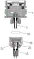
根据图7-13所示,所述第二外壳29远离第一外壳4的一端固定在灯座35上,所述灯座35通过固定杆37固定在底座36上,所述灯座35内壁盘旋嵌设有降温管道38,所述降温管道38的两端从所述灯座35靠近所述固定杆37的一端延伸至所述底座36上;所述底座36内设有储水腔66,所述储水腔66的上表面设有进水口68和出水口67,所述进水口68连接有进水管70,所述出水口67连接出水管69,所述进水管70和所述出水管69分别连接所述降温管道38的两个开口端;所述灯座35靠近所述第二外壳29的一端设有通风板39,所述通风板39远离所述第二外壳29的一端设置有风机和水压调节装置,所述风机靠近所述通风板39设置,所述水压调节装置一端连接驱动装置,另一端连接所述降温管道38靠近出水管69的一端;所述储水腔66的周向外壁还设置有注水口71。As shown in FIGS. 7-13 , the end of the
所述第一外壳4能够实现与多种规格的灯座35进行安装的目的;所述灯座35可以是通过吊环吊装在房顶或悬梁的吊灯结构,也可以是通过螺钉8直接安装在房顶或悬梁的吸顶结构;或者是通过所述固定杆37和底座36固定的泛光灯或水底灯;当作为泛光灯或者水底灯时,所述底座36通过固定杆37将灯座35进行固定,从而实现对灯模组进行安装固定的目的。所述灯座35内设置的降温管道38是盘旋设置在灯座35的内壁的,因此是能够实现对灯座35内的温度进行降温,由于所述灯模组是安装在灯座35和面罩34之间,因此,通过灯座35和面罩34均能够实现对灯模组进行导热散热的目的;所以,所述降温管道38能够经底座36中设置的储水腔66进行水冷循环;另外,所述灯座35内还设置有风机,所述风机通过对所述通风板39进行吹风,所述通风板39设为圆板结构,圆板结构表面设有多个间隔的通风孔,通风孔利于风机的风吹向同心母端子7远离同心公端子3的一端,并由此实现对同心母端子7和灯座35内进行风冷目的。The
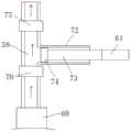
根据图8-13所示,所述风机包括:叶片47、第三转轴48和电机49,所述第三转轴48的一端周向外壁设有多个叶片47,所述第三转轴48的另一端连接第一转轴42,所述第三转轴48靠近第一转轴42的一端周向外壁设有第一齿轮40,所述第一齿轮40和第二齿轮41啮合设置,所述第二齿轮41的中心连接有第四转轴50,所述第四转轴50和第三转轴48为垂直设置,所述第四转轴50远离第二齿轮41的一端连接电机49的转动端,所述电机49远离第四转轴50的一端固定在灯座35的内壁上;所述第一齿轮40和第二齿轮41设置为相互啮合的锥齿轮;所述灯座35的内壁上设置有圆形结构的固定盘44,所述固定盘44的中心设有轴承51,所述轴承51用于连接所述第一转轴42的周向外壁;所述灯座35设置为L型结构,所述L型结构的一端用于安装灯模组,另一端用于安装在底座36上;所述第一转轴42的周向外壁设有第一连杆45,所述连杆设在所述第一转轴42远离第三转轴48的一端,所述第一连杆45远离第一转轴42的一端设有第四凸起柱43,所述第四凸起柱43设置在所述第一连杆45远离固定盘44的一面;所述第四凸起柱43上转动连接有第三轴套46,所述第三轴套46连接第三连杆63,所述第三连杆63远离第三轴套46的一端设置有第四轴套56,所述第四轴套56转动连接在第三凸起柱64上,所述第三凸起柱64的一端设在第二连板55的其中一面,所述第二连板55的另一面固定在第一连板54上,所述第一连板54远离第二连板55的一面设有滑竿53,所述滑竿53滑动设在滑道52上,所述滑道52设在所述灯座35的内壁上;所述第二连板55的一端连接第四连板57,所述第四连板57和所述第三凸起柱64设在所述第二连板55的同一表面上,所述第四连板57远离所述第二连板55的一端固定在第一轴套58上,所述第一轴套58固定设在第五转轴59上,所述第五转轴59的两端转动设在灯座35的内壁上;所述第五转轴59上还固定设置有第二轴套65,所述第二轴套65的周向外壁设置有第五连板60,所述第五连板60远离第二轴套65的一端连接第二连杆61,所述第二连杆61远离第二轴套65的一端固定连接柱塞杆73,所述柱塞杆73远离第二连杆61的一端设有活动塞74,所述活动塞74活动设在活塞管72内,所述活塞管72的的另一端连通设在所述降温管道38靠近出水管69的一端;所述降温管道38上设置有第一单向阀75和第二单向阀76,所述第一单向阀75和第二单向阀76分别设在所述活塞管72的两侧;所述第五连板60和所述第四连板57沿着所述第五转轴59的轴向中心线分别设在所述第五转轴59的两侧,且所述第一轴套58和第二轴套65间隔设在第五转轴59的周向外壁;所述滑道52和所述电机49均设在所述灯座35的同一侧内壁上;所述活塞管72靠近所述第二连杆61的一端设有密封装置,所述密封装置优选为密封胶圈,所述密封装置的外壁固定在所述活塞管72的开口内壁上,所述密封装置中心设有用于所述活动塞74来回活动的贯穿孔。As shown in FIGS. 8-13 , the fan includes:
所述滑竿53、所述第四连板57和第五连板60均为平行设置,且所述第四连板57和第五连板60的平面均与所述固定盘44的表面平行设置;所述第三连杆63位于所述固定盘44和所述第四连板57之间,并且所述第三连杆63相对于第四连板57和固定盘44的平面为倾斜设置。The sliding
所述注水口71用于对所述储水腔66内进行加水或放水,所述注水口71的开口端设有密封堵,当需要注水或放水时,通过拔掉密封堵就能实现对所述储水腔66进行加水或放水的目的。The
通过利用所述风机能够对所述灯座35内部进行风冷,而通过所述水压调节装置能够使得所述储水腔66内的水进行吸附至所述降温管道38内,提高降温管道38的水流速度,实现降温管道38能够加速降温的目的,进一步使得降温管道38内的水将所述灯座35、第一外壳4和第二外壳29的热量进行降温;由此提高所述灯模组的使用寿命。具体工作时,首先所述风机启动工作,风机启动工作后,所述水压调节装置就会被联动着工作,所述水压调节装置工作后,风机和水压调节装置就能共同实现风冷和水冷的目的,由此实现对灯模组进行降温的目的。By using the fan, the inside of the
其工作原理为:所述电机49经导线9连接电源,当电源启动后,将所述电机49和所述灯模组分别进行启动;所述电机49启动后,所述第四转轴50就会转动,所述第四转轴50转动后带动第一齿轮40转动,所述第一齿轮40转动后啮合第二齿轮41转动,所述第二齿轮41转动后带动第三转轴48和第一转轴42转动,所述第三转轴48转动后就会带动叶片47转动,所述叶片47转动就能实现吹风,所述叶片47的风经通风板39吹向第二外壳29方向,从而对第二外壳29进行风冷的目的;The working principle is as follows: the
所述第一转轴42转动后,就会带动第一连杆45转动,所述第一连杆45转动后就会使得第一连杆45上的第四凸起柱43绕着第一转轴42的轴向中心线进行圆周运动,由此带着经第三轴套46上固定设置的第三连杆63进行转动,所述第三连杆63也会随之进行圆周运动;After the first
所述第三连杆63远离第一连杆45的一端转动设在第三凸起柱64上,所述第三凸起柱64、第一连板54和第二连板55均为固定连接;所述第四连板57的另一端通过第一轴套58固定在第五转轴59的周向外壁;而所述第五转轴59的两端则转动设在灯座35的内壁上;因此,所述第三连杆63会就会使得第一连板54和第二连板55进行摆动,所述第一连板54所连接的滑竿53就会在滑道52上来回活动,也会带着所述第五转轴59来回转动,所述第五转轴59来回转动后,就会带动所述第二轴套65和第五连板60也来回摆动,所述第五连板60摆动后就会带动所述第二连杆61在图8中左右活动,图9中的第二连杆61表示为上下活动方向;The end of the third connecting
所述第二连杆61远离第五连板60的一端是固定连接柱塞杆73的,所述柱塞杆73也会带着来回活动,由此使得所述活动塞74能够在活塞管72内来回活动,当所述活动塞74在活塞管72内来回活动时,就会使得活塞管72内的气压进行变化;在图12中,当柱塞杆73往右移动时,第二单向阀76单向阀打开,第一单向阀75单向阀关闭,储水腔66的水经出水口67和出水管69引入第一单向阀75和第二单向阀76之间的降温管道38内,填充满位于第一单向阀75和第二单向阀76之间的降温管道38;当柱塞杆73往左移动时,第二单向阀76关闭,第一单向阀75打开,位于第一单向阀75和第二单向阀76之间的降温管道38内水被加压并经自第一单向阀75流向降温管道38的另一端;如此反复就能够间歇的将储水腔66的水经降温管道38的一端引流至降温管道38内,再经降温管道38的另一端反流回所述储水腔66内,实现对降温管道38内的水进行循环的目的,就能加速降温效率,使得灯模组实现加速降温的目的。The end of the second connecting
显然,本领域的技术人员可以对本发明进行各种改动和变型而不脱离本发明的精神和范围。这样,倘若本发明的这些修改和变型属于本发明权利要求及其等同技术的范围之内,则本发明也意图包含这些改动和变型在内。It will be apparent to those skilled in the art that various modifications and variations can be made in the present invention without departing from the spirit and scope of the invention. Thus, provided that these modifications and variations of the present invention fall within the scope of the claims of the present invention and their equivalents, the present invention is also intended to include these modifications and variations.
Claims (8)
Translated fromChinesePriority Applications (13)
| Application Number | Priority Date | Filing Date | Title |
|---|---|---|---|
| CN201911420142.2ACN110985903B (en) | 2019-12-31 | 2019-12-31 | Lamp module |
| PCT/CN2020/070502WO2021134806A1 (en) | 2019-12-31 | 2020-01-06 | Lamp module |
| US16/645,458US11162651B2 (en) | 2019-12-31 | 2020-01-06 | Lamp module group |
| US17/389,019US11598517B2 (en) | 2019-12-31 | 2021-07-29 | Electronic module group |
| US17/463,086US11466821B2 (en) | 2019-12-31 | 2021-08-31 | Lamp module group |
| US17/895,557US11959601B2 (en) | 2019-12-31 | 2022-08-25 | Lamp module group |
| US18/100,300US12018828B2 (en) | 2019-12-31 | 2023-01-23 | Electronic module group |
| US18/201,631US12281783B2 (en) | 2019-12-31 | 2023-05-24 | Electronic module group |
| US18/243,329US12270535B2 (en) | 2019-12-31 | 2023-09-07 | Electronic module group |
| US18/593,654US12435846B2 (en) | 2019-12-31 | 2024-03-01 | Lamp module group |
| US18/958,510US20250084988A1 (en) | 2019-12-31 | 2024-11-25 | Electronic module group |
| US19/042,415US20250180200A1 (en) | 2019-12-31 | 2025-01-31 | Electronic module group |
| US19/063,888US20250198609A1 (en) | 2019-12-31 | 2025-02-26 | Electronic module group |
Applications Claiming Priority (1)
| Application Number | Priority Date | Filing Date | Title |
|---|---|---|---|
| CN201911420142.2ACN110985903B (en) | 2019-12-31 | 2019-12-31 | Lamp module |
Publications (2)
| Publication Number | Publication Date |
|---|---|
| CN110985903A CN110985903A (en) | 2020-04-10 |
| CN110985903Btrue CN110985903B (en) | 2020-08-14 |
Family
ID=70080208
Family Applications (1)
| Application Number | Title | Priority Date | Filing Date |
|---|---|---|---|
| CN201911420142.2AActiveCN110985903B (en) | 2019-12-31 | 2019-12-31 | Lamp module |
Country Status (3)
| Country | Link |
|---|---|
| US (4) | US11162651B2 (en) |
| CN (1) | CN110985903B (en) |
| WO (1) | WO2021134806A1 (en) |
Families Citing this family (11)
| Publication number | Priority date | Publication date | Assignee | Title |
|---|---|---|---|---|
| US10197252B2 (en)* | 2016-01-29 | 2019-02-05 | Hunter Industries, Inc. | Light fixture with removable light cartridge |
| US12281783B2 (en) | 2019-12-31 | 2025-04-22 | Lumien Enterprise, Inc. | Electronic module group |
| US11598517B2 (en) | 2019-12-31 | 2023-03-07 | Lumien Enterprise, Inc. | Electronic module group |
| CN110985903B (en) | 2019-12-31 | 2020-08-14 | 江苏舒适照明有限公司 | Lamp module |
| CN111503556B (en) | 2020-04-23 | 2020-11-27 | 江苏舒适照明有限公司 | a spotlight structure |
| KR102369442B1 (en)* | 2020-09-02 | 2022-03-03 | 삼성전기주식회사 | Camera Module |
| CN214580724U (en)* | 2021-02-23 | 2021-11-02 | 苏州欧普照明有限公司 | Down lamp |
| US12230950B2 (en) | 2021-07-29 | 2025-02-18 | Lumien Enterprise, Inc. | Junction box |
| CN115376854B (en)* | 2022-08-24 | 2025-09-19 | 东莞福哥电子有限公司 | Modularized 3D rocker convenient for replacing LED module |
| US12331907B2 (en) | 2023-07-10 | 2025-06-17 | Hunter Industries, Inc. | Light fixture with expanding collar |
| CN117308058B (en)* | 2023-10-10 | 2024-03-29 | 东莞莱姆森科技建材有限公司 | UVC lamp pearl module and have mirror cabinet of this UVC lamp pearl module |
Citations (4)
| Publication number | Priority date | Publication date | Assignee | Title |
|---|---|---|---|---|
| CN101832493A (en)* | 2009-03-05 | 2010-09-15 | 株式会社中西 | Luminescent device |
| KR101420351B1 (en)* | 2014-05-08 | 2014-07-17 | (주)루빛 | The electric shoch preventing equipment for a lighting apparatus |
| CN105889771A (en)* | 2016-04-29 | 2016-08-24 | 林家鹳 | Replaceable LED lamp |
| CN109140397A (en)* | 2014-11-28 | 2019-01-04 | 欧普照明股份有限公司 | A kind of lamps and lanterns fixing seat and light fitting connecting seat and a kind of lamp fixing device |
Family Cites Families (360)
| Publication number | Priority date | Publication date | Assignee | Title |
|---|---|---|---|---|
| US1180658A (en)* | 1913-10-23 | 1916-04-25 | Firm Robert Bosch | Electric-lamp fixture. |
| US2163673A (en) | 1937-03-12 | 1939-06-27 | Stewart R Browne Mfg Co Inc | Lighting device |
| US2668901A (en) | 1949-12-15 | 1954-02-09 | Jr Merritt B Austin | Lamp holder for reflector-type outdoor lamps |
| US2738756A (en) | 1954-11-01 | 1956-03-20 | Gen Motors Corp | Illuminated dial devices |
| US3104064A (en) | 1961-03-22 | 1963-09-17 | Bell Electric Co | Stake-down outdoor light |
| DE10006410A1 (en) | 2000-02-14 | 2001-08-16 | Zumtobel Staff Gmbh | lamp |
| JPS5124978B2 (en) | 1971-12-07 | 1976-07-28 | ||
| JPS5222866Y2 (en) | 1972-02-15 | 1977-05-25 | ||
| US3792753A (en) | 1972-02-18 | 1974-02-19 | J Smith | Acoustical device |
| JPS5124978U (en) | 1974-08-14 | 1976-02-24 | ||
| GB1585270A (en) | 1976-07-16 | 1981-02-25 | Exxon Research Engineering Co | Method and apparatus for investigating the mobility of a substance |
| JPS5354209U (en) | 1976-10-12 | 1978-05-10 | ||
| CH607571A5 (en) | 1977-02-01 | 1978-08-31 | Orbisphere Corp | |
| US4186851A (en) | 1977-02-24 | 1980-02-05 | Personal Security Concepts, Inc. | Non-lethal personal defense weapon |
| US4495463A (en) | 1982-02-24 | 1985-01-22 | General Electric Company | Electronic watt and/or watthour measuring circuit having active load terminated current sensor for sensing current and providing automatic zero-offset of current sensor DC offset error potentials |
| US4596449A (en) | 1982-12-14 | 1986-06-24 | West Electric Company Ltd. | Zoom lens apparatus |
| US4530039A (en) | 1983-09-29 | 1985-07-16 | Shin Shi Steve S | Multi-section multi-purpose hand light |
| US5260858A (en) | 1984-09-06 | 1993-11-09 | Mag Instrument, Inc. | Flashlight |
| JPS6182417U (en) | 1984-11-07 | 1986-05-31 | ||
| US4739457A (en) | 1986-08-11 | 1988-04-19 | Orr Allie E | Illuminating device support |
| US4831664A (en) | 1987-05-14 | 1989-05-23 | Redi-Corp Protective Materials, Inc. | Garment for protecting against environmental contamination |
| US4853722A (en) | 1987-08-14 | 1989-08-01 | Sea Fathoms Industries | Method and apparatus for extending the depth range of underwater equipment |
| US4963798A (en) | 1989-02-21 | 1990-10-16 | Mcdermott Kevin | Synthesized lighting device |
| US4996635A (en)* | 1989-10-13 | 1991-02-26 | Deepsea Power & Light, Inc. | Deep submersible light assembly with dry pressure dome |
| US5161883A (en) | 1989-10-19 | 1992-11-10 | Musco Corporation | Means and method for increasing output, efficiency, and flexibility of use of an arc lamp |
| IT1247165B (en) | 1991-03-15 | 1994-12-12 | Fidia Spa | THERAPEUTIC USE OF PHOSPHATIDYLSERINE AND DERIVATIVES IN DEGENERATIVE PATHOLOGIES, ALSO ASSOCIATED WITH IMMUNITARY DYSFUNCTIONS. |
| US6135611A (en) | 1991-06-21 | 2000-10-24 | Mag Instrument, Inc. | Miniature flashlight |
| US5249109A (en) | 1991-08-09 | 1993-09-28 | Intermatic Incorporated | Outdoor variable focus light fixture |
| FR2683296B1 (en) | 1991-11-06 | 1994-01-28 | Angenieux Ets Pierre | VARIABLE ILLUMINATED FIELD LIGHTING SYSTEM. |
| US5319959A (en) | 1992-10-16 | 1994-06-14 | The United States Of America As Represented By The Secretary Of The Army | Air lubricated penetrometer rod system |
| JPH06182417A (en) | 1992-12-17 | 1994-07-05 | Nippon Steel Corp | Controller for meandering of rolled stock |
| US5513085A (en) | 1993-01-28 | 1996-04-30 | Bourne; Steven M. | Retractable light and motion detector |
| US5331523A (en) | 1993-07-09 | 1994-07-19 | Delzer David G | Gas dispensing flashlight apparatus |
| US5373427A (en) | 1993-09-10 | 1994-12-13 | Mclean; Roderick G. | Dispenser with source of illumination for self-defense spray canister |
| US5454611A (en) | 1994-02-04 | 1995-10-03 | The Big Strapper Corporation | Strap installer |
| US5420766A (en) | 1994-03-07 | 1995-05-30 | Hollis; Bob J. | Defensive light device |
| US6633110B2 (en) | 1994-03-22 | 2003-10-14 | Tailored Lighting Inc. | Underwater lamp |
| DE4445987C1 (en) | 1994-12-22 | 1996-03-07 | Adolf Tuscher | Hand=operated defence and anti=aggression appts. |
| US5690424A (en) | 1995-05-08 | 1997-11-25 | Justice Design Group, Inc. | Mounting apparatus for lighting fixtures |
| US5825308A (en) | 1996-11-26 | 1998-10-20 | Immersion Human Interface Corporation | Force feedback interface having isotonic and isometric functionality |
| US5570949A (en)* | 1995-12-29 | 1996-11-05 | Chiang; Hanh | Torch with a bellowed intermediate flexible hose member |
| US5571278A (en) | 1995-12-29 | 1996-11-05 | Chiang; Hanh | Torch with a bellowed intermediate flexible hose member |
| US5736965A (en) | 1996-02-07 | 1998-04-07 | Lutron Electronics Co. Inc. | Compact radio frequency transmitting and receiving antenna and control device employing same |
| US5826971A (en) | 1996-04-10 | 1998-10-27 | Nordic Lights, Inc. | Slide focus flashlight |
| DE19620209A1 (en) | 1996-05-20 | 1997-11-27 | Zumtobel Licht | Luminaire with a profiled base body as a support for at least one lamp |
| TW330233B (en) | 1997-01-23 | 1998-04-21 | Philips Eloctronics N V | Luminary |
| CN1192682C (en) | 1997-08-01 | 2005-03-09 | 皇家菲利浦电子有限公司 | Circuit arrangement, and signaling light provided with circuit arrangement |
| US5904417A (en) | 1997-08-04 | 1999-05-18 | Buhl Electric, Inc. | Light fixture with elliptical reflector and mechanical shutter dimmer |
| US6806659B1 (en) | 1997-08-26 | 2004-10-19 | Color Kinetics, Incorporated | Multicolored LED lighting method and apparatus |
| US6525414B2 (en) | 1997-09-16 | 2003-02-25 | Matsushita Electric Industrial Co., Ltd. | Semiconductor device including a wiring board and semiconductor elements mounted thereon |
| US6390647B1 (en) | 1997-12-31 | 2002-05-21 | Louisa Shaefer | Night light |
| US6113252A (en) | 1998-02-17 | 2000-09-05 | Vari-Lite, Inc. | Architectural luminaries |
| JP3875392B2 (en) | 1998-02-23 | 2007-01-31 | 株式会社東芝 | Operational amplifier |
| US6161948A (en) | 1998-05-27 | 2000-12-19 | B-K Lighting, Inc. | Adjustable mount for sealed light systems |
| US6092914A (en) | 1998-06-22 | 2000-07-25 | Electronics Theatre Controls | Zoom lighting fixture having multifunction actuator |
| DE69912391T2 (en) | 1998-07-01 | 2004-08-19 | Koninklijke Philips Electronics N.V. | CIRCUIT ARRANGEMENT AND SIGNAL LIGHT THEREFORE |
| USD424731S (en) | 1998-07-14 | 2000-05-09 | Kim Lighting Inc. | Landscape luminaire |
| US6290368B1 (en) | 1999-05-21 | 2001-09-18 | Robert A. Lehrer | Portable reading light device |
| IT1318520B1 (en) | 2000-05-16 | 2003-08-27 | Henkel Spa | PERFUME CONTAINER WITH SOUND OR LIGHT GENERATOR. |
| US7038399B2 (en) | 2001-03-13 | 2006-05-02 | Color Kinetics Incorporated | Methods and apparatus for providing power to lighting devices |
| JP3673943B2 (en) | 2001-03-28 | 2005-07-20 | 独立行政法人理化学研究所 | Short-focus lens condensing type light-emitting diode illuminator |
| DE60137972D1 (en) | 2001-04-12 | 2009-04-23 | Matsushita Electric Works Ltd | LIGHT SOURCE ELEMENT WITH LED AND METHOD FOR THE PRODUCTION THEREOF |
| CZ20011822A3 (en) | 2001-05-23 | 2002-09-11 | Břetislav Ing. Košťál | Compound device for personal defense |
| US7192303B2 (en) | 2001-05-31 | 2007-03-20 | Ran Kohen | Quick connect device for electrical fixtures |
| US6612720B1 (en) | 2001-07-19 | 2003-09-02 | Joshua Z. Beadle | Spot light fixture with beam adjustment |
| US6652113B2 (en) | 2001-10-01 | 2003-11-25 | Robert J. Tant | Dual mode indirect fluorescent lighting fixture |
| US6586890B2 (en) | 2001-12-05 | 2003-07-01 | Koninklijke Philips Electronics N.V. | LED driver circuit with PWM output |
| US6679315B2 (en) | 2002-01-14 | 2004-01-20 | Marconi Communications, Inc. | Small scale chip cooler assembly |
| US6641283B1 (en) | 2002-04-12 | 2003-11-04 | Gelcore, Llc | LED puck light with detachable base |
| US7358679B2 (en) | 2002-05-09 | 2008-04-15 | Philips Solid-State Lighting Solutions, Inc. | Dimmable LED-based MR16 lighting apparatus and methods |
| AU2003243664A1 (en) | 2002-06-20 | 2004-01-06 | Eveready Battery Company, Inc. | Lighting device with adjustable spotlight beam |
| US6748096B2 (en) | 2002-07-03 | 2004-06-08 | Pao-An Chuang | Bulb type speaker structure |
| GB0216448D0 (en) | 2002-07-16 | 2002-08-21 | Mcleish Graham | Connector |
| US7204608B2 (en) | 2002-07-23 | 2007-04-17 | Beeman Holdings Inc. | Variable color landscape lighting |
| JP3599727B2 (en) | 2002-09-09 | 2004-12-08 | 丸茂電機株式会社 | Spotlight |
| US6764197B1 (en) | 2002-09-13 | 2004-07-20 | Raymond A. Zemar | Spotlight for use in illuminating ornamental displays |
| US6883941B2 (en) | 2002-09-23 | 2005-04-26 | Steven B. Cutting | Landscape light fixture |
| US7084353B1 (en) | 2002-12-11 | 2006-08-01 | Emc Corporation | Techniques for mounting a circuit board component to a circuit board |
| FI2964000T3 (en) | 2002-12-19 | 2023-01-13 | Led driver | |
| US20050174782A1 (en) | 2003-03-25 | 2005-08-11 | Chapman Leonard T. | Flashlight |
| US7015825B2 (en) | 2003-04-14 | 2006-03-21 | Carpenter Decorating Co., Inc. | Decorative lighting system and decorative illumination device |
| CA2634475C (en) | 2003-07-07 | 2014-05-20 | Brasscorp Limited | Led-based inspection lamp with improved collimation optics |
| US7160001B2 (en) | 2003-10-14 | 2007-01-09 | Cooper Industries | Focus assembly for a track light |
| US6940012B2 (en) | 2003-10-28 | 2005-09-06 | B-K Lighting, Inc. | Method and apparatus for providing an environmental barrier between an interior and exterior of an electrical enclosure using a plug and seal |
| US7109668B2 (en) | 2003-10-30 | 2006-09-19 | I.E.P.C. Corp. | Electronic lighting ballast |
| US7163313B2 (en) | 2003-11-04 | 2007-01-16 | Maury Rosenberg | Illumination device |
| US7063553B1 (en)* | 2003-11-10 | 2006-06-20 | Nate Mullen | Quick release socket |
| US8096674B2 (en) | 2003-12-09 | 2012-01-17 | Surefire, Llc | Lighting device with selectable output level switching |
| AU2003271383A1 (en) | 2003-12-23 | 2005-07-07 | Hpm Industries Pty Ltd | A Solar Powered Light Assembly to Produce Light of Varying Colours |
| US7178937B2 (en) | 2004-01-23 | 2007-02-20 | Mcdermott Vernon | Lighting device and method for lighting |
| WO2011143510A1 (en) | 2010-05-12 | 2011-11-17 | Lynk Labs, Inc. | Led lighting system |
| EP3589081B1 (en) | 2004-03-15 | 2024-02-21 | Signify North America Corporation | Power control methods and apparatus |
| GB2413840B (en) | 2004-05-07 | 2006-06-14 | Savage Marine Ltd | Underwater lighting |
| JP4590283B2 (en) | 2004-05-21 | 2010-12-01 | シャープ株式会社 | Backlight unit and liquid crystal display device including the same |
| US7847486B2 (en) | 2004-08-04 | 2010-12-07 | Dr. LED (Holdings), Inc | LED lighting system |
| US8733966B2 (en) | 2004-08-20 | 2014-05-27 | Mag Instrument, Inc. | LED flashlight |
| WO2006042051A2 (en) | 2004-10-08 | 2006-04-20 | B/E Aerospace, Inc. | Lighting apparatus |
| GB2418979B (en) | 2004-10-11 | 2007-07-11 | Spearmark Internat Ltd | A mechanical dimmer for a luminaire |
| KR100953596B1 (en) | 2004-11-10 | 2010-04-21 | 캐논 가부시끼가이샤 | Light emitting device |
| US7326179B1 (en) | 2004-12-02 | 2008-02-05 | Juan Enrique Cienfuegos | Illuminated display system and method of use |
| US7452099B2 (en) | 2005-01-21 | 2008-11-18 | Cyberlux Corporation | Portable light device |
| US20060187653A1 (en)* | 2005-02-10 | 2006-08-24 | Olsson Mark S | LED illumination devices |
| ES2331750T3 (en)* | 2005-03-08 | 2010-01-14 | Grant Harold Amor | LED LIGHTING DEVICE (LIGHT EMITTER DIODE) IN A PLASTIC HOUSING. |
| US7736025B2 (en) | 2005-04-18 | 2010-06-15 | Koninklijke Philips Electronics N.V. | Illumination system comprising mechanical dimming device |
| US20070019415A1 (en) | 2005-04-22 | 2007-01-25 | Itt Industries | LED floodlight system |
| US20060262542A1 (en) | 2005-05-18 | 2006-11-23 | Jji Lighting Group, Inc. | Modular landscape light fixture |
| US7896524B2 (en) | 2005-06-01 | 2011-03-01 | Ccs, Inc. | Light irradiation apparatus |
| JP2006344602A (en) | 2005-06-09 | 2006-12-21 | Samsung Electronics Co Ltd | Lamp, lamp holder, power supply module, backlight assembly having the same, and display device |
| JP5124978B2 (en) | 2005-06-13 | 2013-01-23 | 日亜化学工業株式会社 | Light emitting device |
| US7249871B2 (en) | 2005-06-14 | 2007-07-31 | Seed Lighting Design Co., Ltd. | Vertical adjuster for suspending lamp |
| TWM295720U (en) | 2005-08-09 | 2006-08-11 | Wei-Chiang Lee | LED full-color display lamp |
| TWI391600B (en) | 2005-09-27 | 2013-04-01 | Koninkl Philips Electronics Nv | Led lighting fixtures |
| US7534975B1 (en) | 2006-02-02 | 2009-05-19 | Streamlight, Inc. | Flashlight and light source selector |
| US7922353B2 (en) | 2006-03-20 | 2011-04-12 | Larson Isely | Apparatus, method and system for providing multi-mode illumination |
| DE202006006481U1 (en) | 2006-04-22 | 2006-06-22 | HÜBNER, Michael | Street-light with adjustment- and dimming-device, has reflector adjustment coupled to dimmer to effect reduction of light-beam section |
| DE202006007227U1 (en) | 2006-04-28 | 2006-07-20 | Arnold & Richter Cine Technik Gmbh & Co. Betriebs Kg | Dimming device for a headlight |
| US8235539B2 (en) | 2006-06-30 | 2012-08-07 | Electraled, Inc. | Elongated LED lighting fixture |
| US7738235B2 (en) | 2006-07-31 | 2010-06-15 | B/E Aerospace, Inc. | LED light apparatus |
| US7733659B2 (en) | 2006-08-18 | 2010-06-08 | Delphi Technologies, Inc. | Lightweight audio system for automotive applications and method |
| US7549766B2 (en) | 2006-08-23 | 2009-06-23 | Streamlight, Inc. | Light including an electro-optical “photonic” selector switch |
| CN200996560Y (en) | 2006-09-25 | 2007-12-26 | 苏辉云 | External-independent electric torch of socket |
| US20080080187A1 (en) | 2006-09-28 | 2008-04-03 | Purinton Richard S | Sealed LED light bulb |
| US7373894B2 (en)* | 2006-10-10 | 2008-05-20 | Steven Rowley | Window housing for use with thru-hull fittings |
| US7837866B2 (en) | 2006-10-12 | 2010-11-23 | Burrows Bruce D | Drainless reverse osmosis water purification system |
| DE102006051026A1 (en) | 2006-10-26 | 2008-04-30 | Erco Leuchten Gmbh | Luminaire i.e. workplace luminaire, has manual operating device for controller arranged directly on housing, with handle moved or operated along two directions in functional planes such that parameter associated with plane is changed |
| US20080123340A1 (en) | 2006-11-27 | 2008-05-29 | Mcclellan Thomas | Light device having LED illumination and electronic circuit board in an enclosure |
| US7789326B2 (en) | 2006-12-29 | 2010-09-07 | Water Pik, Inc. | Handheld showerhead with mode control and method of selecting a handheld showerhead mode |
| US8172434B1 (en) | 2007-02-23 | 2012-05-08 | DeepSea Power and Light, Inc. | Submersible multi-color LED illumination system |
| US7445365B1 (en) | 2007-07-24 | 2008-11-04 | Lezi Enterprise Co., Ltd. | Position adjustment device for headlight of car |
| JP4894688B2 (en) | 2007-09-05 | 2012-03-14 | 東芝ライテック株式会社 | Lighting device |
| US20090097401A1 (en) | 2007-10-12 | 2009-04-16 | Wael William Diab | Method and system for configurable data rate thresholds for energy efficient ethernet |
| US20090205935A1 (en) | 2008-01-31 | 2009-08-20 | Night Operations Systems | Reed and pressure switching system for use in a lighting system |
| US8575641B2 (en) | 2011-08-11 | 2013-11-05 | Goldeneye, Inc | Solid state light sources based on thermally conductive luminescent elements containing interconnects |
| US8138690B2 (en) | 2008-04-14 | 2012-03-20 | Digital Lumens Incorporated | LED-based lighting methods, apparatus, and systems employing LED light bars, occupancy sensing, local state machine, and meter circuit |
| CN102089567B (en) | 2008-07-07 | 2014-02-26 | 松下电器产业株式会社 | Light source for bulb-shaped lighting |
| US8033677B1 (en)* | 2008-08-01 | 2011-10-11 | DeepSea Power and Light, Inc. | Deep submersible light with pressure compensation |
| US20110204777A1 (en) | 2008-08-18 | 2011-08-25 | Switch Bulb Company, Inc. | Settable light bulbs |
| US8147089B2 (en)* | 2008-10-09 | 2012-04-03 | Surefire, Llc | Switchable light sources |
| US8827512B1 (en) | 2008-10-19 | 2014-09-09 | Hunter Industries Incorporated | Pathway light fixture with releasably sealed lamp enclosure |
| US10509304B2 (en) | 2008-11-12 | 2019-12-17 | Tseng-Lu Chien | LED projection light has features |
| US8049427B2 (en) | 2008-11-25 | 2011-11-01 | Lutron Electronics Co., Inc. | Load control device having a visual indication of energy savings and usage information |
| US20100226139A1 (en) | 2008-12-05 | 2010-09-09 | Permlight Products, Inc. | Led-based light engine |
| US8651704B1 (en) | 2008-12-05 | 2014-02-18 | Musco Corporation | Solid state light fixture with cooling system with heat rejection management |
| US8070328B1 (en) | 2009-01-13 | 2011-12-06 | Koninkliljke Philips Electronics N.V. | LED downlight |
| US8169165B2 (en) | 2009-01-14 | 2012-05-01 | Mag Instrument, Inc. | Multi-mode portable lighting device |
| US8220970B1 (en) | 2009-02-11 | 2012-07-17 | Koninklijke Philips Electronics N.V. | Heat dissipation assembly for an LED downlight |
| US8066396B2 (en) | 2009-02-24 | 2011-11-29 | Surefire, Llc | Headlamp lighting device |
| US8598793B2 (en) | 2011-05-12 | 2013-12-03 | Ledengin, Inc. | Tuning of emitter with multiple LEDs to a single color bin |
| US20100259200A1 (en) | 2009-04-14 | 2010-10-14 | Beausoleil David M | Led lighting device |
| US8148912B2 (en) | 2009-05-01 | 2012-04-03 | Surefire, Llc | Lighting device with staggered light sources responsive to a single user control |
| US8162502B1 (en) | 2009-05-27 | 2012-04-24 | Zlatko Zadro | Illuminated continuously rotatable dual magnification mirror |
| CN201428965Y (en) | 2009-06-18 | 2010-03-24 | 熊胜群 | High-power LED light source module |
| US8186852B2 (en) | 2009-06-24 | 2012-05-29 | Elumigen Llc | Opto-thermal solution for multi-utility solid state lighting device using conic section geometries |
| CN201496788U (en) | 2009-07-01 | 2010-06-02 | 戴忠果 | LED underwater lamp |
| CA2768777C (en) | 2009-07-21 | 2017-11-28 | Cooper Technologies Company | Interfacing a light emitting diode (led) module to a heat sink assembly, a light reflector and electrical circuits |
| US10352550B1 (en)* | 2009-07-29 | 2019-07-16 | Deepsea Power & Light Llc | Submersible LED light fixture with multilayer stack for pressure transfer |
| KR101677730B1 (en) | 2009-08-14 | 2016-11-30 | 페어차일드코리아반도체 주식회사 | LED light emitting device |
| US8093511B2 (en) | 2009-08-26 | 2012-01-10 | Creality Ab | Ceiling suspension assembly |
| US9285103B2 (en) | 2009-09-25 | 2016-03-15 | Cree, Inc. | Light engines for lighting devices |
| US20110075404A1 (en) | 2009-09-28 | 2011-03-31 | Linda Allen | Battery powered indoor/outdoor decorative table and floor lamp and led based light bulb |
| US20110080741A1 (en) | 2009-10-06 | 2011-04-07 | Si Chung Noh | Lighting fixture |
| CN201651985U (en) | 2009-10-23 | 2010-11-24 | 叶信平 | Illuminating lamp for sewing machine |
| US8662709B2 (en) | 2009-11-23 | 2014-03-04 | General Scientific Corporation | LED illuminator with improved beam quality |
| US8664881B2 (en) | 2009-11-25 | 2014-03-04 | Lutron Electronics Co., Inc. | Two-wire dimmer switch for low-power loads |
| CN102668712A (en) | 2009-11-25 | 2012-09-12 | 株式会社村田制作所 | LED driving power supply unit and LED lighting unit |
| JP5354209B2 (en) | 2010-01-14 | 2013-11-27 | 東芝ライテック株式会社 | Light bulb shaped lamp and lighting equipment |
| CN201661934U (en) | 2010-01-29 | 2010-12-01 | 大连电子工业股份有限公司 | Lamp structure capable of focusing |
| JP2011165394A (en) | 2010-02-05 | 2011-08-25 | Sharp Corp | Led drive circuit, dimming device, led illumination fixture, led illumination device, and led illumination system |
| WO2011100972A1 (en) | 2010-02-16 | 2011-08-25 | Martin Professional A/S | Illumination device with interlocked yoke shell parts |
| US9062830B2 (en) | 2010-03-03 | 2015-06-23 | Cree, Inc. | High efficiency solid state lamp and bulb |
| US10359151B2 (en) | 2010-03-03 | 2019-07-23 | Ideal Industries Lighting Llc | Solid state lamp with thermal spreading elements and light directing optics |
| US8931933B2 (en) | 2010-03-03 | 2015-01-13 | Cree, Inc. | LED lamp with active cooling element |
| US8882284B2 (en) | 2010-03-03 | 2014-11-11 | Cree, Inc. | LED lamp or bulb with remote phosphor and diffuser configuration with enhanced scattering properties |
| US9500325B2 (en) | 2010-03-03 | 2016-11-22 | Cree, Inc. | LED lamp incorporating remote phosphor with heat dissipation features |
| US8632196B2 (en) | 2010-03-03 | 2014-01-21 | Cree, Inc. | LED lamp incorporating remote phosphor and diffuser with heat dissipation features |
| CN201697032U (en) | 2010-03-04 | 2011-01-05 | 赵建和 | LED lamp head capable of regulating light and color |
| CN102783253B (en) | 2010-04-09 | 2014-08-20 | 三菱化学株式会社 | Dimming device and LED lighting system |
| CA2796449A1 (en) | 2010-04-16 | 2011-10-20 | Sunovia Energy Technologies, Inc. | Solid state outdoor overhead lamp assembly |
| DK177579B1 (en) | 2010-04-23 | 2013-10-28 | Martin Professional As | Led light fixture with background lighting |
| US8950895B2 (en) | 2010-04-23 | 2015-02-10 | Martin Professional Aps | Moving head light fixture with protruding diffuser cover and multiple light sources |
| JP5595144B2 (en) | 2010-07-01 | 2014-09-24 | 三菱電機株式会社 | lighting equipment |
| US8796531B2 (en) | 2010-07-15 | 2014-08-05 | Ambrosonics, Llc | Programmable pickup director switching system and method of use |
| TWI462351B (en) | 2010-07-19 | 2014-11-21 | Interlight Optotech Corp | Led light module and manufacturing method thereof |
| CN201795292U (en) | 2010-07-23 | 2011-04-13 | 天津三协科技有限公司 | LED torch |
| CN103097805B (en) | 2010-09-10 | 2016-05-04 | 皇家飞利浦电子股份有限公司 | For the device of spotlighting |
| WO2012037574A2 (en) | 2010-09-17 | 2012-03-22 | DeepSea Power and Light, Inc. | Led spherical light fixtures with enhanced heat dissipation |
| US8403530B2 (en) | 2010-09-21 | 2013-03-26 | Honeywell International Inc. | LED spotlight including elliptical and parabolic reflectors |
| TWI449866B (en) | 2010-09-30 | 2014-08-21 | Hon Hai Prec Ind Co Ltd | Led illuminating device |
| US20120139426A1 (en) | 2010-12-03 | 2012-06-07 | General Electric Company | Dimmable outdoor luminaires |
| US8038481B1 (en) | 2011-05-05 | 2011-10-18 | General Electric Company | Receptacle connector between controller and lighting fixture |
| US20120091900A1 (en) | 2010-10-15 | 2012-04-19 | Bernard Fournier | Outdoor lighting system |
| CN201868044U (en) | 2010-10-27 | 2011-06-15 | 深圳市洲明科技股份有限公司 | Outdoor LED (Light-Emitting Diode) display module |
| US9863622B1 (en) | 2010-11-17 | 2018-01-09 | Light & Motion Industries | Underwater lights for divers |
| US9746170B1 (en) | 2010-11-17 | 2017-08-29 | Light & Motion Industries | Adjustable light for underwater photography |
| US9188292B2 (en) | 2010-11-17 | 2015-11-17 | Light & Motion Industries | Diver's underwater light for selecting between two types of light |
| KR101676019B1 (en) | 2010-12-03 | 2016-11-30 | 삼성전자주식회사 | Light source for illuminating device and method form manufacturing the same |
| US9453624B2 (en) | 2011-01-13 | 2016-09-27 | Streamlight, Inc. | Portable light with light source module and light source module |
| CN202001978U (en) | 2011-01-14 | 2011-10-05 | 浙江晶日照明科技有限公司 | Touch light-dimming type LED (light-emitting diode) courtyard lamp |
| CN103298887A (en) | 2011-01-26 | 2013-09-11 | 道康宁公司 | High temperature stable thermally conductive materials |
| US9234655B2 (en) | 2011-02-07 | 2016-01-12 | Cree, Inc. | Lamp with remote LED light source and heat dissipating elements |
| US20120243213A1 (en) | 2011-03-25 | 2012-09-27 | Chi Gon Chen | Outdoor led light fixture with dimmer switch |
| US20130088152A1 (en) | 2011-03-31 | 2013-04-11 | B-K Lighting, Inc. | Dimming apparatus for solid state lighting fixtures |
| CN202065923U (en) | 2011-04-13 | 2011-12-07 | 正屋(厦门)电子有限公司 | Beam regulation structure of light-emitting diode (LED) lamp |
| CN202132720U (en) | 2011-07-15 | 2012-02-01 | 王佳宁 | Flashlight with universal serial bus (USB) port |
| US8905587B1 (en) | 2011-08-09 | 2014-12-09 | The Boeing Company | Internal covert IR filter for searchlight systems |
| US8704262B2 (en) | 2011-08-11 | 2014-04-22 | Goldeneye, Inc. | Solid state light sources with common luminescent and heat dissipating surfaces |
| US8979353B2 (en) | 2011-08-11 | 2015-03-17 | Starlights, Inc. | Light fixture having modular accessories and method of forming same |
| WO2013021940A1 (en) | 2011-08-11 | 2013-02-14 | シャープ株式会社 | Lighting device, display device, and television receiving device |
| EP2743562B1 (en) | 2011-08-12 | 2015-06-17 | Panasonic Intellectual Property Management Co., Ltd. | Led lamp and lighting device |
| US9574760B1 (en) | 2011-09-19 | 2017-02-21 | Deepsea Power & Light, Inc. | Light fixture with internally-loaded multilayer stack for pressure transfer |
| JP6170495B2 (en) | 2011-09-20 | 2017-07-26 | コーニンクレッカ フィリップス エヌ ヴェKoninklijke Philips N.V. | Light emitting module, lamp, lighting fixture and display device |
| US9995444B2 (en) | 2011-10-17 | 2018-06-12 | Ecosense Lighting Inc. | Linear LED light housing |
| WO2013082609A1 (en) | 2011-12-02 | 2013-06-06 | Lynk Labs, Inc. | Color temperature controlled and low thd led lighting devices and systems and methods of driving the same |
| CA2859395C (en) | 2011-12-13 | 2020-06-23 | Ephesus Lighting, Inc. | High intensity light-emitting diode luminaire assembly |
| CN103174960A (en)* | 2011-12-22 | 2013-06-26 | 富准精密工业(深圳)有限公司 | High-effect light-emitting diode bulb |
| US8371894B1 (en)* | 2011-12-23 | 2013-02-12 | LaRose Industries, LLC | Illuminated toy construction kit |
| CN102537788B (en) | 2011-12-29 | 2013-12-18 | 东莞市贻嘉光电科技有限公司 | Focusable projection lamp |
| CN103216737B (en) | 2012-01-18 | 2016-09-07 | 欧司朗股份有限公司 | Lighting device |
| US10357146B2 (en) | 2012-01-25 | 2019-07-23 | P9 Ventures, LLC | Sterile headlamp with magnetic mounting portion mountable to headgear with lens assembly comprising a ball pivot aiming mechanism and switch arranged within the ball pivot |
| US9964286B1 (en) | 2012-02-09 | 2018-05-08 | Danny H. Sooferian | Color changing focus light |
| US9249958B2 (en) | 2012-02-14 | 2016-02-02 | Hunter Industries, Inc. | Light fixtures with twist and lock mounting bracket assembly |
| US9204519B2 (en) | 2012-02-25 | 2015-12-01 | Pqj Corp | Control system with user interface for lighting fixtures |
| US20130249437A1 (en) | 2012-03-22 | 2013-09-26 | Iwatt Inc. | Adaptive filter for led dimmer |
| US9310038B2 (en) | 2012-03-23 | 2016-04-12 | Cree, Inc. | LED fixture with integrated driver circuitry |
| US9410687B2 (en) | 2012-04-13 | 2016-08-09 | Cree, Inc. | LED lamp with filament style LED assembly |
| US8919026B2 (en) | 2012-04-18 | 2014-12-30 | Sheltered Wings, Inc. | Rifle scope turret with spiral cam mechanism |
| CN202617421U (en) | 2012-04-23 | 2012-12-19 | 北京飞亚视科技发展有限公司 | Led lamp |
| US8757863B2 (en) | 2012-05-01 | 2014-06-24 | Cree, Inc. | Solid state lighting apparatus with electrical connectors including portions of driver circuits |
| US9168495B2 (en) | 2012-05-02 | 2015-10-27 | Robert W. Connors | Self-supporting wine aerators and protective covers therefore |
| KR101957884B1 (en) | 2012-05-14 | 2019-03-13 | 엘지이노텍 주식회사 | Light emitting device, manufactured method of the light emitting deviceand lighting apparatus |
| CN202561568U (en) | 2012-05-25 | 2012-11-28 | 慈溪市国兴电子有限公司 | LED (light emitting diode) table lamp |
| WO2013184166A1 (en) | 2012-06-06 | 2013-12-12 | The Regents Of The University Of California | Switchable luminance led light bulb |
| JP2013254665A (en) | 2012-06-07 | 2013-12-19 | Panasonic Corp | Controller for illumination light source |
| US20130331657A1 (en) | 2012-06-07 | 2013-12-12 | Kenneth Basson | Self-powered lighting system for use with an electrosurgical pencil |
| US8950907B2 (en) | 2012-06-08 | 2015-02-10 | Level Solutions, LLC | Convertible lighting fixture for multiple light sources |
| US20140022794A1 (en) | 2012-07-20 | 2014-01-23 | Ledil Oy | Lens arrangement and illuminator housing |
| CN102818171B (en)* | 2012-07-23 | 2015-04-15 | 贵州光浦森光电有限公司 | LED (light-emitting diode) lawn lamp using support composite member as mounting interface |
| US9207484B2 (en) | 2012-09-26 | 2015-12-08 | Apple Inc. | Computer LED bar and thermal architecture features |
| CN104704291A (en) | 2012-10-01 | 2015-06-10 | 玛斯柯有限公司 | Apparatus, method, and system for reducing the effective projected area (EPA) of an elevated lighting fixture without the use of an external visor |
| US9115857B2 (en) | 2012-10-26 | 2015-08-25 | Mind Head Llc | LED directional lighting system with light intensity controller |
| US8936472B1 (en) | 2012-11-05 | 2015-01-20 | Christmas Northeast, Inc. | Magnetic repulsion-based coupling in an electrical connector |
| US20140375203A1 (en) | 2012-11-26 | 2014-12-25 | Lucidity Lights, Inc. | Induction rf fluorescent lamp with helix mount |
| CN202946975U (en) | 2012-12-05 | 2013-05-22 | 东莞勤上光电股份有限公司 | Heat dissipation LED module and LED down lamp |
| US9429285B2 (en) | 2012-12-11 | 2016-08-30 | Avago Technologies General Ip (Singapore) Pte. Ltd. | Downlight auxiliary ring |
| CN202993068U (en) | 2012-12-18 | 2013-06-12 | 广州市雅江光电设备有限公司 | A rapid dimming and focusing system for an LED lamp |
| CN203099944U (en)* | 2012-12-25 | 2013-07-31 | 广东麦理杰电器有限公司 | Novel range hood for removing oil by steam and hot air in mixing manner |
| CN103899995B (en)* | 2012-12-26 | 2016-12-28 | 深圳市海洋王照明工程有限公司 | Recessed light fixture |
| CN203225915U (en) | 2013-01-08 | 2013-10-02 | 广东洲明节能科技有限公司 | LED light source driven by AC |
| CN203671284U (en)* | 2013-01-11 | 2014-06-25 | 思栢实业有限公司 | Light emitting device |
| WO2014110533A2 (en) | 2013-01-13 | 2014-07-17 | Mag Instrument, Inc. | Improved lighting devices |
| WO2014108870A2 (en) | 2013-01-14 | 2014-07-17 | Koninklijke Philips N.V. | Lighting unit, lighting driver and system for detecting signaling transitions on line voltage and controlling dimming level of light source |
| CN203099444U (en)* | 2013-02-05 | 2013-07-31 | 和谐光电科技(泉州)有限公司 | Separable power supply type light-emitting diode (LED) tube light |
| US8926121B2 (en) | 2013-02-15 | 2015-01-06 | Youjin Wu | Portable light with spectrum control means |
| JP2014157795A (en) | 2013-02-18 | 2014-08-28 | Panasonic Corp | Light source for lighting and lighting device |
| CN203131451U (en) | 2013-03-01 | 2013-08-14 | 龚荣华 | Light-condensing waterproof multifunctional fishing lamp |
| CN203215414U (en) | 2013-03-07 | 2013-09-25 | 深圳市通普科技有限公司 | Light-emitting diode (LED) waterproof reflector lamp |
| US9263828B2 (en) | 2013-03-08 | 2016-02-16 | Singatron Technology (Hong Kong) Co., Limited | Magnetic power connector and an electronic system using the magnetic power connector assembly |
| US9210733B2 (en) | 2013-03-14 | 2015-12-08 | Google Technology Holdings LLC | Method and apparatus to facilitate pairing between wireless devices |
| CN203115737U (en) | 2013-03-29 | 2013-08-07 | 浙江盛开光电有限公司 | Light emitting diode (LED) street lamp bringing convenience to replacement of driver |
| US20140300285A1 (en) | 2013-04-05 | 2014-10-09 | Alan Medak | Variable LED Light Illumination |
| US10690325B2 (en) | 2013-05-13 | 2020-06-23 | Riverpoint Medical, Llc | Medical headlamp optical arrangement permitting variable beam width |
| US9234653B2 (en) | 2013-05-13 | 2016-01-12 | Riverpoint Medical, Llc | Medical headlamp optical arrangement permitting variable beam width |
| CN203223756U (en) | 2013-05-21 | 2013-10-02 | 宁波晶辉光电有限公司 | Waterproof breakage resistant LED flashlight |
| CN103335219B (en) | 2013-06-17 | 2016-01-13 | 宁波协生照明工业有限公司 | Full-automatic telescopic focus flashlight |
| US20150003050A1 (en) | 2013-07-01 | 2015-01-01 | Armament Systems And Procedures, Inc. | Flashlight with hidden charge plug |
| DE102013213659A1 (en) | 2013-07-12 | 2015-01-15 | Zumtobel Lighting Gmbh | LED white light lamp |
| KR20150009880A (en) | 2013-07-17 | 2015-01-27 | 삼성전자주식회사 | Tubular light emitting device |
| US20150028776A1 (en) | 2013-07-26 | 2015-01-29 | Enigma Universal Technologies, Llc | Lighting control systems and methods |
| CN203375353U (en) | 2013-08-21 | 2014-01-01 | 周锐 | LED underground light |
| KR20150021814A (en) | 2013-08-21 | 2015-03-03 | 삼성전자주식회사 | Led driving apparatus and lighting apparatus |
| CN203573985U (en) | 2013-09-04 | 2014-04-30 | 林俊廷 | AC integrated built-in IC package LED drive circuit module |
| CA2925701C (en)* | 2013-09-27 | 2023-01-03 | Hayward Industries, Inc. | Light with expanding compression member |
| CN105637289B (en) | 2013-10-05 | 2019-11-26 | 哈曼专业丹麦公司 | Lighting device with rotation zoom lens |
| JP6182417B2 (en) | 2013-10-10 | 2017-08-16 | 株式会社タカショー | Outdoor lighting equipment |
| CN109979775B (en) | 2013-11-08 | 2021-04-13 | 电力产品有限公司 | Rotary battery switch |
| US9068726B2 (en) | 2013-11-13 | 2015-06-30 | Gemmy Industries Corp. | Spotlight |
| CN203560795U (en) | 2013-12-02 | 2014-04-23 | 广东凯西欧照明有限公司 | Double-circle rotating focusing ceiling lamp limited by check ring |
| US9310059B2 (en)* | 2013-12-06 | 2016-04-12 | Gemmy Industries Corp. | Rotary projector light |
| US9310066B2 (en) | 2013-12-09 | 2016-04-12 | Kenall Manufacturing Company | Electronic component for an improved lighting system |
| TWM475550U (en) | 2013-12-13 | 2014-04-01 | Guo-Jin Huang | Light collecting module capable dissipating heat |
| CN203757408U (en) | 2013-12-31 | 2014-08-06 | 浙江晨辉照明有限公司 | LED (Light-Emitting Diode) down lamp |
| TWM481324U (en) | 2014-01-29 | 2014-07-01 | Hsu Hsiu Yu | LED decorative light fixture |
| US9822962B2 (en)* | 2014-02-28 | 2017-11-21 | Bryan C. McGilvray | Underwater modular light probe |
| US9140431B1 (en) | 2014-03-05 | 2015-09-22 | Wen-Sung Lee | Lighting device with adjusting mechanism |
| GB2523802B (en) | 2014-03-06 | 2019-11-27 | Wen Sung Lee | Lighting device with adjusting mechanism |
| US20150260385A1 (en) | 2014-03-12 | 2015-09-17 | Alan L. Brynjolfsson | Landscape Lighting with Remote Control Feature |
| KR20150109656A (en) | 2014-03-20 | 2015-10-02 | 엘지이노텍 주식회사 | Lighting apparatus |
| GB201407301D0 (en) | 2014-04-25 | 2014-06-11 | Aurora Ltd | Improved led lamps and luminaires |
| EP2955429B1 (en) | 2014-06-03 | 2017-08-30 | OSRAM GmbH | A lighting device |
| US9752761B2 (en) | 2014-07-16 | 2017-09-05 | Telebrands Corp. | Landscape light |
| US9595402B2 (en) | 2014-07-17 | 2017-03-14 | Larry Vansickle | Single knob controller |
| US9784417B1 (en) | 2014-07-21 | 2017-10-10 | Astro, Inc. | Multi-purpose lightbulb |
| CA3201970A1 (en) | 2014-08-08 | 2016-02-11 | Clifton LEARN | Lighting apparatus |
| CN104315460A (en) | 2014-09-19 | 2015-01-28 | 东莞雅士电子有限公司 | Concentrated light with adjustable beam angle |
| CN112197181A (en) | 2014-09-28 | 2021-01-08 | 嘉兴山蒲照明电器有限公司 | LED straight lamp |
| DE202014008377U1 (en) | 2014-10-18 | 2014-10-29 | Everspring Industry Co., Ltd. | Lamp device with the possibility of changing a spatial light emission angle |
| CN105526521A (en) | 2014-10-24 | 2016-04-27 | 许孙 | Novel sealed LED light source suitable for being installed outdoors |
| US10036535B2 (en) | 2014-11-03 | 2018-07-31 | Ledvance Llc | Illumination device with adjustable curved reflector portions |
| HK1198615A2 (en) | 2014-11-19 | 2015-04-30 | Man Yin Lam | Lighting and diffuser apparatus for a flashlight |
| US10326220B1 (en) | 2014-12-05 | 2019-06-18 | Matthew Isaac Most | Magnetically attached electrical connection for a portable device |
| CN104595757A (en) | 2014-12-26 | 2015-05-06 | 深圳市众明半导体照明有限公司 | Led lamp |
| CN204313074U (en) | 2014-12-31 | 2015-05-06 | 深圳市泰来太阳能照明有限公司 | Can the lighting device of zoom light modulation |
| CN204285351U (en) | 2015-01-01 | 2015-04-22 | 周志坚 | Ready-package LED optical system |
| WO2016115279A1 (en)* | 2015-01-13 | 2016-07-21 | Griplock Systems, Llc | Dual-conductor suspension system for an electrical apparatus |
| JP6473927B2 (en) | 2015-01-27 | 2019-02-27 | パナソニックIpマネジメント株式会社 | Illumination light source and illumination device |
| US9420644B1 (en) | 2015-03-31 | 2016-08-16 | Frank Shum | LED lighting |
| US10161621B2 (en)* | 2015-06-23 | 2018-12-25 | Abl Ip Holding Llc | In-grade light fixture |
| WO2016209631A1 (en) | 2015-06-26 | 2016-12-29 | Kenall Manufacturing Company | Single-emitter lighting device that outputs a minimum amount of power to produce integrated radiance values sufficient for deactivating pathogens |
| CN204973611U (en) | 2015-07-23 | 2016-01-20 | 苏州清漪源环保科技有限公司 | Membrane filter housing screw fastening inclined plane seal structure |
| CN105114878A (en) | 2015-08-12 | 2015-12-02 | 北京莱斯达电子科技有限公司 | LED spotlight with adjustable lighting effect |
| US20170072330A1 (en)* | 2015-09-14 | 2017-03-16 | University Of Rochester | Responsive Construction Toy |
| US20170085027A1 (en) | 2015-09-18 | 2017-03-23 | Amphenol Corporation | Self-aligning electrical connector assembly |
| US10704745B2 (en) | 2015-10-13 | 2020-07-07 | Lume Cube, Inc. | Mobile light source |
| TWI570357B (en)* | 2015-10-16 | 2017-02-11 | Unity Opto Technology Co Ltd | The heat lamp using LED bulb |
| CN205226959U (en) | 2015-12-08 | 2016-05-11 | 深圳市华周测控技术有限公司 | Linear light structures of annular |
| US10323832B2 (en) | 2015-12-15 | 2019-06-18 | Wangs Alliance Corporation | LED lighting methods and apparatus |
| US10941924B2 (en) | 2015-12-15 | 2021-03-09 | Wangs Alliance Corporation | LED lighting methods and apparatus |
| US10197252B2 (en)* | 2016-01-29 | 2019-02-05 | Hunter Industries, Inc. | Light fixture with removable light cartridge |
| US10139060B1 (en) | 2016-02-11 | 2018-11-27 | Wangs Alliance Corporation | LED lighting methods and apparatus |
| US9614322B1 (en) | 2016-03-08 | 2017-04-04 | Christmas Northeast, Inc. | Magnetic repulsion-based electrical connector |
| US10433041B2 (en) | 2016-04-22 | 2019-10-01 | Harman International Industries, Incorporated | Outdoor loudspeaker with integral lighting |
| US20180017239A1 (en) | 2016-04-26 | 2018-01-18 | Shenzhen Jiawei Photovoltaic Lighting Co., Ltd. | Compatible downlight |
| US9806458B1 (en) | 2016-10-21 | 2017-10-31 | Gt Contact Co., Ltd. | Electrically connecting device, electrical connector, and mating connector |
| CN206207184U (en) | 2016-11-18 | 2017-05-31 | 廖健明 | Adjustable focus, variable color-temperature LED track lamps |
| US20180156423A1 (en) | 2016-12-06 | 2018-06-07 | Lumenpulse Lighting Inc. | Adjustable wall washing illumination assembly |
| CN206338606U (en)* | 2016-12-07 | 2017-07-18 | 东莞市明凌电子科技有限公司 | A waterproof LED decorative light bulb |
| CN206429994U (en) | 2016-12-21 | 2017-08-22 | 雷宗平 | It is a kind of can folding outdoor garden lamp |
| US10471903B1 (en) | 2017-01-04 | 2019-11-12 | Southern Audio Services, Inc. | Sound bar for mounting on a recreational land vehicle or watercraft |
| US9739440B1 (en) | 2017-01-24 | 2017-08-22 | Feniex Industries, Inc. | Vehicle illumination apparatus having adjustable modular optical units |
| US10113735B2 (en) | 2017-02-08 | 2018-10-30 | Light & Motion Industries | Modular LED lighting device with different interchangeable LED heads |
| US10240758B2 (en) | 2017-03-07 | 2019-03-26 | Mag Instrument, Inc. | Apparatus for creating a storage compartment in a flashlight and method of its use |
| CN206582672U (en) | 2017-03-13 | 2017-10-24 | 中山威斯汀灯饰有限公司 | A kind of wide LED track spotlight of range of exposures |
| CN206817297U (en) | 2017-04-12 | 2017-12-29 | 湖南金凤凰建材科技有限公司 | A kind of adjustable sunflower lamp |
| US10393363B2 (en) | 2017-04-25 | 2019-08-27 | Delta Faucet Company | Illumination device for a fluid delivery apparatus |
| US10871269B2 (en)* | 2017-05-15 | 2020-12-22 | Hangzhou Great Star Industrial Co., Ltd. | Lighting equipment |
| EP3635482B1 (en) | 2017-06-05 | 2023-10-18 | SeeScan, Inc. | Deep water enclosures for lighting and imaging |
| EP3692302A1 (en) | 2017-10-06 | 2020-08-12 | Zodiac Pool Systems LLC | Lighting assemblies principally for swimming pools and spas |
| CN107781747A (en) | 2017-11-24 | 2018-03-09 | 江苏舒适照明有限公司 | A kind of adjustable focus light fixture |
| CN207486634U (en) | 2017-11-24 | 2018-06-12 | 江苏舒适照明有限公司 | A kind of adjustable focus lamps and lanterns |
| US10682540B2 (en) | 2018-04-11 | 2020-06-16 | Jack Michael Mantione, III | Exercise equipment and method |
| US10584863B1 (en) | 2018-09-01 | 2020-03-10 | Overdrive Electronics Pvt. Ltd. | Light emitting diode luminaire |
| CN209726016U (en) | 2019-01-22 | 2019-12-03 | 埃伏斯智能科技(上海)有限公司 | LED lamp cover with self-cleaning function |
| CN109578834A (en) | 2019-01-22 | 2019-04-05 | 宁波奥斯达光电科技有限公司 | A kind of flashlight with waterproof drop resistant function |
| CN209587772U (en) | 2019-02-14 | 2019-11-05 | 甫洛照明有限公司 | A kind of focusing type outdoor water-proof projecting lamp |
| CN110056825A (en) | 2019-04-29 | 2019-07-26 | 广东征日电器有限公司 | A kind of electronic Recessed light of adjustable-angle |
| CN110260279B (en)* | 2019-05-08 | 2020-12-04 | 海洋王(东莞)照明科技有限公司 | Luminaire wiring devices and lamps |
| CN209762834U (en) | 2019-05-15 | 2019-12-10 | 横店集团得邦照明股份有限公司 | Zooming PAR lamp |
| CN110332485B (en) | 2019-07-17 | 2021-03-23 | 江苏舒适照明有限公司 | Heat radiation structure of module spotlight |
| CN210319700U (en) | 2019-10-08 | 2020-04-14 | 深圳市金彩鸿光电科技有限公司 | LED illuminating lamp with fixed connection structure |
| US11156330B2 (en) | 2019-12-05 | 2021-10-26 | Premier Products Inc. | Portable lighting device with an illuminated indicia |
| US12281783B2 (en) | 2019-12-31 | 2025-04-22 | Lumien Enterprise, Inc. | Electronic module group |
| US11598517B2 (en) | 2019-12-31 | 2023-03-07 | Lumien Enterprise, Inc. | Electronic module group |
| CN110985903B (en) | 2019-12-31 | 2020-08-14 | 江苏舒适照明有限公司 | Lamp module |
| US20250084988A1 (en) | 2019-12-31 | 2025-03-13 | Lumien Enterprise, Inc. | Electronic module group |
| GB2581889B (en)* | 2020-03-17 | 2021-03-31 | Ocean Led Marine Ltd | An underwater lighting apparatus |
| CN111503556B (en) | 2020-04-23 | 2020-11-27 | 江苏舒适照明有限公司 | a spotlight structure |
| WO2022046184A1 (en) | 2020-08-24 | 2022-03-03 | Arris Enterprises Llc | Speaker |
| US12230950B2 (en) | 2021-07-29 | 2025-02-18 | Lumien Enterprise, Inc. | Junction box |
| US20250086509A1 (en) | 2023-09-11 | 2025-03-13 | Optumsoft, Inc. | Using correlation between observed versus expected behavior for object model relationship tracking |
| WO2025122944A1 (en) | 2023-12-07 | 2025-06-12 | Lumien Enterprise, Inc. | Electronic module group |
- 2019
- 2019-12-31CNCN201911420142.2Apatent/CN110985903B/enactiveActive
- 2020
- 2020-01-06WOPCT/CN2020/070502patent/WO2021134806A1/ennot_activeCeased
- 2020-01-06USUS16/645,458patent/US11162651B2/enactiveActive
- 2021
- 2021-08-31USUS17/463,086patent/US11466821B2/enactiveActive
- 2022
- 2022-08-25USUS17/895,557patent/US11959601B2/enactiveActive
- 2024
- 2024-03-01USUS18/593,654patent/US12435846B2/enactiveActive
Patent Citations (4)
| Publication number | Priority date | Publication date | Assignee | Title |
|---|---|---|---|---|
| CN101832493A (en)* | 2009-03-05 | 2010-09-15 | 株式会社中西 | Luminescent device |
| KR101420351B1 (en)* | 2014-05-08 | 2014-07-17 | (주)루빛 | The electric shoch preventing equipment for a lighting apparatus |
| CN109140397A (en)* | 2014-11-28 | 2019-01-04 | 欧普照明股份有限公司 | A kind of lamps and lanterns fixing seat and light fitting connecting seat and a kind of lamp fixing device |
| CN105889771A (en)* | 2016-04-29 | 2016-08-24 | 林家鹳 | Replaceable LED lamp |
Also Published As
| Publication number | Publication date |
|---|---|
| US11466821B2 (en) | 2022-10-11 |
| US11959601B2 (en) | 2024-04-16 |
| US20210396362A1 (en) | 2021-12-23 |
| US12435846B2 (en) | 2025-10-07 |
| CN110985903A (en) | 2020-04-10 |
| US11162651B2 (en) | 2021-11-02 |
| US20240200736A1 (en) | 2024-06-20 |
| WO2021134806A1 (en) | 2021-07-08 |
| US20210247038A1 (en) | 2021-08-12 |
| US20220412517A1 (en) | 2022-12-29 |
Similar Documents
| Publication | Publication Date | Title |
|---|---|---|
| CN110985903B (en) | Lamp module | |
| CN101696778B (en) | LED explosion-proof lamp | |
| WO2021148879A1 (en) | Explosion-proof lamp | |
| CN210241320U (en) | Waterproof and antifog explosion-proof lamp | |
| CN217584209U (en) | A mine explosion-proof and intrinsically safe LED roadway light | |
| CN108506908B (en) | Energy-saving heat-dissipation LED lamp | |
| WO2022021569A1 (en) | Led lamp having ventilation and heat dissipation structure | |
| CN215553229U (en) | Railway signal lamp with photovoltaic structure and bulb convenient to replace | |
| CN108332151A (en) | A kind of LED car lamp | |
| CN208090498U (en) | A kind of bright fitted tube lamp of the dedicated dust-protection type in interior | |
| CN107543128A (en) | L ED lighting lamp with L ED driving power supply | |
| CN208124053U (en) | An outdoor LED corrugated light with double waterproof | |
| CN208123929U (en) | An LED lamp with good heat dissipation performance and easy maintenance | |
| CN216383658U (en) | High bright ball bubble lamp of energy-saving of high life | |
| CN214580788U (en) | A waterproof heat-dissipating high bay light | |
| CN205807362U (en) | A New Decorative Ceiling Fan LED Lamp Structure | |
| CN216557056U (en) | A LED industrial and mining cooling lamp | |
| CN209445192U (en) | A simple and convenient fan light source | |
| CN220038406U (en) | Intelligent self-adaptive LED wall washer lamp | |
| CN218914618U (en) | An easy-to-fix LED light | |
| CN222824318U (en) | A high-efficiency heat dissipation LED bulb | |
| CN204879757U (en) | Air convection type LED lamps and lanterns that throw light on | |
| CN213629981U (en) | Three-cavity independent explosion-proof LED illuminating lamp | |
| CN219775540U (en) | Light-transmitting component and industrial and mining lamp | |
| CN217584367U (en) | Energy-saving lamp with compact heat insulation component |
Legal Events
| Date | Code | Title | Description |
|---|---|---|---|
| PB01 | Publication | ||
| PB01 | Publication | ||
| SE01 | Entry into force of request for substantive examination | ||
| SE01 | Entry into force of request for substantive examination | ||
| GR01 | Patent grant | ||
| GR01 | Patent grant |