CN110978059B - A portable six-axis manipulator calibration device and calibration method thereof - Google Patents
A portable six-axis manipulator calibration device and calibration method thereofDownload PDFInfo
- Publication number
- CN110978059B CN110978059BCN201911342593.9ACN201911342593ACN110978059BCN 110978059 BCN110978059 BCN 110978059BCN 201911342593 ACN201911342593 ACN 201911342593ACN 110978059 BCN110978059 BCN 110978059B
- Authority
- CN
- China
- Prior art keywords
- calibration
- manipulator
- laser displacement
- calibration ball
- ball
- Prior art date
- Legal status (The legal status is an assumption and is not a legal conclusion. Google has not performed a legal analysis and makes no representation as to the accuracy of the status listed.)
- Active
Links
- 238000000034methodMethods0.000titleclaimsabstractdescription36
- 238000006073displacement reactionMethods0.000claimsabstractdescription113
- 230000036544postureEffects0.000claimsabstract2
- 230000008569processEffects0.000claimsdescription13
- 238000006243chemical reactionMethods0.000claimsdescription7
- 238000003672processing methodMethods0.000claimsdescription5
- 230000007704transitionEffects0.000claimsdescription4
- 230000003746surface roughnessEffects0.000claimsdescription2
- 238000005259measurementMethods0.000abstractdescription12
- 238000009434installationMethods0.000description10
- 238000010586diagramMethods0.000description3
- 238000004519manufacturing processMethods0.000description3
- 230000008859changeEffects0.000description2
- 230000006872improvementEffects0.000description2
- 239000003550markerSubstances0.000description2
- 230000009466transformationEffects0.000description2
- 230000009286beneficial effectEffects0.000description1
- 238000010835comparative analysisMethods0.000description1
- 230000007547defectEffects0.000description1
- 238000011161developmentMethods0.000description1
- 238000005516engineering processMethods0.000description1
- 238000007689inspectionMethods0.000description1
- 230000007246mechanismEffects0.000description1
- 239000000203mixtureSubstances0.000description1
- 238000012360testing methodMethods0.000description1
Images


Classifications
- B—PERFORMING OPERATIONS; TRANSPORTING
- B25—HAND TOOLS; PORTABLE POWER-DRIVEN TOOLS; MANIPULATORS
- B25J—MANIPULATORS; CHAMBERS PROVIDED WITH MANIPULATION DEVICES
- B25J19/00—Accessories fitted to manipulators, e.g. for monitoring, for viewing; Safety devices combined with or specially adapted for use in connection with manipulators
- B25J19/0095—Means or methods for testing manipulators
- B—PERFORMING OPERATIONS; TRANSPORTING
- B25—HAND TOOLS; PORTABLE POWER-DRIVEN TOOLS; MANIPULATORS
- B25J—MANIPULATORS; CHAMBERS PROVIDED WITH MANIPULATION DEVICES
- B25J9/00—Programme-controlled manipulators
- B25J9/16—Programme controls
- B25J9/1628—Programme controls characterised by the control loop
- B25J9/1653—Programme controls characterised by the control loop parameters identification, estimation, stiffness, accuracy, error analysis
Landscapes
- Engineering & Computer Science (AREA)
- Robotics (AREA)
- Mechanical Engineering (AREA)
- Manipulator (AREA)
- Length Measuring Devices By Optical Means (AREA)
Abstract
Description
Translated fromChinese技术领域technical field
本发明属于关节式机械手标定设备的技术领域。更具体地,本发明涉及一种便携式六轴机械手标定装置,应用于一般关节型机械手的几何模型参数的标定。本发明还涉及该标定装置的标定方法。The invention belongs to the technical field of articulated manipulator calibration equipment. More specifically, the present invention relates to a portable six-axis manipulator calibration device, which is applied to the calibration of geometric model parameters of general articulated manipulators. The invention also relates to a calibration method of the calibration device.
背景技术Background technique
一、机械手标定的相关技术发展背景介绍:1. Introduction to the development background of related technologies of manipulator calibration:
1、机械手的误差主要来自两方面:1. The error of the manipulator mainly comes from two aspects:
其一,几何误差:主要是由于机械手在加工制造过程中存在的制造和装配误差导致,以及后期机械手运行过程中存在的磨损等导致,几何误差与机械手的负载和运动无关;First, geometric error: mainly due to the manufacturing and assembly errors in the manufacturing process of the manipulator, as well as the wear and tear in the later operation of the manipulator, the geometric error has nothing to do with the load and movement of the manipulator;
其二,非几何误差:主要是由机械手连杆变形、关节屈服变形、齿轮间隙、摩擦等原因导致,非几何误差与机械手的负载和运动有关;上述两方面的误差导致机械手实际运动学模型与理想运动学模型之间存在偏差,最终导致机械手末端产生位姿误差。Second, non-geometric error: it is mainly caused by the deformation of the connecting rod of the manipulator, joint yield deformation, gear clearance, friction, etc. The non-geometric error is related to the load and motion of the manipulator; the errors in the above two aspects cause the actual kinematic model of the manipulator to be different from that of the manipulator. There is a deviation between the ideal kinematic models, which eventually leads to pose errors at the end of the manipulator.
2、非几何误差因为与机械手的负载和运动相关,是变化的,且其误差产生机理较为复杂,一般难以确定误差模型;而几何误差与机械手负载和运动无关,只与机械手的运动学参数和关节位置相关,可较容易地建立误差模型,并辨识模型参数,对于机械手来说,如果只考虑其几何误差,通过一定方式辨识机械手的真实运动学模型参数的过程,即为机械手的几何模型标定。2. Non-geometric errors are variable because they are related to the load and motion of the manipulator, and the error generation mechanism is relatively complicated, so it is generally difficult to determine the error model; while geometric errors have nothing to do with the load and motion of the manipulator, but only with the kinematic parameters and The joint position is related, and it is easier to establish an error model and identify the model parameters. For the manipulator, if only the geometric error is considered, the process of identifying the real kinematic model parameters of the manipulator in a certain way is the geometric model calibration of the manipulator. .
3、对机械手进行几何模型标定,可提升机械手的绝对精度,对机械手生产者来说,也可作为制造质量的检验参考。3. Calibrating the geometric model of the manipulator can improve the absolute accuracy of the manipulator. For manipulator manufacturers, it can also be used as a reference for inspection of manufacturing quality.
4、传统的机械手标定装置主要分为两类:4. Traditional manipulator calibration devices are mainly divided into two categories:
其一,坐标测量机:使用坐标测量机标定机械手,需要借助特殊设计的装置安装于机械手的末端法兰,此装置上一般包含有若干个标志物(如球体),通过坐标测量机测量此装置上标志物组合在坐标测量机坐标系下的位置或者位姿;当机械手到达不同关节位置时,通过坐标测量机测量得到末端装置标志物组合的位置或位姿,通过设定的数据处理方法即可标定出机械手的运动学参数;First, the coordinate measuring machine: to use the coordinate measuring machine to calibrate the manipulator, it needs to be installed on the end flange of the manipulator with the help of a specially designed device. This device generally contains several markers (such as spheres), and the device is measured by the coordinate measuring machine The position or pose of the upper marker combination in the coordinate measuring machine coordinate system; when the manipulator reaches different joint positions, the position or pose of the end device marker combination is obtained by measuring the coordinate measuring machine, and the set data processing method is The kinematic parameters of the manipulator can be calibrated;
其二,激光跟踪仪:使用激光跟踪仪标定机械手,需要借助靶球,需将靶球安装于机械手末端,当机械手到达不同关节位置时,通过激光跟踪仪测量得到靶球在激光跟踪仪坐标系下的位置,某些激光跟踪仪还配有位姿测量配套装置,也可将此装置安装于机械手末端,此时当机械手处于不同关节位置时,激光跟踪仪可以测量出机械手末端配套装置的位姿,同样,通过设定的数据处理方法即可标定出机械手的运动学参数。Second, the laser tracker: using the laser tracker to calibrate the manipulator requires the use of a target ball. The target ball needs to be installed at the end of the manipulator. When the manipulator reaches different joint positions, the laser tracker measures the position of the target ball in the laser tracker coordinate system. Some laser trackers are also equipped with a pose measurement device, which can also be installed at the end of the manipulator. At this time, when the manipulator is at different joint positions, the laser tracker can measure the position of the device at the end of the manipulator. Similarly, the kinematic parameters of the manipulator can be calibrated through the set data processing method.
5、现有技术的缺点:传统的机械手标定装置虽然可提供的工作空间较大,但是设备笨重、昂贵,不便携且使用方法非常复杂,本创造发明提供一种便携式的易用的关节式机械手标定设备。5. Disadvantages of the prior art: Although the traditional manipulator calibration device can provide a large working space, the equipment is bulky, expensive, not portable and the method of use is very complicated. The invention provides a portable and easy-to-use articulated manipulator Calibration equipment.
二、检索现有技术的相关文献情况:2. Retrieval of relevant literature of the prior art:
1、中国专利文献:一种基于三维力传感器的工业机器人标定装置(201720566859.8),其技术方案是:该标定装置包括标定测量组件和标定球组件,标定测量组件安装在机器人末端法兰上,标定球组件固定在机器人工作空间内,其中,标定测量组件包括有连接底板,固定安装在所述连接底板一端的三维力传感器,以及通过螺栓固定安装在所述三维力传感器上端的测量球结构,所述连接底板的另一端形成有用于与所述机器人末端法兰相连接的法兰安装结构;标定球组件包括有固定底座,固定安装在所述固定底座上端的连接件,以及通过螺栓固定安装在所述连接件上端且与测量球结构相对应的标定球结构。该专利文献认为其技术方案结构简单、标定方法操作步骤简单、标定精度高。1. Chinese patent document: An industrial robot calibration device based on a three-dimensional force sensor (201720566859.8). The technical solution is: the calibration device includes a calibration measurement component and a calibration ball component. The ball assembly is fixed in the working space of the robot, wherein the calibration measurement assembly includes a connection base plate, a three-dimensional force sensor fixedly installed at one end of the connection base plate, and a measuring ball structure fixedly installed on the upper end of the three-dimensional force sensor by bolts, the The other end of the connection bottom plate is formed with a flange installation structure for connecting with the end flange of the robot; the calibration ball assembly includes a fixed base, a connecting piece fixedly installed on the upper end of the fixed base, and fixed on the upper end of the fixed base by bolts. The upper end of the connector and the calibration ball structure corresponding to the measuring ball structure. According to the patent literature, the technical solution has a simple structure, the operation steps of the calibration method are simple, and the calibration accuracy is high.
2、中国专利文献:一种工业机器人测量末端靶球快速定位装置(201720526966.8),其技术方案是:该快速定位装置包括标定板以及过渡盘,标定板的正面具有至少三个台阶面,在标定板的正面设有至少4个用于安装靶球基座的定位孔,所有定位孔中至少3个定位孔分别位于三个台阶面上;过渡盘包括连接部一及连接部二,连接部一通过装置连接固定件一与标定板连接固定,连接部二通过装置连接固定件二与机器人的法兰盘连接固定。该专利文献认为其技术方案通过不同靶球基座定位孔的组合,可以采集多组数据,有效提高了采集数据的质量,有利于提高测试精度,避免了传统平面型标定板可能出现的奇异点问题。2. Chinese patent document: A rapid positioning device for measuring the end target ball of an industrial robot (201720526966.8). The technical solution is: the rapid positioning device includes a calibration plate and a transition plate. The front of the board is provided with at least 4 positioning holes for installing the target ball base, and at least 3 positioning holes in all positioning holes are respectively located on the three step surfaces; the transition plate includes a connecting
3、中国专利文献:一种用于工业机械手位置标定的三维定位装置(201710185981.5),其技术方案是:该定位装置包括立柱基座、立柱丝杠组件X轴组件、Y轴组件等,X轴组件与Y轴组件分别固定在立柱丝杠组件与立柱基座上,X轴上Z轴直线滑台模组与Y轴上Z轴直线滑台模组上的红色与绿色激光发射器发射激光,从而实现对机械手指定位置的坐标标定。该专利文献认为,与此前传统方法相比,其技术方案在定位的过程中不需要在机械手末端增加额外的装置,形象直观,操作简单,成本低,安装方便。3. Chinese patent document: A three-dimensional positioning device for position calibration of industrial manipulators (201710185981.5), the technical solution of which is: the positioning device includes a column base, a column screw assembly X-axis assembly, a Y-axis assembly, etc. The assembly and the Y-axis assembly are respectively fixed on the column screw assembly and the column base. The red and green laser emitters on the Z-axis linear slide module on the X-axis and the Z-axis linear slide module on the Y-axis emit laser light. In this way, the coordinate calibration of the specified position of the manipulator is realized. According to the patent document, compared with the previous traditional method, its technical solution does not need to add an additional device at the end of the manipulator during the positioning process, and has an intuitive image, simple operation, low cost, and convenient installation.
三、最接近的现有技术存在的问题:Three, the problems existing in the closest prior art:
1、对机械手进行标定时示教点的确定较为困难,示教繁琐费力。如专利文献“一种基于三维力传感器的工业机器人标定装置(201720566859.8)”记载的:确定示教点时要求测量球与标定球进行接触,因为两个球的接触是点接触,因此判断两个球的具体接触情况是较为困难的;1. It is difficult to determine the teaching point when calibrating the manipulator, and the teaching is cumbersome and laborious. As documented in the patent document "A Calibration Device for Industrial Robots Based on Three-Dimensional Force Sensors (201720566859.8)": When determining the teaching point, the measurement ball and the calibration ball are required to be in contact, because the contact between the two balls is point contact, so judging the two The specific contact situation of the ball is more difficult;
2、设别使用中损耗大,使用寿命短。如专利文献“一种基于三维力传感器的工业机器人标定装置(201720566859.8)”记载的:在确定示教点时需要确保测量球和标定球接触,而此时机械手处于运动状态,因此测量球和标定球之间存在一些不可控的碰撞冲击,会对标定设备的寿命产生一定的损耗;2. The device has a large loss in use and a short service life. As documented in the patent document "A Calibration Device for an Industrial Robot Based on a Three-Dimensional Force Sensor (201720566859.8)": When determining the teaching point, it is necessary to ensure that the measuring ball and the calibration ball are in contact. There are some uncontrollable collisions between the balls, which will cause a certain loss in the life of the calibration equipment;
3、标定设备在机械手工作空间不易安置。如专利文献“一种基于三维力传感器的工业机器人标定装置(201720566859.8)”记载的:为了在机器人工作空间的较大范围内标定机器人的运动学参数,同时测量标定球的方式为接触式,因此在布置标定球时可能需要支架设备,以使标定球可处于机械手整个工作空间的不同区域;3. It is not easy to place the calibration equipment in the working space of the manipulator. As described in the patent document "A Calibration Device for Industrial Robots Based on Three-Dimensional Force Sensors (201720566859.8)": In order to calibrate the kinematic parameters of the robot within a large range of the robot's workspace, the method of simultaneously measuring the calibration ball is contact, so Support equipment may be required when arranging the calibration ball, so that the calibration ball can be located in different areas of the entire working space of the manipulator;
4、标定过程复杂,操作繁琐。如专利文献“一种用于工业机械手位置标定的三维定位装置(201710185981.5)”记载的:在获得每一个机械手末端指定位置的三维坐标的过程中,需要进行以下步骤:操作定位设备进行机械手运动前的零点标定,操作机械手运动至某一关节位置,操作定位设备进行机械手运动后的坐标标定,整个过程过于繁琐;4. The calibration process is complicated and the operation is cumbersome. As documented in the patent document "A Three-dimensional Positioning Device for Position Calibration of Industrial Manipulators (201710185981.5)": In the process of obtaining the three-dimensional coordinates of the specified position at the end of each manipulator, the following steps are required: Before operating the positioning device to move the manipulator The zero point calibration of the manipulator, operating the manipulator to move to a certain joint position, and operating the positioning device to perform coordinate calibration after the manipulator moves, the whole process is too cumbersome;
5、标定设备系统复杂,误差易累积,系统可靠性差。如专利文献“一种用于工业机械手位置标定的三维定位设备(201710185981.5)”中记载的:定位设备含有多个运动轴(X轴、Y轴和Z轴),还需通过控制三个轴的运动判断两个激光发射器对机械手末端的照射情况,多轴系统,误差容易累积。5. The calibration equipment system is complex, errors are easy to accumulate, and the system reliability is poor. As described in the patent document "A Three-dimensional Positioning Device for Calibrating the Position of Industrial Manipulators (201710185981.5)": the positioning device contains multiple axes of motion (X-axis, Y-axis and Z-axis), and it is necessary to control the three-axis The movement judges the irradiation of the two laser transmitters on the end of the manipulator. In a multi-axis system, errors are easy to accumulate.
发明内容Contents of the invention
本发明提供一种便携式六轴机械手标定装置,其目的是使机械手的标定装置便捷、易用。The invention provides a portable six-axis manipulator calibration device, and its purpose is to make the calibration device of the manipulator convenient and easy to use.
为了实现上述目的,本发明采取的技术方案为:In order to achieve the above object, the technical scheme that the present invention takes is:
本发明的便携式六轴机械手标定装置,所述的机械手端部设置标定传感装置,所述的标定装置设有标定球装置,标定球固定安装在所述的标定球装置上;所述的标定传感装置上设置四个或四个以上的激光位移传感器,通过激光位移传感器获取标定球球心在机械手处于不同位置和姿态下的坐标参数。In the portable six-axis manipulator calibration device of the present invention, the end of the manipulator is provided with a calibration sensing device, and the calibration device is provided with a calibration ball device, and the calibration ball is fixedly mounted on the calibration ball device; Four or more laser displacement sensors are arranged on the sensing device, and the coordinate parameters of the center of the calibration ball at different positions and attitudes of the manipulator are acquired through the laser displacement sensors.
所述的标定传感装置设有连接柱和连接盘,所述的连接柱的一端通过上连接法兰与机械手端部法兰固定连接,另一端通过下连接法兰与连接盘同轴固定连接;所述的激光位移传感器固定安装在连接盘上,所述的激光位移传感器与连接柱在连接盘上的安装面相反。The calibration sensing device is provided with a connecting column and a connecting plate, one end of the connecting column is fixedly connected to the end flange of the manipulator through the upper connecting flange, and the other end is coaxially fixedly connected to the connecting plate through the lower connecting flange ; The laser displacement sensor is fixedly installed on the connection plate, and the installation surface of the laser displacement sensor and the connection column on the connection plate is opposite.
当所述的激光位移传感器为四个时,其中三个激光位移传感器各通过一个方形固定板安装在连接盘上,且沿着连接盘的圆周方向三等分均布;一个激光位移传感器通过L形固定板安装在连接盘上。When there are four laser displacement sensors, three of them are installed on the connection plate through a square fixed plate, and are evenly distributed in three equal parts along the circumferential direction of the connection plate; one laser displacement sensor passes L The shape fixing plate is installed on the connection plate.
所述的标定球通过标定球连接柱固定安装在标定球装置的底板上;所述的底板在标定过程中分别固定于机械手工作空间中的多个不同位置上。The calibration ball is fixedly installed on the bottom plate of the calibration ball device through the calibration ball connecting column; the bottom plate is respectively fixed on a plurality of different positions in the working space of the manipulator during the calibration process.
为了实现与上述技术方案相同的发明目的,本发明还提供以上所述的便携式六轴机械手标定装置的标定方法,其技术方案是:In order to achieve the same purpose of the invention as the above-mentioned technical solution, the present invention also provides a calibration method for the above-mentioned portable six-axis manipulator calibration device, the technical solution of which is:
所述的标定方法设定一个标定传感装置的统一坐标系S;在操作机械手、使多个激光位移传感器瞄准摆放在机械手工作空间内的标定球时,根据多个激光位移传感器的读数,以及已知的标定球的半径r,计算出标定球球心在标定球装置统一坐标系S下的三维坐标参数(x,y,z)。The calibration method sets a unified coordinate system S of a calibration sensing device; when operating the manipulator and making multiple laser displacement sensors aim at the calibration ball placed in the manipulator workspace, according to the readings of multiple laser displacement sensors, And the known radius r of the calibration ball, calculate the three-dimensional coordinate parameters (x, y, z) of the center of the calibration ball in the unified coordinate system S of the calibration ball device.
所述的标定方法的具体过程是:The concrete process of described calibration method is:
1、将所述的标定传感装置2固定安装在机械手末端法兰上;1. Fix the
2、将所述的标定球装置3固定安装在机械手的工作空间内;2. Fix the
3、操作机械手,使标定传感装置上的多个激光位移传感器的激光束均能够打在标定球上;同时,确保标定球处于所有激光位移传感器的工作距离内;此时,记录所有激光位移传感器的读数,根据标定球的半径r,计算标定球的球心在统一坐标系S下的坐标,同时记录机械手关节角位置;3. Operate the manipulator so that the laser beams of multiple laser displacement sensors on the calibration sensing device can hit the calibration ball; at the same time, ensure that the calibration ball is within the working distance of all laser displacement sensors; at this time, record all laser displacements According to the reading of the sensor, according to the radius r of the calibration ball, calculate the coordinates of the center of the calibration ball in the unified coordinate system S, and record the joint angular position of the manipulator at the same time;
4、保持标定球装置不动,再次操作机械手,使机械手处于其他关节位置,且同样使所有激光位移传感器的激光束能够打在标定球上,记录此时所有激光位移传感器的读数,计算此时标定球31的球心在统一坐标系S下的坐标,同时记录机械手关节角位置;4. Keep the calibration ball device still, and operate the manipulator again, so that the manipulator is at other joint positions, and also enable the laser beams of all laser displacement sensors to hit the calibration ball, record the readings of all laser displacement sensors at this time, and calculate at this time Calibrate the coordinates of the center of the
5、根据两次测量标定球球心的机械手1的关节角位置,以及建立的机械手运动学模型,可以建立从机械手基坐标系B到标定传感装置统一坐标系S的转换关系,并可将求出的标定球球心从标定传感装置的S坐标系转换至机械手基坐标系B下的坐标;因为两次测量的标定球球心坐标在机械手基坐标系B下的描述是不变的,因此可建立三个坐标转换等式;5. According to the two measurements of the joint angle position of the
6、更改标定球装置在机械手工作空间内的位置共m次,重复进行步骤3、步骤4和步骤5,则可建立3m个坐标转换等式;通过设定的数据处理方法,即可计算出机械手的模型参数;6. Change the position of the calibration ball device in the working space of the manipulator for a total of m times, repeat steps 3, 4 and 5, and then 3m coordinate conversion equations can be established; through the set data processing method, you can calculate The model parameters of the manipulator;
只需重复m次数足够大,使3m大于模型参数个数。It is only necessary to repeat m times large enough to make 3m greater than the number of model parameters.
本发明采用上述技术方案,在机械手标定时,示教点的确定方式简单,示教省时省力;由于采用非接触式测量,且标定装置中的激光位移传感器工作范围大,只需4个激光位移传感器的激光束同时照射在标定球上即可,因此示教点的确定非常简单;正常使用不会因为机械手的运动速度过快触碰等因素导致对标定设备造成损伤;单次摆放标定球装置,机械手可在工作空间的较大范围内对标定球进行测量;同时,也因为激光位移传感器的工作距离较大,使标定球装置在机械手工作空间内的摆放更加容易一些,甚至不需要支架设备;整个标定过程操作简单,只需摆放标定球装置以及操作机械手即可,整体操作简单方便。The present invention adopts the above-mentioned technical scheme, and when the manipulator is calibrated, the method of determining the teaching point is simple, and the teaching saves time and effort; since the non-contact measurement is adopted, and the laser displacement sensor in the calibration device has a large working range, only 4 lasers are needed The laser beam of the displacement sensor can be irradiated on the calibration ball at the same time, so the determination of the teaching point is very simple; normal use will not cause damage to the calibration equipment due to factors such as too fast movement of the manipulator; single placement calibration With the ball device, the manipulator can measure the calibration ball within a large range of the working space; at the same time, because the laser displacement sensor has a large working distance, it is easier to place the calibration ball device in the manipulator’s working space, and even less Support equipment is required; the whole calibration process is easy to operate, just place the calibration ball device and operate the manipulator, and the overall operation is simple and convenient.
附图说明Description of drawings
附图所示内容及图中的标记简要说明如下:A brief description of the content shown in the drawings and the marks in the drawings is as follows:
图1为本发明的总体结构示意图;Fig. 1 is the overall structural representation of the present invention;
图2为本发明的标定传感装置结构示意图;Fig. 2 is a schematic structural diagram of a calibration sensing device of the present invention;
图3为本发明的激光位移传感器的分布示意图;Fig. 3 is the distribution schematic diagram of the laser displacement sensor of the present invention;
图4为本发明的标定球安装连接示意图。Fig. 4 is a schematic diagram of installation and connection of the calibration ball of the present invention.
图中标记为:Labeled in the figure:
1、机械手,2、标定传感装置,3、标定球装置;1. Manipulator, 2. Calibration sensor device, 3. Calibration ball device;
201、上连接法兰,202、连接柱,203、下连接法兰,204、连接盘,205、方形固定板,206、方形固定板,207、方形固定板,208、L形固定板,209、第一激光位移传感器,210、第二激光位移传感器,211、第三激光位移传感器,212、第四激光位移传感器;201, upper connecting flange, 202, connecting column, 203, lower connecting flange, 204, connecting plate, 205, square fixing plate, 206, square fixing plate, 207, square fixing plate, 208, L-shaped fixing plate, 209 , the first laser displacement sensor, 210, the second laser displacement sensor, 211, the third laser displacement sensor, 212, the fourth laser displacement sensor;
31、标定球,32、标定球连接柱,33、底板。31, calibration ball, 32, calibration ball connecting column, 33, base plate.
具体实施方式detailed description
下面对照附图,通过对实施例的描述,对本发明的具体实施方式作进一步详细的说明,以帮助本领域的技术人员对本发明的发明构思、技术方案有更完整、准确和深入的理解。The specific implementation of the present invention will be described in further detail below by describing the embodiments with reference to the accompanying drawings, so as to help those skilled in the art have a more complete, accurate and in-depth understanding of the inventive concepts and technical solutions of the present invention.
一、如图1至图4所示本发明的结构:One, the structure of the present invention as shown in Figure 1 to Figure 4:
本发明为一种便携式六轴机械手标定装置,解决机械手运动学参数标定问题。所述的机械手1端部设置标定传感装置2。The invention is a portable six-axis manipulator calibration device, which solves the problem of manipulator kinematics parameter calibration. The end of the
为了克服现有技术的缺陷,实现使机械手的标定装置便捷、易用的发明目的,本发明采取的技术方案为:In order to overcome the defects of the prior art and achieve the purpose of making the calibration device of the manipulator convenient and easy to use, the technical solution adopted by the present invention is:
如图1所示,本发明的便携式六轴机械手标定装置设有标定球装置3,标定球31固定安装在所述的标定球装置3上;所述的标定传感装置2上设置四个或四个以上的激光位移传感器,通过激光位移传感器获取标定球31球心在机械手1处于不同位置和姿态下的坐标参数。As shown in Figure 1, the portable six-axis manipulator calibration device of the present invention is provided with a
为本发明为机械手标定提供一种便携、易用的标定设备。其主要包括:机械手1、标定传感装置2和标定球装置3。The present invention provides a portable and easy-to-use calibration device for manipulator calibration. It mainly includes: a
采用上述技术方案的有益效果:The beneficial effect of adopting the above-mentioned technical scheme:
1、在标定时,示教点的确定方式简单,示教省时省力;1. During calibration, the method of determining the teaching point is simple, and the teaching saves time and effort;
2、由于采用非接触式测量,且标定装置中的激光位移传感器工作范围大,只需4个激光位移传感器的激光束同时照射在标定球上即可,因此示教点的确定非常简单;2. Due to the non-contact measurement and the large working range of the laser displacement sensor in the calibration device, it is only necessary to irradiate the laser beams of 4 laser displacement sensors on the calibration ball at the same time, so the determination of the teaching point is very simple;
3、正常使用时,不会因为机械手的运动速度过快等因素导致对标定设备造成寿命损伤;3. During normal use, it will not cause life damage to the calibration equipment due to factors such as excessive movement speed of the manipulator;
4、单次摆放标定球装置,机械手可在工作空间的较大范围内对标定球进行测量;同时,也因为激光位移传感器的工作距离较大,使标定球装置在机械手工作空间内的摆放更加容易一些,甚至不需要支架设备;4. By placing the calibration ball device once, the manipulator can measure the calibration ball in a large range of the working space; at the same time, because the working distance of the laser displacement sensor is relatively large, the pendulum of the calibration ball device in the manipulator working space It is easier to put it, and even does not need a stand device;
5、整个标定过程操作简单,只需摆放标定球装置以及操作机械手即可,整体操作简单方便。5. The whole calibration process is easy to operate, just place the calibration ball device and operate the manipulator, the overall operation is simple and convenient.
二、标定传感装置2如图2所示:Two, the
标定传感装置2主要由上连接法兰201、连接柱202、下连接法兰203、连接盘204、方形固定板205、方形固定板206、方形固定板207、L形固定板208、第一激光位移传感器209、第二激光位移传感器210、第三激光位移传感器211和第四激光位移传感器212组成。The
标定传感装置2的组成结构的连接方式:The connection mode of the composition structure of the calibration sensing device 2:
所述的标定传感装置2设有连接柱202和连接盘204,所述的连接柱202的一端通过上连接法兰201与机械手端部法兰固定连接,另一端通过下连接法兰203与连接盘204同轴固定连接;所述的激光位移传感器固定安装在连接盘204上。The
所述的激光位移传感器安装在连接盘204朝向标定球31的面上The laser displacement sensor is installed on the surface of the
标定传感装置2中各结构及作用分别为:The structures and functions of the
1、上连接法兰201:其上沿圆周方向布置有通孔,通过螺栓与机械手1法兰连接,且与机械手1法兰连接的连接面中心上设有沉孔,通过此沉孔与连接柱202连接;1. Upper connecting flange 201: There are through holes arranged on it along the circumferential direction, which are connected to the
2、连接柱202:上下两个圆柱端面上均设有螺栓孔,上端面通过螺栓孔与上连接法兰201连接,下端面通过螺栓孔与下连接法兰203连接;2. Connecting column 202: There are bolt holes on the upper and lower cylindrical end faces, the upper end face is connected to the upper connecting
3、下连接法兰203:其上沿圆周方向布置有通孔,通过螺栓与连接盘204连接,且与连接盘204连接的连接面中心上设有沉孔,通过此沉孔与连接柱202连接;3. Lower connecting flange 203: there are through holes arranged on it along the circumferential direction, and it is connected with the connecting
4、连接盘204,其上表面中心区域沿圆周方向设有螺纹孔,通过此螺纹孔与下连接法兰203连接,其沿圆周方向存在3个盘辐,每一个盘辐上设有通孔,通过此通孔与下方的方形固定板205、方形固定板206和方形固定板207连接;同时,连接盘204中心附近区域也设有相同通孔,以使连接盘中心附近下方通过此通孔连接一个L形固定板208。4. The connecting
三、激光位移传感器的安装结构如图3所示:3. The installation structure of the laser displacement sensor is shown in Figure 3:
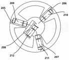
当所述的激光位移传感器为四个时,其中三个:第一激光位移传感器209、第二激光位移传感器210、第三激光位移传感器211各通过一个方形固定板205、方形固定板206、方形固定板207安装在连接盘204上,且沿着连接盘204的圆周方向三等分均布;第四激光位移传感器212通过L形固定板208安装在连接盘204上。When there are four laser displacement sensors, three of them: the first
激光位移传感器安装结构及作用分别为:The installation structure and functions of the laser displacement sensor are as follows:
1、方形固定板:包括方形固定板205、方形固定板206和方形固定板207:其上侧面上设有螺纹孔,用于与连接盘204的三个盘辐连接,其主面上设有通孔,用于分别与第一激光位移传感器209、第二激光位移传感器210和第三激光位移传感器211连接;1, square fixed plate: comprise square fixed
2、L形固定板208:其侧板上设有螺纹孔,用于与连接盘204连接,其主板上设有通孔,用于与第四激光位移传感器212连接;2. L-shaped fixing plate 208: the side plate is provided with threaded holes for connecting with the connecting
3、激光位移传感器:包括第一激光位移传感器209、第二激光位移传感器210、第三激光位移传感器211和第四激光位移传感器212,其侧面有两个用于固定的螺纹孔,其中第一激光位移传感器209、第二激光位移传感器210和第三激光位移传感器211用于分别与方形固定板205、方形固定板206和方形固定板207连接,第四激光位移传感器212与L形固定板208连接。3. Laser displacement sensor: including the first
四、标定球装置如图4所示:4. The calibration ball device is shown in Figure 4:
标定球装置3主要由三部分组成:标定球31、标定球连接柱32和底板33。所述的标定球31通过标定球连接柱32固定安装在标定球装置3的底板33上;所述的底板33在标定过程中分别固定于机械手工作空间中的多个不同位置上。The
标定球装置的结构及作用分别为:The structure and function of the calibration ball device are as follows:
1、标定球31:标定球31表面必须具备一定的球面度和表面粗糙度,同时半径r已知,另外其下方设有螺纹孔,用于与标定球连接柱32连接;1. Calibration ball 31: The surface of the
2、标定球连接柱32:标定球连接柱32上方的螺纹用于与标定球连接,下方的螺纹用于与底板33连接,上方螺纹与标定球连接柱的主体部分连接处有锥面进行过渡;2. Calibration ball connecting column 32: The upper thread of the calibration
3、底板33:底板33中心处设有螺纹孔,用于连接标定球连接柱32,另外,底板33四角设有光孔,用于固定整个标定球装置。3. Bottom plate 33: There is a threaded hole at the center of the
五、本发明的便携式六轴机械手标定装置的标定方法,其技术方案是(以四个激光位移传感器为例):5. The calibration method of the portable six-axis manipulator calibration device of the present invention, its technical solution is (taking four laser displacement sensors as an example):
标定传感装置2组装固定完成后,可对四个激光位移传感器默认坐标系之间的关系进行标定。After the
设定一个标定传感装置2的统一坐标系S;当操作机械手1、使四个激光位移传感器瞄准摆放在机械手1工作空间内的标定球31时,根据4个激光位移传感器的读数(d1,d2,d3,d4),以及已知的标定球31的半径r,可计算出标定球球心在标定球装置2统一坐标系S下的三维位置(x,y,z)。Set a unified coordinate system S of the
统一坐标系S可设置在4个激光位移传感器中的任一个的默认坐标系处,也可设置在其他任意位置。The unified coordinate system S can be set at the default coordinate system of any one of the four laser displacement sensors, and can also be set at any other position.
所述的标定方法的具体过程是:The concrete process of described calibration method is:
1、将所述的标定传感装置2固定安装在机械手末端法兰上;1. Fix the
2、将所述的标定球装置3固定安装在机械手1的工作空间内;2. Fix the
3、操作机械手1,使标定传感装置2上的四个激光位移传感器的激光束均能够打在标定球31上;同时,确保标定球31同时在四个激光位移传感器的工作距离内;此时,记录四个激光位移传感器的读数(d1,d2,d3,d4),根据标定球31的半径r,计算标定球球心在统一坐标系S下的坐标,同时记录机械手关节角位置(a1,a2,a3,a4,a5,a6);3. Operate the
4、保持标定球装置3不动,再次操作机械手1,使机械手处于其他关节位置,且同样使四个激光位移传感器的激光束能够打在标定球31上,记录此时四个激光位移传感器的读数,计算此时标定球31的球心在统一坐标系S下的坐标,同时记录机械手1关节角位置;4. Keep the
5、根据两次测量标定球31球心的机械手1的关节角位置,以及建立的机械手运动学模型,可以建立从机械手基坐标系B到标定传感装置2统一坐标系S的转换关系,并可将求出的标定球31球心坐标从标定传感装置2的S坐标系转换至机械手基坐标系B下的坐标;因为两次测量的标定球1球心坐标在机械手基坐标系B下的描述是不变的,因此可建立三个坐标转换等式;5. According to the joint angle position of the
6、更改标定球装置3在机械手1工作空间内的位置共m次,重复进行步骤3、步骤4和步骤5,则可建立3m个坐标转换等式;通过设定的数据处理方法,即可计算出机械手1的模型参数;6. Change the position of the
只需重复m次数足够大,使3m大于模型参数个数。It is only necessary to repeat m times large enough to make 3m greater than the number of model parameters.
六、本发明与现有技术公开文献的对比分析:Six, comparative analysis between the present invention and prior art publications:
1、关于现有技术文献:一种基于三维力传感器的工业机器人标定装置(201720566859.8);本发明与其获取辅助标定物的局部三维位置的方式不同,应用的传感器不同。1. Regarding the prior art literature: an industrial robot calibration device based on a three-dimensional force sensor (201720566859.8); the present invention is different from the way it acquires the local three-dimensional position of the auxiliary calibration object, and the sensors used are different.
该技术文献是基于三维力传感器获取辅助标定物的局部三维坐标,具体依靠测量球触碰标定球,根据检测得到的三维力信号,计算标定球球心在测量球局部坐标系下的三维坐标;而本发明是借助4个激光位移传感器,根据4个激光位移传感器的距离读数,计算标定球球心在激光位移传感器统一坐标系下的三维坐标。This technical document is based on the three-dimensional force sensor to obtain the local three-dimensional coordinates of the auxiliary calibration object, specifically relying on the measuring ball to touch the calibration ball, and according to the detected three-dimensional force signal, calculate the three-dimensional coordinates of the center of the calibration ball in the local coordinate system of the measuring ball; And the present invention calculates the three-dimensional coordinates of the center of the calibration ball under the unified coordinate system of the laser displacement sensors according to the distance readings of the four laser displacement sensors by means of the four laser displacement sensors.
在该技术文献中,检测标定球球心的三维坐标采用的是接触式方法;而本发明是检测标定球球心的三维坐标采用的是非接触式方法。In this technical document, a contact method is used to detect the three-dimensional coordinates of the center of the calibration ball; however, the present invention uses a non-contact method to detect the three-dimensional coordinates of the center of the calibration ball.
2、关于现有技术文献:一种工业机器人测量末端靶球快速定位装置(201720526966.8);该技术文献主要用于固定激光跟踪仪的靶球,必须和激光跟踪仪设备配套使用以实现机械手的标定;而本发明是一整套完备的用于机械手运动学参数标定的标定设备。2. About the existing technical literature: a rapid positioning device for the target ball at the end of the industrial robot measurement (201720526966.8); this technical literature is mainly used to fix the target ball of the laser tracker, and must be used in conjunction with the laser tracker equipment to realize the calibration of the manipulator ; And the present invention is a complete set of calibration equipment for calibration of manipulator kinematics parameters.
3、关于现有技术文献:一种用于工业机械手位置标定的三维定位装置(201710185981.5);该技术文献通过所属定位装置中的两个激光发射器以及X轴、Y轴和Z轴的运动,显式地计算机械手末端指定位置在外部测量坐标系下的三维位置;而本发明并未显式计算指定位置(标定球球心)在外部坐标系下的三维位置,只需建立关于此三维位置的约束等式。3. Regarding the existing technical documents: a three-dimensional positioning device for position calibration of industrial manipulators (201710185981.5); this technical document uses two laser transmitters in the positioning device and the movement of the X-axis, Y-axis and Z-axis, Explicitly calculate the three-dimensional position of the specified position of the end of the manipulator under the external measurement coordinate system; and the present invention does not explicitly calculate the three-dimensional position of the specified position (the center of the calibration ball) under the external coordinate system, only need to establish the three-dimensional position of this three-dimensional position constraint equation.
该技术文献的标定精度主要取决于所属定位装置各轴(X轴、Y轴和Z轴)的移动精度;而本发明的标定精度主要取决于激光位移传感器的精度。The calibration accuracy of this technical document mainly depends on the movement accuracy of each axis (X axis, Y axis and Z axis) of the positioning device; while the calibration accuracy of the present invention mainly depends on the accuracy of the laser displacement sensor.
七、本发明的技术创新点和技术关键点总结:Seven, technical innovation point and technical key point summary of the present invention:
1、采用4个激光位移传感器确定固定的标定球球心的三维坐标,采用4个激光位移传感器是确定一个标定球球心的最小数量,相对于激光跟踪仪和坐标测量机等测量设备,系统简单,成本低、便携性强、安装方便;1. Use 4 laser displacement sensors to determine the three-dimensional coordinates of the center of the fixed calibration ball. The use of 4 laser displacement sensors is to determine the minimum number of the center of a calibration ball. Compared with measuring equipment such as laser trackers and coordinate measuring machines, the system Simple, low cost, strong portability, easy installation;
2、采用4个激光位移传感器确定固定的标定球球心的三维坐标,确定标定示教点的方式更简单,只需4个激光位移传感器的激光束同时打在标定球上即可,示教简单,操作方便;2. Using 4 laser displacement sensors to determine the three-dimensional coordinates of the center of the fixed calibration ball, the way to determine the calibration teaching point is simpler. It only needs to hit the laser beams of the 4 laser displacement sensors on the calibration ball at the same time. Simple and easy to operate;
3、采用4个激光位移传感器的规格可变,标定球1的半径r可变,针对不同工作空间大小的机械手,可配置不同工作距离的激光位移传感器,以及不同半径的标定球,使标定设备在不同类型机械手上均可使用,即本标定设备应用范围广,可扩展性强。3. The specifications of the 4 laser displacement sensors are variable, and the radius r of the
八、本发明更具体的实施方式:Eight, the more specific embodiment of the present invention:
1、在本发明中,标定传感装置2中采用4个激光位移传感器测量标定球31的三维位置,这是所需激光位移传感器的最少个数,因此,多于4个的激光位移传感器配置也可应用于本发明,并可提供更高的测量精度;进而,如果标定传感装置2中的传感器是可以直接获得标定球的表面点云则也可直接应用于本发明,比如面结构光传感器、TOF相机等;1. In the present invention, four laser displacement sensors are used to measure the three-dimensional position of the
2、标定传感装置2中的4个激光位移传感器的安装位置可调,以适应不同半径大小的标定球;比如,对于较小半径的标定球,可调节4个激光位移传感器的安装位置使4个激光位移传感器所发射的激光束彼此之间的夹角更小,更方便标定示教点的确定;当然,对于较大半径的标定球,则可将4个激光位移传感器的光束之间的夹角调节的更大;2. The installation positions of the four laser displacement sensors in the
3、标定传感装置2中的连接法兰201可有多种周向通孔配置,以适应不同机械手末端法兰的安装要求;3. The
4、标定传感装置2中的4个激光位移传感器的精度可选用不同规格,以适应不同标定精度要求;4. The accuracy of the four laser displacement sensors in the
5、标定传感装置2中的4个激光位移传感器的工作距离也可选择不同规格,以适应不同机械手的不同工作区间大小;5. The working distances of the four laser displacement sensors in the
6、标定球装置3中的标定球31可采用不同半径,其球面的球面度、粗糙度等可配置不同规格以满足不同标定精度要求。6. The
上面结合附图对本发明进行了示例性描述,显然本发明具体实现并不受上述方式的限制,只要采用了本发明的方法构思和技术方案进行的各种非实质性的改进,或未经改进将本发明的构思和技术方案直接应用于其它场合的,均在本发明的保护范围之内。The present invention has been exemplarily described above in conjunction with the accompanying drawings. Obviously, the specific implementation of the present invention is not limited by the above methods, as long as various insubstantial improvements are adopted in the method concept and technical solutions of the present invention, or there is no improvement Directly applying the concept and technical solutions of the present invention to other occasions is within the protection scope of the present invention.
Claims (1)
Priority Applications (1)
| Application Number | Priority Date | Filing Date | Title |
|---|---|---|---|
| CN201911342593.9ACN110978059B (en) | 2019-12-23 | 2019-12-23 | A portable six-axis manipulator calibration device and calibration method thereof |
Applications Claiming Priority (1)
| Application Number | Priority Date | Filing Date | Title |
|---|---|---|---|
| CN201911342593.9ACN110978059B (en) | 2019-12-23 | 2019-12-23 | A portable six-axis manipulator calibration device and calibration method thereof |
Publications (2)
| Publication Number | Publication Date |
|---|---|
| CN110978059A CN110978059A (en) | 2020-04-10 |
| CN110978059Btrue CN110978059B (en) | 2022-12-23 |
Family
ID=70076126
Family Applications (1)
| Application Number | Title | Priority Date | Filing Date |
|---|---|---|---|
| CN201911342593.9AActiveCN110978059B (en) | 2019-12-23 | 2019-12-23 | A portable six-axis manipulator calibration device and calibration method thereof |
Country Status (1)
| Country | Link |
|---|---|
| CN (1) | CN110978059B (en) |
Families Citing this family (16)
| Publication number | Priority date | Publication date | Assignee | Title |
|---|---|---|---|---|
| CN113548443B (en)* | 2020-04-23 | 2022-03-25 | 上海微电子装备(集团)股份有限公司 | Detection method and detection device for manipulator handover |
| CN112361958B (en)* | 2020-11-04 | 2022-06-21 | 同济大学 | Line laser and mechanical arm calibration method |
| CN112720470B (en)* | 2020-12-18 | 2022-05-13 | 南京中科煜宸激光技术有限公司 | Mechanical arm TCP manual rapid calibration device and method for additive machining |
| CN112792817B (en)* | 2021-02-01 | 2025-07-04 | 中国建筑第八工程局有限公司 | Non-contact calibration device and method for robot arm workpiece coordinate system |
| CN112936341B (en)* | 2021-02-01 | 2022-05-20 | 威海威高骨科手术机器人有限公司 | Reset platform assembly process and calibration method |
| CN113084798B (en)* | 2021-03-16 | 2022-11-01 | 浙江大学湖州研究院 | A robot calibration device based on multi-station measurement |
| TWI762371B (en)* | 2021-07-06 | 2022-04-21 | 財團法人工業技術研究院 | Automated calibration system and method for the relation between a profile scanner coordinate frame and a robot arm coordinate frame |
| CN113510708B (en)* | 2021-07-28 | 2021-12-28 | 南京航空航天大学 | An automatic calibration system for contact-type industrial robots based on binocular vision |
| CN113878586B (en)* | 2021-11-04 | 2023-07-18 | 杭州景吾智能科技有限公司 | Robot kinematics calibration device, method and system |
| CN114043087B (en)* | 2021-12-03 | 2022-10-04 | 厦门大学 | A three-dimensional trajectory laser welding seam tracking attitude planning method |
| CN114536324B (en)* | 2022-01-11 | 2023-11-07 | 重庆智能机器人研究院 | Industrial robot automatic tool workpiece calibration method |
| CN114589730A (en)* | 2022-02-25 | 2022-06-07 | 埃夫特智能装备股份有限公司 | A contact calibration tool for robots |
| CN115265358A (en)* | 2022-06-17 | 2022-11-01 | 上海景吾酷租科技发展有限公司 | Robot repeated positioning precision measuring device and method |
| CN115946124B (en)* | 2023-02-09 | 2025-07-08 | 上海发那科机器人有限公司 | Method for calibrating pose relation between robot and turntable by using laser tracker |
| CN117644306B (en)* | 2024-01-30 | 2024-05-03 | 武汉新耐视智能科技有限责任公司 | Focus detection device and method for robot laser remote welding equipment |
| CN119304346B (en)* | 2024-12-18 | 2025-04-04 | 浙江摩克激光智能装备有限公司 | Three-dimensional curved surface workpiece calibration method and device of laser processing robot |
Citations (7)
| Publication number | Priority date | Publication date | Assignee | Title |
|---|---|---|---|---|
| BE1010211A6 (en)* | 1996-05-14 | 1998-03-03 | Den Bossche Johan Van | Method for programming a robot by means of external coordinate measuring system and manual probe |
| CN105058387A (en)* | 2015-07-17 | 2015-11-18 | 北京航空航天大学 | Industrial robot base coordinate system calibration method based on laser tracker |
| CN107042527A (en)* | 2017-05-20 | 2017-08-15 | 天津大学 | A kind of industrial robot caliberating device and scaling method based on three-dimensional force sensor |
| CN107560538A (en)* | 2017-08-17 | 2018-01-09 | 安徽零点精密机械有限责任公司 | The scaling method of six-DOF robot tool coordinates system based on laser tracker |
| CN107738254A (en)* | 2017-08-25 | 2018-02-27 | 中国科学院光电研究院 | The conversion scaling method and system of a kind of mechanical arm coordinate system |
| CN109571546A (en)* | 2017-09-29 | 2019-04-05 | 财团法人工业技术研究院 | Robot tool center point correction system and method thereof |
| CN109676636A (en)* | 2019-03-06 | 2019-04-26 | 南京航空航天大学 | A kind of industrial robot kinematics calibration system and scaling method |
- 2019
- 2019-12-23CNCN201911342593.9Apatent/CN110978059B/enactiveActive
Patent Citations (7)
| Publication number | Priority date | Publication date | Assignee | Title |
|---|---|---|---|---|
| BE1010211A6 (en)* | 1996-05-14 | 1998-03-03 | Den Bossche Johan Van | Method for programming a robot by means of external coordinate measuring system and manual probe |
| CN105058387A (en)* | 2015-07-17 | 2015-11-18 | 北京航空航天大学 | Industrial robot base coordinate system calibration method based on laser tracker |
| CN107042527A (en)* | 2017-05-20 | 2017-08-15 | 天津大学 | A kind of industrial robot caliberating device and scaling method based on three-dimensional force sensor |
| CN107560538A (en)* | 2017-08-17 | 2018-01-09 | 安徽零点精密机械有限责任公司 | The scaling method of six-DOF robot tool coordinates system based on laser tracker |
| CN107738254A (en)* | 2017-08-25 | 2018-02-27 | 中国科学院光电研究院 | The conversion scaling method and system of a kind of mechanical arm coordinate system |
| CN109571546A (en)* | 2017-09-29 | 2019-04-05 | 财团法人工业技术研究院 | Robot tool center point correction system and method thereof |
| CN109676636A (en)* | 2019-03-06 | 2019-04-26 | 南京航空航天大学 | A kind of industrial robot kinematics calibration system and scaling method |
Non-Patent Citations (4)
| Title |
|---|
| 基于激光测距传感器的机械臂运动学参数标定;徐艳华等;《激光杂志》;20180825(第08期);第105-108页* |
| 机器人定点变位姿手-眼标定方法;王胜华等;《清华大学学报(自然科学版)》;20070225(第02期);第165-168页* |
| 机器人末端位移传感器的安装位置标定方法;袁康正等;《浙江大学学报(工学版)》;20150515(第05期);第105-108页* |
| 激光跟踪仪与机器人坐标系转换方法研究;向民志等;《航空制造技术》;20180115;第98-101页* |
Also Published As
| Publication number | Publication date |
|---|---|
| CN110978059A (en) | 2020-04-10 |
Similar Documents
| Publication | Publication Date | Title |
|---|---|---|
| CN110978059B (en) | A portable six-axis manipulator calibration device and calibration method thereof | |
| CN107042528B (en) | Kinematics calibration system and method for industrial robot | |
| WO2021238617A1 (en) | Industrial robot absolute precision calibration system and method | |
| CN102506702B (en) | Large three-dimensional coordinate measuring method with laser tracking and device | |
| CN110500978B (en) | Light beam direction vector and zero point position on-line calibration method of point laser sensor | |
| CN101272887B (en) | Method and apparatus for measurement and/or calibration of position of an object in space | |
| CN105865341B (en) | Industrial robot spatial pose repetitive positioning accuracy measuring device and method | |
| CN111366070B (en) | A calibration method for multi-axis space coordinate system of composite line laser measurement system | |
| CN102654387B (en) | Online industrial robot calibration device based on spatial curved surface restraint | |
| CN107462881A (en) | A kind of laser range sensor scaling method | |
| CN111964589B (en) | A laser displacement sensor calibration device and calibration method for normal detection | |
| CN101660904A (en) | Kinematics calibration method of measurement robot | |
| CN208968469U (en) | Industrial robot repeated positioning precision analysis system | |
| CN113146613B (en) | An industrial robot D-H parameter three-dimensional self-calibration calibration device and method | |
| CN115284079B (en) | Magnetorheological polishing calibration method | |
| CN110893619A (en) | Industrial robot position appearance calibrating device based on laser tracker | |
| CN112288823A (en) | A calibration method of standard cylinder surface point measuring equipment | |
| CN115371564B (en) | Method and system for calibrating relative pose between line laser sensor and robot flange | |
| CN113513986A (en) | Geometric tolerance measuring device and measuring method thereof | |
| CN113878586B (en) | Robot kinematics calibration device, method and system | |
| CN216846033U (en) | Inner wall measurement system based on deep sagittal workpiece | |
| CN114295051B (en) | Automatic positioning device and method for harmonic coil magnetic field measurement | |
| CN109059768B (en) | Pose calibration method for container built-in part detection system | |
| CN114018174B (en) | Complex curved surface contour measuring system | |
| TW201509617A (en) | Robot arm precision measurement system and measuring method thereof |
Legal Events
| Date | Code | Title | Description |
|---|---|---|---|
| PB01 | Publication | ||
| PB01 | Publication | ||
| SE01 | Entry into force of request for substantive examination | ||
| SE01 | Entry into force of request for substantive examination | ||
| GR01 | Patent grant | ||
| GR01 | Patent grant |