CN110966427A - Water diversion device - Google Patents
Water diversion deviceDownload PDFInfo
- Publication number
- CN110966427A CN110966427ACN201911395792.6ACN201911395792ACN110966427ACN 110966427 ACN110966427 ACN 110966427ACN 201911395792 ACN201911395792 ACN 201911395792ACN 110966427 ACN110966427 ACN 110966427A
- Authority
- CN
- China
- Prior art keywords
- valve core
- water
- movable valve
- water outlet
- static
- Prior art date
- Legal status (The legal status is an assumption and is not a legal conclusion. Google has not performed a legal analysis and makes no representation as to the accuracy of the status listed.)
- Pending
Links
Images


Classifications
- F—MECHANICAL ENGINEERING; LIGHTING; HEATING; WEAPONS; BLASTING
- F16—ENGINEERING ELEMENTS AND UNITS; GENERAL MEASURES FOR PRODUCING AND MAINTAINING EFFECTIVE FUNCTIONING OF MACHINES OR INSTALLATIONS; THERMAL INSULATION IN GENERAL
- F16K—VALVES; TAPS; COCKS; ACTUATING-FLOATS; DEVICES FOR VENTING OR AERATING
- F16K11/00—Multiple-way valves, e.g. mixing valves; Pipe fittings incorporating such valves
- F16K11/02—Multiple-way valves, e.g. mixing valves; Pipe fittings incorporating such valves with all movable sealing faces moving as one unit
- F16K11/04—Multiple-way valves, e.g. mixing valves; Pipe fittings incorporating such valves with all movable sealing faces moving as one unit comprising only lift valves
- F16K11/044—Multiple-way valves, e.g. mixing valves; Pipe fittings incorporating such valves with all movable sealing faces moving as one unit comprising only lift valves with movable valve members positioned between valve seats
- F—MECHANICAL ENGINEERING; LIGHTING; HEATING; WEAPONS; BLASTING
- F16—ENGINEERING ELEMENTS AND UNITS; GENERAL MEASURES FOR PRODUCING AND MAINTAINING EFFECTIVE FUNCTIONING OF MACHINES OR INSTALLATIONS; THERMAL INSULATION IN GENERAL
- F16K—VALVES; TAPS; COCKS; ACTUATING-FLOATS; DEVICES FOR VENTING OR AERATING
- F16K31/00—Actuating devices; Operating means; Releasing devices
- F16K31/44—Mechanical actuating means
- F16K31/60—Handles
- F16K31/605—Handles for single handle mixing valves
Landscapes
- Engineering & Computer Science (AREA)
- General Engineering & Computer Science (AREA)
- Mechanical Engineering (AREA)
- Lift Valve (AREA)
Abstract
Translated fromChinese
Description
Claims (10)
Priority Applications (1)
| Application Number | Priority Date | Filing Date | Title |
|---|---|---|---|
| CN201911395792.6ACN110966427A (en) | 2019-12-30 | 2019-12-30 | Water diversion device |
Applications Claiming Priority (1)
| Application Number | Priority Date | Filing Date | Title |
|---|---|---|---|
| CN201911395792.6ACN110966427A (en) | 2019-12-30 | 2019-12-30 | Water diversion device |
Publications (1)
| Publication Number | Publication Date |
|---|---|
| CN110966427Atrue CN110966427A (en) | 2020-04-07 |
Family
ID=70037355
Family Applications (1)
| Application Number | Title | Priority Date | Filing Date |
|---|---|---|---|
| CN201911395792.6APendingCN110966427A (en) | 2019-12-30 | 2019-12-30 | Water diversion device |
Country Status (1)
| Country | Link |
|---|---|
| CN (1) | CN110966427A (en) |
Cited By (1)
| Publication number | Priority date | Publication date | Assignee | Title |
|---|---|---|---|---|
| CN114110245A (en)* | 2021-11-26 | 2022-03-01 | 路达(厦门)工业有限公司 | Novel switch structure and water outlet device |
Citations (5)
| Publication number | Priority date | Publication date | Assignee | Title |
|---|---|---|---|---|
| CN2460815Y (en)* | 2000-12-22 | 2001-11-21 | 杨方华 | Improved cerimic spool |
| CN103697193A (en)* | 2013-12-17 | 2014-04-02 | 谢尚锦 | Openly-mounted two-inlet and two-outlet tap |
| US20140102574A1 (en)* | 2012-10-11 | 2014-04-17 | Geann Industrial Co., Ltd. | Water valve suitable for use with a bathtub |
| CN110440029A (en)* | 2019-07-09 | 2019-11-12 | 李良清 | Rocker-arm is classified tap and its spool |
| CN211231690U (en)* | 2019-12-30 | 2020-08-11 | 温州联迎科技有限公司 | Water diversion device |
- 2019
- 2019-12-30CNCN201911395792.6Apatent/CN110966427A/enactivePending
Patent Citations (5)
| Publication number | Priority date | Publication date | Assignee | Title |
|---|---|---|---|---|
| CN2460815Y (en)* | 2000-12-22 | 2001-11-21 | 杨方华 | Improved cerimic spool |
| US20140102574A1 (en)* | 2012-10-11 | 2014-04-17 | Geann Industrial Co., Ltd. | Water valve suitable for use with a bathtub |
| CN103697193A (en)* | 2013-12-17 | 2014-04-02 | 谢尚锦 | Openly-mounted two-inlet and two-outlet tap |
| CN110440029A (en)* | 2019-07-09 | 2019-11-12 | 李良清 | Rocker-arm is classified tap and its spool |
| CN211231690U (en)* | 2019-12-30 | 2020-08-11 | 温州联迎科技有限公司 | Water diversion device |
Cited By (1)
| Publication number | Priority date | Publication date | Assignee | Title |
|---|---|---|---|---|
| CN114110245A (en)* | 2021-11-26 | 2022-03-01 | 路达(厦门)工业有限公司 | Novel switch structure and water outlet device |
Similar Documents
| Publication | Publication Date | Title |
|---|---|---|
| US10239065B2 (en) | Flow control component and shower | |
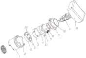
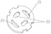
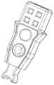
| CN110966427A (en) | Water diversion device | |
| CN110131435B (en) | Electric plug valve | |
| CN211231690U (en) | Water diversion device | |
| CN201013965Y (en) | Rocker faucet spool | |
| CN114183547A (en) | Electronic expansion valve | |
| CN111871629B (en) | Water outlet switching mechanism of shower head | |
| CN111963704B (en) | A temperature-switchable ceramic valve core | |
| US9238236B2 (en) | Waterway switch valve set and a shower head using same | |
| CN110624705B (en) | Gondola water faucet stagnant water structure and gondola water faucet subassembly | |
| JP2011201029A (en) | Mold | |
| CN101786052B (en) | Shower head of slide body | |
| CN220371315U (en) | Water outlet state adjusting device and shower head | |
| CN215612425U (en) | Shower head with single switch for switching and controlling water outlet | |
| CN211398655U (en) | Faucet structure with spray gun | |
| CN215843652U (en) | Water outlet switching mechanism of shower head | |
| CN215334635U (en) | Switching valve core and shower valve | |
| CN212839411U (en) | A control valve and its water outlet device | |
| CN220870149U (en) | Pressing switching valve core | |
| CN218063519U (en) | Linkage water diversion switch device | |
| CN210290814U (en) | Quick-opening valve device | |
| CN218294664U (en) | Connection structure of a plurality of buttons of shower faucet | |
| CN110848418A (en) | Faucet structure with spray gun | |
| CN201565373U (en) | Sliding shower head | |
| CN219827816U (en) | Multi-key water diversion valve core and water outlet device |
Legal Events
| Date | Code | Title | Description |
|---|---|---|---|
| PB01 | Publication | ||
| PB01 | Publication | ||
| SE01 | Entry into force of request for substantive examination | ||
| SE01 | Entry into force of request for substantive examination | ||
| TA01 | Transfer of patent application right | Effective date of registration:20200624 Address after:325000 No.10, Daizhong Road, Haicheng street, Wenzhou Economic and Technological Development Zone, Wenzhou City, Zhejiang Province Applicant after:Wenzhou Lianying Technology Co.,Ltd. Address before:325000 No.10, Daizhong Road, Haicheng street, Wenzhou Economic and Technological Development Zone, Wenzhou City, Zhejiang Province Applicant before:Wenzhou Xinyi Sanitary Ware Co.,Ltd. | |
| TA01 | Transfer of patent application right | ||
| TA01 | Transfer of patent application right | Effective date of registration:20220921 Address after:No. 22-9, Luomei Avenue, Haicheng Street, Economic and Technological Development Zone, Wenzhou City, Zhejiang Province, 325000 Applicant after:Wenzhou yuebo valve core Co.,Ltd. Address before:No. 10, Daizhong Road, Haicheng Street, Wenzhou Economic and Technological Development Zone, Wenzhou City, Zhejiang Province, 325000 Applicant before:Wenzhou Lianying Technology Co.,Ltd. | |
| TA01 | Transfer of patent application right | ||
| WD01 | Invention patent application deemed withdrawn after publication | Application publication date:20200407 | |
| WD01 | Invention patent application deemed withdrawn after publication |