CN110962692B - Battery pack heating system and control method thereof - Google Patents
Battery pack heating system and control method thereofDownload PDFInfo
- Publication number
- CN110962692B CN110962692BCN201910547455.8ACN201910547455ACN110962692BCN 110962692 BCN110962692 BCN 110962692BCN 201910547455 ACN201910547455 ACN 201910547455ACN 110962692 BCN110962692 BCN 110962692B
- Authority
- CN
- China
- Prior art keywords
- battery pack
- motor
- switch
- heating
- temperature
- Prior art date
- Legal status (The legal status is an assumption and is not a legal conclusion. Google has not performed a legal analysis and makes no representation as to the accuracy of the status listed.)
- Active
Links
Images


Classifications
- B—PERFORMING OPERATIONS; TRANSPORTING
- B60—VEHICLES IN GENERAL
- B60L—PROPULSION OF ELECTRICALLY-PROPELLED VEHICLES; SUPPLYING ELECTRIC POWER FOR AUXILIARY EQUIPMENT OF ELECTRICALLY-PROPELLED VEHICLES; ELECTRODYNAMIC BRAKE SYSTEMS FOR VEHICLES IN GENERAL; MAGNETIC SUSPENSION OR LEVITATION FOR VEHICLES; MONITORING OPERATING VARIABLES OF ELECTRICALLY-PROPELLED VEHICLES; ELECTRIC SAFETY DEVICES FOR ELECTRICALLY-PROPELLED VEHICLES
- B60L58/00—Methods or circuit arrangements for monitoring or controlling batteries or fuel cells, specially adapted for electric vehicles
- B60L58/10—Methods or circuit arrangements for monitoring or controlling batteries or fuel cells, specially adapted for electric vehicles for monitoring or controlling batteries
- B60L58/24—Methods or circuit arrangements for monitoring or controlling batteries or fuel cells, specially adapted for electric vehicles for monitoring or controlling batteries for controlling the temperature of batteries
- B60L58/27—Methods or circuit arrangements for monitoring or controlling batteries or fuel cells, specially adapted for electric vehicles for monitoring or controlling batteries for controlling the temperature of batteries by heating
- B—PERFORMING OPERATIONS; TRANSPORTING
- B60—VEHICLES IN GENERAL
- B60L—PROPULSION OF ELECTRICALLY-PROPELLED VEHICLES; SUPPLYING ELECTRIC POWER FOR AUXILIARY EQUIPMENT OF ELECTRICALLY-PROPELLED VEHICLES; ELECTRODYNAMIC BRAKE SYSTEMS FOR VEHICLES IN GENERAL; MAGNETIC SUSPENSION OR LEVITATION FOR VEHICLES; MONITORING OPERATING VARIABLES OF ELECTRICALLY-PROPELLED VEHICLES; ELECTRIC SAFETY DEVICES FOR ELECTRICALLY-PROPELLED VEHICLES
- B60L58/00—Methods or circuit arrangements for monitoring or controlling batteries or fuel cells, specially adapted for electric vehicles
- B60L58/10—Methods or circuit arrangements for monitoring or controlling batteries or fuel cells, specially adapted for electric vehicles for monitoring or controlling batteries
- B60L58/12—Methods or circuit arrangements for monitoring or controlling batteries or fuel cells, specially adapted for electric vehicles for monitoring or controlling batteries responding to state of charge [SoC]
- H—ELECTRICITY
- H01—ELECTRIC ELEMENTS
- H01M—PROCESSES OR MEANS, e.g. BATTERIES, FOR THE DIRECT CONVERSION OF CHEMICAL ENERGY INTO ELECTRICAL ENERGY
- H01M10/00—Secondary cells; Manufacture thereof
- H01M10/42—Methods or arrangements for servicing or maintenance of secondary cells or secondary half-cells
- H01M10/425—Structural combination with electronic components, e.g. electronic circuits integrated to the outside of the casing
- H—ELECTRICITY
- H01—ELECTRIC ELEMENTS
- H01M—PROCESSES OR MEANS, e.g. BATTERIES, FOR THE DIRECT CONVERSION OF CHEMICAL ENERGY INTO ELECTRICAL ENERGY
- H01M10/00—Secondary cells; Manufacture thereof
- H01M10/60—Heating or cooling; Temperature control
- H01M10/61—Types of temperature control
- H01M10/615—Heating or keeping warm
- H—ELECTRICITY
- H01—ELECTRIC ELEMENTS
- H01M—PROCESSES OR MEANS, e.g. BATTERIES, FOR THE DIRECT CONVERSION OF CHEMICAL ENERGY INTO ELECTRICAL ENERGY
- H01M10/00—Secondary cells; Manufacture thereof
- H01M10/60—Heating or cooling; Temperature control
- H01M10/62—Heating or cooling; Temperature control specially adapted for specific applications
- H01M10/625—Vehicles
- H—ELECTRICITY
- H01—ELECTRIC ELEMENTS
- H01M—PROCESSES OR MEANS, e.g. BATTERIES, FOR THE DIRECT CONVERSION OF CHEMICAL ENERGY INTO ELECTRICAL ENERGY
- H01M10/00—Secondary cells; Manufacture thereof
- H01M10/60—Heating or cooling; Temperature control
- H01M10/63—Control systems
- H—ELECTRICITY
- H01—ELECTRIC ELEMENTS
- H01M—PROCESSES OR MEANS, e.g. BATTERIES, FOR THE DIRECT CONVERSION OF CHEMICAL ENERGY INTO ELECTRICAL ENERGY
- H01M10/00—Secondary cells; Manufacture thereof
- H01M10/60—Heating or cooling; Temperature control
- H01M10/63—Control systems
- H01M10/633—Control systems characterised by algorithms, flow charts, software details or the like
- H—ELECTRICITY
- H01—ELECTRIC ELEMENTS
- H01M—PROCESSES OR MEANS, e.g. BATTERIES, FOR THE DIRECT CONVERSION OF CHEMICAL ENERGY INTO ELECTRICAL ENERGY
- H01M10/00—Secondary cells; Manufacture thereof
- H01M10/60—Heating or cooling; Temperature control
- H01M10/65—Means for temperature control structurally associated with the cells
- H01M10/657—Means for temperature control structurally associated with the cells by electric or electromagnetic means
- H—ELECTRICITY
- H01—ELECTRIC ELEMENTS
- H01M—PROCESSES OR MEANS, e.g. BATTERIES, FOR THE DIRECT CONVERSION OF CHEMICAL ENERGY INTO ELECTRICAL ENERGY
- H01M10/00—Secondary cells; Manufacture thereof
- H01M10/60—Heating or cooling; Temperature control
- H01M10/66—Heat-exchange relationships between the cells and other systems, e.g. central heating systems or fuel cells
- B—PERFORMING OPERATIONS; TRANSPORTING
- B60—VEHICLES IN GENERAL
- B60L—PROPULSION OF ELECTRICALLY-PROPELLED VEHICLES; SUPPLYING ELECTRIC POWER FOR AUXILIARY EQUIPMENT OF ELECTRICALLY-PROPELLED VEHICLES; ELECTRODYNAMIC BRAKE SYSTEMS FOR VEHICLES IN GENERAL; MAGNETIC SUSPENSION OR LEVITATION FOR VEHICLES; MONITORING OPERATING VARIABLES OF ELECTRICALLY-PROPELLED VEHICLES; ELECTRIC SAFETY DEVICES FOR ELECTRICALLY-PROPELLED VEHICLES
- B60L2240/00—Control parameters of input or output; Target parameters
- B60L2240/40—Drive Train control parameters
- B60L2240/54—Drive Train control parameters related to batteries
- B60L2240/545—Temperature
- H—ELECTRICITY
- H01—ELECTRIC ELEMENTS
- H01M—PROCESSES OR MEANS, e.g. BATTERIES, FOR THE DIRECT CONVERSION OF CHEMICAL ENERGY INTO ELECTRICAL ENERGY
- H01M10/00—Secondary cells; Manufacture thereof
- H01M10/42—Methods or arrangements for servicing or maintenance of secondary cells or secondary half-cells
- H01M10/425—Structural combination with electronic components, e.g. electronic circuits integrated to the outside of the casing
- H01M2010/4271—Battery management systems including electronic circuits, e.g. control of current or voltage to keep battery in healthy state, cell balancing
- H—ELECTRICITY
- H01—ELECTRIC ELEMENTS
- H01M—PROCESSES OR MEANS, e.g. BATTERIES, FOR THE DIRECT CONVERSION OF CHEMICAL ENERGY INTO ELECTRICAL ENERGY
- H01M2220/00—Batteries for particular applications
- H01M2220/20—Batteries in motive systems, e.g. vehicle, ship, plane
- Y—GENERAL TAGGING OF NEW TECHNOLOGICAL DEVELOPMENTS; GENERAL TAGGING OF CROSS-SECTIONAL TECHNOLOGIES SPANNING OVER SEVERAL SECTIONS OF THE IPC; TECHNICAL SUBJECTS COVERED BY FORMER USPC CROSS-REFERENCE ART COLLECTIONS [XRACs] AND DIGESTS
- Y02—TECHNOLOGIES OR APPLICATIONS FOR MITIGATION OR ADAPTATION AGAINST CLIMATE CHANGE
- Y02T—CLIMATE CHANGE MITIGATION TECHNOLOGIES RELATED TO TRANSPORTATION
- Y02T90/00—Enabling technologies or technologies with a potential or indirect contribution to GHG emissions mitigation
- Y02T90/10—Technologies relating to charging of electric vehicles
- Y02T90/12—Electric charging stations
- Y—GENERAL TAGGING OF NEW TECHNOLOGICAL DEVELOPMENTS; GENERAL TAGGING OF CROSS-SECTIONAL TECHNOLOGIES SPANNING OVER SEVERAL SECTIONS OF THE IPC; TECHNICAL SUBJECTS COVERED BY FORMER USPC CROSS-REFERENCE ART COLLECTIONS [XRACs] AND DIGESTS
- Y02—TECHNOLOGIES OR APPLICATIONS FOR MITIGATION OR ADAPTATION AGAINST CLIMATE CHANGE
- Y02T—CLIMATE CHANGE MITIGATION TECHNOLOGIES RELATED TO TRANSPORTATION
- Y02T90/00—Enabling technologies or technologies with a potential or indirect contribution to GHG emissions mitigation
- Y02T90/10—Technologies relating to charging of electric vehicles
- Y02T90/16—Information or communication technologies improving the operation of electric vehicles
Landscapes
- Engineering & Computer Science (AREA)
- Electrochemistry (AREA)
- General Chemical & Material Sciences (AREA)
- Manufacturing & Machinery (AREA)
- Chemical & Material Sciences (AREA)
- Chemical Kinetics & Catalysis (AREA)
- Sustainable Energy (AREA)
- Life Sciences & Earth Sciences (AREA)
- Sustainable Development (AREA)
- Power Engineering (AREA)
- Transportation (AREA)
- Mechanical Engineering (AREA)
- Automation & Control Theory (AREA)
- Electromagnetism (AREA)
- Physics & Mathematics (AREA)
- Microelectronics & Electronic Packaging (AREA)
- Electric Propulsion And Braking For Vehicles (AREA)
- Secondary Cells (AREA)
- Charge And Discharge Circuits For Batteries Or The Like (AREA)
Abstract
Description
Translated fromChinese技术领域technical field
本发明属于电池技术领域,尤其涉及一种电池组加热系统及其控制方法。The invention belongs to the technical field of batteries, and in particular relates to a battery pack heating system and a control method thereof.
背景技术Background technique
随着新能源的发展,越来越多的领域采用新能源作为动力。由于具有能量密度高、可循环充电、安全环保等优点,电池被广泛应用于新能源汽车、消费电子、储能系统等领域中。With the development of new energy, more and more fields use new energy as power. Due to the advantages of high energy density, recyclable charging, safety and environmental protection, batteries are widely used in new energy vehicles, consumer electronics, energy storage systems and other fields.
但是低温环境下电池的使用会受到一定限制。具体的,电池在低温环境下的放电容量会严重衰退,以及电池在低温环境下无法充电。因此,为了能够正常使用电池,需要在低温环境下为电池进行加热。However, the use of batteries in low temperature environments will be limited. Specifically, the discharge capacity of the battery in a low temperature environment will be seriously degraded, and the battery cannot be charged in a low temperature environment. Therefore, in order to use the battery normally, it is necessary to heat the battery in a low temperature environment.
现阶段,可通过为电池配备专门的热循环容器,通过间接加热热循环容器中的导热物质,将热量传导到电池上,以实现对电池的加热。但是这种加热方式所花费的时间较长,加热效率较低。At this stage, the battery can be heated by equipping the battery with a special thermal cycle container and indirectly heating the thermally conductive material in the thermal cycle container to conduct heat to the battery. However, this heating method takes a long time and the heating efficiency is low.
发明内容SUMMARY OF THE INVENTION
本发明实施例提供了一种电池组加热系统及其控制方法,能够提高对电池组的加热效率。Embodiments of the present invention provide a battery pack heating system and a control method thereof, which can improve the heating efficiency of the battery pack.
第一方面,本发明实施例提供了一种电池组加热系统,包括与电池组的正极连接的主正开关、与电池组的负极连接的主负开关、与主正开关和主负开关连接的逆变器、与逆变器连接的外接端口、与逆变器连接的电机,以及辅助充电支路控制模块、整车控制器、电机控制器和电池管理模块;逆变器包括多个开关模块;外接端口连接辅助充电支路,辅助充电支路包括供电电源;电池管理模块用于获取电池组的状态参数,若电池组的状态参数满足预设低温低电量条件,向整车控制器和辅助充电支路控制模块分别发送低温低电量加热请求指令;辅助充电支路控制模块用于响应低温低电量加热请求指令,向辅助充电支路发送第一控制信号,以控制电池组加热系统与辅助充电支路导通,使得供电电源通过外接端口向电池组和/或电机传输能量;整车控制器用于响应低温低电量加热请求指令,向电机控制器发送第二控制信号,使电机控制器控制逆变器中的开关模块的通断,向电池管理模块发送第三控制信号,使电池管理模块控制主正开关的通断,使电池组与电机之间相互传递能量,以对电池组进行加热。In a first aspect, an embodiment of the present invention provides a battery pack heating system, including a main positive switch connected to the positive pole of the battery pack, a main negative switch connected to the negative pole of the battery pack, and a main positive switch and the main negative switch. Inverter, external port connected to the inverter, motor connected to the inverter, and auxiliary charging branch control module, vehicle controller, motor controller and battery management module; the inverter includes multiple switch modules ;The external port is connected to the auxiliary charging branch, and the auxiliary charging branch includes the power supply; the battery management module is used to obtain the state parameters of the battery pack. The charging branch control module sends low-temperature and low-battery heating request commands respectively; the auxiliary charging branch control module is used to respond to the low-temperature and low-battery heating request commands, and send a first control signal to the auxiliary charging branch to control the battery pack heating system and auxiliary charging. The branch is turned on, so that the power supply transmits energy to the battery pack and/or the motor through the external port; the vehicle controller is used to respond to the low temperature and low battery heating request command, and send a second control signal to the motor controller, so that the motor controller controls the reverse. The switch module in the inverter is turned on and off, and a third control signal is sent to the battery management module, so that the battery management module controls the on-off of the main positive switch, so that the battery pack and the motor transfer energy to each other to heat the battery pack.
第二方面,本发明实施例提供了一种电池组加热系统的控制方法,应用于第一方面中的电池组加热系统,电池组加热系统的控制方法包括:电池管理模块获取电池组的状态参数,若电池组的状态参数满足预设低温低电量条件,向整车控制器和辅助充电支路控制模块分别发送低温低电量加热请求指令;辅助充电支路控制模块响应低温低电量加热请求指令,向辅助充电支路发送第一控制信号,以控制电池组加热系统与辅助充电支路导通,使得供电电源通过外接端口向电池组和/或电机传输能量;整车控制器响应低温低电量加热请求指令,向电机控制器发送第二控制信号,使电机控制器控制逆变器中的开关模块的通断,向电池管理模块发送第三控制信号,使电池管理模块控制主正开关的通断,使电池组与电机之间相互传递能量,以对电池组进行加热。In a second aspect, an embodiment of the present invention provides a control method for a battery pack heating system, which is applied to the battery pack heating system in the first aspect. The control method for the battery pack heating system includes: a battery management module obtains a state parameter of the battery pack , if the state parameters of the battery pack meet the preset low temperature and low battery conditions, send a low temperature and low battery heating request command to the vehicle controller and the auxiliary charging branch control module respectively; the auxiliary charging branch control module responds to the low temperature and low battery heating request command, Send a first control signal to the auxiliary charging branch to control the conduction between the battery pack heating system and the auxiliary charging branch, so that the power supply transmits energy to the battery pack and/or the motor through the external port; the vehicle controller responds to low temperature and low battery heating Request command, send a second control signal to the motor controller, so that the motor controller controls the on-off of the switch module in the inverter, and send a third control signal to the battery management module, so that the battery management module controls the on-off of the main positive switch , to transfer energy between the battery pack and the motor to heat the battery pack.
本发明实施例提供了一种电池组加热系统及其控制方法,电池管理模块确定电池组的状态参数满足预设低温低电量条件,向整车控制器和辅助充电支路控制模块分别发送低温低电量加热请求指令,以请求进行低温低电量加热模式。电池管理模块通过控制辅助充电支路控制模块,整车控制器通过控制电池管理模块和电机控制器,控制辅助充电支路、主正开关和逆变器中的开关模块,使辅助充电支路中供电电源向电池组和/或电机传输能量,以使电池组和电机具有充足的可支持对电池组加热的能量。电池组与电机之间相互传递能量,形成电池组充、放电的循环,在电池组所在的回路中产生电流。交流电流可连续不断的通过电池组,使得电池组的内阻发热,从而在低电量的情况下也可实现对电池组的均匀、高效率的自加热。The embodiments of the present invention provide a battery pack heating system and a control method thereof. The battery management module determines that the state parameters of the battery pack meet the preset low temperature and low battery conditions, and sends a low temperature low battery signal to the vehicle controller and the auxiliary charging branch control module respectively. Power heating request command to request low temperature and low power heating mode. The battery management module controls the auxiliary charging branch control module, and the vehicle controller controls the auxiliary charging branch, the main positive switch and the switch module in the inverter by controlling the battery management module and the motor controller, so that the auxiliary charging branch can be controlled. The power supply transmits energy to the battery pack and/or the motor so that the battery pack and the motor have sufficient energy to support heating of the battery pack. The battery pack and the motor transfer energy to each other, forming a cycle of charging and discharging the battery pack, and generating current in the circuit where the battery pack is located. The alternating current can continuously pass through the battery pack, causing the internal resistance of the battery pack to generate heat, so that even and high-efficiency self-heating of the battery pack can be achieved even in the case of low power.
附图说明Description of drawings
从下面结合附图对本发明的具体实施方式的描述中可以更好地理解本发明,其中,相同或相似的附图标记表示相同或相似的特征。The present invention can be better understood from the following description of specific embodiments of the invention in conjunction with the accompanying drawings, wherein the same or similar reference numerals refer to the same or similar features.
图1为本发明一实施例中一种电池组加热系统的结构示意图;FIG. 1 is a schematic structural diagram of a battery pack heating system according to an embodiment of the present invention;
图2为本发明另一实施例中一种电池组加热系统的结构示意图;2 is a schematic structural diagram of a battery pack heating system in another embodiment of the present invention;
图3为本发明实施例中一种电池组加热系统的控制方法的流程图;3 is a flowchart of a control method of a battery pack heating system in an embodiment of the present invention;
图4为本发明另一实施例中一种电池组加热系统的控制方法的流程图;4 is a flowchart of a control method of a battery pack heating system in another embodiment of the present invention;
图5为本发明又一实施例中一种电池组加热系统的控制方法的流程图。FIG. 5 is a flowchart of a control method of a battery pack heating system in another embodiment of the present invention.
具体实施方式Detailed ways
下面将详细描述本发明的各个方面的特征和示例性实施例。在下面的详细描述中,提出了许多具体细节,以便提供对本发明的全面理解。但是,对于本领域技术人员来说很明显的是,本发明可以在不需要这些具体细节中的一些细节的情况下实施。下面对实施例的描述仅仅是为了通过示出本发明的示例来提供对本发明的更好的理解。本发明决不限于下面所提出的任何具体配置和算法,而是在不脱离本发明的精神的前提下覆盖了元素、部件和算法的任何修改、替换和改进。在附图和下面的描述中,没有示出公知的结构和技术,以便避免对本发明造成不必要的模糊。Features and exemplary embodiments of various aspects of the invention are described in detail below. In the following detailed description, numerous specific details are set forth in order to provide a thorough understanding of the present invention. However, it will be apparent to one skilled in the art that the present invention may be practiced without some of these specific details. The following description of the embodiments is only intended to provide a better understanding of the present invention by illustrating examples of the invention. The present invention is in no way limited to any specific configurations and algorithms set forth below, but covers any modification, substitution and improvement of elements, components and algorithms without departing from the spirit of the invention. In the drawings and the following description, well-known structures and techniques have not been shown in order to avoid unnecessarily obscuring the present invention.
本发明实施例提供了一种电池组加热系统及其控制方法,可应用于温度较低且电池组荷电状态较低的条件下,对电池组进行加热的场景中。通过本发明实施例中的电池组加热系统和该电池组加热系统的控制方法,可以使电池组的温度上升至电池组可正常使用的温度。其中,电池组可包括至少一个电池模组或至少一个电池单元,在此并不限定。电池组可应用于电动汽车,为电机供电,作为电动汽车的动力源。电池组还可为电动汽车中的其他用电器件供电,在此并不限定。Embodiments of the present invention provide a battery pack heating system and a control method thereof, which can be applied to a scenario in which a battery pack is heated under the conditions of a low temperature and a low state of charge of the battery pack. Through the battery pack heating system and the control method of the battery pack heating system in the embodiment of the present invention, the temperature of the battery pack can be raised to a temperature at which the battery pack can be used normally. Wherein, the battery pack may include at least one battery module or at least one battery unit, which is not limited herein. The battery pack can be applied to an electric vehicle to supply power to the motor as a power source for the electric vehicle. The battery pack can also supply power to other electrical devices in the electric vehicle, which is not limited herein.
在本发明实施例中,通过对电池组加热系统的控制,使得在电池组的状态参数满足预设低温低电量条件的情况下,辅助充电支路中的供电电源能够为电池组和/或电机提供对电池组进行加热所需的电池组与电机之间相互传递的至少部分能量。即辅助充电支路中的供电电源提供的能量与电池组、电机中原有的能量总和足够支持对电池组的加热。从而实现在低温低电量条件下对电池组的充电,提高充电效率。In the embodiment of the present invention, by controlling the heating system of the battery pack, the power supply in the auxiliary charging branch can be the battery pack and/or the motor when the state parameters of the battery pack meet the preset low temperature and low battery condition. Provides at least part of the energy transfer between the battery pack and the motor required to heat the battery pack. That is, the sum of the energy provided by the power supply in the auxiliary charging branch and the original energy in the battery pack and the motor is sufficient to support the heating of the battery pack. Thus, the battery pack can be charged under low temperature and low power conditions, and the charging efficiency can be improved.
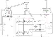
图1为本发明一实施例中一种电池组加热系统的结构示意图。如图1所示,该电池组加热系统包括与电池组P1的正极连接的主正开关K1、与电池组P1的负极连接的主负开关K2、与主正开关K1和主负开关K2连接的逆变器P2、与逆变器P2连接的外接端口G1和G2、与逆变器P2连接的电机P3,以及辅助充电支路控制模块P8、整车控制器P5(Vehicle ControlUnit,VCU)、电机控制器P7(Motor Control Unit,MCU)和电池管理模块P6。电池管理模块P6具体可为电池管理系统(Battery Management System,BMS)。辅助充电支路控制模块P8具体可为电路控制单元(Circuit Control Unit,CCU)。FIG. 1 is a schematic structural diagram of a battery pack heating system according to an embodiment of the present invention. As shown in FIG. 1 , the battery pack heating system includes a main positive switch K1 connected to the positive pole of the battery pack P1, a main negative switch K2 connected to the negative pole of the battery pack P1, and a main positive switch K1 and the main negative switch K2. Inverter P2, external ports G1 and G2 connected to inverter P2, motor P3 connected to inverter P2, auxiliary charging branch control module P8, vehicle controller P5 (Vehicle ControlUnit, VCU), motor Controller P7 (Motor Control Unit, MCU) and battery management module P6. The battery management module P6 may specifically be a battery management system (Battery Management System, BMS). The auxiliary charging branch control module P8 may specifically be a circuit control unit (Circuit Control Unit, CCU).
在一些示例中,还可以在电池组P1与主正开关K1之间设置保险模块,或者,在电池组中多个连接的单体电芯之间设置保险模块,在此并不限定。在一些示例中,保险模块可以为手动维护开关(Manual Service Disconnect,MSD)。In some examples, a fuse module may also be arranged between the battery pack P1 and the main positive switch K1, or a fuse module may be arranged between a plurality of connected single cells in the battery pack, which is not limited herein. In some examples, the safety module may be a manual maintenance switch (Manual Service Disconnect, MSD).
其中,逆变器P2包括多个开关模块。Wherein, the inverter P2 includes a plurality of switch modules.
在一些示例中,如图1所示,逆变器P2包括并联的第一相桥臂、第二相桥臂和第三相桥臂。第一相桥臂、第二相桥臂和第三相桥臂均具有上桥臂和下桥臂。上桥臂设置有开关模块,下桥臂设置有开关模块。即,第一相桥臂为U相桥臂,U相桥臂的上桥臂的开关模块为第一开关模块,U相桥臂的下桥臂的开关模块为第二开关模块。第二相桥臂为V相桥臂,V相桥臂的上桥臂的开关模块为第三开关模块,V相桥臂的下桥臂的开关模块为第四开关模块。第三相桥臂为W相桥臂,W相桥臂的上桥臂的开关模块为第五开关模块,W相桥臂的下桥臂的开关模块为第六开关模块。In some examples, as shown in FIG. 1 , inverter P2 includes a first phase leg, a second phase leg, and a third phase leg in parallel. Each of the first phase bridge arm, the second phase bridge arm and the third phase bridge arm has an upper bridge arm and a lower bridge arm. The upper bridge arm is provided with a switch module, and the lower bridge arm is provided with a switch module. That is, the first phase bridge arm is the U phase bridge arm, the switch module of the upper bridge arm of the U phase bridge arm is the first switch module, and the switch module of the lower bridge arm of the U phase bridge arm is the second switch module. The second-phase bridge arm is the V-phase bridge arm, the switch module of the upper bridge arm of the V-phase bridge arm is the third switch module, and the switch module of the lower bridge arm of the V-phase bridge arm is the fourth switch module. The third-phase bridge arm is the W-phase bridge arm, the switch module of the upper bridge arm of the W-phase bridge arm is the fifth switch module, and the switch module of the lower bridge arm of the W-phase bridge arm is the sixth switch module.
在一些示例中,开关模块可包括绝缘栅双极型晶体管(Insulated Gate BipolarTransistor,IGBT)芯片、IGBT模块、金属-氧化物半导体场效应晶体管(Metal-Oxide-Semiconductor Field-Effect Transistor,MOSFET)等功率开关器件中的一种或多种。在此对开关模块中各IGBT器件和MOSFET器件等的组合方式及连接方式并不限定。对上述功率开关器件的材料类型也不做限定,比如,可采用碳化硅(即SiC)或其他材料制得的功率开关器件。In some examples, the switch module may include an insulated gate bipolar transistor (IGBT) chip, an IGBT module, a metal-oxide-semiconductor field-effect transistor (Metal-Oxide-Semiconductor Field-Effect Transistor, MOSFET) and other power One or more of the switching devices. Here, the combination and connection of each IGBT device, MOSFET device, etc. in the switch module are not limited. The material type of the above-mentioned power switching device is also not limited, for example, a power switching device made of silicon carbide (ie, SiC) or other materials can be used.
具体的,开关模块具有二极管。针对上桥臂的开关模块,二极管的阳极与上桥臂和下桥臂的连接点连接,二极管的阴极位于上桥臂与主正开关K1之间。针对下桥臂的开关模块,二极管的阳极位于下桥臂与主负开关K2之间,二极管的阴极与上桥臂和下桥臂的连接点连接。Specifically, the switch module has a diode. For the switch module of the upper bridge arm, the anode of the diode is connected to the connection point of the upper bridge arm and the lower bridge arm, and the cathode of the diode is located between the upper bridge arm and the main positive switch K1. For the switch module of the lower bridge arm, the anode of the diode is located between the lower bridge arm and the main negative switch K2, and the cathode of the diode is connected to the connection point of the upper bridge arm and the lower bridge arm.
在一些示例中,开关模块包括功率开关器件。上述功率开关器件具有的二极管具体可以为寄生二极管或特意设置的二极管。二极管的材料类型也不做限定,比如,可采用硅(即Si)、碳化硅(即SiC)或其他材料制得的二极管。In some examples, the switch module includes a power switch device. Specifically, the diodes of the above-mentioned power switching devices may be parasitic diodes or specially arranged diodes. The material type of the diode is also not limited, for example, a diode made of silicon (ie, Si), silicon carbide (ie, SiC) or other materials may be used.
逆变器P2与电机P3连接。在一些示例中,如图1所示,电机P3的第一相输入端、第二相输入端和第三相输入端分别与第一相桥臂中上桥臂和下桥臂的连接点、第二相桥臂中上桥臂和下桥臂的连接点和第三相桥臂中上桥臂和下桥臂的连接点连接。The inverter P2 is connected to the motor P3. In some examples, as shown in FIG. 1 , the first-phase input terminal, the second-phase input terminal and the third-phase input terminal of the motor P3 are respectively connected to the connection points of the upper bridge arm and the lower bridge arm of the first phase bridge arm, The connection point of the upper bridge arm and the lower bridge arm in the second phase bridge arm is connected with the connection point of the upper bridge arm and the lower bridge arm in the third phase bridge arm.
比如,如图1所示,将电机P3的定子等效为三相定子电感和电阻。定子电感具有储能功能。每一相定子电感和电阻与一相桥臂连接。将三相定子电感分别作为第一定子电感L1、第二定子电感L2和第三定子电感L3。与第一定子电感L1对应连接的是第一电阻R1,与第二定子电感L2对应连接的是第二电阻R2,与第三定子电感L3对应连接的是第三电阻R3。第一相输入端为第一定子电感L1对应的输入端。第二相输入端为第二定子电感L2对应的输入端。第三相输入端为第三定子电感L3对应的输入端。值得一提的是,电机P3的第一相输入端、第二相输入端和第三相输入端可作为输入端输入电流,也可作为输出端输出电流。For example, as shown in FIG. 1 , the stator of the motor P3 is equivalent to three-phase stator inductance and resistance. The stator inductance has the function of energy storage. Each phase stator inductance and resistance is connected to a phase bridge arm. The three-phase stator inductances are respectively used as the first stator inductance L1, the second stator inductance L2 and the third stator inductance L3. Correspondingly connected to the first stator inductance L1 is a first resistor R1, correspondingly connected to the second stator inductance L2 is a second resistor R2, and correspondingly connected to the third stator inductance L3 is a third resistor R3. The first phase input terminal is the input terminal corresponding to the first stator inductance L1. The input end of the second phase is the input end corresponding to the second stator inductance L2. The input terminal of the third phase is the input terminal corresponding to the third stator inductance L3. It is worth mentioning that the first-phase input terminal, the second-phase input terminal and the third-phase input terminal of the motor P3 can be used as input terminals to input current, and can also be used as output terminals to output current.
具体的,第一定子电感L1的一端即为第一相输入端,第一定子电感L1的另一端与第二定子电感L2的另一端和第三定子电感L3的另一端连接。第二定子电感L2的一端即为第二相输入端。第三定子电感L3的一端即为第三相输入端。Specifically, one end of the first stator inductance L1 is the first phase input end, and the other end of the first stator inductance L1 is connected to the other end of the second stator inductance L2 and the other end of the third stator inductance L3. One end of the second stator inductance L2 is the second phase input end. One end of the third stator inductance L3 is the input end of the third phase.
外接端口G1和G2可连接辅助充电支路P4。该辅助充电支路P4包括供电电源P41。比如,外接端口G1和G2可为高压充电接口。在一些示例中,供电电源P41可以为电压源,该电压源的电压可调。The external ports G1 and G2 can be connected to the auxiliary charging branch P4. The auxiliary charging branch P4 includes a power supply P41. For example, the external ports G1 and G2 may be high-voltage charging ports. In some examples, the power supply P41 may be a voltage source whose voltage is adjustable.
电池管理模块P6用于获取电池组P1的状态参数,若电池组P1的状态参数满足预设低温低电量条件,向整车控制器P5和辅助充电支路控制模块P8分别发送低温低电量加热请求指令。若电池组P1的状态参数满足预设低温低电量条件,表示电池组P1的状态参数不足以支持电池组P1的正常工作。低温低电量加热请求指令用于指示请求电池组加热系统进入低温低电量加热模式。The battery management module P6 is used to obtain the state parameters of the battery pack P1. If the state parameters of the battery pack P1 meet the preset low temperature and low battery conditions, it sends a low temperature and low battery heating request to the vehicle controller P5 and the auxiliary charging branch control module P8 respectively. instruction. If the state parameter of the battery pack P1 satisfies the preset low temperature and low battery condition, it means that the state parameter of the battery pack P1 is insufficient to support the normal operation of the battery pack P1. The low temperature and low power heating request command is used to instruct the battery pack heating system to enter the low temperature and low power heating mode.
在一些示例中,状态参数包括温度和荷电状态。预设低温低电量条件包括温度低于加热温度阈值,且荷电状态低于加热荷电状态要求阈值。若状态参数满足预设低温低电量条件,表示电池组P1的温度不足以支持电池组P1正常工作,且电池组P1的荷电状态不足以支持对电池组P1的加热。In some examples, the state parameters include temperature and state of charge. The preset low temperature and low battery conditions include that the temperature is lower than the heating temperature threshold, and the state of charge is lower than the heating state of charge requirement threshold. If the state parameter satisfies the preset low temperature and low battery condition, it means that the temperature of the battery pack P1 is not enough to support the normal operation of the battery pack P1, and the state of charge of the battery pack P1 is not sufficient to support the heating of the battery pack P1.
这里的电池组P1的温度具体可为电池组P1壳体的温度,也可为电池组P1内部空间中空气的温度,也可为电池组P1中任意一个电池组P1或电池单元的温度,还可为电池组P1中所有电池单元的温度的平均值等等,在此并不限定。The temperature of the battery pack P1 here may specifically be the temperature of the casing of the battery pack P1, the temperature of the air in the interior space of the battery pack P1, or the temperature of any battery pack P1 or battery cell in the battery pack P1, or the temperature of the battery pack P1. It can be the average value of the temperature of all the battery cells in the battery pack P1, etc., which is not limited here.
加热温度阈值可为电池组P1可正常工作的最低要求温度,即电池组加热系统需要被加热的温度的门限。加热温度阈值可根据工作场景和工作需求设定,在此并不限定。比如,加热温度阈值可为阈值范围[-50℃,5℃]中的任一取值。若电池组P1的温度低于加热温度阈值,则电池组P1无法正常工作,需要进行加热。The heating temperature threshold may be the minimum required temperature at which the battery pack P1 can work normally, that is, the threshold of the temperature at which the battery pack heating system needs to be heated. The heating temperature threshold can be set according to the work scenario and work requirements, and is not limited here. For example, the heating temperature threshold can be any value in the threshold range [-50°C, 5°C]. If the temperature of the battery pack P1 is lower than the heating temperature threshold, the battery pack P1 cannot work normally and needs to be heated.
加热荷电状态要求阈值可为对电池组P1进行本次加热所需要消耗的荷电状态,即电池组加热系统对电池组P1进行加热所需的荷电状态的门限。加热荷电状态要求阈值可根据工作场景和工作需求预先设定,也可由电池管理模块P6根据电池组P1的当前温度进行估算得到,在此并不限定。比如,加热荷电状态要求阈值可为阈值范围[5%,100%)中的任一取值。若电池组P1的温度低于加热温度阈值,且电池组P1的荷电状态低于加热荷电状态要求阈值,需要辅助充电支路P4的供电电源P41提供用于加热电池组P1的至少部分能量。The required threshold for the heating state of charge may be the state of charge required to heat the battery pack P1 this time, that is, the threshold of the state of charge required by the battery pack heating system to heat the battery pack P1. The required threshold value of the heating state of charge may be preset according to the working scenario and working requirements, or may be estimated by the battery management module P6 according to the current temperature of the battery pack P1, which is not limited herein. For example, the heating state of charge requirement threshold may be any value in the threshold range [5%, 100%). If the temperature of the battery pack P1 is lower than the heating temperature threshold, and the state of charge of the battery pack P1 is lower than the heating state of charge requirement threshold, the power supply P41 of the auxiliary charging branch P4 is required to provide at least part of the energy for heating the battery pack P1 .
辅助充电支路控制模块P8用于响应低温低电量加热请求指令,向辅助充电支路P4发送第一控制信号,以控制电池组加热系统与辅助充电支路P4导通,使得供电电源P41通过外接端口G1和G2向电池组P1和/或电机P3传输能量。The auxiliary charging branch control module P8 is used to respond to the low temperature and low battery heating request instruction, and send the first control signal to the auxiliary charging branch P4 to control the conduction between the battery pack heating system and the auxiliary charging branch P4, so that the power supply P41 is connected through an external Ports G1 and G2 transmit energy to battery pack P1 and/or motor P3.
整车控制器P5用于向电机控制器P7发送第二控制信号,使电机控制器P7控制逆变器P2中的开关模块的通断。The vehicle controller P5 is used for sending a second control signal to the motor controller P7, so that the motor controller P7 controls the on-off of the switch module in the inverter P2.
整车控制器P5还用于向电池管理模块P6发送第三控制信号,使电池管理模块P6控制主正开关K1的通断。The vehicle controller P5 is further configured to send a third control signal to the battery management module P6, so that the battery management module P6 controls the on-off of the main positive switch K1.
整车控制器P5发送第二控制信号、第三控制信号,一方面可与辅助充电支路控制模块P8发送的第一控制信号相配合,使辅助充电支路P4的供电电源P41通过外接端口G1和G2向电池组P1和/或电机P3传输能量。即,使电池组P1接收辅助充电支路P4的供电电源P41传输来的能量,和/或使电机P3接收辅助充电支路P4的供电电源P41传输来的能量。另一方面,第二控制信号和第三控制信号相配合,使电池组P1与电机P3之间相互传递能量,以对电池组P1进行加热。即,使能量由电池组P1传输至电机P3,由电机P3再传输回电池组P1,循环多次,形成电池组P1充、放电的多次循环,从而在电池组P1所在的回路中产生交流电流。The vehicle controller P5 sends the second control signal and the third control signal. On the one hand, it can cooperate with the first control signal sent by the auxiliary charging branch control module P8, so that the power supply P41 of the auxiliary charging branch P4 can pass through the external port G1. And G2 transmits energy to battery pack P1 and/or motor P3. That is, the battery pack P1 is made to receive energy from the power supply P41 of the auxiliary charging branch P4, and/or the motor P3 is made to receive energy from the power supply P41 of the auxiliary charging branch P4. On the other hand, the coordination of the second control signal and the third control signal enables the battery pack P1 and the motor P3 to transfer energy to each other, so as to heat the battery pack P1. That is, the energy is transmitted from the battery pack P1 to the motor P3, and then transferred back to the battery pack P1 by the motor P3, and the cycle is repeated for many times to form multiple cycles of charging and discharging of the battery pack P1, thereby generating an alternating current in the circuit where the battery pack P1 is located. current.
在一些示例中,整车控制器P5响应低温低电量加热请求指令,还可控制车载仪器仪表发出用于提示用户选择是否允许低温低电量加热请求指令的提示消息。若接收到表征允许低温低电量加热请求指令的输入操作,在后续的过程中,辅助充电支路控制模块P8再发送第一控制信号,整车控制器P5再发送第二控制信号和第三控制信号等。In some examples, in response to the low temperature and low battery heating request command, the vehicle controller P5 may also control the on-board instrumentation to issue a prompt message for prompting the user to select whether to allow the low temperature and low battery heating request command. If the input operation representing the request command for allowing low temperature and low battery heating is received, in the subsequent process, the auxiliary charging branch control module P8 sends the first control signal again, and the vehicle controller P5 sends the second control signal and the third control signal again. signal etc.
需要说明的是,在电池管理模块P6获取电池组P1的状态参数,判断电池组P1的状态参数满足预设低温低电量条件之前,还可先进行整车的上电自检。若整车的上电自检正常,再进行电池管理模块P6的电池组P1的状态参数与预设低温低电量条件的判断。具体的,用户通过钥匙打开汽车的Key_On档,整车控制器P5会接收到触发上电信号,从而触发上电。整车控制器P5进行自检是否正常,若不正常,则上报整车故障信息。电池管理模块P6也可进行检测,检测电池管理模块P6以及电池组P1是否发生故障,若发生故障,向整车控制器P5发送电池管理故障信息。并不进行电池管理模块P6的电池组P1的状态参数与预设低温低电量条件的判断。整车控制器P5接收电池管理故障信息,并上报。同理,电机控制器P7也可进行检测,若电机控制器P7检测到车辆此时正处于行驶状态,则向整车控制器P5发送通知消息,整车控制器P5控制电池管理模块P6不进行电池组P1的状态参数与预设低温低电量条件的判断。即当电池管理模块P6、电池组P1、整车控制器P5、电机控制器P7和电机P3均处于正常状态,才进行电池管理模块P6的电池组P1的状态参数与预设低温低电量条件的判断以及后续的操作。It should be noted that, before the battery management module P6 obtains the state parameters of the battery pack P1 and determines that the state parameters of the battery pack P1 meet the preset low temperature and low battery conditions, a power-on self-check of the entire vehicle may be performed first. If the power-on self-check of the whole vehicle is normal, then the state parameters of the battery pack P1 of the battery management module P6 and the preset low temperature and low battery conditions are judged. Specifically, when the user turns on the Key_On gear of the car through the key, the vehicle controller P5 will receive the power-on triggering signal, thereby triggering the power-on. The vehicle controller P5 checks whether it is normal. If it is not normal, it reports the vehicle fault information. The battery management module P6 can also perform detection to detect whether the battery management module P6 and the battery pack P1 are faulty, and if a fault occurs, the battery management fault information is sent to the vehicle controller P5. The judgment of the state parameters of the battery pack P1 of the battery management module P6 and the preset low temperature and low battery condition is not performed. The vehicle controller P5 receives the battery management fault information and reports it. In the same way, the motor controller P7 can also perform detection. If the motor controller P7 detects that the vehicle is in a driving state at this time, it will send a notification message to the vehicle controller P5, and the vehicle controller P5 controls the battery management module P6 not to perform the detection. Judgment of the state parameters of the battery pack P1 and the preset low temperature and low battery conditions. That is, when the battery management module P6, the battery pack P1, the vehicle controller P5, the motor controller P7 and the motor P3 are all in the normal state, the state parameters of the battery pack P1 of the battery management module P6 and the preset low temperature and low battery conditions are compared. judgment and subsequent actions.
在本发明实施例中,电池管理模块P6确定电池组P1的状态参数满足预设低温低电量条件,向整车控制器P5和辅助充电支路控制模块P8分别发送低温低电量加热请求指令,以请求进行低温低电量加热模式。电池管理模块P6通过控制辅助充电支路控制模块P8,整车控制器P5通过控制电池管理模块P6和电机控制器P7,控制辅助充电支路P4、主正开关K1和逆变器P2中的开关模块,使辅助充电支路P4中供电电源P41向电池和/或电机P3传输能量,以使电池组P1和电机P3具有充足的可支持对电池组P1加热的能量。电池组P1与电机P3之间相互传递能量,形成电池组P1充、放电的循环,在电池组P1所在的回路中产生电流。交流电流可连续不断的通过电池组P1,使得电池组P1的内阻发热,从而在低电量的情况下也可实现对电池组P1的均匀、高效率的自加热。In the embodiment of the present invention, the battery management module P6 determines that the state parameters of the battery pack P1 meet the preset low temperature and low battery conditions, and sends the low temperature and low battery heating request commands to the vehicle controller P5 and the auxiliary charging branch control module P8 respectively, so as to Request low temperature low battery heating mode. The battery management module P6 controls the auxiliary charging branch control module P8, and the vehicle controller P5 controls the auxiliary charging branch P4, the main positive switch K1 and the switches in the inverter P2 by controlling the battery management module P6 and the motor controller P7. The module enables the power supply P41 in the auxiliary charging branch P4 to transmit energy to the battery and/or the motor P3, so that the battery pack P1 and the motor P3 have sufficient energy to support the heating of the battery pack P1. The battery pack P1 and the motor P3 transfer energy to each other to form a charge and discharge cycle of the battery pack P1, and a current is generated in the circuit where the battery pack P1 is located. The alternating current can pass through the battery pack P1 continuously, so that the internal resistance of the battery pack P1 generates heat, so that even and high-efficiency self-heating of the battery pack P1 can be achieved even in the case of low power.
图2为本发明另一实施例中一种电池组加热系统的结构示意图。如图2所示,电池组加热系统还包括支撑电容C1、预充支路P9和辅助充电支路P4。上述辅助充电支路P4还可包括辅助开关模块。FIG. 2 is a schematic structural diagram of a battery pack heating system in another embodiment of the present invention. As shown in FIG. 2 , the battery pack heating system further includes a support capacitor C1 , a precharging branch P9 and an auxiliary charging branch P4 . The above-mentioned auxiliary charging branch P4 may further include an auxiliary switch module.
为了便于说明,在本发明实施例中,以图2所示的各个器件为例进行说明。第一开关模块包括第一功率开关器件S1,第二开关模块包括第二功率开关器件S2,第三开关模块包括第三功率开关器件S3,第四开关模块包括第四功率开关器件S4,第五开关模块包括第五功率开关器件S5,第六开关模块包括第六功率开关器件S6。其中,第一功率开关器件S1的二极管为VD1,第二功率开关器件S2的二极管为VD2,第三功率开关器件S3的二极管为VD3,第四功率开关器件S4的二极管为VD4,第五功率开关器件S5的二极管为VD5,第六功率开关器件S6的二极管为VD6。For convenience of description, in this embodiment of the present invention, each device shown in FIG. 2 is used as an example for description. The first switch module includes a first power switch device S1, the second switch module includes a second power switch device S2, the third switch module includes a third power switch device S3, the fourth switch module includes a fourth power switch device S4, and the fifth switch module includes a fourth power switch device S4. The switch module includes a fifth power switch device S5, and the sixth switch module includes a sixth power switch device S6. The diode of the first power switch device S1 is VD1, the diode of the second power switch device S2 is VD2, the diode of the third power switch device S3 is VD3, the diode of the fourth power switch device S4 is VD4, and the fifth power switch The diode of the device S5 is VD5, and the diode of the sixth power switching device S6 is VD6.
辅助充电支路控制模块P8用于响应低温低电量加热请求指令,向辅助开关模块发送第一控制信号,以控制辅助开关模块导通。即辅助开关模块响应第一控制信号而导通。辅助充电支路P4中的辅助开关模块具体可为开关器件K3。则开关器件K3可响应于第一控制信号导通。The auxiliary charging branch control module P8 is used to respond to the low temperature and low battery heating request instruction, and send a first control signal to the auxiliary switch module to control the auxiliary switch module to be turned on. That is, the auxiliary switch module is turned on in response to the first control signal. The auxiliary switch module in the auxiliary charging branch P4 may specifically be a switch device K3. Then the switching device K3 can be turned on in response to the first control signal.
预充支路P9与主正开关K1并联。预充支路P9可包括预充开关K4和预充电阻。The pre-charging branch P9 is connected in parallel with the main positive switch K1. The precharge branch P9 may include a precharge switch K4 and a precharge resistor.
电池管理模块P6还用于向预充开关K4发送第三驱动信号,以控制预充开关K4导通,进行预充电。需要说明的是,预充开关K4导通,主正开关K1断开,主负开关K2导通,电池组P1、预充支路P9、支撑电容C1、主负开关K2形成回路,从而实现预充电。The battery management module P6 is further configured to send a third driving signal to the precharge switch K4, so as to control the precharge switch K4 to be turned on to perform precharge. It should be noted that, the precharge switch K4 is turned on, the main positive switch K1 is turned off, the main negative switch K2 is turned on, the battery pack P1, the precharge branch P9, the support capacitor C1, and the main negative switch K2 form a loop, thereby realizing the pre-charging operation. Charge.
电池管理模块P6若检测到预充电完成,停止向预充开关K4发送第三驱动信号,以控制预充开关K4断开,结束预充电。If the battery management module P6 detects that the pre-charging is completed, it stops sending the third driving signal to the pre-charging switch K4, so as to control the pre-charging switch K4 to be turned off and end the pre-charging.
下面介绍进入低温低电量加热模式,电池组加热系统中各个部分的功能和具体运行。The following introduces the function and specific operation of each part of the battery pack heating system when entering the low temperature and low power heating mode.
具体的,电机控制器P7可具体用于响应第二控制信号,向逆变器P2中的部分开关模块发送第一驱动信号,以驱动部分开关模块周期性导通和断开,使电机P3接收供电电源P41传输来的能量,或使电机P3接收电池组P1传输来的能量,或使电机控制器P7向电池组P1传输能量。Specifically, the motor controller P7 may be specifically configured to respond to the second control signal and send the first drive signal to some of the switch modules in the inverter P2, so as to drive some of the switch modules to be turned on and off periodically, so that the motor P3 receives The energy transmitted from the power supply P41 either enables the motor P3 to receive the energy transmitted from the battery pack P1, or enables the motor controller P7 to transmit energy to the battery pack P1.
其中,响应第一驱动信号被导通的开关模块包括目标上桥臂开关模块和目标下桥臂开关模块,目标上桥臂开关模块为第一相桥臂、第二相桥臂、第三相桥臂中任意一个桥臂的上桥臂的开关模块,目标下桥臂开关模块为除目标上桥臂开关模块所在的桥臂外的至少一个桥臂的下桥臂的开关模块。具体的,开关模块导通,则开关模块中的功率开关器件导通。开关模块断开,则开关模块中的功率开关器件断开。Wherein, the switch module that is turned on in response to the first drive signal includes a target upper bridge arm switch module and a target lower bridge arm switch module, and the target upper bridge arm switch module is a first-phase bridge arm, a second-phase bridge arm, a third-phase bridge arm The switch module of the upper bridge arm of any bridge arm, and the target lower bridge arm switch module is the switch module of the lower bridge arm of at least one bridge arm except the bridge arm where the target upper bridge arm switch module is located. Specifically, when the switch module is turned on, the power switch device in the switch module is turned on. When the switch module is disconnected, the power switching device in the switch module is disconnected.
需要说明的是,没有收到第一驱动信号驱动的开关模块均断开。即除目标上桥臂开关模块和目标下桥臂开关模块之外的开关模块均断开。It should be noted that the switch modules that are not driven by the first driving signal are all disconnected. That is, the switch modules except the target upper bridge arm switch module and the target lower arm switch module are all disconnected.
比如,如图2所示,若目标上桥臂开关模块为第一开关模块,则目标下桥臂开关模块为第四开关模块和/或第六开关模块。若目标上桥臂开关模块为第三开关模块,则目标下桥臂开关模块为第二开关模块和/或第六开关模块。若目标上桥臂开关模块为第五开关模块,则目标下桥臂开关模块为第二开关模块和/或第四开关模块。For example, as shown in FIG. 2 , if the target upper arm switch module is the first switch module, the target lower arm switch module is the fourth switch module and/or the sixth switch module. If the target upper arm switch module is the third switch module, the target lower arm switch module is the second switch module and/or the sixth switch module. If the target upper arm switch module is the fifth switch module, the target lower arm switch module is the second switch module and/or the fourth switch module.
电池管理模块P6还用于响应第三控制信号,向主正开关K1发送第二驱动信号,以驱动主正开关K1周期性导通和断开,使电池组P1接收供电电源P41传输来的能量,或使电池组P1接收电机P3传输来的能量,或使电池组P1向电机P3传输能量。The battery management module P6 is also used to respond to the third control signal and send a second driving signal to the main positive switch K1 to drive the main positive switch K1 to periodically turn on and off, so that the battery pack P1 receives the energy transmitted from the power supply P41 , or enable the battery pack P1 to receive the energy transmitted by the motor P3, or enable the battery pack P1 to transmit energy to the motor P3.
在一些实施例中,电池管理模块P6向辅助充电支路控制模块P8发送低温低电量加热请求指令。整车控制器P5向电池管理模块P6发送第三控制信号。In some embodiments, the battery management module P6 sends a low temperature and low battery heating request command to the auxiliary charging branch control module P8. The vehicle controller P5 sends a third control signal to the battery management module P6.
需要说明的是,供电电源P41的电压高于电池组P1的当前电压。入辅助充电支路控制模块P8响应低温低电量加热请求,可向辅助开关模块发送第一控制信号。辅助开关模块响应第一控制信号而导通。It should be noted that the voltage of the power supply P41 is higher than the current voltage of the battery pack P1. The input auxiliary charging branch control module P8 can send a first control signal to the auxiliary switch module in response to the low temperature and low battery heating request. The auxiliary switch module is turned on in response to the first control signal.
电池管理模块P6响应第三控制信号,向主正开关K1发送第二驱动信号。主正开关K1响应第二驱动信号周期性导通和断开。在主正开关K1周期性导通和断开的过程中,辅助充电支路P4的供电电源P41的能量可通过开关器件K3传递给电池组P1,相当于对电池组P1充电。值得一提的是,辅助充电支路P4的供电电源P41通过开关器件K3、外接端口G1和G2向电池组P1传输能量可通过一次或多次完成,在此并不限定。目的是使电池组P1的能量能够支持对电池组P1进行自加热。The battery management module P6 sends a second driving signal to the main positive switch K1 in response to the third control signal. The main positive switch K1 is periodically turned on and off in response to the second driving signal. When the main positive switch K1 is periodically turned on and off, the energy of the power supply P41 of the auxiliary charging branch P4 can be transferred to the battery pack P1 through the switch device K3, which is equivalent to charging the battery pack P1. It is worth mentioning that the power supply P41 of the auxiliary charging branch P4 transmits energy to the battery pack P1 through the switching device K3 and the external ports G1 and G2 in one or more times, which is not limited here. The purpose is to enable the energy of the battery pack P1 to support the self-heating of the battery pack P1.
电池管理模块P6向辅助充电支路控制模块P8发送指示控制辅助充电支路P4中辅助开关模块断开的信号。辅助充电支路控制模块P8响应该信号,向辅助开关模块发送指示控制辅助开关模块断开的信号,辅助开关模块断开。整车控制器P5向电机控制器P7发送第二控制信号。电机控制器P7响应第二控制信号,向逆变器P2中的部分开关模块发送第一驱动信号。逆变器P2中的目标上桥臂开关模块和目标下桥臂开关模块响应第一驱动信号周期性导通和断开。The battery management module P6 sends to the auxiliary charging branch control module P8 a signal indicating to control the disconnection of the auxiliary switch module in the auxiliary charging branch P4. In response to the signal, the auxiliary charging branch control module P8 sends to the auxiliary switch module a signal indicating to control the disconnection of the auxiliary switch module, and the auxiliary switch module is disconnected. The vehicle controller P5 sends a second control signal to the motor controller P7. In response to the second control signal, the motor controller P7 sends a first driving signal to part of the switch modules in the inverter P2. The target upper arm switch module and the target lower arm switch module in the inverter P2 are periodically turned on and off in response to the first drive signal.
比如,目标上桥臂开关模块为第一开关模块,目标下桥臂开关模块为第四开关模块。响应第一驱动信号,第一开关模块和第五开关模块可周期性导通和断开。具体的,第一功率开关器件S1和第五功率开关器件S5导通,相当于电池组P1放电,电流方向为:电池组P1→主正开关K1→第一功率开关器件S1→第一定子电感L1→第一电阻R1→第二电阻R2→第二定子电感L2→第五功率开关器件S5→主负开关K2→电池组P1。第一功率开关器件S1和第五功率开关器件S5断开,相当于电池组P1充电,电流方向为:第一定子电感L1→第一电阻R1→第二电阻R2→第二定子电感L2→第二功率开关器件S2的二极管VD2→主正开关K1→电池组P1→主负开关K2→第四功率开关器件S4的二极管VD4→第一定子电感L1。For example, the target upper bridge arm switch module is the first switch module, and the target lower bridge arm switch module is the fourth switch module. In response to the first driving signal, the first switch module and the fifth switch module may be periodically turned on and off. Specifically, the first power switch device S1 and the fifth power switch device S5 are turned on, which is equivalent to the discharge of the battery pack P1, and the current direction is: the battery pack P1 → the main positive switch K1 → the first power switch device S1 → the first stator Inductance L1→first resistance R1→second resistance R2→second stator inductance L2→fifth power switching device S5→main negative switch K2→battery pack P1. The first power switching device S1 and the fifth power switching device S5 are disconnected, which is equivalent to charging the battery pack P1, and the current direction is: the first stator inductance L1 → the first resistance R1 → the second resistance R2 → the second stator inductance L2 → The diode VD2 of the second power switching device S2→the main positive switch K1→the battery pack P1→the main negative switch K2→the diode VD4 of the fourth power switching device S4→the first stator inductance L1.
目标上桥臂开关模块和目标下桥臂开关模块的选取并不限于上述示例,且目标上桥臂开关模块和目标下桥臂开关模块的选取不同,形成的电池组P1的放电回路和充电回路也不同,在此并不限定。The selection of the target upper bridge arm switch module and the target lower bridge arm switch module is not limited to the above example, and the selection of the target upper bridge arm switch module and the target lower arm switch module is different, forming the discharge loop and the charging loop of the battery pack P1. Also different, it is not limited here.
需要说明的是,在一些示例中,主正开关K1与目标上桥臂开关模块和目标下桥臂开关模块不同时导通,可通过支撑电容C1将电池组P1的能量传输给电机P3,实现电池组P1的充电和放电。It should be noted that, in some examples, the main positive switch K1 and the target upper arm switch module and the target lower arm switch module are not turned on at the same time, and the energy of the battery pack P1 can be transmitted to the motor P3 through the support capacitor C1 to achieve Charging and discharging of battery pack P1.
在第二驱动信号驱动主正开关K1导通的情况下,第一驱动信号驱动部分开关模块(即目标上桥臂开关模块和目标下桥臂开关模块)断开。若电机P3中存储的能量低于电池组P1存储的能量,则电池组P1向支撑电容C1传输能量。若电机P3中存储的能量高于电池组P1存储的能量,则电池组P1接收电机P3传输来的能量。When the second drive signal drives the main positive switch K1 to be turned on, the first drive signal drives some of the switch modules (ie, the target upper arm switch module and the target lower arm switch module) to turn off. If the energy stored in the motor P3 is lower than the energy stored in the battery pack P1, the battery pack P1 transmits energy to the support capacitor C1. If the energy stored in the motor P3 is higher than the energy stored in the battery pack P1, the battery pack P1 receives the energy transmitted from the motor P3.
在第一驱动信号驱动部分开关模块(即目标上桥臂开关模块和目标下桥臂开关模块)导通的情况下,第二驱动信号驱动主正开关K1断开。电机P3接收支撑电容C1传输来的能量,支撑电容C1的能量是从电池组P1得来的。When the first driving signal drives some of the switch modules (ie, the target upper arm switch module and the target lower arm switch module) to be turned on, the second drive signal drives the main positive switch K1 to turn off. The motor P3 receives the energy transmitted by the support capacitor C1, and the energy of the support capacitor C1 is obtained from the battery pack P1.
反复重复上述电池组P1放电和充电的过程,以实现对电池组P1的自加热。The above process of discharging and charging the battery pack P1 is repeated repeatedly to achieve self-heating of the battery pack P1.
在另一个实施例中,电池管理模块P6向辅助充电支路控制模块P8发送低温低电量加热请求指令,整车控制器P5向电机控制器P7发送第二控制信号。In another embodiment, the battery management module P6 sends a low temperature and low battery heating request command to the auxiliary charging branch control module P8, and the vehicle controller P5 sends a second control signal to the motor controller P7.
供电电源P41的电压高于电池组P1的当前电压。辅助充电支路控制模块P8响应低温低电量加热请求指令,向辅助开关模块发送第一控制信号。辅助开关模块响应第一控制信号而导通。The voltage of the power supply P41 is higher than the current voltage of the battery pack P1. The auxiliary charging branch control module P8 sends a first control signal to the auxiliary switch module in response to the low temperature and low battery heating request instruction. The auxiliary switch module is turned on in response to the first control signal.
电机控制器P7响应第二控制信号,向逆变器P2中的部分开关模块发送第一驱动信号。逆变器P2中的目标上桥臂开关模块和目标下桥臂开关模块响应第一驱动信号周期性导通和断开。逆变器P2中的目标上桥臂开关模块和目标下桥臂开关模块导通的过程中,辅助充电支路P4的供电电源P41的能量可通过开关器件K3传递给电机P3,相当于对电机P3进行充电。值得一提的是,辅助充电支路P4的供电电源P41通过开关器件K3、外接端口G1和G2向电机P3传递能量可通过一次或多次完成,在此并不限定。目的是使电池组P1的能量和电机P3的能量能够支持对电池组P1进行自加热。In response to the second control signal, the motor controller P7 sends a first driving signal to part of the switch modules in the inverter P2. The target upper arm switch module and the target lower arm switch module in the inverter P2 are periodically turned on and off in response to the first drive signal. During the conduction process of the target upper bridge arm switch module and the target lower bridge arm switch module in the inverter P2, the energy of the power supply P41 of the auxiliary charging branch P4 can be transmitted to the motor P3 through the switch device K3, which is equivalent to the electric motor P3. P3 to charge. It is worth mentioning that the power supply P41 of the auxiliary charging branch P4 transmits energy to the motor P3 through the switching device K3 and the external ports G1 and G2 in one or more times, which is not limited here. The purpose is to enable the energy of the battery P1 and the energy of the motor P3 to support the self-heating of the battery P1.
电池管理模块P6向辅助充电支路控制模块P8发送指示控制辅助充电支路P4中辅助开关模块断开的信号。辅助充电支路控制模块P8响应该信号,向辅助开关模块发送指示控制辅助开关模块断开的信号,辅助开关模块断开。整车控制器P5向电池管理模块P6发送第三控制信号。电池管理模块P6响应第三控制信号,向主正开关K1发送第二驱动信号。主正开关K1响应第二驱动信号周期性导通和断开。The battery management module P6 sends to the auxiliary charging branch control module P8 a signal indicating to control the disconnection of the auxiliary switch module in the auxiliary charging branch P4. In response to the signal, the auxiliary charging branch control module P8 sends to the auxiliary switch module a signal indicating to control the disconnection of the auxiliary switch module, and the auxiliary switch module is disconnected. The vehicle controller P5 sends a third control signal to the battery management module P6. The battery management module P6 sends a second driving signal to the main positive switch K1 in response to the third control signal. The main positive switch K1 is periodically turned on and off in response to the second driving signal.
在主正开关K1周期性导通和断开,逆变器P2中的目标上桥臂开关模块和目标下桥臂开关模块周期性导通和断开,可通过支撑电容C1将电池组P1的能量传输至电机P3,电机P3可将能量传输至电池组P1。电池组P1与电机P3之间的能量的相互传输可参见上述实施例,在此不再赘述。When the main positive switch K1 is periodically turned on and off, the target upper bridge arm switch module and the target lower bridge arm switch module in the inverter P2 are periodically turned on and off, and the battery pack P1 can be connected to the battery pack P1 through the supporting capacitor C1. The energy is transmitted to the motor P3, which can transmit energy to the battery pack P1. For the mutual transmission of energy between the battery pack P1 and the motor P3, reference may be made to the above embodiments, and details are not described herein again.
在又一个实施例中,电池管理模块P6向辅助充电支路控制模块P8发送低温低电量加热请求指令。整车控制器P5向电机控制器P7发送第二控制信号,向电池管理模块P6发送第三控制信号。In yet another embodiment, the battery management module P6 sends a low temperature and low battery heating request instruction to the auxiliary charging branch control module P8. The vehicle controller P5 sends the second control signal to the motor controller P7, and sends the third control signal to the battery management module P6.
供电电源P41的电压高于电池组P1的当前电压。辅助充电支路控制模块P8响应低温低电量加热请求指令,向辅助开关模块发送第一控制信号。辅助开关模块响应第一控制信号而导通。The voltage of the power supply P41 is higher than the current voltage of the battery pack P1. The auxiliary charging branch control module P8 sends a first control signal to the auxiliary switch module in response to the low temperature and low battery heating request instruction. The auxiliary switch module is turned on in response to the first control signal.
电机控制器P7响应第二控制信号,向逆变器P2中的部分开关模块发送第一驱动信号。逆变器P2中的目标上桥臂开关模块和目标下桥臂开关模块响应第一驱动信号周期性导通和断开。逆变器P2中的目标上桥臂开关模块和目标下桥臂开关模块导通的过程中,辅助充电支路P4的供电电源P41的能量可通过开关器件K3、外接端口G1和G2传递给电机P3,相当于对电机P3进行充电。In response to the second control signal, the motor controller P7 sends a first driving signal to part of the switch modules in the inverter P2. The target upper arm switch module and the target lower arm switch module in the inverter P2 are periodically turned on and off in response to the first drive signal. When the target upper bridge arm switch module and the target lower bridge arm switch module in the inverter P2 are turned on, the energy of the power supply P41 of the auxiliary charging branch P4 can be transferred to the motor through the switch device K3 and the external ports G1 and G2 P3 is equivalent to charging the motor P3.
电池管理模块P6响应第三控制信号,向主正开关K1发送第二驱动信号。主正开关K1响应第二驱动信号周期性导通和断开。在主正开关K1周期性导通和断开的过程中,辅助充电支路P4的供电电源P41的能量可通过开关器件K3、外接端口G1和G2传递给电池组P1,相当于对电池组P1充电。The battery management module P6 sends a second driving signal to the main positive switch K1 in response to the third control signal. The main positive switch K1 is periodically turned on and off in response to the second driving signal. During the period when the main positive switch K1 is periodically turned on and off, the energy of the power supply P41 of the auxiliary charging branch P4 can be transferred to the battery pack P1 through the switch device K3 and the external ports G1 and G2, which is equivalent to the battery pack P1 Charge.
值得一提的是,辅助充电支路P4的供电电源P41通过开关器件K3、外接端口G1和G2向电池组P1和电机P3传输能量可通过一次或多次完成,在此并不限定目的是使电池组P1的能量和电机P3的能量能够支持对电池组P1进行自加热。It is worth mentioning that the power supply P41 of the auxiliary charging branch P4 transmits energy to the battery pack P1 and the motor P3 through the switching device K3 and the external ports G1 and G2 in one or more times. The energy of the battery P1 and the energy of the motor P3 can support the self-heating of the battery P1.
电池管理模块P6向辅助充电支路控制模块P8发送指示控制辅助充电支路P4中辅助开关模块断开的信号。辅助充电支路控制模块P8响应该信号,向辅助开关模块发送指示控制辅助开关模块断开的信号,辅助开关模块断开。The battery management module P6 sends to the auxiliary charging branch control module P8 a signal indicating to control the disconnection of the auxiliary switch module in the auxiliary charging branch P4. In response to the signal, the auxiliary charging branch control module P8 sends to the auxiliary switch module a signal indicating to control the disconnection of the auxiliary switch module, and the auxiliary switch module is disconnected.
逆变器P2中的目标上桥臂开关模块和目标下桥臂开关模块响应第一驱动信号周期性导通和断开。主正开关K1响应第二驱动信号周期性导通和断开。可通过支撑电容C1将电池组P1的能量传输至电机P3,电机P3可将能量传输至电池组P1。电池组P1与电机P3之间的能量的相互传输可参见上述实施例,在此不再赘述。The target upper arm switch module and the target lower arm switch module in the inverter P2 are periodically turned on and off in response to the first drive signal. The main positive switch K1 is periodically turned on and off in response to the second driving signal. The energy of the battery pack P1 can be transmitted to the electric motor P3 through the supporting capacitor C1, and the electric motor P3 can transmit the energy to the battery pack P1. For the mutual transmission of energy between the battery pack P1 and the motor P3, reference may be made to the above embodiments, and details are not described herein again.
需要说明的是,整车控制器P5、辅助充电支路控制模块P8、电池管理模块P6和电机控制器P7的相互配合,控制辅助开关模块、逆变器P2中的开关模块和主正开关K1的通断,以实现对电池组P1的自加热包括但并不限于上述实施例的方式。It should be noted that the vehicle controller P5, the auxiliary charging branch control module P8, the battery management module P6 and the motor controller P7 cooperate with each other to control the auxiliary switch module, the switch module in the inverter P2 and the main positive switch K1. The on-off of the battery pack P1 to realize the self-heating of the battery pack P1 includes but is not limited to the methods of the above-mentioned embodiments.
在一些示例中,电池管理模块P6还用于将获取的电池组P1的状态参数向整车控制器P5发送。其中,电池组P1的状态参数包括荷电状态和温度。In some examples, the battery management module P6 is further configured to send the acquired state parameters of the battery pack P1 to the vehicle controller P5. The state parameters of the battery pack P1 include state of charge and temperature.
整车控制器P5还用于将接收到的电池组P10的状态参数向电机控制器P7发送。The vehicle controller P5 is also used to send the received state parameters of the battery pack P10 to the motor controller P7.
电机控制器P7还用于基于期望温升速率和接收到的电池组P1的状态参数,计算得到第一期望频率和第一期望占空比,并将第一驱动信号的频率和占空比调节为第一期望频率和第一期望占空比。The motor controller P7 is also used to calculate the first expected frequency and the first expected duty cycle based on the expected temperature rise rate and the received state parameters of the battery pack P1, and adjust the frequency and duty cycle of the first drive signal is the first desired frequency and the first desired duty cycle.
电机控制器P7可根据电池组P1的温度,得到电池组P1的温升速率。期望温升速率为预期的温升速率,可根据具体工作场景和工作需求设定,在此并不限定。将第一驱动信号的频率和占空比调节为第一期望频率和第一期望占空比,可调整对电池组P1的加热速率。计算第一期望频率和第一期望占空比的过程可实时进行,并实时调节第一驱动信号的频率和占空比。The motor controller P7 can obtain the temperature rise rate of the battery pack P1 according to the temperature of the battery pack P1. The expected temperature rise rate is the expected temperature rise rate, which can be set according to specific work scenarios and work requirements, and is not limited here. By adjusting the frequency and duty cycle of the first driving signal to the first desired frequency and the first desired duty cycle, the heating rate of the battery pack P1 can be adjusted. The process of calculating the first desired frequency and the first desired duty cycle can be performed in real time, and the frequency and the duty cycle of the first driving signal can be adjusted in real time.
在一些示例中,电池管理模块P6还用于将获取的电池组P1的荷电状态向整车控制器P5发送。In some examples, the battery management module P6 is further configured to send the acquired state of charge of the battery pack P1 to the vehicle controller P5.
整车控制器P5还用于将接收到的电池组P1的荷电状态向电机控制器P7发送。The vehicle controller P5 is also used to send the received state of charge of the battery pack P1 to the motor controller P7.
电机控制器P7还用于获取电机参数,并基于期望电机参数、电机参数和接收的电池组的荷电状态,计算得到第二期望频率和第二期望占空比,并将第一驱动信号的频率和占空比调节为第二期望频率和第二期望占空比。The motor controller P7 is also used to obtain the motor parameters, and based on the expected motor parameters, the motor parameters and the received state of charge of the battery pack, calculate the second expected frequency and the second expected duty cycle, and calculate the second expected frequency and the second expected duty cycle of the first drive signal. The frequency and duty cycle are adjusted to a second desired frequency and a second desired duty cycle.
其中,电机参数包括母线电流或电机P3的相电流。母线电流具体可为流过主正开关K1的电流。电机P3的相电流具体可以为流入或流出电机P3的三相输入端的电流。期望电机参数包括期望母线电流或电机P3的期望相电流,期望电机参数为预期的电机参数,可根据具体工作场景和工作需求设定,在此并不限定。Among them, the motor parameters include the bus current or the phase current of the motor P3. Specifically, the busbar current may be the current flowing through the main positive switch K1. The phase current of the motor P3 may specifically be the current flowing into or out of the three-phase input terminal of the motor P3. The expected motor parameters include the expected bus current or the expected phase current of the motor P3, and the expected motor parameters are expected motor parameters, which can be set according to specific work scenarios and work requirements, and are not limited here.
将第一驱动信号的频率和占空比调节为第二期望频率和第二期望占空比,可调整对电池组P1的加热速率。计算第二期望频率和第二期望占空比的过程可实时进行,并实时调节第一驱动信号的频率和占空比。By adjusting the frequency and duty cycle of the first driving signal to the second desired frequency and the second desired duty cycle, the heating rate of the battery pack P1 can be adjusted. The process of calculating the second desired frequency and the second desired duty cycle may be performed in real time, and the frequency and duty cycle of the first driving signal may be adjusted in real time.
在一些示例中,电池管理模块P6还用于基于期望温升速率和获取的电池组P1的状态参数,计算得到第三期望频率和第三期望占空比,并将第二驱动信号的频率和占空比调节为第三期望频率和第三期望占空比。In some examples, the battery management module P6 is further configured to calculate the third desired frequency and the third desired duty cycle based on the desired temperature rise rate and the obtained state parameters of the battery pack P1, and to calculate the frequency of the second driving signal and the The duty cycle is adjusted to a third desired frequency and a third desired duty cycle.
其中,电池组P1的状态参数包括电池组的荷电状态和电池组的温度。电池管理模块P6可根据电池组的温度,得到电池组的温升速率。期望温升速率为预期的温升速率,可根据具体工作场景和工作需求设定,在此并不限定。将第二驱动信号的频率和占空比调节为第三期望频率和第三期望占空比,可调整对电池组P1的加热速率。计算第三期望频率和第三期望占空比的过程可实时进行,并实时调节第二驱动信号的频率和占空比。The state parameters of the battery pack P1 include the state of charge of the battery pack and the temperature of the battery pack. The battery management module P6 can obtain the temperature rise rate of the battery pack according to the temperature of the battery pack. The expected temperature rise rate is the expected temperature rise rate, which can be set according to specific work scenarios and work requirements, and is not limited here. By adjusting the frequency and duty cycle of the second driving signal to the third desired frequency and the third desired duty cycle, the heating rate of the battery pack P1 can be adjusted. The process of calculating the third desired frequency and the third desired duty cycle may be performed in real time, and the frequency and duty cycle of the second driving signal may be adjusted in real time.
在一些示例中,电机控制器P7还用于获取电机参数,并将电机参数向整车控制器发送。电机参数包括母线电流或电机的相电流。母线电流或电机的相电流和参见上述实施例中的相关说明,在此不再赘述。In some examples, the motor controller P7 is also used to obtain motor parameters and send the motor parameters to the vehicle controller. Motor parameters include bus currents or motor phase currents. For the busbar current or the phase current of the motor, refer to the relevant descriptions in the above embodiments, and will not be repeated here.
整车控制器P5还用于将接收的电机参数向电池管理模块P6发送。The vehicle controller P5 is also used to send the received motor parameters to the battery management module P6.
电池管理模块P6还用于基于期望电机参数、获取的电池组P1的荷电状态和接收的电机参数,计算得到第四期望频率和第四期望占空比,并将第二驱动信号的频率和占空比调节为第四期望频率和第四期望占空比。从而通过控制第二驱动信号的频率和占空比,调整主正开关K1的开关频率以及通断时间,以调整母线电流的有效值,从而调整电池组加热系统的自加热过程。期望电机参数的相关说明可参见上述实施例中的相关内容,在此不再赘述。The battery management module P6 is further configured to calculate the fourth expected frequency and the fourth expected duty cycle based on the expected motor parameters, the obtained state of charge of the battery pack P1 and the received motor parameters, and to calculate the frequency of the second drive signal and the fourth expected duty cycle. The duty cycle is adjusted to a fourth desired frequency and a fourth desired duty cycle. Therefore, by controlling the frequency and duty ratio of the second driving signal, the switching frequency and on-off time of the main positive switch K1 are adjusted to adjust the effective value of the bus current, thereby adjusting the self-heating process of the battery pack heating system. For the relevant description of the expected motor parameters, reference may be made to the relevant content in the above-mentioned embodiments, which will not be repeated here.
计算第四期望频率和第四期望占空比的过程可实时进行,并实时调节第二驱动信号的频率和占空比。The process of calculating the fourth desired frequency and the fourth desired duty cycle may be performed in real time, and the frequency and duty cycle of the second driving signal may be adjusted in real time.
在一些示例中,电机控制器P7还用于获取电机参数,并将电机参数向整车控制器P5发送。其中,电机参数包括母线电流或电机的相电流。In some examples, the motor controller P7 is also used to obtain motor parameters, and send the motor parameters to the vehicle controller P5. Among them, the motor parameters include the bus current or the phase current of the motor.
整车控制器P5还用于将接收到的电机参数向电池管理模块P6发送。The vehicle controller P5 is also used to send the received motor parameters to the battery management module P6.
电池管理模块P6还用于根据电池组P1的当前温度、电池组P1的期望温度、电机参数和期望电机参数,得到电池组P1的预计加热时长。电池组P1的期望温度可根据具体工作场景和工作需求设定,在此并不限定。期望电机参数的说明可参见上述实施例中的相关内容,在此不再赘述。The battery management module P6 is further configured to obtain the expected heating duration of the battery pack P1 according to the current temperature of the battery pack P1, the expected temperature of the battery pack P1, the motor parameters and the expected motor parameters. The expected temperature of the battery pack P1 can be set according to specific working scenarios and working requirements, which is not limited herein. For the description of the expected motor parameters, reference may be made to the relevant content in the above-mentioned embodiments, which will not be repeated here.
以及,电池管理模块P6还用于向整车控制器P5发送包括预计加热时长的时长信息。具体得到的预计加热时长在此并不限定,比如,可以为1分钟至40分钟内的任意一个值。And, the battery management module P6 is further configured to send duration information including the estimated heating duration to the vehicle controller P5. The specific expected heating time is not limited here, for example, it can be any value within 1 minute to 40 minutes.
整车控制器P5还用于接收时长信息,并发出用于提示预计加热时长的提示消息。提示消息具体可实现为显示于车载仪器仪表上的图像信息,也可实现为通过扩音器和车载仪器发出的声音信息,在此并不限定。The vehicle controller P5 is also used to receive the duration information, and issue a prompt message for prompting the estimated heating duration. The prompt message may be specifically implemented as image information displayed on the vehicle-mounted instrument, or may be implemented as sound information emitted by a loudspeaker and the vehicle-mounted instrument, which is not limited herein.
除了上述的低温低电量加热模式,电池组加热系统还可进入低温加热模式或停止加热模式。In addition to the above-mentioned low-temperature and low-power heating mode, the battery pack heating system can also enter the low-temperature heating mode or stop the heating mode.
在一些示例中,电池管理模块P6还用于若电池组P1的温度低于加热温度阈值,且电池组P1的荷电状态高于等于加热荷电状态要求阈值,向辅助充电支路控制模块P8发送低温加热请求指令。低温加热请求指令用于指示请求电池组加热系统进入低温加热模式。In some examples, the battery management module P6 is further configured to send the auxiliary charging branch control module P8 to the auxiliary charging branch control module P8 if the temperature of the battery pack P1 is lower than the heating temperature threshold, and the state of charge of the battery pack P1 is higher than or equal to the heating state of charge requirement threshold. Send a low temperature heating request command. The low temperature heating request command is used to instruct the battery pack heating system to enter the low temperature heating mode.
由于电池组P1的荷电状态高于或等于加热荷电状态要求阈值,表明电池组P1的能量足够支持对电池组P1的自加热。因此不需要辅助充电支路P4的供电电源P41再提供能量。辅助充电支路控制模块P8还用于响应低温加热请求指令,向辅助充电支路P4发送第四控制信号,以控制电池组加热系统与辅助充电支路P4断开。Since the state of charge of the battery pack P1 is higher than or equal to the heating state of charge requirement threshold, it indicates that the energy of the battery pack P1 is sufficient to support the self-heating of the battery pack P1. Therefore, the power supply P41 of the auxiliary charging branch P4 does not need to provide energy again. The auxiliary charging branch control module P8 is further configured to send a fourth control signal to the auxiliary charging branch P4 in response to the low temperature heating request instruction to control the battery pack heating system to be disconnected from the auxiliary charging branch P4.
在一些示例中,电池管理模块P6还用于若电池组P1的温度高于等于加热温度阈值,且电池组P1的荷电状态高于或等于加热荷电状态要求阈值,向整车控制器P5和辅助充电支路控制模块P8分别发送停止加热请求指令。停止加热请求指令用于指示请求电池组加热系统进入停止加热模式。In some examples, the battery management module P6 is further configured to notify the vehicle controller P5 to the vehicle controller P5 if the temperature of the battery pack P1 is higher than or equal to the heating temperature threshold, and the state of charge of the battery pack P1 is higher than or equal to the heating state of charge requirement threshold. and the auxiliary charging branch control module P8 to send stop heating request commands respectively. The stop heating request command is used to instruct the battery pack heating system to enter the stop heating mode.
辅助充电支路控制模块P8还用于响应停止加热请求指令,向辅助充电支路P4发送第五控制信号,以控制电池组加热系统与辅助充电支路P4断开。The auxiliary charging branch control module P8 is further configured to send a fifth control signal to the auxiliary charging branch P4 in response to the heating stop request instruction, so as to control the battery pack heating system to be disconnected from the auxiliary charging branch P4.
整车控制器P5还用于响应停止加热请求指令,向电机控制器P7发送第六控制信号,向电池管理模块P6发送第七控制信号。The vehicle controller P5 is further configured to send a sixth control signal to the motor controller P7 and a seventh control signal to the battery management module P6 in response to the heating stop request instruction.
电机控制器P7还用于响应第六控制信号,停止向逆变器P2中的部分开关模块发送第一驱动信号。逆变器P2的开关模块断开。The motor controller P7 is further configured to stop sending the first driving signal to some of the switch modules in the inverter P2 in response to the sixth control signal. The switch module of the inverter P2 is turned off.
电池管理模块P6还用于响应第七控制信号,停止向主正开关K1发送第二驱动信号。主正开关K1断开。The battery management module P6 is further configured to stop sending the second driving signal to the main positive switch K1 in response to the seventh control signal. The main positive switch K1 is turned off.
在电池组加热系统对电池组P1进行加热的过程中,电机控制器P7还可监测逆变器P2中的开关模块、电机P3的定子等位置的温度、母线电流、电机P3的相电流或其他参数,并将监测得到的参数上传至整车控制器P5。整车控制器P5可根据监测得到的参数,对电池组加热系统进行调整。During the process of heating the battery pack P1 by the battery pack heating system, the motor controller P7 can also monitor the temperature of the switch module in the inverter P2, the stator of the motor P3 and other positions, the bus current, the phase current of the motor P3 or other parameters, and upload the monitored parameters to the vehicle controller P5. The vehicle controller P5 can adjust the heating system of the battery pack according to the monitored parameters.
电池管理模块P6也可监测电池组P1的温度、荷电状态、绝缘电阻等参数,并将检测得到的参数上传至整车控制器P5。整车控制器P5可根据监测得到的参数,对电池组加热系统进行调整。The battery management module P6 can also monitor the temperature, state of charge, insulation resistance and other parameters of the battery pack P1, and upload the detected parameters to the vehicle controller P5. The vehicle controller P5 can adjust the heating system of the battery pack according to the monitored parameters.
对电池组加热系统进行的调整具体可包括停止整个电池组加热系统对电池组P1的加热,或调整驱动开关模块的第一驱动信号,以调整开关模块的开关频率和通断占空比,或调整驱动主正开关K1的第二驱动信号,以调整主正开关K1的开关频率和通断占空比。The adjustment to the battery pack heating system may specifically include stopping the heating of the battery pack P1 by the entire battery pack heating system, or adjusting the first drive signal for driving the switch module to adjust the switching frequency and on-off duty cycle of the switch module, or The second driving signal for driving the main positive switch K1 is adjusted to adjust the switching frequency and on-off duty ratio of the main positive switch K1.
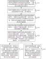
与上述实施例中的电池组加热系统对应,本发明实施例还提供了一种电池组加热系统的控制方法。图3为本发明实施例中一种电池组加热系统的控制方法的流程图。如图3所示,该电池组加热系统的控制方法可包括步骤S101至步骤S103。Corresponding to the battery pack heating system in the above embodiments, the embodiment of the present invention further provides a control method of the battery pack heating system. FIG. 3 is a flowchart of a control method of a battery pack heating system in an embodiment of the present invention. As shown in FIG. 3 , the control method of the battery pack heating system may include steps S101 to S103 .
在步骤S101中,电池管理模块获取电池组的状态参数,若电池组的状态参数满足预设低温低电量条件,向整车控制器和辅助充电支路控制模块分别发送低温低电量加热请求指令。In step S101, the battery management module obtains the state parameters of the battery pack, and if the state parameters of the battery pack meet the preset low temperature and low battery conditions, respectively sends low temperature and low battery heating request commands to the vehicle controller and the auxiliary charging branch control module.
在一些示例中,状态参数包括温度和荷电状态,预设低温低电量条件包括温度低于加热温度阈值,且荷电状态低于加热荷电状态要求阈值。比如,加热温度阈值大于等于-50℃,小于等于5℃。加热荷电状态要求阈值大于等于5%,小于100%。In some examples, the state parameters include temperature and state of charge, the preset low temperature low battery condition includes a temperature below a heating temperature threshold, and a state of charge below a heating state of charge requirement threshold. For example, the heating temperature threshold is greater than or equal to -50°C and less than or equal to 5°C. The heating state of charge requires the threshold to be greater than or equal to 5% and less than 100%.
在步骤S102中,辅助充电支路控制模块响应低温低电量加热请求指令,向辅助充电支路发送第一控制信号,以控制电池组加热系统与辅助充电支路导通,使得供电电源通过外接接口向电池组和/或电机传输能量。In step S102, the auxiliary charging branch control module sends a first control signal to the auxiliary charging branch in response to the low-temperature and low-battery heating request instruction to control the conduction between the battery pack heating system and the auxiliary charging branch, so that the power supply passes through the external interface Transfer energy to the battery pack and/or motor.
在步骤S103中,整车控制器响应低温低电量加热请求指令,向电机控制器发送第二控制信号,使电机控制器控制逆变器中的开关模块的通断,向电池管理模块发送第三控制信号,使电池管理模块控制主正开关的通断,使电池组与电机之间相互传递能量,以对电池组进行加热。In step S103, the vehicle controller sends a second control signal to the motor controller in response to the low temperature and low battery heating request instruction, so that the motor controller controls the on-off of the switch module in the inverter, and sends a third control signal to the battery management module. The control signal enables the battery management module to control the on-off of the main positive switch, so that the battery pack and the motor transfer energy to each other to heat the battery pack.
在本发明实施例中,电池管理模块确定电池组的状态参数满足预设低温低电量条件,向整车控制器和辅助充电支路控制模块分别发送低温低电量加热请求指令,以请求进行低温低电量加热模式。电池管理模块通过控制辅助充电支路控制模块,整车控制器通过控制电池管理模块和电机控制器,控制辅助充电支路、主正开关和逆变器中的开关模块,使辅助充电支路中供电电源向电池和/或电机传输能量,以使电池组和电机具有充足的可支持对电池组加热的能量。电池组与电机之间相互传递能量,形成电池组充、放电的循环,在电池组所在的回路中产生电流。交流电流可连续不断的通过电池组,使得电池组的内阻发热,从而在低电量的情况下也可实现对电池组的均匀、高效率的自加热。In the embodiment of the present invention, the battery management module determines that the state parameters of the battery pack meet the preset low temperature and low battery conditions, and sends low temperature and low battery heating request instructions to the vehicle controller and the auxiliary charging branch control module respectively to request low temperature and low battery. Electric heating mode. The battery management module controls the auxiliary charging branch control module, and the vehicle controller controls the auxiliary charging branch, the main positive switch and the switch module in the inverter by controlling the battery management module and the motor controller, so that the auxiliary charging branch can be controlled. The power supply transmits energy to the battery and/or the motor so that the battery pack and motor have sufficient energy to support heating of the battery pack. The battery pack and the motor transfer energy to each other, forming a cycle of charging and discharging the battery pack, and generating current in the circuit where the battery pack is located. The alternating current can continuously pass through the battery pack, causing the internal resistance of the battery pack to generate heat, so that even and high-efficiency self-heating of the battery pack can be achieved even in the case of low power.
与图1和图2所示的电池组加热系统对应,图4为本发明另一实施例中一种电池组加热系统的控制方法的流程图。图4与图3的不同之处在于,图4所示的电池组加热系统的控制方法还可包括步骤S104至步骤S107。Corresponding to the battery pack heating system shown in FIGS. 1 and 2 , FIG. 4 is a flowchart of a control method of a battery pack heating system in another embodiment of the present invention. The difference between FIG. 4 and FIG. 3 is that the control method of the battery pack heating system shown in FIG. 4 may further include steps S104 to S107.
在步骤S104中,电池管理模块向预充开关发送第三驱动信号,以控制预充开关导通,进行预充电。In step S104, the battery management module sends a third driving signal to the precharge switch to control the precharge switch to be turned on to perform precharge.
其中,电池组加热系统还包括与主正开关并联的预充支路,预充支路包括预充开关和预充电阻。Wherein, the battery pack heating system also includes a precharge branch connected in parallel with the main positive switch, and the precharge branch includes a precharge switch and a precharge resistor.
在步骤S105中,辅助充电支路控制模块响应低温低电量加热请求指令,向辅助开关模块发送第一控制信号,以控制辅助开关模块导通。In step S105, the auxiliary charging branch control module sends a first control signal to the auxiliary switch module in response to the low temperature and low battery heating request instruction to control the auxiliary switch module to be turned on.
其中,辅助充电支路还包括辅助开关模块。供电电源的电压高于电池组的当前电压。Wherein, the auxiliary charging branch further includes an auxiliary switch module. The voltage of the power supply is higher than the current voltage of the battery pack.
在步骤S106中,电机控制器响应第二控制信号,向逆变器中的部分开关模块发送第一驱动信号,以驱动部分开关模块周期性导通和断开,使电机接收供电电源传输来的能量,或使电机接收电池组传输来的能量,或使电机控制器向电池组传输能量。In step S106, in response to the second control signal, the motor controller sends a first drive signal to some of the switch modules in the inverter, so as to drive some of the switch modules to be turned on and off periodically, so that the motor receives the power transmitted from the power supply. energy, or make the motor receive energy from the battery pack, or make the motor controller transmit energy to the battery pack.
在步骤S107中,电池管理模块响应第三控制信号,向主正开关发送第二驱动信号,以驱动主正开关周期性导通和断开,使电池组接收供电电源传输来的能量,或使电池组接收电机传输来的能量,或使电池组向电机传输能量。In step S107, the battery management module sends a second driving signal to the main positive switch in response to the third control signal, so as to drive the main positive switch to turn on and off periodically, so that the battery pack receives the energy transmitted from the power supply, or makes The battery pack receives energy from the motor, or enables the battery pack to transmit energy to the motor.
在一些示例中,电池组加热系统还包括与逆变器并联的支撑电容。在第二驱动信号驱动主正开关导通的情况下,第一驱动信号驱动部分开关模块断开,以使电池组向支撑电容传输能量,或使电池组接收电机传输来的能量。在第一驱动信号驱动部分开关模块导通的情况下,第二驱动信号驱动主正开关断开,以使电机接收支撑电容传输来的能量。In some examples, the battery pack heating system also includes a support capacitor in parallel with the inverter. When the second drive signal drives the main positive switch to be turned on, the first drive signal drives the partial switch module to turn off, so that the battery pack transmits energy to the support capacitor, or the battery pack receives energy from the motor. When the first drive signal drives the partial switch module to be turned on, the second drive signal drives the main positive switch to turn off, so that the motor receives the energy transmitted from the support capacitor.
图5为本发明又一实施例中一种电池组加热系统的控制方法的流程图。图5与图3的不同之处在于,图5所示的电池组加热系统的控制方法还包括步骤S108至步骤S114。FIG. 5 is a flowchart of a control method of a battery pack heating system in another embodiment of the present invention. The difference between FIG. 5 and FIG. 3 is that the control method of the battery pack heating system shown in FIG. 5 further includes steps S108 to S114.
在步骤S108中,电池管理模块确定电池组的温度低于加热温度阈值,且电池组的荷电状态高于等于加热荷电状态要求阈值,向辅助充电支路控制模块发送低温加热请求指令。In step S108, the battery management module determines that the temperature of the battery pack is lower than the heating temperature threshold, and the state of charge of the battery pack is higher than or equal to the heating state of charge requirement threshold, and sends a low temperature heating request command to the auxiliary charging branch control module.
在步骤S109中,辅助充电支路控制模块响应低温加热请求指令,向辅助充电支路发送第四控制信号,以控制电池组加热系统与辅助充电支路断开。In step S109, the auxiliary charging branch control module sends a fourth control signal to the auxiliary charging branch in response to the low temperature heating request instruction to control the battery pack heating system to be disconnected from the auxiliary charging branch.
在步骤S110中,电池管理模块确定电池组的温度高于等于加热温度阈值,且电池组的荷电状态高于或等于加热荷电状态要求阈值,向整车控制器和辅助充电支路控制模块分别发送停止加热请求指令。In step S110, the battery management module determines that the temperature of the battery pack is higher than or equal to the heating temperature threshold, and the state of charge of the battery pack is higher than or equal to the required threshold of the heating state of charge, and reports to the vehicle controller and the auxiliary charging branch control module Send stop heating request commands respectively.
在步骤S111中,辅助充电支路控制模块响应停止加热请求指令,向辅助充电支路发送第五控制信号,以控制电池组加热系统与辅助充电支路断开。In step S111, the auxiliary charging branch control module sends a fifth control signal to the auxiliary charging branch in response to the heating stop request instruction to control the battery pack heating system to be disconnected from the auxiliary charging branch.
在步骤S112中,整车控制器响应停止加热请求指令,向电机控制器发送第六控制信号,向电池管理模块发送第七控制信号。In step S112, the vehicle controller sends a sixth control signal to the motor controller and a seventh control signal to the battery management module in response to the heating stop request instruction.
在步骤S113中,电机控制器响应第六控制信号,停止向逆变器中的部分开关模块发送第一驱动信号。In step S113, in response to the sixth control signal, the motor controller stops sending the first driving signal to some of the switch modules in the inverter.
在步骤S114中,电池管理模块响应第七控制信号,停止向主正开关发送第二驱动信号。In step S114, the battery management module stops sending the second driving signal to the main positive switch in response to the seventh control signal.
在一些示例中,电机控制器可调节第一驱动信号,从而调整逆变器的开关模块的开关频率和通断时长,以调节电池组加热系统对电池加热进行充、放电的电流。In some examples, the motor controller may adjust the first driving signal to adjust the switching frequency and on-off duration of the switch module of the inverter to adjust the current of the battery pack heating system for charging and discharging the battery heating.
比如,电池管理模块将获取的电池组的状态参数向整车控制器发送。状态参数包括荷电状态和温度。整车控制器将接收到的电池组的状态参数向电机控制器发送。电机控制器基于期望温升速率和接收到的电池组的状态参数,计算得到第一期望频率和第一期望占空比,并将第一驱动信号的频率和占空比调节为第一期望频率和第一期望占空比。For example, the battery management module sends the acquired state parameters of the battery pack to the vehicle controller. State parameters include state of charge and temperature. The vehicle controller sends the received state parameters of the battery pack to the motor controller. The motor controller calculates the first desired frequency and the first desired duty cycle based on the desired temperature rise rate and the received state parameters of the battery pack, and adjusts the frequency and duty cycle of the first drive signal to the first desired frequency and the first desired duty cycle.
又比如,所述电池管理模块将获取的所述电池组的荷电状态向所述整车控制器发送。所述整车控制器将接收到的所述电池组的荷电状态向所述电机控制器发送。所述电机控制器获取电机参数,并基于期望电机参数、所述电机参数和接收的所述电池组的荷电状态,计算得到第二期望频率和第二期望占空比,并将所述第一驱动信号的频率和占空比调节为所述第二期望频率和所述第二期望占空比。所述电机参数包括母线电流或所述电机的相电流。For another example, the battery management module sends the acquired state of charge of the battery pack to the vehicle controller. The vehicle controller sends the received state of charge of the battery pack to the motor controller. The motor controller acquires motor parameters, and calculates a second desired frequency and a second desired duty cycle based on the desired motor parameters, the motor parameters and the received state of charge of the battery pack, and calculates the second desired frequency and the second desired duty cycle. The frequency and duty cycle of a drive signal are adjusted to the second desired frequency and the second desired duty cycle. The motor parameters include bus currents or phase currents of the motor.
在一些示例中,电池管理模块可调节第二驱动信号,从而调整主正开关的开关频率和通断时长,以调节电池组加热系统对电池的加热。In some examples, the battery management module can adjust the second driving signal to adjust the switching frequency and on-off duration of the main positive switch to adjust the heating of the battery by the battery pack heating system.
比如,电池管理模块基于期望温升速率和获取的电池组的状态参数,计算得到第三期望频率和第三期望占空比,并将第二驱动信号的频率和占空比调节为第三期望频率和第三期望占空比。状态参数包括荷电状态和温度。For example, the battery management module calculates the third desired frequency and the third desired duty cycle based on the desired temperature rise rate and the acquired state parameters of the battery pack, and adjusts the frequency and duty cycle of the second driving signal to the third desired frequency and the third desired duty cycle. State parameters include state of charge and temperature.
又比如,电机控制器获取电机参数,并将电机参数向整车控制器发送。电机参数包括母线电流或电机的相电流。整车控制器将接收的电机参数向电池管理模块发送。电池管理模块基于期望电机参数、获取的电池组的荷电状态和接收的电机参数,计算得到第四期望频率和第四期望占空比,并将第二驱动信号的频率和占空比调节为第四期望频率和第四期望占空比。For another example, the motor controller obtains motor parameters and sends the motor parameters to the vehicle controller. Motor parameters include bus currents or motor phase currents. The vehicle controller sends the received motor parameters to the battery management module. The battery management module calculates and obtains a fourth desired frequency and a fourth desired duty cycle based on the desired motor parameters, the acquired state of charge of the battery pack, and the received motor parameters, and adjusts the frequency and duty cycle of the second drive signal as A fourth desired frequency and a fourth desired duty cycle.
在一些示例中,电机控制器获取电机参数,并将电机参数向整车控制器发送,电机参数包括母线电流或电机的相电流。整车控制器将接收到的电机参数向电池管理模块发送。电池管理模块根据电池组的当前温度、电池组的期望温度、电机参数和期望电机参数,得到电池组的预计加热时长。电池管理模块向整车控制器发送包括预计加热时长的时长信息。整车控制器接收时长信息,并发出用于提示预计加热时长的提示消息,以提示用户预计加热时长。In some examples, the motor controller obtains the motor parameters and sends the motor parameters to the vehicle controller, the motor parameters including the bus current or the phase current of the motor. The vehicle controller sends the received motor parameters to the battery management module. The battery management module obtains the expected heating time of the battery pack according to the current temperature of the battery pack, the expected temperature of the battery pack, the motor parameters and the expected motor parameters. The battery management module sends duration information including the estimated heating duration to the vehicle controller. The vehicle controller receives the duration information, and sends out a prompt message for prompting the estimated heating time, so as to prompt the user to estimate the heating time.
本发明实施例中电池组加热系统的控制方法的相关说明可参见上述实施例中电池组加热系统的相关内容,在此不再赘述。For the relevant description of the control method of the battery pack heating system in the embodiment of the present invention, reference may be made to the relevant content of the battery pack heating system in the above-mentioned embodiment, which will not be repeated here.
需要明确的是,本说明书中的各个实施例均采用递进的方式描述,各个实施例之间相同或相似的部分互相参见即可,每个实施例重点说明的都是与其他实施例的不同之处。对于控制方法实施例而言,相关之处可以参见电池组加热系统实施例的说明部分。本发明并不局限于上文所描述并在图中示出的特定步骤和结构。本领域的技术人员可以在领会本发明的精神之后,作出各种改变、修改和添加,或者改变步骤之间的顺序。并且,为了简明起见,这里省略对已知方法技术的详细描述。It should be clear that each embodiment in this specification is described in a progressive manner, and the same or similar parts of each embodiment may be referred to each other, and each embodiment focuses on the differences from other embodiments. place. For the embodiment of the control method, reference may be made to the description part of the embodiment of the battery pack heating system. The invention is not limited to the specific steps and structures described above and shown in the drawings. Those skilled in the art may make various changes, modifications and additions, or change the order between steps, after appreciating the spirit of the present invention. Also, for the sake of brevity, detailed descriptions of known methods and techniques are omitted here.
本领域技术人员应能理解,上述实施例均是示例性而非限制性的。在不同实施例中出现的不同技术特征可以进行组合,以取得有益效果。本领域技术人员在研究附图、说明书及权利要求书的基础上,应能理解并实现所揭示的实施例的其他变化的实施例。在权利要求书中,术语“包括”并不排除其他装置或步骤;不定冠词“一个”不排除多个;术语“第一”、“第二”用于标示名称而非用于表示任何特定的顺序。权利要求中的任何附图标记均不应被理解为对保护范围的限制。权利要求中出现的多个部分的功能可以由一个单独的硬件或软件模块来实现。某些技术特征出现在不同的从属权利要求中并不意味着不能将这些技术特征进行组合以取得有益效果。Those skilled in the art should understand that the above-mentioned embodiments are all illustrative and not restrictive. Different technical features appearing in different embodiments can be combined to achieve beneficial effects. Those skilled in the art should be able to understand and implement other variant embodiments of the disclosed embodiments on the basis of studying the drawings, the description and the claims. In the claims, the term "comprising" does not exclude other means or steps; the indefinite article "a" does not exclude a plurality; the terms "first" and "second" are used to designate names rather than to indicate any particular Order. Any reference signs in the claims shall not be construed as limiting the scope. The functions of several parts presented in the claims can be implemented by a single hardware or software module. The mere presence of certain technical features in different dependent claims does not imply that these features cannot be combined to advantage.
Claims (31)
Priority Applications (6)
| Application Number | Priority Date | Filing Date | Title |
|---|---|---|---|
| CN201910547455.8ACN110962692B (en) | 2019-06-24 | 2019-06-24 | Battery pack heating system and control method thereof |
| CN202011319289.5ACN112373351B (en) | 2019-06-24 | 2019-06-24 | Battery pack heating method |
| JP2020048833AJP6999725B2 (en) | 2019-06-24 | 2020-03-19 | Battery pack heating system and its control method |
| PCT/CN2020/087767WO2020259071A1 (en) | 2019-06-24 | 2020-04-29 | Battery pack heating system and control method therefor |
| EP20175237.5AEP3758131B1 (en) | 2019-06-24 | 2020-05-18 | Battery pack heating system and control method thereof |
| US17/385,879US11772515B2 (en) | 2019-06-24 | 2021-07-26 | Battery pack heating system and control method thereof |
Applications Claiming Priority (1)
| Application Number | Priority Date | Filing Date | Title |
|---|---|---|---|
| CN201910547455.8ACN110962692B (en) | 2019-06-24 | 2019-06-24 | Battery pack heating system and control method thereof |
Related Child Applications (1)
| Application Number | Title | Priority Date | Filing Date |
|---|---|---|---|
| CN202011319289.5ADivisionCN112373351B (en) | 2019-06-24 | 2019-06-24 | Battery pack heating method |
Publications (2)
| Publication Number | Publication Date |
|---|---|
| CN110962692A CN110962692A (en) | 2020-04-07 |
| CN110962692Btrue CN110962692B (en) | 2020-12-11 |
Family
ID=70028414
Family Applications (2)
| Application Number | Title | Priority Date | Filing Date |
|---|---|---|---|
| CN201910547455.8AActiveCN110962692B (en) | 2019-06-24 | 2019-06-24 | Battery pack heating system and control method thereof |
| CN202011319289.5AActiveCN112373351B (en) | 2019-06-24 | 2019-06-24 | Battery pack heating method |
Family Applications After (1)
| Application Number | Title | Priority Date | Filing Date |
|---|---|---|---|
| CN202011319289.5AActiveCN112373351B (en) | 2019-06-24 | 2019-06-24 | Battery pack heating method |
Country Status (5)
| Country | Link |
|---|---|
| US (1) | US11772515B2 (en) |
| EP (1) | EP3758131B1 (en) |
| JP (1) | JP6999725B2 (en) |
| CN (2) | CN110962692B (en) |
| WO (1) | WO2020259071A1 (en) |
Families Citing this family (43)
| Publication number | Priority date | Publication date | Assignee | Title |
|---|---|---|---|---|
| CN110962692B (en) | 2019-06-24 | 2020-12-11 | 宁德时代新能源科技股份有限公司 | Battery pack heating system and control method thereof |
| CN113733986A (en)* | 2020-05-29 | 2021-12-03 | 比亚迪股份有限公司 | Battery self-heating device, control method thereof and vehicle |
| CN113746152B (en)* | 2020-05-29 | 2024-09-10 | 比亚迪股份有限公司 | Battery energy processing device and vehicle |
| CN111391718B (en)* | 2020-06-04 | 2020-10-23 | 比亚迪股份有限公司 | Battery energy processing device, method and vehicle |
| CN111605439B (en)* | 2020-06-08 | 2021-08-27 | 安徽江淮汽车集团股份有限公司 | Motor auxiliary heating control method, device, equipment and storage medium |
| CN113904026A (en)* | 2020-06-22 | 2022-01-07 | 比亚迪股份有限公司 | Power battery self-heating control method, system and vehicle |
| CN113904025A (en)* | 2020-06-22 | 2022-01-07 | 比亚迪股份有限公司 | Power battery self-heating control method and system and automobile |
| DE102020209314A1 (en)* | 2020-07-23 | 2022-01-27 | Zf Friedrichshafen Ag | Device and method for providing operating energy for an additional drive for an electric vehicle and electric vehicle |
| CN114069102B (en)* | 2020-07-31 | 2024-06-18 | 比亚迪股份有限公司 | A self-heating method, device, system and electric vehicle for power battery |
| US20220102769A1 (en)* | 2020-09-30 | 2022-03-31 | GM Global Technology Operations LLC | Architecture for battery self heating |
| EP4056415A1 (en)* | 2021-03-08 | 2022-09-14 | Volvo Car Corporation | Method for heating a battery in a vehicle, control unit and vehicle |
| CN115139854B (en)* | 2021-03-31 | 2025-01-14 | 比亚迪股份有限公司 | Energy conversion device and control method thereof |
| CN113561847B (en)* | 2021-06-30 | 2024-03-22 | 安徽和鼎机电设备有限公司 | Lithium battery system and working method |
| CN115917836B (en)* | 2021-08-05 | 2024-01-30 | 宁德时代新能源科技股份有限公司 | Charge and discharge circuits, systems and control methods |
| KR102607669B1 (en)* | 2021-08-05 | 2023-11-29 | 컨템포러리 엠퍼렉스 테크놀로지 씨오., 리미티드 | Power battery heating system and its control method and control circuit |
| WO2023028817A1 (en)* | 2021-08-31 | 2023-03-09 | 宁德时代新能源科技股份有限公司 | Battery heating method, battery-heating system and powered apparatus |
| CN113696789A (en)* | 2021-08-31 | 2021-11-26 | 东风小康汽车有限公司重庆分公司 | Low-temperature direct-current heating control method for battery |
| FR3127332B1 (en) | 2021-09-21 | 2025-07-04 | Renault Sas | Method for controlling a motor vehicle battery heating element |
| CN113937848A (en)* | 2021-09-27 | 2022-01-14 | 东集技术股份有限公司 | A battery charging control device and battery charging control method |
| DE102021126347A1 (en) | 2021-10-12 | 2023-04-13 | Audi Aktiengesellschaft | Method for preparing a drive battery for a selected battery operation and electric drive device and motor vehicle |
| CN114094234A (en)* | 2021-10-26 | 2022-02-25 | 华人运通(江苏)技术有限公司 | Battery heating control method, device, equipment and medium |
| EP4274002A4 (en)* | 2021-10-29 | 2025-02-26 | Contemporary Amperex Technology (Hong Kong) Limited | Power battery heating method and heating system |
| CN114374199B (en)* | 2022-01-24 | 2024-08-13 | 阳光电源股份有限公司 | Energy storage system |
| CN116552335B (en)* | 2022-01-29 | 2024-10-11 | 比亚迪股份有限公司 | Heating circuit of power battery and electric vehicle |
| CN116080422A (en)* | 2022-02-17 | 2023-05-09 | 华为电动技术有限公司 | Power battery pack device, heating control system and electric automobile |
| CN114552643A (en)* | 2022-02-28 | 2022-05-27 | 阳光电源股份有限公司 | Energy storage system |
| CN114834319B (en)* | 2022-03-04 | 2023-06-06 | 华为电动技术有限公司 | Power battery heating method and device, chip system and electric automobile |
| CN115377554B (en)* | 2022-04-24 | 2023-12-22 | 宁德时代新能源科技股份有限公司 | Power utilization device, heating control method and device thereof and medium |
| CN115377555B (en)* | 2022-04-26 | 2024-09-17 | 宁德时代新能源科技股份有限公司 | Battery heating control method, device, equipment and storage medium |
| CN114889497B (en)* | 2022-04-28 | 2024-05-07 | 重庆大学 | A composite heating device and control method for electric vehicle power system |
| CN118044042A (en)* | 2022-04-29 | 2024-05-14 | 宁德时代新能源科技股份有限公司 | Control method of battery heating system and heating system |
| CN114899931A (en)* | 2022-06-09 | 2022-08-12 | 杭州海康威视数字技术股份有限公司 | Energy supply system and method for electronic equipment |
| CN115275439A (en)* | 2022-07-04 | 2022-11-01 | 盐城国投中科新能源科技有限公司 | A rapid heating device and control method of lithium battery system for starting power supply |
| EP4557598A4 (en)* | 2022-08-24 | 2025-08-13 | Contemporary Amperex Technology Co Ltd | Regulation circuit and system for battery, and regulation method |
| CN118107441B (en)* | 2022-11-30 | 2025-09-16 | 比亚迪股份有限公司 | Battery dynamic balancing device, control method thereof and vehicle |
| US12304435B2 (en)* | 2022-12-07 | 2025-05-20 | Hyundai Motor Company | Vehicle charge port defroster |
| CN116053660B (en)* | 2022-12-07 | 2025-01-07 | 华为数字能源技术有限公司 | Energy storage heating control method, energy storage system and photovoltaic storage system |
| CN219600993U (en)* | 2023-02-03 | 2023-08-29 | 宁德时代新能源科技股份有限公司 | Battery control modules, battery packs and battery control systems |
| CN119948671A (en)* | 2023-03-14 | 2025-05-06 | 宁德时代新能源科技股份有限公司 | Charging method, device, battery pack, electronic device and computer-readable storage medium |
| CN116454472A (en)* | 2023-04-19 | 2023-07-18 | 江苏汇智高端工程机械创新中心有限公司 | Power battery self-heating system and method based on electric drive inverter reconstruction |
| CN116995804B (en)* | 2023-06-25 | 2024-04-05 | 安徽博达项目管理咨询有限公司 | Communication base station power supply parallel monitoring method |
| CN116960526B (en)* | 2023-09-18 | 2024-08-16 | 浙江艾罗网络能源技术股份有限公司 | Battery heating method, device and system, and battery pack |
| CN120287873B (en)* | 2025-06-13 | 2025-09-26 | 深蓝汽车科技有限公司 | Charging heating circuit, method and system and vehicle |
Citations (9)
| Publication number | Priority date | Publication date | Assignee | Title |
|---|---|---|---|---|
| JPH09259937A (en)* | 1996-03-22 | 1997-10-03 | Mitsubishi Chem Corp | Preheating method and preheating device for secondary battery |
| CN102668229A (en)* | 2010-07-29 | 2012-09-12 | 松下电器产业株式会社 | Battery temperature elevating circuit and battery temperature elevating device |
| CN103560304A (en)* | 2013-11-19 | 2014-02-05 | 东风汽车公司 | Heating control method of power battery pack of electric vehicle |
| CN204289653U (en)* | 2014-11-28 | 2015-04-22 | 富奥汽车零部件股份有限公司 | A kind of heating of battery structure being built in motor driven systems |
| CN104779652A (en)* | 2014-01-09 | 2015-07-15 | 同济大学 | Power battery charger by using AC charging and discharging for quick preheating |
| EP2865044B1 (en)* | 2012-06-22 | 2016-11-02 | Renault S.A.S. | Device for heating a storage battery of a motor vehicle and corresponding heating method |
| CN107666028A (en)* | 2017-08-16 | 2018-02-06 | 同济大学 | A kind of lithium ion battery for electric vehicle low temperature exchanges heater |
| CN108682909A (en)* | 2018-05-22 | 2018-10-19 | 宁德时代新能源科技股份有限公司 | Battery pack system, control method thereof and management equipment |
| CN108847513A (en)* | 2018-05-08 | 2018-11-20 | 北京航空航天大学 | A kind of lithium ion battery low-temperature heat control method |
Family Cites Families (20)
| Publication number | Priority date | Publication date | Assignee | Title |
|---|---|---|---|---|
| US8452490B2 (en)* | 2009-12-14 | 2013-05-28 | Control Solutions LLC | Electronic circuit for charging and heating a battery |
| KR101230353B1 (en) | 2010-01-28 | 2013-02-06 | 주식회사 엘지화학 | Battery Pack System of Improving Low Temperature Performance Using Internal Resistance of Cell |
| JP5502603B2 (en)* | 2010-06-04 | 2014-05-28 | 本田技研工業株式会社 | Vehicle battery heating device |
| CN103419663B (en)* | 2012-05-22 | 2015-11-25 | 比亚迪股份有限公司 | The power system of electronlmobil, electronlmobil and heating of battery method |
| JP5626294B2 (en)* | 2012-08-29 | 2014-11-19 | トヨタ自動車株式会社 | Power storage system |
| JP5849917B2 (en) | 2012-09-28 | 2016-02-03 | 株式会社豊田自動織機 | Battery temperature rise control device for electric vehicle |
| JP2014089915A (en) | 2012-10-31 | 2014-05-15 | Sumitomo Electric Ind Ltd | Power supply system and electric vehicle |
| CN103066662B (en)* | 2013-01-07 | 2015-08-05 | 雷星亮 | emergency power supply |
| US20140285135A1 (en)* | 2013-03-22 | 2014-09-25 | Ec Power, Llc | Systems for heating a battery and processes thereof |
| CN103427137B (en)* | 2013-08-20 | 2015-10-07 | 重庆长安汽车股份有限公司 | The low-temperature charging heating system of power battery of pure electric automobile and heating means |
| US10647211B2 (en)* | 2015-09-28 | 2020-05-12 | Honda Motor Co., Ltd. | Power consumption control device |
| CN105762434B (en) | 2016-05-16 | 2018-12-07 | 北京理工大学 | A kind of power-supply system and vehicle with self heating function |
| CN106229583B (en)* | 2016-07-25 | 2018-08-03 | 北京理工大学 | A kind of electrical storage device heating means heated based on LC resonance |
| US10272758B2 (en)* | 2016-11-02 | 2019-04-30 | Proterra Inc. | Battery system of an electric vehicle |
| CN106965700A (en)* | 2017-04-28 | 2017-07-21 | 北京新能源汽车股份有限公司 | Electric automobile heating charging circuit and charging method |
| US11500346B2 (en)* | 2019-04-25 | 2022-11-15 | David Valin | Energy generation, solar panel racking switching pumping apparatus mechanism and system |
| CN112706657B (en) | 2018-12-29 | 2022-12-23 | 宁德时代新能源科技股份有限公司 | Control method, battery management module, motor controller and medium |
| CN110962631B (en) | 2018-12-29 | 2020-11-17 | 宁德时代新能源科技股份有限公司 | Battery heating system and control method thereof |
| CN110970965B (en)* | 2019-06-24 | 2020-11-06 | 宁德时代新能源科技股份有限公司 | Switch control device and method, motor controller and battery pack heating control system |
| CN110962692B (en)* | 2019-06-24 | 2020-12-11 | 宁德时代新能源科技股份有限公司 | Battery pack heating system and control method thereof |
- 2019
- 2019-06-24CNCN201910547455.8Apatent/CN110962692B/enactiveActive
- 2019-06-24CNCN202011319289.5Apatent/CN112373351B/enactiveActive
- 2020
- 2020-03-19JPJP2020048833Apatent/JP6999725B2/enactiveActive
- 2020-04-29WOPCT/CN2020/087767patent/WO2020259071A1/ennot_activeCeased
- 2020-05-18EPEP20175237.5Apatent/EP3758131B1/enactiveActive
- 2021
- 2021-07-26USUS17/385,879patent/US11772515B2/enactiveActive
Patent Citations (9)
| Publication number | Priority date | Publication date | Assignee | Title |
|---|---|---|---|---|
| JPH09259937A (en)* | 1996-03-22 | 1997-10-03 | Mitsubishi Chem Corp | Preheating method and preheating device for secondary battery |
| CN102668229A (en)* | 2010-07-29 | 2012-09-12 | 松下电器产业株式会社 | Battery temperature elevating circuit and battery temperature elevating device |
| EP2865044B1 (en)* | 2012-06-22 | 2016-11-02 | Renault S.A.S. | Device for heating a storage battery of a motor vehicle and corresponding heating method |
| CN103560304A (en)* | 2013-11-19 | 2014-02-05 | 东风汽车公司 | Heating control method of power battery pack of electric vehicle |
| CN104779652A (en)* | 2014-01-09 | 2015-07-15 | 同济大学 | Power battery charger by using AC charging and discharging for quick preheating |
| CN204289653U (en)* | 2014-11-28 | 2015-04-22 | 富奥汽车零部件股份有限公司 | A kind of heating of battery structure being built in motor driven systems |
| CN107666028A (en)* | 2017-08-16 | 2018-02-06 | 同济大学 | A kind of lithium ion battery for electric vehicle low temperature exchanges heater |
| CN108847513A (en)* | 2018-05-08 | 2018-11-20 | 北京航空航天大学 | A kind of lithium ion battery low-temperature heat control method |
| CN108682909A (en)* | 2018-05-22 | 2018-10-19 | 宁德时代新能源科技股份有限公司 | Battery pack system, control method thereof and management equipment |
Also Published As
| Publication number | Publication date |
|---|---|
| JP6999725B2 (en) | 2022-01-19 |
| EP3758131A1 (en) | 2020-12-30 |
| EP3758131B1 (en) | 2022-08-31 |
| CN112373351A (en) | 2021-02-19 |
| JP2021002513A (en) | 2021-01-07 |
| US11772515B2 (en) | 2023-10-03 |
| WO2020259071A1 (en) | 2020-12-30 |
| US20210354592A1 (en) | 2021-11-18 |
| CN110962692A (en) | 2020-04-07 |
| CN112373351B (en) | 2022-04-22 |
Similar Documents
| Publication | Publication Date | Title |
|---|---|---|
| CN110962692B (en) | Battery pack heating system and control method thereof | |
| US11338702B2 (en) | Control system and method for battery pack heating system, and battery pack heating management system | |
| US12100819B2 (en) | Switch control device and method, motor controller, and battery pack heating control system | |
| KR102278905B1 (en) | Battery heating system and control method thereof | |
| KR102455823B1 (en) | Battery heating system and control method thereof | |
| US11699957B2 (en) | Energy conversion system, energy conversion method, and power system | |
| KR102463393B1 (en) | battery heating system | |
| US10797364B2 (en) | Power supply system of vehicle | |
| US11349162B2 (en) | Automotive battery heater | |
| CN103460550B (en) | Power conversion equipment, electric vehicles and charging systems for electric vehicles | |
| EP4096053B1 (en) | Battery control circuit, battery and electronic device | |
| JP2013229336A (en) | Battery temperature rising system | |
| CN117656948B (en) | Battery self-heating system and vehicle | |
| JP2013070547A (en) | Power conversion device | |
| JP2013021803A (en) | Electric vehicle drive system | |
| JP2016119167A (en) | Power source system | |
| CN110723005A (en) | On-board charger for electric vehicle and control method thereof, electric vehicle | |
| CN110661323A (en) | On-board charger for electric vehicle and control method thereof, electric vehicle |
Legal Events
| Date | Code | Title | Description |
|---|---|---|---|
| PB01 | Publication | ||
| PB01 | Publication | ||
| SE01 | Entry into force of request for substantive examination | ||
| SE01 | Entry into force of request for substantive examination | ||
| GR01 | Patent grant | ||
| GR01 | Patent grant | ||
| TR01 | Transfer of patent right | Effective date of registration:20220120 Address after:352100 science and technology building, No. 2, Xingang Road, Zhangwan Town, Jiaocheng District, Ningde City, Fujian Province Patentee after:Ningde Shidai Runzhi Software Technology Co.,Ltd. Address before:352100 Xingang Road, Zhangwan Town, Jiaocheng District, Ningde, Fujian 2 Patentee before:Contemporary Amperex Technology Co.,Ltd. | |
| TR01 | Transfer of patent right |