CN110962146B - System and method for manipulating a robotic device - Google Patents
System and method for manipulating a robotic deviceDownload PDFInfo
- Publication number
- CN110962146B CN110962146BCN201911278371.5ACN201911278371ACN110962146BCN 110962146 BCN110962146 BCN 110962146BCN 201911278371 ACN201911278371 ACN 201911278371ACN 110962146 BCN110962146 BCN 110962146B
- Authority
- CN
- China
- Prior art keywords
- component
- opening
- connection hole
- human
- top sheet
- Prior art date
- Legal status (The legal status is an assumption and is not a legal conclusion. Google has not performed a legal analysis and makes no representation as to the accuracy of the status listed.)
- Active
Links
Images


Classifications
- B—PERFORMING OPERATIONS; TRANSPORTING
- B25—HAND TOOLS; PORTABLE POWER-DRIVEN TOOLS; MANIPULATORS
- B25J—MANIPULATORS; CHAMBERS PROVIDED WITH MANIPULATION DEVICES
- B25J1/00—Manipulators positioned in space by hand
- B25J1/02—Manipulators positioned in space by hand articulated or flexible
- B—PERFORMING OPERATIONS; TRANSPORTING
- B25—HAND TOOLS; PORTABLE POWER-DRIVEN TOOLS; MANIPULATORS
- B25J—MANIPULATORS; CHAMBERS PROVIDED WITH MANIPULATION DEVICES
- B25J13/00—Controls for manipulators
- B25J13/08—Controls for manipulators by means of sensing devices, e.g. viewing or touching devices
- B—PERFORMING OPERATIONS; TRANSPORTING
- B25—HAND TOOLS; PORTABLE POWER-DRIVEN TOOLS; MANIPULATORS
- B25J—MANIPULATORS; CHAMBERS PROVIDED WITH MANIPULATION DEVICES
- B25J13/00—Controls for manipulators
- B25J13/006—Controls for manipulators by means of a wireless system for controlling one or several manipulators
- B—PERFORMING OPERATIONS; TRANSPORTING
- B25—HAND TOOLS; PORTABLE POWER-DRIVEN TOOLS; MANIPULATORS
- B25J—MANIPULATORS; CHAMBERS PROVIDED WITH MANIPULATION DEVICES
- B25J13/00—Controls for manipulators
- B25J13/08—Controls for manipulators by means of sensing devices, e.g. viewing or touching devices
- B25J13/088—Controls for manipulators by means of sensing devices, e.g. viewing or touching devices with position, velocity or acceleration sensors
- B—PERFORMING OPERATIONS; TRANSPORTING
- B25—HAND TOOLS; PORTABLE POWER-DRIVEN TOOLS; MANIPULATORS
- B25J—MANIPULATORS; CHAMBERS PROVIDED WITH MANIPULATION DEVICES
- B25J15/00—Gripping heads and other end effectors
- B25J15/0009—Gripping heads and other end effectors comprising multi-articulated fingers, e.g. resembling a human hand
- B—PERFORMING OPERATIONS; TRANSPORTING
- B25—HAND TOOLS; PORTABLE POWER-DRIVEN TOOLS; MANIPULATORS
- B25J—MANIPULATORS; CHAMBERS PROVIDED WITH MANIPULATION DEVICES
- B25J3/00—Manipulators of leader-follower type, i.e. both controlling unit and controlled unit perform corresponding spatial movements
- B25J3/04—Manipulators of leader-follower type, i.e. both controlling unit and controlled unit perform corresponding spatial movements involving servo mechanisms
- G—PHYSICS
- G06—COMPUTING OR CALCULATING; COUNTING
- G06F—ELECTRIC DIGITAL DATA PROCESSING
- G06F3/00—Input arrangements for transferring data to be processed into a form capable of being handled by the computer; Output arrangements for transferring data from processing unit to output unit, e.g. interface arrangements
- G06F3/01—Input arrangements or combined input and output arrangements for interaction between user and computer
- G06F3/011—Arrangements for interaction with the human body, e.g. for user immersion in virtual reality
- G06F3/014—Hand-worn input/output arrangements, e.g. data gloves
Landscapes
- Engineering & Computer Science (AREA)
- Robotics (AREA)
- Mechanical Engineering (AREA)
- Human Computer Interaction (AREA)
- General Engineering & Computer Science (AREA)
- Theoretical Computer Science (AREA)
- Physics & Mathematics (AREA)
- General Physics & Mathematics (AREA)
- Computer Networks & Wireless Communication (AREA)
- Manipulator (AREA)
Abstract
Description
Translated fromChinese技术领域Technical Field
本发明涉及机器人设备技术领域,特别涉及一种机器人设备的操纵系统和方法。The present invention relates to the technical field of robot equipment, and in particular to a control system and method of robot equipment.
背景技术Background Art
机器人设备被越来越多地用于各种各样的应用程序中,例如医疗保健应用程序、生产应用程序、和用户辅助应用程序。随着机器人设备越来越普遍地被使用,不了解机器人设备的编程和控制的终端用户也可能需要使用此类设备。例如,残疾人可能需要使用服务机器人来帮助他或她拿物品或上下床。但是,残疾人可能没有接受到如何控制机器人执行任务的机器人编程培训。Robotic devices are increasingly being used in a variety of applications, such as healthcare applications, manufacturing applications, and user assistance applications. As robotic devices become more commonly used, end users who do not understand the programming and control of robotic devices may need to use such devices. For example, a person with a disability may need to use a service robot to help him or her pick up items or get in and out of bed. However, the person with a disability may not have received robotic programming training on how to control the robot to perform tasks.
从教育和学习的角度来看,可能希望通过可定制的自学项目向各个年龄段和具有不同兴趣的人们介绍机器人技术、工程学、软件编程的概念。大多数商用机器人系统都是现成的成品,不能容易地进行重新编程使其超出预设的用途。From an education and learning perspective, it may be desirable to introduce the concepts of robotics, engineering, and software programming to people of all ages and interests through customizable self-study programs. Most commercial robotic systems are off-the-shelf and cannot be easily reprogrammed for purposes beyond their intended purpose.
因此,需要为所有年龄和各种兴趣的人提供与机器人系统设计和编程有关的完全可定制的学习体验。Therefore, there is a need to provide fully customizable learning experiences related to designing and programming robotic systems for people of all ages and with a variety of interests.
此外,结合本申请的附图和背景,根据随后的具体实施方式和权利要求,其他期望的特征也将显现。Furthermore, other desirable features will become apparent from the subsequent detailed description and the claims, taken in conjunction with the drawings and background of the application.
发明内容Summary of the invention
本发明的主要目的是提出一种机器人设备的操作系统和操纵方法,旨在提供一种能精度模仿人手功能的机器人设备的操作系统。The main purpose of the present invention is to provide an operating system and a manipulation method for a robot device, aiming to provide an operating system for a robot device that can accurately imitate the functions of a human hand.
在本申请的一些实施例公开了一种机器人设备的操作系统。所述系统包括:Some embodiments of the present application disclose an operating system for a robot device. The system includes:
人机交互设备,用于获取与使用该人机交互设备的用户手指的位置和/或动作相关联的信息;及A human-computer interaction device for acquiring information associated with a position and/or movement of a finger of a user using the human-computer interaction device; and
机器人设备,用于实时模拟用户手指的位置和/或动作,A robotic device for simulating the position and/or movement of a user's fingers in real time,
其中,所述机器人设备与人机交互设备通信连接。Wherein, the robot device is communicatively connected with the human-computer interaction device.
在一些实施例中,所述人机交互设备具有一手套,所述手套套设于所述机器人设备上。In some embodiments, the human-machine interaction device has a glove, and the glove is mounted on the robot device.
在一些实施例中,所述手套包括若干传感器,该多个传感器用于获取与用户手指的位置和/或动作相关联的信息。In some embodiments, the glove includes a plurality of sensors for acquiring information associated with the position and/or movement of the user's fingers.
在一些实施例中,所述手套包括一第一处理器;所述机器人设备包括一第二处理器,所述第二处理器用于与手套的第一处理器通信连接。In some embodiments, the glove includes a first processor; the robotic device includes a second processor, and the second processor is used to communicate with the first processor of the glove.
在一些实施例中,所述机器人设备包括一机械臂,所述机械臂具有多个类似于手指的组件。In some embodiments, the robotic device includes a robotic arm having a plurality of finger-like components.
在一些实施例中,所述机器人设备还包括运动控制机构,响应于第二处理器生成的信号,所述运动控制机构用于来控制多个组件的运动。In some embodiments, the robotic device further comprises a motion control mechanism for controlling the motion of the plurality of components in response to the signal generated by the second processor.
在一些实施例中,所述运动控制机构包括多个摇动臂、用于驱动摇动臂的多个电机、与所述摇动臂相连接的多个牵引线,每一牵引线、每一摇动臂及每一电机与一对应的类似手指的组件连接。In some embodiments, the motion control mechanism includes multiple rocking arms, multiple motors for driving the rocking arms, and multiple traction lines connected to the rocking arms, and each traction line, each rocking arm and each motor is connected to a corresponding finger-like component.
在一些实施例中,所述机器人设备由3D打印技术制得。In some embodiments, the robotic device is made by 3D printing technology.
本申请还提供一种机器人设备的操纵方法,应用于上述机器人设备的操作系统,所述方法包括以下步骤:The present application also provides a method for manipulating a robot device, which is applied to the operating system of the robot device, and the method comprises the following steps:
通过人机交互设备获取与使用该人机交互设备的用户手指的位置和/或动作相关联的信息;及Acquiring, through a human-computer interaction device, information associated with a position and/or movement of a finger of a user using the human-computer interaction device; and
通过机器人设备实时模拟用户手指的位置和/或动作。The position and/or movement of the user's fingers is simulated in real time by the robotic device.
在一些实施例中,还包括以下步骤:In some embodiments, the following steps are also included:
套设对应的手套于机器人设备上;及Putting corresponding gloves on the robot device; and
通过手套获取与用户手指的位置和/或动作相关联的信息。Information associated with the position and/or movement of the user's fingers is obtained through the glove.
本申请的技术方案中,所述系统包括人机交互设备和机器人设备,所述机器人设备与人机交互设备通信连接。所述人机交互设备用于获取与使用该人机交互设备的用户手指的位置和/或动作相关联的信息。所述机器人设备用于实时模拟用户手指的位置和/或动作。所述机器人设备可以分析肌肉发出的电信号,从而使其智能地适应和学习每个截肢者所需的手势,从而以前所未有的精度模仿人手的功能。In the technical solution of the present application, the system includes a human-computer interaction device and a robot device, and the robot device is communicatively connected to the human-computer interaction device. The human-computer interaction device is used to obtain information associated with the position and/or movement of the finger of the user using the human-computer interaction device. The robot device is used to simulate the position and/or movement of the user's finger in real time. The robot device can analyze the electrical signals emitted by the muscles, so that it can intelligently adapt to and learn the gestures required by each amputee, thereby imitating the functions of the human hand with unprecedented accuracy.
附图说明BRIEF DESCRIPTION OF THE DRAWINGS
为了更清楚地说明本申请实施例或现有技术中的技术方案,下面将对实施例或现有技术描述中所需要使用的附图作简单地介绍,显而易见地,下面描述中的附图仅仅是本申请的一些实施例,对于本领域普通技术人员来讲,在不付出创造性劳动的前提下,还可以根据这些附图示出的结构获得其他的附图。In order to more clearly illustrate the embodiments of the present application or the technical solutions in the prior art, the drawings required for use in the embodiments or the description of the prior art will be briefly introduced below. Obviously, the drawings described below are only some embodiments of the present application. For ordinary technicians in this field, other drawings can be obtained based on the structures shown in these drawings without paying any creative work.
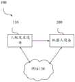
图1是本申请一实施例的机器人系统的方块图。FIG. 1 is a block diagram of a robot system according to an embodiment of the present application.
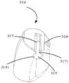
图2是本申请一实施例的机器人设备的第一组件的基片的结构示意图。FIG. 2 is a schematic structural diagram of a substrate of a first component of a robot device according to an embodiment of the present application.
图3是图2所示基片另一角度的结构示意图。FIG. 3 is a schematic structural diagram of the substrate shown in FIG. 2 from another angle.
图4是本申请一实施例的机器人设备的第一组件的顶片的结构示意图。FIG. 4 is a schematic structural diagram of a top plate of a first component of a robot device according to an embodiment of the present application.
图5是本申请一实施例的机器人设备的连接器的结构示意图。FIG. 5 is a schematic structural diagram of a connector of a robot device according to an embodiment of the present application.
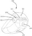
图6是本申请一实施例的机器人设备的第二组件的基片的结构示意图。FIG. 6 is a schematic structural diagram of a substrate of a second component of a robot device according to an embodiment of the present application.
图7是本申请一实施例的机器人设备的第二组件的中间件的结构示意图。FIG. 7 is a schematic diagram of the structure of the middleware of the second component of the robot device according to an embodiment of the present application.
图8是图7所示中间件另一角度的结构示意图。FIG. 8 is a schematic structural diagram of the middle piece shown in FIG. 7 from another angle.
图9是本申请一实施例的机器人设备的第二组件的顶片的结构示意图。FIG. 9 is a schematic structural diagram of a top plate of a second component of a robot device according to an embodiment of the present application.
图10是本申请一实施例的机器人设备的第三组件的基片的结构示意图。FIG. 10 is a schematic structural diagram of a substrate of a third component of a robot device according to an embodiment of the present application.
图11是图10所示基片另一角度的结构示意图。FIG. 11 is a schematic structural diagram of the substrate shown in FIG. 10 from another angle.
图12是本申请一实施例的机器人设备的第三组件的顶片的结构示意图。FIG. 12 is a schematic structural diagram of a top plate of a third component of a robot device according to an embodiment of the present application.
图13是本申请一实施例的机器人设备的第三组件的中间件的结构示意图。FIG. 13 is a schematic diagram of the structure of the middleware of the third component of the robot device according to an embodiment of the present application.
图14是图13所示中间件另一角度的结构示意图。FIG. 14 is a schematic structural diagram of the middle piece shown in FIG. 13 from another angle.
图15是本申请一实施例的机器人设备的第四组件的基片的结构示意图。FIG. 15 is a schematic diagram of the structure of a substrate of a fourth component of a robot device according to an embodiment of the present application.
图16是本申请一实施例的机器人设备的第四组件的中间件的结构示意图。FIG. 16 is a schematic diagram of the structure of the middleware of the fourth component of the robot device according to an embodiment of the present application.
图17是图16所示中间件另一角度的结构示意图。FIG. 17 is a schematic structural diagram of the middle piece shown in FIG. 16 from another angle.
图18是本申请一实施例的机器人设备的第四组件的顶片的结构示意图。FIG. 18 is a schematic structural diagram of the top plate of the fourth component of the robot device according to an embodiment of the present application.
图19是本申请一实施例的机器人设备的第五组件的基片的结构示意图。FIG. 19 is a schematic diagram of the structure of a substrate of the fifth component of the robot device according to an embodiment of the present application.
图20是本申请一实施例的机器人设备的第五组件的中间件的结构示意图。FIG. 20 is a schematic diagram of the structure of the middleware of the fifth component of the robot device according to an embodiment of the present application.
图21是图20所示中间件另一角度的结构示意图。FIG. 21 is a schematic structural diagram of the middle piece shown in FIG. 20 from another angle.
图22是本申请一实施例的机器人设备的第五组件的顶片的结构示意图。FIG. 22 is a schematic diagram of the structure of the top plate of the fifth component of the robot device according to an embodiment of the present application.
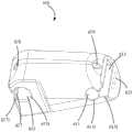
图23是本申请一实施例的机器人设备的结构示意图。FIG. 23 is a schematic diagram of the structure of a robot device according to an embodiment of the present application.
图24是图23所示机器人设备另一角度的结构示意图。FIG. 24 is a schematic structural diagram of the robot device shown in FIG. 23 from another angle.
图25是本申请一实施例的机器人设备的前手掌的结构示意图。FIG. 25 is a schematic structural diagram of the front palm of a robot device according to an embodiment of the present application.
图26是图25所示前手掌另一角度的结构示意图。FIG. 26 is a schematic structural diagram of the front palm shown in FIG. 25 from another angle.
图27是本申请一实施例的机器人设备的后手掌的结构示意图。FIG. 27 is a schematic diagram of the structure of the rear palm of the robot device according to an embodiment of the present application.
图28是本申请的一实施例的机械臂的组装方法的流程图。FIG. 28 is a flow chart of a method for assembling a robot arm according to an embodiment of the present application.
其中,附图标记说明如下:The reference numerals are described as follows:


本申请目的的实现、功能特点及优点将结合实施例,参照附图做进一步说明。The realization of the purpose, functional features and advantages of this application will be further explained in conjunction with embodiments and with reference to the accompanying drawings.
具体实施方式DETAILED DESCRIPTION
下面将结合本申请实施例中的附图,对本申请实施例中的技术方案进行清楚、完整地描述,显然,所描述的实施例仅仅是本申请的一部分实施例,而不是全部的实施例。基于本申请中的实施例,本领域普通技术人员在没有作出创造性劳动前提下所获得的所有其他实施例,都属于本申请保护的范围。The following will be combined with the drawings in the embodiments of the present application to clearly and completely describe the technical solutions in the embodiments of the present application. Obviously, the described embodiments are only part of the embodiments of the present application, not all of the embodiments. Based on the embodiments in the present application, all other embodiments obtained by ordinary technicians in this field without creative work are within the scope of protection of this application.
需要说明,本申请实施例中所有方向性指示(诸如上、下、左、右、前、后……)仅用于解释在某一特定姿态(如附图所示)下各部件之间的相对位置关系、运动情况等,如果该特定姿态发生改变时,则该方向性指示也相应地随之改变。It should be noted that all directional indications in the embodiments of the present application (such as up, down, left, right, front, back, etc.) are only used to explain the relative position relationship, movement status, etc. between the components under a certain specific posture (as shown in the accompanying drawings). If the specific posture changes, the directional indication will also change accordingly.
在本申请中,除非另有明确的规定和限定,术语“连接”、“固定”等应做广义理解,例如,“固定”可以是固定连接,也可以是可拆卸连接,或成一体;可以是机械连接,也可以是电连接;可以是直接相连,也可以通过中间媒介间接相连,可以是两个元件内部的连通或两个元件的相互作用关系,除非另有明确的限定。对于本领域的普通技术人员而言,可以根据具体情况理解上述术语在本申请中的具体含义。In this application, unless otherwise clearly specified and limited, the terms "connection", "fixation", etc. should be understood in a broad sense. For example, "fixation" can be a fixed connection, a detachable connection, or an integral connection; it can be a mechanical connection or an electrical connection; it can be a direct connection or an indirect connection through an intermediate medium, it can be the internal connection of two elements or the interaction relationship between two elements, unless otherwise clearly defined. For ordinary technicians in this field, the specific meanings of the above terms in this application can be understood according to specific circumstances.
另外,在本申请中如涉及“第一”、“第二”等的描述仅用于描述目的,而不能理解为指示或暗示其相对重要性或者隐含指明所指示的技术特征的数量。由此,限定有“第一”、“第二”的特征可以明示或者隐含地包括至少一个该特征。另外,各个实施例之间的技术方案可以相互结合,但是必须是以本领域普通技术人员能够实现为基础,当技术方案的结合出现相互矛盾或无法实现时应当认为这种技术方案的结合不存在,也不在本申请要求的保护范围之内。In addition, in this application, descriptions such as "first", "second", etc. are only used for descriptive purposes and cannot be understood as indicating or implying their relative importance or implicitly indicating the number of technical features indicated. Therefore, the features defined as "first" and "second" may explicitly or implicitly include at least one of the features. In addition, the technical solutions between the various embodiments can be combined with each other, but they must be based on the ability of ordinary technicians in this field to implement them. When the combination of technical solutions is contradictory or cannot be implemented, it should be deemed that such combination of technical solutions does not exist and is not within the scope of protection required by this application.
本发明一种机器人设备的操纵系统和方法。The present invention provides a control system and method for a robot device.
参阅图1,图1是本申请一实施例的机器人设备的操纵系统的方块图。所述机器人设备的操纵系统100包括人机交互设备110和机器人设备200,所述人机交互设备110可通过网络130与机器人设备200通信连接。1 is a block diagram of a robot device control system according to an embodiment of the present application. The robot
在一些实施例中,所述机器人设备的操纵系统100的一些组件可以通过网络130彼此连接。但是,在另一些实施例中,所述人机交互设备110可直接与机器人设备200连接。In some embodiments, some components of the
在人机交互设备110中,用户在其中操作机器人设备200(例如机器人手臂)或在计算机控制的系统(例如,由计算机或处理器控制系统控制的虚拟现实场景)中提供某种形式的操纵,以有效地跟踪用户的动作或手势的位置和方向,以便实现对机器人设备200或计算机控制系统的精确控制。例如,机器人设备200被尽可能像地设计为动画人物,其中许多动画人物是人类或类似人类的角色。In the human-
可以理解的,所述机器人设备的操纵系统100也可包括其他组件和设备。It is understandable that the
尽管在图1中未示出,所述机器人设备的操纵系统100还可包括连接至网络130或作为网络130的一部分的数据库。在一些实施例中,所述数据库可包括OracleTM数据库、SybaseTM数据库、其他关系型数据库、或非关系型数据库。非关系型数据库可为HadoopTM序列文件,HBaseTM或CassandraTM。所述数据库可包括计算组件(例如,数据库管理系统,数据库服务器等),所述计算组件用于接收和处理对存储在数据库的存储设备中的数据的请求。在一些实施例中,所述数据库可以采取服务器、通用计算机、或大型计算机的形式或上述形式的组合。Although not shown in FIG. 1 , the
在一些实施例中,所述机器人设备的操纵系统可以用于实时地收集从人机交互设备110接收的信息并将其传达给机器人设备200。基于该信息,所述机器人设备200可以实时模拟人机交互设备110的位置或动作。In some embodiments, the manipulation system of the robot device can be used to collect information received from the human-
可以理解的,与本申请的实施例一致的其他实施方式也是可能的。It will be appreciated that other implementations consistent with the embodiments of the present application are also possible.
所述人机交互设备110可用于获取与使用该人机交互设备110和类似于该人机交互设备110的机器人设备200的用户的手指的位置和/或动作相关联的信息。The human-
所述人机交互设备110可包括手套(未图示)。所述手套可包括多个传感器,该多个传感器用于获取与用户手指的位置和/或动作相关联的信息。所述手套还可包括用于与机器人设备200通信连接的第一处理器。The human-
所述传感器可为多通道EMG传感器。The sensor may be a multi-channel EMG sensor.
所述传感器与尖端的深度学习技术相结合,使我们能够处理高分辨率的肌肉信号。这使用户可以直观地控制常用的手柄以及自定义的手部动作。The sensors, combined with cutting-edge deep learning technology, allow us to process high-resolution muscle signals. This allows users to intuitively control common handles as well as customized hand movements.
所述处理器用于从传感器收集信息并将信息存储在数据库中。该信息可包括与戴有手套的手指的位置、方向、动作、或运动模式等相关的信息。在一些实施例中,处理器可以从多个传感器收集信息,以收集与戴有手套的每个手指的位置和动作相关的信息。The processor is used to collect information from the sensor and store the information in a database. The information may include information related to the position, direction, action, or motion pattern of the finger wearing the glove. In some embodiments, the processor can collect information from multiple sensors to collect information related to the position and action of each finger wearing the glove.
所述机器人设备200可用于实时模拟用户手指的位置和/或动作。所述机器人设备200可类似于具有多个手指的人手。The
所述机器人设备200可包括机械臂210。所述机械臂210可包括第二处理器220,该第二处理器220与所述手套的第一处理器通信连接。The
在本申请的至少一实施例中,所述第一处理器与第二处理器220无线通信连接。In at least one embodiment of the present application, the first processor is wirelessly connected to the
所述机器人设备200还可包括运动控制机构212,该运动控制机构212用于响应于第二处理器220生成的信号来控制多个手指的运动。The
可以理解的,可使用3D打印技术来制造机器人设备200。It will be appreciated that the
具体地,所述手指部分和连接器可以使用3D打印技术制造并组装在一起以形成机械臂210。Specifically, the finger portions and connectors may be manufactured using 3D printing technology and assembled together to form the robotic arm 210 .
针对所有年龄的学生,或者出于更广泛的教育目的,本申请的某些方面可被结合到可定制和需增强的学习体验的领域中。在一些方面,学生可能会被要求组装机器人设备200,并编写软件程序,以使用机器人设备200从人机交互设备110(例如,人机交互设备110的手套)上收集、存储和传达信息。本申请的一些方面还可应用到截肢者,例如退伍军人,的假肢领域中。Certain aspects of the present application may be incorporated into areas of customizable and enhanced learning experiences for students of all ages, or for broader educational purposes. In some aspects, students may be asked to assemble a
本申请涉及用于操纵机器人设备的系统和方法。特别地,本申请的实施例涉及用于通过机器人系统进行可定制的学习和获得教育性的经验的具有发明性和非常规性的系统和方法。The present application relates to systems and methods for manipulating robotic devices. In particular, embodiments of the present application relate to inventive and unconventional systems and methods for customizable learning and educational experiences through robotic systems.
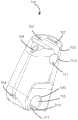
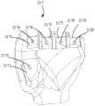
参阅图2至图27,在本申请的一些实施例中,所述机器人设备200包括机械臂210和第二处理器220。2 to 27 , in some embodiments of the present application, the
在一些实施例中,所述机械臂210包括手指部分211、手掌部分213、及手腕部分215。所述手指部分211包括第一组件300、第二组件400、第三组件500、第四组件600、及第五组件700。所述手腕部分215包括前手腕2151和后手腕2152。所述前手腕2151和后手腕2152均与手掌部分213的端部连接。所述前手腕2151和后手腕2152围合形成一容纳腔2153,所述运动控制机构212容纳于所述容纳腔2153。In some embodiments, the robot arm 210 includes a finger portion 211, a palm portion 213, and a
所述前手腕2151凸设有至少一凸起2154,所述后手腕2152开设有至少一凹槽2155,所述凸起2154容纳于凹槽2155。The
在一些实施例中,所述人机交互设备110的手套套设于所述机械臂210的手指部分211、或套设于所述机械臂210的手指部分211和手掌部分213、或套设于所述机械臂210的手指部分211、手掌部分213、及手腕部分215。In some embodiments, the glove of the human-
在一些实施例中,所述机械臂210可包括用于控制机械臂210的部件运动的运动控制机构212。所述运动控制机构212可包括用于与第二处理器220通信连接的多个电动机2122、受电动机2122驱动的多个摇动臂2121、支撑电动机2122的多个支撑座2123、及多个牵引线(未图示)。In some embodiments, the robot 210 may include a
在一些实施例中,所述第二处理器220可产生信号以操作运动控制机构212,使得运动控制机构212可以单独地控制机械臂210的一个或多个手指运动。In some embodiments, the
可以理解的,所述电动机2122、摇动臂2121、支撑座2123及牵引线的数量均为五个,分别对应第一组件300、第二组件400、第三组件500、第四组件600及第五组件700。在电动机2122、摇动臂2121、及牵引线的作用下,第一组件300、第二组件400、第三组件500、第四组件600及第五组件700可进行相应地运动。It can be understood that the number of the
在一些实施例中,所述第二处理器220可产生信号以操作一个或多个电动机2122带动一个或多个机械臂210运动,机械臂210通过对应的牵引线带动一个或多个组件运动。In some embodiments, the
可以理解的,所述运动控制机构212可以单独地控制机械臂210的一个或多个组件运动。It can be understood that the
参阅图2至图5,在一些实施例中,所述第一组件300类似人手拇指。第一组件300可包括类似于人手拇指的基片310和顶片330。在一些实施例中,可以使用3D打印技术来制造第一组件300。所述第一组件300的材质选自,但不限于,塑料、金属、陶瓷、金属合金、复合材料、橡胶等。Referring to FIGS. 2 to 5 , in some embodiments, the
所述基片310面向顶片330的表面开设有连接孔311和与所述连接孔311相连通的连接孔313,所述顶片330面向基片310的表面开设有连接孔331和与所述连接孔331相连通的连接孔333。The surface of the
在一些实施例中,所述连接孔311的尺寸大于连接孔313的尺寸,所述连接孔331的尺寸大于连接孔333的尺寸。In some embodiments, the size of the
在一些实施例中,所述连接孔311和连接孔331的竖截面大致为一圆形或椭圆形结构。所述连接孔313和连接孔333的竖截面大致为一长方形、正方形、或梯形结构。In some embodiments, the vertical cross-section of the
所述第一组件300可进一步包括连接器320,该连接器320用于连接基片310和顶片330。The
在一些实施例中,所述连接器320包括连接板321和分设于连接板321两端的二连接件323。所述二连接件323具有与连接孔311和连接孔331相匹配的形状,使得所述二连接件323可转动地容纳于连接孔311和连接孔331中。In some embodiments, the
在一些实施例中,所述连接孔311贯穿所述基片310的一端,从而形成开口3111,所述连接孔313也贯穿所述基片310的一端,从而形成与所述开口3111相连通的开口3131,以便于所述连接件323从该开口3111和开口3131进入该连接孔311中。In some embodiments, the
在一些实施例中,所述连接孔331贯穿所述顶片330的一端,从而形成开口3331,所述连接孔333也贯穿所述顶片330的一端,从而形成与所述开口3331相连通的开口3331,以便于另一连接件323从该开口3331和开口3331进入该连接孔331中。In some embodiments, the connecting
在一些实施例中,所述连接孔313和连接孔333的宽度略大于连接板321的厚度,以使连接器320可转动地与基片310和顶片330连接。In some embodiments, the width of the connection holes 313 and the connection holes 333 is slightly greater than the thickness of the
在一些实施例中,参图5,所述连接器320与基片310和顶片330连接后,所述连接板321可显露于基片310和顶片330之外,以使基片310和顶片330在转动过程中不会相互影响。In some embodiments, referring to FIG. 5 , after the
在一些实施例中,所述基片310还可包括标识符312。所述标识符312可用于识别部件以正确地组装各部件。In some embodiments, the
在一些实施例中,所述标识符312可以是开设于基片310的表面上的正方形切口。尽管标识符312是正方形的切口,本申请仍可采用其他辨认标志或技术。In some embodiments, the
在一些实施例中,所述标识符312开设于连接孔313的周缘。In some embodiments, the
在一些实施例中,所述顶片330还可包括标识符332。所述标识符332可用于识别部件以正确地组装各部件。In some embodiments, the
在一些实施例中,所述标识符332可以是开设于顶片330的表面上的正方形切口。尽管标识符332是正方形的切口,本申请仍可采用其他辨认标志或技术。In some embodiments, the
可以理解的,通过使用连接器320来连接基片310和顶片330,使得第一组件300保持至少三个自由度。It can be understood that by using the
所述基片310开设有通道,所述通道的入口318和出口319均面向手掌部分213。The
所述顶片330开设有通道,所述通道的入口338和出口339均面向手掌部分213。The
参照图6至图9,其示出了本申请一实施例的机器人设备200的第二组件400。在一些实施例中,所述第二组件400类似于人的食指。所述第二组件400可包括类似于人的食指的基片410、中间件430和顶片450。在一些实施例中,可以使用3D打印技术来制造第二组件400。所述第二组件400的材质包括,但不限于塑料,金属、陶瓷、金属合金、复合材料、橡胶等。Referring to FIGS. 6 to 9 , a second component 400 of a
所述基片410面向顶片450的表面开设有连接孔411和与所述连接孔411相连通的连接孔413。所述顶片450面向基片410的表面开设有连接孔451和与所述连接孔451相连通的连接孔453。所述中间件430面向基片410的表面形成有连接孔431和与所述连接孔431相连通的连接孔433。所述中间件面向顶片450的表面形成有连接孔435和与所述连接孔435相连通的连接孔437。The surface of the
在一些实施例中,所述连接孔411的尺寸大于连接孔413的尺寸,所述连接孔451的尺寸大于连接孔453的尺寸。所述连接孔431的尺寸大于连接孔433的尺寸。所述连接孔435的尺寸大于连接孔437的尺寸。In some embodiments, the size of the
在一些实施例中,所述连接孔411、连接孔451、连接孔431、及连接孔435的竖截面大致为一圆形或椭圆形结构。所述连接孔413、连接孔453、连接孔433、及连接孔437的竖截面大致为一长方形、正方形、或梯形结构。In some embodiments, the vertical cross-sections of the connection holes 411, 451, 431, and 435 are substantially circular or elliptical structures. The vertical cross-sections of the connection holes 413, 453, 433, and 437 are substantially rectangular, square, or trapezoidal structures.
参图5,所述第二组件400可以进一步包括用于连接基片410和中间件430的连接件320、以及用于连接中间件430和顶片450的连接件320。5 , the second component 400 may further include a
在一些实施例中,所述二连接件323具有与连接孔411和连接孔431相匹配的形状,使得所述二连接件323可转动地容纳于连接孔411和连接孔431中。In some embodiments, the two connecting
在一些实施例中,所述连接孔411贯穿所述基片410的一端,从而形成开口4111,所述连接孔413也贯穿所述基片410的一端,从而形成与所述开口4111相连通的开口4131,以便于所述连接件323从该开口4111和开口4131进入该连接孔411中。In some embodiments, the connecting
在一些实施例中,所述连接孔431贯穿所述中间件430的一端,从而形成开口4311,所述连接孔433也贯穿所述中间件430的一端,从而形成与所述开口4311相连通的开口4331,以便于另一连接件323从该开口4311和开口4331进入该连接孔431中。In some embodiments, the connecting
在一些实施例中,所述连接孔413和连接孔433的宽度略大于连接板321的厚度,以使连接器320可转动地与基片410和中间件430连接。In some embodiments, the width of the
在一些实施例中,所述连接器320与基片410和中间件430连接后,所述连接板321可显露于基片410和中间件430之外,以使基片410和中间件430在转动过程中不会相互影响。In some embodiments, after the
在一些实施例中,所述二连接件323具有与连接孔435和连接孔451相匹配的形状,使得所述二连接件323可转动地容纳于连接孔435和连接孔451中。In some embodiments, the two connecting
在一些实施例中,所述连接孔435贯穿所述中间件430的另一端,从而形成开口4351,所述连接孔435也贯穿所述中间件430的另一端,从而形成与所述开口4351相连通的开口4353,以便于所述连接件323从该开口4351和开口4353进入该连接孔435中。In some embodiments, the connecting
在一些实施例中,所述连接孔451贯穿所述顶片450的一端,从而形成开口4511,所述连接孔451也贯穿所述顶片450的一端,从而形成与所述开口4511相连通的开口4513,以便于连接件323从该开口4511和开口4513进入该连接孔451中。In some embodiments, the connecting
在一些实施例中,所述连接孔437和连接孔453的宽度略大于连接板321的厚度,以使连接器320可转动地与顶片450和中间件430连接。In some embodiments, the width of the
在一些实施例中,所述连接器320与顶片450和中间件430连接后,所述连接板321可显露于顶片450和中间件430之外,以使顶片450和中间件430在转动过程中不会相互影响。In some embodiments, after the
在一些实施例中,所述基片410可包括标识符412。所述标识符412可以用于识别元件,以利于组件的正确组装。In some embodiments, the
在一些实施例中,标识符412可为形成于基片410的表面上两个正方形切口。尽管标识符412为两个正方形切口,但是本申请还可以采用其他识别标记或技术。In some embodiments, the
在一些实施例中,中间件430可包括识别器432,该识别器432用于将中间件430和机械臂210的其他与中间件430类似的部件进行识别区分,从而有助于准确地组装。In some embodiments, the
在一些实施例中,所述顶片450可包括标识符452。所述标识符452可以用于识别元件,以利于组件的正确组装。In some embodiments, the
在一些实施例中,标识符452可为形成于顶片450的表面上两个正方形切口。尽管标识符452为两个正方形切口,但是本申请还可以采用其他识别标记或技术。In some embodiments, the
在一些实施例中,可以使用3D打印技术来制造基片410、连接件320、中间件430、连接件320和顶片450。In some embodiments, the
所述基片410开设有通道,所述通道的入口418和出口419均面向手掌部分213。开设有The
所述中间件430开设有通道,所述通道的入口438和出口439均面向手掌部分213。The
所述顶片450开设有通道,所述通道的入口458和出口459均面向手掌部分213。The
参阅图11至图14,其示出了本申请的一实施例的机械臂210的第三组件500。在一些实施例中,所述第三组件500类似于人手的中指。所述第三组件500可包括类似于人的中指的基片510、中间件530和顶片550。在一些实施例中,可以使用3D打印技术来制造第三组件500。所述第三组件500的材质可包括,但不限于,塑料、金属、陶瓷、金属合金、复合材料、橡胶等。Referring to FIGS. 11 to 14 , a third component 500 of the robot arm 210 of an embodiment of the present application is shown. In some embodiments, the third component 500 is similar to the middle finger of a human hand. The third component 500 may include a
所述基片510面向顶片550的表面开设有连接孔511和与所述连接孔511相连通的连接孔513。所述顶片550面向基片510的表面开设有连接孔551和与所述连接孔551相连通的连接孔553。所述中间件530面向基片510的表面形成有连接孔531和与所述连接孔531相连通的连接孔533。所述中间件530面向顶片550的表面形成有连接孔535和与所述连接孔535相连通的连接孔537。The surface of the
在一些实施例中,所述连接孔511的尺寸大于连接孔513的尺寸,所述连接孔551的尺寸大于连接孔553的尺寸。所述连接孔531的尺寸大于连接孔533的尺寸。所述连接孔535的尺寸大于连接孔537的尺寸。In some embodiments, the size of the
在一些实施例中,所述连接孔511、连接孔551、连接孔531、及连接孔535的竖截面大致为一圆形或椭圆形结构。所述连接孔513、连接孔553、连接孔533、及连接孔537的竖截面大致为一长方形、正方形、或梯形结构。In some embodiments, the vertical cross-sections of the connection holes 511, 551, 531, and 535 are substantially circular or elliptical structures. The vertical cross-sections of the connection holes 513, 553, 533, and 537 are substantially rectangular, square, or trapezoidal structures.
参图5,所述第三组件500可以进一步包括用于连接基片510和中间件530的连接器320、及用于连接中间件530和顶片550的连接器320。5 , the third component 500 may further include a
在一些实施例中,所述连接器320包括连接板321和分设于连接板321两端的二连接件323。所述二连接件323具有与连接孔511和连接孔531相匹配的形状,使得所述二连接件323可转动地容纳于连接孔511和连接孔531中。In some embodiments, the
在一些实施例中,所述连接孔511贯穿所述基片510的一端,从而形成开口5111,所述连接孔513也贯穿所述基片510的一端,从而形成与所述开口5111相连通的开口5131,以便于所述连接件323从该开口5111和开口5131进入该连接孔511中。In some embodiments, the
在一些实施例中,所述连接孔531贯穿所述中间件530的一端,从而形成开口5311,所述连接孔533也贯穿所述中间件530的一端,从而形成与所述开口5311相连通的开口5331,以便于另一连接件323从该开口5311和开口5331进入该连接孔531中。In some embodiments, the connecting
在一些实施例中,所述连接孔513和连接孔533的宽度略大于连接板321的厚度,以使连接器320可转动地与基片510和中间件530连接。In some embodiments, the width of the
在一些实施例中,所述连接器320与基片510和中间件530连接后,所述连接板321可显露于基片510和中间件530之外,以使基片510和中间件530在转动过程中不会相互影响。In some embodiments, after the
在一些实施例中,所述二连接件323具有与连接孔535和连接孔551相匹配的形状,使得所述二连接件323可转动地容纳于连接孔535和连接孔551中。In some embodiments, the two connecting
在一些实施例中,所述连接孔535贯穿所述中间件530的另一端,从而形成开口5351,所述连接孔537也贯穿所述中间件530的另一端,从而形成与所述开口5371相连通的开口5353,以便于所述连接件323从该开口5351和开口5371进入该连接孔535中。In some embodiments, the connecting
在一些实施例中,所述连接孔551贯穿所述顶片550的一端,从而形成开口5511,所述连接孔553也贯穿所述顶片550的一端,从而形成与所述开口5511相连通的开口5531,以便于连接件323从该开口5511和开口5531进入该连接孔551中。In some embodiments, the connecting
在一些实施例中,所述连接孔537和连接孔553的宽度略大于连接板551的厚度,以使连接器320可转动地与顶片550和中间件530连接。In some embodiments, the width of the
在一些实施例中,所述连接器320与顶片550和中间件530连接后,所述连接板551可显露于顶片550和中间件530之外,以使顶片550和中间件530在转动过程中不会相互影响。In some embodiments, after the
在一些实施例中,所述基片510可包括标识符512。所述标识符512可以用于识别部件,以正确地安装各部件。In some embodiments, the
在一些实施例中,所述标识符512可为形成于基片510的表面上三个正方形切口。尽管标识符512包括三个正方形切口,但是本申请仍可以采用其他识别标记或技术。In some embodiments, the
在一些实施例中,所述中间件530可包括识别器532,该识别器532用于将中间件530和机械臂210的其他与中间件530相似的部件进行识别并区别,从而有助于准确地组装。In some embodiments, the
在一些实施例中,所述顶片550可包括标识符552。所述标识符552可以用于识别部件,以正确地安装各部件。In some embodiments, the
在一些实施例中,所述标识符552可为形成于顶片550的表面上三个正方形切口。尽管标识符552包括三个正方形切口,但是本申请仍可以采用其他识别标记或技术。In some embodiments, the
在一些实施例中,可以使用3D打印技术来制造基件510、连接件320、中间件530、连接件320和顶片550。In some embodiments, the
所述基片510开设有通道,所述通道的入口518和出口519均面向手掌部分213。开设有The
所述中间件530开设有通道,所述通道的入口538和出口539均面向手掌部分213。The
所述顶片550开设有通道,所述通道的入口558和出口559均面向手掌部分213。The
参照图15-18,其示出了本申请的一实施例的机械臂的第四组件600。在一些实施例中,所述第四组件600类似于人的无名指。所述第四组件600可包括类似于人的食指的基片610、中间件630和顶片650。在一些实施例中,可以使用3D打印技术来制造第四组件600。所述第四组件600的材质可包括,但不限于,塑料、金属、陶瓷、金属合金、复合材料、橡胶等。Referring to FIGS. 15-18 , a fourth component 600 of a robotic arm of an embodiment of the present application is shown. In some embodiments, the fourth component 600 is similar to a human ring finger. The fourth component 600 may include a
所述基片610面向顶片650的表面开设有连接孔611和与所述连接孔611相连通的连接孔613。所述顶片650面向基片610的表面开设有连接孔651和与所述连接孔651相连通的连接孔653。所述中间件630面向基片610的表面形成有连接孔631和与所述连接孔631相连通的连接孔633。所述中间件630面向顶片650的表面形成有连接孔635和与所述连接孔635相连通的连接孔637。The surface of the
在一些实施例中,所述连接孔611的尺寸大于连接孔613的尺寸,所述连接孔651的尺寸大于连接孔653的尺寸。所述连接孔631的尺寸大于连接孔633的尺寸。所述连接孔635的尺寸大于连接孔637的尺寸。In some embodiments, the size of the
在一些实施例中,所述连接孔611、连接孔651、连接孔631、及连接孔635的竖截面大致为一圆形或椭圆形结构。所述连接孔613、连接孔653、连接孔633、及连接孔637的竖截面大致为一长方形、正方形、或梯形结构。In some embodiments, the vertical cross-sections of the connection holes 611, 651, 631, and 635 are substantially circular or elliptical structures. The vertical cross-sections of the connection holes 613, 653, 633, and 637 are substantially rectangular, square, or trapezoidal structures.
如图5中所示,所述第四组件600可以进一步包括用于连接基片610和中间件630的连接件320,以及用于连接中间件630和顶件650的连接件320。As shown in FIG. 5 , the fourth component 600 may further include a
在一些实施例中,所述二连接件323具有与连接孔611和连接孔631相匹配的形状,使得所述二连接件323可转动地容纳于连接孔611和连接孔631中。In some embodiments, the two connecting
在一些实施例中,所述连接孔611贯穿所述基片610的一端,从而形成开口6111,所述连接孔613也贯穿所述基片610的一端,从而形成与所述开口6111相连通的开口6131,以便于所述连接件323从该开口6111和开口6131进入该连接孔611中。In some embodiments, the
在一些实施例中,所述连接孔631贯穿所述中间件630的一端,从而形成开口6311,所述连接孔633也贯穿所述中间件630的一端,从而形成与所述开口6311相连通的开口6331,以便于另一连接件323从该开口6311和开口6331进入该连接孔631中。In some embodiments, the connecting
在一些实施例中,所述连接孔613和连接孔633的宽度略大于连接板321的厚度,以使连接器320可转动地与基片610和中间件630连接。In some embodiments, the width of the
在一些实施例中,所述连接器320与基片610和中间件630连接后,所述连接板321可显露于基片610和中间件630之外,以使基片610和中间件630在转动过程中不会相互影响。In some embodiments, after the
在一些实施例中,所述二连接件323具有与连接孔635和连接孔651相匹配的形状,使得所述二连接件323可转动地容纳于连接孔635和连接孔651中。In some embodiments, the two connecting
在一些实施例中,所述连接孔635贯穿所述中间件630的另一端,从而形成开口6351,所述连接孔637也贯穿所述中间件630的另一端,从而形成与所述开口6371相连通的开口6353,以便于所述连接件323从该开口6351和开口6371进入该连接孔635中。In some embodiments, the connecting
在一些实施例中,所述连接孔651贯穿所述顶片650的一端,从而形成开口6611,所述连接孔653也贯穿所述顶片650的一端,从而形成与所述开口6611相连通的开口6631,以便于连接件323从该开口6611和开口6631进入该连接孔651中。In some embodiments, the connecting hole 651 passes through one end of the
在一些实施例中,所述连接孔637和连接孔653的宽度略大于连接板651的厚度,以使连接器320可转动地与顶片650和中间件630连接。In some embodiments, the width of the
在一些实施例中,所述连接器320与顶片650和中间件630连接后,所述连接板651可显露于顶片650和中间件630之外,以使顶片650和中间件630在转动过程中不会相互影响。In some embodiments, after the
在一些实施例中,所述基片610可包括标识符612。所述标识符612可以用于识别部件,以利于部件的正确组装。In some embodiments, the
在一些实施例中,所述标识符612可为形成于基片610的表面上的四个正方形切口。尽管标识符612包括四个正方形切口,但是本申请仍可以采用其他识别标记或技术。In some embodiments, the
在一些实施例中,所述中间件630可形成有识别器632,该识别器632用于将中间件630和机械臂210的其他与中间件630相似的部件进行识别并区别,从而有助于准确地组装。In some embodiments, the
在一些实施例中,所述顶片650可包括标识符652。所述标识符652可以用于识别部件,以利于部件的正确组装。In some embodiments, the
在一些实施例中,所述标识符652可为形成于顶片650的表面上的四个正方形切口。尽管标识符652包括四个正方形切口,但是本申请仍可以采用其他识别标记或技术。In some embodiments, the identifier 652 may be four square cutouts formed on the surface of the
在一些实施例中,可以使用3D打印技术来制造基片610、连接件320、中间件630、连接件320和顶片650。In some embodiments, the
所述基片610开设有通道,所述通道的入口618和出口619均面向手掌部分213。开设有The
所述中间件630开设有通道,所述通道的入口638和出口639均面向手掌部分213。The
所述顶片650开设有通道,所述通道的入口658和出口659均面向手掌部分213。The
参照图17至图22,其示出了本申请一实施例的机械臂210的第五组件700。在一些实施例中,所述第五组件700类似于人手的小指。所述第五组件700可包括类似于人的食指的基片710、中间件730和顶片750。在一些实施例中,可以使用3D打印技术来制造第五组件700。所述第五组件700的材质可包括,但不限于,塑料、金属、陶瓷、金属合金、复合材料、橡胶等。Referring to FIGS. 17 to 22 , the
所述基片710面向顶片750的表面开设有连接孔711和与所述连接孔711相连通的连接孔713。所述顶片750面向基片710的表面开设有连接孔751和与所述连接孔751相连通的连接孔753。所述中间件730面向基片710的表面形成有连接孔731和与所述连接孔731相连通的连接孔733。所述中间件730面向顶片750的表面形成有连接孔735和与所述连接孔735相连通的连接孔737。The surface of the
在一些实施例中,所述连接孔711的尺寸大于连接孔713的尺寸,所述连接孔751的尺寸大于连接孔753的尺寸。所述连接孔731的尺寸大于连接孔733的尺寸。所述连接孔735的尺寸大于连接孔737的尺寸。In some embodiments, the size of the
在一些实施例中,所述连接孔711、连接孔751、连接孔731、及连接孔735的竖截面大致为一圆形或椭圆形结构。所述连接孔713、连接孔753、连接孔733、及连接孔737的竖截面大致为一长方形、正方形、或梯形结构。In some embodiments, the vertical cross-sections of the connection holes 711, 751, 731, and 735 are substantially circular or elliptical structures. The vertical cross-sections of the connection holes 713, 753, 733, and 737 are substantially rectangular, square, or trapezoidal structures.
如图5所示,所述第五组件700可以进一步包括用于连接基片710和中间件730的连接器320、以及用于连接中间件730和顶片750的连接器320。As shown in FIG. 5 , the
在一些实施例中,所述连接器320包括连接板321和分设于连接板321两端的二连接件323。所述二连接件323具有与连接孔711和连接孔731相匹配的形状,使得所述二连接件323可转动地容纳于连接孔711和连接孔731中。In some embodiments, the
在一些实施例中,所述连接孔711贯穿所述基片710的一端,从而形成开口7111,所述连接孔713也贯穿所述基片710的一端,从而形成与所述开口7111相连通的开口7131,以便于所述连接件323从该开口7111和开口7131进入该连接孔711中。In some embodiments, the
在一些实施例中,所述连接孔731贯穿所述中间件730的一端,从而形成开口7311,所述连接孔733也贯穿所述中间件730的一端,从而形成与所述开口7311相连通的开口7331,以便于另一连接件323从该开口7311和开口7331进入该连接孔731中。In some embodiments, the connecting
在一些实施例中,所述连接孔713和连接孔733的宽度略大于连接板321的厚度,以使连接器320可转动地与基片710和中间件730连接。In some embodiments, the width of the connection holes 713 and 733 is slightly greater than the thickness of the
在一些实施例中,所述连接器320与基片710和中间件730连接后,所述连接板321可显露于基片710和中间件730之外,以使基片710和中间件730在转动过程中不会相互影响。In some embodiments, after the
在一些实施例中,所述二连接件323具有与连接孔735和连接孔751相匹配的形状,使得所述二连接件323可转动地容纳于连接孔735和连接孔751中。In some embodiments, the two connecting
在一些实施例中,所述连接孔735贯穿所述中间件730的另一端,从而形成开口7351,所述连接孔737也贯穿所述中间件730的另一端,从而形成与所述开口7371相连通的开口7353,以便于所述连接件323从该开口7351和开口7371进入该连接孔735中。In some embodiments, the connecting
在一些实施例中,所述连接孔751贯穿所述顶片750的一端,从而形成开口7711,所述连接孔753也贯穿所述顶片750的一端,从而形成与所述开口7711相连通的开口7731,以便于连接件323从该开口7711和开口7731进入该连接孔751中。In some embodiments, the connecting
在一些实施例中,所述连接孔737和连接孔753的宽度略大于连接板751的厚度,以使连接器320可转动地与顶片750和中间件730连接。In some embodiments, the width of the
在一些实施例中,所述连接器320与顶片750和中间件730连接后,所述连接板751可显露于顶片750和中间件730之外,以使顶片750和中间件730在转动过程中不会相互影响。In some embodiments, after the
在一些实施例中,所述基片710可包括标识符712。识别器712可以用于识别部件,以利于组件的正确组装。In some embodiments, the
在一些实施例中,所述标识符712可为形成于基片710的表面上的五个正方形切口。尽管标识符712包括五个正方形切口,但是本申请仍可以采用其他识别标记或技术。In some embodiments, the
在一些实施例中,所述中间件730可包括识别器732,该识别器732用于将中间件730与与中间件730相似的机械臂210的部件进行识别并区分,从而有助于准确地组装。In some embodiments, the
在一些实施例中,所述顶片750可包括标识符752。识别器752可以用于识别部件,以利于组件的正确组装。In some embodiments, the
在一些实施例中,所述标识符752可为形成于顶片750的表面上的五个正方形切口。尽管标识符752包括五个正方形切口,但是本申请仍可以采用其他识别标记或技术。In some embodiments, the
在一些实施例中,可以使用3D打印技术来制造基片710,连接器320,中间件730,连接器320和顶片750。In some embodiments, the
所述基片710开设有通道,所述通道的入口718和出口719均面向手掌部分213。开设有The
所述中间件730开设有通道,所述通道的入口738和出口739均面向手掌部分213。The
所述顶片750开设有通道,所述通道的入口758和出口759均面向手掌部分213。The
所述手掌部分213包括前手掌217和后手掌218。所述前手掌217对应第一组件300的区域开设有连接槽2171、对应第二组件400的连接槽2173、对应第三组件500的连接槽2175、对应第四组件600的连接槽2177、对应第五组件700的连接槽2179。The palm portion 213 includes a
在一些实施例中,所述连接槽2171开设于手掌部分213的对应第一组件300的关节上。所述第一组件300安装于位于大拇指的关节区域的连接槽2171中。In some embodiments, the
所述连接槽2171的周缘开设有通孔2172,所述通孔2172与前手掌217和后手掌2132围合形状的容置空间和前手腕2151和后手腕2152围合形成的容纳腔2153连通。A through
所述连接槽2171的尺寸与连接件323的尺寸相匹配。The size of the connecting
在一些实施例中,所述连接槽2173开设于手掌部分213的对应第二组件400的关节上。所述第二组件400安装于位于大拇指的关节区域的连接槽2173中。In some embodiments, the
所述连接槽2173的周缘开设有通孔2174,所述通孔2174与前手掌217和后手掌2132围合形状的容置空间和前手腕2151和后手腕2152围合形成的容纳腔2153连通。A through
在一些实施例中,所述连接槽2175开设于手掌部分213的对应第三组件500的关节上。所述第三组件500安装于位于大拇指的关节区域的连接槽2175中。In some embodiments, the
所述连接槽2175的周缘开设有通孔2176,所述通孔2176与前手掌217和后手掌2132围合形状的容置空间和前手腕2151和后手腕2152围合形成的容纳腔2153连通。A through
在一些实施例中,所述连接槽2177开设于手掌部分213的对应第四组件600的关节上。所述第四组件600安装于位于大拇指的关节区域的连接槽217中。In some embodiments, the
所述连接槽2177的周缘开设有通孔2178,所述通孔2178与前手掌217和后手掌2132围合形状的容置空间和前手腕2151和后手腕2152围合形成的容纳腔2153连通。A through
在一些实施例中,所述连接槽2179开设于手掌部分213的对应第五组件700的关节上。所述第五组件700安装于位于大拇指的关节区域的连接槽2179中。In some embodiments, the
所述连接槽2179的周缘开设有通孔2120,所述通孔2120与前手掌217和后手掌2132围合形状的容置空间和前手腕2151和后手腕2152围合形成的容纳腔2153连通。A through
所述前手掌217背向第一组件300的表面于对应第二组件400的区域开设有子凹槽2124、于对应第三组件500的区域开设有子凹槽2125、于对应第四组件600的区域开设有子凹槽2126、于对应第五组件700的区域开设有子凹槽2127。The surface of the
所述后手掌2132面向前手掌217的表面于对应第二组件400的区域开设有子凹槽2181、于对应第三组件500的区域开设有子凹槽2182、于对应第四组件600的区域开设有子凹槽2183、于对应第五组件700的区域开设有子凹槽2184。The surface of the rear palm 2132 facing the
所述子凹槽2124与子凹槽2181共同围合形成容纳与第二组件400的连接件323的凹槽。所述凹槽具有与连接件323相匹配的尺寸,所述连接件323可转动地容纳于凹槽中。The sub-groove 2124 and the sub-groove 2181 together enclose a groove for accommodating the connecting
子凹槽2125与子凹槽2182共同围合形成容纳与第三组件500的连接件323的凹槽。所述凹槽具有与连接件323相匹配的尺寸,所述连接件323可转动地容纳于凹槽中。The sub-groove 2125 and the sub-groove 2182 are enclosed together to form a groove for accommodating the connecting
子凹槽2126与子凹槽2183共同围合形成容纳与第四组件600的连接件323的凹槽。所述凹槽具有与连接件323相匹配的尺寸,所述连接件323可转动地容纳于凹槽中。The sub-groove 2126 and the sub-groove 2183 are enclosed together to form a groove for accommodating the connecting
子凹槽2127与子凹槽2184共同围合形成容纳与第五组件700的连接件323的凹槽。所述凹槽具有与连接件323相匹配的尺寸,所述连接件323可转动地容纳于凹槽中。The sub-groove 2127 and the sub-groove 2184 are enclosed together to form a groove for accommodating the connecting
所述第一组件300的基片310面向手掌部分213的表面开设有连接孔315和与所述连接孔315相连通的连接孔317。在一些实施例中,所述连接孔315的尺寸大于连接孔317的尺寸。所述连接孔315的竖截面的尺寸大致为圆形或椭圆形,所述连接孔317的竖截面的尺寸大致为长方形、正方形或梯形。The surface of the
在一些实施例中,所述基片310的连接孔315和连接孔317均贯穿基片310远离第二组件400的表面,从而形成开孔3151和开孔3171。In some embodiments, the connection holes 315 and the connection holes 317 of the
所述第二组件400的基片410面向手掌部分213的表面开设有连接孔415和与所述连接孔415相连通的连接孔417。在一些实施例中,所述连接孔415的尺寸大于连接孔417的尺寸。所述连接孔415的竖截面的尺寸大致为圆形或椭圆形,所述连接孔417的竖截面的尺寸大致为长方形、正方形或梯形。The surface of the
所述第三组件500的基片510面向手掌部分213的表面开设有连接孔515和与所述连接孔515相连通的连接孔517。在一些实施例中,所述连接孔515的尺寸大于连接孔517的尺寸。所述连接孔515的竖截面的尺寸大致为圆形或椭圆形,所述连接孔517的竖截面的尺寸大致为长方形、正方形或梯形。The surface of the
所述第四组件600的基片610面向手掌部分213的表面开设有连接孔615和与所述连接孔615相连通的连接孔617。在一些实施例中,所述连接孔615的尺寸大于连接孔617的尺寸。所述连接孔615的竖截面的尺寸大致为圆形或椭圆形,所述连接孔617的竖截面的尺寸大致为长方形、正方形或梯形。The surface of the
所述第五组件700的基片710面向手掌部分213的表面开设有连接孔715和与所述连接孔715相连通的连接孔717。在一些实施例中,所述连接孔715的尺寸大于连接孔717的尺寸。所述连接孔715的竖截面的尺寸大致为圆形或椭圆形,所述连接孔717的竖截面的尺寸大致为长方形、正方形或梯形。The surface of the
所述手掌部分213还包括若干连接器320。每一连接器320均包括连接板321和分设于连接板321两端的二连接件323。所述连接件323的竖截面的尺寸大致为圆形或椭圆形。The palm portion 213 further includes a plurality of
在一些实施例中,所述连接器320的个数为4个。In some embodiments, the number of the
一连接器320的一连接件323可转动地容纳于子凹槽2124与子凹槽2181共同围合的凹槽中,另一连接件323可转动地容纳于连接孔415。A connecting
一连接器320的一连接件323可转动地容纳于子凹槽2125与子凹槽2182共同围合的凹槽中,另一连接件323可转动地容纳于连接孔515。A connecting
一连接器320的一连接件323可转动地容纳于子凹槽2126与子凹槽2183共同围合形成的凹槽中,另一连接件323可转动地容纳于连接孔615。A connecting
一连接器320的一连接件323可转动地容纳于子凹槽2127与子凹槽2184共同围合形成的凹槽中,另一连接件323可转动地容纳于连接孔715。A connecting
在一些实施例中,对应所述第一组件300的连接槽2171的周缘设有标识符2185、对应所述第二组件400的连接槽2173的周缘设有标识符2186、对应所述第三组件500的连接槽2175的周缘设有标识符2187、对应所述第四组件600的连接槽2177的周缘设有标识符2188、对应所述第五组件700的连接槽2179的周缘设有标识符2189。以方便将组件组装到手掌部分213的合适的区域。In some embodiments, an identifier 2185 is provided on the periphery of the
可以理解的,设于所述连接槽2171的周缘的标识符2185可以是开设于连接槽2171的周缘的正方形切口。尽管标识符2185是正方形的切口,本申请仍可采用其他辨认标志或技术。It can be understood that the identifier 2185 provided on the periphery of the
可以理解的,设于所述连接槽2173的周缘的标识符2186可以是开设于连接槽2173的周缘的正方形切口。尽管标识符2186是正方形的切口,本申请仍可采用其他辨认标志或技术。It can be understood that the identifier 2186 provided on the periphery of the
可以理解的,设于所述连接槽2175的周缘的标识符2187可以是开设于连接槽2175的周缘的正方形切口。尽管标识符2187是正方形的切口,本申请仍可采用其他辨认标志或技术。It can be understood that the identifier 2187 provided on the periphery of the
可以理解的,设于所述连接槽2177的周缘的标识符2188可以是开设于连接槽2177的周缘的正方形切口。尽管标识符2188是正方形的切口,本申请仍可采用其他辨认标志或技术。It can be understood that the identifier 2188 provided on the periphery of the
可以理解的,设于所述连接槽2179的周缘的标识符2189可以是开设于连接槽2179的周缘的正方形切口。尽管标识符2189是正方形的切口,本申请仍可采用其他辨认标志或技术。It can be understood that the identifier 2189 provided on the periphery of the
在一些实施例中,本申请可通过专有的AI算法,使得机器人设备200可以学会理解每个截肢者的所需手势。该机器人设备的操纵系统会随着个人使用而不断适应和改进,使得该机器人的操纵系统具有强大的功能。具体地,所述机器人设备200可以分析肌肉发出的电信号,从而使其智能地适应和学习每个截肢者所需的手势,从而以前所未有的精度模仿人手的功能。In some embodiments, the present application can use a proprietary AI algorithm to enable the
上述过程创造了前所未有的自然体验,并使假肢成为用户的天生延伸,使得该机器人的操纵系统具有较强的可用性。The above process creates an unprecedented natural experience and makes the prosthesis a natural extension of the user, making the robot's manipulation system highly usable.
所述机器人设备200的结构简单,使得其成本较低。The
学生可以构建并进行远程控制机器人设备200。这是学习机器人技术和假肢的一个很好的切入点。最重要的是,该机器人设备200可以重新构建和拆开,以用于多种用途。从而为所有年龄段的学生提供了完全可定制的学习体验。基于我们实际假肢使用的相同技术,我们的机器人设备200是希望学习机器人技术,假肢和编程的学生的绝佳入门点。Students can build and remotely control the
学生可探索机械、电气和计算机工程的基础知识,使用具有遥控功能的红外传感器、程序特定的手势和代码微控制器来操作该机器人设备200的运动控制机构等。Students can explore the basics of mechanical, electrical, and computer engineering, use infrared sensors with remote control capabilities, program specific gestures and code microcontrollers to operate the motion control mechanism of the
作为附加选项,可于该机器人设备200上套设一个定制手套,该手套使用柔性传感器读取每个类似人手指的组件的实时位置,使学生能够精确控制刚构建的机器人设备200的运动。As an additional option, a custom glove can be put over the
参阅图28,其示出了本申请的一实施例的机械臂的组装方法1000。如图8所示,组装后的组件400、500、600和700可以使用若干连接器320与机械臂210的手掌相连接。Referring to FIG. 28 , a
所述组装方法具体包括:The assembly method specifically comprises:
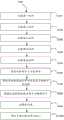
S100,组装第一组件300。S100, assembling the
所述S100包括:提供基片310、顶片330及连接器320;将连接器320的其中一连接件323穿过该开口3111和开口3131,以可转动地容纳于进入该基片310的连接孔311中;将连接器320的另一连接件323穿过该开口3331和开口3331,以可转动地容纳于进入该顶片330的连接孔331中,以将基片310和顶片330通过连接器320连接,获得第一组件300。The S100 includes: providing a
S200,组装第二组件400。S200, assembling the second component 400.
所述S200包括:提供基片410、二连接器320、中间件430、及顶片450;将一连接器320的一连接件323穿过该开口4111和开口4131,以可转动地容纳于进入该基片410的连接孔411中;将连接器320的另一连接件323穿过该开口4311和开口4331,进入该中间件430的连接孔431中;将另一连接器320的一连接件323穿过该开口4351和开口4353,进入该中间件430的连接孔435中;将该连接器320的另一连接件323穿过该开口4511和开口4513以可转动地容纳于进入该顶片450的连接孔451中,以将基片410、中间件430、顶片450通过二连接器320连接,获得第二组件400。The S200 includes: providing a
S300,组装第三组件500。S300, assembling the third component 500.
所述S300包括:提供基片510、二连接器320、中间件530、及顶片550;将一连接器320的一连接件323穿过该开口5111和开口5131,以可转动地容纳于进入该基片510的连接孔511中;将一连接器320的另一连接件323穿过该开口5311和开口5331,进入该中间件530的连接孔531中;将另一连接器320的一连接件323穿过该开口5351和开口5353,进入该中间件530的连接孔535中;将连接器320的另一连接件323穿过该开口5511和开口5513以可转动地容纳于进入该顶片550的连接孔551中,以将基片510、中间件530、顶片550通过二连接器320连接,获得第三组件500。The S300 includes: providing a
S400,组装第四组件600。S400, assembling the fourth component 600.
所述S300包括:提供基片610、二连接器320、中间件630、及顶片650;将一连接器320的一连接件323穿过该开口6111和开口6131,以可转动地容纳于进入该基片610的连接孔611中;将连接器320的另一连接件323穿过该开口6311和开口6331,进入该中间件630的连接孔631中;将另一连接器320的一连接件323穿过该开口6351和开口6353,进入该中间件630的连接孔635中;将另一连接器320的另一连接件323穿过该开口6511和开口6513以可转动地容纳于进入该顶片650的连接孔651中,以将基片610、中间件630、顶片650通过二连接器320连接,获得第四组件600。The S300 includes: providing a
S500,组装第五组件700。S500, assembling the
所述S300包括:提供基片710、二连接器320、中间件730、及顶片750;将一连接器320的一连接件323穿过该开口7111和开口7131,以可转动地容纳于进入该基片710的连接孔711中;将连接器320的另一连接件323穿过该开口7311和开口7331,进入该中间件730的连接孔731中;将另一连接器320的一连接件323穿过该开口7351和开口7353,进入该中间件730的连接孔735中;将连接器320的另一连接件323穿过该开口7511和开口7513以可转动地容纳于进入该顶片750的连接孔751中,以将基片710、中间件730、顶片750通过二连接器320连接,获得第五组件700,获得手指部分211。The S300 includes: providing a
S600,组装手指部分211于手掌部分213。S600 , assembling the finger portion 211 to the palm portion 213 .
所述S600包括:提供手掌部分213和若干连接器320;将一连接器320的一连接件323可转动地容纳于手掌部分213的连接槽2171,另一连接件323可转动地容纳于第一组件300的连接孔315,以将第一组件300与手掌部分213可转动地连接;将一连接器320的一连接件323可转动地容纳于手掌部分213的由子凹槽2124与子凹槽2181共同围合形成的凹槽,另一连接件323可转动地容纳于第二组件400的连接孔415,以将第二组件400与手掌部分213可转动地连接;将一连接器320的一连接件323可转动地容纳于手掌部分213的由子凹槽2125与子凹槽2182共同围合形成的凹槽,另一连接件323可转动地容纳于第三组件500的连接孔515,以将第三组件500与手掌部分213可转动地连接;将一连接器320的一连接件323可转动地容纳于手掌部分213的由子凹槽2126与子凹槽2183共同围合形成的凹槽,另一连接件323可转动地容纳于第四组件600的连接孔615,以将第四组件600与手掌部分213可转动地连接;将一连接器320的一连接件323可转动地容纳于手掌部分213的由子凹槽2127与子凹槽2184共同围合形成的凹槽,另一连接件323可转动地容纳于第五组件700的连接孔715,以将第五组件700与手掌部分213可转动地连接。The S600 includes: providing a palm portion 213 and a plurality of
在一些实施例中,所述基片310的连接孔315和连接孔317均贯穿基片310远离第二组件400的表面,从而形成开孔3151和开孔3171。所述连接器320的其中一连接件323可穿过开孔3151,连接器320的连接板321可穿过开孔3171,以将第一组件300与手掌部分213可转动地连接。In some embodiments, the
S700,将前手腕2151组装到手掌部分213远离手指部分211的端部。S700 , assembling the
在一些实施例中,所述手掌部分213远离手指部分211的端部设有若干安装孔,所述前手腕2151也对应设有若干安装孔,可通过连接件、安装孔之间的配合,将手掌部分213与前手腕2151连接。连接件可为螺丝等。In some embodiments, the palm portion 213 is provided with a plurality of mounting holes at the end away from the finger portion 211, and the
S800,提供运动控制机构212,将运动控制机构212安装于手腕部分2151中。S800 , providing a
在一些实施例中,所述运动控制机构212可包括伺服板。In some embodiments, the
在一些实施例中,所述前手腕2151上形成有支架(未图示),所述支架上开设有若干安装孔,如4个安装孔。所述运动控制机构212上也开设有若干安装孔,如4个安装孔。通过连接件,如螺丝等,穿过运动控制机构212上的安装孔和支架上的安装孔,以将运动控制机构212和前手腕2151连接。In some embodiments, a bracket (not shown) is formed on the
可以理解的,所述运动控制机构212上的伺服臂2121都指向上方,即朝向顶片的方向。It can be understood that the
S900,安装牵引线。S900, install the traction line.
所述S800包括:The S800 includes:
将一牵引线的第一端穿过前手掌217和后手掌2132围合形状的容置空间和前手腕2151和后手腕2152围合形成的容纳腔2153,从通孔2172和基片310的入口318进入通道的内部,再从基片310的出口319穿出通道,再通过顶片330的入口338进入通道的内部,再从顶片330的出口339穿出通道后,打结固定;将该牵引线的第二端与对应第一组件300的摇动臂连接;The first end of a traction line is passed through the accommodation space enclosed by the
将一牵引线的第一端穿过前手掌217和后手掌2132围合形状的容置空间和前手腕2151和后手腕2152围合形成的容纳腔2153,从通孔2174和基片410的入口418进入通道的内部,再从基片410的出口419穿出通道后,从中间件430的入口438进入通道的内部,再从中间件430的出口439穿出通道,再从顶片450的入口458进入通道的内部,再从顶片450的出口459穿出通道后,打结固定;将该牵引线的第二端与对应第二组件400的摇动臂连接;The first end of a traction line is passed through the accommodating space formed by the
将一牵引线的第一端穿过前手掌217和后手掌2132围合形状的容置空间和前手腕2151和后手腕2152围合形成的容纳腔2153,从通孔2176和基片510的入口518进入通道的内部,再从基片510的出口519穿出通道后,从中间件530的入口538进入通道的内部,再从中间件530的出口539穿出通道,再从顶片550的入口558进入通道的内部,再从顶片550的出口559穿出通道后,打结固定;将该牵引线的第二端与对应第三组件500的摇动臂连接;The first end of a traction line is passed through the accommodating space formed by the
将一牵引线的第一端穿过前手掌217和后手掌2132围合形状的容置空间和前手腕2151和后手腕2152围合形成的容纳腔2153,从通孔2178和基片610的入口618进入通道的内部,再从基片610的出口619穿出通道后,从中间件630的入口638进入通道的内部,再从中间件630的出口639穿出通道,再从顶片650的入口658进入通道的内部,再从顶片650的出口659穿出通道后,打结固定;将该牵引线的第二端与对应第四组件600的摇动臂连接;The first end of a traction line is passed through the accommodating space formed by the
将一牵引线的第一端穿过前手掌217和后手掌2132围合形状的容置空间和前手腕2151和后手腕2152围合形成的容纳腔2153,从通孔2120和基片710的入口718进入通道的内部,再从基片710的出口719穿出通道后,从中间件730的入口738进入通道的内部,再从中间件730的出口739穿出通道,再从顶片750的入口758进入通道的内部,再从顶片750的出口759穿出通道后,打结固定;将该牵引线的第二端与对应第五组件300的摇动臂连接。The first end of a traction line is passed through the accommodating space enclosed by the
S1000,将后手腕2152组装到前手腕2151上。S1000, assemble the
在一些实施例中,所述前手腕2151和后手腕2152共同形成有容纳腔2153,所述运动控制机构212容纳于所述容纳腔2153中。In some embodiments, the
可以理解的,打结时,可打两次结,以增加力量,确保所有的牵引线又紧又直。Understandably, when tying knots, you can tie two knots to increase strength and ensure that all traction lines are tight and straight.
在一些实施例中,还包括切除多余的牵引线的步骤。In some embodiments, the method further includes the step of cutting off excess traction wire.
在一些实施例中,把运动控制机构的线,即分别对应五个组件的线,放在一起,用胶带粘好。并将粘好的线引入第二控制器220中,与第二控制器220通信连接。In some embodiments, the wires of the motion control mechanism, that is, the wires corresponding to the five components, are put together and glued together with tape, and the glued wires are introduced into the
可以理解的,所述牵引线可为线或细绳。所述牵引线的材质包括,但不限于,尼龙、塑料、橡胶、金属等。It is understandable that the traction line can be a wire or a string. The material of the traction line includes, but is not limited to, nylon, plastic, rubber, metal, etc.
上述组装方法简单,且该机器人设备200具有可拆卸性。The above-mentioned assembling method is simple, and the
以上所述仅为本发明的优选实施例而已,并不用于限制本发明,对于本领域的技术人员来说,本发明可以有各种更改和变化。凡在本发明的精神和原则之内,所作的任何修改、等同替换、改进等,均应包含在本发明的保护范围之内。The above description is only a preferred embodiment of the present invention and is not intended to limit the present invention. For those skilled in the art, the present invention may have various modifications and variations. Any modification, equivalent replacement, improvement, etc. made within the spirit and principle of the present invention shall be included in the protection scope of the present invention.
Claims (7)
Translated fromChinesePriority Applications (1)
| Application Number | Priority Date | Filing Date | Title |
|---|---|---|---|
| US16/789,752US11612999B2 (en) | 2019-05-29 | 2020-02-13 | System and method for manipulating robotic device |
Applications Claiming Priority (2)
| Application Number | Priority Date | Filing Date | Title |
|---|---|---|---|
| US201962854314P | 2019-05-29 | 2019-05-29 | |
| US62/854,314 | 2019-05-29 |
Publications (2)
| Publication Number | Publication Date |
|---|---|
| CN110962146A CN110962146A (en) | 2020-04-07 |
| CN110962146Btrue CN110962146B (en) | 2023-05-09 |
Family
ID=70034153
Family Applications (1)
| Application Number | Title | Priority Date | Filing Date |
|---|---|---|---|
| CN201911278371.5AActiveCN110962146B (en) | 2019-05-29 | 2019-12-12 | System and method for manipulating a robotic device |
Country Status (2)
| Country | Link |
|---|---|
| US (1) | US11612999B2 (en) |
| CN (1) | CN110962146B (en) |
Family Cites Families (17)
| Publication number | Priority date | Publication date | Assignee | Title |
|---|---|---|---|---|
| US4972074A (en)* | 1989-04-10 | 1990-11-20 | Scott M. Wright | Optical attenuator movement detection system |
| CN103170960A (en)* | 2013-03-14 | 2013-06-26 | 吉林大学 | Human-imitation synchronous wireless control mechanical arm system |
| CN103677289A (en)* | 2013-12-09 | 2014-03-26 | 中国科学院深圳先进技术研究院 | Intelligent interactive glove and interactive method |
| US10518409B2 (en)* | 2014-09-02 | 2019-12-31 | Mark Oleynik | Robotic manipulation methods and systems for executing a domain-specific application in an instrumented environment with electronic minimanipulation libraries |
| US10055019B2 (en)* | 2015-05-20 | 2018-08-21 | Sony Interactive Entertainment Inc. | Electromagnet-laden glove for haptic pressure feedback |
| US10219919B2 (en)* | 2015-08-18 | 2019-03-05 | Yale University | Multi-grasp prosthetic hand |
| CN105677036B (en)* | 2016-01-29 | 2018-04-10 | 清华大学 | A kind of interactive data gloves |
| US20170249561A1 (en)* | 2016-02-29 | 2017-08-31 | GM Global Technology Operations LLC | Robot learning via human-demonstration of tasks with force and position objectives |
| CN105653044A (en)* | 2016-03-14 | 2016-06-08 | 北京诺亦腾科技有限公司 | Motion capture glove for virtual reality system and virtual reality system |
| US10737377B2 (en)* | 2016-03-15 | 2020-08-11 | Kindred Systems Inc. | Systems, devices, articles, and methods for robots in workplaces |
| CN206551039U (en)* | 2017-01-18 | 2017-10-13 | 西北工业大学 | A kind of remote operation line trailer-type machine hand |
| CA3071332A1 (en)* | 2017-07-25 | 2019-01-31 | Mbl Limited | Systems and methods for operations a robotic system and executing robotic interactions |
| CN107553499A (en)* | 2017-10-23 | 2018-01-09 | 上海交通大学 | Natural the gesture motion control system and method for a kind of Multi-shaft mechanical arm |
| CN108972494B (en)* | 2018-06-22 | 2020-09-22 | 华南理工大学 | Humanoid manipulator grabbing control system and data processing method thereof |
| US11341826B1 (en)* | 2018-08-21 | 2022-05-24 | Meta Platforms, Inc. | Apparatus, system, and method for robotic sensing for haptic feedback |
| CN109571513B (en)* | 2018-12-15 | 2023-11-24 | 华南理工大学 | Immersive mobile grabbing service robot system |
| CN109646156B (en)* | 2018-12-19 | 2021-02-12 | 南京航空航天大学 | Exoskeleton rehabilitation glove |
- 2019
- 2019-12-12CNCN201911278371.5Apatent/CN110962146B/enactiveActive
- 2020
- 2020-02-13USUS16/789,752patent/US11612999B2/enactiveActive
Also Published As
| Publication number | Publication date |
|---|---|
| US20200376649A1 (en) | 2020-12-03 |
| CN110962146A (en) | 2020-04-07 |
| US11612999B2 (en) | 2023-03-28 |
Similar Documents
| Publication | Publication Date | Title |
|---|---|---|
| US11772266B2 (en) | Systems, devices, articles, and methods for using trained robots | |
| Ho et al. | Virtual reality training for assembly of hybrid medical devices | |
| Zhai et al. | Quantifying coordination in multiple DOF movement and its application to evaluating 6 DOF input devices | |
| US20110148607A1 (en) | System,device and method for providing haptic technology | |
| Riley et al. | Enabling real-time full-body imitation: a natural way of transferring human movement to humanoids | |
| CA2882968A1 (en) | Facilitating generation of autonomous control information | |
| CN106371611A (en) | Piano playing teaching assistance device | |
| CN116301384A (en) | Correction method | |
| Alonso et al. | Exploiting virtual reality and the robot operating system to remote-control a humanoid robot | |
| CA3110725A1 (en) | Vibrotactile method, apparatus and system for training and practicing dental procedures | |
| CN110962146B (en) | System and method for manipulating a robotic device | |
| Wang et al. | Modelling of human haptic skill: A framework and preliminary results | |
| CN110363841B (en) | Hand motion tracking method in virtual driving environment | |
| CN108958479B (en) | Real-time interaction method of general 3D virtual scene based on data glove | |
| CN206209598U (en) | A kind of piano playing teaching auxiliary device | |
| Batik et al. | Shiftly: A Novel Origami Shape-Shifting Haptic Device for Virtual Reality | |
| West Jr | Towards a non-invasive measurement of human motion, force, and impedance during a complex physical-interaction task: wire-harnessing | |
| Krieger | A vr serious game framework for haptic performance evaluation | |
| Li et al. | Piano Beginner: A Glove-based Finger Training VR Application | |
| CN212032115U (en) | Virtual reality sensing equipment and virtual reality system | |
| CN114905514B (en) | Human skill learning method and system for outer limb grasping control | |
| CN118625931B (en) | Force feedback glove system for VR scene and construction method thereof | |
| CN111562846A (en) | Virtual reality sensing equipment and virtual reality system | |
| Kraal | An application of virtual reality to engineering design: synthesis of spherical mechanisms | |
| Mourad | Human interface and interaction in the WITS training system |
Legal Events
| Date | Code | Title | Description |
|---|---|---|---|
| PB01 | Publication | ||
| PB01 | Publication | ||
| SE01 | Entry into force of request for substantive examination | ||
| SE01 | Entry into force of request for substantive examination | ||
| GR01 | Patent grant | ||
| GR01 | Patent grant | ||
| TR01 | Transfer of patent right | ||
| TR01 | Transfer of patent right | Effective date of registration:20250829 Address after:311106 Zhejiang Province Hangzhou City Yuhang District Yuhang Street Wenyi West Road No. 1818-2 Building 1 Room 201-5 Patentee after:ZHEJIANG QIANGNAO TECHNOLOGY Co.,Ltd. Country or region after:China Address before:120 Beacon Street, Somerville, Ma Patentee before:Borrec Co.,Ltd. Country or region before:U.S.A. |