CN110943226B - Positive current collector, positive pole piece and electrochemical device - Google Patents
Positive current collector, positive pole piece and electrochemical deviceDownload PDFInfo
- Publication number
- CN110943226B CN110943226BCN201910351364.7ACN201910351364ACN110943226BCN 110943226 BCN110943226 BCN 110943226BCN 201910351364 ACN201910351364 ACN 201910351364ACN 110943226 BCN110943226 BCN 110943226B
- Authority
- CN
- China
- Prior art keywords
- positive electrode
- current collector
- electrode current
- conductive layer
- layer
- Prior art date
- Legal status (The legal status is an assumption and is not a legal conclusion. Google has not performed a legal analysis and makes no representation as to the accuracy of the status listed.)
- Active
Links
Images


Classifications
- H—ELECTRICITY
- H01—ELECTRIC ELEMENTS
- H01M—PROCESSES OR MEANS, e.g. BATTERIES, FOR THE DIRECT CONVERSION OF CHEMICAL ENERGY INTO ELECTRICAL ENERGY
- H01M4/00—Electrodes
- H01M4/02—Electrodes composed of, or comprising, active material
- H01M4/64—Carriers or collectors
- H01M4/66—Selection of materials
- H01M4/661—Metal or alloys, e.g. alloy coatings
- H—ELECTRICITY
- H01—ELECTRIC ELEMENTS
- H01M—PROCESSES OR MEANS, e.g. BATTERIES, FOR THE DIRECT CONVERSION OF CHEMICAL ENERGY INTO ELECTRICAL ENERGY
- H01M4/00—Electrodes
- H01M4/02—Electrodes composed of, or comprising, active material
- H01M4/13—Electrodes for accumulators with non-aqueous electrolyte, e.g. for lithium-accumulators; Processes of manufacture thereof
- H01M4/134—Electrodes based on metals, Si or alloys
- H—ELECTRICITY
- H01—ELECTRIC ELEMENTS
- H01M—PROCESSES OR MEANS, e.g. BATTERIES, FOR THE DIRECT CONVERSION OF CHEMICAL ENERGY INTO ELECTRICAL ENERGY
- H01M4/00—Electrodes
- H01M4/02—Electrodes composed of, or comprising, active material
- H01M4/64—Carriers or collectors
- H01M4/66—Selection of materials
- H01M4/665—Composites
- H01M4/667—Composites in the form of layers, e.g. coatings
- H—ELECTRICITY
- H01—ELECTRIC ELEMENTS
- H01M—PROCESSES OR MEANS, e.g. BATTERIES, FOR THE DIRECT CONVERSION OF CHEMICAL ENERGY INTO ELECTRICAL ENERGY
- H01M4/00—Electrodes
- H01M4/02—Electrodes composed of, or comprising, active material
- H01M4/64—Carriers or collectors
- H01M4/66—Selection of materials
- H01M4/668—Composites of electroconductive material and synthetic resins
- H—ELECTRICITY
- H01—ELECTRIC ELEMENTS
- H01M—PROCESSES OR MEANS, e.g. BATTERIES, FOR THE DIRECT CONVERSION OF CHEMICAL ENERGY INTO ELECTRICAL ENERGY
- H01M10/00—Secondary cells; Manufacture thereof
- H01M10/05—Accumulators with non-aqueous electrolyte
- H01M10/052—Li-accumulators
- H01M10/0525—Rocking-chair batteries, i.e. batteries with lithium insertion or intercalation in both electrodes; Lithium-ion batteries
- H—ELECTRICITY
- H01—ELECTRIC ELEMENTS
- H01M—PROCESSES OR MEANS, e.g. BATTERIES, FOR THE DIRECT CONVERSION OF CHEMICAL ENERGY INTO ELECTRICAL ENERGY
- H01M4/00—Electrodes
- H01M4/02—Electrodes composed of, or comprising, active material
- H01M2004/026—Electrodes composed of, or comprising, active material characterised by the polarity
- H01M2004/028—Positive electrodes
- H—ELECTRICITY
- H01—ELECTRIC ELEMENTS
- H01M—PROCESSES OR MEANS, e.g. BATTERIES, FOR THE DIRECT CONVERSION OF CHEMICAL ENERGY INTO ELECTRICAL ENERGY
- H01M2220/00—Batteries for particular applications
- H01M2220/20—Batteries in motive systems, e.g. vehicle, ship, plane
- Y—GENERAL TAGGING OF NEW TECHNOLOGICAL DEVELOPMENTS; GENERAL TAGGING OF CROSS-SECTIONAL TECHNOLOGIES SPANNING OVER SEVERAL SECTIONS OF THE IPC; TECHNICAL SUBJECTS COVERED BY FORMER USPC CROSS-REFERENCE ART COLLECTIONS [XRACs] AND DIGESTS
- Y02—TECHNOLOGIES OR APPLICATIONS FOR MITIGATION OR ADAPTATION AGAINST CLIMATE CHANGE
- Y02E—REDUCTION OF GREENHOUSE GAS [GHG] EMISSIONS, RELATED TO ENERGY GENERATION, TRANSMISSION OR DISTRIBUTION
- Y02E60/00—Enabling technologies; Technologies with a potential or indirect contribution to GHG emissions mitigation
- Y02E60/10—Energy storage using batteries
Landscapes
- Chemical & Material Sciences (AREA)
- Engineering & Computer Science (AREA)
- Materials Engineering (AREA)
- Chemical Kinetics & Catalysis (AREA)
- Electrochemistry (AREA)
- General Chemical & Material Sciences (AREA)
- Composite Materials (AREA)
- Manufacturing & Machinery (AREA)
- Cell Electrode Carriers And Collectors (AREA)
- Battery Electrode And Active Subsutance (AREA)
- Secondary Cells (AREA)
Abstract
Description
Translated fromChinese技术领域technical field
本发明属于电化学装置技术领域,尤其涉及一种正极集流体、正极极片及电化学装置。The invention belongs to the technical field of electrochemical devices, and in particular relates to a positive electrode current collector, a positive electrode plate and an electrochemical device.
背景技术Background technique
锂离子二次电池由于具备能量密度大、输出功率高、循环寿命长和环境污染小等优点,而被广泛应用于电动汽车以及消费类电子产品中。然而,锂离子二次电池受到穿钉等异常情况时容易造成电池内短路,此时电池产生大电流并伴随着大量的短路产热,容易引起电池冒烟、着火、甚至爆炸,具有较大的安全隐患。Lithium-ion secondary batteries are widely used in electric vehicles and consumer electronic products due to their advantages of high energy density, high output power, long cycle life and low environmental pollution. However, when the lithium ion secondary battery is subjected to abnormal conditions such as piercing, it is easy to cause a short circuit in the battery. At this time, the battery generates a large current and generates heat with a large amount of short circuit, which is easy to cause the battery to smoke, catch fire, and even explode. Security risks.
现有技术中采用抗穿刺强度高的隔膜来避免电池发生内短路,或者通过选择热稳定性高的电解液和活性材料、设置散热装置等手段来降低电池内短路的危害性。但是现有技术不能有效控制电池的内短路及短路产热,电池的安全性不能满足市场上越来越高的要求。In the prior art, separators with high puncture resistance are used to avoid internal short circuits in batteries, or by selecting electrolytes and active materials with high thermal stability, setting up heat sinks and other means to reduce the hazards of internal short circuits in batteries. However, the existing technology cannot effectively control the internal short circuit and short-circuit heat generation of the battery, and the safety of the battery cannot meet the increasingly high requirements in the market.
基于此,提出本申请。Based on this, the present application is made.
发明内容SUMMARY OF THE INVENTION
本发明实施例提供一种正极集流体、正极极片及电化学装置,旨在使正极集流体具有较高的穿钉安全性能,以使得电化学装置具有较高的安全性能。Embodiments of the present invention provide a positive electrode current collector, a positive electrode plate and an electrochemical device, which aim to make the positive electrode current collector have higher safety performance of nailing, so that the electrochemical device has higher safety performance.
本发明实施例的第一方面提供一种正极集流体,正极集流体包括:支撑层,在自身厚度方向上具有相对的两个表面;导电层,设置于支撑层的两个表面中的至少一者上;其中,导电层的厚度D1为300nm≤D1≤2μm,优选为500nm≤D1≤1.5μm;正极集流体的拉伸应变大于等于3%时,导电层的方块电阻增长率T1为T1≥50%。A first aspect of the embodiments of the present invention provides a positive electrode current collector. The positive electrode current collector includes: a support layer having two opposite surfaces in its thickness direction; a conductive layer disposed on at least one of the two surfaces of the support layer above; wherein, the thickness D1of the conductive layer is300nm≤D1≤2μm , preferably500nm≤D1≤1.5μm ; when the tensile strain of the positive electrode current collector is greater than or equal to 3%, the sheet resistance growth rate T of the conductive layer1 is T1 ≥ 50%.
本发明实施例的第二方面提供一种正极极片,正极极片包括正极集流体以及设置于正极集流体上的正极活性材料层,其中正极集流体为如本发明实施例第一方面的正极集流体。A second aspect of the embodiments of the present invention provides a positive electrode sheet, the positive electrode sheet includes a positive electrode current collector and a positive electrode active material layer disposed on the positive electrode current collector, wherein the positive electrode current collector is the positive electrode according to the first aspect of the embodiment of the present invention collector.
本发明实施例的第三方面提供一种电化学装置,电化学装置包括正极极片、负极极片、隔离膜和电解液,其中正极极片为如本发明实施例第二方面的正极极片。A third aspect of the embodiments of the present invention provides an electrochemical device, the electrochemical device includes a positive pole piece, a negative pole piece, a separator, and an electrolyte, wherein the positive pole piece is the positive pole piece according to the second aspect of the embodiment of the present invention. .
本发明实施例提供的正极集流体,将厚度较小的导电层设置于支撑层的至少一个表面,有利于提高电化学装置的重量能量密度,且在电化学装置发生穿钉等异常情况时,导电层产生的毛刺较传统的金属集流体大幅减小,减小了导电层的毛刺刺破隔膜而与对电极接触的概率,且支撑层的设置使得电化学装置发生内短路时具有较大的短路电阻,减小短路电流及减少短路产热,从而提高电化学装置的穿钉安全性能;并且当正极集流体的拉伸应变大于等于3%时,导电层的方块电阻增长率T1为T1≥50%,在电化学装置发生穿钉等异常情况时,更好地保证正极集流体具有较大的短路电阻,进一步从提高短路电阻、减小短路电流和降低短路产热等方面,提高电化学装置的穿钉安全性能,并且可以保证在穿钉发生时,局部的导电网络被切断,防止电化学装置大面积甚至整个电化学装置发生内短路。这就可以将穿钉等造成的电化学装置损坏局限于刺穿位点,仅形成“点断路”,而不影响电化学装置在一定时间内的正常工作。因此,采用本发明实施例的正极集流体,使得电化学装置具有较高的穿钉安全性能。In the positive electrode current collector provided by the embodiment of the present invention, a conductive layer with a smaller thickness is arranged on at least one surface of the support layer, which is beneficial to improve the weight energy density of the electrochemical device, and when abnormal conditions such as nail penetration occur in the electrochemical device, Compared with the traditional metal current collector, the burr generated by the conductive layer is greatly reduced, which reduces the probability that the burr of the conductive layer pierces the diaphragm and contacts the counter electrode, and the setting of the supporting layer makes the electrochemical device have a greater resistance when an internal short circuit occurs. Short-circuit resistance, reducing short-circuit current and short-circuit heat generation, thereby improving the safety performance of the electrochemical device; and when the tensile strain of the positive electrode current collector is greater than or equal to 3%, the sheet resistance growth rate T1of the conductive layer is T1 ≥50%, in the event of abnormal situations such as nail penetration in the electrochemical device, it is better to ensure that the positive electrode current collector has a large short-circuit resistance, and further improve the short-circuit resistance, reduce short-circuit current and reduce short-circuit heat generation. The safety performance of piercing the electrochemical device, and can ensure that when the piercing occurs, the local conductive network is cut off, and the electrochemical device is prevented from occurring in a large area or even the entire electrochemical device. This can limit the damage of the electrochemical device caused by piercing the nail to the puncture site, and only form a "point break" without affecting the normal operation of the electrochemical device within a certain period of time. Therefore, the use of the positive electrode current collector of the embodiment of the present invention enables the electrochemical device to have high safety performance for piercing the nails.
进一步地,正极集流体的拉伸应变为1.5%时,导电层的方块电阻增长率T2为T2≤30%,防止导电层因拉伸形变而导致的电阻急剧增大,从而保证正极集流体具有良好的导电和集流的性能,使得电化学装置具有低阻抗、且极化较小,从而使电化学装置兼具较高的电化学性能。Further, when the tensile strain of the positive electrode current collector is 1.5%, the sheet resistance growth rate T2 of the conductive layer is T2 ≤ 30%, which prevents the resistance of the conductive layer from increasing sharply due to tensile deformation, thereby ensuring that the positive electrode collector The fluid has good conductivity and current collecting properties, so that the electrochemical device has low impedance and small polarization, so that the electrochemical device has both high electrochemical performance.
附图说明Description of drawings
为了更清楚地说明本发明实施例的技术方案,下面将对本发明实施例中所需要使用的附图作简单地介绍,对于本领域普通技术人员来讲,在不付出创造性劳动的前提下,还可以根据这些附图获得其他的附图。In order to illustrate the technical solutions of the embodiments of the present invention more clearly, the accompanying drawings required in the embodiments of the present invention will be briefly introduced below. For those of ordinary skill in the art, without creative work, the Additional drawings can be obtained from these drawings.
图1示出了本发明一个实施例提供的正极集流体的结构示意图。FIG. 1 shows a schematic structural diagram of a positive electrode current collector provided by an embodiment of the present invention.
图2示出了本发明另一个实施例提供的正极集流体的结构示意图。FIG. 2 shows a schematic structural diagram of a positive electrode current collector provided by another embodiment of the present invention.
图3示出了本发明另一个实施例提供的正极集流体的结构示意图。FIG. 3 shows a schematic structural diagram of a positive electrode current collector provided by another embodiment of the present invention.
图4示出了本发明另一个实施例提供的正极集流体的结构示意图。FIG. 4 shows a schematic structural diagram of a positive electrode current collector provided by another embodiment of the present invention.
图5示出了本发明另一个实施例提供的正极集流体的结构示意图。FIG. 5 shows a schematic structural diagram of a positive electrode current collector provided by another embodiment of the present invention.
图6示出了本发明另一个实施例提供的正极集流体的结构示意图。FIG. 6 shows a schematic structural diagram of a positive electrode current collector provided by another embodiment of the present invention.
图7示出了本发明另一个实施例提供的正极集流体的结构示意图。FIG. 7 shows a schematic structural diagram of a positive electrode current collector provided by another embodiment of the present invention.
图8示出了本发明另一个实施例提供的正极集流体的结构示意图。FIG. 8 shows a schematic structural diagram of a positive electrode current collector provided by another embodiment of the present invention.
图9示出了本发明另一个实施例提供的正极集流体的结构示意图。FIG. 9 shows a schematic structural diagram of a positive electrode current collector provided by another embodiment of the present invention.
图10示出了本发明一个实施例提供的正极极片的结构示意图。FIG. 10 shows a schematic structural diagram of a positive electrode plate provided by an embodiment of the present invention.
图11示出了本发明另一个实施例提供的正极极片的结构示意图。FIG. 11 shows a schematic structural diagram of a positive electrode plate provided by another embodiment of the present invention.
标号说明:Label description:
10、正极集流体;10. Positive current collector;
101、支撑层;101. Support layer;
101a、第一表面;101b、第二表面;101a, the first surface; 101b, the second surface;
1011、第一子层;1012、第二子层;1013、第三子层;1011, the first sublayer; 1012, the second sublayer; 1013, the third sublayer;
102、导电层;102. Conductive layer;
103、保护层;103. Protective layer;
20、正极极片;20. Positive pole piece;
201、正极活性材料层。201. A positive electrode active material layer.
具体实施方式Detailed ways
为了使本发明的发明目的、技术方案和有益技术效果更加清晰,以下结合实施例对本发明进行进一步详细说明。应当理解的是,本说明书中描述的实施例仅仅是为了解释本发明,并非为了限定本发明。In order to make the invention purpose, technical solution and beneficial technical effect of the present invention clearer, the present invention will be further described in detail below with reference to the embodiments. It should be understood that the embodiments described in this specification are only for explaining the present invention, not for limiting the present invention.
为了简便,本文仅明确地公开了一些数值范围。然而,任意下限可以与任何上限组合形成未明确记载的范围;以及任意下限可以与其它下限组合形成未明确记载的范围,同样任意上限可以与任意其它上限组合形成未明确记载的范围。此外,尽管未明确记载,但是范围端点间的每个点或单个数值都包含在该范围内。因而,每个点或单个数值可以作为自身的下限或上限与任意其它点或单个数值组合或与其它下限或上限组合形成未明确记载的范围。For the sake of brevity, only some numerical ranges are expressly disclosed herein. However, any lower limit can be combined with any upper limit to form an unspecified range; and any lower limit can be combined with any other lower limit to form an unspecified range, and likewise any upper limit can be combined with any other upper limit to form an unspecified range. Furthermore, every point or single value between the endpoints of a range is included within the range, even if not expressly recited. Thus, each point or single value may serve as its own lower or upper limit in combination with any other point or single value or with other lower or upper limits to form a range not expressly recited.
在本文的描述中,需要说明的是,除非另有说明,“以上”、“以下”为包含本数,“一种或多种”中“多种”的含义是两个以上。In the description herein, it should be noted that, unless otherwise specified, “above” and “below” are inclusive of the numbers, and the meaning of “multiple” in “one or more” means two or more.
本发明的上述发明内容并不意欲描述本发明中的每个公开的实施方式或每种实现方式。如下描述更具体地举例说明示例性实施方式。在整篇申请中的多处,通过一系列实施例提供了指导,这些实施例可以以各种组合形式使用。在各个实例中,列举仅作为代表性组,不应解释为穷举。The above summary of the present invention is not intended to describe each disclosed embodiment or every implementation of the present invention. The following description illustrates exemplary embodiments in more detail. In various places throughout this application, guidance is provided through a series of examples, which examples can be used in various combinations. In various instances, the enumeration is merely a representative group and should not be construed as exhaustive.
正极集流体Positive current collector
本发明实施例的第一方面提供一种正极集流体10,与传统的金属铝箔正极集流体相比,本发明实施例的正极集流体10具有改善的穿钉安全性能。A first aspect of the embodiment of the present invention provides a positive electrode
本发明实施例的正极集流体10包括层叠设置的支撑层101及导电层102。The positive electrode
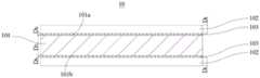
作为一个示例,图1示意性地示出了一种正极集流体10,请参照图1,正极集流体10包括层叠设置的支撑层101和导电层102,其中,在支撑层101的厚度方向上具有相对的第一表面101a和第二表面101b,导电层102设置于支撑层101的第一表面101a及第二表面101b上。As an example, FIG. 1 schematically shows a positive electrode
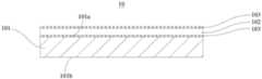
作为另一个示例,图2示意性地示出了另一种正极集流体10,请参照图2,正极集流体10包括层叠设置的支撑层101和导电层102,其中,在支撑层101的厚度方向上具有相对的第一表面101a和第二表面101b,导电层102设置于支撑层101的第一表面101a上。当然,导电层102也可以是设置于支撑层101的第二表面101b上。As another example, FIG. 2 schematically shows another positive electrode
进一步地,导电层102的厚度D1为300nm≤D1≤2μm,且正极集流体的拉伸应变ε为ε≥3%时,导电层102的方块电阻增长率T1为T1≥50%。Further, when the thickness D1 of the
本发明实施例的正极集流体10,通过设置支撑层101,将厚度较小的导电层102设置于支撑层101的至少一个表面,有利于改善电化学装置的重量能量密度,且在电化学装置发生穿钉等异常情况时,由于导电层102产生的毛刺较传统的金属铝箔大幅减小,且由于支撑层101的设置,以及穿钉时导电层102的方块电阻增长率急剧增加,使得电化学装置发生穿钉时具有较大的短路电阻,尤其是可以有效地形成“点断路”,从而能够提高电化学装置的安全性能。In the positive electrode
因此,采用本发明实施例的正极集流体10,使得电化学装置具有较高的穿钉安全性能。Therefore, the use of the positive electrode
进一步地,正极集流体10的拉伸应变ε为ε=1.5%时,导电层102的方块电阻增长率T2为T2≤30%。正极集流体10在正极极片20及电化学装置的加工及使用过程中,例如辊压或极片膨胀时,有时会被拉伸,使正极集流体10的拉伸应变ε为1.5%时导电层102的方块电阻增长率T2为T2≤30%,能够有效防止导电层102因拉伸形变而导致的电阻急剧增大,从而保证正极集流体10良好的导电和集流的性能,使得电化学装置具有低阻抗、且极化较小,从而使电化学装置兼具较高的电化学性能,其兼具较高的倍率性能和循环性能。Further, when the tensile strain ε of the positive electrode
更进一步地,正极集流体10的拉伸应变ε为1.5%时,导电层102的方块电阻增长率T2为T2≤15%。更进一步地,正极集流体10的拉伸应变ε为1.5%时,导电层102的方块电阻增长率T2为T2≤5%。Furthermore, when the tensile strain ε of the positive electrode
本实施例中,正极集流体10的拉伸应变ε可以根据公式ε=ΔL/L×100%计算,其中,ΔL是正极集流体10被拉伸产生的伸长量,L是正极集流体10的原长,即被拉伸之前的长度。In this embodiment, the tensile strain ε of the positive electrode
正极集流体10的拉伸应变为ε时,导电层102的方块电阻增长率T可以采用本领域已知的方法测定,作为示例,取正极集流体10裁剪成20mm×200mm的样品,采用四探针法测试样品的中心区域的方块电阻,记录为R1,然后使用高铁拉力机对样品的中心区域进行拉伸,设置初始位置,并使夹具之间的样品长度为50mm,以50mm/min速度进行拉伸,拉伸距离为样品原长L(50mm)与ε的乘积,即拉伸距离为ΔL,取下拉伸后的样品,测试夹具之间导电层102的方块电阻,记录为R2,根据公式T=(R2-R1)/R1×100%,计算得到正极集流体10的拉伸应变为ε时导电层102的方块电阻增长率T。When the tensile strain of the positive electrode
其中采用四探针法测试样品的方块电阻的方法如下:使用RTS-9型双电测四探针测试仪,测试环境为:常温23±2℃,0.1MPa,相对湿度≤65%。测试时,将待测样品进行表面清洁,然后水平置于测试台上,将四探针放下,使探针与待测样品表面有良好接触,然后调节自动测试模式标定样品的电流量程,在合适的电流量程下进行方块电阻的测量,并采集相同样品的8至10个数据点作为数据测量准确性和误差分析。最后取平均值记录为样品的方块电阻值。The method of using the four-point probe method to test the sheet resistance of the sample is as follows: use the RTS-9 double-electrical four-point probe tester, and the test environment is: normal temperature 23±2℃, 0.1MPa, relative humidity≤65%. During the test, clean the surface of the sample to be tested, then place it horizontally on the test table, put down the four probes, make good contact between the probe and the surface of the sample to be tested, and then adjust the automatic test mode to calibrate the current range of the sample. The measurement of sheet resistance is carried out under the current range of 100, and 8 to 10 data points of the same sample are collected as data measurement accuracy and error analysis. Finally, the average value is recorded as the sheet resistance value of the sample.
本发明实施例的正极集流体10,支撑层101的厚度D2优选为1μm≤D2≤20μm。该支撑层101具有足够的机械强度,在加工及使用过程中不易发生断裂,对导电层102起到良好的支撑和保护作用,保证正极集流体10良好的机械稳定性和工作稳定性,使正极集流体10具有较高的使用寿命;该支撑层101还有利于使电化学装置具有较小的体积及重量,从而提高电化学装置的能量密度。In the positive electrode
在一些实施例中,支撑层101的厚度D2的上限可以为20μm、18μm、15μm、12μm、10μm、8μm,下限可以为1μm、1.5μm、2μm、3μm、4μm、5μm、6μm、7μm,支撑层101的厚度D2的范围可以由上限和下限的任意数值组成。优选地,支撑层101的厚度D2为1μm≤D2≤15μm,进一步优选为2μm≤D2≤10μm,更优选为2μm≤D2≤6μm。In some embodiments, the upper limit of the thickness D2 of the
优选地,支撑层101的体积电阻率大于或等于1.0×10⁻⁵Ω·m。由于支撑层101的体积电阻率较大,在电化学装置发生穿钉等异常情况下,能够增大电化学装置发生内短路时的短路电阻,从而提高电化学装置的安全性能。支撑层101优选为具有绝缘性质的支撑层。Preferably, the volume resistivity of the
在本实施例中,支撑层101的体积电阻率是在20℃时的体积电阻率,可以采用本领域已知的方法测定。作为示例,测试在恒温常压低湿度房下进行(20℃,0.1MPa,RH≤20%),制备直径为20mm的圆片支撑层101样品(样品尺寸可根据测试仪器的实际尺寸调整),测试采用三电极测表面电阻率法(GB T 1410-2006),使用绝缘电阻测试仪(精度10Ω)进行。测试方法如下:将圆片样品放置在两个电极之间,并在两个电极之间施加一个电位差,产生的电流将分布在圆片样品的体内,并由皮安计或静电计来测量,以避免因在测量中计入表面泄露电流而产生测量误差。读数即为体积电阻率,单位为Ω·m。In this embodiment, the volume resistivity of the
进一步地,支撑层101的断裂伸长率大于或等于导电层102的断裂伸长率。由于支撑层101的断裂伸长率大于或等于导电层102的断裂伸长率,在电化学装置发生穿钉等异常情况时,支撑层101的毛刺能够包覆住导电层102的毛刺,并包覆在钉子表面,阻止导电层102的毛刺与对电极直接接触,由于支撑层101的体积电阻率较大,从而显著增大短路电阻,因此能够有效控制电化学装置的内短路,大幅度减小短路电流及减少短路产热量,提高电化学装置的穿钉安全性能。Further, the elongation at break of the
优选地,支撑层101的断裂伸长率大于导电层102的断裂伸长率。由于导电层102的延展性相对较小,支撑层101的延展性相对较大,在电化学装置发生穿钉等异常情况时,导电层102被迫延展,同时支撑层101包覆在钉子表面,使得钉子与导电层102相隔离,从而更好地使局部的导电网络被切断,防止电化学装置大面积甚至整个电化学装置发生内短路。这就可以更好地将穿钉等造成的电化学装置损坏局限于刺穿位点,仅形成“点断路”,而不影响电化学装置在一定时间内的正常工作。Preferably, the elongation at break of the
可选地,支撑层101的断裂伸长率大于或等于5%,优选地,支撑层101的断裂伸长率大于或等于10%。Optionally, the elongation at break of the
断裂伸长率可以采用本领域已知的方法测定,作为一个示例,取支撑层101裁剪成15mm×200mm的样品,在常温常压(25℃、0.1MPa)下使用高铁拉力机进行拉伸测试,设置初始位置使夹具之间样品长度为50mm长,拉伸速度为50mm/min,记录拉伸断裂时的设备位移y(mm),最后计算断裂伸长率为(y/50)×100%。导电层102的断裂伸长率可以采用同样的方法方便地测定。The elongation at break can be measured by a method known in the art. As an example, the
优选地,支撑层101的杨氏模量E为E≥4GPa。该支撑层101具有刚性,满足支撑层101对导电层102的支撑作用,确保正极集流体10的整体强度。在正极集流体10的加工过程中,支撑层101不会发生过大的延展或变形,能够防止支撑层101发生断带,并有利于提高支撑层101和导电层102之间结合的牢固度,不易发生脱离,保证正极集流体10具有较高的机械稳定性和工作稳定性,从而使电化学装置具有较高的电化学性能,如较长的循环寿命。Preferably, the Young's modulus E of the
更优选地,支撑层101的杨氏模量E为4GPa≤E≤20GPa,使得支撑层101具有刚性的同时还具有一定的承受变形的能力,能够在正极集流体10加工及使用过程中具有进行卷绕的柔性,更好地防止发生断带。More preferably, the Young's modulus E of the
支撑层101的杨氏模量E可以采用本领域已知的方法测定。作为示例,取支撑层101裁剪成15mm×200mm的样品,用万分尺量取样品的厚度h(μm),在常温常压(25℃、0.1MPa)下使用高铁拉力机进行拉伸测试,设置初始位置使夹具之间样品为50mm长,拉伸速度为50mm/min,记录拉伸至断裂的载荷L(N),设备位移y(mm),则应力ε(GPa)=L/(15×h),应变η=y/50,绘制应力应变曲线,取初始线性区曲线,该曲线的斜率即为杨氏模量E。The Young's modulus E of the
优选地,支撑层101与导电层102之间的结合力F≥100N/m,更优选为F≥400N/m。支撑层101与导电层102之间牢固结合,有效地发挥支撑层101对导电层102的支撑作用,还能够使支撑层101的毛刺更好地包覆住导电层102的毛刺,提高电化学装置的穿钉安全性能。Preferably, the bonding force between the
可以采用本领域已知的方法测试支撑层101与导电层102之间的结合力F,例如选用导电层102设置于支撑层101一面上的正极集流体10待测样品,宽度d为0.02m,在常温常压(25℃、0.1MPa)下,使用3M双面胶,均匀贴于不锈钢板上,再将待测样品均匀贴于双面胶上,使用高铁拉力机将待测样品的导电层102与支撑层101剥离,根据拉力和位移的数据图,读取最大拉力x(N),根据F=x/d计算得到导电层102与支撑层101之间的结合力F(N/m)。The bonding force F between the
优选地,支撑层101采用高分子材料及高分子基复合材料中的一种或多种。由于高分子材料和高分子基复合材料的密度相对金属较小,从而较传统的金属集流体明显减轻正极集流体10的重量,提高电化学装置的重量能量密度。Preferably, the
上述高分子材料,例如是聚酰胺类、聚酰亚胺类、聚酯类、聚烯烃类、聚炔烃类、硅氧烷聚合物、聚醚类、聚醇类、聚砜类、多糖类聚合物、氨基酸类聚合物、聚氮化硫类、芳环聚合物、芳杂环聚合物、环氧树脂、酚醛树脂、它们的衍生物、它们的交联物及它们的共聚物中的一种或多种。The above-mentioned polymer materials are, for example, polyamides, polyimides, polyesters, polyolefins, polyalkynes, siloxane polymers, polyethers, polyalcohols, polysulfones, and polysaccharides. In the polymer, amino acid-based polymer, polysulfur nitride, aromatic ring polymer, aromatic heterocyclic polymer, epoxy resin, phenolic resin, their derivatives, their cross-linked products and their copolymers one or more.
聚酰胺类高分子材料例如是聚己内酰胺(俗称尼龙6)、聚己二酰己二胺(俗称尼龙66)、聚对苯二甲酰对苯二胺(PPTA)、聚间苯二甲酰间苯二胺(PMIA);聚酯类高分子材料例如是聚对苯二甲酸乙二醇酯(PET)、聚对苯二甲酸丁二醇酯(PBT)、聚萘二甲酸乙二醇酯(PEN)、聚碳酸酯(PC);聚烯烃类高分子材料例如是聚乙烯(PE)、聚丙烯(PP)、聚丙乙烯(PPE);聚烯烃类高分子材料的衍生物例如是聚乙烯醇(PVA)、聚苯乙烯(PS)、聚氯乙烯(PVC)、聚偏氟乙烯(PVDF)、聚四氟乙烯(PTEE)、聚苯乙烯磺酸钠(PSS);聚炔烃类高分子材料例如是聚乙炔(Polyacetylene,简称PA);硅氧烷聚合物例如是硅橡胶(Siliconerubber);聚醚类高分子材料例如是聚甲醛(POM)、聚苯醚(PPO)、聚苯硫醚(PPS);聚醇类高分子材料例如是聚乙二醇(PEG);多糖类聚合物例如是纤维素、淀粉;氨基酸类聚合物例如是蛋白质;芳环聚合物例如是聚苯,再例如是聚对苯撑;芳杂环聚合物例如是聚吡咯(PPy)、聚苯胺(PAN)、聚噻吩(PT)、聚吡啶(PPY);聚烯烃基聚合物及其衍生物的共聚物例如是丙烯腈-丁二烯-苯乙烯共聚物(ABS)。Polyamide polymer materials such as polycaprolactam (commonly known as nylon 6), polyhexamethylene adipamide (commonly known as nylon 66), polyparaphenylene terephthalamide (PPTA), polyisophthalamide Phenylenediamine (PMIA); polyester polymer materials such as polyethylene terephthalate (PET), polybutylene terephthalate (PBT), polyethylene naphthalate ( PEN), polycarbonate (PC); polyolefin polymer materials such as polyethylene (PE), polypropylene (PP), polypropylene (PPE); derivatives of polyolefin polymer materials such as polyvinyl alcohol (PVA), polystyrene (PS), polyvinyl chloride (PVC), polyvinylidene fluoride (PVDF), polytetrafluoroethylene (PTEE), sodium polystyrene sulfonate (PSS); polyalkyne polymers Materials such as polyacetylene (PA); siloxane polymers such as silicone rubber; polyether polymers such as polyoxymethylene (POM), polyphenylene ether (PPO), polyphenylene sulfide (PPS); polyalcohol polymers such as polyethylene glycol (PEG); polysaccharide polymers such as cellulose and starch; amino acid polymers such as proteins; aromatic polymers such as polyphenylene, and For example, polyparaphenylene; aromatic heterocyclic polymers such as polypyrrole (PPy), polyaniline (PAN), polythiophene (PT), polypyridine (PPY); copolymers of polyolefin-based polymers and their derivatives An example is acrylonitrile-butadiene-styrene copolymer (ABS).
上述高分子基复合材料可以是包括上述的高分子材料和添加剂。通过添加剂能够调整高分子材料的体积电阻率、断裂伸长率及杨氏模量。前述添加剂可以是金属材料及无机非金属材料中的一种或多种。The above-mentioned polymer-based composite material may include the above-mentioned polymer material and additives. The volume resistivity, elongation at break and Young's modulus of the polymer material can be adjusted by additives. The aforementioned additives may be one or more of metallic materials and inorganic non-metallic materials.
金属材料例如是铝、铝合金、铜、铜合金、镍、镍合金、钛、钛合金、铁、铁合金、银及银合金中的一种或多种。无机非金属材料例如是碳基材料、氧化铝、二氧化硅、氮化硅、碳化硅、氮化硼、硅酸盐及氧化钛中的一种或多种,再例如是玻璃材料、陶瓷材料及陶瓷复合材料中的一种或多种。前述碳基材料例如是石墨、超导碳、乙炔黑、炭黑、科琴黑、碳点、碳纳米管、石墨烯及碳纳米纤维中的一种或多种。The metal material is, for example, one or more of aluminum, aluminum alloy, copper, copper alloy, nickel, nickel alloy, titanium, titanium alloy, iron, iron alloy, silver, and silver alloy. Inorganic non-metallic materials are, for example, one or more of carbon-based materials, alumina, silica, silicon nitride, silicon carbide, boron nitride, silicate and titanium oxide, and for example, glass materials, ceramic materials and one or more of ceramic composite materials. The aforementioned carbon-based materials are, for example, one or more of graphite, superconducting carbon, acetylene black, carbon black, Ketjen black, carbon dots, carbon nanotubes, graphene, and carbon nanofibers.
在一些实施例中,上述添加剂可以是金属材料包覆的碳基材料,例如镍包覆的石墨粉及镍包覆的碳纤维中的一种或多种。In some embodiments, the above-mentioned additive may be a carbon-based material coated with a metal material, such as one or more of nickel-coated graphite powder and nickel-coated carbon fiber.
优选地,支撑层101采用绝缘高分子材料及绝缘高分子基复合材料中的一种或多种。该支撑层101的体积电阻率较高,可以达到1.0×10⁹Ω·m以上,更好地提高电化学装置的安全性能。Preferably, the
进一步优选地,支撑层101采用聚对苯二甲酸乙二醇酯(PET)、聚对苯二甲酸丁二醇酯(PBT)、聚萘二甲酸乙二醇酯(PEN)、聚苯乙烯磺酸钠(PSS)及聚酰亚胺(PI)中的一种或多种。Further preferably, the
可以通过调整高分子材料的化学组成、分子量及分布、链结构和链构筑、聚集态结构、相结构、添加剂等,使支撑层101具有预定的体积电阻率、断裂伸长率及杨氏模量,以达到改善电化学装置安全性能及电化学性能的目的。The
本发明实施例的正极集流体10,支撑层101可以是如图1和图2显示的单层结构,也可以是两层以上的复合层结构,如两层、三层、四层等。In the cathode
作为复合层结构的支撑层101的一个示例,图3示意性地示出了另一种正极集流体10,请参照图3,支撑层101是由第一子层1011、第二子层1012及第三子层1013层叠设置形成的复合层结构。复合层结构的支撑层101具有相对的第一表面101a和第二表面101b,导电层102层叠设置在支撑层101的第一表面101a和第二表面101b上。当然,导电层102可以是仅设置于支撑层101的第一表面101a上,也可以是仅设置于支撑层101的第二表面101b上。As an example of the
当支撑层101为两层以上的复合层结构时,各子层的材料可以相同,也可以不同。When the
本发明实施例的正极集流体10,具有厚度显著降低的导电层102。优选地,导电层102的厚度D1为300nm≤D1≤2μm,电化学装置发生穿钉等异常情况下,该导电层102产生的毛刺较传统的金属集流体大幅度减小,且由于支撑层101的设置,以及穿钉时导电层102具有较大的拉伸方块电阻增长率,因此可以使得正极集流体10和正极极片20(如图10和图11所示)具有较大的短路电阻,从而改善电化学装置的穿钉安全性能。The positive electrode
此外,具有该厚度范围的导电层102还能够保证正极集流体10具有良好的导电和集流的性能,保证良好的电化学性能;还能够使得正极集流体10具有较低的重量,使电化学装置具有较高的重量能量密度。导电层102的厚度D1为300nm≤D1≤2μm,在正极集流体10加工及使用过程中导电层102不易发生破损,使正极集流体10具有良好的机械稳定性和工作稳定性及较高的使用寿命。In addition, the
在一些实施例中,导电层102的厚度D1的上限可以为2μm、1.8μm、1.5μm、1.2μm、1μm、900nm,导电层102的厚度D1的下限可为800nm、700nm、600nm、500nm、450nm、400nm、350nm、300nm,导电层102的厚度D1的范围可由上限或下限的任意数值组成。更优选地,导电层102的厚度D1为500nm≤D1≤1.5μm,有利于使正极集流体10更好地兼顾较高的安全性及导电性。In some embodiments, the upper limit of the thickness D1of the
优选地,导电层102的体积电阻率为2.5×10⁻⁸Ω·m~7.8×10⁻⁸Ω·m。导电层102的体积电阻率大于或等于2.5×10⁻⁸Ω·m,在穿钉等异常情况下,电化学装置发生内短路时具有较大的短路电阻,有利于电化学装置的安全性能;并且导电层102的体积电阻率小于或等于7.8×10⁻⁸Ω·m,保证正极集流体10良好的导电和集流的性能,从而使得采用该种正极集流体10的电化学装置具有低阻抗、并减小电池极化,有利于电化学装置的电化学性能。Preferably, the volume resistivity of the
进一步地,导电层102的体积电阻率优选为3.2×10⁻⁸Ω·m~7.8×10⁻⁸Ω·m。Further, the volume resistivity of the
导电层102的体积电阻率ρ为ρ=RS×d,其中,ρ的单位为Ω·m;RS为导电层102的方块电阻,单位为Ω;d为导电层102以m为单位的厚度。采用四探针法测试导电层102的方块电阻RS,方法如下:使用RTS-9型双电测四探针测试仪,测试环境为:常温23±2℃,0.1MPa,相对湿度≤65%,测试时,将正极集流体10样品进行表面清洁,然后水平置于测试台上,将四探针放下,使探针与样品的导电层102表面良好接触,然后调节自动测试模式标定样品的电流量程,在合适的电流量程下进行方块电阻的测量,并采集相同样品的8至10个数据点作为数据测量准确性和误差分析。最后取平均值记录为导电层102的方块电阻。The volume resistivity ρ of the
导电层102包括金属材料,例如是铝、铝合金、镍、镍合金、钛、钛合金、银及银合金中的一种或多种,优选为铝、铝合金、镍、镍合金、钛及银中的一种或多种。The
上述铝合金中铝元素的重量百分含量优选为90wt%以上。The weight percent content of the aluminum element in the above-mentioned aluminum alloy is preferably 90 wt% or more.
上述铝合金例如为铝锆合金。The above-mentioned aluminum alloy is, for example, an aluminum-zirconium alloy.
上述镍合金例如为镍铜合金。The above-mentioned nickel alloy is, for example, a nickel-copper alloy.
导电层102中还可以包括碳基导电材料及导电高分子材料中的一种或多种。The
碳基导电材料及导电高分子材料中的一种或多种在导电层102中的重量百分含量优选为10wt%以下。The weight percentage content of one or more of the carbon-based conductive material and the conductive polymer material in the
上述碳基导电材料,例如是石墨、超导碳、乙炔黑、炭黑、科琴黑、碳点、碳纳米管、石墨烯及碳纳米纤维中的一种或多种。The above-mentioned carbon-based conductive materials are, for example, one or more of graphite, superconducting carbon, acetylene black, carbon black, Ketjen black, carbon dots, carbon nanotubes, graphene and carbon nanofibers.
上述导电高分子材料,例如是聚氮化硫类、脂肪族共轭聚合物、芳环共轭聚合物及芳杂环共轭聚合物中的一种或多种。脂肪族共轭聚合物例如是聚乙炔,芳环共轭聚合物例如是聚苯、聚萘,其中聚苯例如是聚对苯撑,芳杂环共轭聚合物例如是聚吡咯、聚苯胺、聚噻吩、聚吡啶。还可以通过掺杂改性以提高导电高分子材料的电导率。The above-mentioned conductive polymer materials are, for example, one or more of polysulfur nitrides, aliphatic conjugated polymers, aromatic ring conjugated polymers and aromatic heterocyclic conjugated polymers. Aliphatic conjugated polymers are, for example, polyacetylene, aromatic ring conjugated polymers are, for example, polyphenylene, polynaphthalene, wherein polyphenylene is, for example, polyparaphenylene, and aromatic heterocyclic conjugated polymers are, for example, polypyrrole, polyaniline, Polythiophene, polypyridine. It can also be modified by doping to improve the conductivity of conductive polymer materials.
图4至图9分别示意性地示出了一种正极集流体10,请参照图4至图9,正极集流体10进一步包括保护层103。具体地,导电层102在自身厚度方向上包括相对的两个表面,保护层103层叠设置于导电层102的两个表面中的任意一者或两者上,以保护导电层102,防止导电层102发生化学腐蚀或机械破坏等损害,保证正极集流体10的工作稳定性及使用寿命,从而有利于电化学装置的安全性能及电化学性能。此外,保护层103还能够增强正极集流体10的机械强度。FIGS. 4 to 9 schematically show a positive electrode
保护层103的材料可以为金属、金属氧化物及导电碳中的一种或多种。The material of the
上述金属例如是镍、铬、镍基合金及铜基合金中的一种或多种。前述镍基合金是以纯镍为基体加入一种或几种其他元素所构成的合金,优选为镍铬合金。镍铬合金是金属镍和金属铬形成的合金,可选的,镍铬合金中镍与铬的重量比为1:99~99:1,如9:1。前述铜基合金是以纯铜为基体加入一种或几种其他元素所构成的合金,优选为镍铜合金。可选的,镍铜合金中镍与铜的重量比为1:99~99:1,如9:1。The above metals are, for example, one or more of nickel, chromium, nickel-based alloys and copper-based alloys. The aforementioned nickel-based alloy is an alloy formed by adding one or several other elements as the base of pure nickel, preferably a nickel-chromium alloy. The nickel-chromium alloy is an alloy formed by metal nickel and metal chromium. Optionally, the weight ratio of nickel to chromium in the nickel-chromium alloy is 1:99 to 99:1, such as 9:1. The aforementioned copper-based alloy is an alloy formed by adding one or several other elements as a base of pure copper, preferably a nickel-copper alloy. Optionally, the weight ratio of nickel to copper in the nickel-copper alloy is 1:99-99:1, such as 9:1.
上述金属氧化物例如是氧化铝、氧化钴、氧化铬及氧化镍中的一种或多种。The above-mentioned metal oxides are, for example, one or more of aluminum oxide, cobalt oxide, chromium oxide and nickel oxide.
上述导电碳例如是石墨、超导碳、乙炔黑、炭黑、科琴黑、碳点、碳纳米管、石墨烯、碳纳米纤维中的一种或多种,优选为炭黑、碳纳米管、乙炔黑及石墨烯中的一种或多种。The above-mentioned conductive carbon is, for example, one or more of graphite, superconducting carbon, acetylene black, carbon black, Ketjen black, carbon dots, carbon nanotubes, graphene, and carbon nanofibers, preferably carbon black, carbon nanotubes , one or more of acetylene black and graphene.
进一步地,保护层103例如采用金属或金属氧化物,即在导电层102上设置金属保护层或金属氧化物保护层。金属保护层和金属氧化物保护层的耐腐蚀性能较高,且硬度高、比表面积大,具有较高的综合性能。Further, the
作为一些示例,请参照图4和图5,正极集流体10包括层叠设置的支撑层101、导电层102和保护层103。其中,在支撑层101的厚度方向上具有相对的第一表面101a和第二表面101b,导电层102层叠设置于支撑层101的第一表面101a及第二表面101b中的至少一者上,保护层103层叠设置于导电层102的背向支撑层101的表面。As some examples, please refer to FIG. 4 and FIG. 5 , the positive electrode
在导电层102的背向支撑层101的表面上设置保护层103(下文简称为上保护层),对导电层102起到防化学腐蚀、防机械破坏的保护作用。特别地,金属保护层或金属氧化物保护层既可以保护导电层102,还可以改善正极集流体10与正极活性材料层201之间的界面,降低界面电阻,提高正极集流体10与正极活性材料层201之间的结合力,有利于降低极片极化,改善电化学装置的电化学性能。A protective layer 103 (hereinafter referred to as an upper protective layer) is provided on the surface of the
作为另一些示例,请参照图6和图7,正极集流体10包括层叠设置的支撑层101、导电层102和保护层103。其中,在支撑层101的厚度方向上具有相对的第一表面101a和第二表面101b,导电层102层叠设置于支撑层101的第一表面101a及第二表面101b中的至少一者上,保护层103层叠设置于导电层102的朝向支撑层101的表面。As another example, please refer to FIG. 6 and FIG. 7 , the positive electrode
在导电层102的朝向支撑层101的表面上设置保护层103(下文简称为下保护层),下保护层的相对的两个表面分别与导电层102和支撑层101连接,有利于提高对导电层102的支撑保护作用,同时起到防化学腐蚀、防机械损害的保护作用,并防止导电层102与支撑层101脱离。特别地,金属氧化物或金属保护层的硬度高、比表面积大,可以更好的起到上述保护作用。优选的为金属氧化物保护层,因为金属氧化物保护层的比表面积更大,硬度更高,因此更加有利于改善界面之间的结合力。A protective layer 103 (hereinafter referred to as the lower protective layer) is provided on the surface of the
作为又一些示例,请参照图8和图9,正极集流体10包括层叠设置的支撑层101、导电层102和保护层103。其中,在支撑层101的厚度方向上具有相对的第一表面101a和第二表面101b,导电层102层叠设置于支撑层101的第一表面101a及第二表面101b中的至少一者上,保护层103层叠设置于导电层102的背向支撑层101的表面及朝向支撑层101的表面上。As further examples, please refer to FIG. 8 and FIG. 9 , the positive electrode
在导电层102的两个表面上均设置保护层103,更加充分地保护导电层102。
可以理解的是,导电层102的两个表面上的保护层103,其材料可以相同、也可以不同,其厚度可以相同、也可以不同。It can be understood that, the
优选地,保护层103的厚度D3为1nm≤D3≤200nm、且D3≤0.1D1。如果保护层103太薄,则不足以起到保护导电层102的作用,太厚,则会降低电化学装置的能量密度。Preferably, the thickness D3 of the
在一些实施例中,保护层103的厚度D3的上限可以为200nm、180nm、150nm、120nm、100nm、80nm、60nm、55nm、50nm、45nm、40nm、30nm、20nm,保护层103的厚度D3的下限可以为1nm、2nm、5nm、8nm、10nm、12nm、15nm、18nm,保护层103的厚度D3的范围可由上限和下限的任意数值组成。优选地,保护层103的厚度D3为5nm≤D3≤200nm,更优选地为10nm≤D3≤200nm。In some embodiments, the upper limit of the thickness D3 of the
进一步地,当导电层102的两个表面均设置有保护层103时,位于导电层102的背向支撑层101的表面上的保护层103(上保护层)的厚度为Da,1nm≤Da≤200nm、且Da≤0.1D1;位于导电层102的朝向支撑层101的表面上的保护层103(下保护层)的厚度为Db,1nm≤Db≤200nm、且Db≤0.1D1。优选地,Da>Db,有利于保护层103对导电层102起到良好的防化学腐蚀、防机械损害的保护作用,同时使电化学装置具有较高的能量密度。更优选地,0.5Da≤Db≤0.8Da,能够更好的发挥保护层103的作用。Further, when both surfaces of the
导电层102可以是通过机械辊轧、粘结、气相沉积法(vapor deposition)、化学镀(Electroless plating)、电镀(Electroplating)中的至少一种手段形成于支撑层101上,其中优选气相沉积法或电镀,这样可以更好地实现导电层102与支撑层101之间的紧密结合。The
例如,通过气相沉积法将导电层102形成于支撑层101上,使得导电层102与支撑层101之间具有较高的结合力,有利于提高正极集流体10的机械稳定性、工作稳定性及安全性能。通过合理调控气相沉积过程条件,如沉积温度、沉积速率、沉积室的气氛条件等,可以使正极集流体10被拉伸时,导电层102的方块电阻增长率满足前文所述的要求,以改善正极集流体10的安全性能及电化学性能。For example, the
上述气相沉积法优选为物理气相沉积法(Physical Vapor Deposition,PVD)。物理气相沉积法优选蒸发法及溅射法中的至少一种;蒸发法优选真空蒸镀法(vacuumevaporating)、热蒸发法(Thermal Evaporation Deposition)及电子束蒸发法(electronbeam evaporation method,EBEM)中的至少一种,溅射法优选磁控溅射法(Magnetronsputtering)。The above-mentioned vapor deposition method is preferably a physical vapor deposition method (Physical Vapor Deposition, PVD). The physical vapor deposition method is preferably at least one of an evaporation method and a sputtering method; the evaporation method is preferably a vacuum evaporation method (vacuumevaporating), a thermal evaporation method (Thermal Evaporation Deposition) and an electron beam evaporation method (electron beam evaporation method, EBEM). At least one of the sputtering methods is preferably magnetron sputtering.
作为一个示例,通过真空蒸镀法形成导电层102,包括:将经过表面清洁处理的支撑层101置于真空镀室内,以1300℃~2000℃的高温将金属蒸发室内的高纯金属丝熔化蒸发,蒸发后的金属经过真空镀室内的冷却系统,最后沉积于支撑层101上,形成导电层102。As an example, forming the
保护层103可以是通过气相沉积法、原位形成法及涂布法中的至少一种手段形成于导电层102上。气相沉积法可以是如前文所述的气相沉积法。原位形成法优选原位钝化法,即在金属表面原位形成金属氧化物钝化层的方法。涂布法优选辊压涂布、挤压涂布、刮刀涂布及凹版涂布中的至少一种。The
优选地,保护层103通过气相沉积法及原位形成法中的至少一种手段形成于导电层102上,有利于使导电层102与保护层103之间具有较高的结合力,从而更好地发挥保护层102对正极集流体10的保护作用,并保证正极集流体10的工作性能。Preferably, the
当导电层102与支撑层101之间设置有保护层103(即下保护层)时,还可以是先将下保护层形成于支撑层101上,再将导电层102形成于下保护层上。下保护层可以是通过气相沉积法及涂布法中的至少一种手段形成于支撑层101上,其中优选气相沉积法,有利于使下保护层与支撑层101之间具有较高的结合力。导电层102可以是通过机械辊轧、粘结、气相沉积法、化学镀及电镀中的至少一种手段形成于下保护层上,其中优选气相沉积法及电镀中的至少一种,有利于使下保护层与导电层102之间具有较高的结合力。其中气相沉积法及涂布法可以是如前文所述的气相沉积法及涂布法。When a protective layer 103 (ie, a lower protective layer) is disposed between the
优选地,导电层102与保护层103之间的结合力F1≥100N/m,更优选为F1≥400N/m。Preferably, the bonding force between the
当保护层103还与支撑层101相连时,优选地,保护层103与支撑层101之间的结合力F2≥100N/m,更优选为F2≥400N/m。When the
导电层102与保护层103之间的结合力F1及保护层103与支撑层101之间的结合力F2可以参照上述支撑层101与导电层102之间的结合力F的测试方法测定。The bonding force F1 between the
正极极片Positive pole piece
本发明实施例第二方面提供一种正极极片20,包括层叠设置的正极集流体10及正极活性材料层201,其中正极集流体10为本发明实施例第一方面的正极集流体10。A second aspect of the embodiment of the present invention provides a
本发明实施例的正极极片20,由于采用了本发明实施例第一方面的正极集流体10,与传统的正极极片相比,具有较高的重量能量密度和良好的穿钉安全性能及电化学性能。The
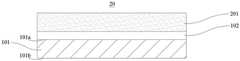
作为一个示例,请参照图10示出的一种正极极片20,正极极片20包括层叠设置的支撑层101、导电层102及正极活性材料层201,支撑层101包括相对的两个表面,导电层102层叠设置于支撑层101的两个表面上,正极活性材料层201层叠设置于导电层102的背向支撑层101的表面上。As an example, please refer to a
作为另一个示例,请参照图11示出的一种正极极片20,正极极片20包括层叠设置的支撑层101、导电层102及正极活性材料层201,支撑层101包括相对的两个表面,导电层102层叠设置于支撑层101的两个表面中的任意一者上,正极活性材料层201层叠设置于导电层102的背向支撑层101的表面上。As another example, please refer to a
本发明实施例的正极极片20,正极活性材料层201可以采用本领域已知的正极活性材料,能够进行离子的可逆嵌入/脱嵌。In the
例如用于锂离子二次电池的正极活性材料,可以为锂过渡金属复合氧化物,其中过渡金属可以是Mn、Fe、Ni、Co、Cr、Ti、Zn、V、Al、Zr、Ce及Mg中的一种或多种。锂过渡金属复合氧化物中还可以掺杂电负性大的元素,如S、F、Cl及I中的一种或多种,能够使正极活性材料具有较高的结构稳定性和电化学性能。作为示例,锂过渡金属复合氧化物例如为LiMn2O4、LiNiO2、LiCoO2、LiNi1-yCoyO2(0<y<1)、LiNiaCobAl1-a-bO2(0<a<1,0<b<1,0<a+b<1)、LiMn1-m-nNimConO2(0<m<1,0<n<1,0<m+n<1)、LiMPO4(M可以为Fe、Mn、Co中的一种或多种)及Li3V2(PO4)3中的一种或多种。For example, the positive electrode active material for lithium ion secondary battery can be lithium transition metal composite oxide, wherein the transition metal can be Mn, Fe, Ni, Co, Cr, Ti, Zn, V, Al, Zr, Ce and Mg one or more of. The lithium transition metal composite oxide can also be doped with elements with high electronegativity, such as one or more of S, F, Cl and I, which can make the cathode active material have high structural stability and electrochemical performance. . As an example, the lithium transition metal composite oxide is, for example, LiMn2 O4 , LiNiO2 , LiCoO2 , LiNi1-y Coy O2 (0<y<1), LiNia Cob Al1-ab O2 (0 <a<1, 0<b<1, 0<a+b<1), LiMn1-m-n NimCon O2 (0<m<1, 0<n<1, 0<m+n <1), LiMPO4 (M can be one or more of Fe, Mn, Co) and one or more of Li3 V2 (PO4 )3 .
可选地,正极活性材料层201还可以包括导电剂。作为示例,导电剂为石墨、超导碳、乙炔黑、炭黑、科琴黑、碳点、碳纳米管、石墨烯及碳纳米纤维中一种或多种。Optionally, the positive electrode
可选地,正极活性材料层201还可以包括粘结剂。作为示例,粘结剂为丁苯橡胶(SBR)、水性丙烯酸树脂(water-based acrylic resin)、羧甲基纤维素(CMC)、聚偏二氟乙烯(PVDF)、聚四氟乙烯(PTFE)、乙烯-醋酸乙烯酯共聚物(EVA)、聚乙烯醇(PVA)及聚乙烯醇缩丁醛(PVB)中的一种或多种。Optionally, the positive electrode
正极极片20可以按照本领域常规方法制备。通常将正极活性材料及可选的导电剂、粘结剂分散于溶剂(例如N-甲基吡咯烷酮,简称为NMP)中,形成均匀的正极浆料,将正极浆料涂覆在正极集流体10上,经烘干等工序后,得到正极极片20。The
电化学装置Electrochemical device
本发明实施例的第三方面提供一种电化学装置,电化学装置包括正极极片、负极极片、隔离膜和电解液,其中正极极片为本发明实施例第二方面的正极极片。A third aspect of the embodiments of the present invention provides an electrochemical device, the electrochemical device includes a positive pole piece, a negative pole piece, a separator, and an electrolyte, wherein the positive pole piece is the positive pole piece of the second aspect of the embodiment of the present invention.
上述电化学装置可以是锂离子二次电池、锂一次电池、钠离子电池、镁离子电池等,但并不限于此。The above electrochemical device may be a lithium ion secondary battery, a lithium primary battery, a sodium ion battery, a magnesium ion battery, or the like, but is not limited thereto.
由于电化学装置采用根据本发明实施例的第二方面提供的正极极片,使得本发明实施例的电化学装置具有较高的重量能量密度和良好的穿钉安全性能及电化学性能。Since the electrochemical device adopts the positive electrode plate provided according to the second aspect of the embodiment of the present invention, the electrochemical device of the embodiment of the present invention has a high gravimetric energy density and good safety performance and electrochemical performance of nailing.
上述负极极片可以是包括负极集流体及负极活性材料层。The above-mentioned negative electrode sheet may include a negative electrode current collector and a negative electrode active material layer.
负极集流体可以是金属箔材、涂炭金属箔材及多孔金属箔材。负极集流体可以采用铜、铜合金、镍、镍合金、铁、铁合金、钛、钛合金、银及银合金中的一种或多种。The negative electrode current collector can be metal foil, carbon-coated metal foil and porous metal foil. The negative electrode current collector can be one or more of copper, copper alloy, nickel, nickel alloy, iron, iron alloy, titanium, titanium alloy, silver and silver alloy.
负极活性材料层可以采用本领域已知的负极活性材料,能够进行离子的可逆嵌入/脱嵌。The negative electrode active material layer can use negative electrode active materials known in the art, which can perform reversible intercalation/deintercalation of ions.
例如用于锂离子二次电池的负极活性材料,可以为金属锂、天然石墨、人造石墨、中间相微碳球(简写为MCMB)、硬碳、软碳、硅、硅-碳复合物、SiO、Li-Sn合金、Li-Sn-O合金、Sn、SnO、SnO2、尖晶石结构的钛酸锂及Li-Al合金中的一种或多种。For example, the negative electrode active material for lithium ion secondary battery can be metal lithium, natural graphite, artificial graphite, mesophase microcarbon balls (abbreviated as MCMB), hard carbon, soft carbon, silicon, silicon-carbon composite, SiO One or more of Li-Sn alloy, Li-Sn-O alloy, Sn, SnO, SnO2, lithium titanate with spinel structure and Li-Al alloy.
可选地,负极活性材料层还可以包括粘结剂。作为示例,粘结剂为丁苯橡胶(SBR)、水性丙烯酸树脂(water-based acrylic resin)、羧甲基纤维素(CMC)、聚偏二氟乙烯(PVDF)、聚四氟乙烯(PTFE)、乙烯-醋酸乙烯酯共聚物(EVA)、聚乙烯醇(PVA)及聚乙烯醇缩丁醛(PVB)中的一种或多种。Optionally, the anode active material layer may further include a binder. As examples, the binder is styrene-butadiene rubber (SBR), water-based acrylic resin, carboxymethyl cellulose (CMC), polyvinylidene fluoride (PVDF), polytetrafluoroethylene (PTFE) , one or more of ethylene-vinyl acetate copolymer (EVA), polyvinyl alcohol (PVA) and polyvinyl butyral (PVB).
可选地,负极活性材料层还可以包括导电剂。作为示例,导电剂为石墨、超导碳、乙炔黑、炭黑、科琴黑、碳点、碳纳米管、石墨烯及碳纳米纤维中一种或多种。Optionally, the anode active material layer may further include a conductive agent. As an example, the conductive agent is one or more of graphite, superconducting carbon, acetylene black, carbon black, Ketjen black, carbon dots, carbon nanotubes, graphene, and carbon nanofibers.
负极极片可以按照本领域常规方法制备。通常将负极活性材料及可选的导电剂、粘结剂、增稠及分散剂分散于溶剂中,溶剂可以是NMP或去离子水,形成均匀的负极浆料,将负极浆料涂覆在负极集流体上,经烘干等工序后,得到负极极片。The negative pole piece can be prepared according to conventional methods in the art. Usually, the negative electrode active material and optional conductive agent, binder, thickening and dispersing agent are dispersed in a solvent, which can be NMP or deionized water, to form a uniform negative electrode slurry, and the negative electrode slurry is coated on the negative electrode On the current collector, after drying and other processes, a negative pole piece is obtained.
对上述隔离膜没有特别的限制,可以选用任意公知的具有电化学稳定性和化学稳定性的多孔结构隔离膜,例如可以是玻璃纤维、无纺布、聚乙烯、聚丙烯及聚偏二氟乙烯中的一种或多种的单层或多层薄膜。The above-mentioned separator is not particularly limited, and any well-known porous structure separator with electrochemical stability and chemical stability can be selected, such as glass fiber, non-woven fabric, polyethylene, polypropylene and polyvinylidene fluoride. One or more of the single-layer or multi-layer films.
上述电解液包括有机溶剂和电解质盐。有机溶剂作为在电化学反应中传输离子的介质,可以采用本领域已知的用于电化学装置电解液的有机溶剂。电解质盐作为离子的供源,可以是本领域已知的用于电化学装置电解液的电解质盐。The above-mentioned electrolytic solution includes an organic solvent and an electrolyte salt. As the organic solvent as a medium for transporting ions in the electrochemical reaction, organic solvents known in the art for use in electrolytes of electrochemical devices can be used. As a source of ions, the electrolyte salt may be an electrolyte salt known in the art to be used in an electrolyte for an electrochemical device.
例如用于锂离子二次电池的有机溶剂,可以为碳酸乙烯酯(EC)、碳酸丙烯酯(PC)、碳酸甲乙酯(EMC)、碳酸二乙酯(DEC)、碳酸二甲酯(DMC)、碳酸二丙酯(DPC)、碳酸甲丙酯(MPC)、碳酸乙丙酯(EPC)、碳酸丁烯酯(BC)、氟代碳酸乙烯酯(FEC)、甲酸甲酯(MF)、乙酸甲酯(MA)、乙酸乙酯(EA)、乙酸丙酯(PA)、丙酸甲酯(MP)、丙酸乙酯(EP)、丙酸丙酯(PP)、丁酸甲酯(MB)、丁酸乙酯(EB)、1,4-丁内酯(GBL)、环丁砜(SF)、二甲砜(MSM)、甲乙砜(EMS)、二乙砜(ESE)中的一种或多种,优选为两种以上。For example, the organic solvent used in lithium ion secondary batteries can be ethylene carbonate (EC), propylene carbonate (PC), ethyl methyl carbonate (EMC), diethyl carbonate (DEC), dimethyl carbonate (DMC) ), dipropyl carbonate (DPC), methyl propyl carbonate (MPC), ethyl propyl carbonate (EPC), butylene carbonate (BC), fluoroethylene carbonate (FEC), methyl formate (MF), Methyl acetate (MA), ethyl acetate (EA), propyl acetate (PA), methyl propionate (MP), ethyl propionate (EP), propyl propionate (PP), methyl butyrate ( One of MB), ethyl butyrate (EB), 1,4-butyrolactone (GBL), sulfolane (SF), dimethyl sulfone (MSM), methyl ethyl sulfone (EMS), and diethyl sulfone (ESE) or more, preferably two or more.
例如用于锂离子二次电池的电解质盐,可以为LiPF6(六氟磷酸锂)、LiBF4(四氟硼酸锂)、LiClO4(高氯酸锂)、LiAsF6(六氟砷酸锂)、LiFSI(双氟磺酰亚胺锂)、LiTFSI(双三氟甲磺酰亚胺锂)、LiTFS(三氟甲磺酸锂)、LiDFOB(二氟草酸硼酸锂)、LiBOB(二草酸硼酸锂)、LiPO2F2(二氟磷酸锂)、LiDFOP(二氟二草酸磷酸锂)及LiTFOP(四氟草酸磷酸锂)中的一种或多种。For example, electrolyte salts for lithium ion secondary batteries can be LiPF6 (lithium hexafluorophosphate), LiBF4 (lithium tetrafluoroborate), LiClO4 (lithium perchlorate), LiAsF6 (lithium hexafluoroarsenate), LiFSI ( Lithium Bisfluorosulfonimide), LiTFSI (Lithium Bistrifluoromethanesulfonimide), LiTFS (Lithium Trifluoromethanesulfonate), LiDFOB (Lithium Difluorooxalate Borate), LiBOB (Lithium Dioxalate Borate), LiPO One or more of2 F2 (lithium difluorophosphate), LiDFOP (lithium difluorobisoxalate phosphate) and LiTFOP (lithium tetrafluorooxalate phosphate).
将上述正极极片、隔离膜、负极极片按顺序堆叠好,使隔离膜处于正极极片、负极极片之间起到隔离的作用,得到电芯,也可以是经卷绕后得到电芯;将电芯置于包装外壳中,注入电解液并封口,制备电化学装置。The above-mentioned positive pole piece, separator, and negative pole piece are stacked in order, so that the separator is placed between the positive pole piece and the negative pole piece to play a role of isolation to obtain a battery core, or a battery core can be obtained by winding ; Place the cell in the packaging shell, inject the electrolyte and seal it to prepare an electrochemical device.
实施例Example
下述实施例更具体地描述了本发明公开的内容,这些实施例仅仅用于阐述性说明,因为在本发明公开内容的范围内进行各种修改和变化对本领域技术人员来说是明显的。除非另有声明,以下实施例中所报道的所有份、百分比、和比值都是基于重量计,而且实施例中使用的所有试剂都可商购获得或是按照常规方法进行合成获得,并且可直接使用而无需进一步处理,以及实施例中使用的仪器均可商购获得。The present disclosure is more specifically described by the following examples, which are for illustrative purposes only, since various modifications and changes within the scope of the present disclosure will be apparent to those skilled in the art. Unless otherwise stated, all parts, percentages, and ratios reported in the following examples are on a weight basis, and all reagents used in the examples are either commercially available or synthesized according to conventional methods, and can be directly Used without further processing, and the instruments used in the examples are commercially available.
制备方法Preparation
正极集流体的制备Preparation of cathode current collectors
选取预定厚度的支撑层并进行表面清洁处理,将经过表面清洁处理的支撑层置于真空镀室内,以1300℃~2000℃的高温将金属蒸发室内的高纯铝丝熔化蒸发,蒸发后的金属经过真空镀室内的冷却系统,最后沉积于支撑层的两个表面,形成导电层。Select a support layer with a predetermined thickness and carry out surface cleaning treatment, place the surface-cleaned support layer in a vacuum plating chamber, and melt and evaporate the high-purity aluminum wire in the metal evaporation chamber at a high temperature of 1300 ° C ~ 2000 ° C. The evaporated metal After passing through the cooling system in the vacuum plating chamber, it is finally deposited on both surfaces of the support layer to form a conductive layer.
正极极片的制备Preparation of positive electrode
将正极活性材料LiNi1/3Co1/3Mn1/3O2(NCM333)、导电炭黑、粘结剂聚偏二氟乙烯(PVDF)按93:2:5的重量比在适量的N-甲基吡咯烷酮(NMP)溶剂中充分搅拌混合,使其形成均匀的正极浆料;将正极浆料涂覆于正极集流体上,经烘干等工序后,得到正极极片。The positive active material LiNi1/3 Co1/3 Mn1/3 O2 (NCM333), conductive carbon black, and binder polyvinylidene fluoride (PVDF) were mixed in an appropriate amount of N in a weight ratio of 93:2:5. - Fully stirring and mixing in methylpyrrolidone (NMP) solvent to form a uniform positive electrode slurry; coating the positive electrode slurry on the positive electrode current collector, and after drying and other processes, a positive electrode pole piece is obtained.
常规正极极片的制备Preparation of conventional positive electrode sheet
与本申请的正极极片的制备方法不同的是,采用的是12μm的铝箔。Different from the preparation method of the positive electrode sheet of the present application, the aluminum foil of 12 μm is used.
负极集流体的制备Preparation of negative electrode current collectors
采用厚度为8μm的铜箔。A copper foil with a thickness of 8 μm was used.
常规负极极片的制备Preparation of conventional negative pole pieces
将负极活性材料石墨、导电炭黑、增稠剂羧甲基纤维素钠(CMC)、粘结剂丁苯橡胶乳液(SBR)按96.5:1.0:1.0:1.5的重量比在适量的去离子水中充分搅拌混合,使其形成均匀的负极浆料;将负极浆料涂覆于负极集流体上,经烘干等工序后,得到负极极片。The negative electrode active material graphite, conductive carbon black, thickener sodium carboxymethyl cellulose (CMC), and binder styrene-butadiene rubber emulsion (SBR) in a weight ratio of 96.5:1.0:1.0:1.5 in an appropriate amount of deionized water. Fully stirring and mixing to form a uniform negative electrode slurry; coating the negative electrode slurry on the negative electrode current collector, and after drying and other processes, a negative electrode pole piece is obtained.
电解液的制备Preparation of electrolyte
将体积比为3:7的碳酸乙烯酯(EC)和碳酸甲乙酯(EMC)混合均匀,得到有机溶剂,然后将1mol/L的LiPF6均匀溶解在上述有机溶剂中。Ethylene carbonate (EC) and ethyl methyl carbonate (EMC) in a volume ratio of 3:7 were mixed uniformly to obtain an organic solvent, and then 1 mol/L LiPF6 was uniformly dissolved in the above organic solvent.
锂离子二次电池的制备Preparation of Lithium-ion Secondary Batteries
将正极极片、隔离膜、负极极片依次层叠设置,然后卷绕成电芯并装入包装外壳中,隔离膜采用PP/PE/PP复合薄膜,其处于正极极片和负极极片之间起到隔离作用,将上述电解液注入到电芯中,之后经过密封、静置、热冷压、化成等工序,得到锂离子二次电池。The positive pole piece, the separator and the negative pole piece are stacked in sequence, and then wound into a battery cell and packed into the packaging shell. The separator is made of PP/PE/PP composite film, which is located between the positive pole piece and the negative pole piece. Playing the role of isolation, the above-mentioned electrolyte is injected into the battery core, and then the lithium ion secondary battery is obtained through the processes of sealing, standing, hot and cold pressing, and chemical formation.
测试部分test section
1.正极集流体的测试1. Test of positive current collector
支撑层的体积电阻率、正极集流体的拉伸应变ε为3%时导电层的方块电阻增长率T1、正极集流体的拉伸应变ε为1.5%时导电层的方块电阻增长率T2、以及支撑层的杨氏模量E分别采用前文所述的测试方法进行测试。The volume resistivity of the support layer, the sheet resistance growth rate T1 of the conductive layer when the tensile strain ε of the positive electrode current collector is 3%, and the sheet resistance growth rate T2 of the conductive layer when the tensile strain ε of the positive electrode current collector is 1.5% , and the Young's modulus E of the support layer were respectively tested by the test methods described above.
2.电池的性能测试2. Battery performance test
(1)循环性能测试(1) Cycle performance test
在25℃和45℃下,将锂离子二次电池以1C的倍率恒流充电至4.2V,再恒压充电至电流小于等于0.05C,再以1C的倍率恒流放电至2.8V,此为一个充放电循环,此次的放电容量即为第1次循环的放电容量。将锂离子二次电池按照上述方法进行1000次充放电循环,记录第1000次循环的放电容量。At 25°C and 45°C, the lithium-ion secondary battery is charged to 4.2V at a constant current rate of 1C, then charged at a constant voltage until the current is less than or equal to 0.05C, and then discharged at a constant current rate of 1C to 2.8V. One charge-discharge cycle, the discharge capacity of this time is the discharge capacity of the first cycle. The lithium ion secondary battery was subjected to 1000 charge-discharge cycles according to the above method, and the discharge capacity of the 1000th cycle was recorded.
锂离子二次电池1C/1C循环1000次后的容量保持率(%)=第1000次循环的放电容量/第1次循环的放电容量×100%。The capacity retention rate (%) of the lithium ion secondary battery after 1000 cycles of 1C/1C=the discharge capacity of the 1000th cycle/the discharge capacity of the 1st cycle×100%.
(2)穿钉测试(2) Nail penetration test
在25℃下,将锂离子二次电池以1C的倍率恒流充电至4.2V,再恒压充电至电流小于等于0.05C。之后将直径为8mm的钢针以25mm/s的速度刺透整个锂离子二次电池,并将钢针保留于锂离子二次电池中,监测锂离子二次电池在温度和电压方面的变化。At 25°C, the lithium ion secondary battery was charged to 4.2V with a constant current at a rate of 1C, and then charged with a constant voltage until the current was less than or equal to 0.05C. Afterwards, a steel needle with a diameter of 8 mm was pierced through the entire lithium ion secondary battery at a speed of 25 mm/s, and the steel needle was retained in the lithium ion secondary battery to monitor changes in temperature and voltage of the lithium ion secondary battery.
电池温度的测试:使用多路测温仪,分别于待穿钉的电池的针刺面和背面的几何中心附上感温线,待穿钉完毕后,进行五分钟的电池温度跟踪测试,然后记录下五分钟时的电池的温度,得到电池温升。Battery temperature test: Using a multi-channel thermometer, attach a temperature sensing line to the acupuncture surface and the geometric center of the back of the battery to be pierced. Record the temperature of the battery at five minutes to get the battery temperature rise.
电池电压的测试:将待穿钉的电池的正极和负极连接至内阻仪的测量端,待穿钉完毕后,进行五分钟的电池电压跟踪测试,然后记录下五分钟时的电池的电压。Battery voltage test: Connect the positive and negative electrodes of the battery to be pierced to the measuring end of the internal resistance meter. After the piercing is completed, perform a five-minute battery voltage tracking test, and then record the battery voltage at five minutes.
测试结果Test Results
1.本申请正极集流体的电化学性能以及在改善电化学装置的穿钉安全性能方面的作用。1. The electrochemical performance of the positive electrode current collector of the present application and its role in improving the safety performance of the piercing of the electrochemical device.
表1Table 1

表2Table 2

表2中,“*”表示基于正极极片3设置保护层;“**”表示基于正极极片5设置保护层。In Table 2, "*" indicates that the protective layer is provided based on the positive pole piece 3; "**" indicates that the protective layer is provided based on the positive pole piece 5.
表3table 3

表4Table 4


采用本申请实施例正极集流体的电池的循环寿命良好,与采用常规正极集流体电池的循环性能相当。这说明采用本申请实施例的正极集流体不会对正极极片和电池的电化学性能有明显的不利影响。尤其是设置有保护层的正极集流体制成的电池,1C/1C循环1000次后的容量保持率进一步获得提升,说明电池的可靠性更好。The cycle life of the battery using the positive electrode current collector of the embodiment of the present application is good, which is comparable to the cycle performance of the battery using the conventional positive electrode current collector. This shows that the use of the positive electrode current collectors of the embodiments of the present application will not have obvious adverse effects on the electrochemical performance of the positive electrode sheet and the battery. Especially for the battery made of the positive current collector provided with the protective layer, the capacity retention rate after 1000 cycles of 1C/1C is further improved, indicating that the reliability of the battery is better.
此外,采用本申请实施例的正极集流体可以大大改善锂离子电池的穿钉安全性能。从表4中的数据可以看到,采用常规正极集流体的电池,在穿钉的瞬间,电池温度骤升500℃,电压骤降至零,这说明在穿钉的瞬间,电池发生内短路,产生大量的热,电池瞬间发生热失控和毁坏而导致失效。而采用了本申请实施例的正极集流体的电池,在穿钉测试中,电池温升基本都可以被控制在10℃左右或10℃以下,且电池电压基本保持稳定,电池可以正常工作。In addition, the use of the positive electrode current collector of the embodiments of the present application can greatly improve the safety performance of the lithium ion battery for piercing the nails. From the data in Table 4, it can be seen that the battery using the conventional positive current collector, at the moment of piercing the stud, the battery temperature rises by 500 ℃, and the voltage drops to zero, which means that the battery has an internal short circuit at the moment of piercing the stud. A large amount of heat is generated, and the battery is instantly thermally runaway and destroyed, resulting in failure. For the battery using the positive current collector of the embodiment of the present application, in the nail penetration test, the temperature rise of the battery can basically be controlled at about 10°C or below, the battery voltage is basically stable, and the battery can work normally.
可见,在电池发生内短路的情况下,本申请实施例的正极集流体可极大地降低短路产热量,从而改善电池的安全性能;此外,还可将短路损坏对电池的影响局限于“点”范围,仅形成“点断路”,而不影响电池在短时间内的正常工作。It can be seen that in the case of an internal short circuit in the battery, the positive current collector of the embodiment of the present application can greatly reduce the short-circuit heat generation, thereby improving the safety performance of the battery; in addition, the impact of short-circuit damage on the battery can be limited to "points" range, only a "point open circuit" is formed, without affecting the normal operation of the battery in a short period of time.
2.T1值对于电化学装置的穿钉安全性能的作用2. The role of T1 value on the safety performance of electrochemical devices
表5table 5

表6Table 6


由表5和表6的数据可知,由于对比正极集流体1和对比正极集流体2,当其拉伸应变大于等于3%时,导电层的方块电阻增长率T1为T1<50%,在采用其的电池发生穿钉等异常情况时,电池温度骤升500℃以上,电压骤降至零,这说明在穿钉的瞬间,电池发生内短路,产生大量的热,电池瞬间发生热失控和毁坏而导致失效。It can be seen from the data in Table 5 and Table 6 that when the tensile strain of the comparative positive current collector 1 and the comparative positive current collector 2 is greater than or equal to 3%, the sheet resistance growth rate T1 of the conductive layer is T1 <50%, When the battery using it has abnormal conditions such as piercing, the temperature of the battery suddenly rises above 500°C, and the voltage drops to zero, which means that at the moment of piercing, the battery has an internal short circuit, which generates a lot of heat, and the battery is thermally out of control instantly. and damage resulting in failure.
而本申请的正极集流体的拉伸应变大于等于3%时,导电层的方块电阻增长率T1为T1≥50%,采用本申请正极集流体的电池在发生穿钉等异常情况时,电池温升基本都可以被控制在10℃以下,且电池电压基本保持稳定,电池可以正常工作。However, when the tensile strain of the positive electrode current collector of the present application is greater than or equal to 3%, the sheet resistance growth rate T1 of the conductive layer is T1 ≥ 50%. The temperature rise of the battery can basically be controlled below 10 ℃, and the battery voltage is basically stable, and the battery can work normally.
可见,在电池发生内短路的情况下,本申请实施例的正极集流体可极大地降低短路产热量,从而改善电池的安全性能;此外,还可将短路损坏对电池的影响局限于“点”范围,仅形成“点断路”,而不影响电池在短时间内的正常工作。It can be seen that in the case of an internal short circuit in the battery, the positive current collector of the embodiment of the present application can greatly reduce the short-circuit heat generation, thereby improving the safety performance of the battery; in addition, the impact of short-circuit damage on the battery can be limited to "points" range, only a "point open circuit" is formed, without affecting the normal operation of the battery in a short period of time.
3.T2值对电化学装置的影响3. The effect of T2 value on the electrochemical device
表7Table 7

表7中,铝合金的成分为:铝92.5wt%,其余为锆7.5wt%。In Table 7, the composition of the aluminum alloy is: aluminum 92.5 wt %, and the rest is zirconium 7.5 wt %.
对表7中的正极集流体进行过流测试,将正极集流体剪裁成100mm幅宽,在幅宽方向正中的位置涂布80mm宽的活性物质层并辊压制作成极片,将辊压后的极片沿幅宽方向剪裁成100mm×30mm的长条,每种极片剪裁5条。测试时,将极片样品两侧无涂膜的导电区分别连接到充放电机的正负极端,随后设置充放电机,使10A电流通过极片,保持10s极片不发生熔断即为通过测试,否则视为不通过。每组样品测试五个,过流测试结果示于下面的表8。The positive electrode current collectors in Table 7 were subjected to an overcurrent test. The positive electrode current collectors were cut to a width of 100 mm, and an active material layer with a width of 80 mm was applied to the center of the width direction and rolled to form a pole piece. The pole pieces are cut into strips of 100mm×30mm along the width direction, and 5 pieces of each pole piece are cut. During the test, connect the conductive areas without coating film on both sides of the pole piece sample to the positive and negative terminals of the charger and discharger respectively, and then set up the charger and discharge machine to make 10A current pass through the pole piece, and keep the pole piece without melting for 10s to pass the test. , otherwise it will be regarded as not passed. Five samples were tested for each set, and the overcurrent test results are shown in Table 8 below.
表8Table 8
正极集流体的拉伸应变为1.5%时,导电层的方块电阻增长率T不大于30%,此时,采用该正极集流体的正极极片在辊压之后,可以具有较好的导电性能。否则导电性能较差,在电池产品中实用价值不大。优选的,正极集流体的拉伸应变为1.5%时,导电层的方块电阻增长率T满足T≤15%,更优选的T≤5%。When the tensile strain of the positive electrode current collector is 1.5%, the sheet resistance growth rate T of the conductive layer is not greater than 30%. At this time, the positive electrode sheet using the positive electrode current collector can have better conductivity after rolling. Otherwise, the electrical conductivity is poor, and the practical value in battery products is not large. Preferably, when the tensile strain of the positive electrode current collector is 1.5%, the sheet resistance growth rate T of the conductive layer satisfies T≤15%, more preferably T≤5%.
4.本申请正极集流体在改善电化学装置的重量能量密度方面的作用4. The role of the positive electrode current collector of the present application in improving the gravimetric energy density of an electrochemical device
表9Table 9


表9中,正极集流体重量百分数是指单位面积正极集流体重量除以单位面积常规正极集流体重量的百分数。In Table 9, the percentage by weight of the positive electrode current collector refers to the percentage of the weight of the positive electrode current collector per unit area divided by the weight of the conventional positive electrode current collector per unit area.
相较于传统的铝箔正极集流体,采用本申请的正极集流体的重量都得到不同程度的减轻,从而可提升电池的重量能量密度。Compared with the traditional aluminum foil positive electrode current collector, the weight of the positive electrode current collector of the present application can be reduced to different degrees, so that the weight energy density of the battery can be improved.
以上所述,仅为本发明的具体实施方式,但本发明的保护范围并不局限于此,任何熟悉本技术领域的技术人员在本发明揭露的技术范围内,可轻易想到各种等效的修改或替换,这些修改或替换都应涵盖在本发明的保护范围之内。因此,本发明的保护范围应以权利要求的保护范围为准。The above are only specific embodiments of the present invention, but the protection scope of the present invention is not limited to this. Any person skilled in the art can easily think of various equivalents within the technical scope disclosed by the present invention. Modifications or substitutions should be included within the protection scope of the present invention. Therefore, the protection scope of the present invention should be subject to the protection scope of the claims.
Claims (19)
Priority Applications (5)
| Application Number | Priority Date | Filing Date | Title |
|---|---|---|---|
| CN201910351364.7ACN110943226B (en) | 2019-04-28 | 2019-04-28 | Positive current collector, positive pole piece and electrochemical device |
| CN202011198103.5ACN112259744B (en) | 2019-04-28 | 2019-04-28 | Positive current collector, positive pole piece, electrochemical device, electric automobile and electronic product |
| EP19927079.4AEP3944382B1 (en) | 2019-04-28 | 2019-12-12 | Positive electrode current collector, positive electrode plate, battery, and apparatus |
| PCT/CN2019/124825WO2020220685A1 (en) | 2019-04-28 | 2019-12-12 | Positive electrode current collector, positive electrode plate, battery, and device |
| US17/512,703US12444751B2 (en) | 2019-04-28 | 2021-10-28 | Positive current collector, positive electrode plate, battery, and apparatus |
Applications Claiming Priority (1)
| Application Number | Priority Date | Filing Date | Title |
|---|---|---|---|
| CN201910351364.7ACN110943226B (en) | 2019-04-28 | 2019-04-28 | Positive current collector, positive pole piece and electrochemical device |
Related Child Applications (1)
| Application Number | Title | Priority Date | Filing Date |
|---|---|---|---|
| CN202011198103.5ADivisionCN112259744B (en) | 2019-04-28 | 2019-04-28 | Positive current collector, positive pole piece, electrochemical device, electric automobile and electronic product |
Publications (2)
| Publication Number | Publication Date |
|---|---|
| CN110943226A CN110943226A (en) | 2020-03-31 |
| CN110943226Btrue CN110943226B (en) | 2020-11-17 |
Family
ID=69905666
Family Applications (2)
| Application Number | Title | Priority Date | Filing Date |
|---|---|---|---|
| CN201910351364.7AActiveCN110943226B (en) | 2019-04-28 | 2019-04-28 | Positive current collector, positive pole piece and electrochemical device |
| CN202011198103.5AActiveCN112259744B (en) | 2019-04-28 | 2019-04-28 | Positive current collector, positive pole piece, electrochemical device, electric automobile and electronic product |
Family Applications After (1)
| Application Number | Title | Priority Date | Filing Date |
|---|---|---|---|
| CN202011198103.5AActiveCN112259744B (en) | 2019-04-28 | 2019-04-28 | Positive current collector, positive pole piece, electrochemical device, electric automobile and electronic product |
Country Status (3)
| Country | Link |
|---|---|
| EP (1) | EP3944382B1 (en) |
| CN (2) | CN110943226B (en) |
| WO (1) | WO2020220685A1 (en) |
Families Citing this family (12)
| Publication number | Priority date | Publication date | Assignee | Title |
|---|---|---|---|---|
| CN111668491A (en)* | 2020-05-28 | 2020-09-15 | 江苏卓高新材料科技有限公司 | A current collector, pole piece and secondary battery having the same |
| CN111740044A (en)* | 2020-07-09 | 2020-10-02 | 夏笔文 | Composite foil and production process thereof |
| CN114730887B (en) | 2020-08-31 | 2023-12-26 | 宁德时代新能源科技股份有限公司 | Positive electrode current collector, positive electrode plate containing same, battery module, battery pack and device |
| CN112510206A (en)* | 2020-10-16 | 2021-03-16 | 江苏卓高新材料科技有限公司 | Current collector and battery and object with same |
| CN113066989A (en)* | 2021-03-23 | 2021-07-02 | 珠海冠宇电池股份有限公司 | Current collector, pole piece comprising same and electrochemical device |
| US20240154088A1 (en)* | 2021-03-31 | 2024-05-09 | Zeon Corporation | Electrode for electrochemical device and electrochemical device |
| CN113130911A (en)* | 2021-05-25 | 2021-07-16 | 厦门海辰新能源科技有限公司 | Current collector, pole piece and lithium battery |
| CN114188545B (en)* | 2021-12-07 | 2024-08-06 | 珠海冠宇电池股份有限公司 | Current collector, battery and electronic equipment |
| CN115084533A (en)* | 2022-07-08 | 2022-09-20 | 珠海冠宇电池股份有限公司 | A current collector and its application |
| CN115395020B (en)* | 2022-10-28 | 2023-03-07 | 宁德新能源科技有限公司 | Composite current collector, preparation method thereof, and electrochemical device |
| CN119050371A (en)* | 2023-05-29 | 2024-11-29 | 宁德时代新能源科技股份有限公司 | Composite current collector, negative electrode plate, secondary battery, power utilization device and preparation method |
| CN116598419A (en)* | 2023-06-29 | 2023-08-15 | 广州方邦电子股份有限公司 | Composite foil material, battery pole piece and electrochemical energy storage device |
Citations (2)
| Publication number | Priority date | Publication date | Assignee | Title |
|---|---|---|---|---|
| CN103855346A (en)* | 2012-11-29 | 2014-06-11 | 深圳市鹏远隔板有限公司 | Storage battery AGM separator, preparation method thereof and storage battery |
| CN104313386A (en)* | 2014-09-24 | 2015-01-28 | 襄阳锦翔光电科技股份有限公司 | Copper alloy for negative current collector of lithium ion battery |
Family Cites Families (9)
| Publication number | Priority date | Publication date | Assignee | Title |
|---|---|---|---|---|
| US6933077B2 (en)* | 2002-12-27 | 2005-08-23 | Avestor Limited Partnership | Current collector for polymer electrochemical cells and electrochemical generators thereof |
| JP5704413B2 (en)* | 2010-09-22 | 2015-04-22 | トヨタ自動車株式会社 | Nonaqueous electrolyte secondary battery |
| JP2012177171A (en)* | 2011-02-28 | 2012-09-13 | Sumitomo Light Metal Ind Ltd | Aluminum alloy foil for lithium ion battery electrode current collector, and method for producing the same |
| JP2013026057A (en)* | 2011-07-22 | 2013-02-04 | Sharp Corp | Collector and nonaqueous secondary battery |
| CN108155387B (en)* | 2016-12-06 | 2020-08-25 | 华为技术有限公司 | An elastic current collector and preparation method thereof, battery electrode sheet and flexible lithium ion battery |
| CN108281662B (en)* | 2017-01-12 | 2020-05-05 | 宁德时代新能源科技股份有限公司 | A current collector, its pole piece and battery and application |
| CN106910897A (en)* | 2017-03-02 | 2017-06-30 | 宁德时代新能源科技股份有限公司 | Current collector, pole piece thereof and battery |
| CN106898729A (en)* | 2017-03-27 | 2017-06-27 | 浙江大学 | Flexible current-collecting body, electrode and battery comprising the flexible current-collecting body |
| CN107123812B (en)* | 2017-04-14 | 2020-05-19 | 宁德时代新能源科技股份有限公司 | A positive electrode current collector, its preparation method and its application |
- 2019
- 2019-04-28CNCN201910351364.7Apatent/CN110943226B/enactiveActive
- 2019-04-28CNCN202011198103.5Apatent/CN112259744B/enactiveActive
- 2019-12-12EPEP19927079.4Apatent/EP3944382B1/enactiveActive
- 2019-12-12WOPCT/CN2019/124825patent/WO2020220685A1/ennot_activeCeased
Patent Citations (2)
| Publication number | Priority date | Publication date | Assignee | Title |
|---|---|---|---|---|
| CN103855346A (en)* | 2012-11-29 | 2014-06-11 | 深圳市鹏远隔板有限公司 | Storage battery AGM separator, preparation method thereof and storage battery |
| CN104313386A (en)* | 2014-09-24 | 2015-01-28 | 襄阳锦翔光电科技股份有限公司 | Copper alloy for negative current collector of lithium ion battery |
Also Published As
| Publication number | Publication date |
|---|---|
| CN110943226A (en) | 2020-03-31 |
| US20220052349A1 (en) | 2022-02-17 |
| EP3944382B1 (en) | 2025-01-08 |
| WO2020220685A1 (en) | 2020-11-05 |
| CN112259744A (en) | 2021-01-22 |
| CN112259744B (en) | 2022-08-02 |
| EP3944382A1 (en) | 2022-01-26 |
| EP3944382A4 (en) | 2022-07-06 |
Similar Documents
| Publication | Publication Date | Title |
|---|---|---|
| CN110943225B (en) | Positive current collector, positive pole piece and electrochemical device | |
| CN110943224B (en) | Negative current collector, negative pole piece and electrochemical device | |
| CN110943226B (en) | Positive current collector, positive pole piece and electrochemical device | |
| CN110943215B (en) | Lithium-ion secondary battery | |
| CN111180737B (en) | Lithium-ion secondary battery, cell and negative electrode | |
| CN112186193B (en) | Negative electrode current collector, negative electrode sheet and electrochemical device | |
| CN112186196B (en) | Positive electrode current collector, positive electrode plate and electrochemical device | |
| WO2021000503A1 (en) | Negative electrode current collector, negative electrode plate, electrochemical apparatus, battery module, battery pack, and device | |
| CN112186194B (en) | Positive electrode current collector, positive electrode plate and electrochemical device | |
| CN112186197B (en) | Positive electrode current collector, positive electrode sheet and electrochemical device | |
| US12444751B2 (en) | Positive current collector, positive electrode plate, battery, and apparatus |
Legal Events
| Date | Code | Title | Description |
|---|---|---|---|
| PB01 | Publication | ||
| PB01 | Publication | ||
| SE01 | Entry into force of request for substantive examination | ||
| SE01 | Entry into force of request for substantive examination | ||
| GR01 | Patent grant | ||
| GR01 | Patent grant |