CN1109189A - Method for identification of edge - Google Patents
Method for identification of edgeDownload PDFInfo
- Publication number
- CN1109189A CN1109189ACN94108211ACN94108211ACN1109189ACN 1109189 ACN1109189 ACN 1109189ACN 94108211 ACN94108211 ACN 94108211ACN 94108211 ACN94108211 ACN 94108211ACN 1109189 ACN1109189 ACN 1109189A
- Authority
- CN
- China
- Prior art keywords
- edge
- triangulation
- point
- contour
- height
- Prior art date
- Legal status (The legal status is an assumption and is not a legal conclusion. Google has not performed a legal analysis and makes no representation as to the accuracy of the status listed.)
- Pending
Links
Images


Classifications
- G—PHYSICS
- G06—COMPUTING OR CALCULATING; COUNTING
- G06T—IMAGE DATA PROCESSING OR GENERATION, IN GENERAL
- G06T1/00—General purpose image data processing
Landscapes
- Physics & Mathematics (AREA)
- General Physics & Mathematics (AREA)
- Engineering & Computer Science (AREA)
- Theoretical Computer Science (AREA)
- Image Analysis (AREA)
- Length Measuring Devices By Optical Means (AREA)
- Image Processing (AREA)
Abstract
Translated fromChineseDescription
Translated fromChinese本发明涉及三维变化的面形状所含的边缘的识别方法。The present invention relates to a method for recognizing edges contained in three-dimensionally changing surface shapes.
这类边缘,一般是采用三角测量法和浓淡图像法识别的。Such edges are generally identified by triangulation and shaded image methods.
但三角测量法和浓淡图像法各有长短,做不到正确识别边缘形状。However, the triangulation method and the shaded image method have their own advantages and disadvantages, and the edge shape cannot be correctly recognized.
本发明的课题是鉴于此问题,提供一种可以正确识别边缘形状的边缘识别方法。In view of this problem, an object of the present invention is to provide an edge recognition method capable of correctly recognizing an edge shape.
本发明的边缘识别方法有四种措施:第一种兼用三角测量法与浓淡图像法求出含边缘面的形状,由三角测量法的结果得出边缘高度,由浓淡图像法的结果得出边缘轮廓;第二种用三角测量法求出边缘轮廓,将构成该轮廓的点数据当中的一部分用作CAD起点、中点、终点,由CAD描绘边缘;第三种求出表示一面A的表达式a,并求出与该面相交的面B的表达式b,根据a、b两式求出两个面A、B的交线后,将此线判为边缘;第四种用三角测量法求出边缘轮廓,由接触法正确求出的结果修正此测定结果,每次用三角测量方法对边缘轮廓进行实际测定,都加进上述修正。The edge recognition method of the present invention has four kinds of measures: the first one uses triangulation method and shaded image method to obtain the shape of the surface containing the edge, draws the edge height by the result of triangulation method, and draws the edge height by the result of shaded image method Contour; the second method uses triangulation to obtain the edge contour, uses part of the point data that constitutes the contour as the starting point, midpoint, and end point of the CAD, and draws the edge by CAD; the third method obtains the expression representing a side A a, and calculate the expression b of the surface B that intersects with this surface, after calculating the intersection line of the two surfaces A and B according to the two formulas a and b, judge this line as an edge; the fourth method uses triangulation The edge profile is obtained, and the measurement result is corrected by the correct result obtained by the contact method, and the above-mentioned correction is added every time the edge profile is actually measured by the triangulation method.
这里,三角测量法是指,例如下文所述,利用光反射随物体表面三维形状产生偏移的办法,求得测定点高度(点数据)的方法。Here, the triangulation method refers to, for example, a method of obtaining the height of a measurement point (point data) using a method in which light reflection deviates from the three-dimensional shape of the object surface, as described below.
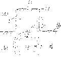
如图5所示,激光束10从投光部2经投光透镜3射到物体1三维形状的表面上。激光束10经物体1表面反射,通过受光透镜6进入CCD摄像检测部5。这种光学系统做成,按基准点11的高度反射激光束时,反射出的激光束10可在CCD摄像检测部5的基准位置17上测得。而经物体1表面与基准点11不等高的点12反射的激光束10,则在CCD摄像检测部5偏离基准位置17距离达L1的位置18上测得。这时,反射激光束的受光位置同测定点12的高度位置与基准点11的高度位置之差成正比变化。因此知道测定点12的高度位置(Z轴上的位置)。As shown in FIG. 5 , the
采用这种三角测量法实际求面形状时,由激光束10扫描物体1的表面。这种扫描范围是反射激光束10的受光位置纳入基准位置17的范围。反射激光束10的受光位置纳入基准位置17的范围内的面称为基准面。基准面的形状由例如特开昭64-26816号公报可知,可通过透镜形状等的调整,设定为曲面和平面等各种形状。测定点12作为该基准面内扫描测定对象的各点,在基准面内具有与基准点11相同高度的位置,或者是不同高度的位置。因为已知受光透镜6与基准点11的距离L2,受光透镜6与基准位置17的距离L3,以及受光透镜6与基准点11的连线同投光透镜3与基准点11的连线所成的夹角θ,因此物体1表面上的测定点12与基准点11之间的距离Z可直接求得。这样,通过激光束10的扫描就可以顺序得到与基准点11的距离为Z在二维上不同的测定点的高度位置,这些点数据储存起来,就可以识别三维形状。各测定点12XY轴上的位置(二维位置),通常表为上述距离Z加上基准点11与安装台14间距后的总距离Lz。另外,图中ZH表示可测定范围。In the actual determination of the surface shape using this triangulation method, the surface of the object 1 is scanned by the
这样,可以求得测定点12在Z轴上的位置,与XY轴上的位置。也就是说,可求出三维位置。另外,三角测量法得到的各测定点的点数据未必需要将它全部储存起来,还可以将例如,高度位置基本上一样变化的面,或者是高度位置不变的面的点数据除去不加以储存,来节约计算机的存储容量。In this way, the position of the
而浓淡图像法所用的措施是,由例如采用CCD等的摄像装置,获得物体具有三维形状的表面的二维图像信号,而且物体表面各像素的图像信号强度与三维形状相对应。由浓淡图像法的结果勾出边缘轮廓时,例如,可以根据所得到的图像信号,提取相邻像素间存在显著信号强度差的那些像素并连在一起,成为边缘的轮廓,或者是提取具有相同信号强度的那些像素并连在一起,成为边缘的轮廓。例如,物体表面的轮廓是球形的话,则将提取像素依次相连的轨迹也是球形的。The measure used in the shaded image method is to obtain a two-dimensional image signal of the surface of the object having a three-dimensional shape by, for example, an imaging device such as a CCD, and the intensity of the image signal of each pixel on the object surface corresponds to the three-dimensional shape. When the edge contour is drawn from the results of the shade image method, for example, according to the obtained image signal, those pixels with significant signal intensity difference between adjacent pixels can be extracted and connected together to become the edge contour, or the pixels with the same Those pixels of signal intensity are concatenated together to form the outline of the edge. For example, if the contour of the object surface is spherical, the trajectory connecting the extracted pixels in sequence is also spherical.
按照上述三角测量法,用例如激光束,扫描三维形状的物体表面,由此测量法求得以一定间隔存在的各测定点的高度位置,并作为点数据储存,就可以从这种储存数据识别该三维表面形状。According to the above-mentioned triangulation method, for example, a laser beam is used to scan the surface of a three-dimensional object, and the height position of each measurement point existing at a certain interval is obtained by this measurement method, and is stored as point data, and the point data can be identified from this stored data. 3D surface shape.
另外,由三角测量法求点数据时,如前所述,知道只是在可测定范围ZH内有高度变化,因而若光由浓淡图像法扫描,注意有浓淡变化的地方,仅仅对此变化区域附近直接进行借助于三角测量法的扫描的话,时间和存储容量便得到节约,后续处理也变得容易。接着,即使由三角测量法来求点数据,但由于有能读取高度变化的可测深度,所以这时要使测定点直接在可测定定范围以内,或者使测定始终在可测定范围以内,还是设置应用浓淡图像法等的跟踪机构为好。三角测量法当中的扫描,通常按一次扫描结束,便前移至下一位置再进行下一次扫描这种方法进行的,但这种扫描方法在移至下一扫描位置期间需要停止取数据,而且,即使移到了下一次扫描位置时,也无法立刻开始扫描,取数据要停到测定装置中断所带来的振动停振为止,很浪费时间。因此最好不是这种直线式扫描,而是曲折式扫描,并使这种曲折形状扫描线经数学处理变换为直线式扫描线。这种数学处理的例子有先将曲折式扫描线的轨迹建立函数,再利用此函数,由计算机进行运算,变换至直线式扫描线。In addition, when obtaining point data by the triangulation method, as mentioned above, it is known that there is only a height change within the measurable range ZH. Therefore, if the light is scanned by the shade image method, pay attention to the place where there is a shade change, and only the vicinity of the change area By performing the scanning directly by means of triangulation, time and memory capacity are saved and subsequent processing is facilitated. Next, even if the point data is obtained by the triangulation method, since there is a measurable depth that can read the height change, at this time, the measurement point should be directly within the measurable range, or the measurement should always be within the measurable range, It is better to provide a tracking mechanism using a gradation method or the like. The scan in the triangulation method is usually carried out according to the end of one scan, then move forward to the next position and then perform the next scan. However, this scan method needs to stop fetching data during the move to the next scan position, and , Even if it is moved to the next scanning position, scanning cannot be started immediately, and the data acquisition must be stopped until the vibration caused by the interruption of the measurement device stops, which is a waste of time. Therefore, it is better not to scan in a straight line, but to scan in a zigzag manner, and transform the zigzag scanning line into a straight line scanning line through mathematical processing. An example of this kind of mathematical processing is to first establish a function for the trajectory of the zigzag scanning line, and then use this function to perform calculations by a computer to transform it into a straight scanning line.
本发明的第一方法中,兼用三角测量法与浓淡图像法,求含边缘的面的形状。三角测量法如上文所述那样展现测定点高度位置,因而正确地求得高度位置。但在借助于激光束等的扫描中,由于要每隔一定间隔求测定点高度位置,因而某一测定点与下一测定点之间即使有因边缘而造成的高度位置变化,也无法正确展现边缘的二维位置,只能断定在两测定点间存在边缘。另一方面,浓淡图像法由受光元件所产生的明暗变化来获得形状变化轮廓,因而正确求得轮廓,但轮廓前后面的高度位置全无展现。因此,第一方法由三角测量法的结果给出边缘高度,而由浓淡图像法的结果给出边缘轮廓,这样就可以一起正确求出边缘的轮廓与高度位置的变化。In the first method of the present invention, the shape of the surface including the edge is obtained by using both the triangulation method and the shaded image method. The triangulation method reveals the height position of the measuring point as described above, so the height position is correctly obtained. However, in scanning with a laser beam, etc., since the height position of the measurement point must be obtained at regular intervals, even if there is a change in height position caused by an edge between a measurement point and the next measurement point, it cannot be displayed correctly. The two-dimensional position of the edge can only determine the existence of an edge between two measurement points. On the other hand, the shading image method obtains the contour of the shape change from the light and dark changes produced by the light receiving element, so the contour is obtained correctly, but the height positions of the front and back of the contour are not displayed at all. Therefore, in the first method, the edge height is given from the result of the triangulation method, and the edge profile is given from the result of the shaded image method, so that both the edge profile and the change in height position can be accurately obtained.
本发明第二方法中,采用三角测量法求边缘轮廓,但这种轮廓,严格来说,不清楚,较模糊。因此,凭人的经验和机械、电气方法提取构成此轮廓的点数据中的一部分,用作CAD(计算机辅助设计)的起点、中点、终点,由CAD正确描绘边缘。In the second method of the present invention, the triangulation method is used to obtain the edge contour, but strictly speaking, the contour is unclear and fuzzy. Therefore, a part of the point data constituting the outline is extracted by human experience and mechanical and electrical methods, and used as the starting point, midpoint, and end point of CAD (Computer Aided Design), and the edge is correctly drawn by CAD.
本发明第三方法,则通过运算求出表示某一面A的表达式a,同时也用运算求出表示与该面相交的面B的表达式b,根据a、b两式,经运算处理求得A、B两个面相交的线,并将此交线判断为边缘,由于经数学处理来求边缘轮廓,得出的轮廓比较清楚。In the third method of the present invention, the expression a representing a certain surface A is obtained by operation, and the expression b representing the surface B intersecting with the surface is also obtained by operation, and according to the two formulas a and b, the expression a is obtained through operation processing. Obtain the line where the two faces of A and B intersect, and judge this intersection line as an edge. Since the edge contour is obtained through mathematical processing, the obtained contour is relatively clear.
本发明第四方法,由接触法求出的正确结果对采用三角测量法求出的边缘轮廓作修正,每次采用三角测量法进行边缘轮廓的实际测定,就加入上述修正,因而三角测量法得到的边缘轮廓不仅清楚而且正确。In the fourth method of the present invention, the correct result obtained by the contact method corrects the edge profile obtained by the triangulation method, and each time the actual measurement of the edge profile is carried out by the triangulation method, the above-mentioned correction is added, so the triangulation method obtains The edge profile of is not only clear but correct.
本发明第一方法中,兼用三角测量法与浓淡图像法,由三角测量法的结果正确得出边缘高度,由浓淡图像法的结果正确得出边缘轮廓。判明边缘是有棱角的,还是带R(圆角)等状况。In the first method of the present invention, the triangulation method and the shaded image method are used together, and the edge height is accurately obtained from the result of the triangulation method, and the edge contour is accurately obtained from the result of the shaded image method. Determine whether the edge is angular or with R (rounded corners).
本发明第二方法中,将三角测量法得到的、构成边缘轮廓的点数据用作CAD的起点、中点、终点,边缘轮廓由CAD正确描绘。利用CAD,系统的构成简单,操作也容易。In the second method of the present invention, the point data constituting the edge profile obtained by triangulation is used as the start point, middle point, and end point of CAD, and the edge profile is correctly drawn by CAD. By using CAD, the system configuration is simple and the operation is also easy.
本发明第三方法中,是靠数学的处理求边缘轮廓的,因而可以获得清楚的轮廓。该第三方法中,面形状与面的交线例如可按如下那样求得。In the third method of the present invention, the edge contour is calculated by mathematical processing, so a clear contour can be obtained. In this third method, the line of intersection between the surface shape and the surface can be obtained, for example, as follows.
如图6(a)所表示的那样,分别从计量数据点群A和计量数据点群B求得最小二乘系平面SsatA和SsatB。As shown in FIG. 6( a ), the least squares system planes Ssat A and Ssat B are obtained from the measurement data point group A and the measurement data point group B, respectively.
Ssat=min∑(dxiyizi)2但,式中设面方程为S,任意点P(xi,yi,zi),S法向上与P的距离为dxiyizi。Ssat =min∑(dxiyizi)2However , in the formula, the surface equation is set as S, and the distance between S and P in the normal direction of any point P(xi, yi, zi) is dxiyizi.
接下来,如图6(b)所示,求出SsatA与SsatB的交线F=ax-by-cz+d的话,此交线F即边缘的轮廓。Next, as shown in FIG. 6(b), if the intersection line F=ax-by-cz+d of Ssat A and Ssat B is obtained, this intersection line F is the contour of the edge.
本发明第四方法,由实际的轮廓测定结果对用三角测量法求出的边缘轮廓作修正,因而得到的边缘轮廓不仅清楚而且正确。此第四方法中,所采用的由接触法求轮廓的办法,其例子有一面使极微细短针扫描,一面将每一扫描位置有无接触的信息存储下来。In the fourth method of the present invention, the edge profile obtained by the triangulation method is corrected based on the actual profile measurement results, so that the obtained edge profile is not only clear but also correct. In this fourth method, the method of obtaining the contour by the contact method is used, for example, while scanning with a very fine short needle, the information of whether there is contact or not is stored at each scanning position.
以下根据图示实施例的附图说明本发明,但本发明范围并不限于这些实施例。The present invention is explained below based on the drawings of illustrated embodiments, but the scope of the present invention is not limited to these embodiments.
图1是表示本发明第一方法实施例的说明图。Fig. 1 is an explanatory view showing an embodiment of the first method of the present invention.
图2是表示本发明第二方法实施例的说明图。Fig. 2 is an explanatory diagram showing an embodiment of the second method of the present invention.
图3是表示本发明第三方法实施例的说明图。Fig. 3 is an explanatory view showing an embodiment of the third method of the present invention.
图4是表示本发明第四方法实施例的说明图。Fig. 4 is an explanatory diagram showing a fourth method embodiment of the present invention.
图5是三角测量法的说明图。FIG. 5 is an explanatory diagram of a triangulation method.
图6是面与面交线求法的说明图。Fig. 6 is an explanatory diagram of the method for calculating the intersection line between surfaces.
首先说明第一方法的实施例。由三角测量法对图1(a)所示的、高位置面1a与低位置面1b之间具有垂直面1c的物体1求面形状时,例如该高位置面1a与垂直面1c所成的边缘1d,实际上应当在图1(b)虚线所示位置具有轮廓,但在三角测量法中,由于安排成一获得某一测定点P1的点数据,就进行扫描以获得下一测定点P2的点数据,所以,这种点数据所表示的轮廓变成图1(b)中具有双重圆所夹宽度W的模糊形状。但是,点数据表示的高度位置极为正确。另一方面,浓淡图像法在图1(b)虚线位置显出清楚的浓淡变化,因而可以正确判断这就是所得到的边缘1d的轮廓。因此,第一方法是同时采用三角测量法与浓淡图像法,由前者得出高度位置,而由后者得出轮廓位置这样进行的。First, an embodiment of the first method will be described. When the object 1 having the vertical plane 1c between the high position plane 1a and the low position plane 1b shown in Fig. The edge 1d should actually have a contour at the position shown by the dotted line in Figure 1(b), but in the triangulation method, it is arranged to scan to obtain the next measurement point P as soon as the point data of a certain measurement pointP1 is obtained.2 point data, so the outline represented by such point data becomes a blurred shape with a width W between double circles in Fig. 1(b). However, the height position represented by the point data is extremely correct. On the other hand, the shading image method shows a clear shading change at the position of the dotted line in Fig. 1(b), so it can be correctly judged that this is the contour of the obtained edge 1d. Therefore, in the first method, the triangulation method and the shaded image method are used simultaneously, and the height position is obtained from the former, and the contour position is obtained from the latter.
接下来说明本发明第二方法实施例。当得出如图2所示边缘1d的轮廓,首先用三角测量法取边缘部分的点数据。这种点数据群基本上是图中轮廓1c不清楚的数据。因此,从这些点数据群中,就图中半圆弧部分提取点P1、P2、P3,并当作圆的起点、中点、终点输入CAD,描绘出圆弧。还就图中键形部分提取点P3、P4、P5,并当作四边形的起点、中点、终点输入CAD,描绘出键形。Next, the second method embodiment of the present invention will be described. When the contour of the edge 1d as shown in Fig. 2 is obtained, the point data of the edge part is first obtained by triangulation. This point data group is basically data for which the outline 1c in the figure is unclear. Therefore, from these point data groups, points P1 , P2 , and P3 are extracted for the semicircular arc in the figure, and are input into CAD as the starting point, middle point, and end point of the circle to draw the arc. Also extract points P3 , P4 , and P5 for the key shape in the figure, and input them into CAD as the starting point, midpoint, and end point of the quadrilateral to draw the key shape.
接下来说明本发明第三方法实施例。要识别如图3所示的、水平面A与圆筒状垂直面B所成的边缘1d,首先,求出A的表达式a,同时也求出面B的表达式b。再根据a、b两式,经数学处理求出这两个A、B面的交线。这样的话,此线便与所要识别的边缘1d是一致的。Next, the third method embodiment of the present invention will be described. To identify the edge 1d formed by the horizontal plane A and the cylindrical vertical plane B as shown in Fig. 3, first, the expression a of A is obtained, and the expression b of the surface B is also obtained. Then, according to the two formulas a and b, the intersection line of the two planes A and B is obtained through mathematical processing. In this case, the line coincides with the edge 1d to be identified.
下面说明本发明第四方法实施例。这时,作为测定对象的物体,如图4所示,圆筒状垂直面C相对于水平面A的高度很小。这样的话,这时便与第三方法有所不同,垂直面C高度方向的点数据个数不够,无法识别面形状。这样,与无法识别某一面的情况相适应的办法即第四方法。这种方法,就面A求点数据时,可识别边缘1d的模糊轮廓。因此,由接触法来求出该边缘1d的正确轮廓。而且,采用该正确轮廓对点数据群的不清楚轮廓加以修正。接下来,当实际测定时,若向点数据群的实测值加进这种修正系数,进行修正的话,这种修正值就可给出正确清楚的边缘轮廓。The fourth method embodiment of the present invention will be described below. At this time, as an object to be measured, the height of the cylindrical vertical surface C relative to the horizontal surface A is small as shown in FIG. 4 . In this case, it is different from the third method at this time, the number of point data in the height direction of the vertical surface C is insufficient, and the surface shape cannot be recognized. In this way, the fourth method is a method suitable for the case where a certain side cannot be recognized. This method can identify the fuzzy outline of the edge 1d when finding point data on surface A. Therefore, the correct contour of the edge 1d is obtained by the contact method. Then, the unclear outline of the point data group is corrected using the correct outline. Next, when the correction is performed by adding such a correction coefficient to the actual measured value of the point data group during actual measurement, the corrected and clear edge contour can be given by this correction value.
本发明的边缘识别方法如上构成,边缘识别不仅正确,而且可以得到清楚的边缘轮廓。The edge recognition method of the present invention is constituted as above, and the edge recognition is not only correct, but also a clear edge outline can be obtained.
Claims (4)
Applications Claiming Priority (2)
| Application Number | Priority Date | Filing Date | Title |
|---|---|---|---|
| JP182579/93 | 1993-07-23 | ||
| JP5182579AJPH0737106A (en) | 1993-07-23 | 1993-07-23 | Edge recognition method |
Publications (1)
| Publication Number | Publication Date |
|---|---|
| CN1109189Atrue CN1109189A (en) | 1995-09-27 |
Family
ID=16120757
Family Applications (1)
| Application Number | Title | Priority Date | Filing Date |
|---|---|---|---|
| CN94108211APendingCN1109189A (en) | 1993-07-23 | 1994-07-22 | Method for identification of edge |
Country Status (3)
| Country | Link |
|---|---|
| JP (1) | JPH0737106A (en) |
| KR (1) | KR950004047A (en) |
| CN (1) | CN1109189A (en) |
Cited By (5)
| Publication number | Priority date | Publication date | Assignee | Title |
|---|---|---|---|---|
| CN1869993B (en)* | 2005-04-08 | 2010-05-12 | 达索系统公司 | Method of computer-aided design of a modeled object having several faces |
| CN101398899B (en)* | 2007-09-26 | 2011-03-30 | 鸿富锦精密工业(深圳)有限公司 | System and method for automatically identifying the type of edge of a sheet metal part |
| CN104616326A (en)* | 2015-02-02 | 2015-05-13 | 西北工业大学 | Composite material laying unit expanded outline correction method in numerical control blanking procedure |
| CN105057899A (en)* | 2015-08-18 | 2015-11-18 | 河海大学常州校区 | Scanned image recognition method applied to intelligent laser cutting |
| TWI627380B (en)* | 2016-11-23 | 2018-06-21 | 綠點高新科技股份有限公司 | Method And System For Estimating Contour Of A Surface Of A 3D Object |
Families Citing this family (3)
| Publication number | Priority date | Publication date | Assignee | Title |
|---|---|---|---|---|
| KR100450089B1 (en)* | 1997-12-29 | 2004-11-16 | 삼성테크윈 주식회사 | Method for calculating airfoil measurement coordinate values by using a cad system, specially enabling an exact measurement value with little measurement time, exact compensation for an inclined angle at each measurement point when evaluating a spatial free curve, and a minimum measurement error |
| JP6259262B2 (en)* | 2013-11-08 | 2018-01-10 | キヤノン株式会社 | Image processing apparatus and image processing method |
| CN117745718B (en)* | 2024-02-19 | 2024-07-02 | 工业云制造(四川)创新中心有限公司 | Information interaction method based on cloud manufacturing |
- 1993
- 1993-07-23JPJP5182579Apatent/JPH0737106A/enactivePending
- 1994
- 1994-07-21KRKR1019940017614Apatent/KR950004047A/ennot_activeCeased
- 1994-07-22CNCN94108211Apatent/CN1109189A/enactivePending
Cited By (6)
| Publication number | Priority date | Publication date | Assignee | Title |
|---|---|---|---|---|
| CN1869993B (en)* | 2005-04-08 | 2010-05-12 | 达索系统公司 | Method of computer-aided design of a modeled object having several faces |
| CN101398899B (en)* | 2007-09-26 | 2011-03-30 | 鸿富锦精密工业(深圳)有限公司 | System and method for automatically identifying the type of edge of a sheet metal part |
| CN104616326A (en)* | 2015-02-02 | 2015-05-13 | 西北工业大学 | Composite material laying unit expanded outline correction method in numerical control blanking procedure |
| CN104616326B (en)* | 2015-02-02 | 2017-04-26 | 西北工业大学 | Composite material laying unit expanded outline correction method in numerical control blanking procedure |
| CN105057899A (en)* | 2015-08-18 | 2015-11-18 | 河海大学常州校区 | Scanned image recognition method applied to intelligent laser cutting |
| TWI627380B (en)* | 2016-11-23 | 2018-06-21 | 綠點高新科技股份有限公司 | Method And System For Estimating Contour Of A Surface Of A 3D Object |
Also Published As
| Publication number | Publication date |
|---|---|
| KR950004047A (en) | 1995-02-17 |
| JPH0737106A (en) | 1995-02-07 |
Similar Documents
| Publication | Publication Date | Title |
|---|---|---|
| US4893183A (en) | Robotic vision system | |
| US7277187B2 (en) | Overhead dimensioning system and method | |
| CN109186491B (en) | Parallel multi-line laser measurement system and method based on homography matrix | |
| US5155775A (en) | Structured illumination autonomous machine vision system | |
| EP1493990B1 (en) | Surveying instrument and electronic storage medium | |
| EP0335035B1 (en) | Method and apparatus for measuring a three-dimensional curved surface shape | |
| JP2942454B2 (en) | Shape recognition method | |
| EP0391532B1 (en) | Apparatus for measuring three-dimensional curved surface shapes | |
| US6205240B1 (en) | Optical profile sensor | |
| JP3861781B2 (en) | Forward vehicle tracking system and forward vehicle tracking method | |
| US20040041996A1 (en) | Range finder and method | |
| US20080101688A1 (en) | 3D photogrammetry using projected patterns | |
| AU2002315499A1 (en) | Overhead dimensioning system and method | |
| US20030112449A1 (en) | Method for the extraction of image features caused by structure light using image reconstruction | |
| US6219063B1 (en) | 3D rendering | |
| CN1118483A (en) | Three dimentional shaped data processing method | |
| CN1109189A (en) | Method for identification of edge | |
| EP1519142A2 (en) | Method and system for image processing for profiling with structured light | |
| JP2007508557A (en) | Device for scanning three-dimensional objects | |
| JP3236362B2 (en) | Skin surface shape feature extraction device based on reconstruction of three-dimensional shape from skin surface image | |
| US6512844B2 (en) | 3D rendering | |
| JP3516118B2 (en) | Object recognition method and object recognition device | |
| CN114792342B (en) | A method, device, equipment and storage medium for locating line structure light | |
| JP3525712B2 (en) | Three-dimensional image capturing method and three-dimensional image capturing device | |
| JP2961140B2 (en) | Image processing method |
Legal Events
| Date | Code | Title | Description |
|---|---|---|---|
| C06 | Publication | ||
| PB01 | Publication | ||
| C10 | Entry into substantive examination | ||
| SE01 | Entry into force of request for substantive examination | ||
| C01 | Deemed withdrawal of patent application (patent law 1993) | ||
| WD01 | Invention patent application deemed withdrawn after publication |