CN110914728B - Optical fiber coupling device for changing light beam characteristics - Google Patents
Optical fiber coupling device for changing light beam characteristicsDownload PDFInfo
- Publication number
- CN110914728B CN110914728BCN201880047649.5ACN201880047649ACN110914728BCN 110914728 BCN110914728 BCN 110914728BCN 201880047649 ACN201880047649 ACN 201880047649ACN 110914728 BCN110914728 BCN 110914728B
- Authority
- CN
- China
- Prior art keywords
- fiber
- length
- input
- optical
- laser
- Prior art date
- Legal status (The legal status is an assumption and is not a legal conclusion. Google has not performed a legal analysis and makes no representation as to the accuracy of the status listed.)
- Active
Links
Images


Classifications
- G—PHYSICS
- G02—OPTICS
- G02B—OPTICAL ELEMENTS, SYSTEMS OR APPARATUS
- G02B27/00—Optical systems or apparatus not provided for by any of the groups G02B1/00 - G02B26/00, G02B30/00
- G02B27/09—Beam shaping, e.g. changing the cross-sectional area, not otherwise provided for
- G02B27/0927—Systems for changing the beam intensity distribution, e.g. Gaussian to top-hat
- G—PHYSICS
- G02—OPTICS
- G02F—OPTICAL DEVICES OR ARRANGEMENTS FOR THE CONTROL OF LIGHT BY MODIFICATION OF THE OPTICAL PROPERTIES OF THE MEDIA OF THE ELEMENTS INVOLVED THEREIN; NON-LINEAR OPTICS; FREQUENCY-CHANGING OF LIGHT; OPTICAL LOGIC ELEMENTS; OPTICAL ANALOGUE/DIGITAL CONVERTERS
- G02F1/00—Devices or arrangements for the control of the intensity, colour, phase, polarisation or direction of light arriving from an independent light source, e.g. switching, gating or modulating; Non-linear optics
- G02F1/01—Devices or arrangements for the control of the intensity, colour, phase, polarisation or direction of light arriving from an independent light source, e.g. switching, gating or modulating; Non-linear optics for the control of the intensity, phase, polarisation or colour
- G02F1/011—Devices or arrangements for the control of the intensity, colour, phase, polarisation or direction of light arriving from an independent light source, e.g. switching, gating or modulating; Non-linear optics for the control of the intensity, phase, polarisation or colour in optical waveguides, not otherwise provided for in this subclass
- G02F1/0115—Devices or arrangements for the control of the intensity, colour, phase, polarisation or direction of light arriving from an independent light source, e.g. switching, gating or modulating; Non-linear optics for the control of the intensity, phase, polarisation or colour in optical waveguides, not otherwise provided for in this subclass in optical fibres
- B—PERFORMING OPERATIONS; TRANSPORTING
- B22—CASTING; POWDER METALLURGY
- B22F—WORKING METALLIC POWDER; MANUFACTURE OF ARTICLES FROM METALLIC POWDER; MAKING METALLIC POWDER; APPARATUS OR DEVICES SPECIALLY ADAPTED FOR METALLIC POWDER
- B22F10/00—Additive manufacturing of workpieces or articles from metallic powder
- B22F10/20—Direct sintering or melting
- B—PERFORMING OPERATIONS; TRANSPORTING
- B22—CASTING; POWDER METALLURGY
- B22F—WORKING METALLIC POWDER; MANUFACTURE OF ARTICLES FROM METALLIC POWDER; MAKING METALLIC POWDER; APPARATUS OR DEVICES SPECIALLY ADAPTED FOR METALLIC POWDER
- B22F10/00—Additive manufacturing of workpieces or articles from metallic powder
- B22F10/30—Process control
- B22F10/31—Calibration of process steps or apparatus settings, e.g. before or during manufacturing
- B—PERFORMING OPERATIONS; TRANSPORTING
- B22—CASTING; POWDER METALLURGY
- B22F—WORKING METALLIC POWDER; MANUFACTURE OF ARTICLES FROM METALLIC POWDER; MAKING METALLIC POWDER; APPARATUS OR DEVICES SPECIALLY ADAPTED FOR METALLIC POWDER
- B22F10/00—Additive manufacturing of workpieces or articles from metallic powder
- B22F10/30—Process control
- B22F10/36—Process control of energy beam parameters
- B—PERFORMING OPERATIONS; TRANSPORTING
- B22—CASTING; POWDER METALLURGY
- B22F—WORKING METALLIC POWDER; MANUFACTURE OF ARTICLES FROM METALLIC POWDER; MAKING METALLIC POWDER; APPARATUS OR DEVICES SPECIALLY ADAPTED FOR METALLIC POWDER
- B22F3/00—Manufacture of workpieces or articles from metallic powder characterised by the manner of compacting or sintering; Apparatus specially adapted therefor ; Presses and furnaces
- B22F3/10—Sintering only
- B22F3/11—Making porous workpieces or articles
- B22F3/1103—Making porous workpieces or articles with particular physical characteristics
- B22F3/1109—Inhomogenous pore distribution
- B—PERFORMING OPERATIONS; TRANSPORTING
- B22—CASTING; POWDER METALLURGY
- B22F—WORKING METALLIC POWDER; MANUFACTURE OF ARTICLES FROM METALLIC POWDER; MAKING METALLIC POWDER; APPARATUS OR DEVICES SPECIALLY ADAPTED FOR METALLIC POWDER
- B22F3/00—Manufacture of workpieces or articles from metallic powder characterised by the manner of compacting or sintering; Apparatus specially adapted therefor ; Presses and furnaces
- B22F3/24—After-treatment of workpieces or articles
- B—PERFORMING OPERATIONS; TRANSPORTING
- B23—MACHINE TOOLS; METAL-WORKING NOT OTHERWISE PROVIDED FOR
- B23K—SOLDERING OR UNSOLDERING; WELDING; CLADDING OR PLATING BY SOLDERING OR WELDING; CUTTING BY APPLYING HEAT LOCALLY, e.g. FLAME CUTTING; WORKING BY LASER BEAM
- B23K26/00—Working by laser beam, e.g. welding, cutting or boring
- B23K26/02—Positioning or observing the workpiece, e.g. with respect to the point of impact; Aligning, aiming or focusing the laser beam
- B23K26/03—Observing, e.g. monitoring, the workpiece
- B23K26/032—Observing, e.g. monitoring, the workpiece using optical means
- B—PERFORMING OPERATIONS; TRANSPORTING
- B23—MACHINE TOOLS; METAL-WORKING NOT OTHERWISE PROVIDED FOR
- B23K—SOLDERING OR UNSOLDERING; WELDING; CLADDING OR PLATING BY SOLDERING OR WELDING; CUTTING BY APPLYING HEAT LOCALLY, e.g. FLAME CUTTING; WORKING BY LASER BEAM
- B23K26/00—Working by laser beam, e.g. welding, cutting or boring
- B23K26/02—Positioning or observing the workpiece, e.g. with respect to the point of impact; Aligning, aiming or focusing the laser beam
- B23K26/03—Observing, e.g. monitoring, the workpiece
- B23K26/034—Observing the temperature of the workpiece
- B—PERFORMING OPERATIONS; TRANSPORTING
- B23—MACHINE TOOLS; METAL-WORKING NOT OTHERWISE PROVIDED FOR
- B23K—SOLDERING OR UNSOLDERING; WELDING; CLADDING OR PLATING BY SOLDERING OR WELDING; CUTTING BY APPLYING HEAT LOCALLY, e.g. FLAME CUTTING; WORKING BY LASER BEAM
- B23K26/00—Working by laser beam, e.g. welding, cutting or boring
- B23K26/02—Positioning or observing the workpiece, e.g. with respect to the point of impact; Aligning, aiming or focusing the laser beam
- B23K26/03—Observing, e.g. monitoring, the workpiece
- B23K26/0342—Observing magnetic fields related to the workpiece
- B—PERFORMING OPERATIONS; TRANSPORTING
- B23—MACHINE TOOLS; METAL-WORKING NOT OTHERWISE PROVIDED FOR
- B23K—SOLDERING OR UNSOLDERING; WELDING; CLADDING OR PLATING BY SOLDERING OR WELDING; CUTTING BY APPLYING HEAT LOCALLY, e.g. FLAME CUTTING; WORKING BY LASER BEAM
- B23K26/00—Working by laser beam, e.g. welding, cutting or boring
- B23K26/02—Positioning or observing the workpiece, e.g. with respect to the point of impact; Aligning, aiming or focusing the laser beam
- B23K26/06—Shaping the laser beam, e.g. by masks or multi-focusing
- B23K26/062—Shaping the laser beam, e.g. by masks or multi-focusing by direct control of the laser beam
- B—PERFORMING OPERATIONS; TRANSPORTING
- B23—MACHINE TOOLS; METAL-WORKING NOT OTHERWISE PROVIDED FOR
- B23K—SOLDERING OR UNSOLDERING; WELDING; CLADDING OR PLATING BY SOLDERING OR WELDING; CUTTING BY APPLYING HEAT LOCALLY, e.g. FLAME CUTTING; WORKING BY LASER BEAM
- B23K26/00—Working by laser beam, e.g. welding, cutting or boring
- B23K26/02—Positioning or observing the workpiece, e.g. with respect to the point of impact; Aligning, aiming or focusing the laser beam
- B23K26/06—Shaping the laser beam, e.g. by masks or multi-focusing
- B23K26/064—Shaping the laser beam, e.g. by masks or multi-focusing by means of optical elements, e.g. lenses, mirrors or prisms
- B—PERFORMING OPERATIONS; TRANSPORTING
- B23—MACHINE TOOLS; METAL-WORKING NOT OTHERWISE PROVIDED FOR
- B23K—SOLDERING OR UNSOLDERING; WELDING; CLADDING OR PLATING BY SOLDERING OR WELDING; CUTTING BY APPLYING HEAT LOCALLY, e.g. FLAME CUTTING; WORKING BY LASER BEAM
- B23K26/00—Working by laser beam, e.g. welding, cutting or boring
- B23K26/02—Positioning or observing the workpiece, e.g. with respect to the point of impact; Aligning, aiming or focusing the laser beam
- B23K26/06—Shaping the laser beam, e.g. by masks or multi-focusing
- B23K26/067—Dividing the beam into multiple beams, e.g. multifocusing
- B—PERFORMING OPERATIONS; TRANSPORTING
- B23—MACHINE TOOLS; METAL-WORKING NOT OTHERWISE PROVIDED FOR
- B23K—SOLDERING OR UNSOLDERING; WELDING; CLADDING OR PLATING BY SOLDERING OR WELDING; CUTTING BY APPLYING HEAT LOCALLY, e.g. FLAME CUTTING; WORKING BY LASER BEAM
- B23K26/00—Working by laser beam, e.g. welding, cutting or boring
- B23K26/02—Positioning or observing the workpiece, e.g. with respect to the point of impact; Aligning, aiming or focusing the laser beam
- B23K26/06—Shaping the laser beam, e.g. by masks or multi-focusing
- B23K26/073—Shaping the laser spot
- B—PERFORMING OPERATIONS; TRANSPORTING
- B23—MACHINE TOOLS; METAL-WORKING NOT OTHERWISE PROVIDED FOR
- B23K—SOLDERING OR UNSOLDERING; WELDING; CLADDING OR PLATING BY SOLDERING OR WELDING; CUTTING BY APPLYING HEAT LOCALLY, e.g. FLAME CUTTING; WORKING BY LASER BEAM
- B23K26/00—Working by laser beam, e.g. welding, cutting or boring
- B23K26/20—Bonding
- B23K26/21—Bonding by welding
- B—PERFORMING OPERATIONS; TRANSPORTING
- B23—MACHINE TOOLS; METAL-WORKING NOT OTHERWISE PROVIDED FOR
- B23K—SOLDERING OR UNSOLDERING; WELDING; CLADDING OR PLATING BY SOLDERING OR WELDING; CUTTING BY APPLYING HEAT LOCALLY, e.g. FLAME CUTTING; WORKING BY LASER BEAM
- B23K26/00—Working by laser beam, e.g. welding, cutting or boring
- B23K26/34—Laser welding for purposes other than joining
- B23K26/342—Build-up welding
- B—PERFORMING OPERATIONS; TRANSPORTING
- B23—MACHINE TOOLS; METAL-WORKING NOT OTHERWISE PROVIDED FOR
- B23K—SOLDERING OR UNSOLDERING; WELDING; CLADDING OR PLATING BY SOLDERING OR WELDING; CUTTING BY APPLYING HEAT LOCALLY, e.g. FLAME CUTTING; WORKING BY LASER BEAM
- B23K26/00—Working by laser beam, e.g. welding, cutting or boring
- B23K26/36—Removing material
- B23K26/38—Removing material by boring or cutting
- B—PERFORMING OPERATIONS; TRANSPORTING
- B23—MACHINE TOOLS; METAL-WORKING NOT OTHERWISE PROVIDED FOR
- B23K—SOLDERING OR UNSOLDERING; WELDING; CLADDING OR PLATING BY SOLDERING OR WELDING; CUTTING BY APPLYING HEAT LOCALLY, e.g. FLAME CUTTING; WORKING BY LASER BEAM
- B23K26/00—Working by laser beam, e.g. welding, cutting or boring
- B23K26/70—Auxiliary operations or equipment
- B23K26/702—Auxiliary equipment
- B23K26/704—Beam dispersers, e.g. beam wells
- B—PERFORMING OPERATIONS; TRANSPORTING
- B29—WORKING OF PLASTICS; WORKING OF SUBSTANCES IN A PLASTIC STATE IN GENERAL
- B29C—SHAPING OR JOINING OF PLASTICS; SHAPING OF MATERIAL IN A PLASTIC STATE, NOT OTHERWISE PROVIDED FOR; AFTER-TREATMENT OF THE SHAPED PRODUCTS, e.g. REPAIRING
- B29C48/00—Extrusion moulding, i.e. expressing the moulding material through a die or nozzle which imparts the desired form; Apparatus therefor
- B29C48/03—Extrusion moulding, i.e. expressing the moulding material through a die or nozzle which imparts the desired form; Apparatus therefor characterised by the shape of the extruded material at extrusion
- B29C48/07—Flat, e.g. panels
- B29C48/08—Flat, e.g. panels flexible, e.g. films
- B—PERFORMING OPERATIONS; TRANSPORTING
- B29—WORKING OF PLASTICS; WORKING OF SUBSTANCES IN A PLASTIC STATE IN GENERAL
- B29C—SHAPING OR JOINING OF PLASTICS; SHAPING OF MATERIAL IN A PLASTIC STATE, NOT OTHERWISE PROVIDED FOR; AFTER-TREATMENT OF THE SHAPED PRODUCTS, e.g. REPAIRING
- B29C64/00—Additive manufacturing, i.e. manufacturing of three-dimensional [3D] objects by additive deposition, additive agglomeration or additive layering, e.g. by 3D printing, stereolithography or selective laser sintering
- B29C64/10—Processes of additive manufacturing
- B29C64/141—Processes of additive manufacturing using only solid materials
- B29C64/153—Processes of additive manufacturing using only solid materials using layers of powder being selectively joined, e.g. by selective laser sintering or melting
- B—PERFORMING OPERATIONS; TRANSPORTING
- B29—WORKING OF PLASTICS; WORKING OF SUBSTANCES IN A PLASTIC STATE IN GENERAL
- B29C—SHAPING OR JOINING OF PLASTICS; SHAPING OF MATERIAL IN A PLASTIC STATE, NOT OTHERWISE PROVIDED FOR; AFTER-TREATMENT OF THE SHAPED PRODUCTS, e.g. REPAIRING
- B29C64/00—Additive manufacturing, i.e. manufacturing of three-dimensional [3D] objects by additive deposition, additive agglomeration or additive layering, e.g. by 3D printing, stereolithography or selective laser sintering
- B29C64/20—Apparatus for additive manufacturing; Details thereof or accessories therefor
- B29C64/264—Arrangements for irradiation
- B—PERFORMING OPERATIONS; TRANSPORTING
- B33—ADDITIVE MANUFACTURING TECHNOLOGY
- B33Y—ADDITIVE MANUFACTURING, i.e. MANUFACTURING OF THREE-DIMENSIONAL [3-D] OBJECTS BY ADDITIVE DEPOSITION, ADDITIVE AGGLOMERATION OR ADDITIVE LAYERING, e.g. BY 3-D PRINTING, STEREOLITHOGRAPHY OR SELECTIVE LASER SINTERING
- B33Y10/00—Processes of additive manufacturing
- B—PERFORMING OPERATIONS; TRANSPORTING
- B33—ADDITIVE MANUFACTURING TECHNOLOGY
- B33Y—ADDITIVE MANUFACTURING, i.e. MANUFACTURING OF THREE-DIMENSIONAL [3-D] OBJECTS BY ADDITIVE DEPOSITION, ADDITIVE AGGLOMERATION OR ADDITIVE LAYERING, e.g. BY 3-D PRINTING, STEREOLITHOGRAPHY OR SELECTIVE LASER SINTERING
- B33Y30/00—Apparatus for additive manufacturing; Details thereof or accessories therefor
- B—PERFORMING OPERATIONS; TRANSPORTING
- B33—ADDITIVE MANUFACTURING TECHNOLOGY
- B33Y—ADDITIVE MANUFACTURING, i.e. MANUFACTURING OF THREE-DIMENSIONAL [3-D] OBJECTS BY ADDITIVE DEPOSITION, ADDITIVE AGGLOMERATION OR ADDITIVE LAYERING, e.g. BY 3-D PRINTING, STEREOLITHOGRAPHY OR SELECTIVE LASER SINTERING
- B33Y50/00—Data acquisition or data processing for additive manufacturing
- B33Y50/02—Data acquisition or data processing for additive manufacturing for controlling or regulating additive manufacturing processes
- G—PHYSICS
- G02—OPTICS
- G02B—OPTICAL ELEMENTS, SYSTEMS OR APPARATUS
- G02B27/00—Optical systems or apparatus not provided for by any of the groups G02B1/00 - G02B26/00, G02B30/00
- G02B27/09—Beam shaping, e.g. changing the cross-sectional area, not otherwise provided for
- G02B27/0933—Systems for active beam shaping by rapid movement of an element
- G—PHYSICS
- G02—OPTICS
- G02B—OPTICAL ELEMENTS, SYSTEMS OR APPARATUS
- G02B27/00—Optical systems or apparatus not provided for by any of the groups G02B1/00 - G02B26/00, G02B30/00
- G02B27/09—Beam shaping, e.g. changing the cross-sectional area, not otherwise provided for
- G02B27/0938—Using specific optical elements
- G02B27/0994—Fibers, light pipes
- G—PHYSICS
- G02—OPTICS
- G02B—OPTICAL ELEMENTS, SYSTEMS OR APPARATUS
- G02B6/00—Light guides; Structural details of arrangements comprising light guides and other optical elements, e.g. couplings
- G02B6/02—Optical fibres with cladding with or without a coating
- G—PHYSICS
- G02—OPTICS
- G02B—OPTICAL ELEMENTS, SYSTEMS OR APPARATUS
- G02B6/00—Light guides; Structural details of arrangements comprising light guides and other optical elements, e.g. couplings
- G02B6/02—Optical fibres with cladding with or without a coating
- G02B6/02042—Multicore optical fibres
- G—PHYSICS
- G02—OPTICS
- G02B—OPTICAL ELEMENTS, SYSTEMS OR APPARATUS
- G02B6/00—Light guides; Structural details of arrangements comprising light guides and other optical elements, e.g. couplings
- G02B6/02—Optical fibres with cladding with or without a coating
- G02B6/02057—Optical fibres with cladding with or without a coating comprising gratings
- G02B6/02076—Refractive index modulation gratings, e.g. Bragg gratings
- G02B6/0208—Refractive index modulation gratings, e.g. Bragg gratings characterised by their structure, wavelength response
- G02B6/021—Refractive index modulation gratings, e.g. Bragg gratings characterised by their structure, wavelength response characterised by the core or cladding or coating, e.g. materials, radial refractive index profiles, cladding shape
- G—PHYSICS
- G02—OPTICS
- G02B—OPTICAL ELEMENTS, SYSTEMS OR APPARATUS
- G02B6/00—Light guides; Structural details of arrangements comprising light guides and other optical elements, e.g. couplings
- G02B6/02—Optical fibres with cladding with or without a coating
- G02B6/02295—Microstructured optical fibre
- G02B6/023—Microstructured optical fibre having different index layers arranged around the core for guiding light by reflection, i.e. 1D crystal, e.g. omniguide
- G—PHYSICS
- G02—OPTICS
- G02B—OPTICAL ELEMENTS, SYSTEMS OR APPARATUS
- G02B6/00—Light guides; Structural details of arrangements comprising light guides and other optical elements, e.g. couplings
- G02B6/02—Optical fibres with cladding with or without a coating
- G02B6/02295—Microstructured optical fibre
- G02B6/02314—Plurality of longitudinal structures extending along optical fibre axis, e.g. holes
- G02B6/02342—Plurality of longitudinal structures extending along optical fibre axis, e.g. holes characterised by cladding features, i.e. light confining region
- G02B6/02347—Longitudinal structures arranged to form a regular periodic lattice, e.g. triangular, square, honeycomb unit cell repeated throughout cladding
- G—PHYSICS
- G02—OPTICS
- G02B—OPTICAL ELEMENTS, SYSTEMS OR APPARATUS
- G02B6/00—Light guides; Structural details of arrangements comprising light guides and other optical elements, e.g. couplings
- G02B6/02—Optical fibres with cladding with or without a coating
- G02B6/02295—Microstructured optical fibre
- G02B6/02314—Plurality of longitudinal structures extending along optical fibre axis, e.g. holes
- G02B6/02342—Plurality of longitudinal structures extending along optical fibre axis, e.g. holes characterised by cladding features, i.e. light confining region
- G02B6/02371—Cross section of longitudinal structures is non-circular
- G—PHYSICS
- G02—OPTICS
- G02B—OPTICAL ELEMENTS, SYSTEMS OR APPARATUS
- G02B6/00—Light guides; Structural details of arrangements comprising light guides and other optical elements, e.g. couplings
- G02B6/02—Optical fibres with cladding with or without a coating
- G02B6/02395—Glass optical fibre with a protective coating, e.g. two layer polymer coating deposited directly on a silica cladding surface during fibre manufacture
- G—PHYSICS
- G02—OPTICS
- G02B—OPTICAL ELEMENTS, SYSTEMS OR APPARATUS
- G02B6/00—Light guides; Structural details of arrangements comprising light guides and other optical elements, e.g. couplings
- G02B6/02—Optical fibres with cladding with or without a coating
- G02B6/036—Optical fibres with cladding with or without a coating core or cladding comprising multiple layers
- G02B6/03605—Highest refractive index not on central axis
- G02B6/03611—Highest index adjacent to central axis region, e.g. annular core, coaxial ring, centreline depression affecting waveguiding
- G—PHYSICS
- G02—OPTICS
- G02B—OPTICAL ELEMENTS, SYSTEMS OR APPARATUS
- G02B6/00—Light guides; Structural details of arrangements comprising light guides and other optical elements, e.g. couplings
- G02B6/02—Optical fibres with cladding with or without a coating
- G02B6/036—Optical fibres with cladding with or without a coating core or cladding comprising multiple layers
- G02B6/03694—Multiple layers differing in properties other than the refractive index, e.g. attenuation, diffusion, stress properties
- G—PHYSICS
- G02—OPTICS
- G02B—OPTICAL ELEMENTS, SYSTEMS OR APPARATUS
- G02B6/00—Light guides; Structural details of arrangements comprising light guides and other optical elements, e.g. couplings
- G02B6/10—Light guides; Structural details of arrangements comprising light guides and other optical elements, e.g. couplings of the optical waveguide type
- G02B6/14—Mode converters
- G—PHYSICS
- G02—OPTICS
- G02B—OPTICAL ELEMENTS, SYSTEMS OR APPARATUS
- G02B6/00—Light guides; Structural details of arrangements comprising light guides and other optical elements, e.g. couplings
- G02B6/24—Coupling light guides
- G02B6/255—Splicing of light guides, e.g. by fusion or bonding
- G—PHYSICS
- G02—OPTICS
- G02B—OPTICAL ELEMENTS, SYSTEMS OR APPARATUS
- G02B6/00—Light guides; Structural details of arrangements comprising light guides and other optical elements, e.g. couplings
- G02B6/24—Coupling light guides
- G02B6/42—Coupling light guides with opto-electronic elements
- G02B6/4201—Packages, e.g. shape, construction, internal or external details
- G02B6/4202—Packages, e.g. shape, construction, internal or external details for coupling an active element with fibres without intermediate optical elements, e.g. fibres with plane ends, fibres with shaped ends, bundles
- G02B6/4203—Optical features
- G—PHYSICS
- G02—OPTICS
- G02B—OPTICAL ELEMENTS, SYSTEMS OR APPARATUS
- G02B6/00—Light guides; Structural details of arrangements comprising light guides and other optical elements, e.g. couplings
- G02B6/24—Coupling light guides
- G02B6/42—Coupling light guides with opto-electronic elements
- G02B6/4201—Packages, e.g. shape, construction, internal or external details
- G02B6/4204—Packages, e.g. shape, construction, internal or external details the coupling comprising intermediate optical elements, e.g. lenses, holograms
- G02B6/4206—Optical features
- H—ELECTRICITY
- H01—ELECTRIC ELEMENTS
- H01S—DEVICES USING THE PROCESS OF LIGHT AMPLIFICATION BY STIMULATED EMISSION OF RADIATION [LASER] TO AMPLIFY OR GENERATE LIGHT; DEVICES USING STIMULATED EMISSION OF ELECTROMAGNETIC RADIATION IN WAVE RANGES OTHER THAN OPTICAL
- H01S3/00—Lasers, i.e. devices using stimulated emission of electromagnetic radiation in the infrared, visible or ultraviolet wave range
- H01S3/05—Construction or shape of optical resonators; Accommodation of active medium therein; Shape of active medium
- H01S3/06—Construction or shape of active medium
- H01S3/063—Waveguide lasers, i.e. whereby the dimensions of the waveguide are of the order of the light wavelength
- H01S3/067—Fibre lasers
- H—ELECTRICITY
- H01—ELECTRIC ELEMENTS
- H01S—DEVICES USING THE PROCESS OF LIGHT AMPLIFICATION BY STIMULATED EMISSION OF RADIATION [LASER] TO AMPLIFY OR GENERATE LIGHT; DEVICES USING STIMULATED EMISSION OF ELECTROMAGNETIC RADIATION IN WAVE RANGES OTHER THAN OPTICAL
- H01S5/00—Semiconductor lasers
- H01S5/005—Optical components external to the laser cavity, specially adapted therefor, e.g. for homogenisation or merging of the beams or for manipulating laser pulses, e.g. pulse shaping
- H01S5/0085—Optical components external to the laser cavity, specially adapted therefor, e.g. for homogenisation or merging of the beams or for manipulating laser pulses, e.g. pulse shaping for modulating the output, i.e. the laser beam is modulated outside the laser cavity
- B—PERFORMING OPERATIONS; TRANSPORTING
- B22—CASTING; POWDER METALLURGY
- B22F—WORKING METALLIC POWDER; MANUFACTURE OF ARTICLES FROM METALLIC POWDER; MAKING METALLIC POWDER; APPARATUS OR DEVICES SPECIALLY ADAPTED FOR METALLIC POWDER
- B22F12/00—Apparatus or devices specially adapted for additive manufacturing; Auxiliary means for additive manufacturing; Combinations of additive manufacturing apparatus or devices with other processing apparatus or devices
- B22F12/40—Radiation means
- B22F12/44—Radiation means characterised by the configuration of the radiation means
- B—PERFORMING OPERATIONS; TRANSPORTING
- B22—CASTING; POWDER METALLURGY
- B22F—WORKING METALLIC POWDER; MANUFACTURE OF ARTICLES FROM METALLIC POWDER; MAKING METALLIC POWDER; APPARATUS OR DEVICES SPECIALLY ADAPTED FOR METALLIC POWDER
- B22F12/00—Apparatus or devices specially adapted for additive manufacturing; Auxiliary means for additive manufacturing; Combinations of additive manufacturing apparatus or devices with other processing apparatus or devices
- B22F12/40—Radiation means
- B22F12/49—Scanners
- G—PHYSICS
- G02—OPTICS
- G02B—OPTICAL ELEMENTS, SYSTEMS OR APPARATUS
- G02B6/00—Light guides; Structural details of arrangements comprising light guides and other optical elements, e.g. couplings
- G02B6/10—Light guides; Structural details of arrangements comprising light guides and other optical elements, e.g. couplings of the optical waveguide type
- G02B6/12—Light guides; Structural details of arrangements comprising light guides and other optical elements, e.g. couplings of the optical waveguide type of the integrated circuit kind
- G02B2006/12083—Constructional arrangements
- G02B2006/12121—Laser
- G—PHYSICS
- G02—OPTICS
- G02B—OPTICAL ELEMENTS, SYSTEMS OR APPARATUS
- G02B26/00—Optical devices or arrangements for the control of light using movable or deformable optical elements
- G02B26/08—Optical devices or arrangements for the control of light using movable or deformable optical elements for controlling the direction of light
- G02B26/10—Scanning systems
- G02B26/101—Scanning systems with both horizontal and vertical deflecting means, e.g. raster or XY scanners
- G—PHYSICS
- G02—OPTICS
- G02B—OPTICAL ELEMENTS, SYSTEMS OR APPARATUS
- G02B6/00—Light guides; Structural details of arrangements comprising light guides and other optical elements, e.g. couplings
- G02B6/02—Optical fibres with cladding with or without a coating
- G02B6/02004—Optical fibres with cladding with or without a coating characterised by the core effective area or mode field radius
- G—PHYSICS
- G02—OPTICS
- G02B—OPTICAL ELEMENTS, SYSTEMS OR APPARATUS
- G02B6/00—Light guides; Structural details of arrangements comprising light guides and other optical elements, e.g. couplings
- G02B6/02—Optical fibres with cladding with or without a coating
- G02B6/028—Optical fibres with cladding with or without a coating with core or cladding having graded refractive index
- G02B6/0281—Graded index region forming part of the central core segment, e.g. alpha profile, triangular, trapezoidal core
- G—PHYSICS
- G02—OPTICS
- G02B—OPTICAL ELEMENTS, SYSTEMS OR APPARATUS
- G02B6/00—Light guides; Structural details of arrangements comprising light guides and other optical elements, e.g. couplings
- G02B6/02—Optical fibres with cladding with or without a coating
- G02B6/028—Optical fibres with cladding with or without a coating with core or cladding having graded refractive index
- G02B6/0288—Multimode fibre, e.g. graded index core for compensating modal dispersion
- G—PHYSICS
- G02—OPTICS
- G02B—OPTICAL ELEMENTS, SYSTEMS OR APPARATUS
- G02B6/00—Light guides; Structural details of arrangements comprising light guides and other optical elements, e.g. couplings
- G02B6/02—Optical fibres with cladding with or without a coating
- G02B6/036—Optical fibres with cladding with or without a coating core or cladding comprising multiple layers
- G02B6/03616—Optical fibres characterised both by the number of different refractive index layers around the central core segment, i.e. around the innermost high index core layer, and their relative refractive index difference
- G02B6/03622—Optical fibres characterised both by the number of different refractive index layers around the central core segment, i.e. around the innermost high index core layer, and their relative refractive index difference having 2 layers only
- G02B6/03627—Optical fibres characterised both by the number of different refractive index layers around the central core segment, i.e. around the innermost high index core layer, and their relative refractive index difference having 2 layers only arranged - +
- G—PHYSICS
- G02—OPTICS
- G02B—OPTICAL ELEMENTS, SYSTEMS OR APPARATUS
- G02B6/00—Light guides; Structural details of arrangements comprising light guides and other optical elements, e.g. couplings
- G02B6/02—Optical fibres with cladding with or without a coating
- G02B6/036—Optical fibres with cladding with or without a coating core or cladding comprising multiple layers
- G02B6/03616—Optical fibres characterised both by the number of different refractive index layers around the central core segment, i.e. around the innermost high index core layer, and their relative refractive index difference
- G02B6/03622—Optical fibres characterised both by the number of different refractive index layers around the central core segment, i.e. around the innermost high index core layer, and their relative refractive index difference having 2 layers only
- G02B6/03633—Optical fibres characterised both by the number of different refractive index layers around the central core segment, i.e. around the innermost high index core layer, and their relative refractive index difference having 2 layers only arranged - -
- G—PHYSICS
- G02—OPTICS
- G02B—OPTICAL ELEMENTS, SYSTEMS OR APPARATUS
- G02B6/00—Light guides; Structural details of arrangements comprising light guides and other optical elements, e.g. couplings
- G02B6/02—Optical fibres with cladding with or without a coating
- G02B6/036—Optical fibres with cladding with or without a coating core or cladding comprising multiple layers
- G02B6/03616—Optical fibres characterised both by the number of different refractive index layers around the central core segment, i.e. around the innermost high index core layer, and their relative refractive index difference
- G02B6/03638—Optical fibres characterised both by the number of different refractive index layers around the central core segment, i.e. around the innermost high index core layer, and their relative refractive index difference having 3 layers only
- G02B6/0365—Optical fibres characterised both by the number of different refractive index layers around the central core segment, i.e. around the innermost high index core layer, and their relative refractive index difference having 3 layers only arranged - - +
- G—PHYSICS
- G02—OPTICS
- G02B—OPTICAL ELEMENTS, SYSTEMS OR APPARATUS
- G02B6/00—Light guides; Structural details of arrangements comprising light guides and other optical elements, e.g. couplings
- G02B6/02—Optical fibres with cladding with or without a coating
- G02B6/036—Optical fibres with cladding with or without a coating core or cladding comprising multiple layers
- G02B6/03616—Optical fibres characterised both by the number of different refractive index layers around the central core segment, i.e. around the innermost high index core layer, and their relative refractive index difference
- G02B6/03688—Optical fibres characterised both by the number of different refractive index layers around the central core segment, i.e. around the innermost high index core layer, and their relative refractive index difference having 5 or more layers
- G—PHYSICS
- G02—OPTICS
- G02B—OPTICAL ELEMENTS, SYSTEMS OR APPARATUS
- G02B6/00—Light guides; Structural details of arrangements comprising light guides and other optical elements, e.g. couplings
- G02B6/24—Coupling light guides
- G02B6/26—Optical coupling means
- G02B6/262—Optical details of coupling light into, or out of, or between fibre ends, e.g. special fibre end shapes or associated optical elements
- G—PHYSICS
- G02—OPTICS
- G02B—OPTICAL ELEMENTS, SYSTEMS OR APPARATUS
- G02B6/00—Light guides; Structural details of arrangements comprising light guides and other optical elements, e.g. couplings
- G02B6/24—Coupling light guides
- G02B6/42—Coupling light guides with opto-electronic elements
- G02B6/4296—Coupling light guides with opto-electronic elements coupling with sources of high radiant energy, e.g. high power lasers, high temperature light sources
- G—PHYSICS
- G02—OPTICS
- G02F—OPTICAL DEVICES OR ARRANGEMENTS FOR THE CONTROL OF LIGHT BY MODIFICATION OF THE OPTICAL PROPERTIES OF THE MEDIA OF THE ELEMENTS INVOLVED THEREIN; NON-LINEAR OPTICS; FREQUENCY-CHANGING OF LIGHT; OPTICAL LOGIC ELEMENTS; OPTICAL ANALOGUE/DIGITAL CONVERTERS
- G02F1/00—Devices or arrangements for the control of the intensity, colour, phase, polarisation or direction of light arriving from an independent light source, e.g. switching, gating or modulating; Non-linear optics
- G02F1/01—Devices or arrangements for the control of the intensity, colour, phase, polarisation or direction of light arriving from an independent light source, e.g. switching, gating or modulating; Non-linear optics for the control of the intensity, phase, polarisation or colour
- G02F1/015—Devices or arrangements for the control of the intensity, colour, phase, polarisation or direction of light arriving from an independent light source, e.g. switching, gating or modulating; Non-linear optics for the control of the intensity, phase, polarisation or colour based on semiconductor elements having potential barriers, e.g. having a PN or PIN junction
- G02F1/0151—Devices or arrangements for the control of the intensity, colour, phase, polarisation or direction of light arriving from an independent light source, e.g. switching, gating or modulating; Non-linear optics for the control of the intensity, phase, polarisation or colour based on semiconductor elements having potential barriers, e.g. having a PN or PIN junction modulating the refractive index
- Y—GENERAL TAGGING OF NEW TECHNOLOGICAL DEVELOPMENTS; GENERAL TAGGING OF CROSS-SECTIONAL TECHNOLOGIES SPANNING OVER SEVERAL SECTIONS OF THE IPC; TECHNICAL SUBJECTS COVERED BY FORMER USPC CROSS-REFERENCE ART COLLECTIONS [XRACs] AND DIGESTS
- Y02—TECHNOLOGIES OR APPLICATIONS FOR MITIGATION OR ADAPTATION AGAINST CLIMATE CHANGE
- Y02P—CLIMATE CHANGE MITIGATION TECHNOLOGIES IN THE PRODUCTION OR PROCESSING OF GOODS
- Y02P10/00—Technologies related to metal processing
- Y02P10/25—Process efficiency
Landscapes
- Physics & Mathematics (AREA)
- Optics & Photonics (AREA)
- Engineering & Computer Science (AREA)
- General Physics & Mathematics (AREA)
- Mechanical Engineering (AREA)
- Chemical & Material Sciences (AREA)
- Manufacturing & Machinery (AREA)
- Materials Engineering (AREA)
- Plasma & Fusion (AREA)
- Nonlinear Science (AREA)
- Automation & Control Theory (AREA)
- Electromagnetism (AREA)
- Health & Medical Sciences (AREA)
- Toxicology (AREA)
- Crystallography & Structural Chemistry (AREA)
- Condensed Matter Physics & Semiconductors (AREA)
- Lasers (AREA)
- Optical Couplings Of Light Guides (AREA)
- Laser Beam Processing (AREA)
- Optical Modulation, Optical Deflection, Nonlinear Optics, Optical Demodulation, Optical Logic Elements (AREA)
- Optical Fibers, Optical Fiber Cores, And Optical Fiber Bundles (AREA)
- Mechanical Light Control Or Optical Switches (AREA)
- Light Guides In General And Applications Therefor (AREA)
Abstract
Description
Translated fromChinese相关申请的交叉引用CROSS-REFERENCE TO RELATED APPLICATIONS
本申请是2017年5月26日提交的美国专利申请No.15/607,399、2017年5月26日提交的美国专利申请No.15/607,410、2017年5月26日提交的美国专利申请No.15/607,411和2017年5月26日提交的专利合作条约申请PCT/US2017/034848的部分延续,这些申请都要求2016年9月29日提交的美国临时专利申请No.62/401,650的权益。所有这些申请的全部内容通过引用结合于此。This application is US Patent Application No. 15/607,399, filed on May 26, 2017, US Patent Application No. 15/607,410, filed May 26, 2017, and US Patent Application No. 15/607,411 and a continuation-in-part of Patent Cooperation Treaty Application PCT/US2017/034848, filed May 26, 2017, both claiming the benefit of US Provisional Patent Application No. 62/401,650, filed September 29, 2016. The entire contents of all of these applications are incorporated herein by reference.
技术领域technical field
本公开涉及用于修改激光束特性的方法和设备。The present disclosure relates to methods and apparatus for modifying laser beam characteristics.
背景技术Background technique
激光束空间和发散度分布(“光束特性”)的控制在许多应用中都很重要。在许多传统的光学加工系统中,激光束经由光纤和从光纤接收光束的光学器件引导至工件。虽然从光纤接收光束的光学器件可以产生选定的光束特性,但是在不将显著的复杂性、成本、尺寸、重量、光损耗或其他不期望的特性引入光学系统的情况下,这种光束特性往往难以改变。通常,光束传送光纤输出端的光束特性是固定的,并且传送光纤下游的光学器件(例如,加工头)将光束转换成具有另一组固定特性的光束(例如,通过对传送光纤的输出进行成像)。由于相同的原因,随着加工或其他应用需求的变化(或在需要多光束轮廓的应用中),调整可用的激光器以满足变化的需求,这可能具有挑战性。Control of laser beam spatial and divergence distribution ("beam properties") is important in many applications. In many conventional optical processing systems, a laser beam is directed to a workpiece via an optical fiber and optics that receive the beam from the optical fiber. While optics that receive the beam from an optical fiber can produce selected beam characteristics, such beam characteristics cannot be achieved without introducing significant complexity, cost, size, weight, optical loss, or other undesirable characteristics into the optical system. Often difficult to change. Typically, the beam properties at the output end of the beam delivery fiber are fixed, and optics downstream of the delivery fiber (eg, a processing head) convert the beam into a beam with another set of fixed properties (eg, by imaging the output of the delivery fiber) . For the same reason, as processing or other application needs change (or in applications requiring multiple beam profiles), it can be challenging to adjust the available lasers to meet changing needs.
其他实际问题使得现场光束修改变得困难。许多高功率激光系统包括安全联锁和功率监控系统,以给操作员提供安全并控制信号,这些信号有助于检测激光输出异常,从而允许在光学损坏之前进行激光修复或调整。这种联锁和监控系统是内置的,并且许多期望的重新配置使这些安全措施无效,或者需要复杂、精细的调整来重置。Other practical issues make in-situ beam modification difficult. Many high-power laser systems include safety interlocks and power monitoring systems to provide operators with safety and control signals that help detect laser output anomalies, allowing laser repair or adjustment before optical damage. This interlocking and monitoring system is built in, and many desired reconfigurations render these safety measures ineffective or require complex, fine-tuned adjustments to reset.
虽然光纤拼接在通信应用中非常简单,但将拼接引入高功率激光系统可能具有挑战性。用于将高功率激光耦合到其他光纤的拼接通常必须封装、消除应变、涂覆或以其他方式机械保护,并且拼接区域通常必须进行光学和热监控,以检测不可接受的操作条件。因此,在这种应用中拼接光纤往往是不切实际的,特别是对于通常无法接触到激光器制造商所使用的工艺和装配工具的最终用户。因此,需要改进的方法来提供可变和可控的光束轮廓,尤其是适合于重新配置已安装的高功率激光器的方法。While fiber splicing is straightforward in communications applications, introducing splicing into high-power laser systems can be challenging. Splices used to couple high power lasers to other fibers must often be encapsulated, strain relieved, coated, or otherwise mechanically protected, and the splice area must often be optically and thermally monitored to detect unacceptable operating conditions. As a result, splicing fibers in such applications is often impractical, especially for end users who typically do not have access to the process and assembly tools used by laser manufacturers. Therefore, there is a need for improved methods to provide variable and controllable beam profiles, especially methods suitable for reconfiguring installed high power lasers.
发明内容SUMMARY OF THE INVENTION
本文至少公开了用于改变光束特性的方法、系统和设备。该方法可包括:扰动在第一长度光纤内传播的光束,以调整在第一长度光纤或第二长度光纤或其组合中的光束的一个或多个光束特性;将被扰动的光束耦合到第二长度光纤中;并且在具有一个或多个限制区域的第二长度光纤内保持经调整的一个或多个光束特性的至少一部分。该方法还可包括生成从第二长度光纤中输出的所选择的输出光束,该输出光束具有响应于对第一长度光纤的第一折射率轮廓(RIP)或第二长度光纤的第二RIP或其组合的选择而被调整的光束特性。在一些示例中,基于对第一长度光纤的一个或多个芯尺寸或第二长度光纤的一个或多个限制区域尺寸或其组合的选择来调整被扰动光束的一个或多个光束特性,以生成响应于扰动第一长度光纤的经调整的光束,该经调整的光束在第二长度光纤的输出端具有经调整的以下项:光束直径、发散度分布、光束参数积(BPP)、强度分布、亮度、M2值、数值孔径(NA)、光强度、功率密度、径向光束位置、辐射率或光斑尺寸或者其任意组合。在一些示例中,该方法包括通过弯曲第一长度光纤来改变弯曲半径或改变第一长度光纤的弯曲区域的长度或其组合以扰动光束,使得光束的一个或多个模式相对于第一长度光纤的纵轴径向地移位,其中,第二长度光纤具有限定第一限制区域和第二限制区域的RIP。在一些示例中,通过将光束限制在第二长度光纤的两个或更多个限制区域中,产生经调整的一个或多个光束特性。示例方法还可包括将被扰动光束从第一长度光纤发射到第一限制区域或第二限制区域或其组合中,使得光束的一个或多个经移位的模式选择性地耦合到并保持在第一限制区域或第二限制区域或其组合中。所公开的方法可包括通过扰动第一长度光纤或第一长度光纤中的光束或其组合来扰动光束的一个或多个光束特性,以调整在第二长度光纤的输出端的光束的至少一个光束特性。扰动第一长度光纤可包括弯曲、在特定长度上弯曲、微弯曲、施加声光激励、热扰动、拉伸或施加压电扰动或其任意组合。第二长度光纤可包括包含中心芯的第一限制区域和包含包围第一限制区域的环形芯的第二限制区域。调整光束的一个或多个光束特性可包括选择第一长度光纤的RIP,以在调整之后生成最低阶模式、一个或多个高阶模式或其组合的期望模式形状。在一些示例中,第一长度光纤具有芯,该芯具有径向地跨越芯的一些部分或全部的抛物线折射率轮廓。可以选择第一长度光纤的RIP,以增加或减小最低阶模式、较高阶模式或其组合的响应于对光束的扰动的宽度。第一长度光纤或第二长度光纤或其组合可包括至少一个发散结构,该发散结构被配置为修改光束的发散度轮廓。限制区域可以由一个或多个包层结构分隔开,并且该发散结构可设置在至少一个限制区域内,该至少一个限制区域与包层结构分隔开并且包括折射率低于与发散结构相邻的限制区域的材料。在一些示例中,第二长度光纤可以是方位上不对称的。Disclosed herein are at least methods, systems and apparatus for changing beam properties. The method may include: perturbing the light beam propagating within the first length of fiber to adjust one or more beam characteristics of the light beam in the first length of fiber or the second length of fiber or a combination thereof; coupling the perturbed light beam to the first length of fiber and maintaining at least a portion of the adjusted one or more beam characteristics within a second length of fiber having one or more confinement regions. The method may further include generating a selected output beam from the second length of fiber, the output beam having a second RIP responsive to the first refractive index profile (RIP) of the first length of fiber or the second RIP of the second length of fiber or The beam characteristics are adjusted depending on the choice of their combination. In some examples, one or more beam characteristics of the perturbed beam are adjusted based on selection of one or more core dimensions of the first length of fiber or one or more confinement region dimensions of the second length of fiber, or a combination thereof, to generating an adjusted beam responsive to perturbing the first length of fiber, the adjusted beam having the following adjusted at the output of the second length of fiber: beam diameter, divergence distribution, beam parameter product (BPP), intensity distribution , brightness,M2 value, numerical aperture (NA), light intensity, power density, radial beam position, radiance or spot size, or any combination thereof. In some examples, the method includes changing the bend radius by bending the first length of fiber or changing the length of the bend region of the first length of fiber, or a combination thereof, to perturb the light beam such that one or more modes of the light beam are relative to the first length of fiber The longitudinal axis of is radially displaced, wherein the second length of fiber has a RIP that defines a first confinement region and a second confinement region. In some examples, the adjusted one or more beam characteristics are produced by confining the beam in two or more confinement regions of the second length of fiber. Example methods may also include launching the perturbed beam from the first length of fiber into the first confinement region or the second confinement region, or a combination thereof, such that one or more shifted modes of the beam are selectively coupled to and maintained at in the first restricted area or the second restricted area or a combination thereof. The disclosed method may include perturbing one or more beam characteristics of the beam by perturbing the first length of fiber or the beam in the first length of fiber, or a combination thereof, to adjust at least one beam characteristic of the beam at the output of the second length of fiber . Perturbing the first length of optical fiber may include bending, bending over a specific length, microbending, applying acousto-optic excitation, thermally perturbing, stretching, or applying piezoelectric perturbation, or any combination thereof. The second length of fiber may include a first confinement region including a central core and a second confinement region including an annular core surrounding the first confinement region. Adjusting one or more beam properties of the beam may include selecting the RIP of the first length of fiber to generate a desired mode shape for the lowest order mode, one or more higher order modes, or a combination thereof after adjustment. In some examples, the first length of optical fiber has a core with a parabolic refractive index profile radially spanning some or all of the core. The RIP of the first length of fiber can be selected to increase or decrease the width of the lowest order mode, the higher order mode, or a combination thereof, in response to perturbations to the beam. The first length of fiber or the second length of fiber, or a combination thereof, may include at least one diverging structure configured to modify the divergence profile of the light beam. The confinement regions may be separated by one or more cladding structures, and the diverging structures may be disposed within at least one confinement region that is spaced apart from the cladding structures and includes a refractive index lower than that of the diverging structures. material in adjacent restricted areas. In some examples, the second length of fiber may be azimuthally asymmetric.
本文公开的设备可包括一种光束传送装置,包括:第一长度光纤,该第一长度光纤包括第一RIP,该第一RIP被形成为能够通过扰动装置修改光束的一个或多个光束特性;和第二长度光纤,该第二长度光纤具有第二RIP且耦合到第一长度光纤,该第二RIP被形成为将光束的经修改的光束特性的至少一部分限制在一个或多个限制区域内。在一些示例中,第一RIP和第二RIP不同。在一些示例中,第二长度光纤包括多个限制区域。扰动装置可耦合到第一长度光纤或与第一长度光纤成一体或其组合。第一长度光纤可以在至少径向中心部分中包括梯度折射率RIP,并且第二长度光纤具有第一限制区域和第二限制区域,第一限制区域包括中心芯,第二限制区域是环形的并且包围第一限制区域。第一限制区域和第二限制区域可由包层结构分隔开,该包层结构的折射率低于第一限制区域和第二限制区域的折射率。该包层结构可包括氟硅酸盐材料。第一长度光纤或第二长度光纤或其组合可包括至少一个发散结构,该发散结构被配置为修改光束的发散度轮廓,并且发散结构可包括折射率低于包围发散结构的第二材料的第一材料。第二长度光纤可以是方位上不对称的,并且可包括包含第一芯的第一限制区域和包含第二芯的第二限制区域。在一些示例中,第一限制区域和第二限制区域可以是同轴的。在其他示例中,第一限制区域和第二限制区域可以是不同轴的。在一些示例中,第二限制区域可以是新月形的。第一RIP在具有第一半径的第一部分中可以是抛物线形的。在一些示例中,第一RIP在具有第二半径的第二部分中可以是恒定的,其中,第二半径大于第一半径。第一RIP可以包括延伸到第一长度光纤的芯的边缘的径向梯度折射率,其中,第一RIP被形成为增加或减小光束的一个或多个模式的响应于扰动装置对光束特性的修改的宽度。第一长度光纤可具有延伸到第一半径的径向梯度折射率的芯,随后是延伸到第二半径的恒定折射率部分,其中,第二半径大于第一半径。在一些示例中,第二长度光纤包括直径在约0-100微米范围内的中心芯、包围中心芯的直径在约10-600微米范围内的第一环形芯和直径在约20-1200微米范围内的第二环形芯。扰动装置可包括弯曲组件,该弯曲组件被配置为改变弯曲半径或改变第一长度光纤的弯曲长度或其组合,以修改光束的光束特性。在一些示例中,扰动组件可包括弯曲组件、心轴、光纤中的微弯曲、声光换能器、热装置、光纤拉伸器或压电装置、或其任意组合。第一长度光纤和第二长度光纤可以是拼接在一起的独立的无源光纤。The apparatus disclosed herein may include a beam delivery device comprising: a first length of optical fiber including a first RIP formed to be capable of modifying one or more beam properties of the beam by the perturbation device; and a second length of fiber having a second RIP coupled to the first length of fiber, the second RIP being formed to confine at least a portion of the modified beam characteristics of the light beam within one or more confinement regions . In some examples, the first RIP and the second RIP are different. In some examples, the second length of fiber includes multiple confinement regions. The perturbation device may be coupled to or integral with the first length of optical fiber or a combination thereof. The first length of fiber may include a gradient index RIP in at least a radially central portion, and the second length of fiber has a first confinement region including a central core and a second confinement region that is annular and Encloses the first restricted area. The first confinement region and the second confinement region may be separated by a cladding structure having a lower refractive index than the first and second confinement regions. The cladding structure may include a fluorosilicate material. The first length of optical fiber or the second length of optical fiber, or a combination thereof, may include at least one diverging structure configured to modify the divergence profile of the light beam, and the diverging structure may include a first refractive index lower than the second material surrounding the diverging structure. a material. The second length of fiber can be azimuthally asymmetric and can include a first confinement region containing the first core and a second confinement region containing the second core. In some examples, the first confinement region and the second confinement region may be coaxial. In other examples, the first restricted area and the second restricted area may be non-axial. In some examples, the second restricted area may be crescent-shaped. The first RIP may be parabolic in the first portion having the first radius. In some examples, the first RIP may be constant in a second portion having a second radius, wherein the second radius is greater than the first radius. The first RIP may comprise a radial gradient index extending to the edge of the core of the first length of optical fiber, wherein the first RIP is formed to increase or decrease one or more modes of the beam in response to the perturbation device's effect on the beam characteristics. Modified width. The first length of fiber may have a radial gradient index core extending to a first radius followed by a constant index portion extending to a second radius, wherein the second radius is greater than the first radius. In some examples, the second length of optical fiber includes a central core having a diameter in a range of about 0-100 microns, a first annular core surrounding the central core having a diameter in a range of about 10-600 microns, and a diameter in a range of about 20-1200 microns inside the second annular core. The perturbation device may include a bending assembly configured to change the bend radius or change the bend length of the first length of optical fiber, or a combination thereof, to modify the beam characteristics of the light beam. In some examples, the perturbation assembly may include a bend assembly, a mandrel, a microbend in an optical fiber, an acousto-optic transducer, a thermal device, a fiber stretcher, or a piezoelectric device, or any combination thereof. The first length of optical fiber and the second length of optical fiber may be separate passive optical fibers spliced together.
本文公开的系统可包括一种光束传送装置,其包括:包含第一长度光纤和第二长度光纤的光纤;以及耦合到第二长度光纤的光学系统,该光学系统包括一个或多个自由空间光学器件,该自由空间光学器件被配置为接收和发送包含经修改的光束特性的光束。第一长度光纤包括第一RIP,该第一RIP被形成为能够通过扰动组件至少部分修改光束的一个或多个光束特性,该扰动组件被设置为修改一个或多个光束特性,扰动组件可以耦合到第一长度光纤或与第一长度光纤成一体或是其组合。第二长度光纤可耦合到第一长度光纤,并且可包括第二RIP,该第二RIP被形成为在一个或多个第一限制区域内保持由扰动组件修改的光束的一个或多个光束特性的至少一部分。在一些示例中,第一RIP和第二RIP不同。The systems disclosed herein can include a beam delivery device comprising: an optical fiber including a first length of optical fiber and a second length of optical fiber; and an optical system coupled to the second length of optical fiber, the optical system including one or more free-space optical fibers A device configured to receive and transmit a light beam comprising modified beam characteristics. The first length of optical fiber includes a first RIP formed to be capable of at least partially modifying one or more beam properties of the beam by a perturbation assembly configured to modify the one or more beam properties, the perturbation assembly may be coupled to or integral with the first length of optical fiber or a combination thereof. The second length of fiber may be coupled to the first length of fiber, and may include a second RIP formed to maintain one or more beam characteristics of the beam modified by the perturbation component within the one or more first confinement regions at least part of it. In some examples, the first RIP and the second RIP are different.
光束传送系统还可包括耦合在第一加工头和光学系统之间的第一加工光纤,其中,第一加工光纤被配置为接收包含经修改的一个或多个光束特性的光束。第一加工光纤可包括第三RIP,该第三RIP被配置为在第一加工光纤的一个或多个第二限制区域内保持光束的经修改的一个或多个光束特性的至少一部分。在一个示例中,自由空间光学器件的至少一部分可被配置为进一步修改光束的经修改的一个或多个光束特性。该一个或多个光束特性可包括光束直径、发散度分布、BPP、强度分布、亮度、M2值、NA、光强度、功率密度、径向光束位置、辐射率或光斑尺寸或者其任意组合。第三RIP与第二RIP可以相同或不同。第三RIP可被配置为进一步修改光束的经修改的一个或多个光束特性。在一些示例中,一个或多个第二限制区域中的至少一个包括至少一个发散结构,该发散结构被配置为修改光束的发散度轮廓。该发散结构可包括由比第二限制区域的折射率低的材料形成的区域。The beam delivery system may also include a first processing optical fiber coupled between the first processing head and the optical system, wherein the first processing optical fiber is configured to receive a beam comprising the modified one or more beam characteristics. The first processing fiber may include a third RIP configured to maintain at least a portion of the modified one or more beam characteristics of the beam within the one or more second confinement regions of the first processing fiber. In one example, at least a portion of the free space optics may be configured to further modify the modified one or more beam properties of the beam. The one or more beam characteristics may include beam diameter, divergence distribution, BPP, intensity distribution, brightness,M2 value, NA, light intensity, power density, radial beam position, radiance or spot size, or any combination thereof. The third RIP and the second RIP may be the same or different. The third RIP may be configured to further modify the modified one or more beam characteristics of the beam. In some examples, at least one of the one or more second confinement regions includes at least one diverging structure configured to modify the divergence profile of the light beam. The diverging structure may include a region formed of a material having a lower refractive index than the second confinement region.
光束传送系统还可包括具有第四RIP的第二加工光纤,该第二加工光纤耦合在光学系统和第二加工头之间,其中,第二加工光纤可被配置为在第二加工光纤的一个或多个第二限制区域内接收包含经修改的一个或多个光束特性的光束。在一些示例中,第一加工光纤或第二加工光纤或其组合可被配置为进一步修改光束的经修改的一个或多个光束特性。第二加工光纤可包括至少一个发散结构,该发散结构被配置为修改光束的发散度轮廓。第二加工光纤可包括由一个或多个第二限制区域中的至少一个包围的中心芯,其中,芯和第二限制区域由包层结构分隔开,该包层结构的第一折射率低于中心芯的第二折射率和第二限制区域的第三折射率,其中,第二限制区域可包括至少一个发散结构。该至少一个发散结构可包括由比第二限制区域的折射率低的材料形成的区域。在一个示例中,第二RIP可不同于第三RIP或第四RIP或其组合。或者,第二RIP与第三RIP或第四RIP或其组合可以相同。可修改的一个或多个光束特性可包括光束直径、发散度分布、BPP、强度分布、亮度、M2值、NA、光强度、功率密度、径向光束位置、辐射率或光斑尺寸或者其任意组合。The beam delivery system may further include a second processing fiber having a fourth RIP, the second processing fiber being coupled between the optical system and the second processing head, wherein the second processing fiber may be configured to be in one of the second processing fibers A beam comprising the modified one or more beam characteristics is received within the or more second confinement regions. In some examples, the first processing fiber or the second processing fiber, or a combination thereof, may be configured to further modify the modified one or more beam characteristics of the beam. The second processing fiber may include at least one diverging structure configured to modify the divergence profile of the light beam. The second processed fiber may include a central core surrounded by at least one of the one or more second confinement regions, wherein the core and the second confinement regions are separated by a cladding structure having a low first index of refraction A second index of refraction at the central core and a third index of refraction at the second confinement region, wherein the second confinement region may include at least one diverging structure. The at least one diverging structure may include a region formed of a material having a lower refractive index than the second confinement region. In one example, the second RIP may be different from the third RIP or the fourth RIP or a combination thereof. Alternatively, the second RIP may be the same as the third RIP or the fourth RIP or a combination thereof. The modifiable one or more beam properties may include beam diameter, divergence distribution, BPP, intensity distribution, brightness,M2 value, NA, light intensity, power density, radial beam position, radiance or spot size or any of these combination.
在一些示例中,自由空间光学器件的至少一部分可被配置为进一步修改光束的经修改的一个或多个光束特性。第一加工光纤可以耦合在第一加工头和光学系统之间,其中,第一加工光纤被配置为接收包含经两次修改的一个或多个光束特性的光束。第一加工光纤可具有第三RIP,该第三RIP被配置为在第一加工光纤的一个或多个第二限制区域内保持光束的经两次修改的一个或多个光束特性的至少一部分。第三RIP可不同于第二RIP,其中,第三RIP被配置为进一步修改光束的经两次修改的一个或多个光束特性。In some examples, at least a portion of the free space optics may be configured to further modify the modified one or more beam characteristics of the beam. A first processing optical fiber may be coupled between the first processing head and the optical system, wherein the first processing optical fiber is configured to receive a beam comprising one or more beam characteristics modified twice. The first processing fiber may have a third RIP configured to maintain at least a portion of the twice-modified one or more beam characteristics of the beam within the one or more second confinement regions of the first processing fiber. The third RIP may be different from the second RIP, wherein the third RIP is configured to further modify one or more beam properties of the beam that are modified twice.
在一些示例中,第一加工光纤可包括发散结构,该发散结构被配置为进一步修改光束的经两次修改的一个或多个光束特性。在一些示例中,第二加工光纤可耦合在光学系统和第二加工头之间,其中,第二加工光纤被配置为接收经两次修改的一个或多个光束特性。In some examples, the first processing fiber can include a diverging structure configured to further modify the twice-modified one or more beam properties of the beam. In some examples, a second processing fiber may be coupled between the optical system and the second processing head, wherein the second processing fiber is configured to receive the one or more beam characteristics modified twice.
在一些示例中,第一加工光纤或第二加工光纤或其组合可被配置为进一步修改光束的经两次修改的一个或多个光束特性。第一加工光纤或第二加工光纤或其组合可包括至少一个发散结构,该发散结构被配置为进一步修改光束的经两次修改的一个或多个光束特性。光学系统可以是光纤-光纤耦合器、光纤-光纤开关或加工头等或其组合。In some examples, the first processing fiber or the second processing fiber, or a combination thereof, may be configured to further modify one or more beam characteristics of the beam that are modified twice. The first processing fiber or the second processing fiber, or a combination thereof, may include at least one diverging structure configured to further modify the twice-modified one or more beam properties of the beam. The optical system may be a fiber-fiber coupler, a fiber-fiber switch, or a processing head, etc., or a combination thereof.
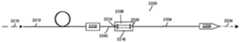
在其他示例中,设备包括光束耦合器,其被定位成接收输入光束并产生输出光束,其中,由光束耦合器限定的光学路径包括自由空间部分。VBC装置耦合到光束耦合器,并且包括输入光纤、扰动组件和输出光纤,其中,输入光纤光学耦合到输出光纤。扰动组件耦合到输入光纤和输出光纤中的至少一个,以修改从光束耦合器接收的输出光束的一个或多个光束特性,使得输出光纤传送经修改的光束。输出光纤具有保持由扰动组件修改的一个或多个光束特性的至少一部分的折射率轮廓。在一些示例中,输入光纤的折射率轮廓(RIP)不同于输出光纤的RIP。在一些实施例中,光束耦合器包括至少一个透镜,该透镜被定位成将由光束耦合器产生的输出光束引导至VBC装置的输入光纤。在其他示例中,光束耦合器的至少一个透镜包括第一透镜和第二透镜。第一透镜被定位成接收非导向输入光束并将准直光束传送到第二透镜,第二透镜被定位成将准直光束聚焦到VBC装置的输入光纤。In other examples, the apparatus includes a beam coupler positioned to receive an input beam and generate an output beam, wherein the optical path defined by the beam coupler includes a free space portion. The VBC device is coupled to the beam coupler and includes an input fiber, a perturbation assembly, and an output fiber, wherein the input fiber is optically coupled to the output fiber. A perturbation component is coupled to at least one of the input fiber and the output fiber to modify one or more beam characteristics of the output beam received from the beam coupler such that the output fiber transmits the modified beam. The output fiber has a refractive index profile that preserves at least a portion of the one or more beam properties modified by the perturbation component. In some examples, the refractive index profile (RIP) of the input fiber is different from the RIP of the output fiber. In some embodiments, the beam coupler includes at least one lens positioned to direct the output beam generated by the beam coupler to the input fiber of the VBC device. In other examples, the at least one lens of the beam coupler includes a first lens and a second lens. The first lens is positioned to receive the unguided input beam and transmit the collimated beam to a second lens positioned to focus the collimated beam to the input fiber of the VBC device.
根据一些示例,光束耦合器包括光纤-光纤耦合器(FFC),该光纤-光纤耦合器包括至少一个透镜,该透镜被定位成接收来自光纤的光束并将来自光纤的光束引导至VBC装置的输入光纤。FFC的至少一个透镜包括第一透镜和第二透镜。第一透镜被定位成接收来自光纤的光束并将准直光束传送到第二透镜,第二透镜被定位成将准直光束聚焦到VBC装置的输入光纤。在进一步的示例中,光束传送光纤被耦合以将来自光束耦合器的输出光束提供给VBC装置的输入光纤。通常,光束传送光纤的RIP不同于VBC装置的输入光纤和输出光纤的RIP。在一些示例中,一个或多个光束特性包括光束直径、发散度分布、光束参数积(BPP)、强度分布、亮度、M2值、数值孔径(NA)、光强度、功率密度、径向光束位置、辐射率或光斑尺寸或者其任意组合。According to some examples, the beam coupler includes a fiber-fiber coupler (FFC) including at least one lens positioned to receive and direct the beam from the fiber to an input of the VBC device optical fiber. At least one lens of the FFC includes a first lens and a second lens. The first lens is positioned to receive the light beam from the fiber and transmit the collimated light beam to the second lens, which is positioned to focus the collimated light beam to the input fiber of the VBC device. In a further example, a beam delivery fiber is coupled to provide the output beam from the beam coupler to the input fiber of the VBC device. In general, the RIP of the beam delivery fiber is different from the RIP of the input fiber and output fiber of the VBC device. In some examples, the one or more beam characteristics include beam diameter, divergence distribution, beam parameter product (BPP), intensity distribution, luminance, M value, numerical aperture( NA), light intensity, power density, radial beam position, emissivity or spot size or any combination thereof.
代表性方法包括:接收输入光束并允许输入光束作为非导向光束传播;并且将传播的非导向光束耦合到具有第一RIP的第一长度光纤。通过扰动第一长度光纤来修改耦合到第一长度光纤的光束的一个或多个光束特性。将经修改的光束从第一长度光纤耦合到具有第二RIP的第二长度光纤,该第二RIP被形成为在一个或多个第一限制区域内保持经修改的一个或多个光束特性的至少一部分,其中,第一RIP和第二RIP不同。在一些实施例中,从光纤接收输入光束,并且用透镜聚焦到第一长度光纤。在其他示例中,输入光束是用透镜聚焦到第一长度光纤的非导向光束。在另外的示例中,输入光束是用第一透镜准直并且用第二透镜聚焦到第一长度光纤的非导向光束。A representative method includes: receiving an input beam and allowing the input beam to propagate as an unguided beam; and coupling the propagated unguided beam to a first length of fiber having a first RIP. One or more beam properties of the light beam coupled to the first length of fiber are modified by perturbing the first length of fiber. Coupling the modified beam from the first length of fiber to a second length of fiber having a second RIP formed to maintain the modified one or more beam characteristics within the one or more first confinement regions At least a portion of wherein the first RIP and the second RIP are different. In some embodiments, an input light beam is received from an optical fiber and focused onto a first length of optical fiber with a lens. In other examples, the input beam is an unguided beam focused by a lens onto the first length of fiber. In another example, the input beam is an unguided beam collimated with a first lens and focused onto a first length of fiber with a second lens.
在又一些示例中,设备包括光束传送系统,其被光学耦合以接收激光束,其中,光束传送系统包括:输入光纤;输出光纤,其被光学耦合到输入光纤;以及扰动组件,其耦合到输入光纤和输出光纤中的至少一个,以修改接收的激光束的一个或多个光束特性,并从输出光纤传送经修改的激光束。输入光纤和输出光纤具有不同的RIP,并且光束传送系统限定包括自由空间部分的光学路径。在一些示例中,FFC被定位成接收激光束并将激光束耦合到输入光纤,其中,FFC限定光学路径的自由空间部分。在其他示例中,激光输入光纤被定位成接收激光束并将激光束耦合到FFC。在另外的示例中,光束传送光纤光学耦合到输出光纤,输入光纤、输出光纤和光束传送光纤具有不同的RIP。根据一些示例,光纤-光纤光学开关被定位成使得输入光纤可切换地耦合,以接收来自激光器的激光束,并且光学路径的自由空间部分由光纤-光纤光学开关限定。在进一步的示例中,激光器被定位成在激光输出光纤处提供激光束,并且光束传送系统包括被定位成接收来自激光器的激光束的FFC。FFC包括被定位成准直来自激光输出光纤的激光束的第一透镜和被定位成将准直的激光束引导至输入光纤的第二透镜,其中,激光输出光纤的RIP不同于输入光纤的RIP。在一些实施例中,第一透镜的焦距不同于第二透镜的焦距。In yet other examples, the apparatus includes a beam delivery system optically coupled to receive the laser beam, wherein the beam delivery system includes: an input fiber; an output fiber optically coupled to the input fiber; and a perturbation component coupled to the input at least one of an optical fiber and an output optical fiber to modify one or more beam characteristics of the received laser beam and transmit the modified laser beam from the output optical fiber. The input and output fibers have different RIPs, and the beam delivery system defines an optical path that includes a free-space portion. In some examples, the FFC is positioned to receive and couple the laser beam to the input fiber, wherein the FFC defines the free space portion of the optical path. In other examples, the laser input fiber is positioned to receive and couple the laser beam to the FFC. In another example, the beam delivery fiber is optically coupled to the output fiber, and the input fiber, output fiber, and beam delivery fiber have different RIPs. According to some examples, the fiber-to-fiber optical switch is positioned such that the input fiber is switchably coupled to receive the laser beam from the laser, and the free-space portion of the optical path is defined by the fiber-to-fiber optical switch. In a further example, the laser is positioned to provide a laser beam at a laser output fiber, and the beam delivery system includes an FFC positioned to receive the laser beam from the laser. The FFC includes a first lens positioned to collimate the laser beam from the laser output fiber, and a second lens positioned to direct the collimated laser beam to the input fiber, wherein the RIP of the laser output fiber is different from the RIP of the input fiber . In some embodiments, the focal length of the first lens is different from the focal length of the second lens.
附图说明Description of drawings
附图中相同的附图标记表示相同的元件,这些附图包含在本说明书中并构成本说明书的一部分,并且与说明书一起解释当前公开的技术的优点和原理。在附图中,Like reference numerals refer to like elements in the accompanying drawings, which are incorporated in and constitute a part of this specification, and together with the description, explain the advantages and principles of the presently disclosed technology. In the attached drawings,
图1示出用于提供具有可变光束特性的激光束的示例性光纤结构;FIG. 1 shows an exemplary fiber structure for providing a laser beam with variable beam characteristics;
图2绘示出用于传送具有可变光束特性的光束的示例性光纤结构的截面图;2 depicts a cross-sectional view of an exemplary fiber structure for delivering a beam with variable beam characteristics;
图3示出扰动用于提供具有可变光束特性的光束的光纤结构的示例方法;3 illustrates an example method of perturbing a fiber structure for providing a beam with variable beam characteristics;
图4是示出针对不同光纤弯曲半径的第一长度光纤计算的最低阶模式(LP01)的空间轮廓的曲线图;4 is a graph showing the spatial profile of the lowest order mode (LP01 ) calculated for a first length of fiber for different fiber bend radii;
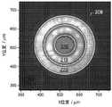
图5示出当用于改变光束特性的光纤几乎笔直时在结点(junction)处的二维强度分布的示例;Figure 5 shows an example of a two-dimensional intensity distribution at a junction when the optical fiber used to change the beam properties is nearly straight;
图6示出当用于改变光束特性的光纤以所选择的半径弯曲以优先激励第二长度光纤的具体限制区域时在结点处的二维强度分布的示例;FIG. 6 shows an example of a two-dimensional intensity distribution at a junction when the fiber used to modify the beam characteristics is bent at a radius selected to preferentially excite a specific confinement region of the second length of fiber;
图7-10绘示出实验结果,以示出用于改变图2所示的光束特性的光纤的各种弯曲半径的另外的输出光束;Figures 7-10 depict experimental results to illustrate additional output beams for various bend radii of the optical fibers used to vary the beam characteristics shown in Figure 2;
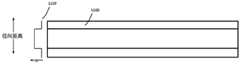
图11-16示出用于实现光纤组件中的光束特性调整的示例性第一长度光纤的截面图;Figures 11-16 illustrate cross-sectional views of an exemplary first length of optical fiber for enabling beam property adjustment in a fiber optic assembly;
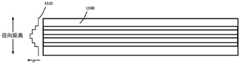
图17-19示出用于限制光纤组件中的经调整的光束特性的示例性第二长度光纤(“限制光纤”)的截面图;17-19 illustrate cross-sectional views of an exemplary second length of optical fiber ("confining fiber") for confinement of adjusted beam characteristics in a fiber optic assembly;
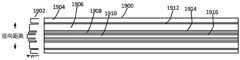
图20和21示出用于改变光纤组件中的经调整的光束的发散角并在光纤组件中限制经调整的光束的示例性第二长度光纤的截面图,该光纤组件被配置为提供可变光束特性;20 and 21 illustrate cross-sectional views of an exemplary second length fiber for varying the divergence angle of and confining the adjusted light beam in a fiber optic assembly configured to provide variable beam characteristics;
图22A示出包括光纤组件的示例性激光系统,该光纤组件被配置为提供位于馈送光纤和加工头之间的可变光束特性;22A illustrates an exemplary laser system including a fiber optic assembly configured to provide variable beam characteristics between a feed fiber and a processing head;
图22B示出包括光纤组件的示例性激光系统,该光纤组件被配置为提供位于馈送光纤和加工头之间的可变光束特性;22B illustrates an exemplary laser system including a fiber optic assembly configured to provide variable beam characteristics between a feed fiber and a processing head;
图23示出包括光纤组件的示例性激光系统,该光纤组件被配置为提供位于馈送光纤和多个加工光纤之间的可变光束特性;23 illustrates an exemplary laser system including a fiber optic assembly configured to provide variable beam characteristics between a feed fiber and a plurality of processing fibers;
图24示出根据本文提供的各种示例的用于提供可变光束特性的各种扰动组件的示例;24 illustrates examples of various perturbation components for providing variable beam characteristics according to various examples provided herein;
图25示出用于调整和保持光束的经修改的特性的示例性过程;FIG. 25 illustrates an exemplary process for adjusting and maintaining the modified characteristics of a light beam;
图26-28是示出用于限制光纤组件中的经调整的光束特性的示例性第二长度光纤(“限制光纤”)的截面图;26-28 are cross-sectional views illustrating an exemplary second length of optical fiber ("confining fiber") used to confine adjusted beam characteristics in a fiber optic assembly;
图29示出了具有拼接到光束修改系统的输入光纤的输出光纤的激光系统;Figure 29 shows a laser system with an output fiber spliced to an input fiber of a beam modification system;
图30示出了具有通过光纤-光纤耦合器(FFC)耦合到光束修改系统的输入光纤的输出光纤的激光系统;30 shows a laser system with an output fiber coupled to an input fiber of a beam modification system through a fiber-fiber coupler (FFC);
图31示出了包括将激光输出光束耦合到光束修改系统的FFC和将形状修改的光束传送到一个或多个选定的目标区域的光学系统的激光加工系统;31 illustrates a laser processing system including an FFC that couples a laser output beam to a beam modification system and an optical system that delivers the shape-modified beam to one or more selected target areas;
图32示出了具有拼接到具有串联的输入光纤的光束修改系统的输出光纤的激光系统;Figure 32 shows a laser system with output fibers spliced to a beam modification system with input fibers in series;
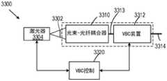
图33示出了激光系统,其中,非导向激光束耦合到VBC装置;Figure 33 shows a laser system with an unguided laser beam coupled to a VBC device;
图34示出了激光系统,其中,激光器耦合到FFC,然后该FFC耦合到VBC装置;Figure 34 shows a laser system where the laser is coupled to an FFC which is then coupled to a VBC device;
图35示出了包括选择性地将激光束耦合到一个或多个VBC装置的光纤-光纤开关的激光系统;35 shows a laser system including a fiber-to-fiber switch that selectively couples a laser beam to one or more VBC devices;
图36示出了可选的激光系统,其中,非导向激光束耦合到VBC装置。Figure 36 shows an alternative laser system in which an unguided laser beam is coupled to a VBC device.
具体实施方式Detailed ways
如整个本公开和权利要求中所使用的,单数形式“一”、“一个”和“该(所述)”包括复数形式,除非上下文另有明确规定。另外,术语“包含”是指“包括”。此外,术语“耦合(联接)”不排除在耦合(联接)的物项之间存在中间元件。此外,术语“修改”和“调整”可互换使用,表示“改变”。As used throughout this disclosure and the claims, the singular forms "a," "an," and "the (the)" include plural referents unless the context clearly dictates otherwise. Additionally, the term "comprising" means "including." Furthermore, the term "coupled (coupled)" does not exclude the presence of intervening elements between coupled (coupled) items. Also, the terms "modify" and "adjust" are used interchangeably to mean "change."
本文描述的系统、设备和方法不应被解释为以任何方式进行限制。相反,本公开单独以及以彼此的各种组合和子组合涉及各种公开的实施例的所有新颖和非显而易见的特征和方面。所公开的系统、方法和设备不限于任何特定方面或特征或其组合,所公开的系统、方法和设备也不要求存在任何一个或多个特定的优点或解决问题。任何操作理论都是为了便于解释,但是所公开的系统、方法和设备不限于这些操作理论。The systems, devices, and methods described herein should not be construed as limiting in any way. Rather, the present disclosure addresses all novel and non-obvious features and aspects of the various disclosed embodiments individually and in various combinations and subcombinations with each other. The disclosed systems, methods, and apparatus are not limited to any particular aspect or feature, or combination thereof, nor do the disclosed systems, methods, and apparatus require any one or more particular advantages or problems to be solved. Any theory of operation is provided for ease of explanation, but the disclosed systems, methods and apparatus are not limited to these theories of operation.
尽管为了方便呈现,以特定的顺序描述了一些公开的方法的操作,但是应该理解,这种描述方式包括重新排列,除非下面陈述的特定语言需要特定的顺序。例如,依次描述的操作在某些情况下可以重新排列或同时执行。此外,为了简单起见,附图可能没有示出所公开的系统、方法和设备可以与其他系统、方法和设备结合使用的各种方式。此外,本说明书有时使用诸如“生产”和“提供”等术语来描述所公开的方法。这些术语是所执行的实际操作的高级抽象。对应于这些术语的实际操作将根据具体的实现方式而变化,并且本领域普通技术人员容易辨别。Although the operations of some of the disclosed methods have been described in a specific order for ease of presentation, it should be understood that this manner of description includes rearrangements unless a specific order is required by the specific language set forth below. For example, operations described in sequence may in some cases be rearranged or performed concurrently. Furthermore, for the sake of simplicity, the figures may not illustrate the various ways in which the disclosed systems, methods, and devices may be used in conjunction with other systems, methods, and devices. Furthermore, this specification sometimes uses terms such as "producing" and "providing" to describe the disclosed methods. These terms are a high-level abstraction of the actual operation performed. The actual operation corresponding to these terms will vary depending on the particular implementation and will be readily discernible by those of ordinary skill in the art.
在一些示例中,值、过程或设备称为“最低”、“最佳”、“最小”等。应当理解,这样的描述旨在指示可以在所使用的许多功能替换中进行选择,并且这样的选择不需要比其他选择更好、更小或更优。参照指示为“上方”、“下方”、“上部”、“下部”等的方向来描述示例。这些术语用于方便描述,但并不意味着任何特定的空间方向。In some examples, a value, process, or device is referred to as "lowest," "optimal," "minimum," and the like. It should be understood that such descriptions are intended to indicate that a choice may be made among the many functional alternatives that may be employed, and that such choices need not be better, smaller, or superior to other choices. Examples are described with reference to directions indicated as "above," "below," "upper," "lower," and the like. These terms are used for convenience of description, but do not imply any particular spatial orientation.
定义definition
本文使用的词语和术语的定义:Definitions of words and terms used in this document:
1.术语“光束特性”表示用于描述光束的下列一个或多个术语。通常,最关注的光束特性取决于应用或光学系统的具体情况。1. The term "beam characteristics" means one or more of the following terms used to describe a light beam. In general, the beam characteristics of greatest interest depend on the specifics of the application or optical system.
2.术语“光束直径”被定义为沿着轴跨过光束中心的距离,对于该轴,辐照度(强度)等于最大辐照度的1/e2。虽然本文公开的示例通常使用以方位角对称模式传播的光束,但是可以使用椭圆或其他光束形状,并且光束直径可以沿着不同的轴而不同。圆形光束的特征在于单个光束直径。其他光束形状可以沿着不同的轴具有不同的光束直径。2. The term "beam diameter" is defined as the distance across the center of the beam along the axis for which the irradiance (intensity) is equal to 1/e2 of the maximum irradiance. While the examples disclosed herein generally use beams propagating in an azimuthally symmetric mode, elliptical or other beam shapes may be used, and beam diameters may vary along different axes. Circular beams are characterized by a single beam diameter. Other beam shapes can have different beam diameters along different axes.
3.术语“光斑尺寸”是从最大辐照度的中心点到1/e2点的径向距离(半径)。3. The term "spot size" is the radial distance (radius) from the center point of maximum irradiance to the 1/e2 point.
4.术语“光束发散度分布”是功率对全锥角。这个量有时称为“角度分布”或“NA分布”4. The term "beam divergence distribution" is power versus full cone angle. This quantity is sometimes called the "angular distribution" or "NA distribution"
5.术语激光束的“光束参数积”(BPP)定义为光束半径(在光束腰部处测量的)和光束发散度半角(在远场中测量的)的乘积。BPP的单位通常是mm-mrad。5. The term "beam parameter product" (BPP) of a laser beam is defined as the product of the beam radius (measured at the beam waist) and the beam divergence half angle (measured in the far field). The unit of BPP is usually mm-mrad.
6.“限制光纤”被定义为具有一个或多个限制区域的光纤,其中,限制区域包括被低折射率区域(包层区域)包围的高折射率区域(芯区域)。限制光纤的RIP可包括被低折射率区域(包层区域)包围的一个或多个高折射率区域(芯区域),其中,在高折射率区域中引导光。每个限制区域和每个包层区域可具有任何RIP,包括但不限于阶跃折射率和梯度折射率。限制区域可以是同心的,也可以不是同心的,并且可以是各种形状,例如,圆形、环形、多边形、弓形、椭圆形或不规则形等或者其任意组合。特定限制光纤中的限制区域可以都具有相同的形状或者可以是不同的形状。此外,限制区域可以是同轴的或者可以具有相对于彼此偏移的轴。限制区域可围绕中心轴线在纵向上具有均匀的厚度,或者厚度可以围绕中心轴线在纵向上变化。6. A "confining fiber" is defined as an optical fiber having one or more confinement regions, wherein the confinement regions include high index regions (core regions) surrounded by low index regions (cladding regions). The RIP confining the fiber may include one or more high refractive index regions (core regions) surrounded by low refractive index regions (cladding regions), wherein light is guided in the high refractive index regions. Each confinement region and each cladding region can have any RIP including, but not limited to, step index and gradient index. The confinement regions may or may not be concentric, and may be of various shapes, such as circular, annular, polygonal, arcuate, elliptical, or irregular, etc., or any combination thereof. The confinement regions in a particular confinement fiber may all have the same shape or may be of different shapes. Furthermore, the confinement regions may be coaxial or may have axes that are offset relative to each other. The confinement region may have a uniform thickness longitudinally around the central axis, or the thickness may vary longitudinally around the central axis.
7.术语“强度分布”是指作为沿着线(一维(1D)轮廓)或在平面(二维(2D)轮廓)上的位置的函数的光强度。线或平面通常垂直于光的传播方向。这是一种数量属性。7. The term "intensity distribution" refers to light intensity as a function of position along a line (one-dimensional (1D) profile) or on a plane (two-dimensional (2D) profile). Lines or planes are generally perpendicular to the direction of light propagation. This is a quantitative property.
8.“亮度”是在给定方向上传播的光的每单位面积的发光强度的光度测量值。8. "Brightness" is a photometric measurement of the luminous intensity per unit area of light propagating in a given direction.
9.“M2因子”(也称为“光束质量因子”或“光束传播因子”)是用于量化激光束的光束质量的无量纲参数,M2=1是衍射受限光束,较大的M2值对应于较低的光束质量。M2等于BPP除以λ/π,其中,λ是光束的波长,单位为微米(如果BPP以mm-mrad为单位表示)。9. The "M2 factor" (also called "beam quality factor" or "beam propagation factor") is a dimensionless parameter used to quantify the beam quality of a laser beam,M2 =1 is a diffraction limited beam, the larger TheM2 value corresponds to a lower beam quality.M2 is equal to BPP divided by λ/π, where λ is the wavelength of the beam in microns (if BPP is expressed in mm-mrad).
10.术语光学系统的“数值孔径”或“NA”是无量纲数,表征系统可以接受或发射的光的角度范围。10. The term "numerical aperture" or "NA" of an optical system is a dimensionless number that characterizes the angular range of light that the system can accept or emit.
11.术语“光强度”不是官方(SI)单位,而是用来表示表面上的或穿过平面的单位面积的入射功率。11. The term "light intensity" is not an official (SI) unit, but is used to denote the incident power per unit area on a surface or through a plane.
12.术语“功率密度”是指每单位面积的光功率,尽管这也称为“光强度”。12. The term "power density" refers to optical power per unit area, although this is also referred to as "light intensity".
13.术语“径向光束位置”是指在垂直于光纤轴的方向上,相对于光纤芯的中心测量的光纤中的光束的位置。13. The term "radial beam position" refers to the position of the beam in the fiber, measured relative to the center of the fiber core, in a direction perpendicular to the fiber axis.
14.“辐射率”是光源(例如,激光器)的单位面积在给定方向上每单位立体角发射的辐射。辐射率可以通过改变光束强度分布和/或光束发散轮廓或分布来改变。改变激光束的辐射率轮廓的能力意味着改变BPP的能力。14. "Emissivity" is the radiation emitted per unit solid angle in a given direction per unit area of a light source (eg, a laser). The radiance can be changed by changing the beam intensity distribution and/or the beam divergence profile or distribution. The ability to change the radiance profile of the laser beam implies the ability to change the BPP.
15.术语“折射率轮廓”或“RIP”是指折射率,作为沿着垂直于光纤轴的线(1D)或在垂直于光纤轴的平面(2D)中的位置的函数。许多光纤是方位对称的,在这种情况下,任何方位角的1D RIP都是相同的。15. The term "refractive index profile" or "RIP" refers to the refractive index as a function of position along a line (1D) perpendicular to the fiber axis or in a plane (2D) perpendicular to the fiber axis. Many fibers are azimuthally symmetric, in which case the 1D RIP is the same for any azimuth.
16.“阶跃折射率光纤”具有在光纤芯内平坦(折射率与位置无关)的RIP。16. A "step index fiber" has a RIP that is flat (index independent of position) within the fiber core.
17.“梯度折射率光纤”具有这样的RIP,其中,折射率随着径向位置的增加(即,随着与光纤芯的中心的距离增加)而降低。17. A "graded index fiber" having a RIP in which the index of refraction decreases with increasing radial position (ie, with increasing distance from the center of the fiber core).
18.“抛物线折射率光纤”是梯度折射率光纤的一种特殊情况,其中,折射率随着与光纤芯的中心的距离的增加而二次方地降低。18. "Parabolic index fiber" is a special case of gradient index fiber in which the index of refraction decreases quadratically with increasing distance from the center of the fiber core.
19.“自由空间传播”和“非导向传播”用于指在通常是光束瑞利范围的5、10、20、100倍或更多倍的光学距离上传播而不受一个或多个波导(例如,光纤)的限制的光束。这种传播可以在光学介质中进行,例如,玻璃、熔融石英、半导体、空气、晶体材料或真空。19. "Free-space propagation" and "unguided propagation" are used to refer to propagation over optical distances typically 5, 10, 20, 100 or more times the Rayleigh range of a beam without being affected by one or more waveguides ( For example, optical fibers) confined beams. This propagation can take place in optical media such as glass, fused silica, semiconductors, air, crystalline materials or vacuum.
20.“准直光束”通常通过定位透镜或其它聚焦元件(例如,曲面镜、菲涅耳透镜或全息光学元件)来产生,使得与光束具有、将具有或看起来具有平面波前(例如,在高斯光束的焦点处或光纤的输出端)的位置的表观距离小于与焦距f的焦点相距的焦距f的10%、5%、2%、1%、0.5%、0.1%。20. A "collimated beam" is typically created by positioning a lens or other focusing element (eg, a curved mirror, a Fresnel lens, or a holographic optical element) such that the beam has, will have, or appears to have a plane wavefront (eg, at The apparent distance at the focal point of the Gaussian beam or the output end of the fiber) is less than 10%, 5%, 2%, 1%, 0.5%, 0.1% of the focal length f from the focal point of the focal length f.
21.“光学路径”是指光束在穿过包括光学元件之间的空间的光学系统时所采用的路径。光学路径长度与光学路径的实际长度相关,但也包括与位于光学路径上的任何光学介质的折射率相关的贡献。21. "Optical path" refers to the path taken by a light beam as it travels through an optical system that includes spaces between optical elements. Optical path length is related to the actual length of the optical path, but also includes contributions related to the refractive index of any optical medium lying on the optical path.
用于改变光束特性的光纤Fibers for changing beam properties
在本文公开了方法、系统和设备,其被配置为提供光纤,该光纤可操作以提供具有可变光束特性(VBC)的激光束,该可变光束特性可降低上述常规方法的成本、复杂性、光损耗或其他缺点。这种VBC光纤被配置为改变多种光束特性。可使用VBC光纤来控制这些光束特性,从而允许用户调整各种光束特性,以适应各种激光加工应用的特殊要求。例如,VBC光纤可用于调整:光束直径、光束发散度分布、BPP、强度分布、M2因子、NA、光强度、功率密度、径向光束位置、辐射率、光斑尺寸等,或其任意组合。Disclosed herein are methods, systems and apparatus configured to provide optical fibers operable to provide a laser beam with variable beam characteristics (VBC) that can reduce the cost, complexity of the conventional methods described above , optical loss or other disadvantages. This VBC fiber is configured to change a variety of beam properties. These beam characteristics can be controlled using VBC fibers, allowing the user to adjust various beam characteristics to suit the specific requirements of various laser processing applications. For example, VBC fibers can be used to adjust: beam diameter, beam divergence distribution, BPP, intensity distribution,M2 factor, NA, light intensity, power density, radial beam position, radiance, spot size, etc., or any combination thereof.
通常,所公开的技术需要将激光束耦合到光纤中,其中,可以通过多种方法中的任何一种方法扰动激光束和/或扰动第一长度光纤(例如,弯曲光纤或引入一个或多个其他扰动),并且在第二长度光纤中完全或部分地保持经调整的光束特性,来调整光纤中激光束的特性。第二长度光纤被特别配置为保持和/或进一步修改经调整的光束特性。在一些情况下,第二长度光纤通过将激光束传送到其最终用途(例如,材料加工)来保持经调整的光束特性。第一长度光纤和第二长度光纤可包括相同或不同的光纤。Generally, the disclosed techniques require coupling a laser beam into an optical fiber, where the laser beam and/or the first length of fiber can be perturbed by any of a variety of methods (eg, bending the fiber or introducing one or more other perturbations) and maintain the adjusted beam characteristics in whole or in part in the second length of fiber to adjust the characteristics of the laser beam in the fiber. The second length of fiber is specifically configured to maintain and/or further modify the adjusted beam characteristics. In some cases, the second length of fiber maintains the adjusted beam characteristics by delivering the laser beam to its end use (eg, material processing). The first length of optical fiber and the second length of optical fiber may comprise the same or different optical fibers.
所公开的技术与光纤激光器和光纤耦合激光器兼容。光纤耦合激光器通常经由具有阶跃折射率轮廓(RIP)的传送光纤传输输出,即,具有在光纤芯内的平坦或恒定的折射率。实际上,取决于光纤的设计,传送光纤的RIP可能不是完全平坦的。重要的参数是光纤的芯直径(dcore)和NA。芯直径通常在10-1000微米的范围内(尽管其他值也是可能的),NA通常在0.06-0.22的范围内(尽管其他值也是可能的)。来自激光器的传送光纤可以直接路由到加工头或工件,或者可以路由到光纤-光纤耦合器(FFC)或光纤-光纤开关(FFS),其将来自传送光纤的光学耦合到将光束传输到加工头或工件的加工光纤中。The disclosed technology is compatible with fiber lasers and fiber coupled lasers. Fiber-coupled lasers typically transmit output via a delivery fiber with a stepped index profile (RIP), ie, with a flat or constant index of refraction within the fiber core. In fact, depending on the design of the fiber, the RIP of the delivery fiber may not be completely flat. Important parameters are the core diameter (dcore ) and NA of the fiber. The core diameter is typically in the range of 10-1000 microns (although other values are possible) and the NA is typically in the range of 0.06-0.22 (although other values are possible). The delivery fiber from the laser can be routed directly to the processing head or workpiece, or it can be routed to a fiber-to-fiber coupler (FFC) or fiber-to-fiber switch (FFS), which couples the optics from the delivery fiber to deliver the beam to the processing head or in the processing fiber of the workpiece.
大多数材料加工工具(特别是那些高功率(>1kW)的材料加工工具)采用多模(MM)光纤,但一些材料加工工具采用单模(SM)光纤,该单模光纤位于dcore和NA范围的低端。SM光纤的光束特性由光纤参数唯一确定。然而,来自MM光纤的光束特性可能变化(单位到单位和/或根据激光功率和时间),这取决于来自耦合到光纤中的激光源的光束特性、光纤的发射或拼接条件、光纤RIP以及光纤的静态和动态几何形状(弯曲、盘绕、运动、微弯曲等)。对于SM和MM传送光纤,光束特性对于给定的材料加工任务来说可能不是最佳的,对于一系列任务来说也不太可能是最佳的,这促使人们希望能够系统地改变光束特性,以便为特定的加工任务进行定制或优化。Most material processing tools (especially those with high power (>1kW)) use multimode (MM) fiber, but some material processing tools use single mode (SM) fiber, which is located at the dcore and NA low end of the range. The beam characteristics of an SM fiber are uniquely determined by the fiber parameters. However, the beam characteristics from the MM fiber may vary (unit to unit and/or according to laser power and time) depending on the beam characteristics from the laser source coupled into the fiber, the launch or splicing conditions of the fiber, the fiber RIP, and the fiber of static and dynamic geometries (bending, coiling, moving, microbending, etc.). For SM and MM delivery fibers, beam characteristics may not be optimal for a given material processing task, nor are they likely to be optimal for a range of tasks, prompting the desire to be able to systematically change beam characteristics, for customization or optimization for specific machining tasks.
在一个示例中,VBC光纤可以具有第一长度和第二长度,并且可以被配置为作为光纤内装置插置在传送光纤和加工头之间,以提供光束特性所需的可调整性。为了能够调整光束,扰动装置和/或组件设置在VBC光纤附近和/或与VBC光纤耦合,并且负责扰动第一长度的光束,使得光束的特性在第一长度光纤中改变,并且随着光束在第二长度光纤中传播,保持或进一步改变改变后的特性。扰动的光束发射到第二长度的VBC光纤中,该光纤被配置为保持经调整的光束特性。第一长度光纤和第二长度光纤可以是相同或不同的光纤和/或第二长度光纤可包括限制光纤。由第二长度的VBC光纤保持的光束特性可包括以下任一项:光束直径、光束发散度分布、BPP、强度分布、亮度、M2因子、NA、光强度、功率密度、径向光束位置、辐射率、光斑尺寸等或者其任意组合。In one example, the VBC fiber may have a first length and a second length, and may be configured to be interposed between the delivery fiber and the processing head as an intra-fiber device to provide the desired adjustability of the beam characteristics. In order to be able to tune the light beam, a perturbation device and/or assembly is provided near and/or coupled to the VBC fiber and is responsible for perturbing the first length of the light beam such that the properties of the light beam change in the first length of fiber and as the light beam is in the first length of the fiber Propagated in the second length of fiber, the altered characteristics are maintained or further altered. The perturbed beam is launched into a second length of VBC fiber that is configured to maintain the adjusted beam characteristics. The first length of optical fiber and the second length of optical fiber may be the same or different optical fibers and/or the second length of optical fiber may comprise a confinement optical fiber. The beam characteristics maintained by thesecond length of VBC fiber may include any of the following: beam diameter, beam divergence distribution, BPP, intensity distribution, luminance, M factor, NA, light intensity, power density, radial beam position, Emissivity, spot size, etc. or any combination thereof.
图1示出了示例性VBC光纤100,其用于提供具有可变光束特性的激光束,而不需要使用自由空间光学器件来改变光束特性。VBC光纤100包括第一长度光纤104和第二长度光纤108。第一长度光纤104和第二长度光纤108可以是相同或不同的光纤,并且可以具有相同或不同的RIP。第一长度光纤104和第二长度光纤108可以通过接头连接在一起。第一长度光纤104和第二长度光纤108可以以其他方式耦合,可以间隔开,或者可以经由插入部件连接,例如,另一长度光纤、自由空间光学器件、胶、折射率匹配材料等或者其任意组合。FIG. 1 shows an
扰动装置110设置在扰动区域106附近和/或包围扰动区域106。扰动装置110可以是装置、组件、光纤内结构和/或其他特征。扰动装置110至少扰动第一长度光纤104或第二长度光纤108或其组合中的光束102,以便调整光束102的一个或多个光束特性。响应于扰动装置110的扰动,可以在第一长度光纤104或第二长度光纤108或其组合中发生光束102的调整。扰动区域106可以在各种宽度上延伸,并且可以延伸或不延伸到第二长度光纤108的一部分中。当光束102在VBC光纤100中传播时,扰动装置110可以物理地作用在VBC光纤100上,以扰动光纤并调整光束102的特性。或者,扰动装置110可以直接作用在光束102上,以改变其光束特性。在调整之后,被扰动光束112具有与光束102不同的光束特性,其将在第二长度光纤108中完全或部分地保持。在另一示例中,扰动装置110不需要设置在接头附近。此外,根本不需要接头,例如,VBC光纤100可以是单根光纤,第一长度光纤和第二长度光纤可以间隔开或者以小间隙固定(空气间隔或填充有光学材料,例如,光学胶或折射率匹配材料)。The
被扰动光束112发射到第二长度光纤108中,其中,随着被扰动光束112传播,被扰动光束112的特性很大程度上被保持或继续发展,从而在第二长度光纤108的输出端产生经调整的光束特性。在一个示例中,新的光束特性可包括经调整的强度分布。在一个示例中,改变的光束强度分布将保持在第二长度光纤108的各种结构上有界限的限制区域中。因此,可以将光束强度分布调整到针对特定激光加工任务优化的期望光束强度分布。通常,被扰动光束112的强度分布将随着其在第二长度光纤108中传播而发展,以填充限制区域,其中响应于第一长度光纤104中的条件和由扰动装置110引起的扰动,被扰动光束112发射到该限制区域中。此外,根据发射条件和光纤特性,随着光束在第二光纤中传播,角度分布可能演变。通常,光纤在很大程度上保持了输入发散度分布,但是如果输入发散度分布很窄和/或如果光纤具有扰乱发散度分布的不规则性或故意性特征,则可能加宽该分布。下文将更详细地描述第二长度光纤108的各种限制区域、扰动和光纤特征。光束102和112是概念上的抽象,旨在示出光束如何传播通过VBC光纤100,以提供可变的光束特性,并非旨在对特定光束的行为进行精确地模拟。The
VBC光纤100可通过多种方法制造,包括PCVD(等离子体化学气相沉积)、OVD(外部气相沉积)、VAD(气相轴向沉积)、MOCVD(金属-有机化学气相沉积)和/或DND(直接纳米颗粒沉积)。VBC光纤100可包括多种材料。例如,VBC光纤100可包括SiO2、掺杂有GeO2的SiO2、锗硅酸盐、五氧化二磷、磷硅酸盐、Al2O3、铝硅酸盐等或其任意组合。限制区域可由掺杂氟、硼等或其任意组合的包层来限定。其他掺杂剂可以添加到活性光纤中,包括稀土离子,例如,Er3+(铒)、Yb3+(镱)、Nd3+(钕)、Tm3+(铥)、Ho3+(钬)等或其任意组合。限制区域可由折射率低于氟或硼掺杂的限制区域的包层来限定。或者,VBC光纤100可包括光子晶体光纤或微结构光纤。The
VBC光纤100适用于各种光纤、光纤光学器件或光纤激光器装置中的任何一种,包括连续波和脉冲光纤激光器、圆盘激光器、固态激光器或二极管激光器(脉冲速率不受限制,除了物理限制以外)。此外,平面波导或其他类型波导(而不仅仅是光纤)中的实现方式都在所要求保护的技术范围内。The
图2绘示出用于调整光束的光束特性的示例性VBC光纤200的截面图。在一个示例中,VBC光纤200可以是加工光纤,因为可以将光束传送到加工头以用于材料加工。VBC光纤200包括在结点206处拼接到第二长度光纤208的第一长度光纤204。扰动组件210设置在结点206附近。扰动组件210可以是被配置为能够调整在VBC光纤200中传播的光束202的光束特性的各种装置中的任何一种。在一个示例中,扰动组件210可以是心轴和/或另一装置,其可以提供改变接头附近的VBC光纤200的弯曲半径和/或弯曲长度的方式。将在下面参照图24讨论扰动装置的其他示例。FIG. 2 depicts a cross-sectional view of an
在一个示例中,第一长度光纤204具有抛物线折射率RIP 212,如左RIP图所示。当光纤204是笔直的或接近笔直的时,光束202的大部分强度分布集中在光纤204的中心。第二长度光纤208是具有RIP 214的限制光纤,如右RIP图所示。第二长度光纤208包括限制区域216、218和220。限制区域216是由两个环形(或环状)限制区域218和220包围的中心芯。层222和224是通常称为“包层”区域的限制区域(216、218和220)之间的由低折射率材料构成的结构屏障。在一个示例中,层222和224可包括氟硅酸盐环;在一些实施例中,氟硅酸盐包层相对较薄。也可以使用其他材料,并且要求保护的主题不限于此。In one example, the first length of
在一个示例中,当光束202沿着VBC光纤200传播时,扰动组件210可以物理地作用在光纤208和/或光束202上,以调整其光束特性并生成经调整的光束226。在当前示例中,光束202的强度分布被扰动组件210修改。在调整光束202之后,经调整的光束226的强度分布可集中在外部限制区域218和220中,其中,在中心限制区域216中强度相对较小。因为限制区域216、218和/或220中的每一个被屏障层222和224中的较低折射率材料薄层隔离,所以第二长度光纤208可以基本上保持经调整的光束226的经调整的强度分布。光束通常会在给定的限制区域内以方位角分布,但是当沿着第二长度光纤208传播时,不会在限制区域之间(显著地)过渡。因此,经调整的光束226的经调整的光束特性在很大程度上保持在隔离的限制区域216、218和/或220内。在一些情况下,可能希望在限制区域216、218和/或220之间划分光束226的功率,而不是集中在单个区域中,并且这种条件可以通过生成适当的经调整的光束226来实现。In one example,
在一个示例中,芯限制区域216和环形限制区域218和220可以由熔融石英玻璃构成,并且限定限制区域的包层222和224可以由氟硅酸盐玻璃构成。其他材料可用于形成各种限制区域(216、218和220),包括锗硅酸盐、磷硅酸盐、铝硅酸盐等或其组合,并且要求保护的主题不限于此。其他材料可用于形成屏障环(222和224),包括熔融二氧化硅、硼硅酸盐等或其组合,并且要求保护的主题不限于此。在其他实施例中,光纤或波导包括或由各种聚合物或塑料或晶体材料组成。通常,芯限制区域的折射率大于相邻屏障/包层区域的折射率。In one example,
在一些示例中,可能希望增加第二长度光纤中的限制区域的数量,以增加在光束位移上的光束控制的粒度,从而微调光束轮廓。例如,限制区域可以被配置为提供逐步的光束位移。In some examples, it may be desirable to increase the number of confinement regions in the second length of fiber to increase the granularity of beam control over beam displacement, thereby fine-tuning the beam profile. For example, the confinement region may be configured to provide stepwise beam displacement.
图3示出扰动光纤200以提供光束的可变光束特性的示例性方法。改变光纤的弯曲半径可以改变光纤内的光束的径向光束位置、发散角和/或辐射率轮廓。VBC光纤200的弯曲半径可通过使用阶梯形心轴或锥体作为扰动组件210而围绕拼接结点206从第一弯曲半径R1减小到第二弯曲半径R2。另外或替代地,心轴或锥体上的接合长度可以变化。辊250可用于横跨扰动组件210与VBC光纤200接合。在一个示例中,辊250与光纤200的接合量已经显示为将强度轮廓的分布转移到具有固定心轴半径的光纤200的外部限制区域218和220。有多种其他方法用于改变光纤200的弯曲半径,例如,使用夹持组件、挠性管等或其组合,并且要求保护的主题不限于此。在另一示例中,对于特定的弯曲半径,VBC光纤200弯曲的长度也可以以可控和可再现的方式来改变光束特性。在示例中,改变弯曲半径和/或长度(光纤以特定的弯曲半径在该长度上弯曲)也修改了光束的强度分布,使得一个或多个模式可以径向地偏离光纤芯的中心。FIG. 3 illustrates an exemplary method of perturbing the
保持光纤在结点206上的弯曲半径,确保了经调整的光束特性(例如,光束202的径向光束位置和辐射率轮廓)在发射到第二长度光纤208之前不会返回到光束202的未扰动状态。此外,可基于VBC光纤200的弯曲半径和/或弯曲长度的减小程度来改变经调整的光束226的经调整的径向光束特性,包括位置、发散角和/或强度分布。因此,可以使用该方法获得特定的光束特性。Maintaining the bend radius of the fiber at the
在当前示例中,具有第一RIP 212的第一长度光纤204在结点206处拼接到具有第二RIP 214的第二长度光纤208。然而,可以使用具有单个RIP的单根光纤,该RIP形成为能够扰动(例如,通过微弯曲)光束202的光束特性,并且还能够保持经调整的光束。这种RIP可以类似于图17、18和/或19所示的光纤中所示的RIP。In the current example, a first length of
图7-10提供了VBC光纤200(如图2和3所示)的实验结果,并进一步示出当扰动组件210作用在VBC光纤200上以弯曲光纤时,对VBC光纤200的扰动的光束响应。图4-6是模拟,图7-10是实验结果,其中,来自SM 1050nm光源的光束发射到具有40微米的芯直径的输入光纤(未示出)中。输入光纤拼接到第一长度光纤204。FIGS. 7-10 provide experimental results of VBC fiber 200 (shown in FIGS. 2 and 3 ) and further illustrate the beam response to perturbation of
图4是示出不同光纤弯曲半径402的第一长度光纤204的最低阶模式(LP01)的计算轮廓的示例性图表400,其中,扰动组件210涉及弯曲VBC光纤200。随着光纤弯曲半径的减小,调整在VBC光纤200中传播的光束,使得模式径向地偏离VBC光纤200的芯的中心404(r=0微米),朝向芯/包层界面(在该示例中位于r=100微米处)。高阶模式(LPIn)也随着弯曲而偏移。因此,笔直的或接近笔直的光纤(非常大的弯曲半径),LP01的曲线406在VBC光纤200的中心或其附近居中。在大约6cm的弯曲半径处,LP01的曲线408从VBC光纤200的中心406偏移到大约40μm的径向位置。在大约5cm的弯曲半径处,LP01的曲线410从VBC光纤200的中心406偏移到大约50μm的径向位置。在大约4cm的弯曲半径处,LP01的曲线412从VBC光纤200的中心406偏移到大约60μm的径向位置。在大约3cm的弯曲半径处,LP01的曲线414从VBC光纤200的中心406偏移到大约80μm的径向位置。在大约2.5cm的弯曲半径处,LP01的曲线416从VBC光纤200的中心406偏移到大约85μm的径向位置。注意,模式的形状保持相对恒定(直到接近芯的边缘),这是抛物线RIP的特定属性。尽管在某些情况下,该属性可能是期望的,但VBC功能不需要该属性,并且可以使用其他RIP。FIG. 4 is an
在一个示例中,如果VBC光纤200被拉直,则LP01模式将移回光纤的中心。因此,第二长度光纤208的目的是将光束的经调整的强度分布“捕获”或限制在偏离VBC光纤200中心的限制区域中。光纤204和208之间的接头包括在弯曲区域中,因此移位的模式轮廓将优先发射到环形限制区域218和220中的一个中,或者分布在限制区域中。图5和6示出了这种效果。In one example, if the
图5示出了当VBC光纤200几乎笔直时,在第二长度光纤208内的结点206处的示例性二维强度分布。大部分LP01和LPIn在光纤208的限制区域216内。图6示出了当VBC光纤200以所选择的半径弯曲以优先激励第二长度光纤208的限制区域220(最外面的限制区域)时,在第二长度光纤208内的结点206处的二维强度分布。大部分LP01和LPIn在光纤208的限制区域220内。FIG. 5 shows an exemplary two-dimensional intensity distribution at
在一个示例中,第二长度光纤208的限制区域216具有100微米的直径,限制区域218的直径在120微米和200微米之间,限制区域220的直径在220微米和300微米之间。限制区域216、218和220由10μm厚的氟硅酸盐环隔开,从而为限制区域提供0.22的NA。可以采用限制区域的其他的内径和外径、分隔限制区域的环的厚度、限制区域的NA值以及限制区域的数量。In one example,
再次参考图5,利用所述参数,当VBC光纤200笔直时,大约90%的功率包含在中心限制区域216内,并且大约100%的功率包含在限制区域216和218内。现在参考图6,当光纤200弯曲以优先激励第二环形限制区域220时,接近75%的功率包含在限制区域220内,超过95%的功率包含在限制区域218和220内。这些计算包括LP01和两种高阶模式,这在一些2-4kW光纤激光器中是典型的。Referring again to FIG. 5, using the parameters, when the
从图5和图6可以清楚地看出,在扰动组件210作用在VBC光纤200上以弯曲光纤的情况下,弯曲半径确定了第一长度光纤204的模态强度分布与第二长度光纤208的不同引导限制区域(216、218和220)的空间重叠。因此,改变弯曲半径可以改变第二长度光纤208的输出端的强度分布,从而改变光束的直径或光斑尺寸,并因此还改变其辐射率和BPP值。可以在全光纤结构中实现光斑尺寸的这种调整,从而不涉及自由空间光学器件,因此可以减少或消除上述自由空间光学器件的缺点。这种调整也可以通过改变弯曲半径、弯曲长度、光纤张力、温度或下面讨论的其他扰动的其他扰动组件来进行。It can be clearly seen from FIGS. 5 and 6 that with the
在典型的材料加工系统(例如,切割或焊接工具)中,加工光纤的输出由加工头在工件处或附近成像。因此,改变如图5和6所示的强度分布能够改变工件处的光束轮廓,以便根据需要调整和/或优化工艺。出于上述计算的目的,假设了两种光纤的特定RIP,但是其他RIP也是可能的,并且所要求保护的主题不限于此。In a typical material processing system (eg, cutting or welding tool), the output of the processing fiber is imaged at or near the workpiece by a processing head. Thus, changing the intensity distribution as shown in Figures 5 and 6 can change the beam profile at the workpiece in order to adjust and/or optimize the process as needed. For the purposes of the above calculations, specific RIPs for both fibers are assumed, but other RIPs are possible, and the claimed subject matter is not so limited.
图7-10绘示出实验结果(测量的强度分布),以示出图2所示的VBC光纤200的各种弯曲半径的另外的输出光束。FIGS. 7-10 depict experimental results (measured intensity distributions) to illustrate additional output beams for various bend radii of the
在图7中,当VBC光纤200笔直时,光束几乎完全限于限制区域216。随着弯曲半径的减小,强度分布移动到更高的直径(图8-10)。图8绘示出当VBC光纤200的弯曲半径被选择为使强度分布优先向限制区域218移动时的强度分布。图9绘示出当弯曲半径进一步减小并被选择为使强度分布向外移动到限制区域220和限制区域218时的实验结果。在图10中,在最小弯曲半径时,光束几乎是“环形模式”,大部分强度在最外面的限制区域220中。In Figure 7, when the
尽管在拼接结点206处从一侧激励限制区域,但是由于光束在VBC光纤200内传播时限制区域内的加扰,强度分布在方位上是几乎对称的。虽然光束在传播时通常会在方位角上加扰,但是可以包括各种结构或扰动(例如,线圈),以促进这一过程。Although the confinement region is excited from one side at the
对于在图7-10所示的实验中使用的光纤参数,并不完全激励特定的限制区域,因为在多个限制区域中存在某种强度。该特征可以实现有利的材料加工应用,这些应用通过具有更平坦或分布的光束强度分布而被优化。在需要对给定限制区域进行更清洁的激励的应用中,可以采用不同的光纤RIP来实现这一特征。For the fiber parameters used in the experiments shown in Figures 7-10, a particular confinement region is not fully excited because a certain intensity exists in multiple confinement regions. This feature can enable advantageous material processing applications that are optimized by having a more flat or distributed beam intensity distribution. In applications that require cleaner excitation for a given confined area, different fiber RIPs can be employed to achieve this feature.
图7-10中所示的结果与本实验中使用的特定光纤有关,并且细节将根据实现方式的细节而变化。具体而言,输出光束的空间轮廓和发散度分布及其对弯曲半径的依赖性将取决于所采用的特定RIP、拼接参数以及发射到第一光纤中的激光源的特性。The results shown in Figures 7-10 are related to the specific fibers used in this experiment, and the details will vary depending on the implementation details. Specifically, the spatial profile and divergence distribution of the output beam and its dependence on bend radius will depend on the particular RIP employed, the splice parameters, and the characteristics of the laser source launched into the first fiber.
可以使用不同于图2所示的光纤参数,并且这些参数仍然在要求保护的主题的范围内。具体地,不同的RIP和芯尺寸和形状可用于促进与不同输入光束轮廓的兼容性,并实现不同的输出光束特性。除了图2所示的抛物线折射率轮廓之外,第一长度光纤的示例RIP还包括其他梯度折射率轮廓、阶跃折射率、基座设计(pedestal design)(即,随着距光纤中心距离的增加,折射率逐渐降低的嵌套芯)以及具有相同折射率值但中心芯和周围环具有不同NA值的嵌套芯的设计。除了图2所示的轮廓之外,第二长度光纤的示例RIP包括具有不同数量限制区域的限制光纤、非均匀限制区域厚度、包围限制区域的环的厚度的不同和/或非均匀的值、限制区域的不同和/或非均匀的NA值、RIP的高折射率和低折射率部分的不同折射率值、非圆形限制区域(例如,椭圆形、卵形、多边形、正方形、矩形或其组合)以及其他设计,如在图26-28中更详细讨论的。此外,本文描述的VBC光纤200和VBC光纤的其他示例不限于使用两根光纤。在一些示例中,实现方式可以包括使用一根光纤或两根以上的光纤。在某些情况下,光纤可能不是轴向均匀的;例如,可以包括光纤布拉格光栅或长周期光栅,或者直径可以沿着光纤的长度变化。此外,光纤不必是方位对称的,例如,芯可以具有正方形或多边形形状。可以使用各种光纤涂层(缓冲层),包括高折射率或折射率匹配涂层(其在玻璃-聚合物界面处剥离光)和低折射率涂层(其在玻璃-聚合物界面处通过全内反射引导光)。在一些示例中,可以在VBC光纤200上使用多个光纤涂层。Fiber parameters other than those shown in Figure 2 may be used and remain within the scope of the claimed subject matter. Specifically, different RIP and core sizes and shapes can be used to facilitate compatibility with different input beam profiles and achieve different output beam characteristics. In addition to the parabolic index profile shown in Figure 2, the example RIP for the first length of fiber includes other gradient index profiles, step index, pedestal designs (ie, with distance from the center of the fiber) increasing, gradually decreasing index of refraction) and designs of nested cores with the same index value but with different NA values for the central core and surrounding rings. In addition to the profiles shown in FIG. 2, example RIPs for the second length of fiber include confinement fibers with different numbers of confinement regions, non-uniform confinement region thicknesses, different and/or non-uniform values for the thickness of the rings surrounding the confinement regions, Different and/or non-uniform NA values for confinement regions, different refractive index values for high and low index portions of the RIP, non-circular confinement regions (e.g., elliptical, oval, polygonal, square, rectangular, or combination) and other designs, as discussed in more detail in Figures 26-28. Furthermore, the other examples of
图11-16示出了用于能够响应于在第一长度光纤中传播的光束的扰动来调整VBC光纤中的光束特性的第一长度光纤的示例的截面图。可以在第一长度光纤中调整的光束特性的一些示例是:光束直径、光束发散度分布、BPP、强度分布、亮度、M2因子、NA、光强度轮廓、功率密度轮廓、径向光束位置、辐射率、光斑尺寸等或者其任意组合。在图11-16中绘示的和下面描述的第一长度光纤仅仅是示例,并没有提供可用于调整VBC光纤组件中的光束特性的第一长度光纤的多样性的详尽叙述。图11-16所示的第一长度光纤的材料、合适的RIP和其他变量的选择至少取决于期望的光束输出。各种各样的光纤变量被考虑在内,并且在所要求保护的主题的范围内。因此,所要求保护的主题不受本文提供的示例的限制。11-16 illustrate cross-sectional views of examples of a first length of fiber capable of adjusting beam characteristics in a VBC fiber in response to perturbations of the beam propagating in the first length of fiber. Some examples of beam properties that can be adjusted in the first length of fiber are: beam diameter, beam divergence distribution, BPP, intensity distribution, brightness, Mfactor , NA, light intensity profile, power density profile, radial beam position, Emissivity, spot size, etc. or any combination thereof. The first lengths of fiber depicted in Figures 11-16 and described below are examples only and do not provide an exhaustive description of the variety of first lengths of fiber that can be used to adjust beam characteristics in a VBC fiber optic assembly. The choice of material, suitable RIP and other variables for the first length of fiber shown in Figures 11-16 depends at least on the desired beam output. A wide variety of fiber optic variables are contemplated and are within the scope of the claimed subject matter. Accordingly, the claimed subject matter is not limited by the examples provided herein.
在图11中,第一长度光纤1100包括阶跃折射率轮廓1102。图12示出了第一长度光纤1200,包括“基座RIP”(即,包括由较大阶跃折射率区域包围的阶跃折射率区域的芯)1202。图13示出了包括多基座RIP 1302的第一长度光纤1300。In FIG. 11 , the first length of
图14A示出了第一长度光纤1400,包括由下掺杂区域1404包围的梯度折射率轮廓1418。当扰动光纤1400时,模式可能在光纤1400中径向地向外移动(例如,在光纤1400弯曲期间)。梯度折射率轮廓1402可以被设计成促进保持或甚至压缩模态形状。这种设计可以促进调整在光纤1400中传播的光束,以生成光束强度分布集中在光纤的外周(即,在光纤芯的偏离光纤轴的一部分中)的光束。如上所述,当经调整的光束耦合到具有限制区域的第二长度光纤中时,经调整的光束的强度分布可被限于最外面的限制区域中,从而提供环形强度分布。具有窄外部限制区域的光束光斑可用于实现某些材料加工动作。FIG. 14A shows a first length of
图14B示出了第一长度光纤1406,包括由下掺杂区域1408包围的梯度折射率轮廓1414,类似于光纤1400。然而,光纤1406包括发散结构1410(低折射率区域),如轮廓1412所示。发散结构1410是由折射率比周围芯低的材料形成的区域。当光束发射到第一长度光纤1406中时,来自发散结构1410的折射导致光束发散度在第一长度光纤1406中增加。发散度的增加量取决于光束与发散结构1410的空间重叠量以及发散结构1410和芯材料之间的折射率差的大小。发散结构1410可以具有多种形状,这取决于输入发散度分布和期望的输出发散度分布。在一个示例中,发散结构1410具有三角形或梯度折射率形状。FIG. 14B shows a first length of
图15示出了第一长度光纤1500,包括由恒定折射率区域1504包围的抛物线折射率中心区域1502,并且恒定折射率区域1504由低折射率环形层1506包围。低折射率环1506有助于引导光束在光纤1500中传播。当扰动传播的光束时,模式在光纤1500中径向地向外移动(例如,在光纤1500弯曲期间)。当一个或多个模式径向地向外移动时,抛物线折射率区域1502促进保持模式形状。当模式到达RIP 1510的恒定折射率区域时,将在低折射率环1506上压缩,这可能导致第二光纤中最外面的限制区域的优先激励(与图14所示的第一光纤RIP相比)。在一种实现方式中,这种光纤设计与具有中心阶跃折射率芯和单个环形芯的限制光纤一起工作。RIP的抛物线折射率部分1502与限制光纤的中心阶跃折射率芯重叠。恒定折射率部分1504与限制光纤的环形芯重叠。第一光纤的恒定折射率部分1504旨在通过弯曲而使光束更容易移动到与环形芯重叠。这种光纤设计也适用于限制光纤的其他设计。15 shows a first length of
图16示出了第一长度光纤1600,包括由较低折射率层1610、1612和1614界定的引导区域1604、1606、1608和1616,其中,较低折射率层1610、1612和1614的折射率是阶梯形的,或者更一般地,不都具有相同的值。当扰动组件210(见图2)作用在光纤1600上时,阶梯折射率层可用于将光束强度限制在某些引导区域(1604、1606、1608和1616)。以这种方式,经调整的光束可以通过一系列扰动动作(例如,通过一系列弯曲半径、一系列弯曲长度、一系列微弯曲压力和/或一系列声光信号)被捕获在引导区域中,从而在光束强度分布移动到光纤1600中更远的径向位置之前,允许一定程度的扰动容限。因此,光束特性的变化可以逐步控制。可以调整引导区域1604、1606、1608和1616的径向宽度,以获得期望的环宽度,这是应用可能需要的。此外,如果需要,引导区域可以具有更厚的径向宽度,以便于捕获入射光束轮廓的更大部分。区域1606是这种设计的一个示例。16 shows a first length of
图17-21绘示出被配置为能够维持和/或限制第二长度光纤(例如,光纤208)中的经调整的光束特性的光纤的示例。这些光纤设计称为“环形限制光纤”,因为包含由环形或环状芯包围的中心芯。这些设计仅仅是示例,并不是对可用于维持和/或限制光纤内的经调整的光束特性的各种光纤RIP的详尽叙述。因此,要求保护的主题不限于本文提供的示例。此外,以上在图11-16中描述的任何第一长度光纤可以与图17-21描述的任何第二长度光纤组合。17-21 illustrate examples of fibers configured to maintain and/or limit the adjusted beam characteristics in a second length of fiber (eg, fiber 208). These fiber designs are referred to as "ring confined fibers" because they contain a central core surrounded by a toroidal or toroidal core. These designs are merely examples and are not intended to be an exhaustive description of the various fiber RIPs that can be used to maintain and/or limit the tuned beam characteristics within the fiber. Accordingly, the claimed subject matter is not limited to the examples provided herein. Furthermore, any of the first lengths of fibers described above in Figures 11-16 may be combined with any of the second lengths of fibers described in Figures 17-21.
图17示出了用于在VBC光纤组件中维持和/或限制经调整的光束特性的示例性第二长度光纤的截面图。当被扰动光束从第一长度光纤耦合到第二长度光纤1700时,第二长度光纤1700可以在一个或多个限制区域1704、1706和/或1708内保持响应于第一长度光纤中的扰动而调整的光束特性的至少一部分。光纤1700具有RIP 1702。限制区域1704、1706和/或1708中的每一个由较低折射率层1710和/或1712界定。这种设计使得第二长度光纤1700能够保持经调整的光束特性。结果,由光纤1700输出的光束将基本上保持所接收到的经调整的光束,如在第一长度光纤中修改的那样,从而给输出光束提供经调整的光束特性,这可以根据加工任务或其他应用定制。17 shows a cross-sectional view of an exemplary second length fiber for maintaining and/or confining adjusted beam characteristics in a VBC fiber optic assembly. When the perturbed light beam is coupled from the first length of fiber to the second length of
类似地,图18绘示出示例性第二长度光纤1800的截面图,用于维持和/或限制响应于VBC光纤组件中的第一长度光纤的扰动而调整的光束特性。光纤1800具有RIP 1802。然而,限制区域1808、1810和/或1812具有与限制区域1704、1706和1708不同的厚度。限制区域1808、1810和/或1812中的每一个由较低折射率层1804和/或1806界定。改变限制区域(和/或屏障区域)的厚度能够通过选择限制经调整的光束的特定径向位置来定制或优化所限制的经调整的辐射率轮廓。Similarly, FIG. 18 depicts a cross-sectional view of an exemplary second length of
图19绘示出具有RIP 1902的示例性第二长度光纤1900的截面图,用于维持和/或限制在VBC光纤组件中被配置为提供可变光束特性的经调整的光束。在该示例中,限制区域1904、1906、1908和1910的数量和厚度不同于光纤1700和1800,并且屏障层1912、1914和1916也具有不同的厚度。此外,限制区域1904、1906、1908和1910具有不同的折射率,屏障层1912、1914和1916也具有不同的折射率。这种设计可以进一步实现针对光纤1900内的特定径向位置进行限制和/或维持经调整的光束辐射的更精细或优化的定制。当扰动光束从第一长度光纤发射到第二长度光纤1900时,光束的经修改的光束特性(具有经调整的强度分布、径向位置和/或发散角等或其组合)被第二长度光纤1900的一个或多个限制区域1904、1906、1908和/或1910限制在特定半径内。19 depicts a cross-sectional view of an exemplary
如前所述,可以保持或调整光束的发散角,然后在第二长度光纤中保持。有多种方法可以改变光束的发散角。以下是光纤的示例,该光纤被配置为能够调整光纤组件中从第一长度光纤传播到第二长度光纤的光束的发散角,以改变光束特性。然而,这些仅仅是示例,并不是对可用于调整光束的发散度的各种方法的详尽叙述。因此,要求保护的主题不限于本文提供的示例。As before, the divergence angle of the beam can be maintained or adjusted and then maintained in the second length of fiber. There are various ways to change the divergence angle of the beam. The following is an example of an optical fiber configured to be able to adjust the divergence angle of a light beam propagating from a first length of fiber to a second length of fiber in a fiber optic assembly to change the beam characteristics. However, these are only examples and are not an exhaustive description of the various methods that can be used to adjust the divergence of a light beam. Accordingly, the claimed subject matter is not limited to the examples provided herein.
图20绘示出具有RIP 2002的示例性第二长度光纤2000的截面图,用于修改、维持和/或限制响应于第一长度光纤的扰动而调整的光束特性。在这个示例中,第二长度光纤2000类似于前面描述的第二长度光纤,并且形成VBC光纤组件的一部分,以用于传送可变光束特性,如上所述。具有三个限制区域2004、2006和2008以及三个屏障层2010、2012和2016。第二长度光纤2000还具有位于限制区域2006内的发散结构2014。发散结构2014是由折射率低于周围限制区域的材料形成的区域。当光束发射到第二长度光纤2000中时,来自发散结构2014的折射导致光束的发散度在第二长度光纤2000中增加。发散度的增加量取决于光束与发散结构2014的空间重叠量以及发散结构2014和芯材料之间的折射率差的大小。通过调整在发射到第二长度光纤2000的发射点附近的光束的径向位置,发散度分布可以改变。光束的经调整的发散度在光纤2000中保持,光纤2000被配置为将经调整的光束传送到加工头、另一光学系统(例如,光纤-光纤耦合器或光纤-光纤开关)、工件等或其组合。在一个示例中,发散结构2014可相对于周围材料具有约10-5-3x10-2的折射率下降。可以在本公开的范围内使用折射率下降的其他值,并且所要求保护的主题不限于此。20 depicts a cross-sectional view of an exemplary second length of
图21绘示出具有RIP 2102的示例性第二长度光纤2100的截面图,用于修改、维持和/或限制响应于第一长度光纤的扰动而调整的光束特性。第二长度光纤2100形成VBC光纤组件的一部分,以用于传送具有可变特性的光束。在该示例中,具有三个限制区域2104、2106和2108以及三个屏障层2110、2112和2116。第二长度光纤2100还具有多个发散结构2114和2118。发散结构2114和2118是由梯度低折射率材料形成的区域。当光束从第一长度光纤发射到第二长度光纤2100时,来自发散结构2114和2118的折射导致光束发散度增加。发散度的增加量取决于光束与发散结构的空间重叠量以及发散结构2114和/或2118分别与限制区域2106和2104的周围芯材料之间的折射率差的大小。通过调整在发射到第二长度光纤2100的发射点附近的光束的径向位置,发散度分布可以改变。图21所示的设计允许强度分布和发散度分布通过选择特定限制区域和该限制区域内的发散度分布而稍微独立地变化(因为每个限制区域可以包括发散结构)。光束的经调整的发散度在光纤2100中保持,光纤2100被配置为将经调整的光束传送到加工头、另一光学系统或工件。形成具有梯度或非恒定折射率的发散结构2114和2118使得能够调整在光纤2100中传播的光束的发散度轮廓。在由第二光纤传送到加工头时可以保持经调整的光束特性(例如,辐射率轮廓和/或发散度轮廓)。可替代地,当第二光纤通过光纤-光纤耦合器(FFC)和/或光纤-光纤开关(FFS)路由到将光束传送到加工头或工件的加工光纤时,可以保持或进一步调整经调整的光束特性,例如,辐射率轮廓和/或发散度轮廓。21 depicts a cross-sectional view of an exemplary second length of
图26-28是示出了光纤和光纤RIP的示例的截面图,该光纤和光纤RIP被配置为能够维持和/或限制在方位不对称的第二长度光纤中传播的光束的经调整的光束特性,其中,响应于耦合到第二长度光纤的第一长度光纤的扰动和/或扰动装置110对光束的扰动,来调整光束特性。这些方位上非对称的设计仅仅是示例,并不是对可用于维持和/或限制方位上非对称的光纤内的经调整的光束特性的各种光纤RIP的详尽叙述。因此,要求保护的主题不限于本文提供的示例。此外,各种第一长度光纤中的任何一种(例如,类似于上述的那些)可以与任何方位上非对称的第二长度光纤(例如,类似于图26-28中描述的那些)组合。26-28 are cross-sectional views illustrating examples of fibers and fiber RIPs configured to maintain and/or confine an adjusted beam of light propagating in the azimuthally asymmetric second length fiber characteristics, wherein the beam characteristics are adjusted in response to perturbation of the first length of optical fiber coupled to the second length of optical fiber and/or perturbation of the beam by
图26示出穿过椭圆光纤2600的横截面的不同方位角处的RIP。在第一方位角2602处,光纤2600具有第一RIP 2604。在从第一方位角2602旋转45o的第二方位角2606处,光纤2600具有第二RIP 2608。在从第二方位角2606旋转另一45o的第三方位角2610处,光纤2600具有第三RIP 2612。第一RIP 2604、第二RIP 2608和第三RIP2612都不同。FIG. 26 shows RIP at different azimuth angles through the cross-section of
图27示出穿过多芯光纤2700的横截面的不同方位角的RIP。在第一方位角2702处,光纤2700具有第一RIP 2704。在第二方位角2706处,光纤2700具有第二RIP 2708。第一RIP2704和第二RIP2708是不同的。在一个示例中,扰动装置110可以在多个平面中起作用,以便将经调整的光束发射到方位不对称的第二光纤的不同区域中。FIG. 27 shows RIP at different azimuth angles through a cross-section of a
图28示出穿过具有至少一个新月形芯的光纤2800的横截面的不同方位角处的RIP。在某些情况下,新月形的角可以是圆形、扁平的或其他形状,这可以最小化光学损失。在第一方位角2802处,光纤2800具有第一RIP 2804。在第二方位角2806处,光纤2800具有第二RIP 2808。第一RIP2804和第二RIP2808是不同的。Figure 28 shows RIP at different azimuths through a cross-section of an
图22A示出包括VBC光纤组件2202的激光系统2200的示例,VBC光纤组件2202被配置为提供可变光束特性。VBC光纤组件2202包括第一长度光纤104、第二长度光纤108和扰动装置110。VBC光纤组件2202设置在馈送光纤2212(即,来自激光源的输出光纤)和VBC传送光纤2240之间。VBC传送光纤2240可包括修改、维持和/或限制经调整的光束特性的第二长度光纤108或第二长度光纤108的延伸部分。光束2210经由馈送光纤2212耦合到VBC光纤组件2202中。光纤组件2202被配置为根据上述各种示例改变光束2210的特性。光纤组件2202的输出是经调整的光束2214,其耦合到VBC传送光纤2240中。VBC传送光纤2240将经调整的光束2214传送到自由空间光学组件2208,自由空间光学组件2208然后将光束2214耦合到加工光纤2204中。经调整的光束2214随后由加工光纤2204传送到加工头2206。加工头可以包括导波光学器件(例如,光纤和光纤耦合器)、自由空间光学器件(例如,透镜、反射镜、滤光器、衍射光栅)、光束扫描组件(例如,检流计扫描仪、多边形反射镜扫描仪)或用于对光束2214进行整形并将整形后的光束传送到工件的其他扫描系统。22A shows an example of a
在激光系统2200中,组件2208的一个或多个自由空间光学器件可以设置在FFC或其他光束耦合器2216中,以对经调整的光束2214(在图22A中以不同于光束2210的虚线表示)执行各种光学操作。例如,自由空间光学组件2208可保持光束2214的经调整的光束特性。加工光纤2204可具有与VBC传送光纤2240相同的RIP。因此,经调整的光束2214的经调整的光束特性可以一直保持到加工头2206。加工光纤2204可包括类似于上述任何第二长度光纤的RIP,包括限制区域。In the
FFC可以包括一个、两个或更多个透镜,但是在典型的示例中,使用两个透镜,在大多数实际示例中,两个透镜的焦距产生的放大率在0.8和1.2之间(即,透镜的焦距比在0.8和1.2之间),尽管其他值也是可能的并且有时使用其他值。The FFC may include one, two, or more lenses, but in typical examples two lenses are used, and in most practical examples, the focal lengths of the two lenses produce a magnification between 0.8 and 1.2 (ie, The focal length ratio of the lens is between 0.8 and 1.2), although other values are possible and sometimes used.
可替代地,如图22B所示,自由空间光学组件2208可以通过例如增加或减少光束2214的发散度和/或光斑尺寸(例如,通过放大或缩小光束2214)和/或以其他方式进一步修改经调整的光束2214,来改变光束2214的经调整的光束特性。此外,加工光纤2204可以具有与VBC传送光纤2240不同的RIP。因此,可以选择加工光纤2204的RIP,以保持由组件2208的自由空间光学器件对经调整的光束2214进行的附加调整,从而生成经两次调整的光束2224(在图22B中以不同于光束2214的虚线表示)。Alternatively, as shown in FIG. 22B, the free-
图23示出了激光系统2300的示例,其包括设置在馈送光纤2312和VBC传送光纤2340之间的VBC光纤组件2302。在操作期间,光束2310经由馈送光纤2312耦合到VBC光纤组件2302中。光纤组件2302包括第一长度光纤104、第二长度光纤108和扰动装置110,并被配置为根据上述各种示例改变光束2310的特性。光纤组件2302生成由VBC传送光纤2340输出的经调整的光束2314。VBC传送光纤2340包括第二长度光纤108,用于根据上述各种示例修改、维持和/或限制光纤组件2302中的经调整的光束特性(例如,参见图17-21)。VBC传送光纤2340将经调整的光束2314耦合到光束开关(FFS)2332中,该光束开关随后将其各种输出光束耦合到多个加工光纤2304、2320和2322中的一个或多个。加工光纤2304、2320和2322将经调整的光束2314、2328和2330传送到相应的加工头2306、2324和2326。23 shows an example of a
在一个示例中,光束开关2332包括一组或多组自由空间光学器件2308、2316和2318,其被配置为执行经调整的光束2314的各种光学操作。自由空间光学器件2308、2316和2318可以保持或改变光束2314的经调整的光束特性。因此,经调整的光束2314可由自由空间光学器件保持或进一步调整。加工光纤2304、2320和2322可以具有与VBC传送光纤2340相同或不同的RIP,这取决于是否希望保持或进一步修改从自由空间光学组件2308、2316和2318传送到相应加工光纤2304、2320和2322的光束。在其他示例中,光束2310的一个或多个光束部分耦合到工件,无需调整,或者不同的光束部分耦合到相应的VBC光纤组件,使得可以提供与多个光束特性相关联的光束部分,用于同时的工件加工。或者,光束2310可以切换到一组VBC光纤组件中的一个或多个。In one example,
通过自由空间光学组件2308、2316和2318中的任一个路由经调整的光束2314,使得能够将各种附加调整的光束传送到加工头2206、2324和2326。因此,激光系统2300提供附加的自由度来改变光束的特性,并且在加工头之间切换光束(“分时共享”)和/或同时将光束传送到多个加工头(“功率共享”)。The adjusted
例如,光束开关2332中的自由空间光学器件可以将经调整的光束2314引导至自由空间光学组件2316,该组件被配置为保持光束2314的经调整的特性。加工光纤2304可以具有与VBC传送光纤2340相同的RIP。因此,传送到加工头2306的光束将是所保持的经调整的光束2314。For example, free space optics in
在另一示例中,光束开关2332可以将经调整的光束2314引导至自由空间光学组件2318,该组件被配置为保持经调整的光束2314的经调整的特性。加工光纤2320可以具有不同于VBC传送光纤2340的RIP,并且可以配置在图20和21中所述的发散度改变结构,以对光束2314的发散度分布提供附加的调整。因此,传送到加工头2324的光束将是具有不同于经调整的光束2314的光束发散度轮廓的经两次调整的光束2328。In another example, the
加工光纤2304、2320和/或2322可以包括类似于上述任何第二长度光纤的RIP,包括限制区域或各种其他RIP,并且要求保护的主题不限于此。
在又一示例中,自由空间光学开关2332可以将经调整的光束2314引导至自由空间光学组件2308,该组件被配置为改变经调整的光束2314的光束特性。加工光纤2322可以具有不同于VBC传送光纤2340的RIP,并且可以被配置为保持(或者可替代地进一步修改)光束2314的新的进一步调整的特性。因此,传送到加工头2326的光束将是具有不同于经调整的光束2314的光束特性(由于经调整的发散度分布和/或强度分布)的经两次调整的光束2330。In yet another example, the free space
在图22A、22B和23中,FFC或FFS中的光学器件可以通过在发射到加工光纤中之前放大或缩小光束2214来调整空间轮廓和/或发散度轮廓。还可以经由其他光学变换来调整空间轮廓和/或发散度轮廓。也可以调整发射到加工光纤的发射位置。这些方法可以单独使用或组合使用。In Figures 22A, 22B and 23, the optics in the FFC or FFS can adjust the spatial profile and/or divergence profile by zooming in or out of the
图22A、22B和23仅仅提供了使用自由空间光学器件对光束特性的调整的组合和光纤RIP的各种组合的示例,以保持或修改经调整的光束2214和2314。上面提供的示例并非详尽的,仅用于说明目的。因此,所要求保护的主题不限于此。Figures 22A, 22B, and 23 merely provide examples of various combinations of combinations of beam characteristics and fiber RIP using free space optics to maintain or modify the adjusted
图24示出了根据本文提供的各种示例的用于扰动VBC光纤200和/或在VBC光纤200中传播的光束的扰动装置、组件或方法的各种示例(为了简单起见,在本文中统称为“扰动装置110”)。扰动装置110可以是各种装置、方法和/或组件中的任何一种,其被配置为能够调整在VBC光纤200中传播的光束的光束特性。在一个示例中,扰动装置110可以是心轴2402、VBC光纤中的微弯曲2404、挠性管2406、声光换能器2408、热装置2410、压电装置2412、光栅2414、夹具2416(或其他紧固件)等或其任意组合。这些仅仅是扰动装置100的示例,并不是扰动装置100的详尽列表,所要求保护的主题不限于此。24 illustrates various examples of perturbation devices, components, or methods for
心轴2402可用于通过提供VBC光纤200可弯曲的形式来扰动VBC光纤200。如上所述,减小VBC光纤200的弯曲半径,会径向地向外移动光束的强度分布。在一些示例中,心轴2402可以是阶梯形或圆锥形的,以提供离散的弯曲半径水平。可替代地,心轴2402可以包括没有阶梯的锥形,以提供连续的弯曲半径,从而更精确地控制弯曲半径。心轴2402的曲率半径可以是恒定的(例如,圆柱形)或非恒定的(例如,椭圆形)。类似地,挠性管2406、夹具2416(或其他种类的紧固件)或辊250可用于引导和控制VBC光纤200围绕心轴2402的弯曲。此外,改变光纤以特定弯曲半径弯曲的长度,也可以修改光束的强度分布。VBC光纤200和心轴2402可被配置为可预测地改变第一光纤内的强度分布(例如,与光纤弯曲的长度和/或弯曲半径成比例)。辊250可以沿着平台2434上的轨道2442上下移动,以改变VBC光纤200的弯曲半径。The
在具有或没有心轴2402的情况下,夹具2416(或其他紧固件)可用于引导和控制VBC光纤200的弯曲。夹具2416可以沿着轨道2442或平台2446上下移动。夹具2416也可以旋转,以改变VBC光纤200的弯曲半径、张力或方向。控制器2448可以控制夹具2416的移动。With or without the
在另一示例中,扰动装置110可以是挠性管2406,并且在具有或没有心轴2402的情况下,可以引导VBC光纤200弯曲。挠性管2406可以包围VBC光纤200。管2406可以由多种材料制成,并且可以使用由控制器2444控制的压电换能器来操纵。在另一示例中,夹具或其他紧固件可用于移动挠性管2406。In another example, the
VBC光纤中的微弯曲2404是由光纤上的侧向机械应力引起的局部扰动。微弯曲可引起模式耦合和/或从光纤内的一个限制区域过渡到另一限制区域,从而导致在VBC光纤200中传播的光束的不同光束特性。机械应力可由控制器2440控制的致动器2436施加。然而,这仅仅是在光纤200中引起机械应力的方法的一个示例,所要求保护的主题不限于此。
声光换能器(AOT)2408可用于使用声波诱发在VBC光纤中传播的光束的扰动。扰动是由声波的振荡机械压力修改光纤的折射率引起的。声波的周期和强度与声波的频率和振幅相关,从而允许对声波扰动进行动态控制。因此,包括AOT 2408的扰动组件110可以被配置为改变在光纤中传播的光束的光束特性。在一个示例中,压电换能器2418可以产生声波,并且可以由控制器或驱动器2420控制。可以调制AOT 2408中诱发的声波,以实时改变和/或控制VBC光纤200中光束的光束特性。然而,这仅仅是用于创建和控制AOT 2408的方法的示例,并且所要求保护的主题不限于此。An acousto-optic transducer (AOT) 2408 can be used to induce perturbations of a light beam propagating in a VBC fiber using sound waves. The perturbation is caused by the oscillating mechanical pressure of the acoustic wave modifying the refractive index of the fiber. The period and intensity of the sound waves are related to the frequency and amplitude of the sound waves, allowing dynamic control of the sound wave perturbations. Accordingly, the
热装置2410可用于使用热量诱发在VBC光纤中传播的光束的扰动。扰动是通过修改热量诱发的光纤的RIP引起的。扰动可以通过控制传送到光纤的热量和施加热量的长度来动态控制。因此,包括热装置2410的扰动组件110可以被配置为改变一系列的光束特性。热装置2410可由控制器2450控制。
压电换能器2412可用于使用压电作用诱发在VBC光纤中传播的光束的扰动。扰动是通过修改由连接到光纤的压电材料诱发的光纤的RIP引起的。裸光纤周围的护套形式的压电材料可以对光纤施加张力或压缩,从而经由所产生的密度变化来修改其折射率。扰动可以通过控制压电装置2412的电压来动态控制。因此,包括压电换能器2412的扰动组件110可以被配置为在特定范围内改变光束特性。
在一个示例中,压电换能器2412可以被配置为根据多种因素在多个方向(例如,轴向、径向和/或横向)上移动VBC光纤200,这些因素包括压电换能器2412如何连接到VBC光纤200、压电材料的极化方向、施加的电压等。另外,使用压电换能器2412可以弯曲VBC光纤200。例如,驱动具有包括相对电极的多个区段的一段长度的压电材料可导致压电换能器2412在侧向方向上弯曲。由电极2424施加到压电换能器2412的电压可以由控制器2422控制,以控制VBC光纤200的位移。可以调制位移,以实时改变和/或控制VBC光纤200中光束的光束特性。然而,这仅仅是使用压电换能器2412控制VBC光纤200的位移的方法的示例,并且所要求保护的主题不限于此。In one example, the
光栅2414可用于诱发在VBC光纤200中传播的光束的扰动。光栅2414可以通过将折射率的周期性变化记入芯内来写入光纤中。光栅2414(例如,光纤布拉格光栅)可以作为滤光器或反射器来操作。长周期光栅可以诱发在同向传播光纤模式之间的过渡。因此,可以使用长周期光栅来调整由一个或多个模式组成的光束的辐射率、强度轮廓和/或发散度轮廓,以将一个或多个原始模式耦合到具有不同辐射率和/或发散度轮廓的一个或多个不同模式。通过改变折射率光栅的周期或振幅来实现调整。例如,改变光纤布拉格光栅的温度、弯曲半径和/或长度(例如,拉伸)等方法可以用于这种调整。具有光栅2414的VBC光纤200可以联接到工作台2426。工作台2426可以被配置为执行多种功能中的任何一种,并且可以由控制器2428控制。例如,工作台2426可以用紧固件2430联接到VBC光纤200,并且可以被配置为使用紧固件2430来拉伸和/或弯曲VBC光纤200,以发挥杠杆作用。工作台2426可以具有嵌入式热装置,并且可以改变VBC光纤200的温度。The grating 2414 can be used to induce perturbations in the light beam propagating in the
图25示出了在不使用自由空间光学器件来调整光束特性的情况下,用于调整和/或保持光纤内的光束特性的示例过程2500。在方框2502中,扰动第一长度光纤和/或光束,以调整一个或多个光束特性。过程2500移动到方框2504,其中,将光束发射到第二长度光纤中。过程2500移动到方框2506,其中,具有经调整的光束特性的光束在第二长度光纤中传播。过程2500移动到方框2508,其中,在第二长度光纤的一个或多个限制区域内保持光束的一个或多个光束特性的至少一部分。第一长度光纤和第二长度光纤可以由相同的光纤组成,或者可以是不同的光纤。25 illustrates an example process 2500 for adjusting and/or maintaining beam properties within an optical fiber without using free space optics to adjust the beam properties. In
上述VBC装置可以耦合到任何光源,以便能够修改光束特性。因此,这种VBC装置与光源的最小变化相关联。例如,对于光纤耦合的二极管激光器、固态激光器或光纤激光器,不需要改变输出光纤、输出光连接器、操作软件和/或激光安全联锁系统。在高功率激光器的应用中,这种改变是极其复杂的。用于耦合高功率激光输出的光纤通常包括连接器(或连接器组件),该连接器相对于激光束精确定位并配备有冷却或保护材料。在某些情况下,承受高光功率的光纤接头需要保护,并且需要重新涂覆、灌封或其他保护措施。在其他情况下,监控接头和/或连接器,以评估散射或其他光功率水平,或利用一个或多个检测器、热敏电阻或其他装置确定连接器、光纤或接头温度。高功率系统还包括安全联锁装置,响应于输出光纤中的光功率而激活该安全联锁装置,并且对输出光纤的任何干扰都需要对安全联锁装置进行修改。最后,这种干扰会在激光系统的不同位置导致不安全的光功率,产生光学损坏,无效保证,或引起其他类型的安全问题,例如,火灾。The VBC device described above can be coupled to any light source in order to be able to modify the beam characteristics. Therefore, such a VBC arrangement is associated with minimal changes in the light source. For example, for fiber coupled diode lasers, solid state lasers, or fiber lasers, no changes to the output fiber, output optical connector, operating software, and/or laser safety interlock system are required. In high-power laser applications, this change is extremely complex. Optical fibers used to couple high power laser outputs typically include connectors (or connector assemblies) precisely positioned relative to the laser beam and equipped with cooling or protective materials. In some cases, fiber optic connectors that withstand high optical power require protection and require recoating, potting, or other protective measures. In other cases, splices and/or connectors are monitored to assess scatter or other optical power levels, or to determine connector, fiber, or splice temperature using one or more detectors, thermistors, or other devices. The high power system also includes a safety interlock that is activated in response to optical power in the output fiber, and any disturbance to the output fiber requires modification of the safety interlock. Ultimately, this interference can lead to unsafe optical power at various locations in the laser system, creating optical damage, voiding warranties, or causing other types of safety issues, such as fires.
参考图29,光学系统2900包括激光系统2901,激光系统2901包括将光束耦合到整体输出光纤2904的激光器2902。激光系统2901通常经由具有预定特性的输出光纤2904产生输出光束。如示意性示出的,输出光纤2904耦合到以下元件中的一个或多个:温度传感器2908,例如,热敏电阻(T);光电检测器(PD)2906,其被定位成检测光束在与输出光纤2904相关联的芯、包层、涂层或其他保护或屏蔽涂层或外壳中的一个或多个中传播的部分;或者温度控制装置2910,例如,散热器(HS)。光电探测器2906、温度传感器2908和散热器2910联接到控制器2911,控制器2911调节温度、光束功率,并且通常提供安全联锁,使得激光器2902响应于光电探测器2906检测到的不在对人员安全的范围内或者不在与激光器操作相关联的可靠性或损坏限度内的光功率而停用。光纤2904通常被定位成接收来自激光器2902的光束,以避免操作问题,并且优选由制造商耦合到激光器2902。光纤2904的扰动(例如,添加或移除光学连接器、光学拼接或缩短光纤2904)通常会导致足够大的操作差异,使得控制器2911不再能够检测潜在的不安全或破坏性操作条件,并且差异会导致触发安全联锁,使得激光系统2901停止产生光束。Referring to FIG. 29, an
如图29所示,激光系统2900包括光学接头2912,其将输出光纤2904耦合到第一光纤2914,第一光纤2914适于用作VBC装置2916的一部分。光学接头2912和第一光纤2914通常在激光器制造期间或工厂组装期间耦合到激光器2902。在一些情况下,光学接头2912和第一光纤2914不需要改变激光束空间轮廓,而是用于提供连接到包括扰动单元2918和第二光纤2920的VBC装置2916的适当连接。通常,VBC装置2916联接到控制器2911,使得用控制器2911选择调制或衰减。在其他示例中,手动控制VBC装置2916。As shown in FIG. 29 , the
如上所述,尽管如图29所示,光学接头可用于将高功率激光器耦合到VBC装置,但接头特性通常必须严格控制,以避免接头处的光学损伤、对激光器2902的背向反射,并避免不安全的光束泄漏。如果任何这样的接头特性倾向于导致这样的故障或危险状况,则控制器2911通常被配置成检测这种状况并适当地控制激光器2902。这种状况的检测通常需要输出光纤2904及其与激光器2902的耦合保持不受原始工厂设置的干扰。激光器2902、输出光纤2904或控制器2911提供的联锁响应于接头的安装而发生变化是不希望的,并且难以或不可能被激光系统用户满意地实现。因此,第一光纤2914到激光输出光纤2904的工厂安装(拼接)避免了在现场进行激光调整的需要。在替代示例中,激光输出光纤2904可以被选择为适合于随后的光束轮廓调整,但是由于对激光产生的可能影响,这种替换可能是不期望的。As noted above, although optical joints can be used to couple high power lasers to VBC devices as shown in Figure 29, joint characteristics must generally be tightly controlled to avoid optical damage at the joint, back reflections to the
利用拼接到激光器2902的合适光纤2914,用户可以根据需要相对于扰动组件2918和第二光纤2920定位第一光纤2914。第一光纤2914和输出光纤2904可以与熔接接头2912光学耦合(或者以其他方式光学耦合)。虽然这些附加的耦合会导致附加的复杂性,但是激光器2902的基本配置不会改变,并且控制器2911的热、光和其他监视和控制可以继续。然而,熔接接头2912通常必须由激光器制造商或供应商引入,以允许安全联锁和监控系统可靠地工作。在大多数实际示例中,用户在这种设置之外进行熔接拼接是不令人满意的。Using the
在图30所示的替代示例中,激光系统3000包括将激光束耦合到激光输出光纤3004的激光器3002。在这个示例中,光纤3004耦合到光电探测器3006和散热器3008,其温度可以用热敏电阻3010或其他热传感器来监控。在一些情况下,热电冷却器或其他冷却装置可以耦合到激光输出光纤3004。激光输出光纤3004终止于光学连接器3012。In the alternative example shown in FIG. 30 , the
FFC 3020在光学连接器3012中提供的光纤表面处光学耦合到激光输出光纤3004。FFC 3020包括透镜3022,其接收来自连接器3012的发散光束3024,并将会聚光束3026耦合到VBC装置3030的输入光纤3032中。透镜3022可以被定位成使得发散光束3024和会聚光束3026具有不同的光束数值孔径,以例如适应不同的光纤数值孔径。输入光纤3032光学耦合到输出光纤3034,并且光纤3032、3034中的至少一个耦合到扰动组件3038,扰动组件3038响应于来自控制器3040的控制信号在光束特性中产生扰动。扰动组件3038、输入光纤3032和输出光纤3034可以是上述任何实施例中的任何一种。通常,光纤3032、3034中的一个或两个的扰动施加在耦合部3036处或附近,例如,熔接接头、对接耦合部或邻近耦合部。The
FFC 3020允许VBC装置3030耦合到激光器3002,而不干扰激光器系统3000的传感器、联锁和光学控制。如上所述,激光输出光纤3004与VBC装置3030的输入光纤3032的直接耦合可能与加热、反射或其他操作变化相关联,这些变化对于高功率激光器通常是不期望的,并且难以适应,尤其是在用户安装时。The
图31示出了加工系统3100,其包括将加工光束耦合到光纤3104的激光器3102。包括透镜3108、3110的FFC 3106接收加工光束并将加工光束耦合到VBC装置3112的输入光纤3114。输出光纤3118被定位成接收来自界面区域3116的加工光束,并将成形的加工光束引导至激光加工光学器件3130。VBC装置3112包括可绕轴线3124旋转的滚筒3120。输入光纤3114和输出光纤3118中的一个或两个接触滚筒3120或以其他方式响应于滚筒3120的旋转而变形,以产生可变光束扰动。FIG. 31 shows a
成形光束被引导至激光加工光学器件3130,激光加工光学器件3130包括聚焦光学器件3132、附加的光束成形光学器件3134(例如,光束扩展器、变形透镜、变形棱镜或其他光学元件)以及将成形光束扫描到基板3140上的一个或多个位置的扫描仪3136。扫描仪3136可以包括一个或多个多边形反射镜、检流计、电光、声光或其他光束扫描系统或元件。基板3140通常由基板台3142保持,基板台3142可以改变基板3140相对于成形光束的位置。处理器控制器3150联接到激光器3102、VBC装置3112、激光加工光学器件3130和基板台3142,用于控制激光束功率、重复率、波长、脉冲长度、偏振状态、光束聚焦位置和尺寸、光束形状、扫描仪区域和速率、扫描位置的停留时间以及基板3140经由基板台的平移。在任何特定基板的加工过程中,可能需要这些参数中任何一个的多个值。例如,加工控制器3150可以联接到VBC装置3112,以针对不同的加工步骤产生不同尺寸和形状的光束,或者在一个或多个加工步骤期间改变光束形状和尺寸。The shaped beam is directed to
参考图32,激光加工系统3200包括具有激光器3204的激光系统3202,激光器3204被耦合以将光束引导至激光输出光纤3205中。光电二极管、热敏电阻、散热器或其他监控或保护装置3206被耦合到激光器3204或激光输出光纤3205,以提供例如安全联锁。激光输出光纤3205通过接头3208或光学连接器耦合到VBC装置3220的第一输入光纤3210。第一输入光纤3210被选择为具有与激光输出光纤3205基本相同的芯直径和数值孔径,并且可以基于激光输出光纤3205上安装的连接器来选择连接器。VBC装置3220还包括第二输入光纤3214,其通过接头3212或其他耦合器耦合到第一输入光纤3210。扰动装置3216与第二输入光纤3214和光束输出光纤3218中的至少一个接触或接近。控制器3230联接到VBC装置3220和激光系统3202。接头3212可以在受控设置中提供,并且第二输入光纤3212可以根据光束特性扰动的需要来选择,并且通常具有如上所述的RIP。Referring to FIG. 32, a
参考图33,激光系统3300包括激光器3304,激光器3304产生光束3302,光束3302被引导至光束-光纤耦合器3310,光束-光纤耦合器3310通常包括透镜,该透镜被定位成接收光束3202并将光束3202聚焦到VBC装置3312的输入光纤3313中。基于来自VBC控制器3320的控制信号,经由输出光纤3314输出具有优选光束特性的光束。这种设置倾向于减少VBC装置3312和其他组件与激光器3304的相互作用。参考图34,激光器3402将激光束引导至耦合到FFC 3406的光纤3404。FFC 3406对来自激光器3402的光束进行成形,以耦合到输出光纤3408。FFC 3406的输出光束通过输出光纤3408耦合到接头3410(或其他耦合部)和VBC装置3414的输入光纤3412。VBC装置3414的输出光纤3416将成形的输出光束耦合到具有由VBC装置3414控制的光束轮廓的目标或附加的光学器件。33, a
参考图35,激光器3502经由光纤3504将光束引导至光纤-光纤开关(FFS)3506。FFS3506包括可切换地耦合到透镜3509、3510、3511的输入透镜3508,透镜3509、3510、3511可以根据反射器3507的位置选择将光束或光束的一部分耦合到相应的光纤3513、3514、3515。如图35所示,VBC装置3518、3520耦合到光纤3513、3514,从而可以独立选择光束形状。在其他示例中,激光器3502不包括输出光纤,且自由空间或其他非导向光束可以引导至输入透镜3508。Referring to FIG. 35, a laser 3502 directs a beam of light to a fiber-fiber switch (FFS) 3506 via an optical fiber 3504. The
参考图36,激光系统3600包括激光器3604,激光器3604产生光束3602,将光束3602引导至光束-光纤耦合器3610,光束-光纤耦合器3610通常包括透镜,该透镜被定位成接收光束3602并将光束3602聚焦到第一光纤3611中,第一光纤3611通过光学接头3617耦合到VBC装置3612的输入光纤3613。基于来自光束控制器3620的控制信号,具有优选光束形状的光束经由输出光纤3614输出。这种设置倾向于减少VBC装置3612和其他组件与激光器3604的相互作用。36, a
利用上述配置,用于验证和建立安全或可靠的激光操作的控制和传感器部件(例如,耦合到激光输出连接器或输出光纤的部件)可以在连接到基于光纤的光束成形器时继续操作。With the above configuration, control and sensor components used to verify and establish safe or reliable laser operation (eg, components coupled to the laser output connector or output fiber) can continue to operate while connected to the fiber-based beam shaper.
已经描述和示出了当前公开的技术的示例的一般和特定原理,显而易见,在不脱离这些原理的情况下,可以在设置和细节上修改这些示例。我们要求在以下权利要求的精神和范围内的所有修改和变化。Having described and shown general and specific principles of examples of the presently disclosed technology, it will be evident that these examples may be modified in arrangement and detail without departing from these principles. We claim all modifications and variations within the spirit and scope of the following claims.
Claims (22)
Applications Claiming Priority (10)
| Application Number | Priority Date | Filing Date | Title |
|---|---|---|---|
| US201662401650P | 2016-09-29 | 2016-09-29 | |
| USPCT/US2017/034848 | 2017-05-26 | ||
| US15/607,399US10423015B2 (en) | 2016-09-29 | 2017-05-26 | Adjustable beam characteristics |
| US15/607,410 | 2017-05-26 | ||
| US15/607,410US10663767B2 (en) | 2016-09-29 | 2017-05-26 | Adjustable beam characteristics |
| US15/607,399 | 2017-05-26 | ||
| US15/607,411 | 2017-05-26 | ||
| US15/607,411US10295845B2 (en) | 2016-09-29 | 2017-05-26 | Adjustable beam characteristics |
| PCT/US2017/034848WO2018063452A1 (en) | 2016-09-29 | 2017-05-26 | Adjustable beam characteristics |
| PCT/US2018/024908WO2018217300A1 (en) | 2016-09-29 | 2018-03-28 | Fiber-couple device for varying beam characteristics |
Publications (2)
| Publication Number | Publication Date |
|---|---|
| CN110914728A CN110914728A (en) | 2020-03-24 |
| CN110914728Btrue CN110914728B (en) | 2022-05-27 |
Family
ID=59054235
Family Applications (11)
| Application Number | Title | Priority Date | Filing Date |
|---|---|---|---|
| CN201780060512.9AActiveCN109791252B (en) | 2016-09-29 | 2017-05-26 | Adjustable beam characteristics |
| CN201880048886.3AActiveCN110944787B (en) | 2016-09-29 | 2018-01-31 | Method and beam system for forming articles using variable beam parameters to control a melt pool |
| CN201880048577.6AExpired - Fee RelatedCN110959232B (en) | 2016-09-29 | 2018-03-16 | Optical modulator based on optical fiber |
| CN201880047416.5AActiveCN110892593B (en) | 2016-09-29 | 2018-03-28 | Optical fiber beam delivery device producing selectable intensity profiles |
| CN202310066799.3APendingCN115963601A (en) | 2016-09-29 | 2018-03-28 | Fiber Bending Mechanism |
| CN201880047650.8AActiveCN110914725B (en) | 2016-09-29 | 2018-03-28 | Optical fiber bending mechanism |
| CN202111497013.0AActiveCN114185176B (en) | 2016-09-29 | 2018-03-28 | Fiber optic beam delivery for selectable intensity profiles |
| CN201880047410.8AActiveCN110915078B (en) | 2016-09-29 | 2018-03-28 | System and method for modifying beam properties |
| CN201880047412.7AExpired - Fee RelatedCN110892304B (en) | 2016-09-29 | 2018-03-28 | Temporary apparent intensity profile generation by rapidly perturbing a variable beam characteristic fiber |
| CN201880047649.5AActiveCN110914728B (en) | 2016-09-29 | 2018-03-28 | Optical fiber coupling device for changing light beam characteristics |
| CN201880047422.0AActiveCN110914015B (en) | 2016-09-29 | 2018-03-28 | Method and system for material processing using a light beam |
Family Applications Before (9)
| Application Number | Title | Priority Date | Filing Date |
|---|---|---|---|
| CN201780060512.9AActiveCN109791252B (en) | 2016-09-29 | 2017-05-26 | Adjustable beam characteristics |
| CN201880048886.3AActiveCN110944787B (en) | 2016-09-29 | 2018-01-31 | Method and beam system for forming articles using variable beam parameters to control a melt pool |
| CN201880048577.6AExpired - Fee RelatedCN110959232B (en) | 2016-09-29 | 2018-03-16 | Optical modulator based on optical fiber |
| CN201880047416.5AActiveCN110892593B (en) | 2016-09-29 | 2018-03-28 | Optical fiber beam delivery device producing selectable intensity profiles |
| CN202310066799.3APendingCN115963601A (en) | 2016-09-29 | 2018-03-28 | Fiber Bending Mechanism |
| CN201880047650.8AActiveCN110914725B (en) | 2016-09-29 | 2018-03-28 | Optical fiber bending mechanism |
| CN202111497013.0AActiveCN114185176B (en) | 2016-09-29 | 2018-03-28 | Fiber optic beam delivery for selectable intensity profiles |
| CN201880047410.8AActiveCN110915078B (en) | 2016-09-29 | 2018-03-28 | System and method for modifying beam properties |
| CN201880047412.7AExpired - Fee RelatedCN110892304B (en) | 2016-09-29 | 2018-03-28 | Temporary apparent intensity profile generation by rapidly perturbing a variable beam characteristic fiber |
Family Applications After (1)
| Application Number | Title | Priority Date | Filing Date |
|---|---|---|---|
| CN201880047422.0AActiveCN110914015B (en) | 2016-09-29 | 2018-03-28 | Method and system for material processing using a light beam |
Country Status (7)
| Country | Link |
|---|---|
| US (9) | US10423015B2 (en) |
| EP (14) | EP3519871B1 (en) |
| JP (5) | JP7186695B2 (en) |
| KR (1) | KR102498030B1 (en) |
| CN (11) | CN109791252B (en) |
| TW (1) | TWI695196B (en) |
| WO (27) | WO2018063452A1 (en) |
Families Citing this family (91)
| Publication number | Priority date | Publication date | Assignee | Title |
|---|---|---|---|---|
| JP6349410B2 (en) | 2014-02-26 | 2018-06-27 | ビエン チャン, | System and method for multi-beam laser array with variable beam parameter product |
| US10069271B2 (en) | 2014-06-02 | 2018-09-04 | Nlight, Inc. | Scalable high power fiber laser |
| US10618131B2 (en) | 2014-06-05 | 2020-04-14 | Nlight, Inc. | Laser patterning skew correction |
| US9837783B2 (en) | 2015-01-26 | 2017-12-05 | Nlight, Inc. | High-power, single-mode fiber sources |
| US10050404B2 (en) | 2015-03-26 | 2018-08-14 | Nlight, Inc. | Fiber source with cascaded gain stages and/or multimode delivery fiber with low splice loss |
| JP6743136B2 (en) | 2015-09-24 | 2020-08-19 | エヌライト,インコーポレーテッド | Beam Parameter Product (BPP) Control by Changing Fiber to Fiber Angle |
| WO2017091505A1 (en) | 2015-11-23 | 2017-06-01 | Nlight, Inc. | Fine-scale temporal control for laser material processing |
| US11179807B2 (en) | 2015-11-23 | 2021-11-23 | Nlight, Inc. | Fine-scale temporal control for laser material processing |
| US10690928B2 (en)* | 2016-09-29 | 2020-06-23 | Nlight, Inc. | Methods of and systems for heat deposition in additive manufacturing |
| US10663742B2 (en)* | 2016-09-29 | 2020-05-26 | Nlight, Inc. | Method and system for cutting a material using a laser having adjustable beam characteristics |
| US10673198B2 (en) | 2016-09-29 | 2020-06-02 | Nlight, Inc. | Fiber-coupled laser with time varying beam characteristics |
| US10730785B2 (en) | 2016-09-29 | 2020-08-04 | Nlight, Inc. | Optical fiber bending mechanisms |
| US10673199B2 (en) | 2016-09-29 | 2020-06-02 | Nlight, Inc. | Fiber-based saturable absorber |
| CN109791252B (en) | 2016-09-29 | 2021-06-29 | 恩耐公司 | Adjustable beam characteristics |
| US12358020B1 (en)* | 2016-09-29 | 2025-07-15 | Triad National Security, Llc | Simple bessel-like collimated sound beam generator |
| US10673197B2 (en) | 2016-09-29 | 2020-06-02 | Nlight, Inc. | Fiber-based optical modulator |
| US10690855B2 (en) | 2016-11-22 | 2020-06-23 | Lumentum Operations Llc | Tapered non-concentric core fibers |
| US11347069B2 (en) | 2016-11-22 | 2022-05-31 | Lumentum Operations Llc | Rotary optical beam generator |
| US10429584B2 (en) | 2016-11-22 | 2019-10-01 | Lumentum Operations Llc | Rotary optical beam generator |
| US10656334B2 (en) | 2016-11-22 | 2020-05-19 | Lumentum Operations Llc | Rotary optical beam generator |
| CN108081605B (en)* | 2016-11-22 | 2021-09-21 | 通用电气公司 | Laser energy management device and method, and additive manufacturing system |
| EP3607389B1 (en) | 2017-04-04 | 2023-06-07 | Nlight, Inc. | Optical fiducial generation for galvanometric scanner calibration |
| EP3431262A1 (en)* | 2017-07-21 | 2019-01-23 | CL Schutzrechtsverwaltungs GmbH | Plant for additively manufacturing of three-dimensional objects |
| JP6674422B2 (en)* | 2017-09-14 | 2020-04-01 | フタバ産業株式会社 | Laser welding apparatus and member manufacturing method |
| US10830943B2 (en)* | 2017-10-31 | 2020-11-10 | Corning Incorporated | Optical fibers and optical systems comprising the same |
| EP3521483A1 (en)* | 2018-02-06 | 2019-08-07 | Nederlandse Organisatie voor toegepast- natuurwetenschappelijk onderzoek TNO | Lift deposition apparatus and method |
| WO2019191474A1 (en)* | 2018-03-29 | 2019-10-03 | Corning Incorporated | Methods for laser processing rough transparent workpieces using pulsed laser beam focal lines and a fluid film |
| JP6534470B1 (en)* | 2018-03-30 | 2019-06-26 | 株式会社フジクラ | Irradiation apparatus, metal forming apparatus, metal forming system, irradiation method, and method of manufacturing metal form |
| US11426818B2 (en) | 2018-08-10 | 2022-08-30 | The Research Foundation for the State University | Additive manufacturing processes and additively manufactured products |
| CN108931535B (en)* | 2018-09-11 | 2021-01-05 | 大连理工大学 | Online monitoring method for laser additive manufacturing pore defects |
| CN112969943B (en) | 2018-11-12 | 2023-02-28 | 松下知识产权经营株式会社 | Optical fiber structure and method for beam shaping |
| KR102693319B1 (en)* | 2018-12-03 | 2024-08-07 | 아이피지 포토닉스 코포레이션 | Ultra-high fiber laser system with controllable output beam intensity profile |
| CN111323924B (en)* | 2018-12-14 | 2024-10-01 | 上海飞博激光科技股份有限公司 | Multi-cone asymmetric beam shaping device |
| CN115718372A (en)* | 2018-12-20 | 2023-02-28 | 江苏睿赛光电科技有限公司 | Side pump signal beam combiner for realizing flat-top light beam and preparation method thereof |
| WO2020139704A1 (en)* | 2018-12-28 | 2020-07-02 | Nlight, Inc. | Optical fiber devices and methods for suppressing stimulated raman scattering (srs) |
| WO2020159187A1 (en)* | 2019-01-29 | 2020-08-06 | 배석만 | Optical fiber processing apparatus |
| US11839914B1 (en)* | 2019-01-31 | 2023-12-12 | Freeform Future Corp. | Process monitoring and feedback for metal additive manufacturing using powder-bed fusion |
| CN109802287B (en)* | 2019-03-20 | 2020-02-07 | 中国人民解放军国防科技大学 | Three-dimensional self-cooling laser optical tweezers device and method based on lens combination |
| CN109946786A (en)* | 2019-03-25 | 2019-06-28 | 北京大学口腔医学院 | A multifunctional laser scalpel and laser processing equipment with controllable self-deforming optical fiber |
| US11719897B2 (en)* | 2019-03-28 | 2023-08-08 | Panasonic Intellectual Property Management Co., Ltd. | Material processing utilizing high-frequency beam shaping |
| WO2020217204A1 (en)* | 2019-04-26 | 2020-10-29 | Junora Ltd | Systems and methods for additive manufacturing of recyclable sputtering targets |
| US10935720B2 (en)* | 2019-04-29 | 2021-03-02 | Ii-Vi Delaware, Inc. | Laser beam product parameter adjustments |
| JP2020190689A (en)* | 2019-05-23 | 2020-11-26 | 三菱重工業株式会社 | Transmission fiber, laser processing equipment and laser transmission method |
| DE102019116798A1 (en)* | 2019-06-21 | 2020-12-24 | Trumpf Laser- Und Systemtechnik Gmbh | Method for machining at least one workpiece |
| CN114222944B (en)* | 2019-06-24 | 2025-02-14 | 恩耐公司 | Functionally homogenized intensity distribution for additive manufacturing or other industrial laser processing applications |
| DE102019210019B4 (en)* | 2019-07-08 | 2021-06-10 | Trumpf Laser- Und Systemtechnik Gmbh | Optical apparatus for laser welding a workpiece, method for laser welding a workpiece by means of several partial beams and the use of optical apparatus for laser welding |
| US11005227B2 (en)* | 2019-09-05 | 2021-05-11 | Nufern | Multi-wavelength adjustable-radial-mode fiber laser |
| JP7090056B2 (en)* | 2019-09-06 | 2022-06-23 | 株式会社フジクラ | Optical fiber, laser generator, laser processing device, and method for manufacturing optical fiber |
| DE102019125103A1 (en)* | 2019-09-18 | 2021-03-18 | Bystronic Laser Ag | Processing device for laser processing of a workpiece, method for laser processing of a workpiece |
| CN110488503B (en)* | 2019-09-24 | 2024-02-27 | 上海飞博激光科技股份有限公司 | Point ring laser output structure with adjustable beam energy distribution |
| WO2021065657A1 (en)* | 2019-09-30 | 2021-04-08 | 株式会社フジクラ | Optical combiner and laser device |
| JP2021086838A (en)* | 2019-11-25 | 2021-06-03 | 株式会社フジクラ | Laser device |
| DE102019218398A1 (en)* | 2019-11-27 | 2021-05-27 | Trumpf Laser- Und Systemtechnik Gmbh | Laser welding of busbars with beam shaping |
| US20220302666A1 (en)* | 2019-12-17 | 2022-09-22 | Fujikura Ltd. | Beam quality control device and laser device using same |
| JP2021096370A (en)* | 2019-12-17 | 2021-06-24 | 株式会社フジクラ | Beam quality controlling device and laser device using the same |
| US11340467B2 (en)* | 2020-02-18 | 2022-05-24 | Lumentum Operations Llc | Optical fiber for generating rotary optical beams |
| JP7547060B2 (en)* | 2020-03-18 | 2024-09-09 | 株式会社ディスコ | Inspection device and inspection method |
| JP2021188070A (en)* | 2020-05-27 | 2021-12-13 | 三菱重工業株式会社 | Laminated modeling method and laminated modeling equipment |
| US11243364B2 (en)* | 2020-05-29 | 2022-02-08 | Lumentum Operations Llc | Resonant fiber optic beam manipulator |
| JP7441129B2 (en)* | 2020-06-25 | 2024-02-29 | 株式会社フジクラ | fiber laser equipment |
| US20220009036A1 (en)* | 2020-07-07 | 2022-01-13 | Panasonic Intellectual Property Management Co. Ltd | Laser systems and techniques for workpiece processing utilizing optical fibers and multiple beams |
| US20230275389A1 (en)* | 2020-07-14 | 2023-08-31 | Nlight, Inc. | Single mode beam |
| JP7468664B2 (en)* | 2020-08-05 | 2024-04-16 | 日本電信電話株式会社 | Optical Connector |
| DE102020212817A1 (en) | 2020-10-09 | 2022-04-14 | Trumpf Laser Gmbh | Optical fiber unit, laser system with such an optical fiber unit and method for evaluating a coupling quality of the coupling of useful light into such an optical fiber unit |
| KR102241518B1 (en)* | 2020-11-17 | 2021-04-19 | 주식회사 아이티아이 | Method and equipement of cutting ceramic |
| CN112379539B (en)* | 2020-11-18 | 2024-06-11 | 联合微电子中心有限责任公司 | Silicon-based micro-ring modulator and modulation method thereof |
| US11592612B2 (en) | 2020-12-30 | 2023-02-28 | Lumentum Operations Llc | In-fiber offset to annulus converter |
| JP7587994B2 (en)* | 2021-01-28 | 2024-11-21 | 浜松ホトニクス株式会社 | Method for manufacturing an actuator device |
| CN113050289B (en)* | 2021-03-04 | 2022-04-08 | 武汉光迅科技股份有限公司 | All-optical shaper and parameter determination method and device thereof |
| CN113116516B (en)* | 2021-04-01 | 2024-09-03 | 广东迪光医学科技有限公司 | Laser coupling device |
| US12352618B2 (en) | 2021-04-12 | 2025-07-08 | Board Of Trustees Of Michigan State University | Demodulation of fiber optic sensors |
| CN113305450A (en)* | 2021-06-09 | 2021-08-27 | 广东宏石激光技术股份有限公司 | Laser processing device with adjustable processing quality and processing method thereof |
| JP7420768B2 (en)* | 2021-07-01 | 2024-01-23 | フタバ産業株式会社 | Method for manufacturing tailored blanks and manufacturing method for automobile parts |
| CN113478082B (en)* | 2021-07-15 | 2022-05-20 | 南京航空航天大学 | Flexible laser welding method and device for skin-stringer |
| WO2023048920A1 (en)* | 2021-09-21 | 2023-03-30 | Nlight, Inc. | Acoustically controlled laser system |
| US11693176B2 (en)* | 2021-09-30 | 2023-07-04 | Lumentum Operations Llc | In-fiber beam scanning |
| US20230094713A1 (en)* | 2021-09-30 | 2023-03-30 | Lumentum Operations Llc | Variable ring beam generator |
| EP4409354A4 (en)* | 2021-10-01 | 2025-08-13 | Nlight Inc | Selectable Gaussian and ring beam properties |
| CN113857492B (en)* | 2021-10-09 | 2023-08-22 | 华中科技大学鄂州工业技术研究院 | A self-disturbance laser additive manufacturing method |
| CN113665101A (en)* | 2021-10-21 | 2021-11-19 | 广东职业技术学院 | FDM printing method and FDM printer |
| WO2023097302A1 (en) | 2021-11-24 | 2023-06-01 | Nlight, Inc. | All-fiber laser beam tuning by adjustment of angular intensity distribution |
| CN113889830B (en)* | 2021-12-03 | 2022-02-25 | 武汉锐科光纤激光技术股份有限公司 | Method, device and apparatus for generating light beam, storage medium and electronic apparatus |
| JP2023087893A (en)* | 2021-12-14 | 2023-06-26 | 日本電気硝子株式会社 | Glass material manufacturing method |
| WO2023196381A1 (en)* | 2022-04-05 | 2023-10-12 | Arizona Board Of Regents On Behalf Of The University Of Arizona | Graded index structure for optical components with reduced polarization aberrations |
| JP2025525714A (en) | 2022-06-29 | 2025-08-07 | トルンプ レーザー ユーケー リミティド | Apparatus for laser processing of materials |
| US20240035967A1 (en)* | 2022-07-29 | 2024-02-01 | Applied Materials, Inc. | Time delay integration acquisition for spatial genomics imaging |
| US20240045191A1 (en)* | 2022-08-04 | 2024-02-08 | Applied Materials, Inc. | High-throughput spatial imaging system for biological samples |
| WO2024171713A1 (en)* | 2023-02-16 | 2024-08-22 | ソニーグループ株式会社 | Adjustment method, optical module, and measurement device |
| US20240396283A1 (en) | 2023-05-23 | 2024-11-28 | Nlight, Inc. | All fiber adjustable beam shaping |
| WO2024243424A1 (en) | 2023-05-24 | 2024-11-28 | Nlight, Inc. | Variable divergence laser for dynamic focus adjustment |
| WO2025069363A1 (en) | 2023-09-29 | 2025-04-03 | Nikon Corporation | Beam scanning apparatus, processing apparatus, and processing method |
Citations (2)
| Publication number | Priority date | Publication date | Assignee | Title |
|---|---|---|---|---|
| DE4200587C1 (en)* | 1992-01-11 | 1993-04-01 | Schott Glaswerke, 6500 Mainz, De | Light wave applicator for cutting and coagulating biological tissue - applies laser beam via flexible optical fibre having non-constant refractive index profile along its cross=section |
| CN106415951A (en)* | 2014-02-26 | 2017-02-15 | 陈斌 | Systems and methods for a multi-beam laser device with variable beam parameter product |
Family Cites Families (582)
| Publication number | Priority date | Publication date | Assignee | Title |
|---|---|---|---|---|
| US2192171A (en) | 1938-06-06 | 1940-03-05 | Adirondack Foundries And Steel | Car truck |
| US3388461A (en) | 1965-01-26 | 1968-06-18 | Sperry Rand Corp | Precision electrical component adjustment method |
| GB1502127A (en) | 1975-01-27 | 1978-02-22 | Xerox Corp | Geometrical transformations in optics |
| US4315666A (en)* | 1979-03-19 | 1982-02-16 | Hicks Jr John W | Coupled communications fibers |
| US4252403A (en)* | 1979-11-06 | 1981-02-24 | International Telephone And Telegraph Corporation | Coupler for a graded index fiber |
| US4266851A (en)* | 1979-11-06 | 1981-05-12 | International Telephone And Telegraph Corporation | Coupler for a concentric core optical fiber |
| DE3036618A1 (en) | 1980-09-29 | 1982-05-19 | Siemens AG, 1000 Berlin und 8000 München | CONTROL ELEMENT FOR CONTROLLING A LIGHT TRANSMISSION BETWEEN LIGHTWAVE GUIDES |
| US4475789A (en) | 1981-11-09 | 1984-10-09 | Canadian Patents & Development Limited | Optical fiber power tap |
| US4475027A (en)* | 1981-11-17 | 1984-10-02 | Allied Corporation | Optical beam homogenizer |
| JPS5974854U (en) | 1982-11-08 | 1984-05-21 | 石川島播磨重工業株式会社 | centrifuge |
| DE3410913A1 (en) | 1984-03-24 | 1985-10-03 | Trumpf GmbH & Co, 7257 Ditzingen | MACHINE TOOL FOR MECHANICAL AND LASER BEAM PROCESSING OF A WORKPIECE |
| US4713518A (en) | 1984-06-08 | 1987-12-15 | Semiconductor Energy Laboratory Co., Ltd. | Electronic device manufacturing methods |
| JPS6046892A (en)* | 1984-07-19 | 1985-03-13 | Toshiba Corp | Laser light irradiation method |
| US4614868A (en) | 1984-10-12 | 1986-09-30 | Caterpillar Industrial Inc. | Fiber optic seam tracking apparatus |
| US4768854A (en)* | 1985-07-11 | 1988-09-06 | Raychem Corp. | Optical fiber distribution network including nondestructive taps and method using same |
| FR2597971B1 (en)* | 1986-04-24 | 1990-10-19 | Photonetics | FIBER OPTIC SENSOR |
| US4953947A (en)* | 1986-08-08 | 1990-09-04 | Corning Incorporated | Dispersion transformer having multichannel fiber |
| US4863538A (en) | 1986-10-17 | 1989-09-05 | Board Of Regents, The University Of Texas System | Method and apparatus for producing parts by selective sintering |
| RU2021881C1 (en) | 1986-10-17 | 1994-10-30 | Борд оф Риджентс, Дзе Юниверсити оф Тексас Систем | Method to produce a part and the device to fulfill it |
| US4770492A (en)* | 1986-10-28 | 1988-09-13 | Spectran Corporation | Pressure or strain sensitive optical fiber |
| US4915468A (en) | 1987-02-20 | 1990-04-10 | The Board Of Trustees Of The Leland Stanford Junior University | Apparatus using two-mode optical waveguide with non-circular core |
| JP2580148B2 (en)* | 1987-03-05 | 1997-02-12 | 株式会社トプコン | Optical mixer |
| JPH07113922B2 (en) | 1987-04-14 | 1995-12-06 | 富士通株式会社 | Machine translation device |
| DE3822885C2 (en)* | 1987-07-06 | 1994-06-01 | Asahi Optical Co Ltd | Optical cable and process for its manufacture |
| US5008555A (en) | 1988-04-08 | 1991-04-16 | Eaton Leonard Technologies, Inc. | Optical probe with overlapping detection fields |
| US5082349A (en)* | 1988-04-25 | 1992-01-21 | The Board Of Trustees Of The Leland Stanford Junior University | Bi-domain two-mode single crystal fiber devices |
| DE3833992A1 (en) | 1988-10-06 | 1990-04-12 | Messerschmitt Boelkow Blohm | RADIATION DEVICE |
| JPH0748330B2 (en) | 1989-02-21 | 1995-05-24 | 帝国通信工業株式会社 | Electronic component resin molded case with built-in flexible substrate and method of manufacturing the same |
| US5153773A (en)* | 1989-06-08 | 1992-10-06 | Canon Kabushiki Kaisha | Illumination device including amplitude-division and beam movements |
| DK0413660T3 (en) | 1989-08-14 | 1995-01-16 | Ciba Geigy Ag | Light guide plug connection |
| US5129014A (en) | 1989-12-08 | 1992-07-07 | Xerox Corporation | Image registration |
| JPH03216287A (en)* | 1990-01-19 | 1991-09-24 | Fanuc Ltd | Laser beam cutting method |
| US5231464A (en)* | 1990-03-26 | 1993-07-27 | Research Development Corporation Of Japan | Highly directional optical system and optical sectional image forming apparatus employing the same |
| RU2008742C1 (en) | 1991-03-04 | 1994-02-28 | Рыков Вениамин Васильевич | Process of doping of semiconductors |
| GB9106874D0 (en) | 1991-04-02 | 1991-05-22 | Lumonics Ltd | Optical fibre assembly for a laser system |
| US6569382B1 (en) | 1991-11-07 | 2003-05-27 | Nanogen, Inc. | Methods apparatus for the electronic, homogeneous assembly and fabrication of devices |
| US5252991A (en) | 1991-12-17 | 1993-10-12 | Hewlett-Packard Company | Media edge sensor utilizing a laser beam scanner |
| US5475415A (en)* | 1992-06-03 | 1995-12-12 | Eastman Kodak Company | Optical head and printing system forming interleaved output laser light beams |
| JP2962937B2 (en) | 1992-07-14 | 1999-10-12 | キヤノン株式会社 | Character processing apparatus and method |
| US5295211A (en)* | 1993-01-07 | 1994-03-15 | Corning Incorporated | Fiber amplifier coupler |
| JP3175994B2 (en) | 1993-04-15 | 2001-06-11 | 松下電工株式会社 | Laser irradiation method and laser irradiation apparatus, and three-dimensional circuit forming method, surface treatment method, and powder adhering method |
| JP3346617B2 (en)* | 1993-10-19 | 2002-11-18 | オリンパス光学工業株式会社 | Image fiber |
| RU2111520C1 (en) | 1993-07-21 | 1998-05-20 | Фирма "Самсунг Электроникс Ко., Лтд." | Optical processor with booster input |
| US5393482A (en) | 1993-10-20 | 1995-02-28 | United Technologies Corporation | Method for performing multiple beam laser sintering employing focussed and defocussed laser beams |
| US5427733A (en) | 1993-10-20 | 1995-06-27 | United Technologies Corporation | Method for performing temperature-controlled laser sintering |
| GB9403122D0 (en) | 1994-02-18 | 1994-04-06 | Univ Southampton | Acousto-optic device |
| JP3531199B2 (en) | 1994-02-22 | 2004-05-24 | 三菱電機株式会社 | Optical transmission equipment |
| US5656186A (en) | 1994-04-08 | 1997-08-12 | The Regents Of The University Of Michigan | Method for controlling configuration of laser induced breakdown and ablation |
| US5523543A (en) | 1994-09-09 | 1996-06-04 | Litel Instruments | Laser ablation control system and method |
| US5509597A (en) | 1994-10-17 | 1996-04-23 | Panasonic Technologies, Inc. | Apparatus and method for automatic monitoring and control of a soldering process |
| DE4437284A1 (en) | 1994-10-18 | 1996-04-25 | Eos Electro Optical Syst | Method for calibrating a controller to deflect a laser beam |
| US5566196A (en)* | 1994-10-27 | 1996-10-15 | Sdl, Inc. | Multiple core fiber laser and optical amplifier |
| JPH08150485A (en)* | 1994-11-28 | 1996-06-11 | Komatsu Ltd | Laser marking device |
| US5642198A (en) | 1995-04-03 | 1997-06-24 | Long; William R. | Method of inspecting moving material |
| US5903696A (en) | 1995-04-21 | 1999-05-11 | Ceramoptec Industries Inc | Multimode optical waveguides, waveguide components and sensors |
| JP3050102B2 (en) | 1995-09-29 | 2000-06-12 | 富士ゼロックス株式会社 | Light beam focal position detection device, light beam irradiation device, and light beam recording device |
| US5748824A (en) | 1995-11-17 | 1998-05-05 | Corning Incorporated | Positive dispersion optical waveguide |
| US5932119A (en) | 1996-01-05 | 1999-08-03 | Lazare Kaplan International, Inc. | Laser marking system |
| US5719386A (en) | 1996-02-07 | 1998-02-17 | Umax Data Systems, Inc. | High efficiency multi-image scan method |
| US5909306A (en) | 1996-02-23 | 1999-06-01 | President And Fellows Of Harvard College | Solid-state spectrally-pure linearly-polarized pulsed fiber amplifier laser system useful for ultraviolet radiation generation |
| US5745284A (en) | 1996-02-23 | 1998-04-28 | President And Fellows Of Harvard College | Solid-state laser source of tunable narrow-bandwidth ultraviolet radiation |
| JP3369404B2 (en)* | 1996-06-14 | 2003-01-20 | 三菱電機株式会社 | Light trigger thyristor |
| US5761234A (en) | 1996-07-09 | 1998-06-02 | Sdl, Inc. | High power, reliable optical fiber pumping system with high redundancy for use in lightwave communication systems |
| US5837962A (en)* | 1996-07-15 | 1998-11-17 | Overbeck; James W. | Faster laser marker employing acousto-optic deflection |
| US5864430A (en)* | 1996-09-10 | 1999-01-26 | Sandia Corporation | Gaussian beam profile shaping apparatus, method therefor and evaluation thereof |
| UA47454C2 (en) | 1996-12-20 | 2002-07-15 | Научний Центр Волоконной Оптікі Прі Інстітутє Общєй Фізікі Россійской Акадєміі Наук | Fiber converter of the mode field diameter, method for local chanche of the refractive index of the optical waveguides and a method for preparing raw stock for optical waveguides |
| US5986807A (en)* | 1997-01-13 | 1999-11-16 | Xerox Corporation | Single binary optical element beam homogenizer |
| EP0858976B1 (en) | 1997-02-14 | 2004-06-16 | Nippon Telegraph and Telephone Corporation | Tellurite glass, optical amplifier, and light source |
| JPH10282450A (en)* | 1997-04-02 | 1998-10-23 | Nippon Steel Corp | Binary optics and laser processing apparatus using the same |
| TW434193B (en)* | 1997-05-01 | 2001-05-16 | Sumitomo Electric Industries | Method of producing optical fiber grating |
| JPH10321502A (en) | 1997-05-16 | 1998-12-04 | Nikon Corp | Charged particle beam projection method |
| DE19723269A1 (en) | 1997-06-03 | 1998-12-10 | Heidelberger Druckmasch Ag | Solid state lasers with one or more pump light sources |
| US6266462B1 (en) | 1998-02-12 | 2001-07-24 | Ultraband Fiber Optics | Acousto-optic filter |
| JPH11780A (en) | 1997-06-10 | 1999-01-06 | Ishikawajima Harima Heavy Ind Co Ltd | Laser / water jet combined cutting machine |
| EP0886174A3 (en) | 1997-06-18 | 2001-03-07 | Nippon Telegraph And Telephone Corporation | White optical pulse source and applications |
| US5818630A (en) | 1997-06-25 | 1998-10-06 | Imra America, Inc. | Single-mode amplifiers and compressors based on multi-mode fibers |
| US6477301B1 (en)* | 1997-06-26 | 2002-11-05 | Scientific-Atlanta, Inc. | Micro-optic coupler incorporating a tapered fiber |
| DE19746171C2 (en) | 1997-10-18 | 2001-05-17 | Deutsche Telekom Ag | Device for decoupling signals from an optical waveguide |
| DE19782307T1 (en) | 1997-12-26 | 2001-02-01 | Mitsubishi Electric Corp | Laser processing machine |
| JP3966978B2 (en)* | 1998-02-10 | 2007-08-29 | 株式会社フジクラ | Optical filter and optical communication system |
| DE69942446D1 (en)* | 1998-03-04 | 2010-07-15 | Jds Uniphase Corp | OPTICAL COUPLERS FOR MULTIMODE FIBERS |
| US6180912B1 (en) | 1998-03-31 | 2001-01-30 | Matsushita Electric Industrial Co., Ltd. | Fan-out beams for repairing an open defect |
| JP3396422B2 (en) | 1998-04-01 | 2003-04-14 | 日本電信電話株式会社 | Optical fiber connection method and connection device |
| JP3389101B2 (en) | 1998-06-03 | 2003-03-24 | 日本電信電話株式会社 | Optical fiber connector and optical amplifier using the optical fiber connector |
| CA2242139A1 (en)* | 1998-06-29 | 1999-12-29 | Automated Welding Systems Incorporated | Method of laser welding tailored blanks |
| US6490376B1 (en) | 1998-09-17 | 2002-12-03 | Metrologic Instruments, Inc. | Skew processing of raster scan images |
| US6275630B1 (en) | 1998-11-17 | 2001-08-14 | Bayspec, Inc. | Compact double-pass wavelength multiplexer-demultiplexer |
| US6310995B1 (en) | 1998-11-25 | 2001-10-30 | University Of Maryland | Resonantly coupled waveguides using a taper |
| KR20010081047A (en) | 1998-12-02 | 2001-08-25 | 알프레드 엘. 미첼슨 | A detachable plug-in pump card assembly |
| CA2292974A1 (en)* | 1998-12-22 | 2000-06-22 | The Board Of Trustees Of The Leland Stanford Junior University | Tunable, mechanically induced long-period fiber grating with enhanced polarizing characteristics |
| FR2787986B1 (en) | 1998-12-31 | 2001-03-02 | Maurice Granger | DEVICE FOR CONTROLLING THE EXIT OF A CUTTING BLADE OF A DRUM IN A WIPER MATERIAL DISPENSING APPARATUS |
| US6192171B1 (en)* | 1999-02-26 | 2001-02-20 | Albert Goodman | Dynamic fiber optic switch with artificial muscle |
| US6483973B1 (en) | 1999-04-09 | 2002-11-19 | Fitel Usa Corp. | Cladding member for optical fibers and optical fibers formed with the cladding member |
| TW482705B (en) | 1999-05-28 | 2002-04-11 | Electro Scient Ind Inc | Beam shaping and projection imaging with solid state UV Gaussian beam to form blind vias |
| US6304704B1 (en) | 1999-07-27 | 2001-10-16 | Lucent Technologies Inc. | Mode mixing buffered optical fiber apparatus and method for making |
| US6839163B1 (en) | 1999-09-01 | 2005-01-04 | Avanex Corporation | Apparatus and method for making an optical fiber amplifier |
| NO994363L (en)* | 1999-09-09 | 2001-03-12 | Optomed As | Fiber optic probe for temperature measurements in biological media |
| TW440728B (en)* | 1999-11-04 | 2001-06-16 | Ind Tech Res Inst | A tunable fiber grating |
| US6362004B1 (en) | 1999-11-09 | 2002-03-26 | Packard Biochip Technologies, Llc | Apparatus and method for using fiducial marks on a microarray substrate |
| JP3521326B2 (en)* | 1999-12-07 | 2004-04-19 | 株式会社日立製作所 | Optical fiber, optical receiving device and optical transmitting device |
| US7068900B2 (en) | 1999-12-24 | 2006-06-27 | Croteau Andre | Multi-clad doped optical fiber |
| CA2293132C (en) | 1999-12-24 | 2007-03-06 | Jocelyn Lauzon | Triple-clad rare-earth doped optical fiber and applications |
| US6600149B2 (en)* | 1999-12-27 | 2003-07-29 | Whitten L. Schulz | Fiber grating environmental sensing system |
| US6330382B1 (en) | 2000-01-19 | 2001-12-11 | Corning Incorporated | Mode conditioning for multimode fiber systems |
| US7098084B2 (en) | 2000-03-08 | 2006-08-29 | Semiconductor Energy Laboratory Co., Ltd. | Semiconductor device and manufacturing method thereof |
| US6496301B1 (en) | 2000-03-10 | 2002-12-17 | The United States Of America As Represented By The Secretary Of The Navy | Helical fiber amplifier |
| US6407363B2 (en) | 2000-03-30 | 2002-06-18 | Electro Scientific Industries, Inc. | Laser system and method for single press micromachining of multilayer workpieces |
| US6947802B2 (en)* | 2000-04-10 | 2005-09-20 | Hypertherm, Inc. | Centralized control architecture for a laser materials processing system |
| US6559585B2 (en) | 2000-05-26 | 2003-05-06 | Kabushiki Kaisha Toshiba | Color cathode ray tube |
| JP4619507B2 (en)* | 2000-09-26 | 2011-01-26 | 浜松ホトニクス株式会社 | Optical fiber coupling device, wavelength tunable device, pressure sensor, acceleration sensor, and optical device |
| US6477307B1 (en) | 2000-10-23 | 2002-11-05 | Nufern | Cladding-pumped optical fiber and methods for fabricating |
| AU2002219183A1 (en) | 2000-12-15 | 2002-06-24 | Lzh Laserzentrum Hannover E.V. | Method for cutting components made of glass, ceramic, glass ceramic or the like by generating thermal ablation on the component along a cut zone |
| US7193771B1 (en) | 2001-01-04 | 2007-03-20 | Lockheed Martin Coherent Technologies, Inc. | Power scalable optical systems for generating, transporting, and delivering high power, high quality laser beams |
| US6621044B2 (en) | 2001-01-18 | 2003-09-16 | Anvik Corporation | Dual-beam materials-processing system |
| JP2002214460A (en) | 2001-01-19 | 2002-07-31 | Japan Aviation Electronics Industry Ltd | Optical waveguide device and method of manufacturing the same |
| WO2002059656A2 (en)* | 2001-01-25 | 2002-08-01 | Omniguide Communications | Low-loss photonic crystal waveguide having large core radius |
| WO2002059663A1 (en)* | 2001-01-25 | 2002-08-01 | Omniguide Communications | Photonic crystal optical waveguides having tailored dispersion profiles |
| EP1366378A4 (en) | 2001-01-31 | 2005-11-09 | Omniguide Comm Inc | Electromagnetic mode conversion in photonic crystal multimode waveguides |
| US6360042B1 (en)* | 2001-01-31 | 2002-03-19 | Pin Long | Tunable optical fiber gratings device |
| US6711918B1 (en) | 2001-02-06 | 2004-03-30 | Sandia National Laboratories | Method of bundling rods so as to form an optical fiber preform |
| US20020110328A1 (en) | 2001-02-14 | 2002-08-15 | Bischel William K. | Multi-channel laser pump source for optical amplifiers |
| US6542665B2 (en)* | 2001-02-17 | 2003-04-01 | Lucent Technologies Inc. | GRIN fiber lenses |
| US6426840B1 (en) | 2001-02-23 | 2002-07-30 | 3D Systems, Inc. | Electronic spot light control |
| US6724528B2 (en) | 2001-02-27 | 2004-04-20 | The United States Of America As Represented By The Secretary Of The Navy | Polarization-maintaining optical fiber amplifier employing externally applied stress-induced birefringence |
| JP3399434B2 (en) | 2001-03-02 | 2003-04-21 | オムロン株式会社 | Method for forming plating of polymer molding material, circuit forming part, and method for manufacturing this circuit forming part |
| EP1238745A3 (en) | 2001-03-07 | 2004-06-30 | Nec Corporation | Galvanometer controller and laser machining apparatus |
| US7027155B2 (en)* | 2001-03-29 | 2006-04-11 | Gsi Lumonics Corporation | Methods and systems for precisely relatively positioning a waist of a pulsed laser beam and method and system for controlling energy delivered to a target structure |
| EP1402295B1 (en) | 2001-03-30 | 2008-12-24 | OCG Technology Licensing, LLC | Ring core fiber |
| US20020168139A1 (en) | 2001-03-30 | 2002-11-14 | Clarkson William Andrew | Optical fiber terminations, optical couplers and optical coupling methods |
| US6556340B1 (en) | 2001-04-06 | 2003-04-29 | Onetta, Inc. | Optical amplifiers and upgrade modules |
| CA2443037A1 (en)* | 2001-04-11 | 2002-10-24 | Crystal Fibre A/S | Dual core photonic crystal fibers (pcf) with special dispersion properties |
| CN1520526A (en)* | 2001-04-12 | 2004-08-11 | �ź㴫 | High index-contrast fiber waveguide and applications thereof |
| US7009140B2 (en) | 2001-04-18 | 2006-03-07 | Cymer, Inc. | Laser thin film poly-silicon annealing optical system |
| US6597829B2 (en) | 2001-04-27 | 2003-07-22 | Robert H. Cormack | 1xN optical fiber switch |
| EP1260841B1 (en) | 2001-05-19 | 2007-07-11 | Lucent Technologies Inc. | GRIN fiber lenses |
| US6831934B2 (en)* | 2001-05-29 | 2004-12-14 | Apollo Instruments, Inc. | Cladding pumped fiber laser |
| CN1549940B (en)* | 2001-07-02 | 2010-10-06 | 阿克里奥公司 | Method and device for controlling the refractive index in an optical fiber and uses of the device |
| DE60222440T2 (en)* | 2001-07-12 | 2008-06-19 | Ocg Technology Licensing, Llc | OPTICAL FIBER |
| US6991939B2 (en) | 2001-07-19 | 2006-01-31 | Tufts University | Optical array device and methods of use thereof for screening, analysis and manipulation of particles |
| US6987569B2 (en) | 2001-08-23 | 2006-01-17 | Zygo Corporation | Dynamic interferometer controlling direction of input beam |
| KR100439088B1 (en) | 2001-09-14 | 2004-07-05 | 한국과학기술원 | Optical coupling module with self-aligned etched grooves and method for fabricating the same |
| NL1019004C2 (en)* | 2001-09-20 | 2003-03-26 | Draka Fibre Technology Bv | Multimode fiber with a refractive index profile. |
| US6866429B2 (en) | 2001-09-26 | 2005-03-15 | Np Photonics, Inc. | Method of angle fusion splicing silica fiber with low-temperature non-silica fiber |
| JP2003129862A (en) | 2001-10-23 | 2003-05-08 | Toshiba Corp | Turbine blade manufacturing method |
| US6825974B2 (en) | 2001-11-06 | 2004-11-30 | Sandia National Laboratories | Linearly polarized fiber amplifier |
| US20040097103A1 (en)* | 2001-11-12 | 2004-05-20 | Yutaka Imai | Laser annealing device and thin-film transistor manufacturing method |
| AU2002366156A1 (en) | 2001-11-16 | 2003-06-10 | Optical Power Systems Inc. | Multi-wavelength raman fiber laser |
| JP4223959B2 (en) | 2001-11-19 | 2009-02-12 | チラル・フオトニクス・インコーポレーテツド | Chiral fiber laser device and method |
| US6819815B1 (en) | 2001-12-12 | 2004-11-16 | Calient Networks | Method and apparatus for indirect adjustment of optical switch reflectors |
| JP2003200286A (en) | 2001-12-28 | 2003-07-15 | Fujitsu Ltd | Laser micro spot welding equipment |
| EP1340583A1 (en) | 2002-02-20 | 2003-09-03 | ALSTOM (Switzerland) Ltd | Method of controlled remelting of or laser metal forming on the surface of an article |
| US6768577B2 (en) | 2002-03-15 | 2004-07-27 | Fitel Usa Corp. | Tunable multimode laser diode module, tunable multimode wavelength division multiplex raman pump, and amplifier, and a system, method, and computer program product for controlling tunable multimode laser diodes, raman pumps, and raman amplifiers |
| US7116887B2 (en) | 2002-03-19 | 2006-10-03 | Nufern | Optical fiber |
| US6700161B2 (en) | 2002-05-16 | 2004-03-02 | International Business Machines Corporation | Variable resistor structure and method for forming and programming a variable resistor for electronic circuits |
| US7015418B2 (en) | 2002-05-17 | 2006-03-21 | Gsi Group Corporation | Method and system for calibrating a laser processing system and laser marking system utilizing same |
| JP2004055366A (en) | 2002-07-22 | 2004-02-19 | Japan Storage Battery Co Ltd | Cordless lamp |
| US7231063B2 (en) | 2002-08-09 | 2007-06-12 | Intersense, Inc. | Fiducial detection system |
| US6816662B2 (en) | 2002-09-19 | 2004-11-09 | 3M Innovative Properties Company | Article for cleaving and polishing optical fiber ends |
| ITMI20022328A1 (en) | 2002-10-31 | 2004-05-01 | Carlo Nobili S P A Rubinetterie | MIXING CARTRIDGE FOR SINGLE LEVER MIXER TAPS |
| DE10352590A1 (en) | 2002-11-12 | 2004-05-27 | Toptica Photonics Ag | Method for manufacturing optical fibre with output point for stray light and measuring fibre optical power, with optical fibre contiguous core , and surrounding sleeve with second lower refraction index, while fibre section |
| US6768750B2 (en)* | 2002-11-12 | 2004-07-27 | Corning Incorporated | Multi-spectral line Raman laser |
| AU2003295929A1 (en)* | 2002-11-22 | 2004-06-18 | Omniguide, Inc. | Dielectric waveguide and method of making the same |
| US20060067632A1 (en) | 2002-11-23 | 2006-03-30 | Crystal Fibre A/S | Splicing and connectorization of photonic crystal fibres |
| JP4112355B2 (en)* | 2002-12-11 | 2008-07-02 | 日立造船株式会社 | Beam forming method and apparatus |
| AU2003292459A1 (en) | 2002-12-20 | 2004-07-14 | Koninklijke Philips Electronics N.V. | A method and a device for laser spot welding |
| US7099535B2 (en)* | 2002-12-31 | 2006-08-29 | Corning Incorporated | Small mode-field fiber lens |
| JP4505190B2 (en) | 2003-03-27 | 2010-07-21 | 新日本製鐵株式会社 | Laser cutting device |
| KR100488461B1 (en)* | 2003-03-27 | 2005-05-11 | 엘지전자 주식회사 | Laser display device |
| DE20320269U1 (en) | 2003-03-28 | 2004-04-15 | Raylase Ag | Optical system with adjustable total length for variable focussing of light (laser) beam, with lens module in light beam path for laser 3D scanners also for writing, marking, cutting |
| US7050660B2 (en) | 2003-04-07 | 2006-05-23 | Eksigent Technologies Llc | Microfluidic detection device having reduced dispersion and method for making same |
| US6963062B2 (en) | 2003-04-07 | 2005-11-08 | Eksigent Technologies, Llc | Method for multiplexed optical detection including a multimode optical fiber in which propagation modes are coupled |
| KR100733258B1 (en) | 2003-04-17 | 2007-06-27 | 니혼 덴산 산쿄 가부시키가이샤 | Lens driving apparatus, thin-type camera and mobile telephone attached with camera |
| DE10321102A1 (en)* | 2003-05-09 | 2004-12-02 | Hentze-Lissotschenko Patentverwaltungs Gmbh & Co.Kg | Splitting device for light rays |
| US6801550B1 (en) | 2003-05-30 | 2004-10-05 | Bae Systems Information And Electronic Systems Integration Inc. | Multiple emitter side pumping method and apparatus for fiber lasers |
| WO2004106903A1 (en) | 2003-05-30 | 2004-12-09 | Olympus Corporation | Light receiving unit and measuring device comprising it |
| US20050041697A1 (en) | 2003-06-12 | 2005-02-24 | Martin Seifert | Portable laser |
| US6970624B2 (en) | 2003-06-13 | 2005-11-29 | Furukawa Electric North America | Cladding pumped optical fiber gain devices |
| US7170913B2 (en) | 2003-06-19 | 2007-01-30 | Multiwave Photonics, Sa | Laser source with configurable output beam characteristics |
| GB0314817D0 (en) | 2003-06-25 | 2003-07-30 | Southampton Photonics Ltd | Apparatus for providing optical radiation |
| JP2005046247A (en) | 2003-07-31 | 2005-02-24 | Topcon Corp | Laser surgical device |
| JP2005070608A (en) | 2003-08-27 | 2005-03-17 | Mitsubishi Cable Ind Ltd | Splicing structure of double clad fiber, and multimode fiber and method for splicing the same |
| US7151787B2 (en) | 2003-09-10 | 2006-12-19 | Sandia National Laboratories | Backscatter absorption gas imaging systems and light sources therefore |
| US7016573B2 (en) | 2003-11-13 | 2006-03-21 | Imra America, Inc. | Optical fiber pump multiplexer |
| US7738514B2 (en) | 2003-12-04 | 2010-06-15 | Optical Air Data Systems, Llc | Very high power pulsed fiber laser |
| GB0328370D0 (en) | 2003-12-05 | 2004-01-14 | Southampton Photonics Ltd | Apparatus for providing optical radiation |
| JP2005203430A (en) | 2004-01-13 | 2005-07-28 | Mitsubishi Cable Ind Ltd | Optical fiber laser and laser beam generating method using the same |
| JP4555582B2 (en) | 2004-02-03 | 2010-10-06 | Hoya株式会社 | Lens movement mechanism |
| US7527977B1 (en) | 2004-03-22 | 2009-05-05 | Sandia Corporation | Protein detection system |
| US7349123B2 (en) | 2004-03-24 | 2008-03-25 | Lexmark International, Inc. | Algorithms and methods for determining laser beam process direction position errors from data stored on a printhead |
| US7804864B2 (en) | 2004-03-31 | 2010-09-28 | Imra America, Inc. | High power short pulse fiber laser |
| US7486705B2 (en)* | 2004-03-31 | 2009-02-03 | Imra America, Inc. | Femtosecond laser processing system with process parameters, controls and feedback |
| US7231122B2 (en)* | 2004-04-08 | 2007-06-12 | Omniguide, Inc. | Photonic crystal waveguides and systems using such waveguides |
| US7167622B2 (en)* | 2004-04-08 | 2007-01-23 | Omniguide, Inc. | Photonic crystal fibers and medical systems including photonic crystal fibers |
| JP4544904B2 (en) | 2004-04-28 | 2010-09-15 | オリンパス株式会社 | Optical system |
| US7317857B2 (en) | 2004-05-03 | 2008-01-08 | Nufem | Optical fiber for delivering optical energy to or from a work object |
| JP2008501236A (en)* | 2004-06-01 | 2008-01-17 | トルンプ フォトニクス,インコーポレイテッド | Laser diode array mount and step mirror for shaping a symmetric laser beam |
| CN1584644A (en) | 2004-06-02 | 2005-02-23 | 中国科学院上海光学精密机械研究所 | beam shaping optical fiber |
| CN1249470C (en)* | 2004-07-01 | 2006-04-05 | 上海交通大学 | Passive full optical-fiber adjustable optical tapping element |
| US7146073B2 (en) | 2004-07-19 | 2006-12-05 | Quantronix Corporation | Fiber delivery system with enhanced passive fiber protection and active monitoring |
| US20060024001A1 (en) | 2004-07-28 | 2006-02-02 | Kyocera Corporation | Optical fiber connected body with mutually coaxial and inclined cores, optical connector for forming the same, and mode conditioner and optical transmitter using the same |
| JP4344663B2 (en)* | 2004-07-28 | 2009-10-14 | 京セラ株式会社 | Optical connector |
| JP4519560B2 (en) | 2004-07-30 | 2010-08-04 | 株式会社メディアプラス | Additive manufacturing method |
| JP4293098B2 (en) | 2004-09-15 | 2009-07-08 | セイコーエプソン株式会社 | Laser processing method, laser processing equipment, electronic equipment |
| US8834457B2 (en) | 2004-09-22 | 2014-09-16 | Cao Group, Inc. | Modular surgical laser systems |
| JP2006098085A (en) | 2004-09-28 | 2006-04-13 | Toyota Motor Corp | Prediction method for overlay layer structure |
| JP4599553B2 (en) | 2004-10-01 | 2010-12-15 | 国立大学法人北海道大学 | Laser processing method and apparatus |
| WO2006048833A1 (en) | 2004-11-05 | 2006-05-11 | Polymer Vision Limited | Method for patterning an organic material to concurrently form an insulator and a semiconductor and device formed thereby |
| JP2006171348A (en) | 2004-12-15 | 2006-06-29 | Nippon Steel Corp | Semiconductor laser device |
| ATE527565T1 (en)* | 2004-12-30 | 2011-10-15 | Proximion Fiber Systems Ab | OPTICAL COUPLER WITH FIBER BRAGG GRID AND FABRY-PEROT CAVITY APPROPRIATE METHOD OF USE |
| JP4328724B2 (en) | 2005-01-17 | 2009-09-09 | 富士通株式会社 | Optical waveform measuring apparatus and optical waveform measuring method |
| AU2006224935B2 (en) | 2005-03-18 | 2011-02-24 | Danmarks Tekniske Universitet | Optical manipulation system using a plurality of optical traps |
| US7587110B2 (en) | 2005-03-22 | 2009-09-08 | Panasonic Corporation | Multicore optical fiber with integral diffractive elements machined by ultrafast laser direct writing |
| KR101284201B1 (en) | 2005-05-02 | 2013-07-09 | 가부시키가이샤 한도오따이 에네루기 켄큐쇼 | Laser irradiation apparatus and laser irradiation method |
| US7569331B2 (en) | 2005-06-01 | 2009-08-04 | Hewlett-Packard Development Company, L.P. | Conductive patterning |
| US7643707B2 (en)* | 2005-07-11 | 2010-01-05 | Mitsubishi Electric Corporation | Lighting apparatus |
| CN101233657A (en) | 2005-07-28 | 2008-07-30 | 松下电器产业株式会社 | Laser light source and display device |
| US7391561B2 (en)* | 2005-07-29 | 2008-06-24 | Aculight Corporation | Fiber- or rod-based optical source featuring a large-core, rare-earth-doped photonic-crystal device for generation of high-power pulsed radiation and method |
| US7674719B2 (en) | 2005-08-01 | 2010-03-09 | Panasonic Corporation | Via hole machining for microwave monolithic integrated circuits |
| US7218440B2 (en)* | 2005-08-25 | 2007-05-15 | Northrop Grumman Corporation | Photonic bandgap fiber for generating near-diffraction-limited optical beam comprising multiple coaxial wavelengths |
| JP4533824B2 (en) | 2005-08-30 | 2010-09-01 | 株式会社日立製作所 | Image input device and calibration method |
| US9138913B2 (en) | 2005-09-08 | 2015-09-22 | Imra America, Inc. | Transparent material processing with an ultrashort pulse laser |
| US7626138B2 (en) | 2005-09-08 | 2009-12-01 | Imra America, Inc. | Transparent material processing with an ultrashort pulse laser |
| EP1767743A1 (en) | 2005-09-26 | 2007-03-28 | Siemens Aktiengesellschaft | Method to produce a coated gas turbine component having opening holes, apparatus to perform the method and coated turbine blade having cooling holes |
| US20070075060A1 (en) | 2005-09-30 | 2007-04-05 | Shedlov Matthew S | Method of manufacturing a medical device from a workpiece using a pulsed beam of radiation or particles having an adjustable pulse frequency |
| US7928409B2 (en) | 2005-10-11 | 2011-04-19 | The United States Of America As Represented By The Secretary Of Commerce | Real-time, active picometer-scale alignment, stabilization, and registration in one or more dimensions |
| US7463805B2 (en) | 2005-10-20 | 2008-12-09 | Corning Incorporated | High numerical aperture optical fiber |
| US7551813B2 (en)* | 2005-11-03 | 2009-06-23 | Gennadii Ivtsenkov | Simplified fiber-optic switch for all-optical fiber-optic lines |
| US7099533B1 (en) | 2005-11-08 | 2006-08-29 | Chenard Francois | Fiber optic infrared laser beam delivery system |
| US8071912B2 (en) | 2005-11-16 | 2011-12-06 | Technolines, Lp | Engineered wood fiber product substrates and their formation by laser processing |
| US8728387B2 (en) | 2005-12-06 | 2014-05-20 | Howmedica Osteonics Corp. | Laser-produced porous surface |
| US20070140634A1 (en)* | 2005-12-16 | 2007-06-21 | Robert Scott Windeler | Gain-producing, large-mode-area, multimode, hybrid optical fibers and devices using same |
| US7764854B2 (en)* | 2005-12-27 | 2010-07-27 | Ofs Fitel Llc | Optical fiber with specialized index profile to compensate for bend-induced distortions |
| US7783149B2 (en) | 2005-12-27 | 2010-08-24 | Furukawa Electric North America, Inc. | Large-mode-area optical fibers with reduced bend distortion |
| US7920767B2 (en)* | 2005-12-27 | 2011-04-05 | Ofs Fitel, Llc | Suppression of higher-order modes by resonant coupling in bend-compensated optical fibers |
| JP2007190560A (en) | 2006-01-17 | 2007-08-02 | Miyachi Technos Corp | Laser beam machining apparatus |
| JP2007190566A (en)* | 2006-01-17 | 2007-08-02 | Miyachi Technos Corp | Fiber laser beam machining apparatus |
| CA2533674A1 (en) | 2006-01-23 | 2007-07-23 | Itf Technologies Optiques Inc./Itf Optical Technologies Inc. | Optical fiber component package for high power dissipation |
| WO2007084796A2 (en) | 2006-01-23 | 2007-07-26 | Hitachi Chemical Research Center, Inc. | Ionic polymer devices and methods of fabricating the same |
| FR2897007B1 (en) | 2006-02-03 | 2008-04-11 | Air Liquide | METHOD OF CUTTING WITH A FIBER LASER WITH BEAM PARAMETER CONTROL |
| US7537395B2 (en) | 2006-03-03 | 2009-05-26 | Lockheed Martin Corporation | Diode-laser-pump module with integrated signal ports for pumping amplifying fibers and method |
| US7835608B2 (en) | 2006-03-21 | 2010-11-16 | Lockheed Martin Corporation | Method and apparatus for optical delivery fiber having cladding with absorbing regions |
| US7628865B2 (en)* | 2006-04-28 | 2009-12-08 | Asml Netherlands B.V. | Methods to clean a surface, a device manufacturing method, a cleaning assembly, cleaning apparatus, and lithographic apparatus |
| JP5089950B2 (en) | 2006-05-30 | 2012-12-05 | 株式会社フジクラ | Multi-port coupler, optical amplifier and fiber laser |
| WO2007148127A2 (en) | 2006-06-23 | 2007-12-27 | Gsi Group Limited | Fibre laser system |
| US8718411B2 (en) | 2006-07-07 | 2014-05-06 | The University Of Sydney | Tunable optical supercontinuum enhancement |
| US7257293B1 (en)* | 2006-07-14 | 2007-08-14 | Furukawa Electric North America, Inc. | Fiber structure with improved bend resistance |
| US7880961B1 (en) | 2006-08-22 | 2011-02-01 | Sandia Corporation | Optical amplifier exhibiting net phase-mismatch selected to at least partially reduce gain-induced phase-matching during operation and method of operation |
| US7674999B2 (en) | 2006-08-23 | 2010-03-09 | Applied Materials, Inc. | Fast axis beam profile shaping by collimation lenslets for high power laser diode based annealing system |
| JP2008068270A (en) | 2006-09-12 | 2008-03-27 | Disco Abrasive Syst Ltd | Laser processing equipment |
| US8554035B2 (en) | 2006-10-26 | 2013-10-08 | Cornell Research Foundation, Inc. | Production of optical pulses at a desired wavelength using soliton self-frequency shift in higher-order-mode fiber |
| WO2008053915A1 (en) | 2006-11-02 | 2008-05-08 | Nabtesco Corporation | Scanner optical system, laser processing device, and scanner optical device |
| RU68715U1 (en) | 2006-11-20 | 2007-11-27 | Государственное образовательное учреждение высшего профессионального образования "Кубанский государственный университет" (ГОУ ВПО КубГУ) | INTEGRAL OPTICAL RADIATION DIVIDER |
| GB0623835D0 (en)* | 2006-11-29 | 2007-01-10 | Cascade Technologies Ltd | Multi mode fibre perturber |
| KR100872281B1 (en) | 2006-12-15 | 2008-12-05 | 삼성전기주식회사 | Semiconductor light emitting device using nanowire structure and manufacturing method thereof |
| ITMI20070150A1 (en) | 2007-01-31 | 2008-08-01 | Univ Pavia | METHOD AND OPTICAL DEVICE FOR THE MANIPULATION OF A PARTICLE |
| US7526166B2 (en) | 2007-01-31 | 2009-04-28 | Corning Incorporated | High numerical aperture fiber |
| DE502007000241D1 (en) | 2007-03-30 | 2009-01-02 | Innolas Gmbh | System and associated method for correcting a laser beam deflecting unit |
| JP4674696B2 (en) | 2007-04-03 | 2011-04-20 | 日本特殊陶業株式会社 | Manufacturing method of spark plug |
| JP5147834B2 (en) | 2007-04-04 | 2013-02-20 | 三菱電機株式会社 | Laser processing apparatus and laser processing method |
| US8198565B2 (en)* | 2007-04-11 | 2012-06-12 | Chrysler Group Llc | Laser-welding apparatus and method |
| JPWO2008133242A1 (en) | 2007-04-25 | 2010-07-29 | 株式会社フジクラ | Rare earth doped core optical fiber |
| JP5489392B2 (en) | 2007-05-09 | 2014-05-14 | オリンパス株式会社 | Optical system evaluation apparatus, optical system evaluation method, and optical system evaluation program |
| JP5124225B2 (en) | 2007-05-15 | 2013-01-23 | 株式会社フジクラ | Optical fiber fusion splicing structure |
| US8404160B2 (en) | 2007-05-18 | 2013-03-26 | Applied Nanotech Holdings, Inc. | Metallic ink |
| JP4297952B2 (en) | 2007-05-28 | 2009-07-15 | 三菱電機株式会社 | Laser processing equipment |
| CN101071926A (en)* | 2007-05-30 | 2007-11-14 | 天津大学 | Active Q-switched full-optical-fiber laser |
| DE102007063065A1 (en) | 2007-05-31 | 2008-12-04 | Lpi Light Power Instruments Gmbh | Method and apparatus for probe microscopic examination of a sample |
| CA2693854C (en) | 2007-07-16 | 2015-12-01 | Coractive High-Tech Inc. | Light emitting devices with phosphosilicate glass |
| WO2009014623A1 (en) | 2007-07-20 | 2009-01-29 | Corning Incorporated | Large-mode-area optical fiber |
| US7924500B1 (en) | 2007-07-21 | 2011-04-12 | Lockheed Martin Corporation | Micro-structured fiber profiles for mitigation of bend-loss and/or mode distortion in LMA fiber amplifiers, including dual-core embodiments |
| US7876495B1 (en) | 2007-07-31 | 2011-01-25 | Lockheed Martin Corporation | Apparatus and method for compensating for and using mode-profile distortions caused by bending optical fibers |
| JP2009032910A (en) | 2007-07-27 | 2009-02-12 | Hitachi Cable Ltd | Optical fiber for optical fiber laser, manufacturing method thereof, and optical fiber laser |
| KR100906287B1 (en)* | 2007-08-22 | 2009-07-06 | 광주과학기술원 | Fiber-Optic Probes and Fiber-Optic Probe Manufacturing Method |
| CN101821081B (en) | 2007-08-23 | 2014-06-25 | 3D系统公司 | Automatic geometric calibration using laser scanning reflectometers |
| US8027557B2 (en) | 2007-09-24 | 2011-09-27 | Nufern | Optical fiber laser, and components for an optical fiber laser, having reduced susceptibility to catastrophic failure under high power operation |
| JP5090121B2 (en) | 2007-10-01 | 2012-12-05 | オリンパス株式会社 | Adjustment device, laser processing device, adjustment method, and adjustment program |
| US7593435B2 (en) | 2007-10-09 | 2009-09-22 | Ipg Photonics Corporation | Powerful fiber laser system |
| EP2206176B1 (en) | 2007-10-23 | 2021-07-07 | Koninklijke Philips N.V. | Method for lighting |
| DE102007052657B4 (en) | 2007-11-05 | 2010-03-11 | Raylase Ag | Lens device with a displaceable lens and laser scanner system |
| TWI352215B (en) | 2007-11-21 | 2011-11-11 | Ind Tech Res Inst | Beam shaping module |
| RU2365476C1 (en) | 2007-11-26 | 2009-08-27 | Государственное Научное Учреждение "Институт Физики Имени Б.И. Степанова Национальной Академии Наук Беларуси" | Device of multiway laser processing |
| JP5201975B2 (en) | 2007-12-14 | 2013-06-05 | 株式会社キーエンス | Laser processing apparatus and laser processing method |
| US7957438B2 (en) | 2007-12-17 | 2011-06-07 | Jds Uniphase Corporation | Method and device for monitoring light |
| BY12235C1 (en) | 2007-12-18 | 2009-08-30 | ||
| US7778498B2 (en) | 2008-02-12 | 2010-08-17 | Ofs Fitel Llc | Systems and techniques for generating cylindrical vector beams |
| US7982161B2 (en) | 2008-03-24 | 2011-07-19 | Electro Scientific Industries, Inc. | Method and apparatus for laser drilling holes with tailored laser pulses |
| JP2009248157A (en) | 2008-04-08 | 2009-10-29 | Miyachi Technos Corp | Laser beam machining method and apparatus |
| US8238639B2 (en) | 2008-04-09 | 2012-08-07 | Cognex Corporation | Method and system for dynamic feature detection |
| US8483533B1 (en)* | 2008-04-10 | 2013-07-09 | Nlight Photonics Corporation | Fiber-coupled laser diode illumination systems with stable beam propagation |
| JP2011134736A (en) | 2008-11-13 | 2011-07-07 | Panasonic Corp | Pulse fiber laser device, image display device and processing device |
| US20090314752A1 (en) | 2008-05-14 | 2009-12-24 | Applied Materials, Inc. | In-situ monitoring for laser ablation |
| US8135275B2 (en) | 2008-05-29 | 2012-03-13 | Heismann Fred L | Measuring chromatic dispersion in an optical wavelength channel of an optical fiber link |
| JP2010015135A (en) | 2008-06-03 | 2010-01-21 | Hitachi Cable Ltd | Optical waveguide substrate with optical fiber fixation groove, process for its production, stamp for use in this production process, and opto-electronic hybrid integrated module including the optical waveguide substrate |
| GB2460648A (en) | 2008-06-03 | 2009-12-09 | M Solv Ltd | Method and apparatus for laser focal spot size control |
| TWI374398B (en) | 2008-06-16 | 2012-10-11 | Univ Nat Cheng Kung | Method and apparatus for forming 3-d image |
| US8861910B2 (en) | 2008-06-20 | 2014-10-14 | The General Hospital Corporation | Fused fiber optic coupler arrangement and method for use thereof |
| JP2011525706A (en) | 2008-06-25 | 2011-09-22 | コラクティヴ ハイ−テック インコーポレイティド | Energy dissipation package for high power optical fiber components |
| US8139951B2 (en) | 2008-06-26 | 2012-03-20 | Igor Samartsev | Fiber-optic long-haul transmission system |
| CN102112265A (en) | 2008-08-07 | 2011-06-29 | 富士通株式会社 | Method of machining film base material and film base material machining apparatus |
| IT1391337B1 (en) | 2008-08-07 | 2011-12-05 | Univ Roma | INTEGRATED RADIO-ELECTRIC LOCATION SYSTEM BASED ON NOISY OF WAVE |
| US9285541B2 (en)* | 2008-08-21 | 2016-03-15 | Nlight Photonics Corporation | UV-green converting fiber laser using active tapers |
| US8711471B2 (en)* | 2008-08-21 | 2014-04-29 | Nlight Photonics Corporation | High power fiber amplifier with stable output |
| US8873134B2 (en) | 2008-08-21 | 2014-10-28 | Nlight Photonics Corporation | Hybrid laser amplifier system including active taper |
| US9158070B2 (en) | 2008-08-21 | 2015-10-13 | Nlight Photonics Corporation | Active tapers with reduced nonlinearity |
| FR2935916B1 (en)* | 2008-09-12 | 2011-08-26 | Air Liquide | METHOD AND INSTALLATION FOR LASER CUTTING WITH MODIFICATION OF THE QUALITY FACTOR OF THE LASER BEAM |
| KR20100045675A (en) | 2008-10-24 | 2010-05-04 | 삼성전자주식회사 | Display apparatus |
| JP5301955B2 (en)* | 2008-11-13 | 2013-09-25 | オリンパス株式会社 | Defect correction device |
| WO2010059595A2 (en) | 2008-11-19 | 2010-05-27 | Applied Materials, Inc. | Laser-scribing tool architecture |
| US8270786B2 (en) | 2008-11-21 | 2012-09-18 | Ofs Fitel, Llc | Optical fiber mode couplers |
| CA2743522C (en) | 2008-11-21 | 2015-05-26 | Precitec Itm Gmbh | Method and device for monitoring a laser processing operation to be performed on a workpiece, and laser processing head having such a device |
| US8317413B2 (en) | 2008-11-25 | 2012-11-27 | Gooch and Hoosego PLC | Packaging for fused fiber devices for high power applications |
| CN101435918B (en) | 2008-11-26 | 2010-04-14 | 北京交通大学 | Pigtail fiber coupling output device for laser diode array/area array |
| US7839901B2 (en) | 2008-12-03 | 2010-11-23 | Ipg Photonics Corporation | High power fiber laser system with cladding light stripper |
| KR100982308B1 (en) | 2008-12-12 | 2010-09-15 | 삼성모바일디스플레이주식회사 | Laser system |
| SG173479A1 (en) | 2009-02-02 | 2011-09-29 | Mitaka Koki Kk | Method for noncontact measurement of surface shape and device thereof |
| US8526110B1 (en) | 2009-02-17 | 2013-09-03 | Lockheed Martin Corporation | Spectral-beam combining for high-power fiber-ring-laser systems |
| EP2404219B1 (en) | 2009-03-06 | 2013-02-13 | Micronic Mydata AB | Rotor imaging system and method with variable-rate pixel clock |
| US8275007B2 (en) | 2009-05-04 | 2012-09-25 | Ipg Photonics Corporation | Pulsed laser system with optimally configured saturable absorber |
| CN102549377A (en) | 2009-05-21 | 2012-07-04 | 三星重工业株式会社 | Flat bed scan module, flat bed scan system, jig for measuring alignment errors of a flat bed scan module, and method for measuring alignment errors of a flat bed scan module using same |
| TWI523720B (en) | 2009-05-28 | 2016-03-01 | 伊雷克托科學工業股份有限公司 | Acousto-optic deflector applications in laser processing of features in a workpiece, and related laser processing method |
| DE102009026526A1 (en) | 2009-05-28 | 2010-12-02 | Robert Bosch Gmbh | laser device |
| US8340485B2 (en)* | 2009-05-29 | 2012-12-25 | Corning Cable Systems Llc | Laser-shaped optical fibers along with optical assemblies and methods therefor |
| US8622625B2 (en) | 2009-05-29 | 2014-01-07 | Corning Incorporated | Fiber end face void closing method, a connectorized optical fiber assembly, and method of forming same |
| JP5136521B2 (en)* | 2009-06-29 | 2013-02-06 | 株式会社日立プラントテクノロジー | Laser narrow groove welding apparatus and welding method |
| DE102009027348A1 (en)* | 2009-06-30 | 2011-01-05 | Trumpf Laser Gmbh + Co. Kg | Optical beam switch |
| JP5345459B2 (en)* | 2009-07-14 | 2013-11-20 | 日本電信電話株式会社 | Local signal light input / output method and local signal light input / output device |
| US8593725B2 (en) | 2009-08-04 | 2013-11-26 | Jds Uniphase Corporation | Pulsed optical source |
| US8184363B2 (en)* | 2009-08-07 | 2012-05-22 | Northrop Grumman Systems Corporation | All-fiber integrated high power coherent beam combination |
| US20110080476A1 (en) | 2009-10-02 | 2011-04-07 | Lasx Industries, Inc. | High Performance Vision System for Part Registration |
| US8755649B2 (en) | 2009-10-19 | 2014-06-17 | Lockheed Martin Corporation | In-line forward/backward fiber-optic signal analyzer |
| CN101733561B (en) | 2009-11-04 | 2012-04-11 | 中国科学院长春光学精密机械与物理研究所 | Method for quickly and precisely adjusting focal plane in laser trimming membrane resistance |
| CN102136669A (en) | 2009-12-08 | 2011-07-27 | 韩国电子通信研究院 | Double clad fiber laser device |
| US8251475B2 (en) | 2009-12-14 | 2012-08-28 | Eastman Kodak Company | Position detection with two-dimensional sensor in printer |
| JP5095865B2 (en) | 2009-12-21 | 2012-12-12 | シャープ株式会社 | Active matrix substrate, display panel including the same, and method for manufacturing active matrix substrate |
| CN102630327B (en) | 2009-12-28 | 2014-07-16 | 东丽株式会社 | Conductive laminated body and touch panel using the same |
| BR112012019544A2 (en) | 2010-02-04 | 2018-03-27 | Echelon Laser Systems Lp | laser cutting method and system |
| US8452145B2 (en) | 2010-02-24 | 2013-05-28 | Corning Incorporated | Triple-clad optical fibers and devices with triple-clad optical fibers |
| JP4659137B1 (en)* | 2010-03-03 | 2011-03-30 | 東洋ガラス株式会社 | Side emission device and manufacturing method thereof |
| WO2011109753A1 (en) | 2010-03-05 | 2011-09-09 | TeraDiode, Inc. | Wavelength beam combining based pump / pulsed lasers |
| GB201004544D0 (en) | 2010-03-18 | 2010-05-05 | J P Imaging Ltd | Improvements in or relating to printing |
| CN103069502A (en) | 2010-03-23 | 2013-04-24 | 凯博瑞奥斯技术公司 | Etch patterning of nanostructure transparent conductors |
| JP5276749B2 (en) | 2010-03-30 | 2013-08-28 | 株式会社フジクラ | Light intensity monitor circuit and fiber laser system |
| KR20110109771A (en) | 2010-03-31 | 2011-10-06 | 광주과학기술원 | ITO film patterning method, flexible display device manufacturing method and flexible display device |
| JP2011215286A (en) | 2010-03-31 | 2011-10-27 | Brother Industries Ltd | Scanning optical apparatus |
| US8243764B2 (en)* | 2010-04-01 | 2012-08-14 | Tucker Derek A | Frequency conversion of a laser beam using a partially phase-mismatched nonlinear crystal |
| JP2011221191A (en) | 2010-04-07 | 2011-11-04 | Sumitomo Electric Ind Ltd | Beam uniformizing device and optical processing device |
| DE102010003750A1 (en) | 2010-04-08 | 2011-10-13 | Trumpf Laser- Und Systemtechnik Gmbh | Method and arrangement for changing the beam profile characteristic of a laser beam by means of a multiple-clad fiber |
| FI20100144A0 (en)* | 2010-04-09 | 2010-04-09 | Salcomp Oyj | Arrangement and method for reducing capacitive current |
| DE112011101288T5 (en) | 2010-04-12 | 2013-02-07 | Lockheed Martin Corporation | Beam diagnostic and feedback system and methods for spectrally beam combined lasers |
| JP2011237782A (en)* | 2010-04-13 | 2011-11-24 | Sumitomo Electric Ind Ltd | Optical branch element and optical communication system including the same |
| US8913221B2 (en) | 2010-04-16 | 2014-12-16 | Sharp Kabushiki Kaisha | Display device |
| US9008135B2 (en) | 2010-05-16 | 2015-04-14 | Fianium Ltd. | Tunable pulse width laser |
| CN201684018U (en)* | 2010-05-26 | 2010-12-29 | 赵明 | Medical laser fiber sleeve with controllable bending angle |
| CN102388422B (en) | 2010-05-28 | 2013-03-13 | 信越聚合物株式会社 | Transparent conductive film and conductive substrate using the same |
| US20110297229A1 (en) | 2010-06-02 | 2011-12-08 | University Of Delaware | Integrated concentrating photovoltaics |
| US9052521B2 (en) | 2010-06-07 | 2015-06-09 | Prysm, Inc. | Optical component calibration system for laser-based display device |
| US8254417B2 (en) | 2010-06-14 | 2012-08-28 | Ipg Photonics Corporation | Fiber laser system with controllably alignable optical components thereof |
| CN101907742B (en)* | 2010-06-21 | 2012-07-11 | 哈尔滨工程大学 | Array optical tweezers based on multi-core polarization-maintaining fiber and its preparation method |
| CN102971923B (en) | 2010-06-28 | 2014-12-24 | 株式会社美加奥普托 | laser device |
| US8027555B1 (en) | 2010-06-30 | 2011-09-27 | Jds Uniphase Corporation | Scalable cladding mode stripper device |
| US8509577B2 (en) | 2010-07-02 | 2013-08-13 | St. Jude Medical, Inc. | Fiberoptic device with long focal length gradient-index or grin fiber lens |
| DE102011078927B4 (en) | 2010-07-12 | 2019-01-31 | Carl Zeiss Sms Ltd. | Method for correcting errors of a photolithographic mask |
| EP2598942A4 (en) | 2010-07-30 | 2014-07-23 | Univ Leland Stanford Junior | CONDUCTIVE FILMS |
| CN201783759U (en) | 2010-08-24 | 2011-04-06 | 上海市激光技术研究所 | Optical fiber laser or disc laser dynamic focusing scanning spot trajectory processing system |
| US8740432B2 (en) | 2010-08-25 | 2014-06-03 | Colorado State University Research Foundation | Transmission of laser pulses with high output beam quality using step-index fibers having large cladding |
| KR101405414B1 (en) | 2010-08-26 | 2014-06-11 | 한국전자통신연구원 | optic fiber coupler, manufacturing method of the same and active optic module |
| JP5694711B2 (en) | 2010-09-09 | 2015-04-01 | 株式会社アマダミヤチ | MOPA fiber laser processing device and laser diode power supply for excitation |
| CN101934432B (en)* | 2010-09-14 | 2012-06-06 | 哈尔滨工业大学 | Coaxial composite welding method of laser spot welding and resistance spot welding |
| US8433161B2 (en) | 2010-09-21 | 2013-04-30 | Textron Systems Corporation | All glass fiber laser cladding mode stripper |
| US8554037B2 (en) | 2010-09-30 | 2013-10-08 | Raydiance, Inc. | Hybrid waveguide device in powerful laser systems |
| JP2012096286A (en) | 2010-10-07 | 2012-05-24 | Sumitomo Heavy Ind Ltd | Laser irradiation apparatus, laser irradiation method, and insulating film forming apparatus |
| RU2557324C2 (en) | 2010-10-14 | 2015-07-20 | Файберсоникс, Инк | System with interferometers |
| FI125306B (en) | 2010-10-21 | 2015-08-31 | Rofin Sinar Laser Gmbh | Packaged fiber optic component and method of manufacture thereof |
| JP4667535B1 (en) | 2010-11-02 | 2011-04-13 | 株式会社フジクラ | Amplifying optical fiber, and optical fiber amplifier and resonator using the same |
| US9507084B2 (en)* | 2010-12-03 | 2016-11-29 | Ofs Fitel, Llc | Single-mode, bend-compensated, large-mode-area optical fibers designed to accomodate simplified fabrication and tighter bends |
| JP5921564B2 (en) | 2010-12-03 | 2016-05-24 | オーエフエス ファイテル,エルエルシー | Large mode area optical fiber with bending compensation |
| US9375974B2 (en) | 2010-12-09 | 2016-06-28 | Edison Welding Institute, Inc. | Polygonal laser scanner and imaging system for coating removal |
| US20120148823A1 (en) | 2010-12-13 | 2012-06-14 | Innovation & Infinity Global Corp. | Transparent conductive structure and method of making the same |
| US20120156458A1 (en) | 2010-12-16 | 2012-06-21 | Innovation & Infinity Global Corp. | Diffusion barrier structure, transparent conductive structure and method for making the same |
| JP5826286B2 (en) | 2010-12-21 | 2015-12-02 | オーエフエス ファイテル,エルエルシー | Multi-core collimator |
| US8835804B2 (en) | 2011-01-04 | 2014-09-16 | Nlight Photonics Corporation | Beam homogenizer |
| US10095016B2 (en) | 2011-01-04 | 2018-10-09 | Nlight, Inc. | High power laser system |
| JP5713688B2 (en) | 2011-01-12 | 2015-05-07 | 株式会社キーエンス | Laser processing system and laser processing apparatus |
| KR101180289B1 (en) | 2011-01-13 | 2012-09-07 | 연세대학교 산학협력단 | Hybrid photonic crystal fibers and the fabrication method of the same |
| CN102176104B (en) | 2011-01-18 | 2013-02-27 | 南京大学 | Tunable time-domain dual optical pulse generation method and generator |
| JP5496370B2 (en)* | 2011-01-24 | 2014-05-21 | ミヤチテクノス株式会社 | Optical fiber and laser processing apparatus including the same |
| EP2667987B1 (en) | 2011-01-28 | 2019-03-06 | Arcam Ab | Method for production of a three-dimensional object |
| DE102011003686A1 (en)* | 2011-02-07 | 2012-08-09 | Trumpf Laser- Und Systemtechnik Gmbh | Laser processing device |
| US9014220B2 (en) | 2011-03-10 | 2015-04-21 | Coherent, Inc. | High-power CW fiber-laser |
| US8903211B2 (en) | 2011-03-16 | 2014-12-02 | Ofs Fitel, Llc | Pump-combining systems and techniques for multicore fiber transmissions |
| WO2012141847A1 (en) | 2011-04-15 | 2012-10-18 | Bae Systems Information And Electronic Systems Integration Inc. | Integrated parameter monitoring in a fiber laser/amplifier |
| GB2490143B (en) | 2011-04-20 | 2013-03-13 | Rolls Royce Plc | Method of manufacturing a component |
| GB2490354A (en) | 2011-04-28 | 2012-10-31 | Univ Southampton | Laser with axially-symmetric beam profile |
| DE102011075213B4 (en) | 2011-05-04 | 2013-02-21 | Trumpf Laser Gmbh + Co. Kg | Laser processing system with an adjustable laser beam in its brilliance |
| US9175183B2 (en) | 2011-05-23 | 2015-11-03 | Carestream Health, Inc. | Transparent conductive films, methods, and articles |
| US8974900B2 (en) | 2011-05-23 | 2015-03-10 | Carestream Health, Inc. | Transparent conductive film with hardcoat layer |
| WO2012165389A1 (en) | 2011-05-31 | 2012-12-06 | 古河電気工業株式会社 | Laser device and machining device |
| US9170367B2 (en)* | 2011-06-16 | 2015-10-27 | Lawrence Livermore National Security, Llc | Waveguides having patterned, flattened modes |
| JP5688333B2 (en) | 2011-06-23 | 2015-03-25 | 富士フイルム株式会社 | Polymer film, retardation film, polarizing plate, liquid crystal display device, Rth enhancer and merocyanine compound |
| CN103229370B (en) | 2011-06-29 | 2015-06-10 | 松下电器产业株式会社 | fiber laser |
| US20130005139A1 (en) | 2011-06-30 | 2013-01-03 | Guardian Industries Corp. | Techniques for manufacturing planar patterned transparent contact and/or electronic devices including same |
| US8537871B2 (en) | 2011-07-11 | 2013-09-17 | Nlight Photonics Corporation | Fiber cladding light stripper |
| US8804233B2 (en) | 2011-08-09 | 2014-08-12 | Ofs Fitel, Llc | Fiber assembly for all-fiber delivery of high energy femtosecond pulses |
| US8774236B2 (en) | 2011-08-17 | 2014-07-08 | Veralas, Inc. | Ultraviolet fiber laser system |
| US9290406B2 (en)* | 2011-08-22 | 2016-03-22 | Corning Incorporated | Method for producing optical fiber having controlled perturbations |
| FR2980277B1 (en) | 2011-09-20 | 2013-10-11 | Commissariat Energie Atomique | HIGH-HEAD MICROSTRUCTURE OPTIC FIBER WITH BASIC FIXED MODE, AND METHOD FOR DESIGNING THE SAME, APPLICATION TO LASER MICROFABRICATION |
| JP5385356B2 (en) | 2011-10-21 | 2014-01-08 | 株式会社片岡製作所 | Laser processing machine |
| EP2587564A1 (en) | 2011-10-27 | 2013-05-01 | Merck Patent GmbH | Selective etching of a matrix comprising silver nanowires or carbon nanotubes |
| DE102011085840B3 (en)* | 2011-11-07 | 2013-03-28 | Trumpf Laser Gmbh + Co. Kg | Device for adjusting a beam profile, laser processing machine and method for producing the device |
| DE102011119319A1 (en)* | 2011-11-24 | 2013-05-29 | Slm Solutions Gmbh | Optical irradiation device for a plant for the production of three-dimensional workpieces by irradiation of powder layers of a raw material powder with laser radiation |
| JP5727682B2 (en) | 2011-11-29 | 2015-06-03 | コーニンクレッカ フィリップス エヌ ヴェ | Waveguide |
| WO2013114376A1 (en)* | 2012-01-31 | 2013-08-08 | Asymmetric Medical Ltd. | Configuring optical fibers to emit radiation by bending |
| KR101908079B1 (en) | 2011-12-09 | 2018-12-10 | 루멘텀 오퍼레이션즈 엘엘씨 | Varying beam parameter product of a laser beam |
| US9339890B2 (en) | 2011-12-13 | 2016-05-17 | Hypertherm, Inc. | Optimization and control of beam quality for material processing |
| US9322989B2 (en)* | 2011-12-14 | 2016-04-26 | Ofs Fitel, Llc | Optical fiber with distributed bend compensated filtering |
| CN104272151B (en)* | 2011-12-14 | 2018-08-14 | Ofs菲特尔有限责任公司 | It is bent the filter fiber of compensation |
| EP2795747B1 (en) | 2011-12-19 | 2019-06-26 | IPG Photonics Corporation | High power single mode fiber pump laser system at 980 nm. |
| WO2013095971A1 (en) | 2011-12-21 | 2013-06-27 | 3M Innovative Properties Company | Laser patterning of silver nanowire - based transparent electrically conducting coatings |
| US9911550B2 (en) | 2012-03-05 | 2018-03-06 | Apple Inc. | Touch sensitive device with multiple ablation fluence values |
| JP5216151B1 (en) | 2012-03-15 | 2013-06-19 | 株式会社フジクラ | Optical fiber combiner and laser device using the same |
| US9200899B2 (en) | 2012-03-22 | 2015-12-01 | Virtek Vision International, Inc. | Laser projection system and method |
| CN102621628A (en) | 2012-03-22 | 2012-08-01 | 华中科技大学 | Optical fiber with ring-shaped doped layer and preparation method thereof and laser containing optical fiber |
| JP5815844B2 (en) | 2012-03-28 | 2015-11-17 | 株式会社フジクラ | Fiber optical system and manufacturing method thereof |
| US8983259B2 (en)* | 2012-05-04 | 2015-03-17 | Raytheon Company | Multi-function beam delivery fibers and related system and method |
| US8668372B2 (en) | 2012-05-11 | 2014-03-11 | Empire Technology Development Llc | Transparent illumination panels |
| US8947768B2 (en) | 2012-05-14 | 2015-02-03 | Jds Uniphase Corporation | Master oscillator—power amplifier systems |
| RU2528287C2 (en) | 2012-05-15 | 2014-09-10 | Открытое Акционерное Общество "Научно-Исследовательский Институт Технического Стекла" | Method of fragile non-metallic material laser cutting and device to this end |
| IL220027A (en)* | 2012-05-28 | 2017-01-31 | Rafael Advanced Defense Systems Ltd | Method for brightness enhancement and mode maniplulation of a multimode optical fiber |
| US9484706B1 (en) | 2012-06-12 | 2016-11-01 | Nlight, Inc. | Tapered core fiber manufacturing methods |
| US8953914B2 (en)* | 2012-06-26 | 2015-02-10 | Corning Incorporated | Light diffusing fibers with integrated mode shaping lenses |
| US8754829B2 (en) | 2012-08-04 | 2014-06-17 | Paul Lapstun | Scanning light field camera and display |
| US8849078B2 (en) | 2012-09-24 | 2014-09-30 | Ipg Photonics Corporation | High power laser system with multiport circulator |
| CN104769481B (en) | 2012-10-12 | 2018-12-18 | 统雷有限公司 | Compact, Low Dispersion and Low Aberration Adaptive Optics Scanning System |
| CN102941412A (en)* | 2012-10-15 | 2013-02-27 | 华中科技大学 | Method and device for controlling laser welding seam holes |
| DE102012219074A1 (en) | 2012-10-19 | 2014-04-24 | Trumpf Werkzeugmaschinen Gmbh + Co. Kg | Laser cutting machine and method for cutting workpieces of different thickness |
| JP6342912B2 (en) | 2012-11-08 | 2018-06-13 | ディーディーエム システムズ, インコーポレイテッド | Additive manufacturing and repair of metal components |
| ITVR20120231A1 (en)* | 2012-11-20 | 2014-05-21 | Sisma Spa | MACHINE TO PRODUCE THREE-DIMENSIONAL OBJECTS FROM POWDERED MATERIALS |
| JP5974854B2 (en)* | 2012-11-26 | 2016-08-23 | 富士通株式会社 | Solder joining apparatus and solder joining method |
| US10314745B2 (en) | 2012-11-30 | 2019-06-11 | Amo Development, Llc | Automatic centration of a surgical pattern on the apex of a curved patient interface |
| FI125512B (en) | 2012-12-11 | 2015-11-13 | Rofin Sinar Laser Gmbh | Fiber optic mode mixer and method of manufacture thereof |
| CN103056513B (en) | 2012-12-14 | 2014-12-10 | 武汉锐科光纤激光器技术有限责任公司 | Laser processing system |
| US8948218B2 (en) | 2012-12-19 | 2015-02-03 | Ipg Photonics Corporation | High power fiber laser system with distributive mode absorber |
| WO2014101951A1 (en) | 2012-12-28 | 2014-07-03 | Olivetti S.P.A. | Multi-purpose printer |
| GB2511923B (en) | 2013-01-28 | 2018-10-03 | Lumentum Operations Llc | A cladding light stripper and method of manufacturing |
| KR101974163B1 (en) | 2013-02-21 | 2019-09-02 | 엔라이트 인크. | Non-ablative laser patterning |
| US9842665B2 (en) | 2013-02-21 | 2017-12-12 | Nlight, Inc. | Optimization of high resolution digitally encoded laser scanners for fine feature marking |
| CN105026971B (en) | 2013-02-28 | 2019-02-19 | Ipg光子公司 | Low Mode High Power Fiber Combiners |
| EP2972528B1 (en)* | 2013-03-15 | 2017-11-22 | NLIGHT, Inc. | Spun non-circular and non-elliptical fibers and apparatuses utilizing the same |
| SG11201507650UA (en) | 2013-03-15 | 2015-10-29 | Rolls Royce Corp | Repair of gas turbine engine components |
| CA2900297A1 (en) | 2013-03-15 | 2014-09-18 | Matterfab Corp. | Cartridge for an additive manufacturing apparatus and method |
| CN103173760A (en) | 2013-03-18 | 2013-06-26 | 张翀昊 | Method for improving compactness of 3D (three dimensional) printing metal part by adopting second laser beam |
| DE102013205029A1 (en) | 2013-03-21 | 2014-09-25 | Siemens Aktiengesellschaft | Method for laser melting with at least one working laser beam |
| EP2784045A1 (en) | 2013-03-29 | 2014-10-01 | Osseomatrix | Selective laser sintering/melting process |
| US8988669B2 (en) | 2013-04-23 | 2015-03-24 | Jds Uniphase Corporation | Power monitor for optical fiber using background scattering |
| WO2014176536A1 (en) | 2013-04-26 | 2014-10-30 | United Technologies Corporation | Selective laser melting system |
| CN105189021B (en) | 2013-04-29 | 2018-05-15 | 努布鲁有限公司 | Equipment, system and method for 3 D-printing |
| EP2994737B1 (en) | 2013-05-06 | 2020-07-15 | Vrije Universiteit Brussel | Effective structural health monitoring |
| TWI543830B (en) | 2013-05-10 | 2016-08-01 | 財團法人工業技術研究院 | Visual error correction method |
| JP5914411B2 (en)* | 2013-05-17 | 2016-05-11 | 日本電信電話株式会社 | Optical fiber side entrance / exit apparatus and method |
| US9496683B1 (en)* | 2013-05-17 | 2016-11-15 | Nlight, Inc. | Wavelength locking multi-mode diode lasers with core FBG |
| CN103293594A (en) | 2013-06-28 | 2013-09-11 | 中国科学院西安光学精密机械研究所 | Large-mode-field quartz energy transmission optical fiber |
| DE102013215362B4 (en) | 2013-08-05 | 2015-09-03 | Trumpf Werkzeugmaschinen Gmbh + Co. Kg | Method, computer program product and device for determining a welding depth in laser welding |
| US9128259B2 (en) | 2013-08-16 | 2015-09-08 | Coherent, Inc. | Fiber-coupled laser with adjustable beam-parameter-product |
| DE102013217598A1 (en) | 2013-09-04 | 2015-03-05 | MTU Aero Engines AG | Device for laser material processing |
| GB201317974D0 (en) | 2013-09-19 | 2013-11-27 | Materialise Nv | System and method for calibrating a laser scanning system |
| US20150096963A1 (en) | 2013-10-04 | 2015-04-09 | Gerald J. Bruck | Laser cladding with programmed beam size adjustment |
| CN103490273A (en) | 2013-10-10 | 2014-01-01 | 武汉锐科光纤激光器技术有限责任公司 | High-power optical fiber transmission system |
| WO2015057720A1 (en) | 2013-10-14 | 2015-04-23 | Huawei Technologies Co., Ltd. | System and method for optical fiber |
| CN103521920B (en) | 2013-10-16 | 2015-09-30 | 江苏大学 | A kind of laser processing device without the need to blowing assist gas and method |
| DE102013017792A1 (en) | 2013-10-28 | 2015-04-30 | Cl Schutzrechtsverwaltungs Gmbh | Method for producing a three-dimensional component |
| CN103606803A (en) | 2013-11-07 | 2014-02-26 | 北京工业大学 | Fiber cladding light stripper for high-power fiber laser |
| US9214781B2 (en) | 2013-11-21 | 2015-12-15 | Lockheed Martin Corporation | Fiber amplifier system for suppression of modal instabilities and method |
| US10532556B2 (en) | 2013-12-16 | 2020-01-14 | General Electric Company | Control of solidification in laser powder bed fusion additive manufacturing using a diode laser fiber array |
| US10328685B2 (en) | 2013-12-16 | 2019-06-25 | General Electric Company | Diode laser fiber array for powder bed fabrication or repair |
| DE102013226298A1 (en) | 2013-12-17 | 2015-06-18 | MTU Aero Engines AG | Exposure to generative production |
| EP2893994B1 (en) | 2014-01-14 | 2020-07-15 | General Electric Technology GmbH | Method for manufacturing a metallic or ceramic component by selective laser melting additive manufacturing |
| US9784913B2 (en)* | 2014-01-30 | 2017-10-10 | Nlight, Inc. | Spun round core fiber |
| US9435964B2 (en) | 2014-02-26 | 2016-09-06 | TeraDiode, Inc. | Systems and methods for laser systems with variable beam parameter product |
| US9366887B2 (en)* | 2014-02-26 | 2016-06-14 | TeraDiode, Inc. | Systems and methods for laser systems with variable beam parameter product utilizing thermo-optic effects |
| DE102014203711A1 (en) | 2014-02-28 | 2015-09-03 | MTU Aero Engines AG | Generation of residual compressive stresses in generative production |
| US10343237B2 (en) | 2014-02-28 | 2019-07-09 | Ipg Photonics Corporation | System and method for laser beveling and/or polishing |
| EP2921285B1 (en) | 2014-03-21 | 2018-05-02 | British Telecommunications public limited company | Printed apparatus comprising a 3D printed thermionic device and method and apparatus for its manufacture |
| US10052719B2 (en) | 2014-03-27 | 2018-08-21 | Primearth Ev Energy Co., Ltd. | Laser welding device, laser welding method, and battery casing |
| JP6254036B2 (en) | 2014-03-31 | 2017-12-27 | 三菱重工業株式会社 | Three-dimensional laminating apparatus and three-dimensional laminating method |
| JP6359316B2 (en)* | 2014-03-31 | 2018-07-18 | 三菱重工業株式会社 | Three-dimensional laminating apparatus and three-dimensional laminating method |
| US20150283613A1 (en) | 2014-04-02 | 2015-10-08 | Arcam Ab | Method for fusing a workpiece |
| JP2015206993A (en) | 2014-04-09 | 2015-11-19 | 住友電気工業株式会社 | Grating manufacturing apparatus and grating manufacturing method |
| RU2650440C1 (en)* | 2014-05-14 | 2018-04-13 | Филипс Лайтинг Холдинг Б.В. | Light emitting device |
| US20160016369A1 (en) | 2014-05-21 | 2016-01-21 | University Of South Carolina | Novel Additive Manufacturing-Based Electric Poling Process of PVDF Polymer for Piezoelectric Device Applications |
| US10069271B2 (en) | 2014-06-02 | 2018-09-04 | Nlight, Inc. | Scalable high power fiber laser |
| US10618131B2 (en) | 2014-06-05 | 2020-04-14 | Nlight, Inc. | Laser patterning skew correction |
| WO2015189883A1 (en) | 2014-06-09 | 2015-12-17 | 株式会社日立製作所 | Laser welding method |
| US9397466B2 (en) | 2014-07-11 | 2016-07-19 | Nlight, Inc. | High power chirally coupled core optical amplification systems and methods |
| CN105720463B (en) | 2014-08-01 | 2021-05-14 | 恩耐公司 | Protection and monitoring of back reflection in optical fiber and fiber-optic transmission lasers |
| EP3183108B1 (en) | 2014-08-20 | 2020-12-09 | Etxe-Tar, S.A. | Method and system for additive manufacturing using a light beam |
| WO2016031895A1 (en)* | 2014-08-28 | 2016-03-03 | 古河電気工業株式会社 | Laser light irradiation device |
| TWI526797B (en) | 2014-09-02 | 2016-03-21 | 三緯國際立體列印科技股份有限公司 | Calibration apparatus and calibration method for three dimensional printing apparatus |
| US9638867B2 (en) | 2014-10-06 | 2017-05-02 | Corning Incorporated | Skew managed multi-core optical fiber interconnects |
| WO2016058624A1 (en) | 2014-10-13 | 2016-04-21 | Trumpf Werkzeugmaschinen Gmbh + Co. Kg | Optical arrangement having a coupling device and fiber laser arrangement, and method for processing a workpiece using such an optical arrangement |
| US9634462B2 (en) | 2014-10-15 | 2017-04-25 | Nlight, Inc. | Slanted FBG for SRS suppression |
| JP5919356B2 (en) | 2014-10-15 | 2016-05-18 | 株式会社アマダホールディングス | Sheet metal processing method using laser light and laser processing apparatus for executing the same |
| US20170248759A1 (en)* | 2014-10-20 | 2017-08-31 | Corelase Oy | An optical assembly and a method for producing such |
| EP3210063A4 (en) | 2014-10-23 | 2018-06-20 | Coractive High-Tech Inc. | Optical fiber assembly with beam shaping component |
| WO2016066614A1 (en)* | 2014-10-27 | 2016-05-06 | Commscope Emea Limited | Splice module for fiber blade |
| US10112262B2 (en) | 2014-10-28 | 2018-10-30 | General Electric Company | System and methods for real-time enhancement of build parameters of a component |
| TWM504425U (en)* | 2014-11-14 | 2015-07-01 | Wistron Neweb Corp | Metal pattern structure with positioning layer |
| CN107454868B (en) | 2014-11-24 | 2020-01-03 | 添加剂工业有限公司 | Apparatus for producing an article by additive manufacturing and method of calibrating an apparatus |
| CN104475970B (en) | 2014-12-01 | 2016-06-29 | 大族激光科技产业集团股份有限公司 | A kind of bearing calibration of laser equipment and laser scanning galvanometer array |
| US10048661B2 (en) | 2014-12-17 | 2018-08-14 | General Electric Company | Visualization of additive manufacturing process data |
| US9397464B2 (en)* | 2014-12-19 | 2016-07-19 | Lumentum Operations Llc | Fiber laser assembly and method of generating light |
| TWI564099B (en) | 2014-12-24 | 2017-01-01 | 財團法人工業技術研究院 | Composite beam generator and powder melting or sintering method using the same |
| US20160187646A1 (en) | 2014-12-29 | 2016-06-30 | Jonathan S. Ehrmann | High-speed optical scanning systems and methods |
| EP3045300A1 (en) | 2015-01-15 | 2016-07-20 | Airbus Operations GmbH | Stiffening component and method for manufacturing a stiffening component |
| US9837783B2 (en) | 2015-01-26 | 2017-12-05 | Nlight, Inc. | High-power, single-mode fiber sources |
| CN104570363B (en)* | 2015-02-03 | 2018-06-01 | 大族激光科技产业集团股份有限公司 | A kind of Gaussian laser beam shaping methods and device and precise laser micropore processing device |
| DE102015103127A1 (en) | 2015-03-04 | 2016-09-08 | Trumpf Laser- Und Systemtechnik Gmbh | Irradiation system for a device for additive manufacturing |
| CN104759623B (en) | 2015-03-10 | 2017-06-23 | 清华大学 | Using the increasing material manufacturing device of electron beam laser compound scanning |
| EP3067132A1 (en) | 2015-03-11 | 2016-09-14 | SLM Solutions Group AG | Method and apparatus for producing a three-dimensional work piece with thermal focus shift compensation of the laser |
| EP3153273A4 (en) | 2015-03-23 | 2018-05-23 | Technology Research Association for Future Additive Manufacturing | Laser heating control mechanism, laser heating control method, laser heating control program, and three-dimensional molding device |
| US10050404B2 (en)* | 2015-03-26 | 2018-08-14 | Nlight, Inc. | Fiber source with cascaded gain stages and/or multimode delivery fiber with low splice loss |
| US9325151B1 (en)* | 2015-03-27 | 2016-04-26 | Ofs Fitel, Llc | Systems and techniques for compensation for the thermo-optic effect in active optical fibers |
| GB201505458D0 (en) | 2015-03-30 | 2015-05-13 | Renishaw Plc | Additive manufacturing apparatus and methods |
| US9667025B2 (en) | 2015-04-06 | 2017-05-30 | Bae Systems Information And Electronic Systems Integration Inc. | System and method for increasing power emitted from a fiber laser |
| RU2611738C2 (en) | 2015-04-08 | 2017-02-28 | Иван Владимирович Мазилин | Method for application and laser treatment of thermal-protective coating (versions) |
| US11022760B2 (en) | 2015-04-29 | 2021-06-01 | Nlight, Inc. | Portable industrial fiber optic inspection scope |
| US10246742B2 (en) | 2015-05-20 | 2019-04-02 | Quantum-Si Incorporated | Pulsed laser and bioanalytic system |
| US10807190B2 (en)* | 2015-06-09 | 2020-10-20 | Corelase Oy | Laser processing apparatus and method and an optical component therefor |
| GB201510220D0 (en) | 2015-06-11 | 2015-07-29 | Renishaw Plc | Additive manufacturing apparatus and method |
| US9804326B2 (en)* | 2015-06-23 | 2017-10-31 | Corning Incorporated | Optical fiber for multimode and single-mode transmission |
| CN104979748B (en) | 2015-06-26 | 2018-04-27 | 吉林大学 | Femtosecond laser scan power regulation device and method, femtosecond laser system of processing |
| US10520671B2 (en) | 2015-07-08 | 2019-12-31 | Nlight, Inc. | Fiber with depressed central index for increased beam parameter product |
| CN104999670B (en) | 2015-08-25 | 2017-05-10 | 长春理工大学 | A multi-beam laser interference cross-scale 3D printing system and method |
| WO2017036695A1 (en)* | 2015-08-31 | 2017-03-09 | Koninklijke Philips N.V. | Actuator and sensor device based on electroactive polymer |
| CN105290610A (en) | 2015-09-11 | 2016-02-03 | 深圳市生生电子设备有限公司 | Optical path focusing device of laser engraving machine |
| JP6743136B2 (en) | 2015-09-24 | 2020-08-19 | エヌライト,インコーポレーテッド | Beam Parameter Product (BPP) Control by Changing Fiber to Fiber Angle |
| US10207489B2 (en) | 2015-09-30 | 2019-02-19 | Sigma Labs, Inc. | Systems and methods for additive manufacturing operations |
| EP4049772A1 (en) | 2015-10-30 | 2022-08-31 | Seurat Technologies, Inc. | Chamber systems for additive manufacturing |
| US9917410B2 (en) | 2015-12-04 | 2018-03-13 | Nlight, Inc. | Optical mode filter employing radially asymmetric fiber |
| CN105383060B (en) | 2015-12-07 | 2017-10-17 | 济南鲁洋科技有限公司 | A kind of 3D printing feed, fluxing and crystallization in motion leveling integrated apparatus |
| WO2017127573A1 (en) | 2016-01-19 | 2017-07-27 | Nlight, Inc. | Method of processing calibration data in 3d laser scanner systems |
| US10630040B2 (en) | 2016-02-05 | 2020-04-21 | Nufern | Mode mixing optical fibers and methods and systems using the same |
| DE102016001355B4 (en) | 2016-02-08 | 2022-03-24 | Primes GmbH Meßtechnik für die Produktion mit Laserstrahlung | Process and device for analyzing laser beams in systems for additive manufacturing |
| WO2017161334A1 (en)* | 2016-03-18 | 2017-09-21 | Nlight, Inc. | Spectrally multiplexing diode pump modules to improve brightness |
| JP6114431B1 (en) | 2016-04-01 | 2017-04-12 | 株式会社アマダホールディングス | Laser processing machine |
| WO2017176862A1 (en) | 2016-04-06 | 2017-10-12 | TeraDiode, Inc. | Optical fiber structures and methods for varying laser beam profile |
| US10114172B2 (en) | 2016-06-20 | 2018-10-30 | Ofs Fitel, Llc | Multimode beam combiner |
| CN106180712A (en) | 2016-07-19 | 2016-12-07 | 梁春永 | A kind of double light source metal dust 3 D-printing system and Method of printing |
| CN206010148U (en) | 2016-07-21 | 2017-03-15 | 成都福誉科技有限公司 | A kind of system of equal control laser power |
| US10214833B1 (en) | 2016-07-22 | 2019-02-26 | National Technology & Engineering Solutions Of Sandia, Llc | Additive manufacturing of crystalline materials |
| KR102369852B1 (en)* | 2016-08-04 | 2022-03-02 | 트럼프 레이저 유케이 리미티드 | Apparatus and method for laser processing materials |
| DE202016004237U1 (en) | 2016-08-17 | 2016-08-23 | Kredig GmbH | positioning |
| CN106312567B (en) | 2016-08-26 | 2019-04-12 | 长春理工大学 | Laser-assisted orthogonal micromachining device and method with automatic follow-up of laser focus |
| US10649241B2 (en)* | 2016-09-29 | 2020-05-12 | Nlight, Inc. | Multi-function semiconductor and electronics processing |
| US10663769B2 (en)* | 2016-09-29 | 2020-05-26 | Nlight, Inc. | Systems and methods for modifying beam characteristics |
| US10668535B2 (en)* | 2016-09-29 | 2020-06-02 | Nlight, Inc. | Method of forming three-dimensional objects |
| US10656440B2 (en)* | 2016-09-29 | 2020-05-19 | Nlight, Inc. | Fiber optical beam delivery device producing output exhibiting intensity distribution profile having non-zero ellipticity |
| US10682726B2 (en)* | 2016-09-29 | 2020-06-16 | Nlight, Inc. | Beam modification structures and methods of modifying optical beam characteristics using the beam modification structures |
| US10739621B2 (en)* | 2016-09-29 | 2020-08-11 | Nlight, Inc. | Methods of and systems for materials processing using optical beams |
| US10751834B2 (en)* | 2016-09-29 | 2020-08-25 | Nlight, Inc. | Optical beam delivery device formed of optical fibers configured for beam divergence or mode coupling control |
| US10673198B2 (en)* | 2016-09-29 | 2020-06-02 | Nlight, Inc. | Fiber-coupled laser with time varying beam characteristics |
| US10684487B2 (en)* | 2016-09-29 | 2020-06-16 | Nlight, Inc. | Frequency-converted optical beams having adjustable beam characteristics |
| US10677984B2 (en)* | 2016-09-29 | 2020-06-09 | Nlight, Inc. | Production of temporally apparent intensity distribution by rapid perturbation of variable beam characteristics optical fiber |
| US10663768B2 (en)* | 2016-09-29 | 2020-05-26 | Nlight, Inc. | Fiber optical beam delivery device producing selectable intensity profiles |
| US10661391B2 (en)* | 2016-09-29 | 2020-05-26 | Nlight, Inc. | Method of forming pores in three-dimensional objects |
| US10673197B2 (en)* | 2016-09-29 | 2020-06-02 | Nlight, Inc. | Fiber-based optical modulator |
| US10668537B2 (en)* | 2016-09-29 | 2020-06-02 | Nlight, Inc. | Systems for and methods of temperature control in additive manufacturing |
| US10705348B2 (en)* | 2016-09-29 | 2020-07-07 | Nlight, Inc. | Optical power density control in fiber-coupled laser |
| CN109791252B (en)* | 2016-09-29 | 2021-06-29 | 恩耐公司 | Adjustable beam characteristics |
| US10668567B2 (en)* | 2016-09-29 | 2020-06-02 | Nlight, Inc. | Multi-operation laser tooling for deposition and material processing operations |
| US10690928B2 (en)* | 2016-09-29 | 2020-06-23 | Nlight, Inc. | Methods of and systems for heat deposition in additive manufacturing |
| US20180281108A1 (en)* | 2016-09-29 | 2018-10-04 | Nlight, Inc. | Dynamic aspect ratio rectangular laser beams |
| US10663742B2 (en)* | 2016-09-29 | 2020-05-26 | Nlight, Inc. | Method and system for cutting a material using a laser having adjustable beam characteristics |
| US10730785B2 (en) | 2016-09-29 | 2020-08-04 | Nlight, Inc. | Optical fiber bending mechanisms |
| US20180217412A1 (en)* | 2016-09-29 | 2018-08-02 | Nlight, Inc. | Multi-wavelength fiber laser |
| US10673199B2 (en)* | 2016-09-29 | 2020-06-02 | Nlight, Inc. | Fiber-based saturable absorber |
| US10661342B2 (en)* | 2016-09-29 | 2020-05-26 | Nlight, Inc. | Additive manufacturing systems and methods for the same |
| US10656427B2 (en)* | 2016-09-29 | 2020-05-19 | Nlight, Inc. | Multicore fiber-coupled optical probing techniques |
| US10732439B2 (en) | 2016-09-29 | 2020-08-04 | Nlight, Inc. | Fiber-coupled device for varying beam characteristics |
| US10670872B2 (en)* | 2016-09-29 | 2020-06-02 | Nlight, Inc. | All-fiber optical beam switch |
| US10646963B2 (en)* | 2016-09-29 | 2020-05-12 | Nlight, Inc. | Use of variable beam parameters to control a melt pool |
| DE102016222186B3 (en) | 2016-11-11 | 2018-04-12 | Trumpf Laser- Und Systemtechnik Gmbh | Method for calibrating two scanner devices each for positioning a laser beam in an operating field and processing machine for producing three-dimensional components by irradiation of powder layers |
| DE102017219559A1 (en) | 2017-11-03 | 2019-05-09 | Trumpf Laser- Und Systemtechnik Gmbh | Method for measuring a base element of a construction cylinder arrangement, with deflection of a measuring laser beam by a scanner optics |
- 2017
- 2017-05-26CNCN201780060512.9Apatent/CN109791252B/enactiveActive
- 2017-05-26JPJP2019517064Apatent/JP7186695B2/enactiveActive
- 2017-05-26EPEP17729637.3Apatent/EP3519871B1/enactiveActive
- 2017-05-26USUS15/607,399patent/US10423015B2/enactiveActive
- 2017-05-26USUS15/607,411patent/US10295845B2/enactiveActive
- 2017-05-26KRKR1020197011680Apatent/KR102498030B1/enactiveActive
- 2017-05-26USUS15/607,410patent/US10663767B2/enactiveActive
- 2017-05-26WOPCT/US2017/034848patent/WO2018063452A1/ennot_activeCeased
- 2017-09-29TWTW106133704Apatent/TWI695196B/ennot_activeIP Right Cessation
- 2018
- 2018-01-29WOPCT/US2018/015768patent/WO2018217243A1/ennot_activeCeased
- 2018-01-29WOPCT/US2018/015710patent/WO2018217242A1/ennot_activeCeased
- 2018-01-30WOPCT/US2018/015895patent/WO2018217245A1/ennot_activeCeased
- 2018-01-30USUS15/883,480patent/US10877220B2/enactiveActive
- 2018-01-31EPEP18703678.5Apatent/EP3630407B1/enactiveActive
- 2018-01-31USUS15/885,563patent/US10656330B2/enactiveActive
- 2018-01-31EPEP22183134.0Apatent/EP4151338A1/enactivePending
- 2018-01-31WOPCT/US2018/016288patent/WO2018217246A1/ennot_activeCeased
- 2018-01-31WOPCT/US2018/016305patent/WO2018217247A1/ennot_activeCeased
- 2018-01-31CNCN201880048886.3Apatent/CN110944787B/enactiveActive
- 2018-03-16WOPCT/US2018/023009patent/WO2018217278A1/ennot_activeCeased
- 2018-03-16EPEP18805152.8Apatent/EP3631917A4/ennot_activeWithdrawn
- 2018-03-16WOPCT/US2018/023012patent/WO2018217279A1/ennot_activeCeased
- 2018-03-16CNCN201880048577.6Apatent/CN110959232B/ennot_activeExpired - Fee Related
- 2018-03-23WOPCT/US2018/023944patent/WO2018217282A1/ennot_activeCeased
- 2018-03-23WOPCT/US2018/023963patent/WO2018217283A1/ennot_activeCeased
- 2018-03-25WOPCT/US2018/024227patent/WO2018217285A1/ennot_activeCeased
- 2018-03-25EPEP18805019.9Apatent/EP3631544A4/ennot_activeWithdrawn
- 2018-03-27WOPCT/US2018/024641patent/WO2018217293A1/ennot_activeCeased
- 2018-03-27WOPCT/US2018/024510patent/WO2018217290A1/ennot_activeCeased
- 2018-03-28WOPCT/US2018/024959patent/WO2018217306A1/ennot_activeCeased
- 2018-03-28WOPCT/US2018/024955patent/WO2018217304A1/ennot_activeCeased
- 2018-03-28WOPCT/US2018/024904patent/WO2018217298A1/ennot_activeCeased
- 2018-03-28EPEP18805726.9Apatent/EP3630456A4/enactivePending
- 2018-03-28CNCN201880047416.5Apatent/CN110892593B/enactiveActive
- 2018-03-28EPEP18805491.0Apatent/EP3631576B1/enactiveActive
- 2018-03-28EPEP18806084.2Apatent/EP3631546A4/enactivePending
- 2018-03-28CNCN202310066799.3Apatent/CN115963601A/enactivePending
- 2018-03-28EPEP18805369.8Apatent/EP3631915A4/enactivePending
- 2018-03-28EPEP18806895.1Apatent/EP3631547A4/ennot_activeWithdrawn
- 2018-03-28EPEP18805628.7Apatent/EP3631919B1/enactiveActive
- 2018-03-28WOPCT/US2018/024958patent/WO2018217305A1/ennot_activeCeased
- 2018-03-28JPJP2019565390Apatent/JP7481846B2/enactiveActive
- 2018-03-28WOPCT/US2018/024944patent/WO2018217301A1/ennot_activeCeased
- 2018-03-28CNCN201880047650.8Apatent/CN110914725B/enactiveActive
- 2018-03-28JPJP2019565363Apatent/JP7167066B2/enactiveActive
- 2018-03-28WOPCT/US2018/024907patent/WO2018217299A1/ennot_activeCeased
- 2018-03-28WOPCT/US2018/024976patent/WO2018217309A1/ennot_activeCeased
- 2018-03-28WOPCT/US2018/024889patent/WO2018217296A1/ennot_activeCeased
- 2018-03-28WOPCT/US2018/024899patent/WO2018217297A1/ennot_activeCeased
- 2018-03-28EPEP18805725.1Apatent/EP3631916B1/enactiveActive
- 2018-03-28CNCN202111497013.0Apatent/CN114185176B/enactiveActive
- 2018-03-28CNCN201880047410.8Apatent/CN110915078B/enactiveActive
- 2018-03-28JPJP2019565416Apatent/JP7431582B2/enactiveActive
- 2018-03-28WOPCT/US2018/024954patent/WO2018217303A1/ennot_activeCeased
- 2018-03-28CNCN201880047412.7Apatent/CN110892304B/ennot_activeExpired - Fee Related
- 2018-03-28EPEP18804952.2Apatent/EP3630410A4/enactivePending
- 2018-03-28CNCN201880047649.5Apatent/CN110914728B/enactiveActive
- 2018-03-28WOPCT/US2018/024953patent/WO2018217302A1/ennot_activeCeased
- 2018-03-28WOPCT/US2018/024908patent/WO2018217300A1/ennot_activeCeased
- 2018-03-28WOPCT/US2018/024971patent/WO2018217307A1/ennot_activeCeased
- 2018-03-28WOPCT/US2018/024974patent/WO2018217308A1/ennot_activeCeased
- 2018-03-28JPJP2019565380Apatent/JP7295037B2/enactiveActive
- 2018-03-28CNCN201880047422.0Apatent/CN110914015B/enactiveActive
- 2018-03-28EPEP18806154.3Apatent/EP3631543B1/enactiveActive
- 2019
- 2019-05-02USUS16/402,147patent/US10732440B2/enactiveActive
- 2020
- 2020-07-06USUS16/921,531patent/US11886052B2/enactiveActive
- 2020-12-18USUS17/127,746patent/US20210286200A1/ennot_activeAbandoned
- 2022
- 2022-06-30USUS17/854,933patent/US11886053B2/enactiveActive
Patent Citations (2)
| Publication number | Priority date | Publication date | Assignee | Title |
|---|---|---|---|---|
| DE4200587C1 (en)* | 1992-01-11 | 1993-04-01 | Schott Glaswerke, 6500 Mainz, De | Light wave applicator for cutting and coagulating biological tissue - applies laser beam via flexible optical fibre having non-constant refractive index profile along its cross=section |
| CN106415951A (en)* | 2014-02-26 | 2017-02-15 | 陈斌 | Systems and methods for a multi-beam laser device with variable beam parameter product |
Also Published As
Similar Documents
| Publication | Publication Date | Title |
|---|---|---|
| CN110914728B (en) | Optical fiber coupling device for changing light beam characteristics | |
| US10732439B2 (en) | Fiber-coupled device for varying beam characteristics | |
| US10656440B2 (en) | Fiber optical beam delivery device producing output exhibiting intensity distribution profile having non-zero ellipticity | |
| US10682726B2 (en) | Beam modification structures and methods of modifying optical beam characteristics using the beam modification structures | |
| US10656427B2 (en) | Multicore fiber-coupled optical probing techniques | |
| US10751834B2 (en) | Optical beam delivery device formed of optical fibers configured for beam divergence or mode coupling control | |
| US10670872B2 (en) | All-fiber optical beam switch |
Legal Events
| Date | Code | Title | Description |
|---|---|---|---|
| PB01 | Publication | ||
| PB01 | Publication | ||
| SE01 | Entry into force of request for substantive examination | ||
| SE01 | Entry into force of request for substantive examination | ||
| GR01 | Patent grant | ||
| GR01 | Patent grant |