CN110914710B - Position detection system - Google Patents
Position detection systemDownload PDFInfo
- Publication number
- CN110914710B CN110914710BCN201880035663.3ACN201880035663ACN110914710BCN 110914710 BCN110914710 BCN 110914710BCN 201880035663 ACN201880035663 ACN 201880035663ACN 110914710 BCN110914710 BCN 110914710B
- Authority
- CN
- China
- Prior art keywords
- gnss
- vehicle
- information
- unit
- antenna
- Prior art date
- Legal status (The legal status is an assumption and is not a legal conclusion. Google has not performed a legal analysis and makes no representation as to the accuracy of the status listed.)
- Active
Links
Images


Classifications
- B—PERFORMING OPERATIONS; TRANSPORTING
- B60—VEHICLES IN GENERAL
- B60L—PROPULSION OF ELECTRICALLY-PROPELLED VEHICLES; SUPPLYING ELECTRIC POWER FOR AUXILIARY EQUIPMENT OF ELECTRICALLY-PROPELLED VEHICLES; ELECTRODYNAMIC BRAKE SYSTEMS FOR VEHICLES IN GENERAL; MAGNETIC SUSPENSION OR LEVITATION FOR VEHICLES; MONITORING OPERATING VARIABLES OF ELECTRICALLY-PROPELLED VEHICLES; ELECTRIC SAFETY DEVICES FOR ELECTRICALLY-PROPELLED VEHICLES
- B60L3/00—Electric devices on electrically-propelled vehicles for safety purposes; Monitoring operating variables, e.g. speed, deceleration or energy consumption
- B—PERFORMING OPERATIONS; TRANSPORTING
- B61—RAILWAYS
- B61L—GUIDING RAILWAY TRAFFIC; ENSURING THE SAFETY OF RAILWAY TRAFFIC
- B61L25/00—Recording or indicating positions or identities of vehicles or trains or setting of track apparatus
- B61L25/02—Indicating or recording positions or identities of vehicles or trains
- G—PHYSICS
- G01—MEASURING; TESTING
- G01S—RADIO DIRECTION-FINDING; RADIO NAVIGATION; DETERMINING DISTANCE OR VELOCITY BY USE OF RADIO WAVES; LOCATING OR PRESENCE-DETECTING BY USE OF THE REFLECTION OR RERADIATION OF RADIO WAVES; ANALOGOUS ARRANGEMENTS USING OTHER WAVES
- G01S19/00—Satellite radio beacon positioning systems; Determining position, velocity or attitude using signals transmitted by such systems
- G01S19/38—Determining a navigation solution using signals transmitted by a satellite radio beacon positioning system
- G01S19/39—Determining a navigation solution using signals transmitted by a satellite radio beacon positioning system the satellite radio beacon positioning system transmitting time-stamped messages, e.g. GPS [Global Positioning System], GLONASS [Global Orbiting Navigation Satellite System] or GALILEO
- G01S19/40—Correcting position, velocity or attitude
- G01S19/41—Differential correction, e.g. DGPS [differential GPS]
- G—PHYSICS
- G01—MEASURING; TESTING
- G01S—RADIO DIRECTION-FINDING; RADIO NAVIGATION; DETERMINING DISTANCE OR VELOCITY BY USE OF RADIO WAVES; LOCATING OR PRESENCE-DETECTING BY USE OF THE REFLECTION OR RERADIATION OF RADIO WAVES; ANALOGOUS ARRANGEMENTS USING OTHER WAVES
- G01S19/00—Satellite radio beacon positioning systems; Determining position, velocity or attitude using signals transmitted by such systems
- G01S19/38—Determining a navigation solution using signals transmitted by a satellite radio beacon positioning system
- G01S19/39—Determining a navigation solution using signals transmitted by a satellite radio beacon positioning system the satellite radio beacon positioning system transmitting time-stamped messages, e.g. GPS [Global Positioning System], GLONASS [Global Orbiting Navigation Satellite System] or GALILEO
- G01S19/42—Determining position
- G01S19/50—Determining position whereby the position solution is constrained to lie upon a particular curve or surface, e.g. for locomotives on railway tracks
Landscapes
- Engineering & Computer Science (AREA)
- Radar, Positioning & Navigation (AREA)
- Remote Sensing (AREA)
- Mechanical Engineering (AREA)
- Sustainable Development (AREA)
- Transportation (AREA)
- General Physics & Mathematics (AREA)
- Life Sciences & Earth Sciences (AREA)
- Computer Networks & Wireless Communication (AREA)
- Sustainable Energy (AREA)
- Power Engineering (AREA)
- Physics & Mathematics (AREA)
- Train Traffic Observation, Control, And Security (AREA)
- Electric Propulsion And Braking For Vehicles (AREA)
- Position Fixing By Use Of Radio Waves (AREA)
- Radar Systems Or Details Thereof (AREA)
- Measurement Of Velocity Or Position Using Acoustic Or Ultrasonic Waves (AREA)
- Mobile Radio Communication Systems (AREA)
Abstract
Description
Translated fromChinese技术领域technical field
本发明涉及基于GNSS信号检测列车(车辆)的行驶位置的位置检测系统。The present invention relates to a position detection system for detecting the running position of a train (vehicle) based on GNSS signals.
背景技术Background technique
作为把握列车的行驶位置的技术,例如有利用从测速发电机(以下称为“TG”。)获得的信号,将列车行驶的距离累计,来检测列车的行驶位置的技术。另外,也有使用了GNSS(Global Navigation Satellite System,全球卫星导航系统)的技术。对于使用了GNSS的技术,例如有:由设在列车的GNSS接收装置获得来自GNSS卫星的电波,来检测列车的当前位置,或对列车速度进行控制的技术(参照专利文献1)。As a technique for grasping the running position of the train, for example, there is a technique of detecting the running position of the train by integrating the distance traveled by the train using a signal obtained from a tachogenerator (hereinafter referred to as "TG"). In addition, there is also a technique using GNSS (Global Navigation Satellite System, Global Navigation Satellite System). As for the technology using GNSS, for example, there is a technology of detecting the current position of the train or controlling the speed of the train by obtaining radio waves from GNSS satellites with a GNSS receiving device installed on the train (see Patent Document 1).
现有技术文献prior art literature
专利文献patent documents
专利文献1:日本特开2016-194497号公报Patent Document 1: Japanese Patent Laid-Open No. 2016-194497
发明内容Contents of the invention
发明所要解决的问题The problem to be solved by the invention
可是,在专利文献1公开的技术中,在使用运行用的数据,检测出弯道或隧道等特征性的位置时,对行驶位置进行修正,但是,存在以下问题:若从这样的特征性的位置远离,则由于误差的积累,使得行驶位置的检测精度降低。However, in the technology disclosed in Patent Document 1, when a characteristic position such as a curve or a tunnel is detected using driving data, the traveling position is corrected. If the position is far away, the detection accuracy of the driving position will decrease due to the accumulation of errors.
本发明是鉴于以上那样的状况而完成的,其目的在于,提供解决上述问题的技术。The present invention has been made in view of the above circumstances, and an object of the present invention is to provide a technique for solving the above-mentioned problems.
用于解决问题的手段means of solving problems
本发明的位置检测装置,具备:第1GNSS天线及第2GNSS天线,其在一个车辆的前后方向隔开规定距离而设置,接收来自GNSS卫星的GNSS信号;第1GNSS接收部,其与所述第1GNSS天线连接;第2GNSS接收部,其与所述第2GNSS天线连接;位置计算部,其利用所述第1GNSS接收部及所述第2GNSS接收部基于所述GNSS信号计算所述车辆的位置;以及误差信息获得部,其从地上侧的设备获得GNSS误差信息,在距所述地上侧的设备而位于一定区域内的情况下,所述位置计算部反映所述GNSS误差信息来计算所述车辆的位置。The position detection device of the present invention includes: a first GNSS antenna and a second GNSS antenna, which are provided at a predetermined distance in the front-rear direction of one vehicle, and receive GNSS signals from GNSS satellites; an antenna connection; a second GNSS receiving unit connected to the second GNSS antenna; a position calculation unit using the first GNSS receiving unit and the second GNSS receiving unit to calculate the position of the vehicle based on the GNSS signal; and an error an information obtaining unit that obtains GNSS error information from a device on the ground, and when located within a certain area from the device on the ground, the position calculation unit calculates the position of the vehicle by reflecting the GNSS error information .
另外,也可以,具备:所述车辆行驶的路线的数据库;以及检定部,其检定是否是处于能够执行基于所述数据库和所述GNSS信号的所述车辆的位置的计算处理的状态,所述位置计算部在所述检定部判断为处于能够执行所述车辆的位置的确定处理的状态的情况下,执行基于所述GNSS信号的所述车辆的位置的计算处理,在判断为未处于能够执行所述车辆的位置的计算处理的状态的情况下,基于测速发电机执行所述车辆的位置的确定处理。In addition, it is also possible to include: a database of the route traveled by the vehicle; and a testing unit that checks whether it is in a state where the calculation process of the position of the vehicle based on the database and the GNSS signal can be performed, and the The position calculation unit executes the calculation process of the position of the vehicle based on the GNSS signal when the verification unit determines that the process of specifying the position of the vehicle can be performed, and when it determines that the process of specifying the position of the vehicle cannot be performed. In the case of the status of the calculation process of the position of the vehicle, the determination process of the position of the vehicle is performed based on a tachogenerator.
另外,也可以,所述位置计算部在执行基于所述GNSS信号的所述车辆的位置的计算处理的情况下,对所述第1GNSS接收部计算的速度向量和所述第2GNSS接收部计算的速度向量的推移的特征点、与所述数据库进行比较,计算所述车辆的位置。In addition, when the position calculation unit executes the calculation process of the position of the vehicle based on the GNSS signal, the speed vector calculated by the first GNSS reception unit and the velocity vector calculated by the second GNSS reception unit may be The characteristic points of the transition of the velocity vector are compared with the database to calculate the position of the vehicle.
本发明的位置检测系统,其是利用搭载于车辆的车上装置、和设置于地上侧的地上装置,计算所述车辆的位置,其中,所述车上装置具备:第1GNSS天线及第2GNSS天线,其在一个车辆的前后方向隔开规定距离而设置,接收来自GNSS卫星的GNSS信号;第1GNSS接收部,其与所述第1GNSS天线连接;第2GNSS接收部,其与所述第2GNSS天线连接;位置计算部,其利用所述第1GNSS接收部及所述第2GNSS接收部基于所述GNSS信号计算所述车辆的位置;误差信息获得部,其从地上侧的设备获得GNSS误差信息;以及车上侧通信部,其与所述地上装置通信,所述地上装置具备:第3GNSS天线,其从所述GNSS卫星接收GNSS信号;第3GNSS接收部,其与所述第3GNSS天线连接;地上侧控制部,其保持所述第3GNSS天线的位置信息,根据保持的所述第3GNSS天线的位置信息和基于所述第3GNSS天线接收到的GNSS信号计算的位置信息,计算所述GNSS误差信息;以及地上侧通信部,其将所述GNSS误差信息向所述车上装置发送,所述车上装置的所述位置计算部在计算所述车辆的位置的情况下,反映所述GNSS误差信息。The position detection system of the present invention calculates the position of the vehicle by using an on-vehicle device mounted on the vehicle and an on-ground device installed on the ground side, wherein the on-vehicle device includes: a first GNSS antenna and a second GNSS antenna , which are arranged at a predetermined distance in the front-rear direction of a vehicle, and receive GNSS signals from GNSS satellites; a first GNSS receiving unit, which is connected to the first GNSS antenna; and a second GNSS receiving unit, which is connected to the second GNSS antenna a position calculating unit that uses the first GNSS receiving unit and the second GNSS receiving unit to calculate the position of the vehicle based on the GNSS signal; an error information obtaining unit that obtains GNSS error information from a device on the ground; and the vehicle an upper side communication part, which communicates with the ground device, and the ground device is provided with: a third GNSS antenna, which receives GNSS signals from the GNSS satellite; a third GNSS receiving part, which is connected to the third GNSS antenna; a part, which holds the position information of the 3rd GNSS antenna, and calculates the GNSS error information based on the held position information of the 3rd GNSS antenna and the position information calculated based on the GNSS signal received by the 3rd GNSS antenna; and on the ground A side communication unit that transmits the GNSS error information to the on-vehicle device, and the position calculation unit of the on-vehicle device reflects the GNSS error information when calculating the position of the vehicle.
本发明的位置检测系统,其是利用搭载于车辆的车上装置、设置于地上侧的地上装置及指令中心,计算所述车辆的位置,其中,所述车上装置具备:第1GNSS天线及第2GNSS天线,其在一个车辆的前后方向隔开规定距离而设置,接收来自GNSS卫星的GNSS信号;第1GNSS接收部,其与所述第1GNSS天线连接;第2GNSS接收部,其与所述第2GNSS天线连接;位置计算部,其将所述第1GNSS接收部及所述第2GNSS接收部的基于所述GNSS信号的位置信息向所述指令中心通知,并且,基于所述位置信息计算所述车辆的位置;误差信息获得部,其从所述指令中心获得所述车辆的所述位置的修正信息;以及车上侧通信部,其与所述地上装置及所述指令中心进行通信,所述地上装置具备:第3GNSS天线,其从所述GNSS卫星接收GNSS信号;第3GNSS接收部,其与所述第3GNSS天线连接;地上侧控制部,其保持所述第3GNSS天线的位置信息,根据保持的所述第3GNSS天线的位置信息和基于所述第3GNSS天线接收到的GNSS信号计算的位置信息,计算所述GNSS误差信息,并向所述指令中心通知;以及地上侧通信部,其与所述车上装置和所述指令中心进行通信,所述指令中心与所述车上装置和所述地上装置进行通信,基于从所述车上装置获得的所述第1GNSS接收部及所述第2GNSS接收部的基于所述GNSS信号的所述位置信息、和从所述地上装置获得的所述GNSS误差信息,对所述车辆的位置信息进行修正,基于修正后的位置信息,进行所述车辆的运行管理。The position detection system of the present invention calculates the position of the vehicle by using an on-vehicle device mounted on the vehicle, an on-ground device installed on the ground side, and a command center, wherein the on-vehicle device includes: a first GNSS antenna and a first GNSS antenna. 2GNSS antennas, which are installed at a predetermined distance in the front-rear direction of one vehicle, and receive GNSS signals from GNSS satellites; a first GNSS receiving unit, which is connected to the first GNSS antenna; and a second GNSS receiving unit, which is connected to the second GNSS Antenna connection; a position calculation unit that notifies the command center of the position information of the first GNSS receiving unit and the second GNSS receiving unit based on the GNSS signal, and calculates the position of the vehicle based on the position information. position; an error information obtaining unit that obtains correction information of the position of the vehicle from the command center; and an on-vehicle communication unit that communicates with the ground device and the command center, the ground device It includes: a third GNSS antenna that receives GNSS signals from the GNSS satellites; a third GNSS receiving unit that is connected to the third GNSS antenna; the position information of the 3rd GNSS antenna and the position information calculated based on the GNSS signal received by the 3rd GNSS antenna, calculate the GNSS error information, and notify the command center; and the ground side communication unit, which communicates with the vehicle The upper device communicates with the command center, the command center communicates with the on-vehicle device and the ground device, based on the first GNSS receiving unit and the second GNSS receiving unit obtained from the on-vehicle device Correct the position information of the vehicle based on the position information of the GNSS signal and the GNSS error information obtained from the ground device, and perform operation management of the vehicle based on the corrected position information .
发明效果Invention effect
根据本发明,能够实现利用GNSS精度更好地检测列车(车辆)的位置的技术。According to the present invention, it is possible to achieve a technique for better detecting the position of a train (vehicle) using GNSS accuracy.
附图说明Description of drawings
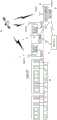
图1是表示本实施方式涉及的、具备基于GNSS信号的行驶位置检测功能的列车的构成的功能框图。FIG. 1 is a functional block diagram showing the configuration of a train having a running position detection function based on GNSS signals according to the present embodiment.
图2是对本实施方式涉及的、执行基于GNSS信号的行驶位置检测功能时的检定处理原理进行说明的图。FIG. 2 is a diagram illustrating the principle of verification processing when the function of detecting the traveling position based on the GNSS signal is executed according to the present embodiment.
图3是对本实施方式涉及的、基于GNSS信号的行驶位置检测功能进行说明的图。FIG. 3 is a diagram illustrating a traveling position detection function based on a GNSS signal according to the present embodiment.
图4是对本实施方式涉及的、基于GNSS信号的行驶位置检测功能进行说明的图。FIG. 4 is a diagram illustrating a traveling position detection function based on a GNSS signal according to the present embodiment.
图5是表示本实施方式涉及的、搭载于前头的车辆的车上装置的构成的功能框图。FIG. 5 is a functional block diagram showing the configuration of an on-vehicle device mounted on a leading vehicle according to the present embodiment.
图6是对本实施方式涉及的、GNSS误差修正的概念进行说明的图。FIG. 6 is a diagram illustrating the concept of GNSS error correction according to the present embodiment.
图7是本实施方式涉及的、基于GNSS信号的位置计算处理的流程图。FIG. 7 is a flowchart of position calculation processing based on GNSS signals according to the present embodiment.
具体实施方式Detailed ways
下面,参照附图对用于实施本发明的方式(以下简称为“实施方式”)具体地进行说明。Hereinafter, modes for implementing the present invention (hereinafter simply referred to as "embodiments") will be specifically described with reference to the drawings.
图1是表示本实施方式涉及的、列车运行系统1的概要的图。图2是列车运行系统1的框图。在图1中,示出向图示右方向进入的车辆10的前头进入了月台88的状态。FIG. 1 is a diagram showing an overview of a train operating system 1 according to the present embodiment. FIG. 2 is a block diagram of the train operating system 1 . In FIG. 1 , a state in which the front end of the
如图1所示,列车运行系统1中,作为车辆侧的装置而在前头的车辆10中具备第1GNSS部15、第2GNSS部16及车上装置20,作为地上侧的装置而在车站的月台88具备地上装置60及第3GNSS部61。进而,列车运行系统1中,作为地上侧的装置还具备对车辆10和车上装置20进行控制,总体地进行运行管理的指令中心70。As shown in Fig. 1, in the train operation system 1, as the device on the vehicle side, the
在本实施方式中,使用车辆侧的第1GNSS部15、第2GNSS部16和地上侧的第3GNSS部61,提高车站(月台88)附近地域的车辆位置的计算精度。In this embodiment, the calculation accuracy of the vehicle position in the vicinity of the station (platform 88 ) is improved by using the
若列车进入了规定的通信区域,则地上装置60将第3GNSS部61所获得的GNSS信息向车上装置20发送。已经知道第3GNSS部61的第3GNSS接收部61a的绝对位置,例如将所获得的GNSS信息与绝对值之差(以下称为“GNSS误差”。)向车上装置20通知。在存在于月台88附近的车辆10(第1GNSS部15、第2GNSS部16)中,基于来自与第3GNSS部61相同的GNSS卫星98的GNSS信息计算位置信息。When the train enters a predetermined communication area, the
另外,也可以,车辆10的车上装置20将基于第1GNSS部15及第2GNSS部16的位置信息向地上侧的指令中心70发送,地上装置60将第3GNSS部61的GNSS误差信息向地上侧的指令中心70发送。在该情况下,指令中心70能够准确地进行车辆10的位置修正,能够基于该列车位置(车辆10的修正后的位置)进行联动控制或信号控制。Alternatively, the on-
计算出的位置信息包含由第3GNSS部61计算出的GNSS误差的可能性较高。因此,在车上装置20中,当基于第1GNSS部15及第2GNSS部16的GNSS信息计算位置信息的情况下,获得由第3GNSS部61计算出的GNSS误差作为GNSS误差信息,并将其反映,进行将GNSS误差排除的处理。此外,如上述那样,也可以,在指令中心70从车辆10或地上装置60获得位置信息的情况下,指令中心70进行将GNSS误差排除的处理。在下面,主要对由车辆10和地上装置60进行GNSS误差的排除处理的实例进行说明。It is highly likely that the calculated position information includes the GNSS error calculated by the
对于车辆10侧的构成,第1GNSS部15具备第1GNSS天线15a及第1GNSS接收部15b。第2GNSS部16具备第2GNSS天线16a和第2GNSS接收部16b。Regarding the configuration on the
第1GNSS天线15a设置于车辆10的上部前端附近。第2GNSS天线16a设置于车辆10的上部后端附近。第1GNSS天线15a和第2GNSS天线16a隔开规定的距离(以下称为“设置距离a”)而设置。例如,在车辆10的长度为20m的情况下,设置距离a为17m左右。The
第1GNSS接收部15b基于第1GNSS天线15a接收到的GNSS信号计算第1GNSS天线15a的位置信息,并且,计算第1GNSS天线15a的位置处的速度向量,将各计算结果向车上装置20输出。The first
第2GNSS接收部16b基于第2GNSS天线16a接收到的GNSS信号计算第2GNSS天线16a的位置信息,并且,计算第2GNSS天线16a的位置处的速度向量,将各计算结果向车上装置20输出。The second
车上装置20在检测出速度向量的特征点时,与预先准备的系统固有的信息进行比较,来确定车辆10的位置。另外,车上装置20在从地上装置60获得了第3GNSS部61的位置信息的情况下,将该位置信息反映到第1GNSS部15及第2GNSS部16的计算结果中,对位置信息进行修正。When the on-
在此,参照图3~图5,对基于GNSS信号的行驶位置检测的原理及位置信息的修正处理进行说明。在本实施方式中,如上述那样,车上装置20在检测出速度向量变化的规定的特征点时,与预先准备的系统固有的信息(运行用数据部31的信息)进行比较,在判断为与预想的特征点一致的情况下,判断为“处于在数据库中记录的位置”。在此,所谓特征点,例如,是轨道99转弯时的其起点或终点等。此外,在特征点的检测处理之前,执行是否是处于也可以执行基于GNSS信号的位置信息的计算处理的状态的GNSS检定。另外,在车站(月台88)等那样的需要精度较高的位置信息的区域,基于地上侧的位置信息及该地点的GNSS信息,修正GNSS误差。Here, the principle of the traveling position detection based on the GNSS signal and the correction process of the position information will be described with reference to FIGS. 3 to 5 . In the present embodiment, as described above, when the on-
<基本技术><Basic Technology>
1.GNSS检定1. GNSS verification
GNSS检定是为了提高GNSS信息的可靠性而进行的。只在GNSS检定合格时,将基于该GNSS信息的位置信息使用于车辆10的位置确定中。在GNSS检定中,使用车辆10的2台的GNSS接收机(第1GNSS接收部15b、第2GNSS接收部16b)。GNSS verification is performed to improve the reliability of GNSS information. Only when the GNSS certification is passed, the position information based on the GNSS information is used to determine the position of the
如上述那样,第1GNSS天线15a和第2GNSS天线16a以无相关性的设置距离a而设置。具体地,在车辆10的前后端(例如前头的车辆10的前头侧和连结侧的两个地方)设置有第1GNSS天线15a和第2GNSS天线16a。这时,不只是设置距离a,也构建了基于车辆10的顶棚的、电波环境的非相关环境。即,对第1及第2GNSS天线15a、16a,构建了不同的衰落环境。由此,两个GNSS接收机(第1及第2GNSS接收部15b、16b)构成为,不会由于相同的衰落的影响而输出错误信息。As mentioned above, the
在GNSS检定的逻辑中,将来自GNSS卫星98的信息与系统固有的信息进行比较,只在检定合格时使用GNSS信息。In the logic of the GNSS verification, the information from the
2.使用了GNSS信息的速度信息的基于行驶距离累计进行的位置检测2. Position detection based on cumulative travel distance using speed information from GNSS information
通过在确定了绝对位置后,对速度信息进行积分计算行驶距离,来进行基于GNSS信息的速度信息的累计的位置检测。Position detection based on accumulation of speed information of GNSS information is performed by integrating the speed information to calculate the traveling distance after the absolute position is determined.
在GNSS检定逻辑中,使用了图3中(a)的“轨迹”检定、图3中(b)的“位置”检定、图3中(c)的“方位(Dp)”检定。只在检定合格的情况下,利用基于GNSS信息的速度信息。在检定不合格的情况下,利用来自TG32(参照图5)等其他速度检测单元的速度信息。此外,在检定时,参照运行用数据部31,与所记录的数据进行比较。In the GNSS verification logic, the "trajectory" verification of (a) in Figure 3, the "position" verification of (b) in Figure 3, and the "orientation (Dp)" verification of (c) in Figure 3 are used. Use speed information based on GNSS information only if certified. When the test fails, speed information from other speed detection means such as TG32 (see FIG. 5 ) is used. In addition, at the time of testing, the
所谓“轨迹”检定,是判断是否在预定的行驶路径行驶。所谓“位置”检定,是判断根据GNSS信号得到的第1及第2GNSS天线15a、16a的间隔(后述的图4的“实测距离D”)是否与实际的设置距离a一致。所谓“方位”检定,是判断是否与预定的方位(轨道方位)一致。The so-called "trajectory" test is to judge whether the vehicle is traveling on a predetermined driving route. The so-called "position" verification is to judge whether the distance between the first and
3.使用了GNSS的速度信息的绝对位置检测3. Absolute position detection using GNSS speed information
在使用了GNSS的速度信息的绝对位置检测中,利用了由2台GNSS接收机(第1GNSS接收部15b、第2GNSS接收部16b)计算的速度向量在轨道99的弯道处时时刻刻变化这一情况。对于该轨道的弯道处的速度向量的变化,如果满足以下所示的条件(a)~(c),则成为由GNSS的故障、接收机的故障、衰落的影响而产生的变化和识别不能的概率极低。In absolute position detection using GNSS speed information, the fact that the speed vector calculated by two GNSS receivers (the
(a)在弯道起点前通过TG等预计了弯道的起点到来这一情况。(a) The arrival of the start of the curve is predicted by the TG or the like before the start of the curve.
(b)从弯道起点前到弯道终点后GNSS检定合格。(b) Pass the GNSS verification from before the start of the curve to after the end of the curve.
(c)在路线数据库(运行用数据部31)中登记有绝对位置检测信息。(c) Absolute position detection information is registered in the route database (operation data part 31).
(1)基于轨道的曲率进行的位置检测(1) Position detection based on the curvature of the track
参照图4对基于轨道99的曲率的位置检测处理进行说明。在此,代替曲率而使用了曲率半径R。对于从2台GNSS接收机(第1GNSS接收部15b、第2GNSS接收部16b)得到的速度向量V(V1、V2),若车辆10从直线99a进入了弯道99b,则与轨道99(弯道99b)的曲率半径R相应地,角度θ发生变化。在此,将第1GNSS天线15a的速度向量V1和第2GNSS天线16a的速度向量V2所成的角设为角度θ。The position detection processing based on the curvature of the
根据该角度θ利用下面的式计算轨道99(弯道99b)的曲率半径R,并与路线数据库(运行用数据部31)中登记的轨道99的曲率(曲率半径)进行比较,从而来确定弯道位置(起点C1和终点C2),在终点C2成为θ=0度的地点,设为检测出绝对位置。Calculate the radius of curvature R of the track 99 (
Sin(θ/2)=(D/2)/RSin(θ/2)=(D/2)/R
R=(D/2)/Sin(θ/2)R=(D/2)/Sin(θ/2)
D:基于GNSS信号计算的第1GNSS天线15a和第2GNSS天线16a之间的实测距离。D: The measured distance between the
(2)基于轨道的弯道行驶距离进行的位置检测(2) Position detection based on the curve travel distance of the track
在上述的基于轨道99的曲率(曲率半径R)进行的位置检测的情况下,若曲率较大,则角度θ的绝对值变小,因此,由于误差,有时不能确定弯道位置。因此,在曲率比规定大的情况下,进行基于轨道99的弯道行驶距离LR的位置检测。即,计算从轨道99成为弯道99b的起点C1到终点C2的弯道行驶距离LR,并与路线数据库(运行用数据部31)中登记的弯道99b的距离进行比较,从而,来确定弯道位置,在弯道终点成为θ=0度的地点,设为检测出绝对位置。In the above-mentioned position detection based on the curvature (curvature radius R) of the
(3)基于轨道的弯道变化点进行的位置检测(3) Position detection based on the curve change point of the track
如图5所示那样,对于从第1GNSS天线15a、第2GNSS天线16a得到的速度向量差,在轨道99从右弯道99d向左弯道99e、从左弯道向右弯道变化的情况下,若取速度向量V1和V2之差,则符号(正负)反转。根据在该轨道的弯道变化点C3的前后GNSS检定合格,满足上述的条件(a)和(b),从而确定弯道变化点C3,在弯道变化点C3处设为检测出绝对位置。As shown in FIG. 5, regarding the speed vector difference obtained from the
(4)向系统的适用(4) Application to the system
此外,对于上述的(1)~(3)的位置检测的方式,配合适用路线区间进行选择组合。In addition, for the above-mentioned position detection methods (1) to (3), select and combine them according to the applicable route section.
4.使用了地上侧的GNSS信息的位置修正4. Position correction using GNSS information on the ground side
在车站(月台88)等那样的需要精度较高的位置信息的区域,基于地上侧的位置信息及该地点的GNSS信息,修正GNSS误差。图6是对GNSS误差修正的概念进行说明的图。In areas where highly accurate positional information is required, such as a station (platform 88 ), GNSS errors are corrected based on the positional information on the ground side and the GNSS information at that point. FIG. 6 is a diagram illustrating the concept of GNSS error correction.
在第3GNSS接收部61a中,记录有第3GNSS天线61b的测量完成的固定位置信息P3(X3_0、Y3_0)。位置信息P3是固定值,例如由经度、纬度表示。第3GNSS接收部61a计算基于GNSS卫星98得到的位置信息P3_G(X3_g、Y3_g)和固定位置信息P3(X3_0、Y3_0)之差即GNSS误差信息ΔP3(Δx、Δy)。In the 3rd
ΔP3(Δx、Δy)=(X3_g、Y3_g)-(X3_0、Y3_0)ΔP3(Δx, Δy)=(X3_g, Y3_g)-(X3_0, Y3_0)
=(X3_g-X3_0、Y3_g-Y3_0)=(X3_g-X3_0, Y3_g-Y3_0)
第3GNSS接收部61a将该GNSS误差ΔP3(Δx、Δy)作为GNSS误差信息向车上装置20发送。The third
车上装置20中,在第1GNSS部15及第2GNSS部16的GNSS信息P1_G(X1_g、Y1_g)、P2_G(X2_g、Y2_g)中反映GNSS误差ΔP3(Δx、Δy),计算修正后GNSS信息P1_0(X1_0、Y1_0)、P2_G(X2_0、Y2_0)。In the on-
P1_0(X1_0、Y1_0)=(X1_g-Δx、Y1_g-Δy)P1_0(X1_0, Y1_0)=(X1_g-Δx, Y1_g-Δy)
P2_0(X2_0、Y2_0)=(X2_g-Δx、Y2_g-Δy)P2_0(X2_0, Y2_0)=(X2_g-Δx, Y2_g-Δy)
在此,通过将适用GNSS误差信息时的车辆10(车上装置20)与地上装置60之间的距离设为使用相同的GNSS卫星98的充分近的范围内,从而能够实质上消除第1GNSS部15及第2GNSS部16中的测量误差,能够提高使用第1GNSS部15及第2GNSS部16计算的车辆10的列车位置的精度。Here, by setting the distance between the vehicle 10 (on-vehicle device 20 ) and the
<具体的技术><specific technique>
参照图2对用于执行上述的绝对位置检测处理及GNSS误差修正处理的构成进行说明。A configuration for executing the above-mentioned absolute position detection processing and GNSS error correction processing will be described with reference to FIG. 2 .
地上装置60具备:地上侧运行控制部62、和地上通信部63。地上侧运行控制部62保持第3GNSS天线61b的设置位置的位置信息,并且,获得第3GNSS部61接收到的GNSS信号,计算设置位置的位置信息与根据GNSS信号计算的位置信息之差(GNSS误差信息),并通过地上通信部63向车上装置20发送。地上通信部63与车上装置20(车上通信部33)进行通信。The
车上装置20设置于设置有第1GNSS部15及第2GNSS部16的车辆10中,对列车(车辆10)的运行进行控制。具体地,车上装置20对列车速度进行控制、对列车位置进行推断、或对列车朝向进行推断,从而来把握列车(车辆10)的运行状态,执行适当的列车运行。另外,车上装置20与地上装置60进行通信,直接或间接地进行线路封闭等的处理。The on-
车上装置20具备:车上侧运行控制部30、列车状态确定部40、运行用数据部31、TG32、车上通信部33、和行驶履历部34。The on-
运行用数据部31记录有列车(车辆10)运行的路线的信息(运行信息)。作为运行信息,有列车(车辆10)行驶的路径信息、地点信息、各地点处的列车行进方向的方位Dp、弯道信息(起点、终点、曲率半径)及每个速度限制区间的限制速度信息等。The
行驶履历部34记录车辆10的行驶履历。TG32是以往使用的基于车轮旋转测量速度的速度测量装置。车上通信部33通过无线与地上装置60的地上通信部63及其他外部装置(例如运行司令部等)收发信息。The
车上侧运行控制部30使用列车状态确定部40或TG32、运行用数据部31进行列车运行控制。所谓列车运行控制,例如,对列车(车辆10)的位置进行确定,或对速度进行计算,将计算结果等显示在规定的显示装置。对于速度显示,可以显示其中任意一者的速度,也可以显示两者的速度。The on-board
列车状态确定部40具备:列车位置计算部42、列车方位计算部44、GNSS检定部46、和特定位置检测部48。The train
列车位置计算部42从第1GNSS部15及第2GNSS部16获得各自检测出的位置信息。另外,列车位置计算部42基于从第1及第2GNSS部15、16输出的位置信息,计算第1GNSS天线15a、第2GNSS天线16a之间的实测距离D。The train
列车方位计算部44基于列车位置计算部42所获得的位置信息,计算车辆10的行进方向(方位)。将所计算的行进方向(方位)向特定位置检测部48输出。The train
GNSS检定部46进行上述的GNSS检定处理。即,GNSS检定部46进行图3中(a)的“轨迹”检定、图3中(b)的“位置”检定、图3中(c)的“方位”检定中所示的处理。这时,GNSS检定部46参照运行用数据部31。The
在判断为GNSS检定合格的情况下,特定位置检测部48进行上述的使用了GNSS的速度信息的绝对位置检测处理。若进行了绝对位置检测处理,则用于车上侧运行控制部30等进行的列车(车辆10)的各种控制的位置信息被更新为检测到的位置信息。即,例如,即使在由于在执行绝对位置检测处理之前的行驶状态的把握中使用TG32,从而由于车轮的空转或滑行等而产生误差的情况下,也能够适当地消除该误差。此外,车上侧运行控制部30也可以在所产生的误差为规定以上而较大的情况下,判断为有可能列车(车辆10)的车轮等发生故障或存在运行用数据部31的数据的错误等,并向驾驶员发出警报,或通过车上通信部33向运行司令部等通知。When it is determined that the GNSS test is passed, the specific
对于绝对位置检测处理,特定位置检测部48选择性地使用(1)基于轨道的曲率进行的位置检测、(2)基于轨道的弯道行驶距离进行的位置检测、(3)基于轨道的弯道变化点进行的位置检测这3种位置检测方法。也可以根据需要将这些组合。For the absolute position detection process, the specific
另外,特定位置检测部48在车辆10距地上装置60位于规定距离内的情况下,从地上装置60获得GNSS误差信息,并反映到第1GNSS部15及第2GNSS部16检测到的位置信息中。Furthermore, when the
参照图7的流程图,对基于以上的构成的处理进行归纳说明。Processing based on the above configuration will be collectively described with reference to the flowchart of FIG. 7 .
在车上装置20中,列车状态确定部40的列车位置计算部42基于第1GNSS部15及第2GNSS部16接收到的GNSS信号,计算位置信息(S10)。接着,GNSS检定部46进行GNSS检定,判断是否处于能够使用GNSS信息的状况(S12)。In the on-
在GNSS检定不合格的情况下(S14的“否”),车上侧运行控制部30进行使用了TG32的列车位置计算处理,进行基于其的运行控制(S16)。在GNSS检定合格的情况下(S14的“是”),车上侧运行控制部30判断是否是处于与地上装置60有通信且使用地上装置60(第3GNSS部61)的GNSS信息的区域(S18)。在不是使用地上装置60(第3GNSS部61)的GNSS信息的区域的情况下(S18的“否”),即,在是不使用GNSS误差信息的区域的情况下,车上装置20进行使用了车上GNSS数据(第1GNSS部15、第2GNSS部16的GNSS信息)的列车位置计算,进行基于其的运行控制(S20)。When the GNSS test fails (No in S14), the on-vehicle
在是使用地上装置60(第3GNSS部61)的GNSS信息的区域内的情况下(S18的“是”),车上装置20从地上装置60获得GNSS误差信息(S22),在车上GNSS数据(第1GNSS部15、第2GNSS部16的GNSS信息)中反映GNSS误差信息(S24),计算修正后的列车位置,进行使用了该列车位置的运行控制(S26)。If it is within the area where the GNSS information of the ground device 60 (third GNSS unit 61) is used ("Yes" in S18), the on-
以上,根据本实施方式,在车辆10中,基于从第1及第2GNSS接收部15b、16b输出的信息能够高精度地稳定地决定列车(车辆10)的绝对位置,该第1及第2GNSS接收部15b、16b与在前后隔开规定的设置距离a而设置的第1及第2GNSS天线15a、16a连接。特别地,在列车进入车站那样的情况下,例如,为了在信号的切换或道口的动作中,迅速且安全地进行这些,要求精度较高的列车位置检测。更具体地,需要在适当的时刻进行轨道的禁止通行区间的设定、解除。在这样的情况下,将月台88的地上装置60的第3GNSS部61的GNSS误差信息反映到通过车辆10的第1GNSS部15、第2GNSS部16得到的位置信息中,能够排除位置信息的误差,能够迅速、安全地进行使用了该位置信息的运行控制。As described above, according to the present embodiment, in the
以上,基于实施方式对本发明进行了说明。该实施方式是示例,本领域技术人员能够理解,通过这些各构成要素的组合能够实现各种各样的变形例,另外,这样的变形例也属于本发明的范围内。As mentioned above, this invention was demonstrated based on embodiment. This embodiment is an example, and it will be understood by those skilled in the art that various modifications can be realized by combinations of these constituent elements, and such modifications also fall within the scope of the present invention.
附图标记说明Explanation of reference signs
1列车运行系统(位置检测系统)1 Train operation system (position detection system)
10车辆10 vehicles
15第1GNSS部15 Part 1 GNSS
15a第1GNSS天线15a 1st GNSS Antenna
15b第1GNSS接收部15b 1st GNSS receiving unit
16第2GNSS部16 Part 2 GNSS
16a第2GNSS天线16a 2nd GNSS Antenna
16b第2GNSS接收部16b 2nd GNSS receiving unit
20车上装置(位置检测装置)20 On-vehicle device (position detection device)
30 车上侧运行控制部30 On-vehicle running control unit
31 运行用数据部31 Data section for operation
32TG32TG
33 车上通信部33 In-vehicle communication department
34 行驶履历部34 Driving History Department
40 列车状态确定部40 Train Status Confirmation Department
42 列车位置计算部42 Train position calculation unit
44 列车方位计算部44 Train direction calculation department
46GNSS检定部46GNSS Testing Department
48 特定位置检测部48 Specific position detection unit
60 地上装置60 above-ground installations
61第3GNSS部61 Part 3 GNSS
61a第3GNSS接收部61a 3rd GNSS receiving unit
61b第3GNSS天线61b 3rd GNSS Antenna
62 地上侧运行控制部62 Ground side operation control department
63 地上通信部63 Ground Communications Department
70 指令中心70 Command Center
88 月台
99 轨道99 tracks
Claims (2)
Translated fromChineseApplications Claiming Priority (3)
| Application Number | Priority Date | Filing Date | Title |
|---|---|---|---|
| JP2017108891AJP6534701B2 (en) | 2017-06-01 | 2017-06-01 | Position detection system |
| JP2017-108891 | 2017-06-01 | ||
| PCT/JP2018/020630WO2018221541A1 (en) | 2017-06-01 | 2018-05-30 | Position detection device and position detection system |
Publications (2)
| Publication Number | Publication Date |
|---|---|
| CN110914710A CN110914710A (en) | 2020-03-24 |
| CN110914710Btrue CN110914710B (en) | 2023-06-27 |
Family
ID=64455795
Family Applications (1)
| Application Number | Title | Priority Date | Filing Date |
|---|---|---|---|
| CN201880035663.3AActiveCN110914710B (en) | 2017-06-01 | 2018-05-30 | Position detection system |
Country Status (4)
| Country | Link |
|---|---|
| JP (1) | JP6534701B2 (en) |
| CN (1) | CN110914710B (en) |
| TW (1) | TWI775864B (en) |
| WO (1) | WO2018221541A1 (en) |
Families Citing this family (2)
| Publication number | Priority date | Publication date | Assignee | Title |
|---|---|---|---|---|
| CN112578420B (en)* | 2020-12-22 | 2022-08-30 | 卡斯柯信号有限公司 | Locomotive running state detection method based on satellite positioning |
| TWI760261B (en)* | 2021-07-14 | 2022-04-01 | 交通部臺灣鐵路管理局 | Train speed monitoring system |
Citations (6)
| Publication number | Priority date | Publication date | Assignee | Title |
|---|---|---|---|---|
| JP2003294825A (en)* | 2002-03-28 | 2003-10-15 | Railway Technical Res Inst | Train own vehicle position detecting method and train own vehicle position detecting system |
| JP2005247042A (en)* | 2004-03-02 | 2005-09-15 | Mitsubishi Electric Corp | An operation server for train position detection management, an in-vehicle device for train position detection management, a train position detection management method, a train position detection management system, and a train position display device. |
| CN103625507A (en)* | 2012-08-24 | 2014-03-12 | 河南蓝信科技有限公司 | Train tracking approaching early warning method for high speed railway and system thereof |
| CN104220880A (en)* | 2012-03-30 | 2014-12-17 | 日本信号株式会社 | Speed detection device |
| JP5973024B1 (en)* | 2015-04-02 | 2016-08-17 | 株式会社京三製作所 | Position detection device |
| CN106662447A (en)* | 2014-05-07 | 2017-05-10 | 大陆-特韦斯股份有限公司 | Determination of redundant absolute positions using a dynamic driving sensor |
Family Cites Families (7)
| Publication number | Priority date | Publication date | Assignee | Title |
|---|---|---|---|---|
| JP3753833B2 (en)* | 1997-03-27 | 2006-03-08 | アジア航測株式会社 | Road linear automatic surveying equipment |
| JP2007284013A (en)* | 2006-04-20 | 2007-11-01 | Mitsubishi Electric Corp | VEHICLE POSITIONING DEVICE AND VEHICLE POSITIONING METHOD |
| CN101357644B (en)* | 2008-09-08 | 2010-12-15 | 北京交通大学 | Locomotive wheel diameter automatic calibration system and method based on satellite positioning |
| JP4926213B2 (en)* | 2009-07-15 | 2012-05-09 | 株式会社京三製作所 | Train control device |
| US10267892B2 (en)* | 2010-10-04 | 2019-04-23 | Qualcomm Incorporated | Locating a device using a reference point to align location information |
| DE102013205486A1 (en)* | 2013-03-27 | 2014-10-02 | Deere & Company | Arrangement and method for position detection with a hand-held device |
| JP6279425B2 (en)* | 2014-08-05 | 2018-02-14 | 公益財団法人鉄道総合技術研究所 | Program and data generation device |
- 2017
- 2017-06-01JPJP2017108891Apatent/JP6534701B2/enactiveActive
- 2018
- 2018-05-30WOPCT/JP2018/020630patent/WO2018221541A1/ennot_activeCeased
- 2018-05-30CNCN201880035663.3Apatent/CN110914710B/enactiveActive
- 2018-06-01TWTW107118930Apatent/TWI775864B/enactive
Patent Citations (6)
| Publication number | Priority date | Publication date | Assignee | Title |
|---|---|---|---|---|
| JP2003294825A (en)* | 2002-03-28 | 2003-10-15 | Railway Technical Res Inst | Train own vehicle position detecting method and train own vehicle position detecting system |
| JP2005247042A (en)* | 2004-03-02 | 2005-09-15 | Mitsubishi Electric Corp | An operation server for train position detection management, an in-vehicle device for train position detection management, a train position detection management method, a train position detection management system, and a train position display device. |
| CN104220880A (en)* | 2012-03-30 | 2014-12-17 | 日本信号株式会社 | Speed detection device |
| CN103625507A (en)* | 2012-08-24 | 2014-03-12 | 河南蓝信科技有限公司 | Train tracking approaching early warning method for high speed railway and system thereof |
| CN106662447A (en)* | 2014-05-07 | 2017-05-10 | 大陆-特韦斯股份有限公司 | Determination of redundant absolute positions using a dynamic driving sensor |
| JP5973024B1 (en)* | 2015-04-02 | 2016-08-17 | 株式会社京三製作所 | Position detection device |
Also Published As
| Publication number | Publication date |
|---|---|
| TW201903433A (en) | 2019-01-16 |
| CN110914710A (en) | 2020-03-24 |
| TWI775864B (en) | 2022-09-01 |
| JP6534701B2 (en) | 2019-06-26 |
| JP2018205048A (en) | 2018-12-27 |
| WO2018221541A1 (en) | 2018-12-06 |
Similar Documents
| Publication | Publication Date | Title |
|---|---|---|
| JP5973024B1 (en) | Position detection device | |
| JP5249556B2 (en) | On-board device for travel route detection | |
| JP5422111B2 (en) | On-board device for travel route detection | |
| EP2019287B1 (en) | Vehicle positioning information update device | |
| US10928205B2 (en) | In-vehicle device and vehicle | |
| US20180328744A1 (en) | Travelling road information generation system of vehicle and on-board apparatus based on correction amount | |
| WO2015115405A1 (en) | Position measurement method, own position measurement device, and in-vehicle device | |
| JP2008196906A (en) | Vehicle position detection system, in-vehicle device, and vehicle position detection method | |
| JP2008014713A (en) | Position information utilizing system | |
| US11383725B2 (en) | Detecting vehicle environment sensor errors | |
| JP4945286B2 (en) | Train position detector | |
| JP2007284013A (en) | VEHICLE POSITIONING DEVICE AND VEHICLE POSITIONING METHOD | |
| WO2014132432A1 (en) | Device for controlling display of vehicle location and program for identifying vehicle location | |
| CN108931260A (en) | Automatic driving vehicle positioning security test macro and method when GPS is cheated | |
| CN110914710B (en) | Position detection system | |
| JP2010019588A (en) | Vehicle navigation system and correction method of position information in vehicle navigation system, and information distribution server and in-vehicle navigation apparatus | |
| JP2010210435A (en) | Method of detecting reverse running in navigation apparatus | |
| JPH04138317A (en) | Navigation device using vehicle-to-vehicle communication | |
| JP6511767B2 (en) | Reverse run judging device | |
| JP2011125128A (en) | Train control unit | |
| JP6173714B2 (en) | In-vehicle device, position correction method thereof, and position correction program | |
| JP5446603B2 (en) | In-vehicle device and program | |
| KR100518850B1 (en) | Global Positioning System and the method of navigate information correcting in time | |
| JP5015021B2 (en) | Own vehicle position detection device | |
| JP7497286B2 (en) | Surrounding vehicle monitoring system |
Legal Events
| Date | Code | Title | Description |
|---|---|---|---|
| PB01 | Publication | ||
| PB01 | Publication | ||
| SE01 | Entry into force of request for substantive examination | ||
| SE01 | Entry into force of request for substantive examination | ||
| GR01 | Patent grant | ||
| GR01 | Patent grant |