CN110914023B - Power supply device - Google Patents
Power supply deviceDownload PDFInfo
- Publication number
- CN110914023B CN110914023BCN201880032034.5ACN201880032034ACN110914023BCN 110914023 BCN110914023 BCN 110914023BCN 201880032034 ACN201880032034 ACN 201880032034ACN 110914023 BCN110914023 BCN 110914023B
- Authority
- CN
- China
- Prior art keywords
- unit
- arm
- power supply
- power
- power receiving
- Prior art date
- Legal status (The legal status is an assumption and is not a legal conclusion. Google has not performed a legal analysis and makes no representation as to the accuracy of the status listed.)
- Active
Links
- 238000001514detection methodMethods0.000description12
- 230000008859changeEffects0.000description4
- 230000007246mechanismEffects0.000description3
- 238000010586diagramMethods0.000description2
- 238000000034methodMethods0.000description2
- 239000006096absorbing agentSubstances0.000description1
- 238000013459approachMethods0.000description1
- 230000000694effectsEffects0.000description1
- 238000003384imaging methodMethods0.000description1
- 238000009434installationMethods0.000description1
- 238000001179sorption measurementMethods0.000description1
Images


Classifications
- B—PERFORMING OPERATIONS; TRANSPORTING
- B25—HAND TOOLS; PORTABLE POWER-DRIVEN TOOLS; MANIPULATORS
- B25J—MANIPULATORS; CHAMBERS PROVIDED WITH MANIPULATION DEVICES
- B25J13/00—Controls for manipulators
- B25J13/08—Controls for manipulators by means of sensing devices, e.g. viewing or touching devices
- B—PERFORMING OPERATIONS; TRANSPORTING
- B25—HAND TOOLS; PORTABLE POWER-DRIVEN TOOLS; MANIPULATORS
- B25J—MANIPULATORS; CHAMBERS PROVIDED WITH MANIPULATION DEVICES
- B25J11/00—Manipulators not otherwise provided for
- B25J11/008—Manipulators for service tasks
- B—PERFORMING OPERATIONS; TRANSPORTING
- B25—HAND TOOLS; PORTABLE POWER-DRIVEN TOOLS; MANIPULATORS
- B25J—MANIPULATORS; CHAMBERS PROVIDED WITH MANIPULATION DEVICES
- B25J17/00—Joints
- B25J17/02—Wrist joints
- B25J17/0208—Compliance devices
- B—PERFORMING OPERATIONS; TRANSPORTING
- B25—HAND TOOLS; PORTABLE POWER-DRIVEN TOOLS; MANIPULATORS
- B25J—MANIPULATORS; CHAMBERS PROVIDED WITH MANIPULATION DEVICES
- B25J19/00—Accessories fitted to manipulators, e.g. for monitoring, for viewing; Safety devices combined with or specially adapted for use in connection with manipulators
- B25J19/02—Sensing devices
- B25J19/021—Optical sensing devices
- B25J19/023—Optical sensing devices including video camera means
- B—PERFORMING OPERATIONS; TRANSPORTING
- B60—VEHICLES IN GENERAL
- B60L—PROPULSION OF ELECTRICALLY-PROPELLED VEHICLES; SUPPLYING ELECTRIC POWER FOR AUXILIARY EQUIPMENT OF ELECTRICALLY-PROPELLED VEHICLES; ELECTRODYNAMIC BRAKE SYSTEMS FOR VEHICLES IN GENERAL; MAGNETIC SUSPENSION OR LEVITATION FOR VEHICLES; MONITORING OPERATING VARIABLES OF ELECTRICALLY-PROPELLED VEHICLES; ELECTRIC SAFETY DEVICES FOR ELECTRICALLY-PROPELLED VEHICLES
- B60L53/00—Methods of charging batteries, specially adapted for electric vehicles; Charging stations or on-board charging equipment therefor; Exchange of energy storage elements in electric vehicles
- B60L53/30—Constructional details of charging stations
- B60L53/35—Means for automatic or assisted adjustment of the relative position of charging devices and vehicles
- B60L53/37—Means for automatic or assisted adjustment of the relative position of charging devices and vehicles using optical position determination, e.g. using cameras
- H—ELECTRICITY
- H02—GENERATION; CONVERSION OR DISTRIBUTION OF ELECTRIC POWER
- H02J—CIRCUIT ARRANGEMENTS OR SYSTEMS FOR SUPPLYING OR DISTRIBUTING ELECTRIC POWER; SYSTEMS FOR STORING ELECTRIC ENERGY
- H02J7/00—Circuit arrangements for charging or depolarising batteries or for supplying loads from batteries
- Y—GENERAL TAGGING OF NEW TECHNOLOGICAL DEVELOPMENTS; GENERAL TAGGING OF CROSS-SECTIONAL TECHNOLOGIES SPANNING OVER SEVERAL SECTIONS OF THE IPC; TECHNICAL SUBJECTS COVERED BY FORMER USPC CROSS-REFERENCE ART COLLECTIONS [XRACs] AND DIGESTS
- Y02—TECHNOLOGIES OR APPLICATIONS FOR MITIGATION OR ADAPTATION AGAINST CLIMATE CHANGE
- Y02T—CLIMATE CHANGE MITIGATION TECHNOLOGIES RELATED TO TRANSPORTATION
- Y02T10/00—Road transport of goods or passengers
- Y02T10/60—Other road transportation technologies with climate change mitigation effect
- Y02T10/70—Energy storage systems for electromobility, e.g. batteries
- Y—GENERAL TAGGING OF NEW TECHNOLOGICAL DEVELOPMENTS; GENERAL TAGGING OF CROSS-SECTIONAL TECHNOLOGIES SPANNING OVER SEVERAL SECTIONS OF THE IPC; TECHNICAL SUBJECTS COVERED BY FORMER USPC CROSS-REFERENCE ART COLLECTIONS [XRACs] AND DIGESTS
- Y02—TECHNOLOGIES OR APPLICATIONS FOR MITIGATION OR ADAPTATION AGAINST CLIMATE CHANGE
- Y02T—CLIMATE CHANGE MITIGATION TECHNOLOGIES RELATED TO TRANSPORTATION
- Y02T10/00—Road transport of goods or passengers
- Y02T10/60—Other road transportation technologies with climate change mitigation effect
- Y02T10/7072—Electromobility specific charging systems or methods for batteries, ultracapacitors, supercapacitors or double-layer capacitors
- Y—GENERAL TAGGING OF NEW TECHNOLOGICAL DEVELOPMENTS; GENERAL TAGGING OF CROSS-SECTIONAL TECHNOLOGIES SPANNING OVER SEVERAL SECTIONS OF THE IPC; TECHNICAL SUBJECTS COVERED BY FORMER USPC CROSS-REFERENCE ART COLLECTIONS [XRACs] AND DIGESTS
- Y02—TECHNOLOGIES OR APPLICATIONS FOR MITIGATION OR ADAPTATION AGAINST CLIMATE CHANGE
- Y02T—CLIMATE CHANGE MITIGATION TECHNOLOGIES RELATED TO TRANSPORTATION
- Y02T90/00—Enabling technologies or technologies with a potential or indirect contribution to GHG emissions mitigation
- Y02T90/10—Technologies relating to charging of electric vehicles
- Y02T90/12—Electric charging stations
Landscapes
- Engineering & Computer Science (AREA)
- Mechanical Engineering (AREA)
- Robotics (AREA)
- Power Engineering (AREA)
- Transportation (AREA)
- Human Computer Interaction (AREA)
- Multimedia (AREA)
- Charge And Discharge Circuits For Batteries Or The Like (AREA)
- Manipulator (AREA)
- Electric Propulsion And Braking For Vehicles (AREA)
Abstract
Translated fromChinese
Description
Translated fromChinese技术领域technical field
本发明涉及供电装置,特别是涉及向电气设备供给电力的供电装置。The present invention relates to a power supply device, in particular to a power supply device for supplying electric power to electric equipment.
背景技术Background technique
作为现有的供电装置,公知有专利文献1所示的车辆供电设备。在该车辆供电设备中,构成为自走式机器人的供电装置移动至与车辆的受电部对置的位置来向受电部供电。As a conventional power feeding device, a vehicle power feeding device disclosed in Patent Document 1 is known. In this vehicle power feeding facility, the power feeding device configured as a self-propelled robot moves to a position facing the power receiving unit of the vehicle to supply power to the power receiving unit.
专利文献1:日本特开2016-103938号公报Patent Document 1: Japanese Patent Laid-Open No. 2016-103938
在上述专利文献1的车辆供电设备中,在供电装置中使用自走式机器人,因而用于使供电装置移动至车辆的受电部的控制变复杂。In the vehicle power feeding facility of Patent Document 1 described above, a self-propelled robot is used for the power feeding device, and thus the control for moving the power feeding device to the power receiving unit of the vehicle becomes complicated.
发明内容Contents of the invention
本发明是为了解决这样的课题而完成的,其目的在于提供一种能够更简单地使供电部向受电部移动的供电装置。The present invention has been made to solve such problems, and an object of the present invention is to provide a power feeding device that can more easily move a power feeding unit to a power receiving unit.
本发明的某形态所涉及的供电装置具备:供电部,与电气设备的受电部连接并向上述受电部供给电力;臂,上述供电部设置于该臂的前端,且该臂具有直动关节部以及旋转关节部的至少任一方;以及控制部,上述控制部构成为控制上述直动关节部以及上述旋转关节部中的至少任一方来使上述臂移动,以便将上述供电部与上述受电部连接。A power feeding device according to an aspect of the present invention includes: a power feeding unit connected to a power receiving unit of an electric device to supply electric power to the power receiving unit; at least one of a joint part and a rotary joint part; and a control part configured to control at least one of the linear joint part and the rotary joint part to move the arm so that the power supply part and the receiving part are connected to each other. Electrical connection.
在该供电装置中,可以还具备照相机,设置于上述臂,上述控制部构成为基于上述照相机的图像控制上述直动关节部以及上述旋转关节部中的至少任一方来使上述臂移动,以便将上述供电部与上述受电部连接。In this power supply device, a camera may be further provided on the arm, and the control unit may be configured to move the arm by controlling at least one of the linear joint unit and the rotational joint unit based on an image of the camera to move the arm. The power feeding unit is connected to the power receiving unit.
另外,供电装置可以在上述臂的下部还具备能够移动的脚轮。In addition, the power supply device may further include movable casters on the lower portion of the arm.
并且,供电装置可以还具备固定部,该固定部设置于上述臂且将上述臂固定于上述电气设备。Furthermore, the power supply device may further include a fixing portion provided on the arm and fixing the arm to the electric device.
供电装置可以还具备存储部,该存储部对通过移动终端或者手动示教的上述受电部的位置进行存储,上述控制部构成为基于存储于上述存储部的上述受电部的位置使上述臂移动,以便将上述供电部与上述受电部连接。The power supply device may further include a storage unit that stores the position of the power receiving unit taught by a mobile terminal or manually, and the control unit is configured to make the arm move so as to connect the power supply unit to the power reception unit.
供电装置可以还具备误差吸收部,该存储部根据将上述供电部插入至上述受电部时的反作用力使上述供电部位移。The power supply device may further include an error absorbing unit that displaces the power supply unit based on a reaction force when the power supply unit is inserted into the power reception unit.
在供电装置中,可以构成为上述臂具有:基部,固定于地面且沿铅垂方向延伸;第一臂部,通过上述直动关节部与上述基部连结并沿与上述基部交叉的方向延伸;以及第二臂部,通过上述旋转关节部与上述第一臂部连结,且设置于上述第一臂部的直线行进方向,以沿与上述第一臂部交叉的方向延伸的旋转轴为中心旋转。In the power supply device, the arm may include: a base fixed to the ground and extending in a vertical direction; a first arm connected to the base through the linear motion joint and extending in a direction intersecting the base; and The second arm is connected to the first arm via the rotary joint, is provided in a straight travel direction of the first arm, and rotates about a rotation axis extending in a direction intersecting the first arm.
本发明在供电装置中起到能够更简单地使供电部向受电部移动的效果。The present invention has an effect that the power feeding unit can be moved more easily to the power receiving unit in the power feeding device.
参照附图、根据以下的优选的实施形态的详细的说明,本发明的上述目的、其他目的、特征以及优点变清楚。The above object, other objects, features, and advantages of the present invention will become clear from the detailed description of the following preferred embodiments with reference to the accompanying drawings.
附图说明Description of drawings
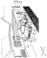
图1是表示本发明的实施方式1所涉及的供电装置的立体图。FIG. 1 is a perspective view showing a power supply device according to Embodiment 1 of the present invention.
图2是表示图1的供电装置的臂的立体图。Fig. 2 is a perspective view showing an arm of the power supply device of Fig. 1 .
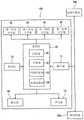
图3是表示图1的供电装置的结构的功能框图。FIG. 3 is a functional block diagram showing the configuration of the power supply device in FIG. 1 .
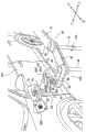
图4是表示图1的照相机拍摄受电部的供电装置的立体图。FIG. 4 is a perspective view showing a power supply device in which the camera of FIG. 1 captures images of a power receiving unit.
图5是表示图4的固定部吸附于车辆的供电装置的立体图。FIG. 5 is a perspective view showing a power supply device in which the fixing portion of FIG. 4 is adsorbed to a vehicle.
图6是表示图5的供电部与受电部连接的供电装置的立体图。FIG. 6 is a perspective view showing the power feeding device in which the power feeding unit and the power receiving unit in FIG. 5 are connected.
图7是表示本发明的实施方式2所涉及的供电装置的结构的功能框图。7 is a functional block diagram showing the configuration of a power supply device according to Embodiment 2 of the present invention.
具体实施方式Detailed ways
以下,参照附图对本发明的实施方式具体地进行说明。此外,在下文中,对在全部的附图中相同或者相当的要素标注相同的参照附图标记,并省略其重复的说明。Hereinafter, embodiments of the present invention will be specifically described with reference to the drawings. In addition, in the following, the same reference numeral is attached|subjected to the same or equivalent element in all drawings, and the overlapping description is abbreviate|omitted.
(实施方式1)(Embodiment 1)
首先,参照图1对本发明的实施方式1所涉及的供电装置100的结构进行说明。例如在设置于房屋之外的停车场等屋外配置有供电装置100以及检测传感器200。供电装置100通过相对于停车在停车场的车辆201的受电部202连接供电装置100的供电部10来进行供电。此外,在说明中,以车辆201为例对供电装置100的供电对象物进行说明,但供电对象物并不局限于此,也可以是在家庭中使用的机器人等电气设备。First, the configuration of a
检测传感器200是检测停车场中的车辆201以及人203的传感器,例如始终对他们的存在进行检测。检测传感器200例如使用照相机,配置为能够对车辆201以及存在于其周围的人203进行拍摄。此外,检测传感器200可以具有图像处理部(未图示),能够基于由照相机拍摄到的图像对车辆201的位置进行检测。另外,图像处理部也可以设置于供电装置100的控制部80。The
接下来,参照图2对供电装置100的结构进行说明。供电装置100由主体20、基部30、以及设置于基部30的多关节臂40构成。例如,在主体20内置有控制该多关节臂40的动作的控制部80。此外,控制部80可以设置于主体20的外部。Next, the configuration of the
基部30固定于停车场的地面,为长方体形状,沿铅垂方向延伸。例如,基部30配置于停车场的后方且右侧。The
臂40构成为从基端侧向前端侧串联排列有多个(在该实施方式中为3个)臂部41、42、43。基部30、最基端侧的臂部(第一臂部41)、以及相邻的臂部41、42、43彼此分别经由关节部连结为相互能够相对位移。在最前端侧的臂部(第三臂部43)设置有供电部10。臂部41、42、43是长条的平板形状,配置为水平或者大致水平。此外,将臂部41、42、43从基端侧起依次称为第一臂部41、第二臂部42以及第三臂部43。The
第一臂部41沿前后方向延伸,通过第一直动关节部44与基部30连结。第一直动关节部44由直动机构构成,该直动机构具有气缸等线性促动器或者伺服马达等驱动源,借助其使第一臂部41相对于基部30向前后方向直线行进。第一臂部41配置于基部30上,与基部30设置于沿前后方向延伸的同轴上。第一臂部41向后方移动、与基部30的重叠越长,臂40的长度在前后方向上越缩短。另一方面,第一臂部41向前方移动、与基部30的重叠越短,臂40的长度在前后方向越延伸。The
第二臂部42的基端重叠在第一臂部41的前端下,通过第一旋转关节部45与第一臂部41连结。第一旋转关节部45由旋转机构构成,该旋转机构具有伺服马达等驱动源,借助其使第二臂部42相对于沿与第一臂部41以及第二臂部42交叉的方向延伸的旋转轴绕第一臂部41相对旋转。由此,第二臂部42以设置在第一臂部41的直线行进方向并沿与第二臂部42交叉的方向延伸的旋转轴为中心旋转。例如,在第一臂部41以及第二臂部42配置为水平的情况下,第一旋转关节部45的旋转轴沿铅垂方向延伸。The base end of the
第三臂部43的基端重叠在第二臂部42的前端上,通过第二旋转关节部46与第二臂部42连结。第二旋转关节部46由旋转机构构成,该旋转机构具有伺服马达等驱动源,借助其使第三臂部43绕沿与第二臂部42以及第三臂部43交叉的方向延伸的旋转轴相对于第二臂部42相对旋转。例如,在第二臂部42以及第三臂部43配置为水平的情况下,第二旋转关节部46的旋转轴沿铅垂方向延伸。The base end of the
另外,第二臂部42被臂支承部47、48在铅垂方向上支承。臂支承部47、48例如为棒状部件,沿铅垂方向延伸,其上端与第二臂部42连接。臂支承部47、48设置有多个(在该实施方式中为2根),一方的臂支承部(第一臂支承部47)配置为与第一旋转关节部45的旋转轴同轴,另一方的臂支承部(第二臂支承部48)配置为与第二旋转关节部46的旋转轴同轴。第一臂支承部47以及第二臂支承部48的长度设定成与第二臂部42连结的第三臂部43的前端的供电部10与车辆201(图1)的受电部202(图1)对置。In addition, the
在第一臂支承部47以及第二臂支承部48各自的下端安装有脚轮47a、48a,脚轮47a、48a配置于停车场上。脚轮47a、48a能够绕与各臂支承部47、48同轴(铅垂方向)的旋转轴旋转,另外,在各臂支承部47、48具有能够绕沿正交方向(水平方向)延伸的旋转轴旋转的车轮。借助该脚轮47a、48a,第一臂支承部47以及第二臂支承部48在水平方向上还能够向前后左右任一方向移动。这样,通过安装了脚轮47a、48a的臂支承部47、48支承臂40,能够使各臂部41、42、43以及各关节部的马达小型化。
供电部10通过设置于第三臂部43的前端的第二直动关节部49安装于第三臂部43。第二直动关节部49具有气缸等线性促动器或者伺服马达等驱动源、支架49a、以及能够相对于支架49a滑动的滑动件49b。The
支架49a通过沿与第三臂部43正交的方向延伸的棒状的支架支承部50安装于第三臂部43上。支架49a为长条的板状体,长边方向延伸为与第三臂部43的延伸方向(长边方向)平行。支架49a在铅垂方向上倾斜成前端比第三臂部43的前端向前方突出、前端比基端靠下方。此外,根据供电部10与受电部202的位置关系,支架49a可以水平,也可以在铅垂方向上倾斜成前端比基端靠上方。The
滑动件49b是板状体,配置于支架49a上,能够在支架49a的前端与基端之间移动。在滑动件49b上安装有供电部10。由此,供电部10被以能够相对于支架49a滑动的方式保持于支架49a上。The
若供电部10向支架49a的基端侧滑动,则供电部10配置于支架49a上。另一方面,若供电部10向支架49a的前端侧滑动,则供电部10比支架49a的前端面向前突出。这样,供电部10能够在通过在支架49a上滑动来保持恒定的角度的姿势的状态下沿第三臂部43的延伸方向平行移动。When the
在供电部10的基端连接有电源线51的一端。电源线51经由臂40以及基部30走线,其另一端与交流电源(未图示)连接。由此,从交流电源向供电部10供给电力。在该供电部10的周围设置有固定部60以及照相机70。One end of a
固定部60是用于将臂40固定于车辆201的部件,例如使用真空吸附体。固定部60具有吸盘61,吸盘61与真空泵、CONVUM(注册商标)等真空产生装置(未图示)经由配管62连接。在配管62例如设置有开闭阀(未图示),通过开闭阀敞开以及关闭配管62,由此进行基于吸盘61的负压的吸附及其解除。The fixing
在固定部60例如设置有多个(在该实施方式中为4个)吸盘61。4个吸盘61在与供电部10的支架49a的倾斜方向正交的方向上以供电部10为中心点对称地配置于供电部10的周围。吸盘61例如经由供电部10的支架49a安装于第三臂部43的前端,配置于比支架49a的前端靠前方。该吸盘61吸附于车辆201,由此完成供电部10的定位。For example, a plurality of (four in this embodiment)
照相机70是用于对与供电部10结合的受电部202(图1)进行拍摄的拍摄部,例如设置于供电部10之上,并安装于第三臂部43的前端。照相机70与图像处理部84(图3)连接,由照相机70拍摄到的图像输出至图像处理部84。The
接下来,参照图3对控制部80进行说明。控制部80具备CPU等运算部81、ROM、RAM等存储部82、以及伺服控制部83,例如是微控制器等具有计算机的机器人控制器。此外,控制部80可以由集中进行控制的单独的控制装置构成,也可以由相互配合分散进行控制的多个控制装置构成。另外,采用了存储部82设置于控制部80内的方式,但并不局限于此,也可以采用存储部82与控制部80独立设置的方式。Next, the
在存储部82存储有作为供电装置100的基本程序、各种固定数据等信息。运算部81通过读出并执行存储于存储部82的基本程序等软件来控制供电装置100的各部的动作。即,运算部81生成臂40的控制指令并将其输出至伺服控制部83。伺服控制部83构成为基于由运算部81生成的控制指令来控制与臂40的关节部对应的伺服马达的驱动。Information such as a basic program of the
控制部80与检测传感器200电连接。控制部80根据从检测传感器200输出的信号来控制各关节部进而使臂40移动。例如,根据来自检测传感器200的检测信号,若在停车场未检测到人203而检测到车辆201,则控制部80控制各关节部使臂40移动以便向与车辆201的受电部202连接的供电部10目标位置输送供电部10。The
该车辆201的供电部10的目标位置可以预先存储于存储部82。控制部80可以使用通过移动终端204或者手动示教的供电部10的目标位置。在该情况下,控制部80与装备于供电装置100的输入部71连接,将从输入部71输入的供电部10的目标位置存储于存储部82。The target position of the
例如可以是用户使供电部10移动至与受电部202连接的位置地操作输入部71,由此控制部80将该位置作为供电部10的目标位置存储(注册)于存储部82。或者,也可以是用户通过移动终端204发送受电部202的位置,输入部71接收该信息,由此控制部80将该位置作为供电部10的目标位置注册于存储部82。For example, the user operates
另外,在控制部80设置有图像处理部84。图像处理部84基于预先存储于存储部82的检测对象亦即车辆201的受电部202的特征从自照相机70输出的图像检测受电部202,确定受电部202的位置。此外,采用了图像处理部84设置于控制部80内的方式,但并不局限于此,也可以采用图像处理部84与控制部80分开设置的方式。In addition, an image processing unit 84 is provided in the
控制部80基于从检测传感器200、照相机70以及输入部71输入的信息控制臂40、固定部60以及供电部10。此外,可以经由供电部10的电源线51的信号线从设置于供电部10的开关(未图示)向控制部80输出检测到供电部10与受电部202结合的情况的信号。The
接下来,参照图1、图2以及图4~图6对供电装置100的供电方法进行说明。此外,该供电由控制部80控制。另外,供电装置100的供电部10的高度通过臂支承部47、48以及/或者支架支承部50的铅垂方向的长度预先调整为与车辆201的受电部202的位置相配。Next, a power supply method of the
首先,如图1所示,检测传感器200始终监视车辆201的停车场中的车辆201以及人203的存在。若检测传感器200检测到在该停车场不存在人203而驻车了车辆201,则检测传感器200向控制部80输出信号。由此,在没有人203时,供电装置100能够向车辆201安全地供电。First, as shown in FIG. 1 , the
如图2所示,控制部80基于预先存储于存储部82的供电部10的目标位置使臂40的各关节部的伺服马达接通进行控制。此时,第一臂部41、第二臂部42以及第三臂部43可以配置为直线状地向前后方向排列。由此,臂40相对于从前方向后方进入停车场的车辆201平行,能够使臂40不成为驻车的障碍。As shown in FIG. 2 , the
而且,控制部80控制第一直动关节部44使第一臂部41相对于臂40的基部30向前方直线行进,使臂40沿着车辆201在前后方向上伸长。而且,控制部80控制第一旋转关节部45以及第二旋转关节部46,使第二臂部42以及第三臂部43相对于第一臂部41朝向左侧的车辆201弯曲。由此,设置于臂40的前端的供电部10向与车辆201的受电部202连接的目标位置接近。Then, the
但是,存在因车辆201难以驻车在停车场的恒定位置而导致车辆201的受电部202偏离存储的位置的情况。因此,如图4所示,控制部80利用图像处理部84对通过由照相机70拍摄获得的图像进行解析,取得车辆201的受电部202的位置。控制部80控制臂40的各关节部以便供电部10与该受电部202对置。由此,供电部10的目标位置被相对于受电部202的位置微调,将供电部10更准确地对位在与受电部202对置的位置。However,
另外,设置有第一旋转关节部45以及第二旋转关节部46,由此能够相对于第一臂部41调整设置于第三臂部43的前端的供电部10的角度。因此,即便在车辆201倾斜地停车的情况下,能够以与受电部202对置的方式使供电部10的角度与受电部202相配。In addition, the first rotary
如图5所示,控制部80控制臂40的各关节部,维持使供电部10与受电部202对置的状态不变地使第三臂部43的前端接近车辆201。这里,供电部10位于支架49a的基端侧。因此,供电部10比支架49a的前端向基端侧回收,因而供电部10远离受电部202。As shown in FIG. 5 , the
与此相对,固定部60的吸盘61位于比支架49a的前端靠前方,因而吸盘61朝向车辆201移动到达车辆201。而且,通过敞开固定部60的配管62的开闭部并利用真空泵进行吸引来使吸盘61吸附于车辆201,安装了吸盘61的臂40固定于车辆201。因此,能够使臂40的各关节部的伺服马达断开,因而能够实现节能。On the other hand, since the
如图6所示,控制部80控制第二直动关节部49使滑动件49b从第二直动关节部49的支架49a的基端侧朝向前端侧滑动,使设置于滑动件49b的供电部10直线行进。这里,供电部10位于与受电部202对置的位置,支架49a朝向受电部202延伸,因而供电部10朝向受电部202移动。而且,供电部10从支架49a的前端进一步向前突出,与受电部202结合。这样,无论车辆201的驻车位置如何,均能够使供电部10相对于受电部202移动至适当的位置,能够减少供电部10相对于受电部202的位置偏移引起的供电时的电力损失。As shown in FIG. 6, the
另外,供电部10与受电部202连接时,利用固定部60将臂40固定于车辆201,因而能够以较小的力将供电部10插入至受电部202进行连接,因此能够使第二直动关节部49的伺服马达小型化。In addition, when the
而且,若判定成因规定时间的经过等而从供电部10向受电部202供给电力,则控制部80控制第二直动关节部49使滑动件49b从支架49a的前端侧朝向基端侧滑动,使设置于滑动件49b的供电部10后退。控制部80关闭固定部60的配管62的开闭部来停止真空泵的吸引,由此停止吸盘61相对于车辆201的吸附,使吸盘61远离车辆201。控制部80使臂40的各关节部的伺服马达接通进行控制,第一臂部41、第二臂部42以及第三臂部43配置为直线状地向前后方向排列。这里,控制部80控制第一直动关节部44向臂40的基部30侧使第一臂部41向后方直线行进,使臂40沿着车辆201在前后方向上收缩。由此,能够在停车场使臂40小型化。Then, when it is determined that power is supplied from
根据该实施方式,控制部80基于照相机70的图像控制第一直动关节部44以及第一以及第二旋转关节部45、46移动臂40,以便将供电部10与受电部202连接。由此,相对于受电部202,供电部10的角度以及位置能够调整,因而能够使供电部10定位于最佳的位置或者朝向,以便与受电部202连接。特别地,车辆201等家庭用的电气设备配置于规定的位置,在车辆201预先决定受电部202的位置,因而仅控制臂40的各关节部就能够简单地使供电部10向受电部202移动,能够将它们连接。According to this embodiment, the
在该供电装置100中,臂40具有:基部30,固定于地面且沿铅垂方向延伸;第一臂部41,通过第一直动关节部44与基部30连结并沿与基部30交叉的方向延伸;以及第二臂部42,通过第一旋转关节部45与第一臂部41连结,设置于第一臂部41的直线行进方向,以沿与第一臂部41交叉的方向延伸的旋转轴为中心旋转。由此,除了供电时以外,能够在第一臂部41向基部30侧缩短的状态下,使第一臂部41以及第二臂部42排列成直线状。由此,能够将臂40小型化且配置为相对于车辆201平行或者大致平行,因而能够防止成为车辆201的驻车的障碍。因此,受到设置场所的制约较少,能够将供电装置100还设置于家庭。另一方面,在供电时,第一臂部41相对于车辆201平行或者大致平行地直线行进,第二臂部42相对于第一臂部41弯曲,能够对设置于臂40的前端的供电部10的位置以及角度进行调整。由此,能够避免臂40与车辆201接触而损伤车辆201地使供电部10接近受电部202。In this
并且,供电装置100在臂40的下部还具备能够移动的脚轮47a、48a。臂40以能够借助脚轮47a、48a可动的状态被支承,由此臂40本身不需要支撑自重,实现臂40的各臂部41、42、43以及各关节部的伺服马达的小型化。Furthermore, the
另外,供电装置100还具备固定部60,该固定部60设置于臂40且将臂40固定于车辆201。由此,固定部60受到将设置于臂40的前端的供电部10与车辆201的受电部202连接时的阻力,因而能够减少将供电部10与受电部202连接时的臂40的力。因此,减少臂40的移动速度,实现臂40的各关节部的伺服马达的小型化。In addition, the
并且,供电装置100还具备存储部82,该存储部82对通过移动终端204或者手动示教的受电部202的位置进行存储。而且,控制部80基于照相机70的图像以及存储于存储部82的受电部202的位置移动臂40以便将供电部10与受电部202连接。由此,在基于存储于存储部82的受电部202的位置使供电部10移动之后,基于从照相机70的图像求出的受电部202的位置使供电部10移动。由此,能够更高效地使供电部10相对于受电部202以最佳的位置以及角度定位。Furthermore, the
(实施方式2)(Embodiment 2)
如图2所示,实施方式2所涉及的供电装置100还具备误差吸收部90,该误差吸收部90根据将供电部10插入至受电部202时的反作用力使供电部10位移。误差吸收部90对借助臂40移动的供电部10的实际的位置与供电部10的目标位置的误差进行吸收。例如,误差吸收部90使用球面轴承以及柔量器。误差吸收部90例如配置于供电部10与第二直动关节部49之间、支架49a与滑动件49b之间等、供电部10与臂40之间。As shown in FIG. 2 , the
若误差吸收部90固定,则相对于臂40将供电部10保持为恒定的角度。另一方面,若误差吸收部90解除固定,则相对于臂40使供电部10的角度变化。When the
若供电部10到达车辆201,则该误差吸收部90的固定解除。例如,利用照相机70的图像、检测供电部10与车辆201接触的情况的接触传感器、臂40的位置、检测作用于臂40的力的力传感器等,由控制部80对供电部10到达车辆201的情况进行判定。When the
例如,若供电部10到达受电部202,则控制部80解除误差吸收部90的固定。这里,在欲将供电部10插入至受电部202时,若在供电部10与受电部202之间存在相对位置、姿势的偏离,则它们相互接触,反作用力经由供电部10施加于误差吸收部90。误差吸收部90因该反作用力变形,供电部10的位置以及角度相对于受电部202变化。For example, when the
这样,使供电部10位移以便减少受电部202与供电部10之间的位置偏移以及角度偏差。由此,即便受电部202与供电部10的位置或者朝向稍微偏离,也能够吸收供电部10相对于受电部202的位置误差,相对于受电部202使供电部10的位置以及朝向适当,将供电部10插入至受电部202。In this way, the
(其他实施方式)(Other implementations)
在上述全部实施方式中,供电装置100具备照相机70,但也可以不具备照相机70。在该情况下,控制部80控制臂40的第一直动关节部44以及第一以及第二旋转关节部45、46以便供电部10移动至预先设定的供电部10的目标位置。由此,供电部10到达该目标位置,与受电部202连接。In all the above-mentioned embodiments, the
在上述全部实施方式中,将臂40固定于车辆201的固定部60使用真空吸附体,但也能够使用电磁铁来代替之。在该情况下,向电磁铁通电,产生磁力,通过磁力将臂40固定于车辆201。由此,无论车辆201的形状如何,均能够将臂40固定于车辆201。In all the above-mentioned embodiments, a vacuum adsorption body is used for the fixing
在上述全部实施方式中,可以在臂支承部47、48设置有能够进行臂40的高度调整的高度调节器47b、48b。该高度调节器47b、48b可以是被人的手操作、能够变更臂支承部47、48的长度的结构。或者,也可以构成为在高度调节器47b、48b装备有马达,控制部80能够通过驱动马达变更臂支承部47、48的长度。这样,通过变更臂支承部47、48的长度,由此能够根据受电部202的高度对被臂支承部47、48支承的臂40以及安装于其的供电部10的高度进行调整。由此,即便在因轮胎的气压的变化以及汽油等的装载量的变化而导致车辆201的受电部202的高度发生了变化的情况下,也能够将供电部10调整为相对于受电部202的最佳的高度。In all the above-described embodiments, the
在上述全部实施方式中,可以在支架支承部50设置有能够进行供电部10的角度调整的角度调节器50a。该角度调节器50a可以是被人的手操作、能够变更供电部10的角度的结构。或者,也可以构成为在角度调节器50a装备有马达,控制部80能够通过驱动马达变更支架支承部50的角度。这样,通过变更支架支承部50的角度,由此能够根据受电部202的角度对被支架支承部50支承的支架49a以及以能够滑动的方式安装于其的供电部10的角度进行调整。In all the above-described embodiments, the
在上述全部实施方式中,臂40具备第一直动关节部44、第二直动关节部49、第一旋转关节部45以及第二旋转关节部46,但只要具备上述关节部中的至少一个即可。In all the above-mentioned embodiments, the
根据上述说明,对于本领域技术人员而言,本发明的大量的改进、其他实施方式是清楚的。因此,上述说明应该仅解释为例示,是以将执行本发明的最优的形态示教给本领域技术人员的目的而提供的。能够不脱离本发明的精神地实际变更其构造以及/或者功能的详细。Many improvements and other embodiments of the present invention will be apparent to those skilled in the art from the above description. Therefore, the above description should be interpreted as an illustration only, and is provided for the purpose of teaching those skilled in the art the best mode for carrying out the present invention. Details of the structure and/or functions can be actually changed without departing from the spirit of the present invention.
工业上的利用可能性Industrial Utilization Possibility
本发明的供电装置作为能够更简单地使供电部向受电部移动地供电装置等是有效的。The power feeding device of the present invention is effective as a power feeding device or the like that can more easily move the power feeding unit to the power receiving unit.
附图标记说明:Explanation of reference signs:
10:供电部;40:多关节臂(臂);41:第一臂部;42:第二臂部;44:第一直动关节部(直动关节部);45:第一旋转关节部(旋转关节部);47a:脚轮;48a:脚轮;60:固定部;70:照相机;80:控制部;82:存储部;90:误差吸收部;100:供电装置;201:车辆(电气设备);202:受电部。10: power supply part; 40: multi-joint arm (arm); 41: first arm part; 42: second arm part; 44: first direct motion joint part (linear joint part); 45: first rotation joint part (rotary joint part); 47a: caster; 48a: caster; 60: fixed part; 70: camera; 80: control part; 82: storage part; 90: error absorbing part; 100: power supply device; 201: vehicle (electrical equipment ); 202: Power receiving department.
Claims (7)
Applications Claiming Priority (3)
| Application Number | Priority Date | Filing Date | Title |
|---|---|---|---|
| JP2017-096721 | 2017-05-15 | ||
| JP2017096721AJP6944273B2 (en) | 2017-05-15 | 2017-05-15 | Power supply device |
| PCT/JP2018/018718WO2018212167A1 (en) | 2017-05-15 | 2018-05-15 | Power supply device |
Publications (2)
| Publication Number | Publication Date |
|---|---|
| CN110914023A CN110914023A (en) | 2020-03-24 |
| CN110914023Btrue CN110914023B (en) | 2023-02-17 |
Family
ID=64273817
Family Applications (1)
| Application Number | Title | Priority Date | Filing Date |
|---|---|---|---|
| CN201880032034.5AActiveCN110914023B (en) | 2017-05-15 | 2018-05-15 | Power supply device |
Country Status (5)
| Country | Link |
|---|---|
| US (1) | US11389966B2 (en) |
| EP (1) | EP3626411A4 (en) |
| JP (1) | JP6944273B2 (en) |
| CN (1) | CN110914023B (en) |
| WO (1) | WO2018212167A1 (en) |
Families Citing this family (13)
| Publication number | Priority date | Publication date | Assignee | Title |
|---|---|---|---|---|
| DE102018104845A1 (en)* | 2018-03-02 | 2019-09-05 | Kuka Ag | End effector, electrical charging device and method |
| NL2023019B1 (en)* | 2019-04-29 | 2020-11-05 | Rocsys B V | Charging infrastructure with a charging station for a vehicle |
| DE102019210042A1 (en) | 2019-07-08 | 2021-01-14 | Kuka Deutschland Gmbh | Automated connection of a charging plug with a charging interface of a vehicle |
| CN110395135A (en)* | 2019-08-12 | 2019-11-01 | 深圳市智引科技有限公司 | A kind of automatic manipulator |
| NL2024952B1 (en)* | 2020-02-20 | 2021-10-13 | Rocsys B V | Method for controlling a charging infrastructure |
| NL2025959B1 (en)* | 2020-06-30 | 2022-03-04 | Rocsys B V | Device for positioning a charger connector |
| KR102341090B1 (en)* | 2020-07-09 | 2021-12-21 | 한국기계연구원 | Vehicle charging robot device |
| CN111959313B (en)* | 2020-07-20 | 2021-09-28 | 杭州电子科技大学 | Mobile charging pile robot and charging method thereof |
| JP7559474B2 (en) | 2020-09-30 | 2024-10-02 | 新東工業株式会社 | Charging system and information processing device |
| US12304337B2 (en) | 2020-11-19 | 2025-05-20 | Hyundai Motor Company | Electric vehicle charging robot |
| AU2022263615A1 (en)* | 2021-11-09 | 2023-05-25 | The Raymond Corporation | Material handling vehicle charging systems and methods with position compensation |
| US20230166627A1 (en)* | 2021-11-30 | 2023-06-01 | Gm Cruise Holdings Llc | Robotic charging device |
| GB2631755A (en)* | 2023-07-12 | 2025-01-15 | Bp Exploration Operating Co Ltd | Automated electric vehicle charging systems and associated methods |
Citations (5)
| Publication number | Priority date | Publication date | Assignee | Title |
|---|---|---|---|---|
| JP2012120402A (en)* | 2010-12-03 | 2012-06-21 | Chugoku Electric Power Co Inc:The | Charger |
| CN103201208A (en)* | 2010-11-05 | 2013-07-10 | 丰田自动车株式会社 | Support arm |
| WO2014080928A1 (en)* | 2012-11-20 | 2014-05-30 | 株式会社 豊田自動織機 | Power transmission equipment |
| US9056555B1 (en)* | 2014-10-21 | 2015-06-16 | Wesley Zhou | Vehicle charge robot |
| CN105705371A (en)* | 2013-11-06 | 2016-06-22 | 本田技研工业株式会社 | Touch charging method and system of electric vehicle |
Family Cites Families (11)
| Publication number | Priority date | Publication date | Assignee | Title |
|---|---|---|---|---|
| JP2000092727A (en)* | 1998-09-09 | 2000-03-31 | Harness Syst Tech Res Ltd | Charging device for electric vehicles |
| JP2000092622A (en)* | 1998-09-09 | 2000-03-31 | Honda Motor Co Ltd | Electric vehicle charging device |
| JP3786392B2 (en) | 1998-09-09 | 2006-06-14 | 本田技研工業株式会社 | Electric vehicle charging device |
| US20120286730A1 (en)* | 2011-05-11 | 2012-11-15 | Richard William Bonny | Automatic Recharging Robot for Electric and Hybrid Vehicles |
| US9266440B2 (en)* | 2011-09-26 | 2016-02-23 | GM Global Technology Operations LLC | Robotically operated vehicle charging station |
| CN103425073B (en) | 2013-09-02 | 2016-08-10 | 重庆文理学院 | A kind of charging plug automatic telescopic control system |
| CN104241948B (en)* | 2013-12-05 | 2017-07-14 | 齐向前 | Charging inlet Automatic Link Establishment |
| WO2015112355A1 (en)* | 2014-01-24 | 2015-07-30 | Dunger Mark S | Coupling assembly for transferring electrical energy |
| JP2016103938A (en) | 2014-11-28 | 2016-06-02 | トヨタ自動車株式会社 | Vehicle power supply equipment |
| DE102014226357A1 (en)* | 2014-12-18 | 2016-06-23 | Robert Bosch Gmbh | Charging station and method for automatically charging an electrical energy store in a vehicle |
| US9815377B2 (en)* | 2015-07-06 | 2017-11-14 | Hon Hai Precision Industry Co., Ltd. | Battery charging apparatus and method for charging electric vehicle |
- 2017
- 2017-05-15JPJP2017096721Apatent/JP6944273B2/enactiveActive
- 2018
- 2018-05-15WOPCT/JP2018/018718patent/WO2018212167A1/ennot_activeCeased
- 2018-05-15CNCN201880032034.5Apatent/CN110914023B/enactiveActive
- 2018-05-15EPEP18803219.7Apatent/EP3626411A4/enactivePending
- 2018-05-15USUS16/613,927patent/US11389966B2/enactiveActive
Patent Citations (5)
| Publication number | Priority date | Publication date | Assignee | Title |
|---|---|---|---|---|
| CN103201208A (en)* | 2010-11-05 | 2013-07-10 | 丰田自动车株式会社 | Support arm |
| JP2012120402A (en)* | 2010-12-03 | 2012-06-21 | Chugoku Electric Power Co Inc:The | Charger |
| WO2014080928A1 (en)* | 2012-11-20 | 2014-05-30 | 株式会社 豊田自動織機 | Power transmission equipment |
| CN105705371A (en)* | 2013-11-06 | 2016-06-22 | 本田技研工业株式会社 | Touch charging method and system of electric vehicle |
| US9056555B1 (en)* | 2014-10-21 | 2015-06-16 | Wesley Zhou | Vehicle charge robot |
Also Published As
| Publication number | Publication date |
|---|---|
| JP2018192547A (en) | 2018-12-06 |
| US11389966B2 (en) | 2022-07-19 |
| EP3626411A1 (en) | 2020-03-25 |
| JP6944273B2 (en) | 2021-10-06 |
| WO2018212167A1 (en) | 2018-11-22 |
| EP3626411A4 (en) | 2021-01-27 |
| US20210331597A1 (en) | 2021-10-28 |
| CN110914023A (en) | 2020-03-24 |
Similar Documents
| Publication | Publication Date | Title |
|---|---|---|
| CN110914023B (en) | Power supply device | |
| CN110340863B (en) | Autonomous Mobile Handling Robot | |
| WO2019196754A1 (en) | Autonomous mobile transfer robot | |
| US9383741B2 (en) | Mobile robot, positioning system of mobile robot, and positioning method of mobile robot | |
| CN104238557B (en) | The method of Unpiloted carrier vehicle and operation Unpiloted carrier vehicle | |
| JP6079997B2 (en) | Group moving body of magnetic adsorption vehicle | |
| CN104814847B (en) | The method of mobile medical apparatus and movement for controlling mobile medical apparatus | |
| EP3887235A1 (en) | Crawler vehicle with automatic probe normalization | |
| TW201943517A (en) | Mechanical arm, working mechanism, and autonomous movement transporting robot | |
| JP2008044069A (en) | Charger | |
| JP6086813B2 (en) | Seam welding method and seam welding apparatus | |
| CN103654817B (en) | Apparatus and method for positioning medical supply | |
| TW201943519A (en) | Autonomous mobile transporting robot and clamp and working mechanism thereof | |
| JP7137851B2 (en) | Robot charging station | |
| JP2014000627A (en) | Robot hand and robotics device | |
| US20250170727A1 (en) | Hand | |
| TWM589626U (en) | Autonomous mobile handling robot and its carrying member | |
| JP2008229788A (en) | Inverted moving body | |
| JP2007152472A (en) | Charging system, charging station and robot guidance system | |
| CN102809929A (en) | Standby power consumption reduced mobile robot apparatus | |
| CN114738594B (en) | Pipeline Robots and Systems | |
| WO2019196756A1 (en) | Traveling mechanism and autonomous moving transfer robot | |
| JP7011763B1 (en) | Power supply system | |
| WO2011004633A1 (en) | Actuator and mobile device | |
| JP2023123358A (en) | Robot and system |
Legal Events
| Date | Code | Title | Description |
|---|---|---|---|
| PB01 | Publication | ||
| PB01 | Publication | ||
| SE01 | Entry into force of request for substantive examination | ||
| SE01 | Entry into force of request for substantive examination | ||
| TA01 | Transfer of patent application right | ||
| TA01 | Transfer of patent application right | Effective date of registration:20220627 Address after:Kobe City, Hyogo Prefecture, Japan Applicant after:KAWASAKI JUKOGYO Kabushiki Kaisha Address before:Japan Hyogo Prefecture Applicant before:KAWASAKI JUKOGYO Kabushiki Kaisha Applicant before:Kawasaki Robotics (Germany) Co.,Ltd. | |
| GR01 | Patent grant | ||
| GR01 | Patent grant |