CN110910456B - Stereo camera dynamic calibration method based on Harris corner mutual information matching - Google Patents
Stereo camera dynamic calibration method based on Harris corner mutual information matchingDownload PDFInfo
- Publication number
- CN110910456B CN110910456BCN201911152551.9ACN201911152551ACN110910456BCN 110910456 BCN110910456 BCN 110910456BCN 201911152551 ACN201911152551 ACN 201911152551ACN 110910456 BCN110910456 BCN 110910456B
- Authority
- CN
- China
- Prior art keywords
- corner
- image
- point
- matching
- camera
- Prior art date
- Legal status (The legal status is an assumption and is not a legal conclusion. Google has not performed a legal analysis and makes no representation as to the accuracy of the status listed.)
- Active
Links
Images


Classifications
- G—PHYSICS
- G06—COMPUTING OR CALCULATING; COUNTING
- G06T—IMAGE DATA PROCESSING OR GENERATION, IN GENERAL
- G06T7/00—Image analysis
- G06T7/80—Analysis of captured images to determine intrinsic or extrinsic camera parameters, i.e. camera calibration
- G06T7/85—Stereo camera calibration
- G—PHYSICS
- G06—COMPUTING OR CALCULATING; COUNTING
- G06T—IMAGE DATA PROCESSING OR GENERATION, IN GENERAL
- G06T5/00—Image enhancement or restoration
- G06T5/80—Geometric correction
- G—PHYSICS
- G06—COMPUTING OR CALCULATING; COUNTING
- G06T—IMAGE DATA PROCESSING OR GENERATION, IN GENERAL
- G06T7/00—Image analysis
- G06T7/10—Segmentation; Edge detection
- G06T7/13—Edge detection
- G—PHYSICS
- G06—COMPUTING OR CALCULATING; COUNTING
- G06T—IMAGE DATA PROCESSING OR GENERATION, IN GENERAL
- G06T7/00—Image analysis
- G06T7/30—Determination of transform parameters for the alignment of images, i.e. image registration
- G06T7/33—Determination of transform parameters for the alignment of images, i.e. image registration using feature-based methods
- G—PHYSICS
- G06—COMPUTING OR CALCULATING; COUNTING
- G06T—IMAGE DATA PROCESSING OR GENERATION, IN GENERAL
- G06T2207/00—Indexing scheme for image analysis or image enhancement
- G06T2207/10—Image acquisition modality
- G06T2207/10004—Still image; Photographic image
- G06T2207/10012—Stereo images
- G—PHYSICS
- G06—COMPUTING OR CALCULATING; COUNTING
- G06T—IMAGE DATA PROCESSING OR GENERATION, IN GENERAL
- G06T2207/00—Indexing scheme for image analysis or image enhancement
- G06T2207/10—Image acquisition modality
- G06T2207/10048—Infrared image
- G—PHYSICS
- G06—COMPUTING OR CALCULATING; COUNTING
- G06T—IMAGE DATA PROCESSING OR GENERATION, IN GENERAL
- G06T2207/00—Indexing scheme for image analysis or image enhancement
- G06T2207/20—Special algorithmic details
- G06T2207/20112—Image segmentation details
- G06T2207/20164—Salient point detection; Corner detection
Landscapes
- Engineering & Computer Science (AREA)
- Physics & Mathematics (AREA)
- General Physics & Mathematics (AREA)
- Theoretical Computer Science (AREA)
- Computer Vision & Pattern Recognition (AREA)
- Image Analysis (AREA)
Abstract
Translated fromChinese
Description
Translated fromChinese技术领域technical field
本发明属于图像处理和计算机视觉领域,涉及基于Harris角点互信息匹配的立体相机动态标定算法。The invention belongs to the field of image processing and computer vision, and relates to a stereo camera dynamic calibration algorithm based on Harris corner mutual information matching.
背景技术Background technique
立体视觉是计算机视觉领域的重要主题。其目的是重建场景的3D几何信息。在双目立体视觉中,左右摄像头用于模拟两只眼睛。通过计算双目图像之间的差异来计算深度图像。双目立体视觉具有效率高,准确度高,系统结构简单,成本低的优点。由于双目立体视觉需要匹配左右图像捕获点上的相同点,因此相机两个镜头的焦距和图像捕获中心,以及左右两个镜头之间的位置关系。为了得到以上数据,我们需要对相机进行标定。Stereo vision is an important topic in the field of computer vision. Its purpose is to reconstruct the 3D geometric information of the scene. In binocular stereo vision, left and right cameras are used to simulate two eyes. The depth image is calculated by calculating the difference between the binocular images. Binocular stereo vision has the advantages of high efficiency, high accuracy, simple system structure and low cost. Since binocular stereo vision needs to match the same point on the left and right image capture points, the focal length and image capture center of the two lenses of the camera, as well as the positional relationship between the left and right lenses. In order to get the above data, we need to calibrate the camera.
红外线(Infrared)是波长介于微波与可见光之间的电磁波,波长比红光要长。高于绝对零度(-273.15℃)的物质都可以产生红外线。红外图像由于其具有透过雾、雨等进行观察的能力而被广泛用于军事国防、资源勘探、气象预报、环境监测、医学诊治、海洋研究等不同领域。利用红外线可以隔着薄雾和烟雾拍摄景物,而且在夜间也可以进行红外摄影。将红外双目相机进行标定和校正,可以在低光、浓雾及雨雪等恶劣环境下估计视差及深度,从而实现全天候的三维视觉感知。Infrared (Infrared) is an electromagnetic wave with a wavelength between microwaves and visible light, and its wavelength is longer than that of red light. Substances above absolute zero (-273.15°C) can generate infrared rays. Infrared images are widely used in different fields such as military defense, resource exploration, weather forecasting, environmental monitoring, medical diagnosis and treatment, and marine research due to their ability to observe through fog and rain. Infrared can be used to shoot scenes through mist and smoke, and infrared photography can also be performed at night. By calibrating and calibrating the infrared binocular camera, parallax and depth can be estimated in harsh environments such as low light, dense fog, rain and snow, so as to achieve all-weather 3D visual perception.
在标定过程中获得了相机的两个镜头参数和相对位置参数,但这些参数不稳定。当温度,湿度等发生变化时,相机镜头的内部参数也会发生变化。另外,由于意外的相机碰撞,两个镜头之间的位置关系可能会改变。因此,每次使用摄像机时,都必须修改内部和外部参数,这就是自标定。在已知相机内部参数的情况下,通过提取红外图像的角点来对两个红外镜头的位置关系进行修正,即红外双目相机的自标定。During the calibration process, two lens parameters and relative position parameters of the camera are obtained, but these parameters are unstable. When the temperature, humidity, etc. change, the internal parameters of the camera lens also change. Also, the positional relationship between the two lenses may change due to accidental camera collisions. Therefore, every time the camera is used, the internal and external parameters must be modified, which is called self-calibration. When the internal parameters of the camera are known, the positional relationship between the two infrared lenses is corrected by extracting the corner points of the infrared image, that is, the self-calibration of the infrared binocular camera.
发明内容SUMMARY OF THE INVENTION
本发明旨在解决由于温湿度、震动等因素造成红外双目相机位置关系的改变。通过提取左右红外相机各自的角点并进行匹配,并根据这些角点对原有的标定结果进行修正。The invention aims to solve the change of the positional relationship of the infrared binocular camera due to factors such as temperature and humidity, vibration and the like. The respective corner points of the left and right infrared cameras are extracted and matched, and the original calibration results are corrected according to these corner points.
基于Harris角点互信息匹配的立体相机动态标定算法,包括下列步骤:The dynamic calibration algorithm of stereo camera based on Harris corner mutual information matching includes the following steps:
第一步:Harris角点检测:使用红外双目相机拍摄场景图像,并在红外图像上检测Harris 角点以待匹配。Step 1: Harris corner detection: Use an infrared binocular camera to capture a scene image, and detect Harris corners on the infrared image to be matched.
第一步中Harris角点检测,具体包括以下步骤:Harris corner detection in the first step includes the following steps:
1-1)使用左右相机拍摄图像,获取左右图,分别在左右图上进行角点检测。1-1) Use the left and right cameras to capture images, obtain the left and right images, and perform corner detection on the left and right images respectively.
1-2)为图像上的每一个像素点构建梯度矩阵M。1-2) Construct a gradient matrix M for each pixel on the image.
在图像上,角点表现为不同边缘之间的交点。而且不论从什么角度来观测,它都是不同边缘之间的交点,不会因为视角的变化而变化。此外,角点邻域内的点的梯度会有大幅变化。角点应满足:当移动窗口时,角点所在窗口与其周围各个方向窗口的亮度分布差别很大。将窗口移动[u,v]时,灰度变化如下所示:On an image, corners appear as intersections between different edges. And no matter from what angle it is observed, it is the intersection between different edges and will not change due to the change of viewing angle. In addition, the gradients of points within the corner neighborhood can vary significantly. The corner points should satisfy: when moving the window, the brightness distribution of the window where the corner point is located and the surrounding windows in all directions is very different. When moving the window by [u,v], the grayscale changes as follows:

将上式泰勒展开,得:Expanding the above formula by Taylor, we get:

其中,(x,y)表示窗口内的一点,ω(x,y)表示(x,y)点对应的权值,权值可以是常数,也可以是高斯核的对应系数。Ix和Iy分别表示图像(x,y)点在x方向和y方向上的梯度,矩阵M可表示为:Among them, (x, y) represents a point in the window, ω(x, y) represents the weight corresponding to the (x, y) point, and the weight can be a constant or the corresponding coefficient of the Gaussian kernel. Ix and Iy represent the gradients of the image (x, y) point in the x and y directions, respectively, and the matrix M can be expressed as:

矩阵M计算方法如下:The calculation method of matrix M is as follows:
计算图像I在x方向和y方向上的梯度图像:Calculate the gradient image of image I in the x and y directions:


其中

1-3)根据每一个像素点的矩阵M来判断该像素点是否为角点。1-3) According to the matrix M of each pixel point, determine whether the pixel point is a corner point.
计算矩阵M的两个特征值λ1和λ2,λ1和λ2所对应的特征向量分别代表着灰度变化最快和最慢的两个方向。λ1和λ2的大小关系和对应点的属性存在以下的对应关系,如图2所示:The two eigenvalues λ1 and λ2 of the calculation matrix M are calculated, and the eigenvectors corresponding to λ1 and λ2 represent the two directions with the fastest and slowest grayscale changes, respectively. The size relationship between λ1 and λ2 and the attributes of the corresponding points have the following correspondences, as shown in Figure 2:
(1)当λ1和λ2的值都很小时,该点落在平滑区域内。(1) When the values of λ1 and λ2 are both small, the point falls within the smooth region.
(2)当λ1>>λ2或者λ2>>λ1时,该点落在图像的边缘上。(2) When λ1 >>λ2 or λ2 >>λ1 , the point falls on the edge of the image.
(3)当λ1和λ2的值都很大,且处于同一大小水平时,可以认为该点属于角点。(3) When the values of λ1 and λ2 are both large and at the same size level, it can be considered that the point belongs to the corner point.
使用一个值R来描述该点的角点响应,然后通过阈值σ1和σ2来判断该点是不是一个角点。角点响应值R=det(M)-k*trace(M)2,其中det(M)表示矩阵M对应的行列式的值,trace(M) 表示矩阵M的迹,即:A value R is used to describe the corner response of the point, and then thresholds σ1 and σ2 are used to determine whether the point is a corner. The corner response value R=det(M)-k*trace(M)2 , where det(M) represents the value of the determinant corresponding to the matrix M, and trace(M) represents the trace of the matrix M, that is:
det(M)=λ1*λ2det(M)=λ1 *λ2
trace(M)=λ1+λ2trace(M)=λ1 +λ2
其中k是常数,一般取0.04~0.06where k is a constant, generally taken from 0.04 to 0.06
当|R|<σ1时,该区域是平面。When |R|<σ1, the region is flat.
当R<0时,该区域是直线。When R<0, the region is a straight line.
当R>σ2时,该区域是角点。When R>σ2, the region is a corner point.
1-4)记左图的Harris角点集为

第二步:基于互信息的角点匹配:输入左右灰度图像以及上一步得到的左右图像的角点集

第二步中角点匹配,具体包括以下步骤:The second step is to match the corner points, which includes the following steps:
2-1)将左图像和右图像都分为m×n个块。对于左图每一个角点
2-2)找到


其中

PI(i)表示图像I的灰度概率密度分布,


其中I1(p1)和I2(p2)分别表示p1点在I1的灰度值以及p2点在I2的灰度值。Wherein I1 (p1 ) and I2 (p2 ) respectively represent the gray value of point p1 at I1 and the gray value of point p2 at I2 .
计算


2-3)如果

F(sfirst,ssecond)≥t2F(sfirst ,ssecond )≥t2
则保留该匹配,取

按照该规则筛选之后,再按照步骤2-2)~2-3)匹配


2-4)以左图角点


2-5)以对应右图整数像素角点


2-6)得到最终的匹配点对为
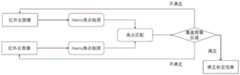
第三步:原图校正:输入上一步得到的匹配的左右角点以及红外双目相机各自内参和原来的外参,计算左右两图的角点经过去畸校正后的坐标。流程如图3所示。Step 3: Correction of the original image: Input the matching left and right corner points obtained in the previous step and the respective internal parameters and original external parameters of the infrared binocular camera, and calculate the coordinates of the corner points of the left and right images after dedistortion correction. The process is shown in Figure 3.
步骤3)中原图校正,具体包括以下步骤:Step 3) Correction of the original image, which specifically includes the following steps:
3-1)计算匹配的左右角点
像素坐标系以图片的左上角为原点,其x轴和y轴分别与图像坐标系的x轴和y轴平行。像素坐标系的单位是像素,像素是图像显示的基本且不可分割的单位。正规坐标系以相机的光心作为图像坐标系的原点,且将光心到图像平面的距离缩放到1。像素坐标与正规坐标的关系如下:The pixel coordinate system takes the upper left corner of the image as the origin, and its x-axis and y-axis are parallel to the x-axis and y-axis of the image coordinate system, respectively. The unit of the pixel coordinate system is pixel, which is the basic and indivisible unit of image display. The normal coordinate system takes the optical center of the camera as the origin of the image coordinate system, and scales the distance from the optical center to the image plane to 1. The relationship between pixel coordinates and normal coordinates is as follows:
u=KXu=KX

其中,


X=K-1uX=K-1 u
对于每一对左右相机匹配角点


其中,


3-2)去除图像畸变:根据左右图像角点的正规坐标和左右相机各自的畸变系数来计算出左右图像角点去畸变后的正规坐标。3-2) Remove image distortion: According to the normal coordinates of the left and right image corner points and the respective distortion coefficients of the left and right cameras, the normal coordinates of the left and right image corner points after the distortion are calculated.
由于镜头生产工艺的限制,实际情况下的镜头会存在一些失真现象导致非线性的畸变,可大致分为径向畸变和切向畸变。Due to the limitations of the lens production process, there will be some distortion phenomena in the actual lens that lead to nonlinear distortion, which can be roughly divided into radial distortion and tangential distortion.
图像径向畸变是图像像素点以畸变中心为中心点,沿着径向产生的位置偏差,从而导致图像中所成的像发生形变。径向畸变的大致表述如下:Image radial distortion is the positional deviation of the image pixel points with the distortion center as the center point along the radial direction, which causes the image formed in the image to deform. The approximate expression of radial distortion is as follows:
xd=x(1+k1r2+k2r4+k3r6)xd =x(1+k1 r2 +k2 r4 +k3 r6 )
yd=y(1+k1r2+k2r4+k3r6)yd =y(1+k1 r2 +k2 r4 +k3 r6 )
其中,r2=x2+y2,k1、k2、k3为径向畸变参数。Wherein, r2 =x2 +y2 , and k1 , k2 , and k3 are radial distortion parameters.
切向畸变是由于摄像机制造上的缺陷使得透镜本身与图像平面不平行而产生的,可定量描述为:Tangential distortion is caused by defects in camera manufacturing that make the lens itself not parallel to the image plane, which can be quantitatively described as:
xd=x+(2p1xy+p2(r2+2x2))xd =x+(2p1 xy+p2 (r2 +2x2 ))
yd=y+(p1(r2+2y2)+2p2xy)yd =y+(p1 (r2 +2y2 )+2p2 xy)
其中,p1、p2为切向畸变系数。Among them, p1 and p2 are tangential distortion coefficients.
综上,畸变前后的坐标关系如下:In summary, the coordinate relationship before and after distortion is as follows:
xd=x(1+k1r2+k2r4+k3r6)+(2p1xy+p2(r2+2x2))xd =x(1+k1 r2 +k2 r4 +k3 r6 )+(2p1 xy+p2 (r2 +2x2 ))
yd=y(1+k1r2+k2r4+k3r6)+(p1(r2+2y2)+2p2xy)yd =y(1+k1 r2 +k2 r4 +k3 r6 )+(p1 (r2 +2y2 )+2p2 xy)
其中,(x,y)是理想状态下的正规坐标,(xd,yd)是实际带有畸变的正规坐标。我们以(xd,yd) 作为(x,y)的初值,迭代计算若干次(例如20次)得到实际的(x,y)。Among them, (x, y) is the normal coordinate in the ideal state, and (xd , yd ) is the actual normal coordinate with distortion. We take (xd , yd ) as the initial value of (x, y), and iteratively calculate several times (for example, 20 times) to get the actual (x, y).
3-3)根据原来两相机的旋转关系将左右两图旋转:已知原来左右相机之间的旋转矩阵R 和平移向量t,使得3-3) Rotate the left and right images according to the rotation relationship of the original two cameras: the rotation matrix R and translation vector t between the original left and right cameras are known, so that
Xr=RXl+tXr =RXl +t
其中,Xl表示左相机的正规坐标,Xr表示右相机的正规坐标。将左图旋转R正方向一半的角度,将右图旋转R反方向一半的角度。Among them, Xl represents the normal coordinates of the left camera, and Xr represents the normal coordinates of the right camera. Rotate the left image by half the angle in the positive direction of R, and rotate the right image by half the angle in the opposite direction of R.
对于上一步得到的每一对去畸变之后的左右角点


3-4)根据公式u=KX将去畸旋转后的图像还原至像素坐标系。根据上一步更新的左右角点


第四步:判断角点覆盖区域:将图像分成m*n个格子,如果角点覆盖到所有格子,则进行下一步,否则继续拍摄图像,提取角点。Step 4: Determine the corner coverage area: Divide the image into m*n grids, if the corners cover all grids, proceed to the next step, otherwise continue to capture images and extract corners.
第五步:修正标定结果:使用所有角点的图像坐标来计算校正之后的两相机之间的位置关系,然后与原来的外参相叠加。Step 5: Correct the calibration result: Use the image coordinates of all corners to calculate the positional relationship between the two cameras after correction, and then superimpose with the original external parameters.
步骤5)中修正外参结果,具体包括以下步骤:Correction of external parameter results in step 5) specifically includes the following steps:
5-1)根据左右两图的角点对坐标以及左右相机的内参矩阵来求解基础矩阵F和本质矩阵 E:左右对应像素点对ul、ur和基础矩阵F的关系是:5-1) Solve the basic matrix F and the essential matrix E according to the coordinates of the corner points of the left and right images and the internal parameter matrix of the left and right cameras: the relationship between the left and right corresponding pixel pairsul ,ur and the basic matrix F is:

使用随机抽样一致性(RANSAC)对点对做进一步筛选,之后将对应点坐标代入上式,构建齐次线性方程组求解F。Use random sampling consistency (RANSAC) to further screen the point pairs, and then substitute the coordinates of the corresponding points into the above formula to construct a homogeneous linear equation system to solve F.
基础矩阵和本质矩阵的关系是:The relationship between the fundamental matrix and the essential matrix is:

其中,Kl、Kr分别是左右相机的内参矩阵。Among them, Kl and Kr are the internal parameter matrices of the left and right cameras, respectively.
5-2)从本质矩阵分解出校正之后左右相机旋转和平移关系:本质矩阵E与旋转R和平移 t的关系如下:5-2) Decompose the rotation and translation relationship of the left and right cameras after correction from the essential matrix: the relationship between the essential matrix E and the rotation R and translation t is as follows:
E=[t]×RE=[t]× R
其中[t]×表示t的叉乘矩阵。where [t]× represents the cross-product matrix of t.
将E做奇异值分解,得Do singular value decomposition of E, we get

定义两个矩阵define two matrices


所以E可以写成以下两种形式So E can be written in the following two forms
(1)E=UZUTUWVT(1) E=UZUT UWVT
令[t]×=UZUT,R=UWVTLet [t ]× = UZUT , R = UWVT
(2)E=-UZUTUWTVT(2) E=-UZUT UWT VT
令[t]×=-UZUT,R=UWTVTLet [t ]× = -UZUT , R = UWT VT
得到四对R和t,选取具有三维意义的解。Four pairs of R and t are obtained, and a solution with three-dimensional significance is selected.
5-3)将分解出的旋转和平移关系叠加到原来的外参里面。5-3) Superimpose the decomposed rotation and translation relationship into the original external parameter.
记去畸变前的旋转矩阵为R0,平移向量为t0=(tx,ty,tz)T;上一步计算出的旋转矩阵为R,平移向量为t=(t′x,t′y,t′z)T。则新的Rnew和tnew如下Note that the rotation matrix before distortion is R0 , and the translation vector is t0 =(tx ,ty , tz )T ; the rotation matrix calculated in the previous step is R, and the translation vector is t = (t′x , t ′y ,t′z )T . Then the new Rnew and tnew are as follows


还需要将tnew乘一个系数,使得tnew在x方向上的分量
本发明的有益效果是:The beneficial effects of the present invention are:
本发明解决了由于温湿度、震动等因素造成红外双目相机位置关系的改变。具有速度快、结果精确、操作简单等优点。The invention solves the change of the positional relationship of the infrared binocular camera caused by factors such as temperature, humidity, vibration and the like. It has the advantages of fast speed, accurate results and simple operation.
附图说明Description of drawings
图1为整体流程示意图。Figure 1 is a schematic diagram of the overall flow.
图2为Harris角点条件判断示意图。FIG. 2 is a schematic diagram of Harris corner condition judgment.
图3为双目校正流程示意图。FIG. 3 is a schematic diagram of a binocular calibration process.
图4(a)为分块匹配的左图示意图。Figure 4(a) is a schematic diagram on the left of block matching.
图4(b)为分块匹配的右图示意图。Figure 4(b) is a schematic diagram on the right of block matching.
具体实施方式Detailed ways
本发明旨在解决由于温湿度、震动等因素造成红外双目相机位置关系的改变。结合附图及实施例详细说明如下:The invention aims to solve the change of the positional relationship of the infrared binocular camera due to factors such as temperature and humidity, vibration and the like. The detailed description is as follows in conjunction with the accompanying drawings and embodiments:
基于Harris角点互信息匹配的立体相机动态标定算法,包括下列步骤:The dynamic calibration algorithm of stereo camera based on Harris corner mutual information matching includes the following steps:
第一步:Harris角点检测:使用红外双目相机拍摄场景图像,并在红外图像上检测Harris 角点以待匹配;Step 1: Harris corner detection: use an infrared binocular camera to capture a scene image, and detect Harris corners on the infrared image to be matched;
第一步中Harris角点检测,具体包括以下步骤:Harris corner detection in the first step includes the following steps:
1-3)使用左右相机拍摄图像,获取左右图,分别在左右图上进行角点检测;1-3) Use the left and right cameras to capture images, obtain the left and right images, and perform corner detection on the left and right images respectively;
1-4)为图像上的每一个像素点构建梯度矩阵M;1-4) Construct a gradient matrix M for each pixel on the image;
矩阵M计算方法如下:The calculation method of matrix M is as follows:
计算图像I在x方向和y方向上的梯度图像:Calculate the gradient image of image I in the x and y directions:


其中

1-3)根据每一个像素点的矩阵M来判断该像素点是否为角点;1-3) according to the matrix M of each pixel, judge whether this pixel is a corner;
使用一个值R来描述该点的角点响应,然后通过阈值σ1和σ2来判断该点是角点,角点响应值R=det(M)-k*trace(M)2,其中det(M)表示矩阵M对应的行列式的值,trace(M)表示矩阵M的迹,即:Use a value R to describe the corner response of the point, and then judge that the point is a corner through the thresholds σ1 and σ2, the corner response value R=det(M)-k*trace(M)2, where det(M ) represents the value of the determinant corresponding to the matrix M, and trace(M) represents the trace of the matrix M, namely:
det(M)=λ1*λ2det(M)=λ1*λ2
trace(M)=λ1+λ2trace(M)=λ1+λ2
其中k是常数,一般取0.04~0.06where k is a constant, generally taken from 0.04 to 0.06
当|R|<σ1时,该区域是平面;When |R|<σ1, the region is a plane;
当R<0时,该区域是直线;When R<0, the area is a straight line;
当R>σ2时,该区域是角点;When R>σ2, the area is a corner;
1-4)记左图的Harris角点集为

第二步:基于互信息的角点匹配:输入左右灰度图像以及上一步得到的左右图像的角点集

2-1)将左图像和右图像都分为m×n个块;对于左图每一个角点
2-2)找到


计算


2-3)如果

F(sfirst,ssecond)≥t2F(sfirst ,ssecond )≥t2
则保留该匹配,取

按照该规则筛选之后,再按照步骤2-2)~2-3)匹配


2-4)以左图角点


2-5)以对应右图整数像素角点


2-6)得到最终的匹配点对为
第三步:原图校正:Step 3: Correction of the original image:
输入上一步得到的匹配的左右角点以及红外双目相机各自内参和原来的外参,计算左右两图的角点经过去畸校正后的坐标;Input the matching left and right corner points obtained in the previous step and the respective internal parameters and original external parameters of the infrared binocular camera, and calculate the coordinates of the corner points of the left and right images after dedistortion correction;
第三步中原图校正,具体包括以下步骤:In the third step, the original image correction includes the following steps:
3-1)计算匹配的左右角点
对于每一对左右相机匹配角点


其中,


3-2)去除图像畸变:根据左右图像角点的正规坐标和左右相机各自的畸变系数来计算出左右图像角点去畸变后的正规坐标;3-2) Remove image distortion: According to the normal coordinates of the left and right image corner points and the respective distortion coefficients of the left and right cameras, the normal coordinates of the left and right image corner points after the distortion are calculated;
以(xd,yd)作为(x,y)的初值,迭代计算若干次得到实际的(x,y);Take (xd , yd ) as the initial value of (x, y), and iteratively calculate several times to get the actual (x, y);
3-3)根据原来两相机的旋转关系将左右两图旋转:已知原来左右相机之间的旋转矩阵R 和平移向量t,使得3-3) Rotate the left and right images according to the rotation relationship of the original two cameras: the rotation matrix R and translation vector t between the original left and right cameras are known, so that
Xr=RXl+tXr =RXl +t
其中,Xl表示左相机的正规坐标,Xr表示右相机的正规坐标;将左图旋转R正方向一半的角度,将右图旋转R反方向一半的角度;Among them, Xl represents the normal coordinates of the left camera, and Xr represents the normal coordinates of the right camera; rotate the left image by half the angle in the positive direction of R, and rotate the right image by half the angle in the reverse direction of R;
对于上一步得到的每一对去畸变之后的左右角点


3-4)根据公式u=KX将去畸旋转后的图像还原至像素坐标系;根据上一步更新的左右角点


第四步:判断角点覆盖区域:将图像分成m*n个格子,如果角点覆盖到所有格子,则进行下一步,否则继续拍摄图像,提取角点;Step 4: Determine the corner coverage area: Divide the image into m*n grids, if the corners cover all grids, proceed to the next step, otherwise continue to capture images and extract corners;
第五步:修正标定结果:使用所有角点的图像坐标来计算校正之后的两相机之间的位置关系,然后与原来的外参相叠加;Step 5: Correct the calibration result: use the image coordinates of all corner points to calculate the positional relationship between the two cameras after correction, and then superimpose with the original external parameters;
步骤5)中修正外参结果,具体包括以下步骤:Correction of external parameter results in step 5) specifically includes the following steps:
5-1)使用随机抽样一致性(RANSAC)对点对做进一步筛选,之后将对应点坐标代入上式,构建齐次线性方程组求解F;5-1) Use random sampling consistency (RANSAC) to further screen the point pairs, and then substitute the coordinates of the corresponding points into the above formula to construct a homogeneous linear equation system to solve F;
基础矩阵和本质矩阵的关系是:The relationship between the fundamental matrix and the essential matrix is:

其中,Kl、Kr分别是左右相机的内参矩阵;Among them, Kl and Kr are the internal parameter matrices of the left and right cameras respectively;
5-2)从本质矩阵分解出校正之后左右相机旋转和平移关系:本质矩阵E与旋转R和平移 t的关系如下:5-2) Decompose the rotation and translation relationship of the left and right cameras after correction from the essential matrix: the relationship between the essential matrix E and the rotation R and translation t is as follows:
E=[t]×RE=[t]× R
其中[t]×表示t的叉乘矩阵;Where [t]× represents the cross product matrix of t;
将E做奇异值分解,得Do singular value decomposition of E, we get

定义两个矩阵define two matrices


所以E可以写成以下两种形式So E can be written in the following two forms
(1)E=UZUTUWVT(1) E=UZUT UWVT
令[t]×=UZUT,R=UWVTLet [t ]× = UZUT , R = UWVT
(2)E=-UZUTUWTVT(2) E=-UZUT UWT VT
令[t]×=-UZUT,R=UWTVTLet [t ]× = -UZUT , R = UWT VT
得到四对R和t,选取具有三维意义的解;Four pairs of R and t are obtained, and the solution with three-dimensional meaning is selected;
5-3)将分解出的旋转和平移关系叠加到原来的外参里面;5-3) Superimpose the decomposed rotation and translation relationship into the original external parameter;
去畸变前的旋转矩阵R0和平移向量t0Rotation matrix R0 and translation vector t0 before dewarping

t0=[-335.5808 1.5591 -0.4805]Tt0 =[-335.5808 1.5591 -0.4805]T
上一步计算出的旋转矩阵为R′和平移向量为t′The rotation matrix calculated in the previous step is R' and the translation vector is t'

t′=[-1.0000 -0.0021 -0.0042]Tt′=[-1.0000 -0.0021 -0.0042]T
新的Rnew和tnewnew Rnew and tnew

tnew=[-335.5808 -2.1795 0.5585]T。tnew = [-335.5808 -2.1795 0.5585]T .
Claims (3)


Priority Applications (1)
| Application Number | Priority Date | Filing Date | Title |
|---|---|---|---|
| CN201911152551.9ACN110910456B (en) | 2019-11-22 | 2019-11-22 | Stereo camera dynamic calibration method based on Harris corner mutual information matching |
Applications Claiming Priority (1)
| Application Number | Priority Date | Filing Date | Title |
|---|---|---|---|
| CN201911152551.9ACN110910456B (en) | 2019-11-22 | 2019-11-22 | Stereo camera dynamic calibration method based on Harris corner mutual information matching |
Publications (2)
| Publication Number | Publication Date |
|---|---|
| CN110910456A CN110910456A (en) | 2020-03-24 |
| CN110910456Btrue CN110910456B (en) | 2020-09-29 |
Family
ID=69818903
Family Applications (1)
| Application Number | Title | Priority Date | Filing Date |
|---|---|---|---|
| CN201911152551.9AActiveCN110910456B (en) | 2019-11-22 | 2019-11-22 | Stereo camera dynamic calibration method based on Harris corner mutual information matching |
Country Status (1)
| Country | Link |
|---|---|
| CN (1) | CN110910456B (en) |
Families Citing this family (7)
| Publication number | Priority date | Publication date | Assignee | Title |
|---|---|---|---|---|
| CN113766209B (en)* | 2020-05-29 | 2024-04-30 | 上海汉时信息科技有限公司 | Camera offset processing method and device |
| CN113450416B (en)* | 2020-06-15 | 2024-03-15 | 天津工业大学 | A TCSC method applied to stereo calibration of trinocular cameras |
| CN113284189B (en)* | 2021-05-12 | 2024-07-19 | 深圳市格灵精睿视觉有限公司 | Distortion parameter calibration method, device, equipment and storage medium |
| CN113409399B (en)* | 2021-06-10 | 2023-04-11 | 武汉库柏特科技有限公司 | Dual-camera combined calibration method, system and device |
| CN114862759A (en)* | 2022-03-29 | 2022-08-05 | 扬州瑞控汽车电子有限公司 | A high-precision corner detection method and system for telephoto camera calibration |
| CN115984819A (en)* | 2022-10-18 | 2023-04-18 | 澳克诺(上海)汽车科技有限公司 | Method, device, vehicle-mounted equipment and medium for parking space measurement based on binocular camera |
| CN118885728B (en)* | 2024-07-29 | 2025-03-28 | 广州艾目易科技有限公司 | Infrared binocular camera temperature change compensation calculation method, device, equipment and medium |
Family Cites Families (6)
| Publication number | Priority date | Publication date | Assignee | Title |
|---|---|---|---|---|
| KR100755450B1 (en)* | 2006-07-04 | 2007-09-04 | 중앙대학교 산학협력단 | 3D reconstruction apparatus and method using planar homography |
| CN101419705B (en)* | 2007-10-24 | 2011-01-05 | 华为终端有限公司 | Video camera demarcating method and device |
| CN102509304A (en)* | 2011-11-24 | 2012-06-20 | 江南大学 | Intelligent optimization-based camera calibration method |
| EP2660776A1 (en)* | 2012-05-01 | 2013-11-06 | Universität Bern | Image distortion correction and robust phantom detection |
| CN109064516B (en)* | 2018-06-28 | 2021-09-24 | 北京航空航天大学 | A camera self-calibration method based on absolute quadratic image |
| CN110456330B (en)* | 2019-08-27 | 2021-07-09 | 中国人民解放军国防科技大学 | A method and system for automatic calibration of external parameters between camera and lidar without target |
- 2019
- 2019-11-22CNCN201911152551.9Apatent/CN110910456B/enactiveActive
Also Published As
| Publication number | Publication date |
|---|---|
| CN110910456A (en) | 2020-03-24 |
Similar Documents
| Publication | Publication Date | Title |
|---|---|---|
| CN110910456B (en) | Stereo camera dynamic calibration method based on Harris corner mutual information matching | |
| CN110969670B (en) | A dynamic stereo calibration method for multispectral cameras based on salient features | |
| CN110969667B (en) | Multispectral Camera Extrinsic Self-Correction Algorithm Based on Edge Feature | |
| CN110969668B (en) | Stereo calibration algorithm of long-focus binocular camera | |
| CN110969669B (en) | Visible light and infrared camera combined calibration method based on mutual information registration | |
| CN111080709B (en) | Self-calibration Algorithm for Multispectral Stereo Camera Based on Trajectory Feature Registration | |
| CN110956661B (en) | Method for calculating dynamic pose of visible light and infrared camera based on bidirectional homography matrix | |
| CN110880191B (en) | Infrared stereo camera dynamic external parameter calculation method based on histogram equalization | |
| WO2021017588A1 (en) | Fourier spectrum extraction-based image fusion method | |
| CN110992409A (en) | A dynamic registration algorithm for multispectral stereo cameras based on Fourier transform registration | |
| CN106023108A (en) | Image defogging algorithm based on boundary constraint and context regularization | |
| Hsu et al. | Object detection using structure-preserving wavelet pyramid reflection removal network | |
| CN115375581A (en) | Dynamic visual event stream noise reduction effect evaluation method based on event time-space synchronization | |
| CN117611456A (en) | Atmospheric turbulence image restoration method and system based on multiscale generation countermeasure network | |
| CN113763261A (en) | Real-time detection method for far and small targets under sea fog meteorological condition | |
| CN110910457B (en) | Multispectral three-dimensional camera external parameter calculation method based on angular point characteristics | |
| CN114018214A (en) | A Binocular Subpixel Ranging Method for Markers Based on Hardware Acceleration System | |
| CN116433822B (en) | Neural radiation field training method, device, equipment and medium | |
| CN114066786A (en) | A Fusion Method of Infrared and Visible Light Images Based on Sparse and Filter | |
| CN113962904B (en) | Method for filtering and denoising hyperspectral image | |
| CN116168066A (en) | Building three-dimensional point cloud registration preprocessing method based on data analysis | |
| CN112598777A (en) | Haze fusion method based on dark channel prior | |
| Xu et al. | Turbulent-image restoration based on a compound multibranch feature fusion network | |
| CN111462240A (en) | A target localization method based on multi-monocular vision fusion | |
| Xu et al. | Application of discrete mathematical model in edge distortion correction of moving image |
Legal Events
| Date | Code | Title | Description |
|---|---|---|---|
| PB01 | Publication | ||
| PB01 | Publication | ||
| SE01 | Entry into force of request for substantive examination | ||
| SE01 | Entry into force of request for substantive examination | ||
| GR01 | Patent grant | ||
| GR01 | Patent grant |