CN110895792A - Image splicing method and device - Google Patents
Image splicing method and deviceDownload PDFInfo
- Publication number
- CN110895792A CN110895792ACN201911373568.7ACN201911373568ACN110895792ACN 110895792 ACN110895792 ACN 110895792ACN 201911373568 ACN201911373568 ACN 201911373568ACN 110895792 ACN110895792 ACN 110895792A
- Authority
- CN
- China
- Prior art keywords
- sub
- area
- function
- region
- outgoing
- Prior art date
- Legal status (The legal status is an assumption and is not a legal conclusion. Google has not performed a legal analysis and makes no representation as to the accuracy of the status listed.)
- Granted
Links
Images


Classifications
- G—PHYSICS
- G06—COMPUTING OR CALCULATING; COUNTING
- G06T—IMAGE DATA PROCESSING OR GENERATION, IN GENERAL
- G06T3/00—Geometric image transformations in the plane of the image
- G06T3/40—Scaling of whole images or parts thereof, e.g. expanding or contracting
- G06T3/4038—Image mosaicing, e.g. composing plane images from plane sub-images
Landscapes
- Physics & Mathematics (AREA)
- General Physics & Mathematics (AREA)
- Engineering & Computer Science (AREA)
- Theoretical Computer Science (AREA)
- Length Measuring Devices By Optical Means (AREA)
Abstract
Translated fromChinese
Description
Translated fromChinese技术领域technical field
本发明涉及图像拼接技术,尤其涉及一种图像拼接方法及装置。The invention relates to image stitching technology, in particular to an image stitching method and device.
背景技术Background technique
在光学成像中,宽视场和高分辨率是一对需要平衡的指标,一般情况下高分辨率意味着有限的成像视场。在天文成像、显微成像等实际应用中,常需要在保证高分辨率的情况下实现大视场成像。为此,一个直接的思路是获取多幅高分辨率的小视场图像然后进行拼接。然而实验中获得的多幅图像会存在诸如相对位置偏差、基准相位随机起伏等问题。经典的图像配准方法多是针对强度图像而设计,一般通过计算互相关峰值位置来确定图像间的相对位置偏移。当互相关函数出现多峰时该方法失效,此外该方法假定均匀的物体照明,对检测器的噪声比较敏感。另一种图像对准方法是通过计算两幅图像的互相关功率谱来定位峰值。频域方法相对于空间域的方法具有高的计算速度和低的噪声敏感性。第三种方法是计算两幅图像统计熵值的交互信息方法,其优点是适用于不同模式采集图像的融合。上述三种方法的共同局限是都要求图像具有相似的强度分布,或至少具有强度统计相关特征;只适用于强度像的配准拼接,很少考虑不同图像的随机基准相位问题。In optical imaging, wide field of view and high resolution are a pair of indicators that need to be balanced. In general, high resolution means a limited imaging field of view. In practical applications such as astronomical imaging and microscopic imaging, it is often necessary to achieve large-field imaging while ensuring high resolution. To this end, a direct idea is to acquire multiple high-resolution images of small field of view and then stitch them together. However, the multiple images obtained in the experiment will have problems such as relative position deviation and random fluctuation of the reference phase. The classical image registration methods are mostly designed for intensity images, and generally determine the relative position offset between images by calculating the cross-correlation peak position. This method fails when the cross-correlation function has multiple peaks. Furthermore, this method assumes uniform illumination of the object and is sensitive to detector noise. Another image alignment method is to locate peaks by calculating the cross-correlation power spectrum of the two images. Frequency domain methods have high computational speed and low noise sensitivity relative to spatial domain methods. The third method is the mutual information method of calculating the statistical entropy value of two images, which has the advantage of being suitable for the fusion of images collected in different modes. The common limitation of the above three methods is that they all require images to have similar intensity distributions, or at least to have intensity statistical correlation characteristics; they are only suitable for the registration and splicing of intensity images, and rarely consider the random reference phase of different images.
强度图像反映了物体吸收对照明光强的调制能力。对于吸收效应很弱的透明物体,获得的强度图像的对比度会很低,仅能提供很有限的物体结构信息。数字全息等相位敏感显微成像技术允许获取物体的复振幅透过率函数,包括损耗以及光波通过物体时经历的时延引入的相位信息。以数字全息为例,为了在不影响成像分辨率的情况下扩大视场,常采用移动物体记录多幅全息图,然后将重构获得的多幅物体复振幅分布进行拼接的方法。另外,为了提高分辨率,也可以采用多倾斜角度照明,或以亚像素距离移动图像传感器采集多幅全息图的方法实现。上述的空域或频域互相关、交互信息最大化的图像拼接方法都假定照明光是均匀一致的,然而实际实验中能获得的物波函数通常都叠加有照明光场的信息。在照明光场非均匀的情况下,拼接后获得的物体分布存在有强的照明伪影残留。The intensity image reflects the ability of the object to absorb the modulation of the illumination intensity. For transparent objects with weak absorption effects, the obtained intensity images will have low contrast and only provide very limited information on the object structure. Phase-sensitive microscopy imaging techniques such as digital holography allow the acquisition of complex-amplitude transmittance functions of an object, including loss and phase information introduced by the time delay experienced by light waves as they pass through the object. Taking digital holography as an example, in order to expand the field of view without affecting the imaging resolution, a method of recording multiple holograms with a moving object and then splicing the complex amplitude distributions of the multiple objects obtained by reconstruction is often used. In addition, in order to improve the resolution, it can also be realized by using multi-inclined angle illumination, or by moving the image sensor at sub-pixel distances to collect multiple holograms. The above-mentioned image stitching methods for cross-correlation and mutual information maximization in the spatial or frequency domains all assume that the illumination light is uniform. In the case of non-uniform illumination light field, the distribution of objects obtained after splicing has strong residual illumination artifacts.
传统的图像拼接方法多针对强度图像。受波前测量技术的限制,获得的波前场函数的相位包含一个随机的常数偏移量。该偏离量在不同的测量中不一致。对非均匀照明,测量得到的波前包含照明光波的结构信息,从而导致拼接后物体有强的伪影残留。Traditional image stitching methods are mostly aimed at intensity images. Limited by the wavefront measurement technique, the phase of the obtained wavefront field function contains a random constant offset. This amount of deviation is not consistent across measurements. For non-uniform illumination, the measured wavefront contains information about the structure of the illumination light wave, resulting in strong artifacts remaining on objects after splicing.
发明内容SUMMARY OF THE INVENTION
本发明提供一种图像拼接方法及装置,以实现提出一种通用的波前拼接方法,来提高图像拼接的精度,以实现在保持高分辨率的同时获得大视场。The present invention provides an image stitching method and device, so as to provide a general wavefront stitching method to improve the accuracy of image stitching, so as to achieve a large field of view while maintaining high resolution.
第一方面,本发明提供一种图像拼接方法,包括:In a first aspect, the present invention provides an image stitching method, comprising:
提供初始的物体函数估计;provide initial object function estimates;
根据物体子区域出波函数更新所述物体函数估计;其中,所述物体子区域出波函数为照明光束照射到待测物体的第j个子区域位置后的出射光波函数;j为正整数;The estimation of the object function is updated according to the wave function of the object sub-region; wherein, the wave function of the object sub-region is the outgoing light wave function after the illumination beam irradiates the position of the j-th sub-region of the object to be measured; j is a positive integer;
获取出波子区域位置误差,并根据当前子区域位置和所述出波子区域位置误差获得更新的子区域位置。The position error of the outgoing sub-area is obtained, and the updated sub-area position is obtained according to the current sub-area position and the position error of the outgoing sub-area.
可选地,根据物体子区域出波函数更新所述物体函数估计包括:Optionally, updating the object function estimate according to the object sub-region wave function includes:
获取物体子区域的出波函数;Get the wave function of the sub-region of the object;
在物体出波平面施加交叠约束从而更新所述物体函数估计。The object function estimate is updated by applying overlapping constraints on the object outgoing plane.
可选地,获取出波子区域位置误差,并根据当前子区域位置和所述出波子区域位置误差获得更新的子区域位置包括:Optionally, obtaining the position error of the outgoing sub-area, and obtaining the updated sub-area position according to the current sub-area position and the position error of the outgoing sub-area includes:
根据当前物体函数估计和本次迭代中更新获得的物体函数估计的互相关峰获取所述出波子区域位置误差;Obtain the position error of the outgoing sub-region according to the current object function estimation and the cross-correlation peak of the object function estimation updated in this iteration;
根据当前所述子区域位置和所述出波子区域位置误差获得更新的子区域位置。The updated sub-area position is obtained according to the current sub-area position and the outgoing sub-area position error.
可选地,还包括:Optionally, also include:
提供初始的照明光波函数估计,并根据物体子区域出波函数,通过施加交叠约束的方式更新照明光波函数估计。Provide an initial estimate of the illumination light wave function, and update the illumination light wave function estimate by applying overlapping constraints according to the wave function of the sub-region of the object.
可选地,还包括:Optionally, also include:
判断是否完成了所有的子区域位置的计算;Determine whether the calculation of all sub-region positions is completed;
在未完成所有的子区域位置计算时,进行下一子区域位置的计算;When all sub-area position calculations are not completed, the calculation of the next sub-area position is performed;
在完成所有的子区域位置的计算后,After completing the calculation of all sub-region positions,
判断是否满足预设迭代终止条件,在不符合所述预设迭代终止条件时进行下一次迭代计算,在满足所述预设迭代终止条件时,输出拼接的物体函数和照明函数。It is judged whether the preset iteration termination condition is met, and the next iteration calculation is performed when the preset iteration termination condition is not met, and the spliced object function and lighting function are output when the preset iteration termination condition is met.
第二方面,本发明提供一种图像拼接装置,包括:In a second aspect, the present invention provides an image splicing device, comprising:
初始函数获取模块,用于提供初始的物体函数估计;The initial function acquisition module is used to provide the initial object function estimation;
物体函数估计更新模块,用于根据物体子区域出波函数更新所述物体函数估计;其中,所述物体子区域出波函数为照明光束照射到待测物体的第j个子区域位置后的出射光波函数;j为正整数;The object function estimation updating module is used to update the object function estimation according to the wave function of the sub-region of the object; wherein, the wave function of the sub-region of the object is the outgoing light wave after the illumination beam irradiates the position of the j-th sub-region of the object to be measured. function; j is a positive integer;
子区域位置更新模块,用于获取出波子区域位置误差,并根据当前子区域位置和所述出波子区域位置误差获得更新的子区域位置。The sub-area position update module is used to obtain the position error of the outgoing sub-area, and obtain the updated sub-area position according to the current sub-area position and the position error of the outgoing sub-area.
可选地,物体函数估计更新模块包括:Optionally, the object function estimation update module includes:
出波测量单元,用于获取物体子区域的出波函数;The outgoing wave measurement unit is used to obtain the outgoing wave function of the sub-region of the object;
物体函数估计更新单元,用于在物体出波平面施加交叠约束从而更新所述物体函数估计。The object function estimation updating unit is configured to impose overlapping constraints on the object wave exit plane to update the object function estimation.
可选地,所述子区域位置更新模块包括:Optionally, the sub-region location update module includes:
位置误差获取单元,用于根据当前物体函数估计和本次迭代中更新获得的物体函数估计的互相关峰获取所述出波子区域位置误差;a position error obtaining unit, configured to obtain the position error of the outgoing sub-region according to the current object function estimation and the cross-correlation peak of the object function estimation updated in this iteration;
子区域位置更新单元,用于根据当前子区域位置和所述出波子区域位置误差获得更新的子区域位置。A sub-area position updating unit, configured to obtain an updated sub-area position according to the current sub-area position and the position error of the outgoing sub-area.
可选地,还包括:Optionally, also include:
照明光波函数估计更新模块,用于提供初始的照明光波函数估计,并根据物体子区域出波函数,通过施加交叠约束的方式更新照明光波函数估计。The illuminating light wave function estimation updating module is used to provide the initial illuminating light wave function estimation, and update the illuminating light wave function estimation by applying overlapping constraints according to the outgoing wave function of the sub-region of the object.
可选地,还包括:Optionally, also include:
子区域位置判断模块,用于判断是否完成了所有的子区域位置的计算;The sub-region position judgment module is used to judge whether the calculation of all the sub-region positions is completed;
在未完成所有的子区域位置计算时,进行下一子区域位置的计算;When all sub-area position calculations are not completed, the calculation of the next sub-area position is performed;
预设迭代终止条件判断模块,用于判断是否满足预设迭代终止条件,在不符合所述预设迭代终止条件时进行下一次迭代计算,在满足所述预设迭代终止条件时,输出拼接的物体函数和照明函数。The preset iteration termination condition judgment module is used for judging whether the preset iteration termination condition is met, and when the preset iteration termination condition is not met, the next iteration calculation is performed, and when the preset iteration termination condition is met, output the spliced Object functions and lighting functions.
本发明实施例提供的图像拼接方法中,相对于现有技术中通过对多个小的强度图像进行拼接而言,同时包括强度信息和相位信息的波前拼接具有更高的拼接精度,以实现在保持高分辨率的同时获得大视场。本发明实施例还获取了图像拼接时的出波子区域位置误差,从而获取真实的拼接位置,提高了图像拼接的精确度。需要说明的是,波前拼接并非是单独地对强度信息的拼接,以及并非是单独地相位信息的拼接,而是同时对包含强度信息以及相位信息的多个子区域位置对应的物体函数(即待测物体的复振幅透过率函数)的操作,即使是一组相位包裹的复振幅波前,依然可以实现高保真拼接。In the image stitching method provided by the embodiment of the present invention, compared with the prior art by stitching multiple images with small intensity, the wavefront stitching including both intensity information and phase information has higher stitching accuracy, so as to achieve higher stitching accuracy. Get a large field of view while maintaining high resolution. The embodiment of the present invention also obtains the position error of the outgoing sub-region during image stitching, thereby obtaining the real stitching position and improving the accuracy of image stitching. It should be noted that the wavefront splicing is not the splicing of the intensity information alone, nor the splicing of the phase information alone, but the simultaneous splicing of the object functions corresponding to the positions of multiple sub-regions containing the intensity information and the phase information (that is, to be Even a set of phase-wrapped complex-amplitude wavefronts can still achieve high-fidelity splicing.
附图说明Description of drawings
图1为本发明实施例提供的一种图像拼接方法的流程示意图;1 is a schematic flowchart of an image stitching method according to an embodiment of the present invention;
图2为预放大离轴像面数字全息图记录光路示意图;Fig. 2 is a schematic diagram of a pre-amplified off-axis image plane digital hologram recording optical path;
图3为多幅数字全息图采集过程示意图;FIG. 3 is a schematic diagram of the acquisition process of multiple digital holograms;
图4为图1中步骤S12的详细方法的流程示意图;4 is a schematic flowchart of the detailed method of step S12 in FIG. 1;
图5为图1中步骤S13详细方法的流程示意图;5 is a schematic flowchart of the detailed method of step S13 in FIG. 1;
图6为本发明实施例提供的另一种图像拼接方法的流程示意图;6 is a schematic flowchart of another image stitching method provided by an embodiment of the present invention;
图7为本发明实施例提供的一种图像拼接装置的示意图;7 is a schematic diagram of an image stitching device provided by an embodiment of the present invention;
图8为图7中物体函数估计更新模块的结构示意图;Fig. 8 is the structural representation of the object function estimation updating module in Fig. 7;
图9为图7中子区域位置更新模块的结构示意图;Fig. 9 is the structural representation of the sub-region position update module in Fig. 7;
图10为本发明实施例提供的另一种图像拼接装置的示意图;10 is a schematic diagram of another image stitching device provided by an embodiment of the present invention;
图11a为第一待测物体的振幅分布图;Figure 11a is an amplitude distribution diagram of the first object to be measured;
图11b为第一照明光场的振幅分布图;FIG. 11b is an amplitude distribution diagram of the first illumination light field;
图11c为第一待测物体的相位分布图;11c is a phase distribution diagram of the first object to be measured;
图11d为第一照明光场的相位分布图;11d is a phase distribution diagram of the first illumination light field;
图11e为拼接完成后第一待测物体的的振幅分布图;Fig. 11e is the amplitude distribution diagram of the first object to be measured after the splicing is completed;
图11f为拼接完成后复原的第一照明光场的振幅分布图;Fig. 11f is the amplitude distribution diagram of the first illumination light field restored after splicing is completed;
图11g为拼接完成后第一待测物体的相位分布图;Figure 11g is the phase distribution diagram of the first object to be measured after the splicing is completed;
图11h为拼接完成后复原的第一照明光场的相位分布图;Fig. 11h is the phase distribution diagram of the first illumination light field restored after splicing is completed;
图12a为通过数字全息方法获取的第二待测物体的第一行第一列样品位置的振幅分布图;Fig. 12a is the amplitude distribution diagram of the sample position of the first row and the first column of the second object to be measured obtained by the digital holography method;
图12b为通过数字全息方法获取的第二待测物体的第一行第一列样品位置的相位分布图;Fig. 12b is the phase distribution diagram of the sample position of the first row and the first column of the second object to be measured obtained by the digital holography method;
图12c为通过数字全息方法获取的第二待测物体的第四行第四列样品位置的振幅分布图;Fig. 12c is the amplitude distribution diagram of the sample position of the fourth row and the fourth column of the second object to be measured obtained by the digital holography method;
图12d为通过数字全息方法获取的第二待测物体的第四行第四列样品位置的相位分布图;12d is a phase distribution diagram of the sample position of the fourth row and fourth column of the second object to be measured obtained by a digital holography method;
图12e为拼接完成后第二待测物体的的振幅分布图;Figure 12e is the amplitude distribution diagram of the second object to be measured after the splicing is completed;
图12f为拼接完成后第二照明光场的振幅分布图;Figure 12f is an amplitude distribution diagram of the second illumination light field after the splicing is completed;
图12g为拼接完成后第二待测物体的相位分布图;Figure 12g is the phase distribution diagram of the second object to be measured after the splicing is completed;
图12h为拼接完成后第二照明光场的相位分布图。FIG. 12h is a phase distribution diagram of the second illumination light field after the splicing is completed.
具体实施方式Detailed ways
下面结合附图和实施例对本发明作进一步的详细说明。可以理解的是,此处所描述的具体实施例仅仅用于解释本发明,而非对本发明的限定。另外还需要说明的是,为了便于描述,附图中仅示出了与本发明相关的部分而非全部结构。The present invention will be further described in detail below in conjunction with the accompanying drawings and embodiments. It should be understood that the specific embodiments described herein are only used to explain the present invention, but not to limit the present invention. In addition, it should be noted that, for the convenience of description, the drawings only show some but not all structures related to the present invention.
图1为本发明实施例提供的一种图像拼接方法的流程示意图,参考图1,图像拼接方法包括如下步骤:FIG. 1 is a schematic flowchart of an image stitching method provided by an embodiment of the present invention. Referring to FIG. 1 , the image stitching method includes the following steps:
S11、提供初始的物体函数估计。S11. Provide an initial object function estimation.
示例性地,首先产生一个代表待测物体的复振幅透过率函数(即物体函数估计)的矩阵,矩阵的大小要确保待测物体移动后照明光束仍然在待测物体的矩阵边界内。该待测物体的复振幅透过率函数的矩阵的初始振幅和相位值可任意设定。Exemplarily, a matrix representing the complex amplitude transmittance function of the object to be measured (ie, object function estimation) is first generated, and the size of the matrix is to ensure that the illumination beam remains within the matrix boundary of the object to be measured after the object to be measured moves. The initial amplitude and phase values of the matrix of the complex amplitude transmittance function of the object to be measured can be arbitrarily set.
S12、根据物体子区域出波函数更新物体函数估计。S12, update the object function estimation according to the wave function of the object sub-region.
其中,物体子区域出波函数为照明光束照射到待测物体的第j个子区域位置后的出射光波函数;j为正整数。Wherein, the outgoing wave function of the object sub-region is the outgoing light wave function after the illumination beam irradiates the position of the j-th sub-region of the object to be measured; j is a positive integer.
示例性地,由数字全息方法得到待测物体的9个子区域位置的波前(即物体子区域出波函数)作为初始信息进行图像拼接迭代计算。每个波前分布记为
S13、获取出波子区域位置误差,并根据当前子区域位置和出波子区域位置误差获得更新的子区域位置。S13: Obtain the position error of the outgoing sub-area, and obtain an updated sub-area position according to the current sub-area position and the position error of the outgoing sub-area.
本发明实施例提供的图像拼接方法中,相对于现有技术中通过对多个小的强度图像进行拼接而言,同时包括强度信息和相位信息的波前拼接具有更高的拼接精度,以实现在保持高分辨率的同时获得大视场。本发明实施例还获取了图像拼接时的出波子区域位置误差,从而获取真实的拼接位置,提高了图像拼接的精确度。需要说明的是,波前拼接并非是单独地对强度信息的拼接,以及并非是单独地相位信息的拼接,而是同时对包含强度信息以及相位信息的多个复振幅透过率函数的操作,即使是一组相位包裹的复振幅波前,依然可以实现高保真拼接。In the image stitching method provided by the embodiment of the present invention, compared with the prior art by stitching multiple images with small intensity, the wavefront stitching including both intensity information and phase information has higher stitching accuracy, so as to achieve higher stitching accuracy. Get a large field of view while maintaining high resolution. The embodiment of the present invention also obtains the position error of the outgoing sub-region during image stitching, thereby obtaining the real stitching position and improving the accuracy of image stitching. It should be noted that the wavefront splicing is not the splicing of the intensity information alone, nor the splicing of the phase information alone, but the operation of multiple complex amplitude transmittance functions including the intensity information and the phase information at the same time, Even a set of phase-wrapped complex-amplitude wavefronts can still be stitched with high fidelity.
图2为预放大离轴像面数字全息图记录光路示意图,图3为多幅数字全息图采集过程示意图,参考图2和图3,预放大离轴像面数字全息图记录系统包括第一光源1、样品2(即待测物体)、显微物镜3、第二光源4和图像传感器5(即探测器)。第一光源1发出有限大小的照明光束,并照射到样品2的第一样品位置201上,携带样品2的第一样品位置201的透过率信息的照明光束通过显微物镜3后被图像传感器5接收。同时,第二光源4发出的参考光束也被图像传感器5接收,照明光束和参考光束发生干涉,图像传感器5记录了照明光束和参考光束的干涉条纹。完成对第一样品位置201的成像后,移动样品2并使第一光源1照射到样品2的第二样品位置202,以同样的方式对第二样品位置202成像。第一样品位置201和第二样品位置202部分交叠,从而获取的第一样品位置的样品波前与第二样品位置的样品波前部分交叠。本发明实施例以两个样品位置为例进行解释说明,并非对本发明的限定。FIG. 2 is a schematic diagram of the optical path of pre-amplified off-axis image plane digital hologram recording, and FIG. 3 is a schematic diagram of the acquisition process of multiple digital holograms. Referring to FIGS. 2 and 3 , the pre-amplified off-axis image plane digital hologram recording system includes a first light source 1. The sample 2 (ie the object to be measured), the
其中,(x0,y0)是样品2所在的物平面上的笛卡尔坐标,(xm,ym)是显微物镜3所在的平面上的笛卡尔坐标,(x,y)是图像传感器5的全息图记录平面上的笛卡尔坐标,图像传感器5的全息图记录平面也是样品2通过显微物镜3成像的像面所在位置。照明光束和参考光束均为球面波,z代表系统光轴方向。照明光束垂直入射到样品2,z1是第一光源1与样品2之间的距离;z2是样品2与显微物镜3之间的距离,称为物距;z3是显微物镜3与图像传感器5之间的距离,称为像距。参考光束相对于z轴具有(xr,yr)的位置偏移。将图像传感器5采集到的数字全息图进行重构,具体过程为:先把全息图剪裁成正方形并进行傅里叶变换;截取出+1级频谱并移动到计算网格中心并补零至原正方形大小;对结果进行逆傅里叶变换,即得到样品2的复振幅分布。Among them, (x0 , y0 ) are the Cartesian coordinates on the object plane where the
图4为图1中步骤S12的详细方法的流程示意图,参考图1和图4,根据物体子区域出波函数更新物体函数估计包括:FIG. 4 is a schematic flowchart of the detailed method of step S12 in FIG. 1 . Referring to FIG. 1 and FIG. 4 , updating the object function estimation according to the wave function of the object sub-region includes:
S121、获取物体子区域的出波函数。S121 , acquiring the wave emitting function of the sub-region of the object.
S122、在物体出波平面施加交叠约束从而更新物体函数估计。S122 , applying an overlap constraint on the object wave outgoing plane to update the object function estimation.
其中,物体函数估计的更新是通过在探测面施加交叠约束实现的,交叠约束指的是,从每个子区域位置对应的衍射图案(衍射图案被物体出波平面接收)获取的物体函数在其重叠区域保持一致。Among them, the update of the object function estimation is realized by applying overlapping constraints on the detection surface. The overlapping constraints refer to the object function obtained from the diffraction pattern corresponding to the position of each sub-region (the diffraction pattern is received by the object outgoing plane) in Its overlapping area remains the same.
示例性地,更新后的物体函数估计满足:Exemplarily, the updated object function estimate satisfies:

其中,本次迭代为第m+1次迭代,上次迭代为第m次迭代。

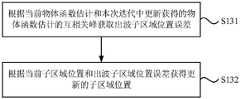
图5为图1中步骤S13详细方法的流程示意图,参考图1和图5,获取出波子区域位置误差,并根据当前子区域位置和出波子区域位置误差获得更新的子区域位置包括:FIG. 5 is a schematic flowchart of the detailed method of step S13 in FIG. 1 . Referring to FIG. 1 and FIG. 5 , the position error of the outgoing sub-area is obtained, and the updated sub-area position obtained according to the current sub-area position and the position error of the outgoing sub-area includes:
S131、根据当前物体函数估计和本次迭代中更新获得的物体函数估计的互相关峰获取出波子区域位置误差。S131. Obtain the position error of the wave sub-region according to the current object function estimation and the cross-correlation peak of the object function estimation updated in this iteration.
示例性地,出波子区域位置误差


其中,
S132、根据当前子区域位置和出波子区域位置误差获得更新的子区域位置。S132: Obtain an updated sub-area position according to the current sub-area position and the position error of the outgoing sub-area.
本申请的研究人员发现,待测物体的每个子区域位置在两次迭代之间存在微小的相对移动量,即出波子区域位置误差,即


示例性地,


图6为本发明实施例提供的另一种图像拼接方法的流程示意图,参考图6,图像拼接方法还包括:FIG. 6 is a schematic flowchart of another image stitching method provided by an embodiment of the present invention. Referring to FIG. 6 , the image stitching method further includes:
S14、提供初始的照明光波函数估计,并根据物体子区域出波函数,通过施加交叠约束的方式更新照明光波函数估计。S14 , providing an initial illumination light wave function estimation, and updating the illumination light wave function estimation by applying overlapping constraints according to the outgoing wave function of the sub-region of the object.
其中,更新光波函数估计是通过施加交叠约束实现的。该待测物体的照明光波函数矩阵(即照明光波函数估计)的初始振幅和相位值可任意设定。Among them, updating the light wave function estimation is achieved by imposing overlapping constraints. The initial amplitude and phase values of the illumination light wave function matrix of the object to be measured (ie, the estimation of the illumination light wave function) can be set arbitrarily.
示例性地,对照明光束施加交叠约束,形成更新的照明光波函数估计:Illustratively, overlapping constraints are imposed on the illumination beams, resulting in an updated estimate of the illumination light wave function:

其中,常数α2控制反馈更新的权重。Among them, the constant α2 controls the weight of the feedback update.
本发明实施例中,通过为照明光束施加交叠约束的条件,在重构待测物体的透过率函数的同时也可获得准确的照明光场的复振幅分布以及精确地确定待测物体和照明光场之间的相对位置。以实现待测物体的信息和照明光信息的分离,分别得到待测物体和照明光场的复振幅分布。可以解决非均匀照明导致拼接后的伪影残留问题。利用已知的物体子区域出波函数更新物体函数的估计,以及更新照明函数的估计(从而移除其对物体函数的影响,减少伪影),而这是在即便子区域的位置没能准确提供的时候也能实现高精度,高准确度地实现大区域物体函数的重构。在其他实施方式中,也可以不根据物体子区域出波函数更新照明光波函数估计。In the embodiment of the present invention, by imposing overlapping constraints on the illumination beams, while reconstructing the transmittance function of the object to be measured, an accurate complex amplitude distribution of the illumination light field and accurate determination of the object and the object to be measured can also be obtained. Relative position between illumination light fields. In order to realize the separation of the information of the object to be measured and the information of the illumination light, the complex amplitude distributions of the object to be measured and the illumination light field are obtained respectively. It can solve the problem of artifacts remaining after stitching caused by non-uniform lighting. Update the estimate of the object function with the known wave function of the object sub-region, and update the estimate of the lighting function (thus removing its influence on the object function and reducing artifacts), even if the position of the sub-region is not accurate When provided, it can also achieve high-precision and high-accuracy reconstruction of large-area object functions. In other embodiments, the illumination light wave function estimation may not be updated according to the object sub-region outgoing wave function.
可选地,参考图6,图像拼接方法还包括:Optionally, referring to Figure 6, the image stitching method further includes:
S15、判断是否完成了所有的子区域位置的计算;在未完成所有的子区域位置计算时,进行下一子区域位置的计算;S15, determine whether the calculation of all the sub-region positions is completed; when all the sub-region position calculations are not completed, perform the calculation of the next sub-region position;
其中,每次迭代中,每个子区域位置对应的物体函数函数估计都被更新,以提供待测物体的图像。Among them, in each iteration, the estimation of the object function function corresponding to the position of each sub-region is updated to provide an image of the object to be measured.
S16、在完成所有的子区域位置的计算后,判断是否满足预设迭代终止条件;在不符合预设迭代终止条件时进行下一次迭代计算,在满足预设迭代终止条件时,输出拼接的物体函数和照明函数。S16. After completing the calculation of all sub-region positions, determine whether the preset iteration termination condition is met; if the preset iteration termination condition is not met, perform the next iteration calculation, and when the preset iteration termination condition is met, output the spliced object function and lighting function.
其中,预设迭代终止条件比如达到预设计算次数,或者直至检测器计算得到的振幅与记录得到的第一振幅之间的差值小于预设值。Wherein, the preset iteration termination condition, for example, reaches the preset number of calculations, or until the difference between the amplitude calculated by the detector and the first amplitude recorded and obtained is smaller than the preset value.
图7为本发明实施例提供的一种图像拼接装置的示意图,用于执行上述实施例中的图像拼接方法,图像拼接装置包括初始函数获取模块11、物体函数估计更新模块12和子区域位置更新模块13。其中,初始函数获取模块11用于提供初始的物体函数估计。物体函数估计更新模块12用于根据物体子区域出波函数更新物体函数估计。其中,物体子区域出波函数为照明光束照射到待测物体的第j个子区域位置后的出射光波函数;j为正整数。子区域位置更新模块13用于获取出波子区域位置误差,并根据当前子区域位置和出波子区域位置误差获得更新的子区域位置。FIG. 7 is a schematic diagram of an image stitching apparatus provided by an embodiment of the present invention, which is used to execute the image stitching method in the above-mentioned embodiment. The image stitching apparatus includes an initial
图8为图7中物体函数估计更新模块的结构示意图,参考图7和图8,物体函数估计更新模块12包括出波测量单元121和物体函数估计更新单元122。其中,出波测量单元121用于获取物体子区域的出波函数。物体函数估计更新单元122用于在物体出波平面施加交叠约束从而更新物体函数估计。8 is a schematic structural diagram of the object function estimation updating module in FIG. 7 . Referring to FIGS. 7 and 8 , the object function
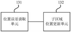
图9为图7中子区域位置更新模块的结构示意图,参考图7和图9,子区域位置更新模块13包括位置误差获取单元131和子区域位置更新单元132。其中,位置误差获取单元131用于根据当前物体函数估计和本次迭代中更新获得的物体函数估计的互相关峰获取出波子区域位置误差。子区域位置更新单元132用于根据当前子区域位置和出波子区域位置误差获得更新的子区域位置。FIG. 9 is a schematic structural diagram of the sub-region position update module in FIG. 7 . Referring to FIGS. 7 and 9 , the sub-region
图10为本发明实施例提供的另一种图像拼接装置的示意图,参考图10,图像拼接装置还包括照明光波函数估计更新模块14,照明光波函数估计更新模块14用于提供初始的照明光波函数估计,并根据物体子区域出波函数,通过施加交叠约束的方式更新照明光波函数估计。FIG. 10 is a schematic diagram of another image stitching apparatus provided by an embodiment of the present invention. Referring to FIG. 10 , the image stitching apparatus further includes an illumination light wave function
可选地,参考图10,图像拼接装置还包括子区域位置判断模块15和预设迭代终止条件判断模块16。其中,子区域位置判断模块15用于判断是否完成了所有的子区域位置的计算;在未完成所有的子区域位置计算时,进行下一子区域位置的计算。预设迭代终止条件判断模块16用于判断是否满足预设迭代终止条件,在不符合预设迭代终止条件时进行下一次迭代计算,在满足预设迭代终止条件时,输出拼接的物体函数和照明函数。Optionally, referring to FIG. 10 , the image stitching apparatus further includes a sub-region
本发明为了验证上述图像拼接方法以及图像拼接装置提高拼接精度的效果,对此作出了模拟验证和实验验证。In order to verify the effect of the above-mentioned image splicing method and the image splicing device in improving the splicing accuracy, the present invention provides simulation verification and experimental verification.
图11a为第一待测物体的振幅分布图,图11b为第一照明光场的振幅分布图,图11c为第一待测物体的相位分布图,图11d为第一照明光场的相位分布图,图11e为拼接完成后第一待测物体的的振幅分布图,图11f为拼接完成后复原的第一照明光场的振幅分布图,图11g为拼接完成后第一待测物体的相位分布图,图11h为拼接完成后复原的第一照明光场的相位分布图,参考图11a-图11h,模拟中,首先使用了具有复振幅分布的第一待测物体(即样品为第一待测物体),第一待测物体的振幅值分布在0.3到1之间,相位值分布在-π到π之间,尺寸为524×524像素。第一照明光场的振幅值是均匀“1”基础上叠加了泊松噪声,相位值为0,尺寸为256×256像素。模拟采集了7×7个扫描位置,扫描步长为23个像素再加上最大8个像素的随机波动,相邻图像的交叠率为91%。第一照明光场的位置更新和函数更新分别开始于第3次和第30次迭代,共迭代80次。拼接完成后复原的第一照明光场的相位值均匀分布在(-0.01,0.01)之间。相比原始第一待测物体和第一照明光场的图像,实现了高保真的再现和图像拼接。Fig. 11a is the amplitude distribution diagram of the first object to be measured, Fig. 11b is the amplitude distribution diagram of the first illumination light field, Fig. 11c is the phase distribution diagram of the first object to be measured, and Fig. 11d is the phase distribution diagram of the first illumination light field Fig. 11e is the amplitude distribution diagram of the first object to be measured after the splicing is completed, Fig. 11f is the amplitude distribution diagram of the first illumination light field restored after the splicing is completed, and Fig. 11g is the phase of the first object to be measured after the splicing is completed Distribution diagram, Fig. 11h is the phase distribution diagram of the restored first illumination light field after splicing, referring to Fig. 11a-Fig. 11h, in the simulation, the first object to be tested with complex amplitude distribution (that is, the sample is the first object to be tested) is used first. object to be measured), the amplitude value of the first object to be measured is distributed between 0.3 and 1, the phase value is distributed between -π and π, and the size is 524×524 pixels. The amplitude value of the first illumination light field is a uniform "1" on which Poisson noise is superimposed, the phase value is 0, and the size is 256×256 pixels. The simulations collected 7 × 7 scan positions with a scan step size of 23 pixels plus random fluctuations of up to 8 pixels, with a 91% overlap of adjacent images. The position update and function update of the first illumination light field start at the 3rd and 30th iterations, respectively, for a total of 80 iterations. The phase value of the restored first illumination light field after splicing is evenly distributed between (-0.01, 0.01). Compared with the images of the original first object to be tested and the first illumination light field, high-fidelity reproduction and image stitching are achieved.
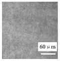
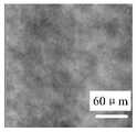
图12a为通过数字全息方法获取的第二待测物体的第一行第一列样品位置的振幅分布图,图12b为通过数字全息方法获取的第二待测物体的第一行第一列样品位置的相位分布图,图12c为通过数字全息方法获取的第二待测物体的第四行第四列样品位置的振幅分布图,图12d为通过数字全息方法获取的第二待测物体的第四行第四列样品位置的相位分布图,图12e为拼接完成后第二待测物体的的振幅分布图,图12f为拼接完成后第二照明光场的振幅分布图,图12g为拼接完成后第二待测物体的相位分布图,图12h为拼接完成后第二照明光场的相位分布图,参考图12a-图12h,实验中,使用了预放大离轴像面数字全息系统,照明光束合参考光束的光强比为1:1。显微物镜3的放大倍率为20倍。图像传感器5的像素尺寸为4.65μm×4.65μm。所使用的第二待测物体为年轮细胞生物标本样片,第二待测物体放置于一个三维平移台上,沿x0、y0两个方向移动物体采集7×7个扫描位置,步长为205个像素,相邻图像的交叠率为80%,沿z方向移动可进行调焦,保证第二待测物体成像在图像传感器5光敏面上。把数字全息方法再现获取的49个复振幅分布作为初始数据,输入到图像拼接算法中,照明光场的位置更新和函数更新分别开始于第3次和第50次迭代,共迭代200次。可见,由于照明光的信息被分离出来,因此第二待测物体信息得到更加保真的复原,存在于图12a-图12d中的杂散斜纹消失了,转移到照明光场分布中。通过对比初始输入和拼接后输出的图像位置,得到x和y两个方向的平均误差分别为43个像素和36个像素。y方向优于x方向的原因与采集方式有关,因为采集时y轴是沿单一方向进行移动扫描,而x方向是要来回两个方向进行移动扫描,平移台机械件齿轮间存在的回程误差导致该结果的产生。本发明提供了一种通用的复波前拼接方法,该方法计算复杂度适中、高效。可实现0.01像素精度拼接。和波前测量技术结合可实现高分辨率大视场成像。Fig. 12a is the amplitude distribution diagram of the sample position of the first row and the first column of the second object to be tested obtained by the digital holography method, Fig. 12b is the sample of the first row and the first column of the second object to be tested obtained by the digital holography method The phase distribution diagram of the position, Figure 12c is the amplitude distribution diagram of the sample position of the fourth row and fourth column of the second object to be measured obtained by the digital holography method, and Figure 12d is the second object to be measured obtained by the digital holography method. The phase distribution diagram of the sample position in the fourth row and the fourth column, Fig. 12e is the amplitude distribution diagram of the second object to be tested after the splicing is completed, Fig. 12f is the amplitude distribution diagram of the second illumination light field after the splicing is completed, and Fig. 12g is the splicing completed. The phase distribution diagram of the second object to be measured, Fig. 12h is the phase distribution diagram of the second illumination light field after the splicing is completed, refer to Fig. 12a-Fig. 12h, in the experiment, a pre-amplified off-axis image plane digital holography system was used to illuminate The light intensity ratio of the beam to the reference beam is 1:1. The magnification of the
注意,上述仅为本发明的较佳实施例及所运用技术原理。本领域技术人员会理解,本发明不限于这里所述的特定实施例,对本领域技术人员来说能够进行各种明显的变化、重新调整、相互结合和替代而不会脱离本发明的保护范围。因此,虽然通过以上实施例对本发明进行了较为详细的说明,但是本发明不仅仅限于以上实施例,在不脱离本发明构思的情况下,还可以包括更多其他等效实施例,而本发明的范围由所附的权利要求范围决定。Note that the above are only preferred embodiments of the present invention and applied technical principles. Those skilled in the art will understand that the present invention is not limited to the specific embodiments described herein, and various obvious changes, readjustments, combinations and substitutions can be made by those skilled in the art without departing from the protection scope of the present invention. Therefore, although the present invention has been described in detail through the above embodiments, the present invention is not limited to the above embodiments, and can also include more other equivalent embodiments without departing from the concept of the present invention. The scope is determined by the scope of the appended claims.
Claims (10)
Translated fromChineseApplications Claiming Priority (2)
| Application Number | Priority Date | Filing Date | Title |
|---|---|---|---|
| CN201910970075 | 2019-10-12 | ||
| CN2019109700755 | 2019-10-12 |
Publications (2)
| Publication Number | Publication Date |
|---|---|
| CN110895792Atrue CN110895792A (en) | 2020-03-20 |
| CN110895792B CN110895792B (en) | 2023-07-14 |
Family
ID=69789236
Family Applications (1)
| Application Number | Title | Priority Date | Filing Date |
|---|---|---|---|
| CN201911373568.7AActiveCN110895792B (en) | 2019-10-12 | 2019-12-27 | An image stitching method and device |
Country Status (1)
| Country | Link |
|---|---|
| CN (1) | CN110895792B (en) |
Cited By (3)
| Publication number | Priority date | Publication date | Assignee | Title |
|---|---|---|---|---|
| CN111968170A (en)* | 2020-08-26 | 2020-11-20 | 广东工业大学 | Online binocular vision distance measurement method based on cross-correlation time delay estimation |
| CN114612345A (en)* | 2022-04-01 | 2022-06-10 | 江苏通纺互联科技有限公司 | Light source detection method based on image processing |
| CN114677365A (en)* | 2022-04-18 | 2022-06-28 | 北京林业大学 | High-precision tree ring analysis method and system |
Citations (3)
| Publication number | Priority date | Publication date | Assignee | Title |
|---|---|---|---|---|
| US20100241396A1 (en)* | 2007-05-22 | 2010-09-23 | John Marius Rodenburg | Three dimensional imaging |
| CN105241396A (en)* | 2015-10-20 | 2016-01-13 | 北京航空航天大学 | Digital hologram-based high-precision spherical surface sub-aperture splicing fusion method |
| CN106680240A (en)* | 2016-12-14 | 2017-05-17 | 北京工业大学 | Continuous-terahertz wave double-object distance laminated imaging method |
- 2019
- 2019-12-27CNCN201911373568.7Apatent/CN110895792B/enactiveActive
Patent Citations (3)
| Publication number | Priority date | Publication date | Assignee | Title |
|---|---|---|---|---|
| US20100241396A1 (en)* | 2007-05-22 | 2010-09-23 | John Marius Rodenburg | Three dimensional imaging |
| CN105241396A (en)* | 2015-10-20 | 2016-01-13 | 北京航空航天大学 | Digital hologram-based high-precision spherical surface sub-aperture splicing fusion method |
| CN106680240A (en)* | 2016-12-14 | 2017-05-17 | 北京工业大学 | Continuous-terahertz wave double-object distance laminated imaging method |
Cited By (4)
| Publication number | Priority date | Publication date | Assignee | Title |
|---|---|---|---|---|
| CN111968170A (en)* | 2020-08-26 | 2020-11-20 | 广东工业大学 | Online binocular vision distance measurement method based on cross-correlation time delay estimation |
| CN114612345A (en)* | 2022-04-01 | 2022-06-10 | 江苏通纺互联科技有限公司 | Light source detection method based on image processing |
| CN114677365A (en)* | 2022-04-18 | 2022-06-28 | 北京林业大学 | High-precision tree ring analysis method and system |
| CN114677365B (en)* | 2022-04-18 | 2024-04-05 | 北京林业大学 | A high-precision tree ring analysis method and system |
Also Published As
| Publication number | Publication date |
|---|---|
| CN110895792B (en) | 2023-07-14 |
Similar Documents
| Publication | Publication Date | Title |
|---|---|---|
| US9116120B2 (en) | Three dimensional imaging | |
| JP6561110B2 (en) | How to identify the location of defects on a substrate | |
| KR20200000818A (en) | Method for detecting a structure of a lithography mask and device for carrying out the method | |
| US20140347672A1 (en) | Apparatus and method for quantitive phase tomography through linear scanning with coherent and non-coherent detection | |
| JP2013513823A (en) | Method and system for microscope imaging with high-speed three-dimensional structured illumination | |
| KR20210048528A (en) | Surface shape measurement device and surface shape measurement method | |
| US20110032586A1 (en) | Light microscope with novel digital method to achieve super-resolution | |
| CN110895792B (en) | An image stitching method and device | |
| TWI845952B (en) | Method for determining an imaging quality of an optical system when illuminated by illumination light within an entrance pupil to be measured | |
| CN109900356B (en) | Correlation imaging method and apparatus | |
| CN111982014A (en) | Micro-interference-based microsphere surface morphology large-field-of-view measurement method | |
| TW202232475A (en) | Optical measurement system and optical measurement method | |
| CN110927116B (en) | Method, device and system for measuring mark structure | |
| CN118883434B (en) | Scanning quantitative phase microscopy device and method based on polarization multiplexing modulation | |
| US12038569B2 (en) | High sensitivity phase microscopy imaging | |
| CN110411983B (en) | High-resolution diffraction imaging method and device | |
| CN116625269A (en) | A Method for Absolute Detection of Plane Shape of Large-aperture Optical Components | |
| US20230073901A1 (en) | Systems and methods for performing multiple-wavelength quantitative phase imaging (qpi) | |
| CN109085137B (en) | Three-dimensional imaging device and imaging method based on K-space transformation | |
| CN119618083B (en) | Displacement measuring device and displacement measuring method | |
| Guizar-Sicairos et al. | Image reconstruction by phase retrieval with transverse translation diversity | |
| CN118936346A (en) | Material photoinduced deformation coefficient measurement method and measurement system based on optical interference principle | |
| Wyant | Precision optical testing | |
| Liu et al. | Non-interferometric Quantitative Optical Phase Imaging | |
| Xiu et al. | Analogous on‐axis interference topographic phase microscopy (AOITPM) |
Legal Events
| Date | Code | Title | Description |
|---|---|---|---|
| PB01 | Publication | ||
| PB01 | Publication | ||
| SE01 | Entry into force of request for substantive examination | ||
| SE01 | Entry into force of request for substantive examination | ||
| GR01 | Patent grant | ||
| GR01 | Patent grant |