CN110894641B - Edgebanding and knotless net twisting-winding-forming integrated equipment - Google Patents
Edgebanding and knotless net twisting-winding-forming integrated equipmentDownload PDFInfo
- Publication number
- CN110894641B CN110894641BCN201911135045.9ACN201911135045ACN110894641BCN 110894641 BCN110894641 BCN 110894641BCN 201911135045 ACN201911135045 ACN 201911135045ACN 110894641 BCN110894641 BCN 110894641B
- Authority
- CN
- China
- Prior art keywords
- driving
- shaft assembly
- embedded block
- plate
- net
- Prior art date
- Legal status (The legal status is an assumption and is not a legal conclusion. Google has not performed a legal analysis and makes no representation as to the accuracy of the status listed.)
- Expired - Fee Related
Links
- 230000007704transitionEffects0.000claimsabstractdescription74
- 238000007789sealingMethods0.000claimsabstractdescription49
- 239000003638chemical reducing agentSubstances0.000claimsabstractdescription37
- 230000007246mechanismEffects0.000claimsdescription21
- 230000000712assemblyEffects0.000claimsdescription18
- 238000000429assemblyMethods0.000claimsdescription18
- 238000005096rolling processMethods0.000claimsdescription11
- 238000000034methodMethods0.000claimsdescription5
- 238000009941weavingMethods0.000claimsdescription5
- 230000008569processEffects0.000claimsdescription3
- 230000001360synchronised effectEffects0.000claimsdescription3
- 238000009954braidingMethods0.000claims11
- 230000017105transpositionEffects0.000claims4
- 230000010354integrationEffects0.000claims1
- 238000007493shaping processMethods0.000claims1
- 230000020347spindle assemblyEffects0.000abstractdescription13
- 230000005540biological transmissionEffects0.000abstractdescription8
- 238000009434installationMethods0.000abstractdescription5
- 230000012409spindle disassemblyEffects0.000abstractdescription2
- 238000009940knittingMethods0.000description23
- 230000008878couplingEffects0.000description16
- 238000010168coupling processMethods0.000description16
- 238000005859coupling reactionMethods0.000description16
- 238000004804windingMethods0.000description13
- 230000002093peripheral effectEffects0.000description12
- 241000237858GastropodaSpecies0.000description7
- 230000008859changeEffects0.000description4
- WYTGDNHDOZPMIW-RCBQFDQVSA-NalstonineNatural productsC1=CC2=C3C=CC=CC3=NC2=C2N1C[C@H]1[C@H](C)OC=C(C(=O)OC)[C@H]1C2WYTGDNHDOZPMIW-RCBQFDQVSA-N0.000description2
- 230000009286beneficial effectEffects0.000description1
- 230000007547defectEffects0.000description1
- 238000010586diagramMethods0.000description1
- 239000000463materialSubstances0.000description1
- 230000004048modificationEffects0.000description1
- 238000012986modificationMethods0.000description1
- 239000004753textileSubstances0.000description1
Images


Classifications
- D—TEXTILES; PAPER
- D04—BRAIDING; LACE-MAKING; KNITTING; TRIMMINGS; NON-WOVEN FABRICS
- D04C—BRAIDING OR MANUFACTURE OF LACE, INCLUDING BOBBIN-NET OR CARBONISED LACE; BRAIDING MACHINES; BRAID; LACE
- D04C3/00—Braiding or lacing machines
Landscapes
- Engineering & Computer Science (AREA)
- Textile Engineering (AREA)
- Braiding, Manufacturing Of Bobbin-Net Or Lace, And Manufacturing Of Nets By Knotting (AREA)
Abstract
Translated fromChinese
Description
Translated fromChinese技术领域technical field
本发明属于高端纺织装备技术领域,涉及一种封边无结网绞编-收网-成型一体化的装备。The invention belongs to the technical field of high-end textile equipment, and relates to an equipment integrating edge-sealing knotless net twisting, netting and forming.
背景技术Background technique
无结网是指两根纱线的股线相互交织成结节的网片,相比于有结网具有结节强度大、美观的优点,因此广泛应用于渔业、体育用品等领域。Knotless net refers to a mesh in which the strands of two yarns are intertwined into knots. Compared with knotted nets, it has the advantages of stronger knot strength and beautiful appearance, so it is widely used in fishing, sporting goods and other fields.
在现有的技术中,无结网主要由经编机和编织机生产。但存在以下不足:①经编机编织的无结网结节存在缺陷,远离结节的股线不参与“编结”,因此两根纱线的股线并没有完全交织,所以结节强度低,应用比较狭窄;②普通编织机编织的无结网虽然强度达到要求,但目前无法生产小网目规格的网片,编织的结节数也比较少,原因如下:普通无结网编织装备采用短锭子,而且绞编底盘为平面式,因此各个锭子出纱点与编织环距离不一,纱线在编织环之前提前交汇,网片目脚增大,另一方面,平面式绞编底盘的拨盘和锭子数量比较少,而且需要4根股线编织成1股纱线,2股纱线编织成结节,也就是说需要8个锭子才能成1个结,限制了网片结节个数和幅宽。In the prior art, knotless webs are mainly produced by warp knitting machines and knitting machines. But there are the following shortcomings: ①The knotless knots woven by the warp knitting machine have defects, and the strands far from the knots do not participate in "knitting", so the strands of the two yarns are not completely interwoven, so the knot strength is low, The application is relatively narrow; (2) Although the strength of the knotless net woven by ordinary knitting machines meets the requirements, it is currently unable to produce meshes with small mesh specifications, and the number of knots woven is relatively small. The reasons are as follows: ordinary knotless net weaving equipment uses short Spindles, and the twist knitting chassis is flat, so the distance between the yarn output point of each spindle and the knitting ring is different, the yarns meet in advance before the knitting ring, and the mesh foot is enlarged. On the other hand, the dial of the plane twist knitting chassis is And the number of spindles is relatively small, and 4 strands of yarn are woven into 1 strand of yarn, and 2 strands of yarn are woven into knots, that is to say, 8 spindles are required to form 1 knot, which limits the number of mesh knots and Width.
发明内容SUMMARY OF THE INVENTION
本发明要解决的技术问题是:现有技术的绞编装备不能生产小网目多结节封边无结网。The technical problem to be solved by the present invention is that the twisting equipment in the prior art cannot produce a knotless mesh with small meshes and multi-node edges.
为了解决上述技术问题,本发明的技术方案是提供了一种封边无结网绞编-收网-成型一体化装备,其特征在于,包括机头部件、机架及收网部件,机头部件设于机架上,机架包括绞编环,机头部件与绞编环同轴布置,机架下方设有收网部件,由机头部件绞编完成的封边无结网经机架上的绞编环撑张定型后脱出至收网部件,由收网部件完成对封闭无结绞编网的收网,其中:In order to solve the above technical problems, the technical solution of the present invention is to provide an integrated equipment for edge-sealing, knotless net twisting, netting and forming, which is characterized in that it includes a machine head part, a frame and a net collection part, and the machine head The parts are arranged on the frame, the frame includes a twisted braided ring, the head part and the twisted braided ring are arranged coaxially, a net-receiving part is arranged under the frame, and the edge-sealing and knot-free netting completed by the nose part is twisted through the frame. The twisted braided ring on the top is stretched and shaped, and then comes out to the net take-up part, and the net take-up part completes the net take-up of the closed knot-free twisted braided net, wherein:
机头部件包括环形的绞编底盘、背板、嵌块驱动机构、拨盘驱动机构、封边底盘及封边背板,封边底盘的内侧环面与绞编底盘内侧环面的部分区域共同形成封边区域;n个拨盘设于绞编底盘除封边区域外的内表面;绞编底盘除封边区域外的内表面有沿轴向及周向分布的与n个拨盘对应的槽型固定锭子轨道;封边区域上设有沿周向排列的2个拨盘及与拨盘对应的槽型固定锭子轨道,该2个拨盘中每个拨盘的中心位置设有一根纱芯管;封边背板的外侧环面设有纱筒,纱筒上的纱线分别穿入两根纱芯管后一直延伸至绞编环,整个编网过程中,自两根纱芯管引出的两根纱线作为无结网两端的封边,不参与绞编;周向及轴向相邻的槽型固定锭子轨道之间分别通过一个嵌块形成交汇;嵌块表面加工有交叉锭子轨道和非交叉锭子轨道;当嵌块处于交叉状态时,周向或轴向相邻的槽型固定锭子轨道之间通过交叉锭子轨道形成交叉;当嵌块处于非交叉状态时,周向或轴向相邻的槽型固定锭子轨道之间在嵌块处互不相交;2n个带锥套的长锭子按照1占1空的方式一一对应地排列在n个拨盘的拨盘槽口内,封边区域的2个拨盘仅用于在封边绞编时交换带锥套的长锭子;每个拨盘在固定于绞编底盘外侧环面上的拨盘驱动机构的驱动下拨动长锭子沿槽型固定锭子轨道及嵌块形成的蛇形锭子路径移动,长锭子的出纱口靠近绞编环;将在轴向上位于同一竖直线且互相之间没有拨盘的各个嵌块定义为一列嵌块,共有K列嵌块,K为偶数,并将在周向上位于同一水平面且互相之间没有拨盘的各个嵌块定义为一行嵌块,共有J行,每一行有K个嵌块;除封边区域的一个嵌块外,第2k-1列顶端的嵌块和第2k列底端的每个嵌块由固定于绞编底盘外侧环面上的各自独立的嵌块驱动机构驱动,使嵌块在非交叉与交叉状态之间切换,1≤k≤K/2;J行嵌块每行分别由K/4个周向均布的嵌块驱动机构共同控制,J行嵌块的行与行之间没有连接关系,每一行嵌块上的所有嵌块同步变化;封边区域的位于同一水平面的两个嵌块由单独一个嵌块驱动机构同步控制。The machine head part includes a ring-shaped twisting chassis, a back plate, an insert drive mechanism, a dial drive mechanism, an edge-sealing chassis and an edge-sealing back plate. An edge-sealing area is formed; n dials are arranged on the inner surface of the twisted chassis except for the edge-sealed area; the inner surface of the twisted chassis except for the edge-sealed area has corresponding n dials distributed along the axial and circumferential directions. groove-shaped fixed spindle track; two dials arranged in the circumferential direction and a groove-shaped fixed spindle track corresponding to the dials are arranged on the edge banding area, and a yarn is arranged at the center of each of the two dials Core tube; the outer ring surface of the edge-sealing backboard is provided with a yarn bobbin, and the yarn on the yarn bobbin penetrates into the two yarn core tubes and extends to the twisted braided ring. The two outgoing yarns are used as the edges of the two ends of the net without knotting, and do not participate in twisting; the adjacent groove-shaped fixed spindle tracks in the circumferential direction and the axial direction are respectively intersected by an insert block; the surface of the insert block is processed with intersecting spindles Tracks and non-crossed spindle tracks; when the inserts are in a crossed state, the circumferential or axially adjacent groove-shaped fixed spindle tracks are crossed by the intersecting spindle tracks; when the inserts are in a non-crossed state, the circumferential or axial The tracks of the fixed spindles to the adjacent grooves do not intersect with each other at the inserts; 2n long spindles with tapered sleeves are arranged in the dial slots of the n dials in a one-to-one manner in a one-to-one manner. The 2 dials in the edge banding area are only used to exchange the long spindles with tapered sleeves during the edge banding and twisting; The spindle moves along the groove-shaped fixed spindle track and the serpentine spindle path formed by the inserts, and the yarn outlet of the long spindle is close to the twist ring; the inserts that are located on the same vertical line in the axial direction and have no dials between each other It is defined as a row of slugs, with a total of K columns of slugs, and K is an even number, and each slug that is located on the same horizontal plane in the circumferential direction and has no dials between each other is defined as a row of slugs, with a total of J rows, and each row has K Inserts; Except for one insert in the edge banding area, each insert at the top of row 2k-1 and at the bottom of row 2k is driven by its own independent insert drive mechanism fixed on the outer ring surface of the twisted chassis Drive, make the slug switch between non-cross and cross state, 1≤k≤K/2; each row of J-row slug is controlled by K/4 circumferentially evenly distributed slug drive mechanisms, and the J-row slug There is no connection between rows, and all the inlays on each row of inlays change synchronously; the two inlays located on the same horizontal plane in the edge-sealing area are synchronously controlled by a single inlay drive mechanism.
优选地,所述拨盘驱动机构包括设于所述绞背板外侧环面上的两行拨盘驱动电机减速器、所述绞编底盘外侧环面上的拨盘主动轴组件、拨盘过渡轴组件及拨盘从动轴组件;每行拨盘驱动电机减速器的所有拨盘驱动电机减速器沿周向均布,每个拨盘驱动电机减速器与一个拨盘主动轴组件相联结;拨盘主动轴组件包括套设有拨盘轴承一的拨盘主动轴、拨盘轴向串联齿轮一和拨盘侧边周向齿轮一,拨盘主动轴通过主轴联轴器与拨盘驱动电机减速器连接,拨盘主动轴带动位置相对应的拨盘转动的同时带动拨盘轴向串联齿轮一和拨盘侧边周向齿轮一同步转动;所述绞编底盘上、下分别设有两行拨盘过渡轴组件;拨盘过渡轴组件包括套设有拨盘轴承二的拨盘过渡轴、拨盘轴向串联齿轮二和拨盘侧边周向齿轮二,周向上相邻的拨盘过渡轴组件的拨盘侧边周向齿轮二与拨盘主动轴组件的拨盘侧边周向齿轮一相啮合,使得拨盘过渡轴与相邻的拨盘主动轴同步转动,从而带动与拨盘过渡轴位置相应的拨盘及拨盘轴向串联齿轮二转动;周向上相邻的两个拨盘过渡轴组件的拨盘侧边周向齿轮二相啮合,使得相邻的两个拨盘过渡轴同步转动,从而带动与两个拨盘过渡轴位置相应的拨盘及拨盘轴向串联齿轮二转动;拨盘主动轴组件及拨盘过渡轴组件带动与其轴向上相邻的拨盘从动轴组件转动;拨盘从动轴组件包括套设有拨盘轴承三的拨盘从动轴和拨盘轴向串联齿轮三,拨盘从动轴组件的拨盘轴向串联齿轮三与轴向上相邻的拨盘主动轴组件的拨盘轴向串联齿轮一或拨盘过渡轴组件的拨盘轴向串联齿轮二相啮合,使得拨盘从动轴与相邻的拨盘主动轴或相邻的拨盘过渡轴同步转动,从而带动与拨盘从动轴位置相应的拨盘及拨盘轴向串联齿轮三转动;轴向上相邻的两个拨盘从动轴组件的拨盘轴向串联齿轮三相啮合,使得两个相邻的拨盘从动轴同步转动,从而带动与两个拨盘从动轴位置相应的拨盘及拨盘轴向串联齿轮二转动。Preferably, the dial drive mechanism includes two rows of dial drive motor reducers arranged on the outer ring surface of the twisted back plate, a dial drive shaft assembly on the outer ring surface of the winch chassis, and a dial transition. Shaft assembly and dial driven shaft assembly; all dial drive motor reducers of each row of dial drive motor reducers are evenly distributed along the circumferential direction, and each dial drive motor reducer is connected with a dial drive shaft assembly; the dial The drive shaft assembly includes a dial drive shaft sleeved with a dial bearing 1, a dial axial series gear 1 and a dial side peripheral gear 1. The dial drive shaft drives the motor reducer through the spindle coupling and the dial. connected, the driving shaft of the dial drives the dial corresponding to the position to rotate, and at the same time drives the axial series gear 1 of the dial and the peripheral gear 1 on the side of the dial to rotate synchronously; the upper and lower parts of the twisted chassis are respectively provided with two rows of dials The dial transition shaft assembly; the dial transition shaft assembly includes the dial transition shaft sleeved with the dial bearing two, the dial axial series gear two and the dial side peripheral gear two, and the adjacent dial transition shaft in the circumferential direction The second dial side peripheral gear of the assembly meshes with the first dial side peripheral gear of the dial drive shaft assembly, so that the dial transition shaft rotates synchronously with the adjacent dial drive shaft, thereby driving the transition with the dial The dial corresponding to the shaft position and the dial shaft rotate in series with the two gears; the peripheral gears on the sides of the dials of the two adjacent dial transition shaft assemblies in the circumferential direction are meshed with each other, so that the two adjacent dial transition shafts are engaged with each other. Synchronous rotation, so as to drive the dial corresponding to the position of the two dial transition shafts and the dial axial series gear two to rotate; the dial drive shaft assembly and the dial transition shaft assembly drive the dial driven shaft adjacent to its axial direction. The shaft assembly rotates; the dial driven shaft assembly includes a dial driven shaft sleeved with a dial bearing three and a dial axial serial gear three, and the dial axial serial gear three of the dial driven shaft assembly is connected to the axial serial gear three. The dial axial series gear of the adjacent dial driving shaft assembly or the dial axial series gear of the dial transition shaft assembly is engaged in two phases, so that the dial driven shaft and the adjacent dial driving shaft or phase are engaged. The adjacent dial transition shaft rotates synchronously, thereby driving the dial corresponding to the position of the dial driven shaft and the dial axial series gear to rotate three times; the dial shafts of the two adjacent dial driven shaft assemblies in the axial direction The three-phase meshing of the series gear makes the two adjacent dial driven shafts rotate synchronously, thereby driving the dial corresponding to the position of the two dial driven shafts and the dial axial series gear two to rotate.
优选地,所述嵌块驱动机构包括设于所述背板外侧环面上的嵌块驱动电机、所述绞编底盘外侧环面上的嵌块主动轴组件、嵌块过渡轴组件、嵌块从动轴组件、侧边嵌块主动轴组件和侧边嵌块从动轴组件;每个嵌块驱动电机与一个嵌块主动轴组件或侧边嵌块主动轴组件相联结,将在周向上位于同一轴向位置的一圈各个嵌块定义为一行嵌块,每行嵌块所在背板外侧周向均布M个嵌块驱动电机,每两个周向相邻嵌块的中心位置安装一个嵌块过渡轴组件,将四个嵌块从动轴组件、三个嵌块过渡轴组件、一个嵌块主动轴组件和驱动此嵌块主动轴组件的嵌块驱动电机定义为一个嵌块驱动单元,则每行嵌块由25个嵌块驱动单元驱动,这些嵌块驱动单元互相在周向方向上首尾相接,将一个侧边嵌块从动轴组件、一个侧边嵌块主动轴组件和驱动此组件的嵌块驱动电机定义为一个侧边嵌块驱动单元,分布于轴向上最上一行的相邻拨盘之间和最下一行的相邻拨盘之间;所述嵌块主动轴组件包括套设有嵌块轴承一的嵌块主动轴和嵌块周向齿轮一,嵌块主动轴组件通过嵌块联轴器与嵌块驱动电机连接,嵌块主动轴带动嵌块周向齿轮同步转动;所述嵌块从动轴组件包括套设有嵌块轴承二的嵌块从动轴和嵌块周向齿轮二,嵌块从动轴组件安装在嵌块主动轴组件周向相邻位置,嵌块从动轴组件的嵌块周向齿轮二与嵌块主动轴组件的嵌块周向齿轮一啮合,使得嵌块从动轴与相邻的嵌块主动轴同步转动,从而带动与嵌块从动轴位置相应的嵌块转动;所述嵌块过渡轴组件包括套设有嵌块轴承三的嵌块过渡轴和嵌块周向齿轮三,嵌块过渡轴组件安装在嵌块从动轴组件周向相邻位置,嵌块过渡轴组件的嵌块周向齿轮三与嵌块从动轴组件的嵌块周向齿轮二啮合,使得嵌块过渡轴与相邻的嵌块从动轴同步转动;所述侧边嵌块主动轴组件包括套设有嵌块轴承四的侧边嵌块主动轴和嵌块轴向齿轮一,侧边嵌块主动轴组件通过嵌块联轴器与嵌块驱动电机连接,侧边嵌块主动轴带动嵌块轴向齿轮同步转动;所述侧边嵌块从动轴组件包括套设有嵌块轴承五的侧边嵌块从动轴和嵌块轴向齿轮二,侧边嵌块从动轴组件安装在侧边嵌块主动轴组件轴向相邻位置,侧边嵌块从动轴组件的嵌块轴向齿轮二与侧边嵌块主动轴组件的嵌块轴向齿轮一啮合,使得侧边嵌块从动轴与相邻的侧边嵌块主动轴同步转动,从而带动与侧边嵌块从动轴位置相应的嵌块转动。Preferably, the slug drive mechanism includes a slug drive motor arranged on the outer annular surface of the back plate, an slug drive shaft assembly, an slug transition shaft assembly, and an slug on the outer annular surface of the twisted chassis. Driven shaft assembly, side insert drive shaft assembly, and side insert drive shaft assembly; each insert drive motor is coupled to an insert drive shaft assembly or side insert drive shaft assembly, and will circumferentially A circle of inserts located at the same axial position is defined as a row of inserts. M insert drive motors are evenly distributed on the outside of the backplane where each row of inserts is located, and an insert transition shaft is installed at the center of every two circumferentially adjacent inserts. assembly, define four slug driven shaft assemblies, three slug transition shaft assemblies, one slug drive shaft assembly and the slug drive motor that drives this slug drive shaft assembly as a slug drive unit, then each row The slug is driven by 25 slug drive units, which are connected end to end with each other in the circumferential direction, connecting a side slug driven shaft assembly, a side slug driving shaft assembly and the driver that drives the assembly. The insert drive motor is defined as a side insert drive unit, which is distributed between the adjacent dials in the uppermost row and between the adjacent dials in the lowermost row in the axial direction; There is an insert drive shaft with insert bearing one and an insert circumferential gear one, the insert drive shaft assembly is connected with the insert drive motor through the insert coupling, and the insert drive shaft drives the insert circumferential gear to rotate synchronously; The insert driven shaft assembly includes an insert driven shaft sleeved with a second insert bearing and a second insert circumferential gear. The insert driven shaft assembly is installed at the circumferential adjacent position of the insert drive shaft assembly, and the insert driven The second insert circumferential gear of the shaft assembly meshes with the first insert circumferential gear of the insert drive shaft assembly, so that the insert driven shaft rotates synchronously with the adjacent insert drive shaft, thereby driving the position of the insert driven shaft. The corresponding insert block rotates; the insert block transition shaft assembly includes an insert block transition shaft sleeved with insert block bearing three and insert block circumferential gear three, and the insert block transition shaft assembly is installed at the circumferential adjacent position of the insert block driven shaft assembly , the insert circumferential gear 3 of the insert transition shaft assembly meshes with the insert
优选地,所述机架包括承力台和绞编环安装架,承力台安装在地基上,绞编环安装架固结在承力台上,所述绞编环安装在绞编环安装架上。Preferably, the frame includes a bearing platform and a twisted ring mounting frame, the bearing platform is installed on the foundation, the twisted ring mounting frame is fixed on the bearing platform, and the twisted ring is installed on the twisted ring. on the shelf.
优选地,所述收网部件包括平行布置的L型左墙板及L型右墙板,左墙板及右墙板安装在地基上;左墙板及右墙板水平段的一端之间设有由罗拉驱动电机减速器一驱动转动的主卷网罗拉、与主卷网压紧罗拉相配合的主卷网压紧罗拉及卷网换向罗拉,左墙板及右墙板水平段的另一端之间设有送网换向罗拉;左墙板及右墙板的竖直段之间设有由罗拉驱动电机减速器二驱动转动的主送网罗拉及与主送网罗拉相配合的主送网压紧罗拉;从所述绞编环脱出的封闭无结绞编网经由主卷网罗拉及主卷网罗拉被送至送网换向罗拉,再由送网换向罗拉被送至主送网罗拉,由主送网罗拉实现出料。Preferably, the net-receiving component comprises L-shaped left wall panels and L-shaped right wall panels arranged in parallel, and the left and right wall panels are installed on the foundation; There are the main rolling net roller driven by the roller drive motor reducer, the main rolling net pressing roller and the rolling net reversing roller matched with the main rolling net pressing roller, and the other side of the horizontal section of the left wall panel and the right wall panel. There is a feeding reversing roller between one end; between the vertical sections of the left wall panel and the right wall panel, there is a main feeding net roller driven by the roller
本发明提供了一种由特殊长锥形锭子组成的可生产小网目多结节(可达400以上)的封边无结网绞编-收网-成型一体化装备,其具有如下有益效果:The invention provides an edge-sealing knotless net twisting-winding-forming integrated equipment composed of special long conical spindles that can produce small meshes and multiple nodes (up to 400 or more), which has the following beneficial effects :
(1)本发明的封边无结网绞编-收网-成型一体化装备,长锭子组件交错运动过程中,大部分纱线交错点由锭子锥套保护,使纱线接触时间、摩擦磨损小,且2根股线绞编成1根纱线,4根股线绞编成结节,网片强度高,质量好;(1) In the edge-sealing and knotless net twisting-winding-forming integrated equipment of the present invention, during the staggered movement of the long spindle assembly, most of the yarn staggered points are protected by the spindle taper sleeve, so that the yarn contact time, friction and wear are reduced. Small, and 2 strands are twisted into 1 yarn, 4 strands are twisted into knots, the mesh has high strength and good quality;
(2)本发明的封边无结网绞编-收网-成型一体化装备,绞编底盘为圆筒状,充分利用轴向尺寸扩大拨盘数量,占地面积小,可绞编的无结网结节多、目脚小、幅宽大。(2) The edge-sealing non-knotted net twisting-winding-forming integrated equipment of the present invention, the twisting chassis is cylindrical, the axial size is fully utilized to expand the number of dials, the floor space is small, and the twisting can be The netting has many nodules, small eyes and feet, and wide width.
附图说明Description of drawings
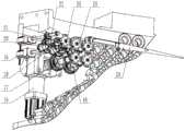
图1为装备总轴测图;Figure 1 is the overall axonometric view of the equipment;
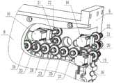
图2为机头部件轴测图;Figure 2 is an axonometric view of the head part;
图3为机头固定组件轴测图;Figure 3 is an axonometric view of the fixed assembly of the machine head;
图4为主传动部件局部视图;Figure 4 is a partial view of the main transmission component;
图5为嵌块驱动单元及侧边嵌块驱动单元局部视图;FIG. 5 is a partial view of the insert drive unit and the side insert drive unit;
图6为机架轴测图;Figure 6 is a frame axonometric view;
图7为收网部件轴测图;Fig. 7 is the axonometric view of the net-receiving part;
图8为封边无结网绞编过程示意图;Fig. 8 is a schematic diagram of a knotless net twisting process of edge sealing;
其中,1-机头部件,2-机架,3-收网部件,4-机头固定组件,5-主传动部件,6-绞编底盘,7-锭子拆卸安装板,8-背板,9-嵌块,10-封边底盘,11-封边背板,12-纱芯管,13-封边纱筒,14-封边纱筒固定架,15-拨盘驱动电机减速器,16-嵌块驱动电机,17-拨盘主动轴组件,18-拨盘过渡轴组件,19-嵌块主动轴组件,20-嵌块从动轴组件,21-侧边嵌块从动轴组件,22-侧边嵌块主动轴组件,23-嵌块过渡轴组件,24-长锭子组件,25-拨盘从动轴组件,26-承力台,27-绞编环安装架,28-主卷网罗拉驱动电机减速器,29-主卷网罗拉,30-主卷网压紧罗拉,31-卷网换向罗拉,32-主卷网联轴器,33-左墙板,34-罗拉轴承座组件,35-右墙板,36-主送网罗拉驱动电机减速器,37-主送网联轴器,38-送网换向罗拉,39-主送网罗拉,40-主送网压紧罗拉。Among them, 1-head part, 2-frame, 3-winding part, 4-head fixing component, 5-main transmission part, 6-twisted chassis, 7-spindle disassembly and installation plate, 8-back plate, 9-Inlay block, 10-Edge sealing chassis, 11-Edge sealing back plate, 12-Yarn core tube, 13-Edge sealing yarn tube, 14-Edge sealing yarn tube holder, 15-Dial drive motor reducer, 16 -Inlay drive motor, 17-Dial drive shaft assembly, 18-Dial transition shaft assembly, 19-Insert drive shaft assembly, 20-Insert driven shaft assembly, 21-Side insert driven shaft assembly, 22-side insert drive shaft assembly, 23-insert transition shaft assembly, 24-long spindle assembly, 25-dial driven shaft assembly, 26-bearing platform, 27-twisted braided ring mounting frame, 28-main Winding net roller drive motor reducer, 29-main winding net roller, 30-main winding net pressing roller, 31-winding net reversing roller, 32-main winding net coupling, 33-left wall plate, 34-roller Bearing seat assembly, 35-right wall plate, 36-main feed net roller drive motor reducer, 37-main feed net coupling, 38- feed net reversing roller, 39-main feed net roller, 40-main feed net Tighten the rollers.
具体实施方式Detailed ways
下面结合具体实施例,进一步阐述本发明。应理解,这些实施例仅用于说明本发明而不用于限制本发明的范围。此外应理解,在阅读了本发明讲授的内容之后,本领域技术人员可以对本发明作各种改动或修改,这些等价形式同样落于本申请所附权利要求书所限定的范围。The present invention will be further described below in conjunction with specific embodiments. It should be understood that these examples are only used to illustrate the present invention and not to limit the scope of the present invention. In addition, it should be understood that after reading the content taught by the present invention, those skilled in the art can make various changes or modifications to the present invention, and these equivalent forms also fall within the scope defined by the appended claims of the present application.
本发明的封边无结网绞编-收网-成型一体化装备,如附图所示,由机头部件1、机架2、收网部件3组成。机架2和收网部件3安装在地基上,两者之间没有机械连接,机头部件1放置在机架2上方。As shown in the accompanying drawings, the edge-sealing non-knotted net twisting-winding-forming integrated equipment of the present invention is composed of a machine head part 1 , a
机头部件1包括机头固定组件4和主传动部件5。The head part 1 includes a head fixing assembly 4 and a main transmission part 5 .
机头固定组件4包括绞编底盘6、锭子拆卸安装板7、背板8、嵌块9、封边底盘10、封边背板11、纱芯管12、封边纱筒13和封边纱筒固定架14。封边底盘10固定在绞编底盘6的上端面,封边底盘10的内侧面与绞编底盘6内侧环面的部分区域共同形成封边区域。n个拨盘设于绞编底盘6除封边区域外的内表面;绞编底盘6除封边区域外的内表面有沿轴向及周向分布的与n个拨盘对应的槽型固定锭子轨道绞,锭子拆卸安装板7固定在n个槽型固定锭子轨道的边缘上。封边区域上加工沿周向排列的2个拨盘及与拨盘对应的槽型固定锭子轨道。该2个拨盘中每个拨盘的中心位置位于封边底盘10和绞编底盘6的交接处。在该两个中心位置处开有通孔,两个纱芯管12分别插入两个通孔。封边背板11固定在封边底盘10的外环面,纱筒固定架14固定在封边背板11外环面,封边纱筒13插入纱筒固定架14的轴上。封边纱筒13上的两根纱线分别穿入两个纱芯管12一直到绞编环。整个编网过程中,自两根纱芯管12引出的两根纱线作为无结网两端的封边,不参与绞编。The head fixing assembly 4 includes a twisted
绞编底盘6外侧环向为凹形腔,背板8固定在外环面上,可将凹形腔封闭。绞编底盘6上的槽型固定锭子轨道交汇处加工与嵌块9直径相等的孔。嵌块9表面加工非交叉锭子轨道,根据工艺要求排布好后,固结在绞编底盘6的孔内形成固定的轨道。The outer circumferential direction of the
主传动部件5包括拨盘驱动电机减速器15、拨盘主动轴组件17、拨盘过渡轴组件18、拨盘从动轴组件25、长锭子组件24、嵌块驱动电机16、嵌块主动轴组件19、侧边嵌块主动轴组件22、嵌块过渡轴组件23、嵌块从动轴组件20和侧边嵌块从动轴组件21。2n个带锥套的长锭子组件24按照1占1空的方式一一对应地排列在n个拨盘的拨盘槽口内。封边区域的2个拨盘仅用于在封边绞编时交换带锥套的长锭子组件24。每个拨盘在固定于绞编底盘6外侧环面上的拨盘驱动机构的驱动下拨动长锭子组件24沿槽型固定锭子轨道及嵌块形成的蛇形锭子路径移动,长锭子组件24的出纱口靠近绞编环。The main transmission component 5 includes the dial
拨盘驱动机构包括安装在背板8的外环面上的两行拨盘驱动电机减速器15,上下两行周向均布,共计16组。每行拨盘驱动电机减速器15的所有拨盘驱动电机减速器15沿周向均布,每个拨盘驱动电机减速器15与一个拨盘主动轴组件17相联结。拨盘主动轴组件17包括套设有拨盘轴承一的拨盘主动轴、拨盘轴向串联齿轮一和拨盘侧边周向齿轮一。拨盘主动轴通过主轴联轴器与拨盘驱动电机减速器15连接,拨盘主动轴带动位置相对应的拨盘转动的同时带动拨盘轴向串联齿轮一和拨盘侧边周向齿轮一同步转动。拨盘过渡轴组件18安装在最上一行和最下一行,与拨盘主动轴组件17相互啮合成2行闭合齿轮传动链。拨盘过渡轴组件包括套设有拨盘轴承二的拨盘过渡轴、拨盘轴向串联齿轮二和拨盘侧边周向齿轮二,共计184个。周向上相邻的拨盘过渡轴组件18的拨盘侧边周向齿轮二与拨盘主动轴组件17的拨盘侧边周向齿轮一相啮合,使得拨盘过渡轴与相邻的拨盘主动轴同步转动,从而带动与拨盘过渡轴位置相应的拨盘及拨盘轴向串联齿轮二转动。周向上相邻的两个拨盘过渡轴组件18的拨盘侧边周向齿轮二相啮合,使得相邻的两个拨盘过渡轴同步转动,从而带动与两个拨盘过渡轴位置相应的拨盘及拨盘轴向串联齿轮二转动.拨盘主动轴组件17及拨盘过渡轴组件18带动与其轴向上相邻的拨盘从动轴组件25转动。拨盘从动轴组件25安装在最上一行和最下一行之间。拨盘从动轴组件25包括套设有拨盘轴承三的拨盘从动轴和拨盘轴向串联齿轮三,共计600个。拨盘从动轴组件25的拨盘轴向串联齿轮三与轴向上相邻的拨盘主动轴组件17的拨盘轴向串联齿轮一或拨盘过渡轴组件的拨盘轴向串联齿轮二相啮合,使得拨盘从动轴与相邻的拨盘主动轴或相邻的拨盘过渡轴同步转动,从而带动与拨盘从动轴位置相应的拨盘及拨盘轴向串联齿轮三转动.轴向上相邻的两个拨盘从动轴组件25的拨盘轴向串联齿轮三相啮合,使得两个相邻的拨盘从动轴同步转动,从而带动与两个拨盘从动轴位置相应的拨盘及拨盘轴向串联齿轮二转动。拨盘主动轴组件17、拨盘过渡轴组件18和拨盘从动轴组件25安装在绞编底盘6加工的径向孔内,可绕该径向孔转动。每列拨盘轴向串联齿轮均相互啮合,组成100列开式齿轮传动链。The dial drive mechanism includes two rows of dial
将在轴向上位于同一竖直线且互相之间没有拨盘的各个嵌块定义为一列嵌块,共有K列嵌块,K为偶数,并将在周向上位于同一水平面且互相之间没有拨盘的各个嵌块定义为一行嵌块,共有J行,每一行有K个嵌块;第2k-1列顶端的嵌块和第2k列底端的每个嵌块由固定于绞编底盘外侧环面上的各自独立的嵌块驱动机构驱动(除去封边区域的一个嵌块),使嵌块在非交叉与交叉状态之间切换,1≤k≤K/2;J行嵌块每行分别由K/4个周向均布的嵌块驱动机构共同控制,行与行之间没有连接关系,每一行上的所有嵌块同步变化;封边区域的位于同一水平面的两个嵌块由单独一个嵌块驱动机构同步控制。即在本发明中,并不是所有嵌块的状态是会发生变化的,某些嵌块是固定在绞编底盘上不动的,其上只加工非交叉锭子轨道,相当于把一部分轨道的形状定好。而会发生状态变化的嵌块都是与下文所论及的嵌块从动轴、侧边嵌块从动轴一体的,其上有交叉锭子轨道和非交叉锭子轨道。Each insert that is located on the same vertical line in the axial direction and has no dials between each other is defined as a row of inserts, there are K rows of inserts, and K is an even number, and they will be on the same horizontal plane in the circumferential direction and there is no mutual between them. Each insert of the dial is defined as a row of inserts, with a total of J rows, and each row has K inserts; Each independent slug drive mechanism on the annular surface drives (except one slug in the edge sealing area) to switch the slug between non-cross and cross states, 1≤k≤K/2; each row of J rows of slugs Controlled by K/4 evenly distributed insert drive mechanisms, there is no connection between rows, and all inserts on each row change synchronously; the two inserts located on the same horizontal plane in the edge sealing area are controlled by a separate one. The insert drive mechanism is controlled synchronously. That is, in the present invention, the state of not all the inserts will change, some inserts are fixed on the twisted chassis, and only the non-crossing spindle rails are processed on them, which is equivalent to changing the shape of a part of the rails. confirm. The slugs that will change state are all integrated with the slug driven shaft and the side slug driven shaft discussed below, and there are crossed spindle tracks and non-crossed spindle tracks on them.
嵌块驱动机构包括安装在背板8外侧环面上的嵌块驱动电机16、安装在绞编底盘6外侧环面上的嵌块主动轴组件19、嵌块过渡轴组件23、嵌块从动轴组件20、侧边嵌块主动轴组件22和侧边嵌块从动轴组件21;每个嵌块驱动电机16与一个嵌块主动轴组件19或侧边嵌块主动轴组件22相联结,将在周向上位于同一轴向位置的一圈各个嵌块定义为一行嵌块,共7行,每行嵌块所在背板8外侧周向均布25个嵌块驱动电机16,每两个相邻嵌块的中心位置安装一个嵌块过渡轴组件23,将四个嵌块从动轴组件20、三个嵌块过渡轴组件23、一个嵌块主动轴组件19和驱动此组件的嵌块驱动电机16定义为一个嵌块驱动单元,则每行嵌块由25个嵌块驱动单元组成,这些单元互相在周向方向上首尾相接,将一个侧边嵌块从动轴组件21、一个侧边嵌块主动轴组件22和驱动此组件的嵌块驱动电机16定义为一个侧边嵌块驱动单元,分布于上下两行相邻拨盘之间,共99个;嵌块主动轴组件19包括套设有嵌块轴承一的嵌块主动轴和嵌块周向齿轮一,嵌块主动轴组件19通过嵌块联轴器与嵌块驱动电机16连接,嵌块主动轴带动嵌块周向齿轮同步转动;嵌块从动轴组件20包括套设有嵌块轴承二的嵌块从动轴和嵌块周向齿轮二,嵌块从动轴组件20安装在嵌块主动轴组件19周向相邻位置,嵌块从动轴组件20的嵌块周向齿轮二与嵌块主动轴组件19的嵌块周向齿轮一啮合,使得嵌块从动轴与相邻的嵌块主动轴同步转动,从而带动与嵌块从动轴位置相应的嵌块转动;嵌块过渡轴组件23包括套设有嵌块轴承三的嵌块过渡轴和嵌块周向齿轮三,嵌块过渡轴组件23安装在嵌块从动轴组件20周向相邻位置,嵌块过渡轴组件23的嵌块周向齿轮三与嵌块从动轴组件20的嵌块周向齿轮二啮合,使得嵌块过渡轴与相邻的嵌块从动轴同步转动;侧边嵌块主动轴组件22包括套设有嵌块轴承四的侧边嵌块主动轴和嵌块轴向齿轮一,侧边嵌块主动轴组件22通过嵌块联轴器与嵌块驱动电机16连接,侧边嵌块主动轴带动嵌块轴向齿轮同步转动;侧边嵌块从动轴组件21包括套设有嵌块轴承五的侧边嵌块从动轴和嵌块轴向齿轮二,侧边嵌块从动轴组件21安装在侧边嵌块主动轴组件22轴向相邻位置,侧边嵌块从动轴组件21的嵌块轴向齿轮二与侧边嵌块主动轴组件22的嵌块轴向齿轮一啮合,使得侧边嵌块从动轴与相邻的侧边嵌块主动轴同步转动,从而带动与侧边嵌块从动轴位置相应的嵌块转动。嵌块主动轴组件19、嵌块过渡轴组件23、嵌块从动轴组件21、侧边嵌块主动轴组件22和侧边嵌块从动轴组件21安装在绞编底盘6加工的径向孔内,可绕该径向孔转动。The slug drive mechanism includes a
主传动的动力传递分为拨盘动力和嵌块动力,拨盘动力顺序有4种,分别为:①拨盘驱动电机减速器15-主轴联轴器-拨盘主动轴组件17-长锭子组件24;②拨盘驱动电机减速器15-主轴联轴器-拨盘主动轴组件17-拨盘过渡轴组件18-长锭子组件24;③拨盘驱动电机减速器15-主轴联轴器-拨盘主动轴组件17-拨盘从动轴组件25-长锭子组件24;④拨盘驱动电机减速器15-主轴联轴器-拨盘主动轴组件17-拨盘过渡轴组件18-拨盘从动轴组件25-长锭子组件24。嵌块动力顺序有3种,分别为:①嵌块驱动电机16-嵌块联轴器-嵌块主动轴组19件-嵌块从动轴组件20;②嵌块驱动电机16-嵌块联轴器-嵌块主动轴组件19-嵌块从动轴组件20-嵌块过渡轴组件23-嵌块从动轴组件20;③嵌块驱动电机16-嵌块联轴器-侧边嵌块主动轴组件22-侧边嵌块从动轴组件21。The power transmission of the main drive is divided into dial power and insert power. There are 4 kinds of dial power sequences, which are: ① dial drive motor reducer 15 - spindle coupling - dial drive shaft assembly 17 -
机架包括承力台26和绞编环安装架27,承力台26安装在地基上,绞编环安装架27固结在承力台26上,机架2上方放置机头部件1,机头轴线与绞编环轴线共线。The frame includes a
收网部件包括左墙板33、右墙板35、罗拉驱动电机减速器(28和36)和若干罗拉(29、30、31、38、39和40);左墙板33和右墙板35安装在地基上,平行布置;主卷网罗拉驱动电机减速器28和主送网罗拉驱动电机减速器36安装在左右墙板外侧,各2个,共计4个;主卷网罗拉29、主卷网压紧罗拉30、卷网换向罗拉31、送网换向罗拉38、主送网罗拉39和主送网压紧罗拉40通过罗拉轴承座组件34安装在墙板之间,主卷网罗拉29两端通过主卷网联轴器32与主卷网罗拉驱动电机减速器28连接,主送网罗拉39两端通过主送网联轴器37与主送网罗拉驱动电机减速器36连接;所有罗拉表面包上橡胶皮,增大与无结网的摩擦力,便于收网。The net take-up part includes left
下面结合具体案例介绍如何采用本发明的封边无结网绞编-收网-成型一体化装备绞编小网目多结节的封边无结网。The following describes how to use the edge-sealing knotless mesh twisting-winding-forming integrated equipment of the present invention to twist a small mesh and multi-node edge-sealing non-knotted mesh with reference to specific cases.
采用本发明绞编400,目脚10mm的封边无结网,绞编底盘6上布置周向100列、轴向8行、封边1行2列,共计802个拨盘,701个嵌块9,176个嵌块主动轴组件19,99个侧边嵌块主动轴组件22,525个嵌块过渡轴组件23,702个嵌块从动轴组件20,99个侧边嵌块从动轴组件21,1600个长锭子组件24,锭子按照“1占1空”排列在拨盘槽口内。为了说明锭子的运动规律,将这些拨盘命名为Ai,i代表拨盘编号顺序,同时定义封边处的2个拨盘为A0和A801,Ai呈蛇形布置;将参与运动的嵌块命名为Bj,j代表嵌块编号顺序,另外封边处的嵌块为B0和B800,Bj呈蛇形布置;定义Bj=1为“编结状态”,表示相邻两拨盘的锭子开始交换,处于绞编结节状态,Bj=0为“编线状态”,表示相邻两拨盘的锭子不交换,处于绞编目脚状态。Using the twisted knitting 400 of the present invention, the mesh foot is 10mm without knotted netting, and the
封边无结网具体绞编步骤如下:The specific twisting steps of edge-sealing and knotless netting are as follows:
(1)所有嵌块驱动电机16停机,Bj=0,处于“编线状态”,编线长度10mm,主卷网电机28以n1转速收网;(1) All the
(2)拨盘驱动电机减速器15和收网部件3同时停机,嵌块驱动电机16旋转90度,使得
(3)所有嵌块驱动电机16停机,拨盘驱动电机减速器15和收网部件3同时开机,Bj处于“编结状态”,A0和A1的锭子交换,A2和A3的锭子交换,……,A800和A801交换;(3) All
(4)拨盘驱动电机减速器15和收网部件3同时停机,嵌块驱动电机16旋转90度,使得
(5)所有嵌块驱动电机16停机,Bj(j=1~799)处于“编线状态”,Bj(j=0,800)处于“编结状态”,A0和A1交换,A800和A801的锭子交换,主卷网电机以n1转速收网;(5) All
(6)拨盘驱动电机减速器15和收网部件3同时停机,旋转嵌块驱动电机16,90度,使得Bj=0;(6) The dial
(7)所有嵌块驱动电16停机,Bj=0,处于“编线状态”,主卷网电机28以n1转速收网;(7) All embedded
(8)拨盘驱动电机减速器15和收网部件3同时停机,嵌块驱动电机16旋转90度,使得
(9)所有嵌块驱动电机16停机,拨盘驱动电机减速器15和收网部件3同时开机,Bj处于“编结状态”,A1和A2的锭子交换,A3和A4的锭子交换,……,A799和A800的锭子交换;(9) All the
(10)拨盘驱动电机减速器15和收网部件3同时停机,旋转嵌块驱动电机16,90度,使得Bj=0;(10) The dial
(11)一直重复步骤(1)至步骤(10),使得纱线在“编线”—“编结”—“编线”间切换状态。(11) Repeat steps (1) to (10) all the time, so that the yarns switch states between "knitting" - "knitting" - "knitting".
Claims (5)
Priority Applications (1)
| Application Number | Priority Date | Filing Date | Title |
|---|---|---|---|
| CN201911135045.9ACN110894641B (en) | 2019-11-19 | 2019-11-19 | Edgebanding and knotless net twisting-winding-forming integrated equipment |
Applications Claiming Priority (1)
| Application Number | Priority Date | Filing Date | Title |
|---|---|---|---|
| CN201911135045.9ACN110894641B (en) | 2019-11-19 | 2019-11-19 | Edgebanding and knotless net twisting-winding-forming integrated equipment |
Publications (2)
| Publication Number | Publication Date |
|---|---|
| CN110894641A CN110894641A (en) | 2020-03-20 |
| CN110894641Btrue CN110894641B (en) | 2020-12-08 |
Family
ID=69787768
Family Applications (1)
| Application Number | Title | Priority Date | Filing Date |
|---|---|---|---|
| CN201911135045.9AExpired - Fee RelatedCN110894641B (en) | 2019-11-19 | 2019-11-19 | Edgebanding and knotless net twisting-winding-forming integrated equipment |
Country Status (1)
| Country | Link |
|---|---|
| CN (1) | CN110894641B (en) |
Families Citing this family (1)
| Publication number | Priority date | Publication date | Assignee | Title |
|---|---|---|---|---|
| CN114855357B (en)* | 2022-05-07 | 2023-06-20 | 南京航空航天大学 | Chassis transmission equipment of rotary three-dimensional braiding machine |
Citations (5)
| Publication number | Priority date | Publication date | Assignee | Title |
|---|---|---|---|---|
| CN106567186A (en)* | 2016-10-08 | 2017-04-19 | 东华大学 | Inner ring horizontal three-dimensional braiding machine and its robot mandrel traction system |
| CN106592096A (en)* | 2017-01-24 | 2017-04-26 | 青岛中亿伟业机械制造有限公司 | Rotary oft pipe knitting machine |
| CN106884262A (en)* | 2017-04-24 | 2017-06-23 | 东华大学 | A kind of control of two-dimensional braided machine method for designing for weaving odd-shaped cross section preformed member |
| CN206477109U (en)* | 2017-01-24 | 2017-09-08 | 青岛中亿伟业机械制造有限公司 | A kind of swinging flexible pipe braider |
| CN110016761A (en)* | 2019-04-28 | 2019-07-16 | 徐州恒辉编织机械有限公司 | A knitting platform of a round and flat surgical suture knitting machine |
Family Cites Families (1)
| Publication number | Priority date | Publication date | Assignee | Title |
|---|---|---|---|---|
| CN106192198B (en)* | 2011-10-17 | 2020-06-05 | 后续医疗股份有限公司 | Knitting mechanism |
- 2019
- 2019-11-19CNCN201911135045.9Apatent/CN110894641B/ennot_activeExpired - Fee Related
Patent Citations (5)
| Publication number | Priority date | Publication date | Assignee | Title |
|---|---|---|---|---|
| CN106567186A (en)* | 2016-10-08 | 2017-04-19 | 东华大学 | Inner ring horizontal three-dimensional braiding machine and its robot mandrel traction system |
| CN106592096A (en)* | 2017-01-24 | 2017-04-26 | 青岛中亿伟业机械制造有限公司 | Rotary oft pipe knitting machine |
| CN206477109U (en)* | 2017-01-24 | 2017-09-08 | 青岛中亿伟业机械制造有限公司 | A kind of swinging flexible pipe braider |
| CN106884262A (en)* | 2017-04-24 | 2017-06-23 | 东华大学 | A kind of control of two-dimensional braided machine method for designing for weaving odd-shaped cross section preformed member |
| CN110016761A (en)* | 2019-04-28 | 2019-07-16 | 徐州恒辉编织机械有限公司 | A knitting platform of a round and flat surgical suture knitting machine |
Also Published As
| Publication number | Publication date |
|---|---|
| CN110894641A (en) | 2020-03-20 |
Similar Documents
| Publication | Publication Date | Title |
|---|---|---|
| JPS5936017B2 (en) | Thick fabric body manufacturing equipment | |
| CN110184737B (en) | Closed Knotless Weaving Line | |
| CN110894641B (en) | Edgebanding and knotless net twisting-winding-forming integrated equipment | |
| CN110791875B (en) | Closed knotless net twisting-winding-forming integrated equipment | |
| CN110042561B (en) | Multicolor national clothing decoration belt braiding machine | |
| CN104091653B (en) | Roll-in bunch frame winch | |
| CN102277660B (en) | One-step double-twisting machine | |
| CN112442766B (en) | Double-yarn-feeding twisting type storage yarn feeder and application thereof | |
| CN103290584A (en) | A covered wire machine | |
| CN110983614B (en) | Closed knotless net weaving-winding-forming integrated equipment | |
| CN111020865B (en) | Knotless mesh weaving-winding-forming integrated equipment for edge banding | |
| CN110016760B (en) | Weaving method of variable mesh and knotless net | |
| CN111270408A (en) | Weaving machine's of national clothing modification area formula shift fork system of drawing | |
| CN104480600A (en) | Yarn coating machine with improved structure | |
| CN100360256C (en) | Metal silk-screen braider | |
| CN104562354B (en) | A kind of silk covering machine of tape handler | |
| CN110318157B (en) | Knotless net weaving production line | |
| CN212404429U (en) | Weaving machine's of national clothing modification area formula shift fork system of drawing | |
| CN116676696A (en) | Twisting and cladding integrated machine for multiple yarns | |
| CN212404428U (en) | Weaving machine for decorative belt of trace style national clothes | |
| CN204058756U (en) | The yarn guide of adjusting yarn tension | |
| CN209024733U (en) | A three-dimensional structure stitch-bonding forming equipment | |
| CN211311774U (en) | Vertical multi-warp-knitting machine | |
| CN208533002U (en) | The transmission mechanism of chenille yarn machine | |
| CN110923941B (en) | Equipment and method for knotless net twisting of edge banding |
Legal Events
| Date | Code | Title | Description |
|---|---|---|---|
| PB01 | Publication | ||
| PB01 | Publication | ||
| SE01 | Entry into force of request for substantive examination | ||
| SE01 | Entry into force of request for substantive examination | ||
| GR01 | Patent grant | ||
| GR01 | Patent grant | ||
| CF01 | Termination of patent right due to non-payment of annual fee | ||
| CF01 | Termination of patent right due to non-payment of annual fee | Granted publication date:20201208 |