CN110893969B - A freight picks up floor truck for intelligent warehouse - Google Patents
A freight picks up floor truck for intelligent warehouseDownload PDFInfo
- Publication number
- CN110893969B CN110893969BCN201911329940.4ACN201911329940ACN110893969BCN 110893969 BCN110893969 BCN 110893969BCN 201911329940 ACN201911329940 ACN 201911329940ACN 110893969 BCN110893969 BCN 110893969B
- Authority
- CN
- China
- Prior art keywords
- cavity
- sliding
- fixedly connected
- face
- auxiliary
- Prior art date
- Legal status (The legal status is an assumption and is not a legal conclusion. Google has not performed a legal analysis and makes no representation as to the accuracy of the status listed.)
- Active
Links
Images


Classifications
- B—PERFORMING OPERATIONS; TRANSPORTING
- B65—CONVEYING; PACKING; STORING; HANDLING THIN OR FILAMENTARY MATERIAL
- B65G—TRANSPORT OR STORAGE DEVICES, e.g. CONVEYORS FOR LOADING OR TIPPING, SHOP CONVEYOR SYSTEMS OR PNEUMATIC TUBE CONVEYORS
- B65G1/00—Storing articles, individually or in orderly arrangement, in warehouses or magazines
- B65G1/02—Storage devices
- B65G1/04—Storage devices mechanical
- B65G1/0492—Storage devices mechanical with cars adapted to travel in storage aisles
- B—PERFORMING OPERATIONS; TRANSPORTING
- B65—CONVEYING; PACKING; STORING; HANDLING THIN OR FILAMENTARY MATERIAL
- B65G—TRANSPORT OR STORAGE DEVICES, e.g. CONVEYORS FOR LOADING OR TIPPING, SHOP CONVEYOR SYSTEMS OR PNEUMATIC TUBE CONVEYORS
- B65G47/00—Article or material-handling devices associated with conveyors; Methods employing such devices
- B65G47/74—Feeding, transfer, or discharging devices of particular kinds or types
- B65G47/90—Devices for picking-up and depositing articles or materials
- B—PERFORMING OPERATIONS; TRANSPORTING
- B65—CONVEYING; PACKING; STORING; HANDLING THIN OR FILAMENTARY MATERIAL
- B65G—TRANSPORT OR STORAGE DEVICES, e.g. CONVEYORS FOR LOADING OR TIPPING, SHOP CONVEYOR SYSTEMS OR PNEUMATIC TUBE CONVEYORS
- B65G2201/00—Indexing codes relating to handling devices, e.g. conveyors, characterised by the type of product or load being conveyed or handled
- B65G2201/02—Articles
- B65G2201/0285—Postal items, e.g. letters, parcels
Landscapes
- Engineering & Computer Science (AREA)
- Mechanical Engineering (AREA)
- Warehouses Or Storage Devices (AREA)
Abstract
Translated fromChinese
Description
Translated fromChinese技术领域technical field
本发明涉及仓储运输技术领域,具体为一种用于智能仓库的货物拾取搬运小车。The invention relates to the technical field of warehousing and transportation, in particular to a trolley for picking up and transporting goods for an intelligent warehouse.
背景技术Background technique
物流运输中重要一环为仓储技术,目前的物流行业的智能仓库系统中使用自动导引运输车(AGV),进行较小包裹的运输,但由于目前的自动导引运输车不具有拾取包裹的功能,使得自动导引运输车需要其他设备将包裹搬运到运输车上,且无法直接将需要储存的包裹储存在货架上,由于自动导引运输车基本没有包裹夹持功能,使得搬运过程中存在包裹掉落问题,又由于自动导引运输车没有拾取功能,使得包裹掉落无法进行拾取,从而影响整个智能仓库正常运作,本发明阐明的一种能解决上述问题的设备。An important part of logistics transportation is warehousing technology. The current intelligent warehouse system in the logistics industry uses automatic guided vehicles (AGVs) to transport smaller packages, but because the current automatic guided vehicles do not have the ability to pick up packages. function, so that the automatic guided transport vehicle needs other equipment to transport the package to the transport vehicle, and the package that needs to be stored cannot be directly stored on the shelf. The problem of package falling, and because the automatic guided transport vehicle has no pickup function, the package cannot be picked up after falling, thus affecting the normal operation of the entire intelligent warehouse. The present invention illustrates a device that can solve the above problem.
发明内容SUMMARY OF THE INVENTION
技术问题:目前的AGV不具有拾取包裹和夹持包裹功能,会发生包裹掉落,从而影响整个智能仓库正常运作。Technical problem: The current AGV does not have the function of picking up the package and holding the package, and the package will fall, which will affect the normal operation of the entire smart warehouse.
为解决上述问题,本例设计了一种用于智能仓库的货物拾取搬运小车,本例的一种用于智能仓库的货物拾取搬运小车,包括车体底板,所述车体底板上设有左右对称的伸缩车体装置,所述伸缩车体装置能根据包裹大小进行伸缩从而适应不同大小的包裹,所述伸缩车体装置包括两个滑动连接于所述车体底板前侧端面上的滑动车体装置,且两个所述滑动车体装置左右对称,所述滑动车体装置靠近对称中心一侧端面上固定连接有限位板,所述滑动车体装置前侧端面上固定连接有固定块,所述固定块远离对称中心一侧端面上固定连接有固定杆,所述车体底板前侧端面上固定连接有伸缩气缸,所述车体底板上设有位于伸缩车体装置上侧的升降输送装置,所述升降输送装置能带动包裹升降并将包裹输送到货架上,每个所述固定杆上设有用于拾取包裹的包裹拾取装置,且两个所述包裹拾取装置左右对称,所述包裹拾取装置包括固定连接于所述固定杆远离所述滑动车体装置一侧端面上的气缸,所述气缸内设有气腔,所述气腔内滑动连接有活塞,所述活塞与所述气腔靠近所述滑动车体装置一侧内壁之间连接有压缩弹簧,所述气腔下侧端面上设有排气电磁阀,所述活塞靠近对称中心一侧端面上固定连接有夹持杆,所述夹持杆延伸至所述固定杆靠近所述滑动车体装置一侧端面外,所述夹持杆上固定连接有位于所述固定杆靠近所述滑动车体装置一侧的夹持板,所述夹持板内设有开口朝向远离所述固定杆一侧的夹持腔,所述包裹拾取装置上设有用于检测是否夹持稳定的夹持检测装置。In order to solve the above problems, a cargo picking and handling trolley for smart warehouses is designed in this example. The cargo picking and handling trolley for smart warehouses in this example includes a vehicle body bottom plate, and the left and right sides are provided on the vehicle body bottom plate. Symmetrical telescopic vehicle body device, which can be expanded and retracted according to the size of the package to adapt to different sizes of packages, the telescopic vehicle body device includes two sliding carts slidably connected to the front side end surface of the vehicle body floor and the two sliding car body devices are left and right symmetrical, the end surface of the sliding car body device is fixedly connected to a limit plate on one end surface close to the symmetrical center, and the front end surface of the sliding car body device is fixedly connected with a fixing block, A fixing rod is fixedly connected to the end surface of the fixing block on one side away from the symmetrical center, a telescopic cylinder is fixedly connected to the end surface of the front side of the vehicle body bottom plate, and a lifting conveyor located on the upper side of the telescopic vehicle body device is arranged on the vehicle body bottom plate. The lifting and conveying device can drive the package to lift up and down and transport the package to the shelf. Each fixed rod is provided with a package pickup device for picking up the package, and the two package pickup devices are symmetrical on both sides. The pickup device includes a cylinder fixedly connected to the end face of the fixing rod away from the sliding vehicle body device, an air cavity is arranged in the air cylinder, a piston is slidably connected in the air cavity, and the piston is connected to the air cavity. A compression spring is connected between the inner wall of one side of the cavity close to the sliding car body device, an exhaust solenoid valve is arranged on the end surface of the lower side of the air cavity, and a clamping rod is fixedly connected to the end surface of one side of the piston close to the symmetrical center. The clamping rod extends to the outside of the end face of the fixing rod on the side close to the sliding vehicle body device, and a clamping plate located on the side of the fixing rod close to the sliding vehicle body device is fixedly connected to the clamping rod , the clamping plate is provided with a clamping cavity with an opening facing the side away from the fixing rod, and a clamping detection device for detecting whether the clamping is stable is provided on the package pickup device.
可优选地,所述伸缩气缸内设有活塞腔,所述活塞腔上侧端面上设有电磁阀,所述活塞腔内滑动连接有左右对称的两个副活塞,且所述电磁阀位于两个所述副活塞之间,所述副活塞与所述活塞腔远离所述电磁阀一侧内壁之间连接有弹簧,所述副活塞远离所述电磁阀一侧端面上固定连接有活塞杆,所述活塞杆向远离所述电磁阀一侧延伸至所述活塞腔端面外,所述活塞杆与所述滑动车体装置固定连接,所述滑动车体装置下侧端面上固定连接有楔形台,所述滑动车体装置内设有开口朝前的滑孔,且所述滑孔位于所述固定块靠近所述伸缩气缸一侧处,所述滑孔内滑动连接有可向前延伸至所述滑动车体装置上侧端面外的斜面限位销,所述斜面限位销与所述滑孔后侧内壁之间连接有副弹簧,所述滑动车体装置内转动连接有两根向远离所述伸缩气缸一侧延伸至所述滑动车体装置端面外的车轮轴,且所述滑动车体装置能带动所述车轮轴转动,所述车轮轴上固定连接有车轮,左侧的所述固定杆左侧端面上固定连接有气泵,所述气泵左侧端面上设有三通电磁阀,所述三通电磁阀与所述活塞腔之间相通连接有输气管。Preferably, a piston cavity is provided in the telescopic cylinder, a solenoid valve is provided on the upper end surface of the piston cavity, two auxiliary pistons with left and right symmetry are slidably connected in the piston cavity, and the solenoid valve is located on the two sides. Between each of the auxiliary pistons, a spring is connected between the auxiliary piston and the inner wall of the piston cavity on the side away from the solenoid valve, and a piston rod is fixedly connected on the end surface of the auxiliary piston away from the solenoid valve. The piston rod extends to the side away from the solenoid valve to the outside of the end surface of the piston cavity, the piston rod is fixedly connected with the sliding vehicle body device, and a wedge-shaped platform is fixedly connected on the end surface of the lower side of the sliding vehicle body device , the sliding body device is provided with a sliding hole with an opening facing forward, and the sliding hole is located at the side of the fixing block close to the telescopic cylinder, and the sliding hole is slidably connected with a sliding hole that can extend forward to any The inclined surface limit pin outside the upper end face of the sliding car body device, a secondary spring is connected between the inclined surface limit pin and the inner wall of the rear side of the sliding hole, and the sliding car body device is rotatably connected with two moving away from One side of the telescopic cylinder extends to the wheel shaft outside the end face of the sliding body device, and the sliding body device can drive the wheel shaft to rotate, the wheel shaft is fixedly connected with a wheel, and the left An air pump is fixedly connected on the left end surface of the fixing rod, a three-way solenoid valve is arranged on the left end surface of the air pump, and an air delivery pipe is communicated with the piston cavity.
可优选地,所述升降输送装置包括固定连接于所述车体底板前侧端面上的压缩升降装置,所述压缩升降装置位于两个所述滑动车体装置之间,所述压缩升降装置内设有向前延伸至所述压缩升降装置端面外的伸缩杆,所述伸缩杆前侧设有位于所述限位板上侧的升降平台,且所述升降平台可与所述限位板抵接,所述升降平台内设有升降腔,所述升降腔后侧端面与所述伸缩杆固定连接,所述升降腔前侧内壁上滑动连接有向远离所述伸缩杆一侧延伸至所述升降腔端面外的滑杆,所述滑杆内设有开口朝后的限位孔,所述斜面限位销可延伸至所述限位孔内,从而限制所述滑杆移动,所述滑杆前侧端面上固定连接有输送板,所述输送板靠近所述升降平台一侧端面与所述升降平台之间连接有副拉伸弹簧,所述输送板内设有开口朝向所述压缩升降装置一侧的输送腔,所述输送腔后侧内壁上转动连接有向前延伸的副带轮轴,所述副带轮轴上固定连接有副输送带轮,同一侧的两个所述副输送带轮之间连接有副输送带,上侧的所述副带轮轴上动力连接有固定连接于所述输送腔后侧内壁上的副输送电机,右侧的所述输送板前侧端面上固定连接有视觉模块。Preferably, the lifting and conveying device includes a compression lifting device fixedly connected to the front end surface of the vehicle body floor, the compression lifting device is located between the two sliding vehicle body devices, and the compression lifting device is inside the compression lifting device. There is a telescopic rod extending forward to the outside of the end face of the compression lifting device, and a lifting platform located on the upper side of the limit plate is arranged on the front side of the telescopic rod, and the lifting platform can abut against the limit plate The lifting platform is provided with a lifting cavity, the rear end face of the lifting cavity is fixedly connected with the telescopic rod, and the inner wall of the front side of the lifting cavity is slidably connected with a side extending away from the telescopic rod to the The sliding rod outside the end face of the lifting cavity is provided with a limit hole with a rearward opening, and the inclined plane limit pin can extend into the limit hole, thereby restricting the movement of the sliding rod, the sliding A conveying plate is fixedly connected to the end surface of the front side of the rod. A secondary tension spring is connected between the end surface of the conveying plate near the side of the lifting platform and the lifting platform. The conveying plate is provided with an opening facing the compression lift. The conveying cavity on one side of the device, the inner wall of the rear side of the conveying cavity is rotatably connected with the auxiliary pulley shaft extending forward, the auxiliary conveying pulley is fixedly connected to the auxiliary pulley shaft, and the two auxiliary conveying belts on the same side are connected with each other. The auxiliary conveyor belt is connected between the wheels, the auxiliary conveying motor fixedly connected to the inner wall of the rear side of the conveying cavity is connected to the power of the auxiliary pulley shaft on the upper side, and the front end surface of the conveying plate on the right side is fixedly connected with the auxiliary conveying motor. Vision module.
可优选地,所述夹持腔后侧内壁上转动连接有两根上下对称且向前延伸的带轮轴,所述带轮轴上固定连接有输送带轮,前侧的所述带轮轴上动力连接有固定连接于所述夹持腔后侧内壁上的输送电机,同一侧的两个所述输送带轮之间连接有输送带,所述气缸上侧端面上固定连接有阀体,所述阀体内设有阀体腔,左侧的所述气腔与所述阀体腔之间相通连接有连管,左侧的所述阀体腔与所述三通电磁阀之间相通连接有进气管,所述进气管与右侧的所述阀体腔之间相通连接有连接管。Preferably, two pulley shafts that are symmetrical up and down and extend forward are rotatably connected to the inner wall of the rear side of the clamping cavity. There is a conveying motor fixedly connected to the inner wall of the rear side of the clamping cavity, a conveying belt is connected between the two conveying pulleys on the same side, a valve body is fixedly connected to the upper end surface of the cylinder, and the valve There is a valve body cavity in the body, a connecting pipe is communicated between the air cavity on the left side and the valve body cavity, and an air intake pipe is communicated between the valve body cavity on the left side and the three-way solenoid valve. A connecting pipe is communicated and connected between the intake pipe and the valve body cavity on the right side.
可优选地,所述夹持检测装置包括转动连接于所述夹持板前侧端面上且前后延伸的转轮轴,所述转轮轴延伸至所述夹持板后侧端面外,所述转轮轴位于所述夹持腔上侧,所述转轮轴上固定连接有位于所述夹持板前侧的转轮,所述转轮轴上固定连接有位于所述夹持板后侧的转盘,所述转盘内设有副气腔,所述副气腔左侧内壁上设有左右贯通的排气孔,所述副气腔内滑动连接有滑塞,所述滑塞与所述副气腔右侧内壁之间连接有拉伸弹簧,所述转盘下侧端面上与所述阀体腔之间相通连接有气路软管,且所述气路软管与所述副气腔下侧端面转动连接,所述阀体腔内滑动连接有可关闭所述阀体腔的阀芯,所述阀芯与所述阀体腔下侧内壁之间连接有复位弹簧,所述阀体腔后侧内壁上转动连接有齿轮,所述气路软管内滑动连接有副滑塞,所述副滑塞下侧端面和所述阀芯上侧端面上均固定连接有齿条,所述齿条与所述齿轮啮合连接。Preferably, the clamping detection device includes a runner shaft that is rotatably connected to the front end face of the clamping plate and extends forward and backward, the runner shaft extends to the outside of the rear end face of the clamping plate, and the runner shaft is located at the rear end surface of the clamping plate. On the upper side of the clamping cavity, the rotating wheel located on the front side of the clamping plate is fixedly connected to the rotating wheel shaft, and the rotating disk located on the rear side of the clamping plate is fixedly connected to the rotating wheel shaft. A secondary air cavity is provided, the left inner wall of the auxiliary air cavity is provided with a left and right through exhaust hole, a sliding plug is slidably connected in the auxiliary air cavity, and the sliding plug is connected to the right inner wall of the auxiliary air cavity. A tension spring is connected between the two sides, an air hose is connected between the lower end surface of the turntable and the valve body cavity, and the air hose is rotatably connected to the lower end surface of the auxiliary air chamber. A valve core that can close the valve body cavity is slidably connected in the valve body cavity, a return spring is connected between the valve core and the inner wall of the lower side of the valve body cavity, and a gear is rotatably connected to the inner wall of the rear side of the valve body cavity. A secondary slide plug is slidably connected in the air path hose, and a rack is fixedly connected to the lower end surface of the secondary slide plug and the upper end surface of the valve core, and the gear rack is engaged with the gear.
本发明的有益效果是:本发明的包裹拾取机构能根据包裹大小改变车体宽度,从而能拾取运输大小不同的包裹,且拾取机构上的夹持可靠性检测机构能检测包裹是否夹持稳定,从而提高包裹拾取的可靠性和避免过大夹持力损伤包裹,升降输送机构上的夹持机构能对包裹进行夹持固定,从而避免运输过程中包裹掉落,升降输送机构能将包裹输送到相应的货架上存放,因此本发明能自动拾取包裹和将包裹储存到相应货架上,从而能提高智能仓库运作的稳定性。The beneficial effects of the present invention are: the package pickup mechanism of the present invention can change the width of the vehicle body according to the size of the package, so as to pick up packages of different transport sizes, and the clamping reliability detection mechanism on the pickup mechanism can detect whether the package is clamped stably, In order to improve the reliability of package picking and avoid damage to the package by excessive clamping force, the clamping mechanism on the lifting and conveying mechanism can clamp and fix the package, so as to prevent the package from falling during transportation, and the lifting and conveying mechanism can transport the package to Therefore, the present invention can automatically pick up the packages and store them on the corresponding shelves, thereby improving the stability of the intelligent warehouse operation.
附图说明Description of drawings
为了易于说明,本发明由下述的具体实施例及附图作以详细描述。For ease of description, the present invention is described in detail by the following specific embodiments and accompanying drawings.
图1为本发明的一种用于智能仓库的货物拾取搬运小车的整体结构示意图;1 is a schematic diagram of the overall structure of a cargo pickup and handling trolley for an intelligent warehouse according to the present invention;
图2为图1的“A-A”方向的结构示意图;Fig. 2 is the structural representation of the "A-A" direction of Fig. 1;
图3为图1的“B-B”方向的结构示意图;Fig. 3 is the structural representation of the "B-B" direction of Fig. 1;
图4为图3的“C-C”方向的结构示意图;Fig. 4 is the structural representation of the "C-C" direction of Fig. 3;
图5为图1的“D-D”方向的结构示意图;Fig. 5 is the structural representation of " D-D " direction of Fig. 1;
图6为图1的“E-E”方向的结构示意图;Fig. 6 is the structural representation of the "E-E" direction of Fig. 1;
图7为图1的“F”处的结构放大示意图;Fig. 7 is a schematic enlarged view of the structure at "F" of Fig. 1;
图8为图1的“G”处的结构放大示意图;Fig. 8 is a schematic enlarged view of the structure at "G" of Fig. 1;
图9为图3的“H”处的结构放大示意图。FIG. 9 is an enlarged schematic view of the structure at “H” of FIG. 3 .
具体实施方式Detailed ways
下面结合图1至图9对本发明进行详细说明,为叙述方便,现对下文所说的方位规定如下:下文所说的上下左右前后方向与图1本身投影关系的上下左右前后方向一致。The present invention will be described in detail below in conjunction with Fig. 1 to Fig. 9. For the convenience of description, the orientations mentioned below are now specified as follows: the up, down, left, right, front, and rear directions mentioned below are consistent with the up, down, left, right, front, and rear directions of the projection relationship of Fig. 1 itself.
本发明涉及一种用于智能仓库的货物拾取搬运小车,主要应用于仓储运输,下面将结合本发明附图对本发明做进一步说明:The present invention relates to a kind of goods picking and handling trolley for intelligent warehouse, which is mainly applied to warehousing and transportation. The present invention will be further described below with reference to the accompanying drawings of the present invention:
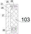
本发明所述的一种用于智能仓库的货物拾取搬运小车,包括车体底板11,所述车体底板11上设有左右对称的伸缩车体装置101,所述伸缩车体装置101能根据包裹大小进行伸缩从而适应不同大小的包裹,所述伸缩车体装置101包括两个滑动连接于所述车体底板11前侧端面上的滑动车体装置14,且两个所述滑动车体装置14左右对称,所述滑动车体装置14靠近对称中心一侧端面上固定连接有限位板48,所述滑动车体装置14前侧端面上固定连接有固定块20,所述固定块20远离对称中心一侧端面上固定连接有固定杆24,所述车体底板11前侧端面上固定连接有伸缩气缸18,所述车体底板11上设有位于伸缩车体装置101上侧的升降输送装置102,所述升降输送装置102能带动包裹升降并将包裹输送到货架上,每个所述固定杆24上设有用于拾取包裹的包裹拾取装置103,且两个所述包裹拾取装置103左右对称,所述包裹拾取装置103包括固定连接于所述固定杆24远离所述滑动车体装置14一侧端面上的气缸31,所述气缸31内设有气腔32,所述气腔32内滑动连接有活塞34,所述活塞34与所述气腔32靠近所述滑动车体装置14一侧内壁之间连接有压缩弹簧33,所述气腔32下侧端面上设有排气电磁阀61,所述活塞34靠近对称中心一侧端面上固定连接有夹持杆30,所述夹持杆30延伸至所述固定杆24靠近所述滑动车体装置14一侧端面外,所述夹持杆30上固定连接有位于所述固定杆24靠近所述滑动车体装置14一侧的夹持板21,所述夹持板21内设有开口朝向远离所述固定杆24一侧的夹持腔26,所述包裹拾取装置103上设有用于检测是否夹持稳定的夹持检测装置104。A cargo picking and handling trolley for an intelligent warehouse according to the present invention includes a vehicle
有益地,所述伸缩气缸18内设有活塞腔68,所述活塞腔68上侧端面上设有电磁阀67,所述活塞腔68内滑动连接有左右对称的两个副活塞70,且所述电磁阀67位于两个所述副活塞70之间,所述副活塞70与所述活塞腔68远离所述电磁阀67一侧内壁之间连接有弹簧69,所述副活塞70远离所述电磁阀67一侧端面上固定连接有活塞杆19,所述活塞杆19向远离所述电磁阀67一侧延伸至所述活塞腔68端面外,所述活塞杆19与所述滑动车体装置14固定连接,所述滑动车体装置14下侧端面上固定连接有楔形台59,所述滑动车体装置14内设有开口朝前的滑孔74,且所述滑孔74位于所述固定块20靠近所述伸缩气缸18一侧处,所述滑孔74内滑动连接有可向前延伸至所述滑动车体装置14上侧端面外的斜面限位销17,所述斜面限位销17与所述滑孔74后侧内壁之间连接有副弹簧73,所述滑动车体装置14内转动连接有两根向远离所述伸缩气缸18一侧延伸至所述滑动车体装置14端面外的车轮轴15,且所述滑动车体装置14能带动所述车轮轴15转动,所述车轮轴15上固定连接有车轮16,左侧的所述固定杆24左侧端面上固定连接有气泵39,所述气泵39左侧端面上设有三通电磁阀40,所述三通电磁阀40与所述活塞腔68之间相通连接有输气管41,通过所述气泵39生产气流,气流通过所述三通电磁阀40、所述输气管41输送到所述活塞腔68内,并推动所述副活塞70向远离所述电磁阀67一侧移动,从而带动所述滑动车体装置14向远离所述伸缩气缸18一侧移动,实现适应较大的包裹。Beneficially, the
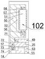
有益地,所述升降输送装置102包括固定连接于所述车体底板11前侧端面上的压缩升降装置13,所述压缩升降装置13位于两个所述滑动车体装置14之间,所述压缩升降装置13内设有向前延伸至所述压缩升降装置13端面外的伸缩杆12,所述伸缩杆12前侧设有位于所述限位板48上侧的升降平台49,且所述升降平台49可与所述限位板48抵接,所述升降平台49内设有升降腔53,所述升降腔53后侧端面与所述伸缩杆12固定连接,所述升降腔53前侧内壁上滑动连接有向远离所述伸缩杆12一侧延伸至所述升降腔53端面外的滑杆25,所述滑杆25内设有开口朝后的限位孔72,所述斜面限位销17可延伸至所述限位孔72内,从而限制所述滑杆25移动,所述滑杆25前侧端面上固定连接有输送板50,所述输送板50靠近所述升降平台49一侧端面与所述升降平台49之间连接有副拉伸弹簧71,所述输送板50内设有开口朝向所述压缩升降装置13一侧的输送腔52,所述输送腔52后侧内壁上转动连接有向前延伸的副带轮轴58,所述副带轮轴58上固定连接有副输送带轮51,同一侧的两个所述副输送带轮51之间连接有副输送带57,上侧的所述副带轮轴58上动力连接有固定连接于所述输送腔52后侧内壁上的副输送电机56,右侧的所述输送板50前侧端面上固定连接有视觉模块75,通过所述压缩升降装置13带动所述伸缩杆12向上移动,能带动所述升降平台49向上移动,从而实现提升包裹。Beneficially, the lifting and conveying
有益地,所述夹持腔26后侧内壁上转动连接有两根上下对称且向前延伸的带轮轴28,所述带轮轴28上固定连接有输送带轮29,前侧的所述带轮轴28上动力连接有固定连接于所述夹持腔26后侧内壁上的输送电机60,同一侧的两个所述输送带轮29之间连接有输送带27,所述气缸31上侧端面上固定连接有阀体36,所述阀体36内设有阀体腔63,左侧的所述气腔32与所述阀体腔63之间相通连接有连管35,左侧的所述阀体腔63与所述三通电磁阀40之间相通连接有进气管38,所述进气管38与右侧的所述阀体腔63之间相通连接有连接管42,通过所述夹持板21向靠近所述压缩升降装置13一侧移动能实现夹持包裹。Beneficially, two
有益地,所述夹持检测装置104包括转动连接于所述夹持板21前侧端面上且前后延伸的转轮轴22,所述转轮轴22延伸至所述夹持板21后侧端面外,所述转轮轴22位于所述夹持腔26上侧,所述转轮轴22上固定连接有位于所述夹持板21前侧的转轮23,所述转轮轴22上固定连接有位于所述夹持板21后侧的转盘43,所述转盘43内设有副气腔47,所述副气腔47左侧内壁上设有左右贯通的排气孔45,所述副气腔47内滑动连接有滑塞46,所述滑塞46与所述副气腔47右侧内壁之间连接有拉伸弹簧44,所述转盘43下侧端面上与所述阀体腔63之间相通连接有气路软管37,且所述气路软管37与所述副气腔47下侧端面转动连接,所述阀体腔63内滑动连接有可关闭所述阀体腔63的阀芯64,所述阀芯64与所述阀体腔63下侧内壁之间连接有复位弹簧62,所述阀体腔63后侧内壁上转动连接有齿轮78,所述气路软管37内滑动连接有副滑塞66,所述副滑塞66下侧端面和所述阀芯64上侧端面上均固定连接有齿条65,所述齿条65与所述齿轮78啮合连接,当所述输送带27完成可靠的夹持包裹时,则能使所述输送带27带动包裹移动的速度达到设定值,由于包裹移动能带动所述转轮23转动,使得所述滑塞46在离心力作用下,向远离所述转轮轴22一侧移动,则可带动所述阀芯64下移关闭所述阀体腔63,从而使所述活塞34停止移动,从而能夹持的稳定性和可靠性。Beneficially, the clamping
以下结合图1至图9对本文中的一种用于智能仓库的货物拾取搬运小车的使用步骤进行详细说明:The following describes in detail the steps of using a cargo picking and handling trolley for a smart warehouse in this article with reference to FIGS. 1 to 9 :
开始时,输送板50位于后限位处,输送板50位于靠近压缩升降装置13一侧限位处,斜面限位销17位于限位孔72内,从而使滑动车体装置14能得到滑杆25移动,在弹簧69作用下,副活塞70位于靠近电磁阀67一侧限位处,电磁阀67处于关闭状态,使得滑动车体装置14位于靠近压缩升降装置13一侧限位处,输送板50位于靠近升降平台49一侧限位处,在压缩弹簧33作用下,活塞34位于远离夹持板21一侧限位处,排气电磁阀61处于关闭状态,在复位弹簧62作用下,阀芯64位于上限位处,副滑塞66位于下限位处。At the beginning, the conveying
工作时,滑动车体装置14带动车轮轴15和车轮16转动,实现车体底板11移动,视觉模块75寻找发现需要搬运的包裹,During operation, the sliding
当包裹较大时,气泵39启动,三通电磁阀40使气泵39与输气管41相通,气泵39与进气管38不相通,气泵39产生的气流通过输气管41输送到活塞腔68内带动副活塞70向远离电磁阀67一侧移动到合适位置,When the package is large, the
当个包裹较小时,且副活塞70未在靠近电磁阀67一侧限位处时,电磁阀67开启,在弹簧69作用下,副活塞70向靠近电磁阀67一侧移动,副活塞70通过活塞杆19带动滑动车体装置14移动,痛过控制电磁阀67开启时间能控制滑动车体装置14移动距离,因此能实现自动适应包裹大小,When the package is small and the
之后三通电磁阀40使气泵39与进气管38相通,输送电机60启动,气泵39内的气流通过进气管38、连接管42、阀体腔63、连管35输送到气腔32内,并推动活塞34向靠近伸缩气缸18一侧移动,实现对包裹的夹持,输送电机60带动下侧的带轮轴28和输送带轮29转动,从而带动输送带27转动,输送带27带动包裹向上移动,包裹上移带动转轮23转动,当输送带27实现对包裹的可靠夹持后,转轮23带动转轮轴22转动,转轮轴22带动转盘43和滑塞46转动,滑塞46在离心力作用下,移动到远离转轮轴22一侧限位处,滑塞46移动产生的负压输送到气路软管37内,使副滑塞66向上移动,副滑塞66上的齿条65通过啮合连接带动齿轮78转动,齿轮78通过啮合连接带动阀芯64和阀芯64上的齿条65向下移动,从而关闭阀体腔63,实现可靠的夹持包裹,之后气泵39停转,After that, the three-way solenoid valve 40 makes the
之后输送带27带动包裹向上移动到升降平台49前侧端面上,之后输送电机60停转,使得转轮23停转,在拉伸弹簧44作用下滑塞46向靠近转轮轴22一侧移动复位,滑塞46移动传送的气流使副滑塞66下移复位,则阀芯64上移复位,压缩升降装置13启动,压缩升降装置13带动伸缩杆12上移,伸缩杆12带动升降平台49和输送板50上移使限位孔72与斜面限位销17脱离接触,之后在副拉伸弹簧71作用下,输送板50向靠近伸缩杆12一侧移动夹持包裹,当移动到所需的高度后,副输送电机56启动,副输送电机56带动上侧的副带轮轴58转动,从而带动副输送带轮51和副输送带57转动,将包裹移动到货架上,之后副输送电机56停转,压缩升降装置13带动伸缩杆12下移复位,电磁阀67开启,在弹簧69作用下,副活塞70向靠近电磁阀67一侧移动复位,使斜面限位销17再次位于限位孔72内,之后排气电磁阀61开启,在压缩弹簧33作用下,活塞34向远离夹持板21一侧移动复位。After that, the
本发明的有益效果是:本发明的包裹拾取机构能根据包裹大小改变车体宽度,从而能拾取运输大小不同的包裹,且拾取机构上的夹持可靠性检测机构能检测包裹是否夹持稳定,从而提高包裹拾取的可靠性和避免过大夹持力损伤包裹,升降输送机构上的夹持机构能对包裹进行夹持固定,从而避免运输过程中包裹掉落,升降输送机构能将包裹输送到相应的货架上存放,因此本发明能自动拾取包裹和将包裹储存到相应货架上,从而能提高智能仓库运作的稳定性。The beneficial effects of the present invention are: the package pickup mechanism of the present invention can change the width of the vehicle body according to the size of the package, so as to pick up packages of different transport sizes, and the clamping reliability detection mechanism on the pickup mechanism can detect whether the package is clamped stably, In order to improve the reliability of package picking and avoid damage to the package by excessive clamping force, the clamping mechanism on the lifting and conveying mechanism can clamp and fix the package, so as to prevent the package from falling during transportation, and the lifting and conveying mechanism can transport the package to Therefore, the present invention can automatically pick up the packages and store them on the corresponding shelves, thereby improving the stability of the intelligent warehouse operation.
通过以上方式,本领域的技术人员可以在本发明的范围内根据工作模式做出各种改变。In the above manner, those skilled in the art can make various changes according to the working mode within the scope of the present invention.
Claims (1)
Priority Applications (3)
| Application Number | Priority Date | Filing Date | Title |
|---|---|---|---|
| CN201911329940.4ACN110893969B (en) | 2019-12-20 | 2019-12-20 | A freight picks up floor truck for intelligent warehouse |
| GBGB2005087.8AGB202005087D0 (en) | 2019-12-20 | 2020-04-07 | A cargo picking and handling trolley for intelligent warehouse |
| JP2020082900AJP2021098601A (en) | 2019-12-20 | 2020-05-09 | Cargo conveying vehicle having picking-up function for warehouse management system |
Applications Claiming Priority (1)
| Application Number | Priority Date | Filing Date | Title |
|---|---|---|---|
| CN201911329940.4ACN110893969B (en) | 2019-12-20 | 2019-12-20 | A freight picks up floor truck for intelligent warehouse |
Publications (2)
| Publication Number | Publication Date |
|---|---|
| CN110893969A CN110893969A (en) | 2020-03-20 |
| CN110893969Btrue CN110893969B (en) | 2020-10-30 |
Family
ID=69788899
Family Applications (1)
| Application Number | Title | Priority Date | Filing Date |
|---|---|---|---|
| CN201911329940.4AActiveCN110893969B (en) | 2019-12-20 | 2019-12-20 | A freight picks up floor truck for intelligent warehouse |
Country Status (3)
| Country | Link |
|---|---|
| JP (1) | JP2021098601A (en) |
| CN (1) | CN110893969B (en) |
| GB (1) | GB202005087D0 (en) |
Families Citing this family (12)
| Publication number | Priority date | Publication date | Assignee | Title |
|---|---|---|---|---|
| CN112389786B (en)* | 2020-11-13 | 2022-02-01 | 安徽和鼎机电设备有限公司 | Battery unpacking device |
| CN112407911B (en)* | 2020-11-13 | 2022-04-12 | 安徽和鼎机电设备有限公司 | Battery pack carrying device |
| CN113977505A (en)* | 2021-10-13 | 2022-01-28 | 安徽东鸣智能存储设备有限公司 | Cantilever goods shelves dismouting auxiliary device |
| CN115273353B (en)* | 2022-06-28 | 2023-09-26 | 国网浙江余姚市供电有限公司 | Movable electric power business handling teller cabin |
| CN115254256B (en)* | 2022-08-15 | 2023-12-22 | 太原盛安华工程技术有限公司 | Coal briquette sorting device for coal mining |
| CN115783766A (en)* | 2022-09-08 | 2023-03-14 | 安徽和鼎机电设备有限公司 | An auxiliary device for loading and unloading a battery box |
| CN115674144B (en)* | 2022-12-07 | 2025-07-25 | 广州城市理工学院 | Working method of multifunctional equipment for transferring and storing materials |
| CN116331719B (en)* | 2023-05-26 | 2023-09-26 | 无锡市爱维丝科技有限公司 | Silicon wafer turnover stereoscopic warehouse and working method |
| CN116620874A (en)* | 2023-06-19 | 2023-08-22 | 中国农业大学 | Manipulator of palletizing robot |
| CN117184713B (en)* | 2023-09-14 | 2024-08-23 | 上海乐橘云果包装技术有限公司 | Logistics cargo transportation equipment |
| CN117102073B (en)* | 2023-10-23 | 2024-01-02 | 烟台古河智能装备有限公司 | Automatic testing equipment for delivery test of electromagnetic reversing valve |
| CN119460787B (en)* | 2024-10-28 | 2025-04-22 | 南京港机重工制造有限公司 | Automatic loading device and method for bulk modification and collection |
Family Cites Families (13)
| Publication number | Priority date | Publication date | Assignee | Title |
|---|---|---|---|---|
| DE4203118C2 (en)* | 1991-11-07 | 2003-06-12 | Windmoeller & Hoelscher | Device for gripping and transporting stacks of flat objects |
| US6056341A (en)* | 1998-01-16 | 2000-05-02 | Diamond Automations, Inc. | Apparatus for releasing items within a confined space |
| JP2000052180A (en)* | 1998-07-31 | 2000-02-22 | Honda Motor Co Ltd | Work transfer device |
| JP2007070103A (en)* | 2005-09-09 | 2007-03-22 | Sumitomo Heavy Ind Ltd | Automated warehouse for storing roll body and method for storing roll body |
| CN201427396Y (en)* | 2009-07-13 | 2010-03-24 | 洛阳中冶重工机械有限公司 | Billet clamping device of cylindrical billet blocks |
| CN105705441B (en)* | 2013-09-13 | 2018-04-10 | 西姆伯蒂克有限责任公司 | Autonomous transport car, the method for storing and fetching system and selection face being transmitted in the system |
| JP6340976B2 (en)* | 2014-07-17 | 2018-06-13 | 村田機械株式会社 | Automatic warehouse |
| FR3056565B1 (en)* | 2016-09-27 | 2021-01-08 | Savoye | DEVICE FOR GRIPPING LOADS OF VARIABLE SIZES AND PROCESS FOR ADAPTING THE CORRESPONDING GRIP WIDTH |
| CN107804695A (en)* | 2017-10-28 | 2018-03-16 | 北海南坡腕网络技术有限公司 | A kind of Intelligent transfer robot |
| CN109110480A (en)* | 2018-07-09 | 2019-01-01 | 同济大学 | A kind of quick cargo handling machinery equipment of clipping type |
| CN111392420B (en)* | 2018-11-23 | 2021-07-02 | 浙江厚达智能科技股份有限公司 | Removable optical disc clamping lift on side frame |
| CN209427702U (en)* | 2018-12-28 | 2019-09-24 | 唐山四维智能科技有限公司 | Wheel grabs transfer device |
| CN110509250A (en)* | 2019-09-09 | 2019-11-29 | 天津中科先进技术研究院有限公司 | A Grabbing Robot with Carrying Positioning Function |
- 2019
- 2019-12-20CNCN201911329940.4Apatent/CN110893969B/enactiveActive
- 2020
- 2020-04-07GBGBGB2005087.8Apatent/GB202005087D0/ennot_activeCeased
- 2020-05-09JPJP2020082900Apatent/JP2021098601A/enactivePending
Also Published As
| Publication number | Publication date |
|---|---|
| JP2021098601A (en) | 2021-07-01 |
| GB202005087D0 (en) | 2020-05-20 |
| CN110893969A (en) | 2020-03-20 |
Similar Documents
| Publication | Publication Date | Title |
|---|---|---|
| CN110893969B (en) | A freight picks up floor truck for intelligent warehouse | |
| JP7723690B2 (en) | Goods loading and unloading equipment and goods loading and unloading system | |
| CN217498014U (en) | Loading and unloading vehicle system | |
| WO2022142242A1 (en) | Pallet fork assembly and transport robot | |
| CN110002362B (en) | Automatic loading equipment and loading and unloading method thereof | |
| CN205442555U (en) | Take lifter arm of double suction dish device | |
| CN117284679A (en) | Article taking mechanism, article conveying method and conveying robot | |
| CN110385727A (en) | A cargo transfer robot | |
| CN114684744A (en) | Fork subassembly and transfer robot | |
| CN115463843A (en) | Lifting downward-turning type sorting trolley and in-bin turning tray sorting machine | |
| CN111959815B (en) | Automatic luggage pile up neatly transport vechicle of double-deck formula | |
| JPH1087074A (en) | Transshipped cargo holding device | |
| CN221758891U (en) | A container intelligent unloading robot | |
| CN114014219A (en) | An automatic loading and unloading conveyor | |
| CN111056335A (en) | An automatic loading and unloading machine | |
| CN221070038U (en) | Equipment for sucking and carrying container | |
| CN113415563A (en) | Robot capable of dispatching and carrying disc fault robot | |
| CN112357818A (en) | Production conveyer of high pressure sprayer | |
| CN218559999U (en) | AGV dolly for commodity circulation | |
| CN115108217B (en) | Automatic change unmanned warehouse's dispatch device | |
| CN117228590A (en) | Load stabilizer structure for AGV | |
| CN115385081B (en) | A grab-and-pull manipulator for airport luggage handling | |
| CN115215024B (en) | Robot device | |
| CN112110117B (en) | Automatic warehouse entry and exit device for logistics | |
| CN116280952A (en) | Logistics sorting device |
Legal Events
| Date | Code | Title | Description |
|---|---|---|---|
| PB01 | Publication | ||
| PB01 | Publication | ||
| SE01 | Entry into force of request for substantive examination | ||
| SE01 | Entry into force of request for substantive examination | ||
| TA01 | Transfer of patent application right | Effective date of registration:20201010 Address after:Room 5103, 5 / F, building 1, 500 Changjiang Road, Baoshan District, Shanghai, 201900 Applicant after:Shanghai Qixiang Enterprise Service Co.,Ltd. Address before:No.111 Nanhu village, Shuxi street, Wuyi County, Jinhua City, Zhejiang Province Applicant before:Wuyi Puba mechanical equipment Co.,Ltd. | |
| TA01 | Transfer of patent application right | ||
| GR01 | Patent grant | ||
| GR01 | Patent grant | ||
| TR01 | Transfer of patent right | Effective date of registration:20201102 Address after:Room 602, building 6, Tian'an Digital City, 199 Shennan Road, Yongxing street, Gangzha District, Nantong City, Jiangsu Province Patentee after:Aofa intelligent system Jiangsu Co.,Ltd. Address before:Room 5103, 5 / F, building 1, 500 Changjiang Road, Baoshan District, Shanghai, 201900 Patentee before:Shanghai Qixiang Enterprise Service Co.,Ltd. | |
| TR01 | Transfer of patent right | ||
| PE01 | Entry into force of the registration of the contract for pledge of patent right | Denomination of invention:A kind of goods pickup and handling car for intelligent warehouse Effective date of registration:20230217 Granted publication date:20201030 Pledgee:Bank of China Limited Nantong Gangzha sub branch Pledgor:Aofa intelligent system Jiangsu Co.,Ltd. Registration number:Y2023980032895 | |
| PE01 | Entry into force of the registration of the contract for pledge of patent right | ||
| PC01 | Cancellation of the registration of the contract for pledge of patent right | Granted publication date:20201030 Pledgee:Bank of China Limited Nantong Gangzha sub branch Pledgor:Aofa intelligent system Jiangsu Co.,Ltd. Registration number:Y2023980032895 | |
| PC01 | Cancellation of the registration of the contract for pledge of patent right | ||
| TR01 | Transfer of patent right | Effective date of registration:20250516 Address after:226001 Room 302, Building 22, Xingyi Garden, No. 259 Zhenxing East Road, Zhuxing Street, Nantong Development Zone, Jiangsu Province Patentee after:Jiangsu Shipu Lanhua Digital Technology Co.,Ltd. Country or region after:China Address before:Room 602, building 6, Tian'an Digital City, 199 Shennan Road, Yongxing street, Gangzha District, Nantong City, Jiangsu Province Patentee before:Aofa intelligent system Jiangsu Co.,Ltd. Country or region before:China | |
| TR01 | Transfer of patent right |