CN110892502B - Target assembly for safe and economical evaporation of brittle materials - Google Patents
Target assembly for safe and economical evaporation of brittle materialsDownload PDFInfo
- Publication number
- CN110892502B CN110892502BCN201880045797.3ACN201880045797ACN110892502BCN 110892502 BCN110892502 BCN 110892502BCN 201880045797 ACN201880045797 ACN 201880045797ACN 110892502 BCN110892502 BCN 110892502B
- Authority
- CN
- China
- Prior art keywords
- target
- assembly according
- bayonet lock
- projections
- target assembly
- Prior art date
- Legal status (The legal status is an assumption and is not a legal conclusion. Google has not performed a legal analysis and makes no representation as to the accuracy of the status listed.)
- Active
Links
Images


Classifications
- H—ELECTRICITY
- H01—ELECTRIC ELEMENTS
- H01J—ELECTRIC DISCHARGE TUBES OR DISCHARGE LAMPS
- H01J37/00—Discharge tubes with provision for introducing objects or material to be exposed to the discharge, e.g. for the purpose of examination or processing thereof
- H01J37/32—Gas-filled discharge tubes
- H01J37/34—Gas-filled discharge tubes operating with cathodic sputtering
- H01J37/3411—Constructional aspects of the reactor
- H01J37/3414—Targets
- C—CHEMISTRY; METALLURGY
- C23—COATING METALLIC MATERIAL; COATING MATERIAL WITH METALLIC MATERIAL; CHEMICAL SURFACE TREATMENT; DIFFUSION TREATMENT OF METALLIC MATERIAL; COATING BY VACUUM EVAPORATION, BY SPUTTERING, BY ION IMPLANTATION OR BY CHEMICAL VAPOUR DEPOSITION, IN GENERAL; INHIBITING CORROSION OF METALLIC MATERIAL OR INCRUSTATION IN GENERAL
- C23C—COATING METALLIC MATERIAL; COATING MATERIAL WITH METALLIC MATERIAL; SURFACE TREATMENT OF METALLIC MATERIAL BY DIFFUSION INTO THE SURFACE, BY CHEMICAL CONVERSION OR SUBSTITUTION; COATING BY VACUUM EVAPORATION, BY SPUTTERING, BY ION IMPLANTATION OR BY CHEMICAL VAPOUR DEPOSITION, IN GENERAL
- C23C14/00—Coating by vacuum evaporation, by sputtering or by ion implantation of the coating forming material
- C23C14/06—Coating by vacuum evaporation, by sputtering or by ion implantation of the coating forming material characterised by the coating material
- C23C14/14—Metallic material, boron or silicon
- C—CHEMISTRY; METALLURGY
- C23—COATING METALLIC MATERIAL; COATING MATERIAL WITH METALLIC MATERIAL; CHEMICAL SURFACE TREATMENT; DIFFUSION TREATMENT OF METALLIC MATERIAL; COATING BY VACUUM EVAPORATION, BY SPUTTERING, BY ION IMPLANTATION OR BY CHEMICAL VAPOUR DEPOSITION, IN GENERAL; INHIBITING CORROSION OF METALLIC MATERIAL OR INCRUSTATION IN GENERAL
- C23C—COATING METALLIC MATERIAL; COATING MATERIAL WITH METALLIC MATERIAL; SURFACE TREATMENT OF METALLIC MATERIAL BY DIFFUSION INTO THE SURFACE, BY CHEMICAL CONVERSION OR SUBSTITUTION; COATING BY VACUUM EVAPORATION, BY SPUTTERING, BY ION IMPLANTATION OR BY CHEMICAL VAPOUR DEPOSITION, IN GENERAL
- C23C14/00—Coating by vacuum evaporation, by sputtering or by ion implantation of the coating forming material
- C23C14/22—Coating by vacuum evaporation, by sputtering or by ion implantation of the coating forming material characterised by the process of coating
- C23C14/34—Sputtering
- C23C14/3407—Cathode assembly for sputtering apparatus, e.g. Target
- C—CHEMISTRY; METALLURGY
- C23—COATING METALLIC MATERIAL; COATING MATERIAL WITH METALLIC MATERIAL; CHEMICAL SURFACE TREATMENT; DIFFUSION TREATMENT OF METALLIC MATERIAL; COATING BY VACUUM EVAPORATION, BY SPUTTERING, BY ION IMPLANTATION OR BY CHEMICAL VAPOUR DEPOSITION, IN GENERAL; INHIBITING CORROSION OF METALLIC MATERIAL OR INCRUSTATION IN GENERAL
- C23C—COATING METALLIC MATERIAL; COATING MATERIAL WITH METALLIC MATERIAL; SURFACE TREATMENT OF METALLIC MATERIAL BY DIFFUSION INTO THE SURFACE, BY CHEMICAL CONVERSION OR SUBSTITUTION; COATING BY VACUUM EVAPORATION, BY SPUTTERING, BY ION IMPLANTATION OR BY CHEMICAL VAPOUR DEPOSITION, IN GENERAL
- C23C14/00—Coating by vacuum evaporation, by sputtering or by ion implantation of the coating forming material
- C23C14/22—Coating by vacuum evaporation, by sputtering or by ion implantation of the coating forming material characterised by the process of coating
- C23C14/34—Sputtering
- C23C14/35—Sputtering by application of a magnetic field, e.g. magnetron sputtering
- H—ELECTRICITY
- H01—ELECTRIC ELEMENTS
- H01J—ELECTRIC DISCHARGE TUBES OR DISCHARGE LAMPS
- H01J37/00—Discharge tubes with provision for introducing objects or material to be exposed to the discharge, e.g. for the purpose of examination or processing thereof
- H01J37/32—Gas-filled discharge tubes
- H01J37/34—Gas-filled discharge tubes operating with cathodic sputtering
- H01J37/3411—Constructional aspects of the reactor
- H01J37/3414—Targets
- H01J37/3423—Shape
- H—ELECTRICITY
- H01—ELECTRIC ELEMENTS
- H01J—ELECTRIC DISCHARGE TUBES OR DISCHARGE LAMPS
- H01J37/00—Discharge tubes with provision for introducing objects or material to be exposed to the discharge, e.g. for the purpose of examination or processing thereof
- H01J37/32—Gas-filled discharge tubes
- H01J37/34—Gas-filled discharge tubes operating with cathodic sputtering
- H01J37/3411—Constructional aspects of the reactor
- H01J37/3435—Target holders (includes backing plates and endblocks)
Landscapes
- Chemical & Material Sciences (AREA)
- Engineering & Computer Science (AREA)
- Physics & Mathematics (AREA)
- Plasma & Fusion (AREA)
- Analytical Chemistry (AREA)
- Chemical Kinetics & Catalysis (AREA)
- Materials Engineering (AREA)
- Mechanical Engineering (AREA)
- Metallurgy (AREA)
- Organic Chemistry (AREA)
- Physical Vapour Deposition (AREA)
Abstract
Description
Translated fromChinese背景技术Background technique
已知由脆性材料制造的靶,当它们作为阴极被用在物理气相沉积(PVD)工艺中时,通常会在工作中遇到损伤。这可能导致有缺陷的靶和散热板以及质量差的涂覆的定制工具。这还将维修时间强加于生产线上并打断了生产。靶损伤通常在靶的在工作中出现最高机械应力的位置处开始。通常在靶的薄壁段或锐边处观察到靶几何形状的这种关键点,但它也可能在靶的周面或表面处,取决于局部应力最大值。机械应力源于冷却机构对靶背面的压力并在工作中被靶内热应力取代。在本申请的上下文中,术语“脆性”是指断裂韧度不到40MPa*m-1/2或者抗弯强度不到500MPa的金属和陶瓷材料。Targets made of brittle materials are known, and when they are used as cathodes in a physical vapor deposition (PVD) process, damage is often encountered in operation. This can result in defective targets and heat sinks as well as poor quality coated custom tools. This also imposes maintenance time on the production line and interrupts production. Target damage typically begins at the location of the target where the highest mechanical stress occurs during operation. This critical point of target geometry is usually observed at thin-walled sections or sharp edges of the target, but it may also be at the perimeter or surface of the target, depending on local stress maxima. Mechanical stress originates from the pressure of the cooling mechanism on the backside of the target and is replaced by thermal stress within the target during operation. In the context of this application, the term "brittle" refers to metallic and ceramic materials having a fracture toughness of less than 40 MPa*m-1/2 or a flexural strength of less than 500 MPa.
用于PVD系统的标准靶设计通常显示出盘状或板状的几何形状并且由在电弧或溅射工艺中待蒸发的靶材构成。这样的盘板状靶一般在沉积室内通过靶座安装在散热板上或例如借助螺钉被直接固定。此时的缺点是螺钉所造成的局部应力在工作中引起开裂。Standard target designs for PVD systems typically exhibit disc or plate-like geometries and consist of the target material to be evaporated in an arc or sputtering process. Such disk-shaped targets are generally mounted on a heat sink in a deposition chamber via a target holder or are directly fixed, for example by means of screws. The disadvantage here is that the local stress caused by the screw causes cracking during operation.
EP0393344A1披露了一种利用骨架结构的尝试,该骨架结构在冷却流体起效时保持靶板压紧在散热板上。靶板显示出阶梯结构,其保证靶板能在骨架结构被开槽。但这种组件的缺点是,骨架结构的第二材料在工作中朝向电弧或等离子体放电,这可能造成骨架结构的无意蒸发,因此并不适用于稳定的工艺条件和高质量涂覆。EP0393344A1 discloses an attempt to use a skeletal structure that keeps the target plate pressed against the heat sink when the cooling fluid is active. The target plate exhibits a stepped structure, which ensures that the target plate can be grooved in the skeleton structure. The disadvantage of this assembly is, however, that the second material of the skeleton structure is oriented towards arc or plasma discharge during operation, which may cause unintentional evaporation of the skeleton structure and is therefore not suitable for stable process conditions and high quality coating.
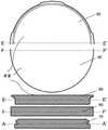
EP0512456A1介绍了一种靶设计,其利用沿靶周面的多个凸起,所述凸起允许靶可被转动到沉积室的固定机构中。据说靶凸起与沉积室的配对体相互作用,类似于“卡口锁”。这种“标准靶”设计的示例图如图8所示。类似于EP0393344A1,在EP0512456A1中描述了活动散热板的背压被用来将靶板压紧到固定机构上,这保证了靶背面与散热板之间的良好热接触。在此尝试中,包括凸起在内的整个靶板由待蒸发材料制造,但这在靶的卡口区域中造成相当高的应力,因此并不适用于脆性靶材情况。EP0512456A1 describes a target design that utilizes a plurality of projections along the perimeter of the target that allow the target to be rotated into the securing mechanism of the deposition chamber. The target protrusions are said to interact with counterparts in the deposition chamber, similar to a "bayonet lock". An example diagram of this "standard target" design is shown in Figure 8. Similar to EP0393344A1, it is described in EP0512456A1 that the back pressure of the movable heat sink is used to press the target plate against the fixing mechanism, which ensures a good thermal contact between the back of the target and the heat sink. In this attempt, the entire target plate, including the protrusions, was made of the material to be evaporated, but this caused rather high stress in the bayonet area of the target and was therefore not suitable for brittle targets.
过去,WO2014166620A1曾披露一种改善在溅射中的脆性靶的耐用性的想法。在那里,脆性靶材沿着经常会看到开裂的靶板外径被高强度钢替代。尽管如此,WO2014166620A1所建议的解决方案不适合由脆性材料制成的靶在电弧蒸发过程中作为阴极的工作。在某些情况下仍然存在靶座可能蒸发的危险。In the past, WO2014166620A1 has disclosed an idea to improve the durability of brittle targets in sputtering. There, the brittle target is replaced with high-strength steel along the outer diameter of the target plate where cracking is often seen. Nevertheless, the solution proposed by WO2014166620A1 is not suitable for the operation of targets made of brittle materials as cathodes during arc evaporation. In some cases there is still a risk that the target mount may evaporate.
因此,本发明试图克服已知靶形状的缺点,在此脆性靶材通常在作为阴极在PVD工艺中工作时遇到断裂问题。Accordingly, the present invention seeks to overcome the disadvantages of known target shapes, where brittle targets typically experience fracture problems when operating as cathodes in PVD processes.
因此,在本发明中已做出尝试来消除引起开裂的危险,做法是完成一种新型靶设计而不会使靶座的第二材料暴露在电弧或溅射等离子体下。Accordingly, an attempt has been made in the present invention to eliminate the risk of causing cracking by implementing a new target design without exposing the second material of the target holder to arcing or sputtering plasma.
通常,脆性损坏的原因假设是源于几个因素。其中一个因素是在电弧蒸发或溅射过程中的靶内局部应力发展变化。具有高熔点和/或六角晶体结构的靶材例如像元素Cr、Mo、W等、或者复合靶例如Ti-Cr、Mo-Cr、Mo-Hf和高熔点元素或靶材的其它二元或三元混合物易于脆性损坏。尤其在电弧蒸发过程中,局部加热发生在靶表面上,而靶背面一般被直接或间接冷却。在等离子体侧的相较于冷却侧的不同的热膨胀可能在工作中导致靶内高应力,其叠加上来自压紧在靶背面上的散热板的机械应力。就此而言,陶瓷靶材例如像硼化物如TiB2或氮化物如TiN、CrN或氧化物也是相似的。其它因素是这种靶材的一般低的热胀系数和/或低导热率,其可能促成靶内热应力发展变化。除此之外,靶设计必须保证靶在工作中被导电接通且良好冷却。In general, the cause of brittle failure is assumed to be due to several factors. One of these factors is the localized stress development within the target during arc evaporation or sputtering. Targets with high melting point and/or hexagonal crystal structure for example like elements Cr, Mo, W etc., or composite targets such as Ti-Cr, Mo-Cr, Mo-Hf and other binary or ternary of high melting point elements or targets Meta mixes are prone to brittle damage. Particularly during arc evaporation, localized heating occurs on the surface of the target, while the backside of the target is typically cooled directly or indirectly. The different thermal expansion on the plasma side compared to the cooling side can lead to high stresses in the target during operation, which are superimposed on the mechanical stresses from the heat sink pressed against the backside of the target. In this regard, ceramic targets such as, for example, borides such as TiB2 or nitrides such as TiN, CrN or oxides are also similar. Other factors are the generally low coefficient of thermal expansion and/or low thermal conductivity of such targets, which may contribute to thermal stress development within the target. In addition to this, the target design must ensure that the target is electrically connected and well cooled during operation.
在电弧蒸发中,电弧斑的运动可通过各种不同技术被影响,例如如借助允许自由电子充分结合至阳极的局部硬件布置或恒定的或可变的磁场布置的电弧转向技术。但通常观察到电弧斑移动越过整个靶面,尤其当没有采用电弧转向技术时。此电弧蒸发模式被称为“随机电弧”运动。在现有技术的靶设计解决方案中,打算利用由第二材料构成的靶座来克服机械靶的不稳定性,例如像在WO2014166620A1中那样。但是,该靶座通常具有与靶厚度一样的高度并且围绕待蒸发的靶材形成一个“笼”,其可能导致在电弧蒸发情况下自靶座无意蒸发出第二材料。In arc evaporation, the motion of the arc spot can be influenced by a variety of different techniques, such as arc steering techniques by means of local hardware arrangements or constant or variable magnetic field arrangements that allow sufficient binding of free electrons to the anode. However, it is often observed that the arc spot moves across the entire target surface, especially when arc steering techniques are not employed. This arc evaporation pattern is referred to as "random arc" motion. In the target design solutions of the prior art, it is intended to overcome the instability of the mechanical target by using a target mount composed of a second material, for example as in WO2014166620A1. However, the target holder typically has the same height as the target thickness and forms a "cage" around the target to be evaporated, which may result in unintentional evaporation of the second material from the target holder in the event of arc evaporation.
发明人于是提出一种用于改善脆性靶材的机械稳定性且进而改善靶面承受热负荷的能力的解决方案,而没有应用朝向靶面蒸发区的第二材料。本发明的靶设计想要适用于电弧蒸发,但也可以被用于DC溅射或RF溅射以及HIPIMS。The inventors then propose a solution for improving the mechanical stability of the brittle target and thus the ability of the target surface to withstand thermal loads, without applying a second material towards the evaporation zone of the target surface. The target design of the present invention is intended to be suitable for arc evaporation, but can also be used for DC sputtering or RF sputtering as well as HIPIMS.
发明目的Purpose of invention
本发明的目的是提供一种靶组件,其允许在电弧蒸发工艺以及溅射工艺中的断裂韧度和/或抗弯强度有限的靶材的安全、无断裂且经济的作业。本发明的靶组件优选应该允许只使要在涂覆工艺中蒸发的靶材暴露出来。因此,仅靶材而没有靶座的第二材料在溅射中朝向电弧放电或等离子体。It is an object of the present invention to provide a target assembly that allows safe, fracture-free and economical handling of targets with limited fracture toughness and/or flexural strength in arc evaporation processes as well as in sputtering processes. The target assembly of the present invention should preferably allow exposure of only the target material to be evaporated during the coating process. Thus, only the target material, and the second material without the target holder, is directed towards the arc discharge or plasma during sputtering.
本发明说明Description of the invention
本发明的靶组件包括本发明的靶10和保持机构20,分别如附图1和图2示意性所示。优选地,靶10和保持机构20与锁定机构30和弹簧40组合使用,分别如图3、图4和图5示意性所示。靶10显示出正面,其暴露在电弧或等离子体放电下。靶背面包括特定的几何形状特征,其在工作中产生几项功能和相关优点,例如像:The target assembly of the present invention includes a
-使用暴露在电弧或等离子体放电下的整个靶面用于蒸发靶材,- use the entire target surface exposed to an arc or plasma discharge for evaporating the target,
-在广泛的应用范围内使用靶,- the use of targets in a wide range of applications,
-靶与靶保持机构20的组合,- the combination of target and
-靶的良好的电气性能和改善的热学性能,- good electrical properties and improved thermal properties of the target,
-脆性靶材在高温工作时的改善的耐受性,- improved tolerance of brittle targets when operating at high temperatures,
-典型脆性靶材的使用,例如具有六角晶体结构和/或高熔点的材料,像耐火金属(如Cr、Mo、W)、这样的金属的混合物、各种不同的氧化物、碳化物和硼化物。- Use of typical brittle targets, such as materials with hexagonal crystal structure and/or high melting point, like refractory metals (eg Cr, Mo, W), mixtures of such metals, various oxides, carbides and boron matter.
本发明的靶设计主要打算用于盘状靶,但如果对靶保持机构施以小改动,本发明的概念也可以被用到板状靶。因此,为了清楚起见,以下讨论仅针对盘状几何形状。The target design of the present invention is primarily intended for use with disc-shaped targets, but the concepts of the present invention can also be applied to plate-shaped targets with minor modifications to the target retention mechanism. Therefore, for the sake of clarity, the following discussion is only for the disc geometry.
本发明的靶设计可以被应用到任何靶材上以用于电弧或溅射工艺,但对于脆性靶材最合适。The target design of the present invention can be applied to any target for arc or sputtering processes, but is most suitable for brittle targets.
在本申请的上下文中,词语“卡口”或“卡口锁”是指锁定机构,借此靶10和/或靶保持机构20的任何凸起做到与相应的配对体接合。配对体可以是靶保持机构20或者替代地是用于在沉积室内接纳靶的冷却机构(本申请未进一步讨论)。卡口锁的凸起因此装配到配对体的相应的底切或开口中。本发明的靶组件包括两个卡口锁。第一卡口锁,其在靶保持机构20中接触靶10,和第二卡口锁,其将本发明的整个靶组件固定在沉积室的冷却机构中。在靶10和/或靶保持机构20转动之后,各自凸起的和配对体的表面相互对置。当压力通过冷却机构被施加在靶的背面上时,各个凸起和对应的对置配对体表面接合并“锁定”本发明的靶组件。In the context of this application, the words "bayonet" or "bayonet lock" refer to a locking mechanism whereby any protrusion of the
本发明的靶的直径几乎可以是任何数字,其被选择为满足各个涂覆设备的要求。商业上可获得的电弧、溅射或HIPIMS系统的典型的靶外径范围为45~200毫米、优选是60~150毫米。在一个具体例子中,靶直径被选为150毫米。The diameter of the target of the present invention can be almost any number selected to meet the requirements of the individual coating equipment. Typical target outer diameters for commercially available arc, sputtering or HIPIMS systems range from 45 to 200 mm, preferably 60 to 150 mm. In one specific example, the target diameter was chosen to be 150 mm.
在根据本发明的靶组件中,如在图1和图5中示意性所示的本发明的靶10被构造成能装配到保持机构20中,它例如可以是如图2和图5示意性所示的高强度钢卡口环20。靶10包括用于接纳保持机构20的机构,其例如可以是作为卡口锁与保持机构20合作的凸起。为了将它们半锁定而需要靶10相对于保持机构20顺时针或逆时针相对转动。为了防止反转危险并将它们完全锁定或防止偶然拆分,优选采用锁定机构30,其如图3和图5举例所示,例如可以是带有固定结构的定中环。靶组件于是可以通过弹簧40被固定(见图4和图5),弹簧防止可选的锁定机构30松脱离保持机构20和靶10。当所有部分被组装在一起且正确锁定时,组装的靶可在生产中被用作标准靶。不需要用于靶的其它硬件或操作。在靶使用寿命到头时,组装的靶可以容易地被拆下,并且部件20、30和40可以又被再用于下一个靶。In a target assembly according to the present invention, the
本发明的其它细节和优选实施例:Additional details and preferred embodiments of the invention:
本发明的靶包括周向凹面12,该周向凹面形成在暴露于蒸发下的正面将,用于使靶保持机构“躲开”电弧放电或等离子体。凹面12将靶正面与朝向靶背面的靶体界定分开,由此形成小于D1的靶内径D2。突出超过内径D2的靶外径D1部分被称为靶的第一部分并且显示出靶鼻11。靶内径D2的区域被称为第二靶部分。这可以从沿图1的轴线A-A'和B-B'的靶10的横截面中看到。另外,靶包括至少两个、优选三个或以上的靶凸起14,它们在径向上沿靶周分布。这些靶凸起14允许在靶保持机构20中固定所述靶,并且如果从靶正面看的话不得突出超过靶的外径D1。此条件应该在径向尺寸方面为保持机构20留下足够空间。带有靶凸起14的靶部分被称为第三靶部分。The target of the present invention includes a circumferential
靶还可以包括至少两个、优选三个或以上的靶槽16,它们也在径向上沿着靶背面分布且伸入靶体,如图1示意所示的那样。这些靶槽16以必要的程度深入靶中以便完全接纳锁定机构30。The target may also comprise at least two, preferably three or
通常,脆性材料中的每个切口被认为是典型的开裂源。不同于现有技术的盘状靶或板状靶,发明人出乎意料地发现所提出的包括周向凹面12、靶凸起14和可选的靶槽16的靶10能相比于如从现有技术例如WO2014166620A1中知道的“笼状”靶座在工作中承受更高的机械载荷。假定是所述机械载荷通过靶凸起14与靶保持机构的内凸起24的相互作用而更好地分散,如下所解释的那样。In general, each cut in a brittle material is considered a typical source of cracking. Unlike the disk or plate targets of the prior art, the inventors have unexpectedly found that the proposed
工作中的高负荷的出现一般源于冷却机构在靶背面上的压力以及正面和背面的不同热膨胀,热膨胀的起因是由电弧或等离子体放电造成的在靶正面上的高温度。出乎发明人意料地,本发明的靶设计与现有技术的靶设计相比允许在较高的电弧电流或增大的溅射功率下工作。The high loads in operation generally arise from the pressure of the cooling mechanism on the back of the target and the differential thermal expansion of the front and back, which is caused by high temperatures on the front of the target caused by arcing or plasma discharges. Unexpectedly by the inventors, the target designs of the present invention allow operation at higher arc currents or increased sputtering powers compared to prior art target designs.
靶设计的几个条件被发现是有利的(也见图6):Several conditions for target design were found to be favorable (see also Figure 6):
-凹面12的径向深度dr由靶外径D1和靶内径D2之差的一半来表示,或者应该在D1的2~7.5%、优选是2.5~4.5%范围内。- The radial depth dr of the concave surface12 is represented byhalf the difference between the target outer diameter D1 and the target inner diameter D2, or should be in the rangeof2-7.5 % of D1, preferably 2.5-4.5%.
-靶鼻厚度tn可在dr的60%至150%之间,而利用75%比例已获得最佳结果,- the target nose thickness tn can be between 60% and 150% of dr , while the best results have been obtained with a 75% scale,
-凹面高度依赖于靶保持机构20的内凸起24的厚度。- The height of the concave surface is dependent on the thickness of the
最佳值的选择强烈依赖于靶厚度和直径,但可被看作靶设计的经验规则。The choice of the optimum value is strongly dependent on target thickness and diameter, but can be seen as a rule of thumb for target design.
这例如意味着,对于外径D1为150毫米的靶,凹面深度dr可被选择为在3.0~11.25毫米、优选是3.8~6.8毫米之间,其结果是,对于产生的靶鼻厚度tn是75%的dr,为2.3~8.4毫米、优选是2.9~5.1毫米。This means, for example, that for a target with an outer diameter D1 of 150 mm, the concave depth dr can be chosen to be between 3.0 and 11.25 mm, preferably between 3.8 and 6.8 mm, with the result that for the resulting target nose thickness tn is 75% ofdr and is 2.3 to 8.4 mm, preferably 2.9 to 5.1 mm.
对于本发明靶设计最重要的条件是也称为靶卡口的靶凸起14的轴向厚度tb。已经发现,利用本发明的靶设计,如上所述的机械应力优选通过靶凸起14被分散到靶保持机构20中。tb的最小值取决于如以下的几个因素:The most important condition for the target design of the present invention is the axial thickness tb of the
-靶外径(D1)和靶内径(D2)的几何形状,- the geometry of the target outer diameter (D1 ) and the target inner diameter (D2 ),
-接触冷却机构的靶背面的表面面积,- the surface area of the back of the target in contact with the cooling mechanism,
-在工作中冷却机构朝向靶的压力,- the pressure of the cooling mechanism towards the target during operation,
-靶材的力学性能。- Mechanical properties of the target.
本领域技术人员可挑选最适合各个沉积源需求的几何形状因素。基本上,靶内径D2由此应该被选择为小到允许靶保持机构20的内凸起24有足够深度以顺利“钩卡”入靶10中。这保证了重叠的内凸起24和靶凸起14的足够大的表面面积以提供足够高的靶组件机械强度。另一方面,靶内径20应该尽量大以使在工作中有效用于蒸发的靶体积最大化。One skilled in the art can select the geometry factor that best suits the needs of each deposition source. Basically, the target inner diameter D2 should thus be chosen to be small enough to allow the
发明人发现了,作为经验法则,tb的最小值应该是初始靶厚度ts的15%、优选25%、甚至更优选是33%,也见图1和图6。在ts为12毫米的铬靶情况下,已经发现靶凸起tb的厚度应该是至少1.8毫米、优选3.6毫米、甚至更优选是4毫米。另外,tb的最大值由保持机构20的内凸起24的最小厚度限定。tb最佳值的选择于是也显著依赖于靶厚度和直径,但可以被视作靶设计的经验法则。tb的最大值由靶保持机构20的内凸起24的沿轴向的最小厚度来限定,以满足力学要求并防止在工作中的靶保持机构20的内凸起24的机械损坏。另外,必须在此设计中预见在靶凸起14和靶保持机构20的内凸起24之间的小间隙以容许顺畅组装。初始靶厚度ts的85%的最大值被发现满足这些要求。The inventors have found that, as a rule of thumb, the minimum value oftb should be 15%, preferably 25%, even more preferably 33% of the initial target thicknessts , see also Figures 1 and 6 . In the case of a chromium target with ats of 12 mm, it has been found that the thickness of the target protrusiontb should be at least 1.8 mm, preferably 3.6 mm, even more preferably 4 mm. Additionally, the maximum value of tb is defined by the minimum thickness of the
散热板的压强一般在1至5巴之间。但是,靶材的机械性能和在此尤其是抗弯强度是难以确定的,因为它主要取决于靶材成分、晶粒尺寸、制造方法。The pressure of the heat sink is generally between 1 and 5 bar. However, the mechanical properties of the target and here in particular the flexural strength are difficult to determine, since it depends mainly on the target composition, the grain size, the manufacturing method.
图6的示意图从具有初始靶厚度ts的原始靶横截面(外实线)中示出了仅具有靶厚度te的很少靶材(由虚线所围的阴影线区表示)在使用寿命到头时余留下。tn和dr的上述值是重要的,因为靶应该在其使用寿命到头时甚至更机械稳定。于是,甚至可以使用脆性靶直至关键的较小靶厚度te,在以保守方式使用给定比率的情况下可达以上情况。The schematic diagram of FIG. 6 shows from the original target cross-section (outer solid line) with initial target thicknessts that very few targets with only target thickness te (represented by the hatched area surrounded by dashed lines) over the service life Left over at the end. The above-mentioned values of tn and dr are important because the target should be even more mechanically stable at the end of its useful life. Thus, even brittle targets can be used up to a critically small target thicknesste , which can be achieved using given ratios in a conservative manner.
但是,值tn和dr可以依赖于所用靶材(例如金属、陶瓷或金属和/或陶瓷的混合物)及其具体性能以及源于例如在靶背侧的散热板的机械载荷或者其它几何形状考虑。However, the values tn and dr may depend on the target material used (eg metal, ceramic or mixture of metals and/or ceramics) and its specific properties as well as mechanical loads or other geometries resulting from eg a heat sink on the backside of the target consider.
在图1所示的金属铬靶的例子中示出了四个靶凸起14,它们沿着靶背面的周向均匀分布。靶凸起的数量以及其周向长度必须被本领域技术人员选择以满足各个沉积设备的要求,其目标是要获得靶的最佳稳定性。In the example of the metallic chromium target shown in FIG. 1 four
用于在沉积过程中被蒸发的靶正面一开始是平面。该正面还可以如此被机加工(例如通过车削、铣削、磨削、研磨或电火花加工),即靶的表面粗糙度被减小。按照相似方式,外径和内径D1和D2以及靶凸起14、靶槽16和所造成的凹面12可以被机加工。如果获得靶表面粗糙度Ra<5微米、优选是Ra<3.5微米,则得到最佳结果。The front side of the target for being evaporated during deposition is initially flat. The front side can also be machined (eg by turning, milling, grinding, grinding or electrical discharge machining) in such a way that the surface roughness of the target is reduced. In a similar manner, the outer and inner diameters D1 and D2 and the
如图2示意性所示,对应的靶保持机构20用于将靶10连接至冷却机构和进而沉积室,包括至少两组外凸起和内凸起。外凸起22用于在沉积室内在沉积源的卡口锁中锁定整个靶组件,其使靶背面接触散热板。本领域专家知晓对应的机构,因此无需进一步深入解释。但是,保持机构20的内凸起24用于被装配入在靶凸起14和靶鼻11之间留下的对应区域中,即它们装配入凹面12中。内凸起24和对应的靶凸起14的数量必须相同。外凸起22的和内凸起24的数量可以彼此不同,但优选它们具有相同的数量,与如图2举例所示。如果选择四对靶凸起14和保持机构的内凸起24,则这种布置结果是最佳的。如以上所解释地,靶凸起14需要显示出足够高的机械强度和进而在靶厚度轴向上的至少最小厚度。保持机构20应该显示出如下高度,在与靶10组装好之后,靶10的背面与靶保持机构20的背面齐平。这允许靶背面完全接触沉积室的靶冷却机构。As shown schematically in FIG. 2, a corresponding
在所选例子中,靶保持机构20和靶10可被轻松组装,并且通过靶10相对于保持机构20的45度顺时针运动来获得半锁定状态。所产生的靶凸起14和保持机构20的内凸起24的重叠保证了作用于靶背面的机械载荷被有效传导入保持机构中,并且机械应力在靶表面和靶外径处被降低。专家知晓如何选择外凸起22和内凸起24的对应厚度以保证对靶10以及沉积室或冷却系统的兼容性。专家必须预见到用于在单独零件组装时的便于运动的足够间隙。图2的横截面沿着轴线C-C'和D-D'示出了保持机构20,在此是高强度不锈钢环,可如何被成形以满足上述要求的一些示例性细节。In the selected example, the
在本发明的另一实施例中采用了锁定机构30和弹簧40。因此,必须预见到在靶10的径向上的一个附加阶梯结构(图6中的D4),其将靶凸起14与朝向靶背面的靶体界定分开。附加地,保持机构20能包括靶座槽26,它们被如此加工,即在靶10与保持机构20组装且被转动而达到半锁定状态之后直接与靶体的靶槽16相对。可选的靶槽16和靶座槽26用于如此接纳可选的锁定机构30的固定耳32,即转动运动可被有效锁止。因此,靶槽16以及靶座槽26的深度分别由所用的锁定机构30的厚度决定。在这种情况下,1毫米厚的高强度钢环被用作锁定机构(例如相应参见图2和图5)。但是该锁定机构30的厚度也可以高许多,例如2~5毫米,取决于靶厚度和直径。固定耳32应从固定环沿径向伸入靶座槽26但不超出。相似地,固定耳32的相反侧沿径向伸入靶槽16。Locking
保持机构20可以包括周向内凹面28,其可以在图2的横截面C-C'中看到。内凹面28具有仅1至2毫米的深度并且可以被认为是弹簧40的接纳部。当靶组件如上所述地由靶10连同保持机构20和可选的锁定机构30构成时,弹簧40容易在余下的周向沟槽内(例如用手)被直接压在锁定机构30上。因为其弹簧特性,弹簧40张开并且被保持机构20的内凹面28接纳,在这里,它钩卡入并防止锁定机构30无意拆分。
如可以从图4的示意图中看到地,弹簧40在扁平弹簧40的两侧显示出钩42。这些钩可以在弹簧被安装时暗藏在保持机构20的靶座槽26内,它保证了整个靶组件的平整背面。这些钩42是用于在使用后方便操作且有意拆卸靶的机构。弹簧40也可以由任何金属、优选是不锈钢或高强度钢制造,其显示出足够高的弹簧特性并且优选是扁平的以便最佳装配到整个靶组件中。靶保持机构20的材料必须被选择成是导电的且在工作中承受出现的机械载荷,在此,不锈钢或高强度钢被发现能最佳满足这些要求,但其它的金属或导电陶瓷是可想到的。As can be seen from the schematic diagram of FIG. 4 , the
作为对于本发明的整个靶组件的边界条件,靶10的背面与保持机构20齐平是重要的。这种情况在图7中被示意性示出,在这里示出了组装的靶的横截面细节。重要的是所有“锋利”角部被避免了,意味着在机加工中的边缘半径应该不小于0.5毫米、优选不小于0.25毫米。As a boundary condition for the entire target assembly of the present invention, it is important that the backside of the
图5示意性示出本发明的靶组件的分解图,其包括靶10、靶保持机构20以及可选的锁定机构30和弹簧40。FIG. 5 schematically shows an exploded view of the target assembly of the present invention, including
本发明的靶组件的优点是靶保持机构20能用作用于冷却机构的适配接头和/或现有沉积设备的接纳部,假定现有涂覆设备的接纳部显示出卡口锁作为用于本发明的靶10和/或靶锁定机构20的配对体。于是,已安装的冷却机构或沉积设备的昂贵改动是不需要的。An advantage of the target assembly of the present invention is that the
借助将所有相同的投射区暴露在电弧或等离子体放电下的典型的标准设计的本发明的靶组件的另一优点如图8示意性所示。从此对比中,人们可以清楚看到本发明的经济优点,这是因为本发明的靶10需要相比于其它靶更少的材料,而与此同时克服了“标准”靶的缺点。横截面A-A'涉及本发明的靶10,横截面F-F'涉及简单的盘状靶90,横截面E-E'涉及现有技术的靶80。所有的靶完全由待蒸发的材料制造,但是,其制造所需的材料量不同。如上所述解释地,现有技术的靶80显示出多个凸起,它们是卡口锁的一部分并且不适于脆性靶材。为了获得暴露在等离子体下的相同的靶表面面积,完整的盘状靶90必须以较大直径来制造,因为将靶固定至散热板的骨架结构遮挡了在边缘区域内的相当多的靶材。所述材料不能被蒸发并因此为生产“损失”掉。在昂贵靶材的情况下,未用的靶量变得具有经济重要性。但是,本发明的靶需要最少量的靶材,只使待蒸发材料暴露于电弧或等离子体放电,最终改善机械稳固性,其保证在高度的可能靶消耗下的安全运行。Another advantage of the target assembly of the present invention is shown schematically in FIG. From this comparison, one can clearly see the economic advantages of the present invention, since the
本发明的靶组件有助于克服在电弧沉积以及等离子体加工过程中的脆性断裂。容易安装和在使用之后拆卸。它可以被多次使用并且允许通常昂贵的靶材的更多消耗。在铬的情况下,它有助于避免开裂和需要提前更换靶,这有效延长靶的使用寿命、节约制造成本和生产时间。The target assembly of the present invention helps to overcome brittle fracture during arc deposition as well as plasma processing. Easy to install and remove after use. It can be used multiple times and allows for more consumption of normally expensive targets. In the case of chromium, it helps to avoid cracking and the need for early target replacement, which effectively extends target life, saving manufacturing costs and production time.
Claims (11)
Translated fromChineseApplications Claiming Priority (3)
| Application Number | Priority Date | Filing Date | Title |
|---|---|---|---|
| CH00708/17 | 2017-06-01 | ||
| CH7082017 | 2017-06-01 | ||
| PCT/EP2018/064281WO2018220067A1 (en) | 2017-06-01 | 2018-05-30 | Target assembly for safe and economic evaporation of brittle materials |
Publications (2)
| Publication Number | Publication Date |
|---|---|
| CN110892502A CN110892502A (en) | 2020-03-17 |
| CN110892502Btrue CN110892502B (en) | 2022-10-04 |
Family
ID=64454461
Family Applications (1)
| Application Number | Title | Priority Date | Filing Date |
|---|---|---|---|
| CN201880045797.3AActiveCN110892502B (en) | 2017-06-01 | 2018-05-30 | Target assembly for safe and economical evaporation of brittle materials |
Country Status (7)
| Country | Link |
|---|---|
| US (1) | US11158491B2 (en) |
| EP (1) | EP3631837B1 (en) |
| JP (1) | JP7153290B2 (en) |
| KR (1) | KR102674265B1 (en) |
| CN (1) | CN110892502B (en) |
| MX (1) | MX2019014425A (en) |
| WO (1) | WO2018220067A1 (en) |
Families Citing this family (19)
| Publication number | Priority date | Publication date | Assignee | Title |
|---|---|---|---|---|
| JP1646505S (en)* | 2018-12-07 | 2019-11-25 | ||
| US11961723B2 (en)* | 2018-12-17 | 2024-04-16 | Applied Materials, Inc. | Process kit having tall deposition ring for PVD chamber |
| USD933725S1 (en)* | 2019-02-08 | 2021-10-19 | Applied Materials, Inc. | Deposition ring for a substrate processing chamber |
| USD942516S1 (en)* | 2019-02-08 | 2022-02-01 | Applied Materials, Inc. | Process shield for a substrate processing chamber |
| USD979524S1 (en)* | 2020-03-19 | 2023-02-28 | Applied Materials, Inc. | Confinement liner for a substrate processing chamber |
| USD941371S1 (en)* | 2020-03-20 | 2022-01-18 | Applied Materials, Inc. | Process shield for a substrate processing chamber |
| USD941372S1 (en)* | 2020-03-20 | 2022-01-18 | Applied Materials, Inc. | Process shield for a substrate processing chamber |
| USD934315S1 (en)* | 2020-03-20 | 2021-10-26 | Applied Materials, Inc. | Deposition ring for a substrate processing chamber |
| USD933726S1 (en)* | 2020-07-31 | 2021-10-19 | Applied Materials, Inc. | Deposition ring for a semiconductor processing chamber |
| US11581166B2 (en) | 2020-07-31 | 2023-02-14 | Applied Materials, Inc. | Low profile deposition ring for enhanced life |
| USD1042373S1 (en) | 2022-03-18 | 2024-09-17 | Applied Materials, Inc. | Sliding ring for an interlocking process kit for a substrate processing chamber |
| USD1042374S1 (en)* | 2022-03-18 | 2024-09-17 | Applied Materials, Inc. | Support pipe for an interlocking process kit for a substrate processing chamber |
| USD1055006S1 (en)* | 2022-03-18 | 2024-12-24 | Applied Materials, Inc. | Support ring for an interlocking process kit for a substrate processing chamber |
| JP2025521046A (en) | 2022-07-08 | 2025-07-04 | トーソー エスエムディー,インク. | Dynamic Vacuum Seal System for Physical Vapor Deposition Sputtering Applications |
| USD1069863S1 (en)* | 2022-08-04 | 2025-04-08 | Applied Materials, Inc. | Deposition ring of a process kit for semiconductor substrate processing |
| USD1064005S1 (en) | 2022-08-04 | 2025-02-25 | Applied Materials, Inc. | Grounding ring of a process kit for semiconductor substrate processing |
| KR102631051B1 (en) | 2022-09-01 | 2024-01-30 | 주식회사 금륜Eng | Jig device for inspection of parking sprags for CVT |
| USD1034493S1 (en)* | 2022-11-25 | 2024-07-09 | Ap Systems Inc. | Chamber wall liner for a semiconductor manufacturing apparatus |
| AT18282U1 (en)* | 2023-05-16 | 2024-08-15 | Plansee Composite Mat Gmbh | Segmented ring target |
Citations (3)
| Publication number | Priority date | Publication date | Assignee | Title |
|---|---|---|---|---|
| CN1107523A (en)* | 1993-11-24 | 1995-08-30 | 应用材料有限公司 | Integrated sputter target assembly |
| CA2218736A1 (en)* | 1995-05-11 | 1996-11-14 | Steven D. Hurwitt | Sputtering apparatus with isolated coolant and sputtering target therefor |
| CN105039915A (en)* | 2015-07-28 | 2015-11-11 | 东莞市汇成真空科技有限公司 | A Vacuum Cathode Arc Source with Discharge Arc Spots Covering the Target Surface |
Family Cites Families (14)
| Publication number | Priority date | Publication date | Assignee | Title |
|---|---|---|---|---|
| US4820397A (en)* | 1988-04-04 | 1989-04-11 | Tosoh Smd, Inc. | Quick change sputter target assembly |
| JP2688242B2 (en)* | 1988-11-25 | 1997-12-08 | 東京エレクトロン株式会社 | Sputtering apparatus and sputtering method |
| EP0393344A1 (en) | 1989-04-20 | 1990-10-24 | Balzers Aktiengesellschaft | Targets supporting device for sputtering sources and procedure for maintaining a target in a support |
| EP0512456B1 (en) | 1991-05-08 | 1997-06-18 | Balzers Aktiengesellschaft | Process for fitting and removal of a target plate in a vacuum processing chamber, fitting therefor, target plate and vacuum chamber |
| DE4223091C1 (en)* | 1992-07-14 | 1993-07-01 | Vtd-Vakuumtechnik Dresden Gmbh, O-8017 Dresden, De | Water cooled holder for inserted exchangeable target - comprises housing, cooling plate and axially freely movable metal bellows, vacuum arc discharge vapour deposition appts. |
| DE4410466C1 (en)* | 1994-03-25 | 1995-09-14 | Balzers Hochvakuum | Target holder, target and use thereof, |
| EP0951049A1 (en)* | 1998-04-16 | 1999-10-20 | Balzers Aktiengesellschaft | Retaining ring, target and its manufacturing procedure |
| US6287435B1 (en) | 1998-05-06 | 2001-09-11 | Tokyo Electron Limited | Method and apparatus for ionized physical vapor deposition |
| US6551470B1 (en)* | 1999-06-15 | 2003-04-22 | Academy Precision Materials | Clamp and target assembly |
| ES2774167T3 (en)* | 2008-09-02 | 2020-07-17 | Oerlikon Surface Solutions Ag Pfaeffikon | Coating device for coating a substrate, as well as a method for coating a substrate |
| AT13609U1 (en)* | 2012-09-17 | 2014-04-15 | Plansee Se | Tubular target |
| US20140174911A1 (en)* | 2012-12-21 | 2014-06-26 | Intermolecular, Inc. | Methods and Systems for Reducing Particles During Physical Vapor Deposition |
| WO2014166621A1 (en) | 2013-04-08 | 2014-10-16 | Oerlikon Trading Ag, Trübbach | Centering of a plate in a holder both at room temperatures and at higher temperatures |
| DE102013011068A1 (en)* | 2013-07-03 | 2015-01-08 | Oerlikon Trading Ag, Trübbach | Target age compensation method for performing stable reactive sputtering |
- 2018
- 2018-05-30CNCN201880045797.3Apatent/CN110892502B/enactiveActive
- 2018-05-30MXMX2019014425Apatent/MX2019014425A/enunknown
- 2018-05-30WOPCT/EP2018/064281patent/WO2018220067A1/ennot_activeCeased
- 2018-05-30EPEP18728374.2Apatent/EP3631837B1/enactiveActive
- 2018-05-30USUS16/618,786patent/US11158491B2/enactiveActive
- 2018-05-30KRKR1020197039028Apatent/KR102674265B1/enactiveActive
- 2018-05-30JPJP2019566116Apatent/JP7153290B2/enactiveActive
Patent Citations (3)
| Publication number | Priority date | Publication date | Assignee | Title |
|---|---|---|---|---|
| CN1107523A (en)* | 1993-11-24 | 1995-08-30 | 应用材料有限公司 | Integrated sputter target assembly |
| CA2218736A1 (en)* | 1995-05-11 | 1996-11-14 | Steven D. Hurwitt | Sputtering apparatus with isolated coolant and sputtering target therefor |
| CN105039915A (en)* | 2015-07-28 | 2015-11-11 | 东莞市汇成真空科技有限公司 | A Vacuum Cathode Arc Source with Discharge Arc Spots Covering the Target Surface |
Also Published As
| Publication number | Publication date |
|---|---|
| CN110892502A (en) | 2020-03-17 |
| MX2019014425A (en) | 2020-02-10 |
| US11158491B2 (en) | 2021-10-26 |
| BR112019025350A2 (en) | 2020-06-23 |
| KR20200012983A (en) | 2020-02-05 |
| JP2020521884A (en) | 2020-07-27 |
| JP7153290B2 (en) | 2022-10-14 |
| KR102674265B1 (en) | 2024-06-11 |
| EP3631837A1 (en) | 2020-04-08 |
| US20200090915A1 (en) | 2020-03-19 |
| EP3631837B1 (en) | 2021-01-27 |
| WO2018220067A1 (en) | 2018-12-06 |
Similar Documents
| Publication | Publication Date | Title |
|---|---|---|
| CN110892502B (en) | Target assembly for safe and economical evaporation of brittle materials | |
| US8911601B2 (en) | Deposition ring and electrostatic chuck for physical vapor deposition chamber | |
| US4820397A (en) | Quick change sputter target assembly | |
| JP5432971B2 (en) | Sliding member and manufacturing method thereof | |
| US9960021B2 (en) | Physical vapor deposition (PVD) target having low friction pads | |
| US8580092B2 (en) | Adjustable process spacing, centering, and improved gas conductance | |
| TW200935543A (en) | Wafer carrier with HUB | |
| EP3830864B1 (en) | Detachable thermal leveler | |
| CN109599319B (en) | Finned shutter disk for substrate processing chamber | |
| WO2012109069A2 (en) | Pvd sputtering target with a protected backing plate | |
| US20110139614A1 (en) | Sputtering target with an insulating ring and a gap between the ring and the target | |
| EP2420710B1 (en) | Faucet with wear-resistant valve component | |
| US20190301007A1 (en) | Thermally optimized rings | |
| US5863397A (en) | Target mounting apparatus for vapor deposition system | |
| KR20010050590A (en) | Extended life sputter targets | |
| US20030173216A1 (en) | Sputtertarget | |
| BR112019025350B1 (en) | TARGET SET FOR SAFE AND ECONOMIC EVAPORATION OF BRITTLE MATERIALS | |
| JP6374948B2 (en) | Arc evaporation source with permanent magnet | |
| CN110546298B (en) | Special-shaped sputtering target and preparation method thereof | |
| WO2018094022A1 (en) | Collimator for use in a physical vapor deposition chamber | |
| EP0070952A1 (en) | Wear resistant synchronizer ring | |
| EP2487275B1 (en) | Composite shielding | |
| Bloyce | Coatings for high performance pumps and compressors |
Legal Events
| Date | Code | Title | Description |
|---|---|---|---|
| PB01 | Publication | ||
| PB01 | Publication | ||
| SE01 | Entry into force of request for substantive examination | ||
| SE01 | Entry into force of request for substantive examination | ||
| GR01 | Patent grant | ||
| GR01 | Patent grant |