CN110891628B - blood purification device - Google Patents
blood purification deviceDownload PDFInfo
- Publication number
- CN110891628B CN110891628BCN201880041650.7ACN201880041650ACN110891628BCN 110891628 BCN110891628 BCN 110891628BCN 201880041650 ACN201880041650 ACN 201880041650ACN 110891628 BCN110891628 BCN 110891628B
- Authority
- CN
- China
- Prior art keywords
- blood
- flow path
- purification device
- purifier
- present
- Prior art date
- Legal status (The legal status is an assumption and is not a legal conclusion. Google has not performed a legal analysis and makes no representation as to the accuracy of the status listed.)
- Active
Links
Images


Classifications
- A—HUMAN NECESSITIES
- A61—MEDICAL OR VETERINARY SCIENCE; HYGIENE
- A61M—DEVICES FOR INTRODUCING MEDIA INTO, OR ONTO, THE BODY; DEVICES FOR TRANSDUCING BODY MEDIA OR FOR TAKING MEDIA FROM THE BODY; DEVICES FOR PRODUCING OR ENDING SLEEP OR STUPOR
- A61M1/00—Suction or pumping devices for medical purposes; Devices for carrying-off, for treatment of, or for carrying-over, body-liquids; Drainage systems
- A61M1/14—Dialysis systems; Artificial kidneys; Blood oxygenators ; Reciprocating systems for treatment of body fluids, e.g. single needle systems for hemofiltration or pheresis
- A61M1/16—Dialysis systems; Artificial kidneys; Blood oxygenators ; Reciprocating systems for treatment of body fluids, e.g. single needle systems for hemofiltration or pheresis with membranes
- A61M1/1621—Constructional aspects thereof
- A—HUMAN NECESSITIES
- A61—MEDICAL OR VETERINARY SCIENCE; HYGIENE
- A61M—DEVICES FOR INTRODUCING MEDIA INTO, OR ONTO, THE BODY; DEVICES FOR TRANSDUCING BODY MEDIA OR FOR TAKING MEDIA FROM THE BODY; DEVICES FOR PRODUCING OR ENDING SLEEP OR STUPOR
- A61M1/00—Suction or pumping devices for medical purposes; Devices for carrying-off, for treatment of, or for carrying-over, body-liquids; Drainage systems
- A61M1/34—Filtering material out of the blood by passing it through a membrane, i.e. hemofiltration or diafiltration
- A61M1/342—Adding solutions to the blood, e.g. substitution solutions
- A—HUMAN NECESSITIES
- A61—MEDICAL OR VETERINARY SCIENCE; HYGIENE
- A61M—DEVICES FOR INTRODUCING MEDIA INTO, OR ONTO, THE BODY; DEVICES FOR TRANSDUCING BODY MEDIA OR FOR TAKING MEDIA FROM THE BODY; DEVICES FOR PRODUCING OR ENDING SLEEP OR STUPOR
- A61M1/00—Suction or pumping devices for medical purposes; Devices for carrying-off, for treatment of, or for carrying-over, body-liquids; Drainage systems
- A61M1/14—Dialysis systems; Artificial kidneys; Blood oxygenators ; Reciprocating systems for treatment of body fluids, e.g. single needle systems for hemofiltration or pheresis
- A61M1/16—Dialysis systems; Artificial kidneys; Blood oxygenators ; Reciprocating systems for treatment of body fluids, e.g. single needle systems for hemofiltration or pheresis with membranes
- A—HUMAN NECESSITIES
- A61—MEDICAL OR VETERINARY SCIENCE; HYGIENE
- A61M—DEVICES FOR INTRODUCING MEDIA INTO, OR ONTO, THE BODY; DEVICES FOR TRANSDUCING BODY MEDIA OR FOR TAKING MEDIA FROM THE BODY; DEVICES FOR PRODUCING OR ENDING SLEEP OR STUPOR
- A61M1/00—Suction or pumping devices for medical purposes; Devices for carrying-off, for treatment of, or for carrying-over, body-liquids; Drainage systems
- A61M1/14—Dialysis systems; Artificial kidneys; Blood oxygenators ; Reciprocating systems for treatment of body fluids, e.g. single needle systems for hemofiltration or pheresis
- A61M1/30—Single needle dialysis ; Reciprocating systems, alternately withdrawing blood from and returning it to the patient, e.g. single-lumen-needle dialysis or single needle systems for hemofiltration or pheresis
- A—HUMAN NECESSITIES
- A61—MEDICAL OR VETERINARY SCIENCE; HYGIENE
- A61M—DEVICES FOR INTRODUCING MEDIA INTO, OR ONTO, THE BODY; DEVICES FOR TRANSDUCING BODY MEDIA OR FOR TAKING MEDIA FROM THE BODY; DEVICES FOR PRODUCING OR ENDING SLEEP OR STUPOR
- A61M1/00—Suction or pumping devices for medical purposes; Devices for carrying-off, for treatment of, or for carrying-over, body-liquids; Drainage systems
- A61M1/34—Filtering material out of the blood by passing it through a membrane, i.e. hemofiltration or diafiltration
Landscapes
- Health & Medical Sciences (AREA)
- Heart & Thoracic Surgery (AREA)
- Urology & Nephrology (AREA)
- Hematology (AREA)
- Anesthesiology (AREA)
- Biomedical Technology (AREA)
- Engineering & Computer Science (AREA)
- Life Sciences & Earth Sciences (AREA)
- Animal Behavior & Ethology (AREA)
- General Health & Medical Sciences (AREA)
- Public Health (AREA)
- Veterinary Medicine (AREA)
- Vascular Medicine (AREA)
- Emergency Medicine (AREA)
- External Artificial Organs (AREA)
Abstract
Description
Translated fromChinese技术领域technical field
本发明涉及一种血液净化装置。The invention relates to a blood purification device.
背景技术Background technique
作为公开了能够检测静脉侧穿刺针的脱离的血液净化装置的结构的在先文献,有日本专利特开2007-20990号公报(专利文献1)。专利文献1中记载的血液透析装置包括透析器、血液回路、血液泵、透析液回路、以及超声波式血流计。Japanese Patent Application Laid-Open No. 2007-20990 (Patent Document 1) is a prior document disclosing the configuration of a blood purification device capable of detecting detachment of a venous puncture needle. The hemodialysis apparatus described in
现有技术文献prior art literature
专利文献patent documents
专利文献1:日本专利特开2007-20990号公报Patent Document 1: Japanese Patent Laid-Open No. 2007-20990
发明内容Contents of the invention
发明所要解决的技术问题The technical problem to be solved by the invention
专利文献1中记载的血液透析装置的血液回路与一般的血液净化装置的结构相同,由透析器的上游侧的动脉侧血液回路和透析器的下游侧的静脉侧血液回路构成,形成环。The blood circuit of the hemodialysis device described in
一般,血液净化装置配置在比透析室窄的病室等中,要求装置结构的简化。在形成有上述那样的环的血液净化装置中,由于必须分别穿刺动脉和静脉,因此,患者和医疗从业者的负担大。另外,有可能因穿刺针的脱离而导致失血量增多。Generally, a blood purification device is arranged in a patient room narrower than a dialysis room, etc., and simplification of the device structure is required. In the blood purification apparatus formed with the rings as described above, since the artery and the vein must be punctured separately, the burden on the patient and the medical practitioner is heavy. In addition, blood loss may increase due to detachment of the puncture needle.
本发明是鉴于上述问题而完成的,其目的在于提供一种血液净化装置,上述血液净化装置能够简化装置结构,并且能够抑制发生穿刺针脱离的情况下的失血量。The present invention has been made in view of the above problems, and an object of the present invention is to provide a blood purification device capable of simplifying the device structure and suppressing blood loss when a puncture needle is detached.
解决技术问题所采用的技术方案Technical solutions adopted to solve technical problems
基于本发明的血液净化装置包括血液净化器、血管进出流路、清洗液流路和排液流路。血液净化器通过半透膜分割为第一部和第二部。血管进出流路与血液净化器连接并且与第一部连通。清洗液流路连接到血液净化器并且与上述第一部连通。排液流路连接到血液净化器并且与上述第二部连通。在清洗液流路中设置有能够双向输送液体的血液泵。在血管进出流路和排液流路分别设置有开闭阀。The blood purification device based on the present invention includes a blood purifier, a blood vessel inlet and outlet flow path, a cleaning liquid flow path and a liquid discharge flow path. The blood purifier is divided into the first part and the second part by a semipermeable membrane. The blood vessel inlet and outlet flow path is connected with the blood purifier and communicated with the first part. The cleaning liquid flow path is connected to the blood purifier and communicates with the above-mentioned first part. The discharge flow path is connected to the blood purifier and communicates with the above-mentioned second part. A blood pump capable of bidirectionally delivering liquid is provided in the cleaning liquid flow path. On-off valves are respectively arranged in the blood vessel inlet and outlet flow path and the liquid discharge flow path.
在本发明的一个方式中,血液净化装置还包括分岔流路。分岔流路从清洗液流路分岔并且与血液净化器连接,以使清洗液流路与第二部连通。在在分岔流路设置有开闭阀。In one aspect of the present invention, the blood purification device further includes a branch flow path. The branch flow path is branched from the cleansing liquid flow path and connected to the blood purifier so that the cleansing liquid flow path communicates with the second part. An on-off valve is installed in the branch flow path.
在本发明的一个方式中,血液净化装置还包括分岔流路。分岔流路从清洗液流路分岔并与血液净化器连接,以使清洗液流路与第二部连通。在清洗液流路中的、清洗液流路和分岔流路的分岔部与血液净化器之间的部分设置有开闭阀。In one aspect of the present invention, the blood purification device further includes a branch flow path. The branch flow path is branched from the cleaning liquid flow path and connected to the blood purifier so that the cleaning liquid flow path communicates with the second part. An on-off valve is provided in a part of the cleaning liquid flow path between the branch of the cleaning liquid flow path and the branched flow path and the blood purifier.
发明效果Invention effect
根据本发明,能够使血液净化装置的结构简单,并且能够抑制发生穿刺针的脱离的情况下的失血量。According to the present invention, the structure of the blood purification device can be simplified, and the amount of blood loss when the puncture needle is detached can be suppressed.
附图说明Description of drawings
图1是表示本发明的实施方式1的血液净化装置的结构的回路图。FIG. 1 is a circuit diagram showing the configuration of a blood purification device according to
图2是表示本发明的实施方式1的血液净化装置的脱血行程的回路图。2 is a circuit diagram showing a blood removal process of the blood purification device according to
图3是表示本发明的实施方式1的血液净化装置的除水行程的回路图。3 is a circuit diagram showing a water removal process of the blood purification device according to
图4是表示本发明的实施方式1的血液净化装置的返血行程的回路图。Fig. 4 is a circuit diagram showing a blood return process of the blood purification device according to
图5是表示本发明的实施方式2的血液净化装置的结构的回路图。5 is a circuit diagram showing the configuration of a blood purification device according to
图6是表示本发明的实施方式2的血液净化装置的脱血行程的回路图。6 is a circuit diagram showing a blood removal process of the blood purification device according to
图7是表示本发明的实施方式2的血液净化装置的透析行程的回路图。7 is a circuit diagram showing a dialysis process of the blood purification apparatus according to
图8是表示本发明的实施方式2的血液净化装置的除水行程的回路图。8 is a circuit diagram showing a water removal process of the blood purification device according to
图9是表示本发明的实施方式2的血液净化装置的返血行程的回路图。Fig. 9 is a circuit diagram showing a blood return process of the blood purification device according to
图10是表示本发明的实施方式3的血液净化装置的结构的回路图。10 is a circuit diagram showing the configuration of a blood purification device according to
图11是表示本发明的实施方式3的血液净化装置的脱血行程的回路图。11 is a circuit diagram showing a blood removal process of the blood purification device according to
图12是表示本发明的实施方式3的血液净化装置的除水行程的回路图。12 is a circuit diagram showing a water removal process of the blood purification device according to
图13是表示本发明的实施方式3的血液净化装置的返血行程的回路图。Fig. 13 is a circuit diagram showing a blood return process of the blood purification device according to
具体实施方式Detailed ways
下面,参照附图来对本发明的各实施方式的血液净化装置进行说明。在以下的实施方式的说明中,对于图中的相同或相当部分标注相同符号,不再重复其说明。Hereinafter, blood purification devices according to embodiments of the present invention will be described with reference to the drawings. In the description of the following embodiments, the same or corresponding parts in the drawings are given the same reference numerals, and the description thereof will not be repeated.
(实施方式1)(Embodiment 1)
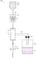
图1为表示本发明的实施方式1的血液净化装置的结构的回路图。如图1所示,本发明的实施方式1的血液净化装置100包括血液净化器110、血管进出流路120、清洗液流路130、以及排液流路150。FIG. 1 is a circuit diagram showing the configuration of a blood purification device according to
血液净化器110的内部例如通过中空纱膜等半透膜111分割为第一部10和第二部11。在本实施方式中,由半透膜111围起来的内侧的空间是第一部10,半透膜111的外侧的空间是第二部11。The inside of the
血管进出流路120连接到血液净化器110并且与第一部10连通。在血管进出流路120的与血液净化器110侧相反的一侧的端部设有穿刺针。在血管进出流路120上设有将血管进出流路120打开、关闭的第一开闭阀180。The blood vessel inlet and
清洗液流路130连接到血液净化器110并且与第一部10连通。清洗液流路130的与血液净化器110侧的相反的一侧的端部与储存有清洗液141的清洗液储液部140连接,上述清洗液141例如由生理盐水或透析液构成。在清洗液流路130中设置有能够双向输送液体的血液泵170。The cleaning
排液流路150连接到血液净化器110并且与第二部11连通。排液流路150的与血液净化器110侧相反的一侧的端部与储存排液161的排液储液部160连接。在排液流路150上设有将排液流路150打开、关闭的第二开闭阀190。The
下面,对本发明实施方式1的血液净化装置100的动作进行说明。Next, the operation of
在血液净化装置100的透析开始前,使用清洗液141分别起动血液净化器110、血管通路120、清洗液流路130以及排液流路150。Before the start of dialysis in
图2是表示本发明的实施方式1的血液净化装置的脱血行程的回路图。如图2所示,在本发明的实施方式1的血液净化装置100的脱血行程中,在第一开闭阀180打开、第二开闭阀190关闭的状态下,血液泵170向箭头2所示的吸入方向输送液体。其结果是,如箭头1所示,血液从血管进出流路120流入到血液净化器110的第一部10。通过血液净化器110的第一部10的血液流入到清洗液流路130。根据流入到清洗液流路130的血液的量,清洗液流路130内的清洗液141流入到清洗液储液部140。2 is a circuit diagram showing a blood removal process of the blood purification device according to
图3是表示本发明的实施方式1的血液净化装置的除水行程的回路图。如图3所示,在本发明的实施方式1的血液净化装置100的除水行程中,在第一开闭阀180关闭、第二开闭阀190打开的状态下,血液泵170向箭头3所示的排出方向输送液体。3 is a circuit diagram showing a water removal process of the blood purification device according to
其结果是,清洗液流路130内的血液流入到血液净化器110的第一部10。流入到血液净化器110的第一部10的血液通过来自血液泵170的加压而被半透膜111过滤。通过半透膜111到达第二部11的排液161流入到排液流路150,并储存于排液储液部160。在排液储液部160中储存的排液161的量为除水量。As a result, the blood in the cleaning
图4是表示本发明的实施方式1的血液净化装置的返血行程的回路图。如图4所示,在本发明的实施方式1的血液净化装置100的返血行程中,在第一开闭阀180打开、第二开闭阀190关闭的状态下,血液泵170向排出方向输送液体。其结果是,在血液净化器110中被除水的血液,如箭头5所示那样流入到血管进出流路120,并向患者返血。Fig. 4 is a circuit diagram showing a blood return process of the blood purification device according to
另外,在除水行程中,在有意地增加除水量的情况下,在返血工程中,也可以向患者补充净化后的血液以及与除水量的增加程度相当的量的清洗液141。In addition, in the case of intentionally increasing the amount of water removed during the water removal process, the patient may be supplemented with purified blood and an amount of cleaning
在本发明的实施方式1的血液净化装置100中,由于具有未形成血液回路的环的简易结构,并且交替地进行脱血行程和返血行程,因此,即使假设在发生穿刺针的脱离的情况下,也能够抑制失血量。具体而言,能够在脱血行程中将失血量控制在流入到血液净化装置100内的血液的量以下。另外,通过将穿刺针仅穿刺静脉,能够减轻患者的负担,并且能够长时间地进行血液净化。In the
(实施方式2)(Embodiment 2)
以下,参照附图来说明本发明的实施方式2的血液净化装置进行说明。由于本发明的实施方式2的血液净化装置主要在还包括分岔流路的这一点上与实施方式1的血液净化装置100不同,因此,对于与血液净化装置100相同的结构不重复进行说明。Hereinafter, a blood purification device according to
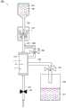
图5是表示本发明的实施方式2的血液净化装置的结构的回路图。如图5所示,本发明的实施方式2的血液净化装置200还包括分岔流路230。分岔流路230从清洗液流路130分岔并且与血液净化器110连接,以使清洗液流路130与第二部11连通。在分岔流路230上设有第三开闭阀290。清洗液流路130和分岔流路230的分岔部231设置在血液净化器110与血液泵170之间的位置。5 is a circuit diagram showing the configuration of a blood purification device according to
下面,对本发明实施方式2的血液净化装置200的动作进行说明。Next, the operation of
在血液净化装置200的透析开始前,使用清洗液141分别起动血液净化器110、血管通路120、清洗液流路130、排液流路150以及分岔流路230。Before the start of dialysis in
图6是表示本发明的实施方式2的血液净化装置的脱血行程的回路图。如图6所示,在本发明的实施方式2的血液净化装置200的脱血行程中,在第一开闭阀180打开、第二开闭阀190关闭、第三开闭阀290关闭的状态下,血液泵170向吸入方向输送液体。6 is a circuit diagram showing a blood removal process of the blood purification device according to
其结果是,血液如箭头1所示从血管进出流路120流入到血液净化器110的第一部10。通过血液净化器110的第一部10的血液流入到清洗液流路130。另外,在血液到达分岔部231之前,结束脱血行程。即,在脱血行程中,血液不会流入分岔流路230。As a result, blood flows into the
图7是表示本发明的实施方式2的血液净化装置的透析行程的回路图。如图7所示,在本发明的实施方式2的血液净化装置200的透析行程中,在第一开闭阀180关闭、第二开闭阀190打开、第三开闭阀290打开的状态下,血液泵170向排出方向输送液体。7 is a circuit diagram showing a dialysis process of the blood purification apparatus according to
其结果是,清洗液流路130内的血液流入到血液净化器110的第一部10。清洗液流路130内的清洗液141的一部分如箭头3a所示那样通过分岔流路230而流入到第二部11。As a result, the blood in the cleaning
流入到血液净化器110的第一部10的血液隔着半透膜111与第二部11的清洗液141接触,通过扩散原理,血液中的体内的废物移动到第二部11,从而被净化。从分岔流路230流入到第二部11中的清洗液141与通过半透膜111到达第二部11的血液中的体内的废物一起流入到排液流路150,并储存于排液储液部160。The blood flowing into the
图8是表示本发明的实施方式2的血液净化装置的除水行程的回路图。如图8所示,在本发明的实施方式2的血液净化装置200的除水行程中,在第一开闭阀180关闭、第二开闭阀190打开、第三开闭阀290关闭的状态下,血液泵170向排出方向输送液体。8 is a circuit diagram showing a water removal process of the blood purification device according to
其结果是,清洗液流路130内的血液流入到血液净化器110的第一部10。流入到血液净化器110的第一部10的血液通过来自血液泵170的加压而被半透膜111过滤。通过半透膜111并到达第二部11的排液161流入到排液流路150,并储存于排液储液部160。As a result, the blood in the cleaning
图9是表示本发明的实施方式2的血液净化装置的返血行程的回路图。如图9所示,在本发明的实施方式2的血液净化装置200的返血行程中,在第一开闭阀180打开、第二开闭阀190关闭、第三开闭阀290关闭的状态下,血液泵170向排出方向输送液体。其结果是,在血液净化器110中净化的血液如箭头5所示那样流入到血管进出流路120,并向患者返血。Fig. 9 is a circuit diagram showing a blood return process of the blood purification device according to
在本发明的实施方式2的血液净化装置200中,由于具有未形成血液回路的环的简易结构,并且交替地进行脱血行程和返血行程,因此,即使假设在发生穿刺针的脱离的情况下,也能够抑制失血量。具体而言,能够使失血量处于在脱血行程中流入到血液净化装置200内的血液的量以下。In the
另外,在返血工程中,在第一开闭阀180打开、第二开闭阀190关闭、第三开闭阀290打开的状态下,血液泵170也可以向排出方向输送液体。在这种情况下,位于第二部11的溶液通过来自血液泵170的加压而由半透膜111反向过滤。In addition, in the blood return process, the
(实施方式3)(Embodiment 3)
以下,参照附图对本发明的实施方式3的血液净化装置进行说明。由于本发明的实施方式3的血液净化装置主要在设置开关阀的位置的这一点上与实施方式2的血液净化装置200不同,因此,对于与血液净化装置200相同的结构不重复进行说明。Hereinafter, a blood purification device according to
图10是表示本发明的实施方式3的血液净化装置的结构的回路图。如图10所示,在本发明的实施方式3的血液净化装置300中,设有第四开闭阀390以代替第三开闭阀290。第四开闭阀390设置在清洗液流路130中的清洗液流路130和分岔流路230的分岔部231与血液净化器110之间的部分。另外,也可以设置第三开闭阀290以及第四开闭阀390的双方。10 is a circuit diagram showing the configuration of a blood purification device according to
下面,对本发明实施方式3的血液净化装置300的动作进行说明。Next, the operation of
在血液净化装置300的透析开始前,使用清洗液141分别起动血液净化器110、血管通路120、清洗液流路130、排液流路150以及分岔流路230。Before the start of dialysis in
图11是表示本发明的实施方式3的血液净化装置的脱血行程的回路图。如图11所示,在本发明的实施方式3的血液净化装置300的脱血行程中,在第一开闭阀180打开、第二开闭阀190关闭、第四开闭阀390打开的状态下,血液泵170向吸入方向输送液体。11 is a circuit diagram showing a blood removal process of the blood purification device according to
其结果是,如箭头1所示,血液从血管进出流路120流入到血液净化器110的第一部10。通过血液净化器110的第一部10的血液流入到清洗液流路130。另外,在血液到达分岔部231之前,结束脱血行程。即,在脱血行程中,血液不会流入到分岔流路230。As a result, blood flows into the
图12是表示本发明的实施方式3的血液净化装置的除水行程的回路图。如图12所示,在本发明的实施方式3的血液净化装置300的除水行程中,在第一开闭阀180关闭、第二开闭阀190打开、第四开闭阀390打开的状态下,血液泵170向排出方向输送液体。12 is a circuit diagram showing a water removal process of the blood purification device according to
其结果是,清洗液流路130内的血液流入到血液净化器110的第一部10。流入到血液净化器110的第一部10的血液通过来自血液泵170的加压而被半透膜111过滤。通过半透膜111到达第二部11的排液161流入到排液流路150,并储存于排液储液部160。As a result, the blood in the cleaning
图13是表示本发明的实施方式3的血液净化装置的返血行程的回路图。如图13所示,在本发明的实施方式3的血液净化装置300的返血行程中,在第一开闭阀180打开、第二开闭阀190关闭、第四开闭阀390关闭的状态下,血液泵170向排出方向输送液体。其结果是,位于第二部11的溶液通过来自血液泵170的加压而被半透膜111反向过滤,并且在血液净化器110中净化后的血液如箭头5所示流入到血管进出流路120,并向患者返血。Fig. 13 is a circuit diagram showing a blood return process of the blood purification device according to
在本发明的实施方式3的血液净化装置300中,由于具有未形成血液回路的环的简易结构,并且交替地进行脱血行程和返血行程,因此,即使假设在发生穿刺针的脱离的情况下,也能够抑制失血量。具体而言,能够使失血量处于在脱血行程中流入到血液净化装置300内的血液的量以下。In the
另外,本次公开的上述实施方式在所有点上均为例示,而并不作为限定解释的根据。因此,本发明的技术范围并非由仅上述实施方式来解释,而是基于权利要求书的记载来划定的。此外,包括与权利要求书相同意思以及范围内的所有变更。In addition, the above-mentioned embodiment disclosed this time is an illustration at all points, and should not be taken as a basis for a limited interpretation. Therefore, the technical scope of the present invention is not interpreted only by the above-mentioned embodiments, but defined based on the description of the claims. In addition, all changes within the meaning and range of a claim are included.
符号说明Symbol Description
10第一部、11第二部、100、200、300血液净化装置、110血液净化器、111半透膜、120血管进出流路、130清洗液流路、140清洗液储液部、141清洗液、150排液流路、160排液储液部、161排液、170血液泵、180第一开闭阀、190第二开闭阀、230分岔流路、231分岔部、290第三开闭阀、390第四开闭阀。10 first part, 11 second part, 100, 200, 300 blood purification device, 110 blood purifier, 111 semi-permeable membrane, 120 blood vessel inlet and outlet flow path, 130 cleaning liquid flow path, 140 cleaning liquid storage part, 141 cleaning liquid, 150 drain flow path, 160 drain liquid reservoir, 161 drain, 170 blood pump, 180 first on-off valve, 190 second on-off valve, 230 branch flow path, 231 branch part, 290 first Three opening and closing valves, 390 fourth opening and closing valves.
Claims (1)
Applications Claiming Priority (3)
| Application Number | Priority Date | Filing Date | Title |
|---|---|---|---|
| JP2017-122209 | 2017-06-22 | ||
| JP2017122209 | 2017-06-22 | ||
| PCT/JP2018/023907WO2018235963A1 (en) | 2017-06-22 | 2018-06-22 | Blood purification device |
Publications (2)
| Publication Number | Publication Date |
|---|---|
| CN110891628A CN110891628A (en) | 2020-03-17 |
| CN110891628Btrue CN110891628B (en) | 2023-02-21 |
Family
ID=64736024
Family Applications (1)
| Application Number | Title | Priority Date | Filing Date |
|---|---|---|---|
| CN201880041650.7AActiveCN110891628B (en) | 2017-06-22 | 2018-06-22 | blood purification device |
Country Status (5)
| Country | Link |
|---|---|
| US (1) | US11628241B2 (en) |
| EP (1) | EP3643341A4 (en) |
| JP (1) | JP7192768B2 (en) |
| CN (1) | CN110891628B (en) |
| WO (1) | WO2018235963A1 (en) |
Families Citing this family (1)
| Publication number | Priority date | Publication date | Assignee | Title |
|---|---|---|---|---|
| TWI860561B (en)* | 2022-10-20 | 2024-11-01 | 佳世達科技股份有限公司 | Hemodialysis device |
Citations (5)
| Publication number | Priority date | Publication date | Assignee | Title |
|---|---|---|---|---|
| CA1207243A (en)* | 1982-01-11 | 1986-07-08 | Elisabeth Bouveret | Alternative plasmapheresis and membrane apparatus for said process |
| US4648866A (en)* | 1983-07-07 | 1987-03-10 | Rhone-Poulenc S.A. | Process/apparatus for the withdrawal/return of body fluids |
| US4954128A (en)* | 1988-08-23 | 1990-09-04 | Baxter International Inc. | Therapeutics plasma exchange system |
| US5358482A (en)* | 1990-11-22 | 1994-10-25 | Roerig Farmaceutici Italiana S.R.L. | Single-needle extracorporeal plasmapheresis circuit |
| CN102971023A (en)* | 2010-07-05 | 2013-03-13 | 甘布罗伦迪亚股份公司 | An ambulatory ultrafiltration device, related methods and a computer program product |
Family Cites Families (9)
| Publication number | Priority date | Publication date | Assignee | Title |
|---|---|---|---|---|
| JPS6260562A (en) | 1985-09-10 | 1987-03-17 | 株式会社 ニツシヨ− | Method for detecting breakage of hollow yarn separator for plasma sampler |
| JP2503019B2 (en) | 1987-07-07 | 1996-06-05 | 株式会社クラレ | Plasma collection device |
| GB8724914D0 (en) | 1987-10-23 | 1987-11-25 | Research Corp Ltd | Blood purification apparatus |
| JP4325594B2 (en) | 2005-07-20 | 2009-09-02 | ニプロ株式会社 | Hemodialysis machine |
| KR101240773B1 (en) | 2008-05-26 | 2013-03-08 | 감브로 룬디아 아베 | A hemodialysis or hemo(dia)filtration apparatus and a method for controlling a hemodialysis or hemo(dia)filtration apparatus |
| DE102010020838A1 (en)* | 2010-05-18 | 2011-11-24 | Fresenius Medical Care Deutschland Gmbh | Valve assembly for use in extracorporeal blood circulation and method |
| CN102500005B (en) | 2011-09-30 | 2015-04-22 | 中南大学 | Blood transfusion system for autologous blood recovery, filtration and purification |
| DE102013006562A1 (en) | 2013-04-16 | 2014-10-16 | Fresenius Medical Care Deutschland Gmbh | Method for determining the pressure in an extracorporeal circuit |
| WO2015173713A1 (en)* | 2014-05-13 | 2015-11-19 | Monica Zanotti | Single needle hemo(dia)filtration apparatus |
- 2018
- 2018-06-22EPEP18819603.4Apatent/EP3643341A4/ennot_activeWithdrawn
- 2018-06-22JPJP2019525718Apatent/JP7192768B2/enactiveActive
- 2018-06-22USUS16/624,944patent/US11628241B2/enactiveActive
- 2018-06-22CNCN201880041650.7Apatent/CN110891628B/enactiveActive
- 2018-06-22WOPCT/JP2018/023907patent/WO2018235963A1/ennot_activeCeased
Patent Citations (5)
| Publication number | Priority date | Publication date | Assignee | Title |
|---|---|---|---|---|
| CA1207243A (en)* | 1982-01-11 | 1986-07-08 | Elisabeth Bouveret | Alternative plasmapheresis and membrane apparatus for said process |
| US4648866A (en)* | 1983-07-07 | 1987-03-10 | Rhone-Poulenc S.A. | Process/apparatus for the withdrawal/return of body fluids |
| US4954128A (en)* | 1988-08-23 | 1990-09-04 | Baxter International Inc. | Therapeutics plasma exchange system |
| US5358482A (en)* | 1990-11-22 | 1994-10-25 | Roerig Farmaceutici Italiana S.R.L. | Single-needle extracorporeal plasmapheresis circuit |
| CN102971023A (en)* | 2010-07-05 | 2013-03-13 | 甘布罗伦迪亚股份公司 | An ambulatory ultrafiltration device, related methods and a computer program product |
Also Published As
| Publication number | Publication date |
|---|---|
| CN110891628A (en) | 2020-03-17 |
| JPWO2018235963A1 (en) | 2020-04-23 |
| US11628241B2 (en) | 2023-04-18 |
| EP3643341A4 (en) | 2021-03-10 |
| WO2018235963A1 (en) | 2018-12-27 |
| EP3643341A1 (en) | 2020-04-29 |
| US20200139035A1 (en) | 2020-05-07 |
| JP7192768B2 (en) | 2022-12-20 |
Similar Documents
| Publication | Publication Date | Title |
|---|---|---|
| JP5205036B2 (en) | Blood purification equipment | |
| CN104379186A (en) | Blood purification device and priming method thereof | |
| US11931499B2 (en) | Pressure detector | |
| US11872334B2 (en) | Pressure detector | |
| JP5693890B2 (en) | Blood purification equipment | |
| EP3782673A1 (en) | Pressure detector | |
| US10576197B2 (en) | Blood purification device and priming method | |
| EP3744364A1 (en) | Pressure detector | |
| CN110891628B (en) | blood purification device | |
| US10314961B2 (en) | Dialysate-extracting apparatus | |
| JP5560954B2 (en) | Blood return operation method and blood purification apparatus in blood purification apparatus | |
| JP5558260B2 (en) | Blood processor priming system | |
| JP6296057B2 (en) | Automatic blood return method in case of emergency such as a power failure that occurred during blood purification | |
| JP5822152B2 (en) | Hemodialysis machine | |
| JP5760758B2 (en) | Hemodialysis machine | |
| JP6488048B2 (en) | Blood purification equipment | |
| JP2011194122A (en) | Blood purification apparatus | |
| JP7228005B2 (en) | blood purifier | |
| JP6700481B2 (en) | Blood purification device and priming method thereof | |
| JP6357496B2 (en) | Blood purification equipment | |
| JP2024147179A (en) | Blood Purification Device |
Legal Events
| Date | Code | Title | Description |
|---|---|---|---|
| PB01 | Publication | ||
| PB01 | Publication | ||
| SE01 | Entry into force of request for substantive examination | ||
| SE01 | Entry into force of request for substantive examination | ||
| GR01 | Patent grant | ||
| GR01 | Patent grant |