CN110888228A - Fluorescent microscopic illumination method adopting deep ultraviolet light source - Google Patents
Fluorescent microscopic illumination method adopting deep ultraviolet light sourceDownload PDFInfo
- Publication number
- CN110888228A CN110888228ACN201911169494.5ACN201911169494ACN110888228ACN 110888228 ACN110888228 ACN 110888228ACN 201911169494 ACN201911169494 ACN 201911169494ACN 110888228 ACN110888228 ACN 110888228A
- Authority
- CN
- China
- Prior art keywords
- light source
- deep ultraviolet
- fluorescence
- method adopting
- illumination method
- Prior art date
- Legal status (The legal status is an assumption and is not a legal conclusion. Google has not performed a legal analysis and makes no representation as to the accuracy of the status listed.)
- Pending
Links
Images


Classifications
- G—PHYSICS
- G02—OPTICS
- G02B—OPTICAL ELEMENTS, SYSTEMS OR APPARATUS
- G02B21/00—Microscopes
- G02B21/16—Microscopes adapted for ultraviolet illumination ; Fluorescence microscopes
Landscapes
- Physics & Mathematics (AREA)
- Chemical & Material Sciences (AREA)
- Analytical Chemistry (AREA)
- General Physics & Mathematics (AREA)
- Optics & Photonics (AREA)
- Investigating, Analyzing Materials By Fluorescence Or Luminescence (AREA)
- Microscoopes, Condenser (AREA)
Abstract
Description
Translated fromChinese技术领域technical field
本发明涉及显微镜技术领域,特别涉及一种荧光显微激发照明技术。The invention relates to the field of microscope technology, in particular to a fluorescence microscope excitation lighting technology.
背景技术Background technique
荧光显微镜具有对比度高、检出能力高、对细胞的刺激小、能进行多重染色等优点,可广泛应用于生物学、血液学、组织学、病理学、药物化学等研究以及临床试验之用。荧光显微镜主要由荧光激发源、聚光系统、滤色块(由激发滤色片、分光分色片和阻挡滤色片组成)和显微镜组成,一般是采用落射照明结构,具体原理是:荧光激发源通电后发出的光线经过聚光、激发滤色片(只能透过小于一定波长的光)和分光分色片(反射小于某波长的光,并能透射大于该波长的光)成像在物镜的后焦面上,与物镜形成一个柯拉照明系统,可以在样品上获得均匀的落射照明;样品受到落射照激发后产生荧光,其波长大于分光分色片能够透射的光的波长,此荧光直接透过分光分色片和阻挡滤色片(只能透过大于某一波长的光),到达目镜或者摄像装置以供观察。Fluorescence microscopy has the advantages of high contrast, high detection ability, little stimulation to cells, and multi-staining. It can be widely used in biology, hematology, histology, pathology, medicinal chemistry and other research and clinical trials. A fluorescence microscope is mainly composed of a fluorescence excitation source, a condensing system, a color filter block (consisting of an excitation filter, a dichroic filter and a blocking filter) and a microscope. Generally, an epi-illumination structure is used. The specific principle is: fluorescence excitation The light emitted after the source is energized passes through the condensing, excitation filter (only transmits light less than a certain wavelength) and dichroic filter (reflects light less than a certain wavelength, and can transmit light greater than this wavelength) and is imaged on the objective lens. On the back focal plane, it forms a Kola illumination system with the objective lens, which can obtain uniform epi-illumination on the sample; after the sample is excited by epi-illumination, it produces fluorescence, the wavelength of which is greater than the wavelength of the light that can be transmitted by the spectroscopic dichroic plate, and this fluorescence Directly through the dichroic filter and blocking filter (only light with a wavelength greater than a certain wavelength can be transmitted) to the eyepiece or camera device for observation.
因为物镜同时充当聚光和成像作用,结构简单,受到广泛的应用。但对于特殊波长如深紫外(350nm以下),由于常规荧光物镜、聚光系统只能透过紫外以上的波长,该方法就不适用,除非全部重新设计,但代价昂贵。Because the objective lens acts as light-gathering and imaging functions at the same time, it has a simple structure and is widely used. However, for special wavelengths such as deep ultraviolet (below 350nm), since conventional fluorescent objective lenses and concentrating systems can only transmit wavelengths above ultraviolet, this method is not applicable unless all are redesigned, but it is expensive.
现有专利CN107003242 A公开一种使用荧光剂进行染色之后在紫外激发的情况下使用荧光显微镜控制组织中的成像深度的系统和方法,采用斜照明方式,即照明聚光和成像部分独立,解决了物镜不能透深紫外的问题,但对于高倍物镜,由于工作距离短(如1mm左右),斜照明的利用率就非常低,甚至不能用。The existing patent CN107003242 A discloses a system and method for using a fluorescent microscope to control the imaging depth in tissue under the condition of ultraviolet excitation after dyeing with a fluorescent agent. The problem that the objective lens cannot penetrate deep ultraviolet, but for the high magnification objective lens, due to the short working distance (such as about 1mm), the utilization rate of oblique illumination is very low, or even unusable.
现有专利CN 205091263U、CN105092550A公开了一种荧光显微成像方法和装置,包括光源装置、样品放置台、物镜、发射滤光模组和图像获取装置,光源装置包括多个单色荧光激发光源和与多个单色荧光激发光源电连接的控制系统,多个单色荧光激发光源环绕物镜和图像获取装置所构成的成像光路中轴设置,且每个单色荧光激发光源所发出的单色荧光激发光与成像光路中轴相交于样品放置台的预设位置,控制系统根据实验要求在多个单色荧光激发光源中点亮至少一个相同颜色的单色荧光激发光源为目标光源;样品放置台设置于多个单色荧光激发光源所发出的单色荧光激发光交汇位置。但该对比文件是用于透射荧光,需要滤色块,其成本也较高。Existing patents CN 205091263U and CN105092550A disclose a fluorescence microscope imaging method and device, including a light source device, a sample placement table, an objective lens, an emission filter module and an image acquisition device, the light source device includes a plurality of monochromatic fluorescence excitation light sources and A control system electrically connected with a plurality of monochromatic fluorescence excitation light sources, the plurality of monochromatic fluorescence excitation light sources are arranged around the central axis of the imaging optical path formed by the objective lens and the image acquisition device, and the monochromatic fluorescence emitted by each monochromatic fluorescence excitation light source The central axis of the excitation light and the imaging optical path intersect at the preset position of the sample placement stage, and the control system lights at least one monochromatic fluorescence excitation light source of the same color among the multiple monochromatic fluorescence excitation light sources as the target light source according to the experimental requirements; the sample placement stage It is arranged at the intersection of the monochromatic fluorescence excitation light emitted by a plurality of monochromatic fluorescence excitation light sources. However, the comparison file is used for transmitted fluorescence, which requires a color filter block, and its cost is also high.
发明内容SUMMARY OF THE INVENTION
本发明在于提供一种采用深紫外光源的荧光显微照明方法。本发明的技术方案是,将深紫外激发光源及其聚光系统安装在物镜周围,激发光源发出的光经聚光系统后形成暗场照明照射在标本面上,激发标本发出荧光,经物镜收集后在成像到目镜上。The present invention is to provide a fluorescence microscope illumination method using a deep ultraviolet light source. The technical scheme of the present invention is that the deep ultraviolet excitation light source and its light-condensing system are installed around the objective lens, the light emitted by the excitation light source passes through the light-condensing system to form dark field illumination and is irradiated on the specimen surface, and the specimen is excited to emit fluorescence, which is collected by the objective lens. and then imaged onto the eyepiece.
所述的荧光激发光源为紫外固态光源,其波长小于400nm。如LED,固态激光,优选的为LED,LED固定在环形电路板上。The fluorescent excitation light source is an ultraviolet solid-state light source, and its wavelength is less than 400 nm. Such as LED, solid-state laser, preferably LED, and the LED is fixed on the ring circuit board.
所述的紫外固态光源为LED。The ultraviolet solid-state light source is LED.
所述的荧光激发光源的数量可以一颗或者多颗。The number of the fluorescent excitation light sources may be one or more.
所述的在波长上可以是单种波长,或多种波长的组合。The wavelength can be a single wavelength, or a combination of multiple wavelengths.
所述的聚光系统为透镜、离轴抛物面,离轴曲面的任意一种或其组合。The light collecting system is any one of a lens, an off-axis paraboloid, an off-axis curved surface, or a combination thereof.
所述的聚光系统用以将激发光源发出的光形成暗场照明会聚在标本面上,与所述的物镜的焦面重合。The light condensing system is used for condensing the light emitted by the excitation light source to form dark field illumination on the specimen surface, which is coincident with the focal plane of the objective lens.
所述的透镜必须可以透深紫外,如石英玻璃。The lens must be transparent to deep ultraviolet, such as quartz glass.
现有技术专利中的荧光显微镜要使用滤色块,通过滤色块改变波长,每一发射滤光区域得通过波段为样品板内颗粒受一颜色的单色荧光激发光源的激发而发出的荧光的波段。而本发明不需要使用滤色块,通过荧光激发光源就能改变波长,从而达到激发样品荧光的目的。本发明可使用短工作距离的物镜,避免了光能损耗,光学效率更高;同时本发明不需要滤色块,结构简单且成本更低。The fluorescence microscope in the prior art patent uses a color filter block, and the wavelength is changed through the color filter block. the band. However, the present invention does not need to use a color filter block, and the wavelength can be changed through the fluorescence excitation light source, thereby achieving the purpose of exciting the fluorescence of the sample. The invention can use an objective lens with a short working distance, avoids the loss of light energy, and has higher optical efficiency; meanwhile, the invention does not need a color filter block, and has a simple structure and lower cost.
附图说明Description of drawings
此处所说明的附图用来提供对本发明的进一步理解,构成本发明的一部分,本发明的示意性实施例及其说明用于解释本发明,并不构成对本发明的不当限定。在附图中:The accompanying drawings described herein are used to provide further understanding of the present invention and constitute a part of the present invention. The exemplary embodiments of the present invention and their descriptions are used to explain the present invention and do not constitute an improper limitation of the present invention. In the attached image:
图1所示本发明专利单独的曲面反射镜示意图。Figure 1 shows a schematic diagram of a single curved mirror of the patent of the present invention.
图2所示本发明专利透深紫外示意图。Figure 2 shows a schematic diagram of the patent of the present invention through deep ultraviolet.
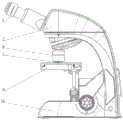
图3所示本发明专利显微镜透深紫外示意图。Figure 3 shows a schematic diagram of the invention's patented microscope through deep ultraviolet.
图4所示本发明专利透深紫外结构示意图。FIG. 4 shows a schematic diagram of the structure of the patent of the present invention transparent to deep ultraviolet.
具体实施方式Detailed ways
为进一步说明各实施例,本发明提供有附图。这些附图为本发明揭露内容的一部分,其主要用以说明实施例,并可配合说明书的相关描述来解释实施例的运作原理。配合参考这些内容,本领域普通技术人员应能理解其他可能的实施方式以及本发明的优点。图中的组件并未按比例绘制,而类似的组件符号通常用来表示类似的组件。To further illustrate the various embodiments, the present invention is provided with the accompanying drawings. These drawings are a part of the disclosure of the present invention, which are mainly used to illustrate the embodiments, and can be used in conjunction with the relevant description of the specification to explain the operation principles of the embodiments. With reference to these contents, one of ordinary skill in the art will understand other possible embodiments and advantages of the present invention. Components in the figures are not drawn to scale, and similar component symbols are often used to represent similar components.
如图1、2、3、4所示,本发明提供一种采用深紫外光源的荧光显微照明方法,包括1、标本,2、离轴抛物面,3、光源,4、物镜,5、目镜,6、透镜阵列,7、头部,8、暗场物镜,9、载物台,10、机架,11、物镜内胆,12、线扣,13、外壳组成,其中所述的深紫外激发光源3为固态光源,如LED,固态激光,优选的为LED,光源3固定在环形电路板上。光源3的数量可以单颗,也可以多颗。在波长上可以是单种波长,也可以多种波长组合。As shown in Figures 1, 2, 3, and 4, the present invention provides a fluorescence microscope illumination method using a deep ultraviolet light source, comprising: 1, a specimen, 2, an off-axis paraboloid, 3, a light source, 4, an objective lens, and 5, an eyepiece , 6, lens array, 7, head, 8, dark field objective lens, 9, stage, 10, frame, 11, objective lens liner, 12, wire buckle, 13, shell composition, wherein the deep ultraviolet The
将深紫外激发光源3,及其聚光系统安装在物镜周围,激发光源3发出的光经聚光系统后形成暗场照明照射在标本1面上,激发标本1发出荧光,经物镜4收集后在成像到目镜5上。其中所述的聚光系统为透镜阵列6、离轴抛物面2,离轴曲面任意一种或其组合。The deep ultraviolet
所述的聚光系统,用以将激发光源3发出的光形成暗场照明会聚在标本1面上,与该物镜4的焦面重合。所述的聚光系统可以由环形透镜、透镜阵列6与曲面反射镜组合,如图1所示,可以单独的曲面反射镜如离轴抛物面反射镜,透镜必须可以透深紫外,如石英玻璃。The light-condensing system is used for condensing the light emitted by the
尽管结合优选实施方案具体展示和介绍了本发明,但所属领域的技术人员应该明白,在不脱离所附权利要求书所限定的本发明的精神和范围内,在形式上和细节上对本发明做出各种变化,均为本发明的保护范围。Although the present invention has been particularly shown and described in connection with preferred embodiments, it will be understood by those skilled in the art that changes in form and detail can be made in the present invention without departing from the spirit and scope of the invention as defined by the appended claims. Various changes are within the protection scope of the present invention.
Claims (9)
Priority Applications (1)
| Application Number | Priority Date | Filing Date | Title |
|---|---|---|---|
| CN201911169494.5ACN110888228A (en) | 2019-11-26 | 2019-11-26 | Fluorescent microscopic illumination method adopting deep ultraviolet light source |
Applications Claiming Priority (1)
| Application Number | Priority Date | Filing Date | Title |
|---|---|---|---|
| CN201911169494.5ACN110888228A (en) | 2019-11-26 | 2019-11-26 | Fluorescent microscopic illumination method adopting deep ultraviolet light source |
Publications (1)
| Publication Number | Publication Date |
|---|---|
| CN110888228Atrue CN110888228A (en) | 2020-03-17 |
Family
ID=69748801
Family Applications (1)
| Application Number | Title | Priority Date | Filing Date |
|---|---|---|---|
| CN201911169494.5APendingCN110888228A (en) | 2019-11-26 | 2019-11-26 | Fluorescent microscopic illumination method adopting deep ultraviolet light source |
Country Status (1)
| Country | Link |
|---|---|
| CN (1) | CN110888228A (en) |
Cited By (1)
| Publication number | Priority date | Publication date | Assignee | Title |
|---|---|---|---|---|
| CN113534430A (en)* | 2021-06-08 | 2021-10-22 | 浙江工商职业技术学院 | Design method and device of dark field condenser for metallographic microscope |
Citations (9)
| Publication number | Priority date | Publication date | Assignee | Title |
|---|---|---|---|---|
| JP3142994U (en)* | 2008-04-22 | 2008-07-03 | 株式会社渋谷光学 | Dark field illumination device |
| CN101414056A (en)* | 2008-12-05 | 2009-04-22 | 南京东利来光电实业有限责任公司 | Dark field illumination objective lens apparatus |
| CN201355404Y (en)* | 2009-02-24 | 2009-12-02 | 南京东利来光电实业有限责任公司 | Dark field lighting object lens device |
| JP2012013879A (en)* | 2010-06-30 | 2012-01-19 | Nikon Corp | Objective lens for epidark illumination, and microscope |
| CN202533371U (en)* | 2012-03-27 | 2012-11-14 | 武汉鹰飞拓光电子有限公司 | Deep ultraviolet (DUV) laser Raman spectrometer |
| CN102955238A (en)* | 2011-08-22 | 2013-03-06 | 安鹏科技股份有限公司 | Handheld Fluorescence Microscope |
| CN103364386A (en)* | 2012-03-27 | 2013-10-23 | 武汉鹰飞拓光电子有限公司 | Deep ultraviolet laser Raman spectrometer |
| CN108931511A (en)* | 2018-06-04 | 2018-12-04 | 常州市武进区半导体照明应用技术研究院 | The fluorescence detection device and method of ultraviolet LED |
| CN211123468U (en)* | 2019-11-26 | 2020-07-28 | 麦克奥迪实业集团有限公司 | Fluorescent micro-lighting device adopting deep ultraviolet light source |
- 2019
- 2019-11-26CNCN201911169494.5Apatent/CN110888228A/enactivePending
Patent Citations (9)
| Publication number | Priority date | Publication date | Assignee | Title |
|---|---|---|---|---|
| JP3142994U (en)* | 2008-04-22 | 2008-07-03 | 株式会社渋谷光学 | Dark field illumination device |
| CN101414056A (en)* | 2008-12-05 | 2009-04-22 | 南京东利来光电实业有限责任公司 | Dark field illumination objective lens apparatus |
| CN201355404Y (en)* | 2009-02-24 | 2009-12-02 | 南京东利来光电实业有限责任公司 | Dark field lighting object lens device |
| JP2012013879A (en)* | 2010-06-30 | 2012-01-19 | Nikon Corp | Objective lens for epidark illumination, and microscope |
| CN102955238A (en)* | 2011-08-22 | 2013-03-06 | 安鹏科技股份有限公司 | Handheld Fluorescence Microscope |
| CN202533371U (en)* | 2012-03-27 | 2012-11-14 | 武汉鹰飞拓光电子有限公司 | Deep ultraviolet (DUV) laser Raman spectrometer |
| CN103364386A (en)* | 2012-03-27 | 2013-10-23 | 武汉鹰飞拓光电子有限公司 | Deep ultraviolet laser Raman spectrometer |
| CN108931511A (en)* | 2018-06-04 | 2018-12-04 | 常州市武进区半导体照明应用技术研究院 | The fluorescence detection device and method of ultraviolet LED |
| CN211123468U (en)* | 2019-11-26 | 2020-07-28 | 麦克奥迪实业集团有限公司 | Fluorescent micro-lighting device adopting deep ultraviolet light source |
Cited By (2)
| Publication number | Priority date | Publication date | Assignee | Title |
|---|---|---|---|---|
| CN113534430A (en)* | 2021-06-08 | 2021-10-22 | 浙江工商职业技术学院 | Design method and device of dark field condenser for metallographic microscope |
| CN113534430B (en)* | 2021-06-08 | 2023-10-10 | 浙江工商职业技术学院 | Design method and device of a dark-field condenser for metallographic microscopes |
Similar Documents
| Publication | Publication Date | Title |
|---|---|---|
| EP1780574B1 (en) | Microscope systeme with an illuminatig unit | |
| US6924930B2 (en) | Microscope illumination device | |
| CN105092550A (en) | Fluorescent microscopic imaging method and device | |
| CN103698309B (en) | STED super-resolution microscope based on tunable laser | |
| CN104865688B (en) | The microscope of external fluorescent moieties | |
| US8014065B2 (en) | Microscope apparatus with fluorescence cube for total-internal-reflection fluorescence microscopy | |
| TWI476395B (en) | Fluorescence imaging module | |
| WO2001061324A1 (en) | Fluorescence microscopy methods and devices using light emission diodes | |
| US10634890B1 (en) | Miniaturized microscope for phase contrast and multicolor fluorescence imaging | |
| CN107942530B (en) | Integrated optical waveguide super-resolution microscopy imaging system | |
| CN108780216B (en) | Imaging systems and methods utilizing scattering to reduce derived fluorescence and improve uniformity | |
| WO2011096835A1 (en) | Device for analyzing luminescent bio-microchips | |
| CN115508994A (en) | Microscopic imaging system | |
| CN110888228A (en) | Fluorescent microscopic illumination method adopting deep ultraviolet light source | |
| CN211123468U (en) | Fluorescent micro-lighting device adopting deep ultraviolet light source | |
| JP2007271529A (en) | Microscopic fluorescence observation device | |
| CN106979460A (en) | A kind of fluorescence light source and fluorescence microimaging systems | |
| WO2024227348A1 (en) | Optical system integrating optogenetic stimulation and optical signal detection, and imaging apparatus | |
| CN218181202U (en) | A Microscopic Imaging System | |
| WO2004070366A1 (en) | Fluorescence imaging system and biomanupilator system using same | |
| CN207018828U (en) | A kind of fluorescence light source and fluorescence microimaging systems | |
| JP2004530111A (en) | Continuous sample observation device by fluorescence | |
| WO2017068627A1 (en) | Microscope | |
| JPH03266809A (en) | Vertical fluorescent microscope for ultraviolet range | |
| CN104570311A (en) | Fluorescence microscope based on multi-spectral LED light source |
Legal Events
| Date | Code | Title | Description |
|---|---|---|---|
| PB01 | Publication | ||
| PB01 | Publication | ||
| SE01 | Entry into force of request for substantive examination | ||
| SE01 | Entry into force of request for substantive examination | ||
| WD01 | Invention patent application deemed withdrawn after publication | ||
| WD01 | Invention patent application deemed withdrawn after publication | Application publication date:20200317 |